

Page 1
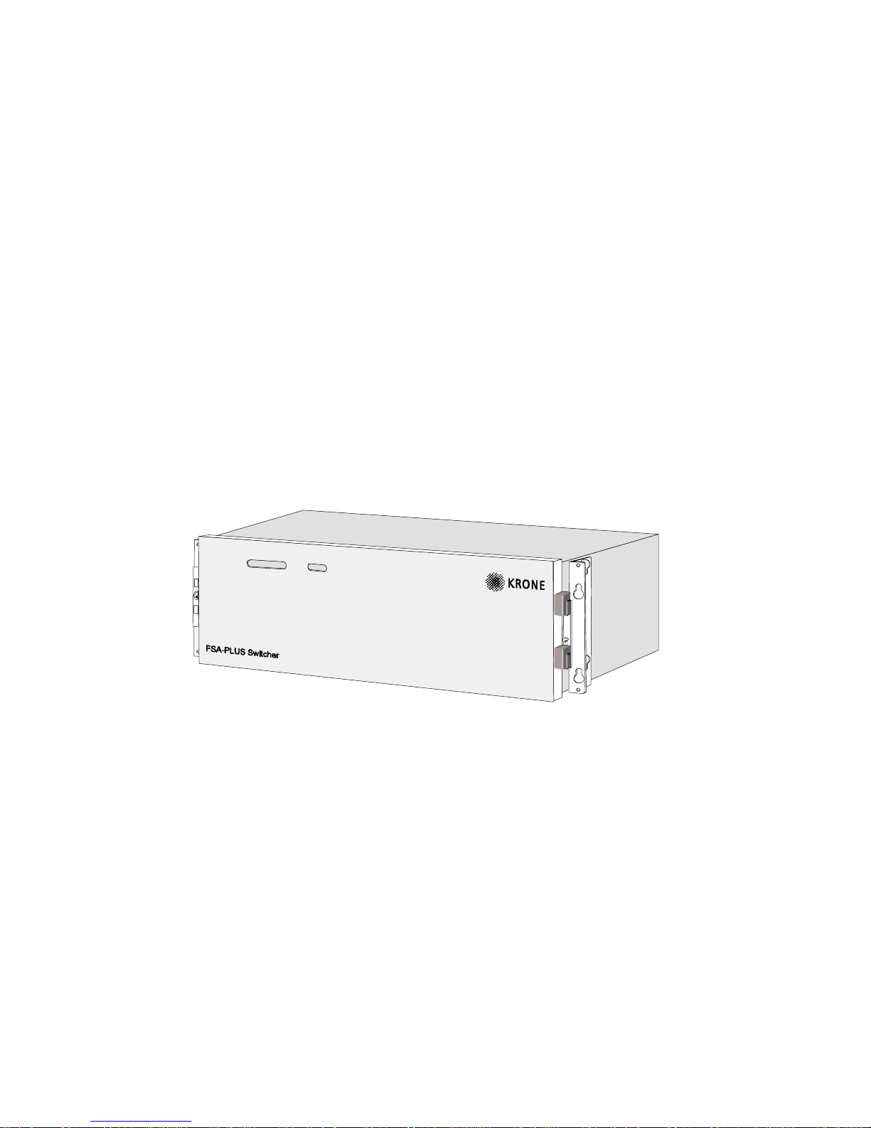
TECHNICAL MANUAL
FSA-PLUS
SWITCHER
(MODEM VERSION)
Page 2

FSA-PLUS Switcher (Modem Version)
Technical Manual
6341 3 103-12 - 17.05.2011
Page 2
Table of Contents
1 Introduction ................................................................................................. 4
2 Selectable Services .................................................................................... 5
3 Tranfer Switch ............................................................................................ 6
4 Applications of the FSA-PLUS Switcher ..................................................... 7
4.1 Application in Double Mode ........................................................................ 7
4.2 Application in Single Mode ....................................................................... 10
5 Monitoring and Alarms .............................................................................. 11
5.1 Monitoring and Alarms in Double Mode .................................................... 11
5.1.1 Monitoring and Signalling of FSA-PLUS Switcher (central or external
FSA-PLUS Switcher) ................................................................................ 11
5.1.2 Additional Monitoring and Signalling of the Central FSA-PLUS Switcher . 11
5.2 Monitoring and Alarms in Single Mode ..................................................... 12
6 Interfaces ................................................................................................ .. 13
6.1 Power Supply ........................................................................................... 13
6.2 Modem Interface ....................................................................................... 14
6.3 Interface for Line Measurements (Double Mode only) or for an External
Switch (Double Mode or Single Mode) ..................................................... 15
6.4 Interface for an Alarm Contact .................................................................. 16
7 Considerations for Use ............................................................................. 17
7.1 Operation and Connecting Plans for the Control Card (FCU)................... 17
7.1.1 Path Switching (Double Mode) ................................................................. 17
7.1.2 Single Mode .............................................................................................. 19
7.2 Overview of the Position of Operational Controls and Connecting
Elements on the Control Card (FCU) ........................................................ 20
7.3 Pin Connection Table for the Control Card (FCU) .................................... 21
7.4 Settings and Configurations ..................................................................... 22
7.4.1 Addressing the Moving Card (MOC) ......................................................... 22
7.4.2 Configuration of the Control Card (FCU) .................................................. 23
7.5 Signalling .................................................................................................. 24
7.5.1 Signalling during the Switch-On Process .................................................. 24
7.5.2 Signalling in Double Mode ........................................................................ 25
7.5.3 Signalling in Single Mode ......................................................................... 26
7.6 Refresh ..................................................................................................... 27
Page 3

FSA-PLUS Switcher (Modem Version)
Technical Manual
6341 3 103-12 - 17.05.2011
Page 3
8 General Characteristics and References .................................................. 27
8.1 Mechanics and Construction .................................................................... 27
8.2 Climate and Environment ......................................................................... 27
8.3 Electromagnetic Compatibility .................................................................. 28
8.4 Safety Regulations ................................................................................... 28
8.5 Safety Instructions .................................................................................... 28
9 Ratings ..................................................................................................... 29
10 Trouble-shooting ....................................................................................... 30
Page 4

FSA-PLUS Switcher (Modem Version)
Technical Manual
6341 3 103-12 - 17.05.2011
Page 4
1 Introduction
The following technical manual describes a safety transfer (switchover) switch as
part of the FSA-PLUS family (FSA Switcher — Flexible, Safe, Automatic). The
transfer switch can also reverse all standard communication services with a
bandwidth of up to 60 MHz. The restrictions of the connected services are to be
found within the framework of category three and/or the former category four.
Page 5

FSA-PLUS Switcher (Modem Version)
Technical Manual
6341 3 103-12 - 17.05.2011
Page 5
2 Selectable Services
The FSA-PLUS Switchers are designed in such a way that the following services
can be connected in accordance with the corresponding specifications of ETSI
and BellCore:
Plain Old Telephony Service (POTS)
ISDN Basic Rate,
ISDN Primary Rate,
64 kbit/s and 2 Mbit/s and 1.5 Mbit/s permanent leased line
High speed Digital Subscriber Line (HDSL)
Asymmetric Digital Subscriber Line (ADSL)
Data services, which satisfy the following boundary conditions, can also be connected:
Max. connectable voltage 1 220 VAC / 200 VDC2
Max. connectable current 1 1 A 2
Max. connectable power 1 60 WAC / 30 WDC 2
Max. bandwidth < 60 MHz
LSA-PLUS lines are fitted without primary protection elements for the termination
of the service cable (coming and going).
1
For reasons of electrical safety in case of accidental contact, only homopolar earthed TNV sig-
nals (telecommunication network voltage) or SELV signals (safety extra low voltage) are permitted in accordance with EN 60950 !
2
Passing over these limiting values leads to the destruction of the device!
Page 6
FSA-PLUS Switcher (Modem Version)
Technical Manual
6341 3 103-12 - 17.05.2011
Page 6
3 Transfer Switch
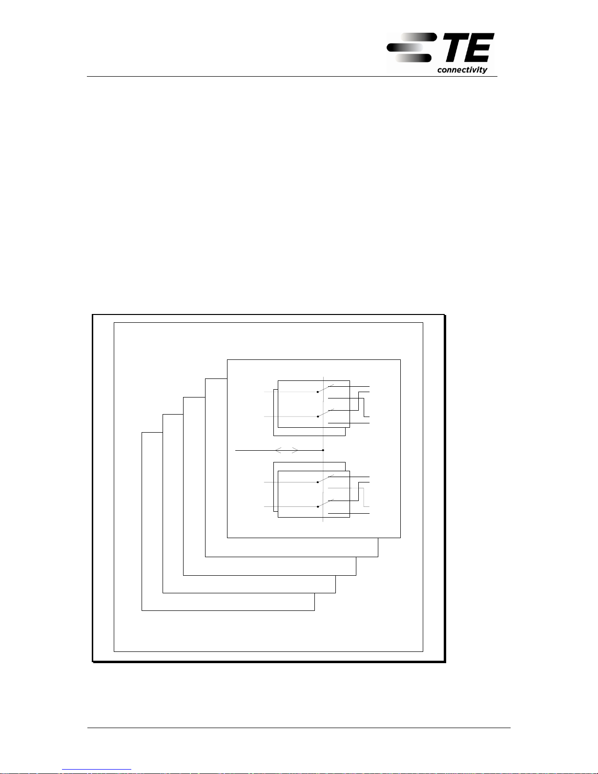
The FSA-PLUS Switcher is designed as a relay-based reversing switch with the
switch function of a change-over contact. With each switching action, all relays will
be switchover together. The max. switching capacity amounts to 100 x 200 copper
pairs. The reversing switch consists of up to five identical groups of components
(Moving Card MOC). Each one of these groups of components switches 20 copper pairs over to 40 copper pairs. The FSA-PLUS Switcher can be equipped with
a random number of MOCs, up to the maximum number. Retroactive fitting or
stripping down by adding or removing MOCs is also possible.
Failures of the power supply do not alter the interconnection state (due to the
bistable relay used!).
MOC 2
(assemb ly set)
MOC 3
(assemb ly set)
MOC 4
(assemb ly set)
MOC 5
(assembly set)
FSA-PLUS Switcher
Side1
Side2
Tip
Ring
Ring
Tip
Tip
Ring
IN / OUT
1 twisted
pair
Side1
Side2
Tip
Ring
Ring
Tip
Tip
Ring
IN / OUT
Switch 20
Switch 19
Switch 1
Switch 2
Controls
MOC 1
(basic unit)
1 twisted
pair
Picture 1: Reversing switch of the FSA-PLUS Switcher
Page 7

FSA-PLUS Switcher (Modem Version)
Technical Manual
6341 3 103-12 - 17.05.2011
Page 7
4 Applications of the FSA-PLUS Switcher
The FSA -PLUS Switcher can be used both for the switching of one device or system over to another device or system (single mode) and for the switching of a
transmission path over to another transmission path (double mode).
4.1 Application in Double Mode
The FSA-PLUS Switcher can be used in double mode for critical connections
which do not permit interruptions in the event of disturbances on the line level
(e.g. connections to banks, air traffic control, hospitals, etc.).
In double mode, two FSA-PLUS Switchers form a system which, by means of
variable reverse switching criteria, can switch from one transmission path over to
another transmission path. In each switch-over, both FSA-PLUS Switchers are always jointly switched over.
The interaction of the two FSA-PLUS Switchers is carried out by means of a permanent modem connection which enables a distance range of up to 10km. The
modem interface required for this is integrated in the FSA-PLUS Switcher.
The complete signalling of both FSA-PLUS Switcher for switch status and possible
alarms is carried out on the central FSA-PLUS Switcher. The external
FSA-PLUS Switcher limits the signalling to the display of its own switch status as
well as its own alarms.
Page 8
FSA-PLUS Switcher (Modem Version)
Technical Manual
6341 3 103-12 - 17.05.2011
Page 8
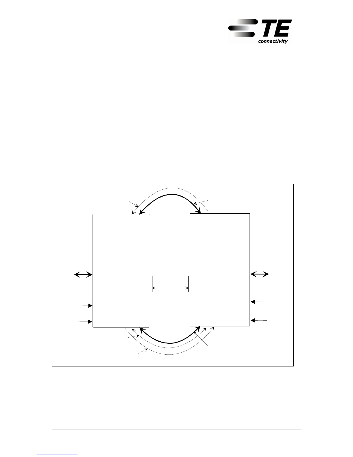
The reverse switching criterion for the FSA-PLUS Switcher can be selected from
among the following possibilities:
Automatic Reversing
In the case of automatic reversing, the line quality of a copper pair is applied as
reverse switching criterion and this is monitored by means of the external
FSA-PLUS Switcher. At the same time, the line is tested for disturbance and a
minimum insulating resistance of wire to wire and wire to earth. After falling
short of specific limiting values, it is automatically switched from the main path
(SIDE1) over to the reserve path (SIDE2) and a special alarm is set to on.
The switching from the reserve path over to the main path is only possible after
a selectively targeted manual reset.
Central
FSA-PLUS Switcher
External
FSA-PLUS Switcher
Modem leased line
connection
100 copper pairs for signal
and data transmission
(Main path, SIDE1)
Distance
max. 10 km
Monitoring of the line
quality
(Main path)
Monitoring of the
line quality
(Reserve path)
100 copper pairs
for signal and
data transmission
100 copper pairs
for signal and
data transmission
100 copper pairs for signal
and data transmission
(Reseve path, SIDE2)
Power supply
Power supply
Alarm contact
Alarm contact
Picture 2: Application of the FSA-PLUS Switcher in double mode;
Automatic path switching
Page 9
FSA-PLUS Switcher (Modem Version)
Technical Manual
6341 3 103-12 - 17.05.2011
Page 9
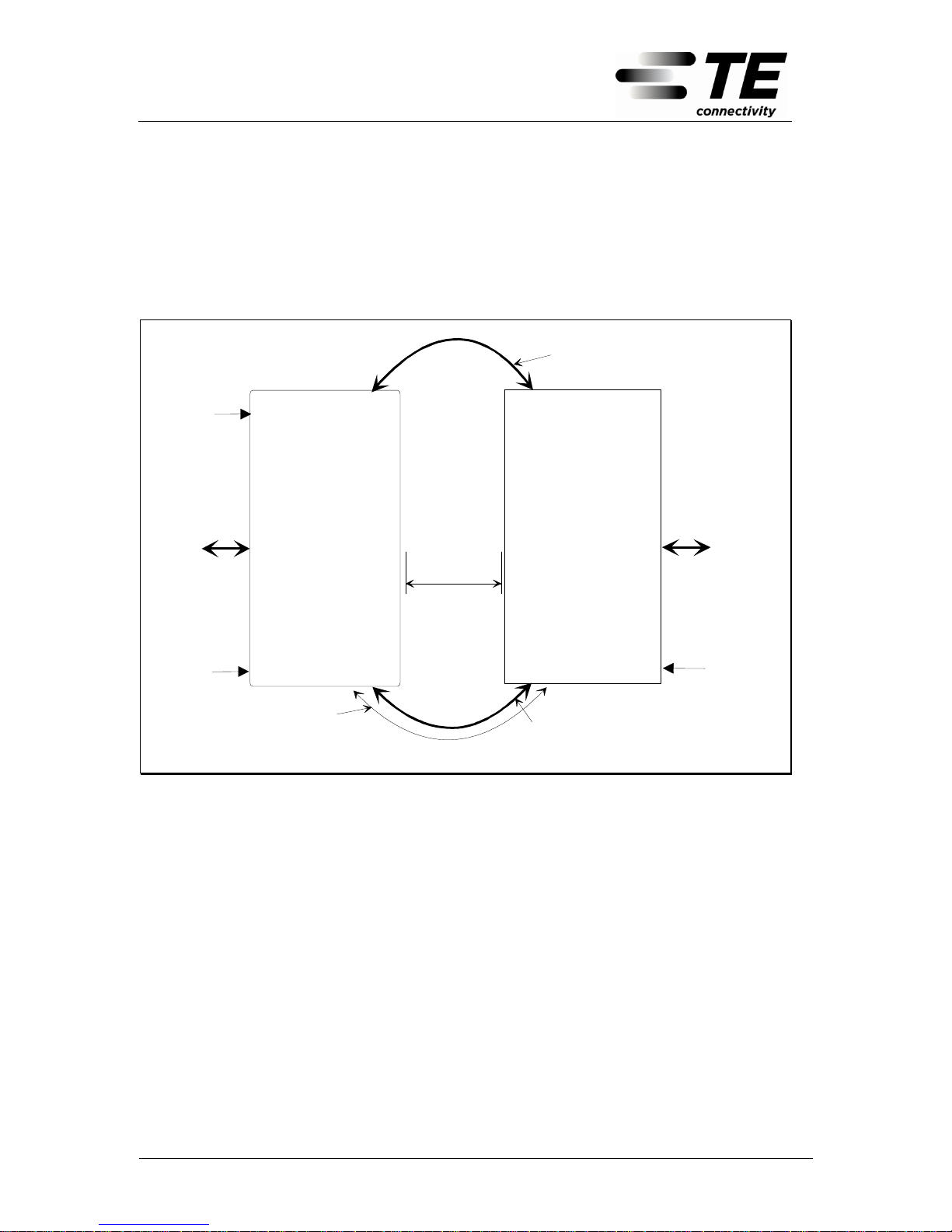
Manual Reverse Switching
Manual reverse switching can only be carried out via the central FSA-PLUS
Switcher. The criterion for reverse switching is determined (according to the
configuration) either by a local switch on the Switcher or by a remote switch.
The distance of the remote switch can run to several hundred metres.
Central
FSA-PLUS Switcher
External
FSA-PLUS Switcher
Modem leased line
connection
110V - 230V AC (AC-Version)
40,5V - 72V DC (DC-Version)
110V - 230V AC (AC-Version)
40,5V - 72V DC (DC-Version)
100 copper pairs for signal
and data tranmission
(Main path)
Distance
max. 10 km
Interface for an
external switch
100 copper pairs
for signal and
data tranmission
100 copper pairs
for signal and
data tranmission
100 copper pairs for signal
and data tranmission
(Reserve path)
Picture 3: Application of the FSA-PLUS Switcher in double mode;
Manual path switching
Page 10
FSA-PLUS Switcher (Modem Version)
Technical Manual
6341 3 103-12 - 17.05.2011
Page 10
4.2 Application in Single Mode
In single mode, an FSA-PLUS Switcher forms a reverse switching system which
switchover, by means of variable reverse switching criteria, a device A from a device B over to a device C (e.g. subscriber‘s extension stations, etc.).
The criterion for reverse switching for the FSA-PLUS Switcher can be selected
from among the following possibilities:
Manual external reverse switching
Manual external reverse switching is carried out by means of an external
switch, which can be situated at a distance of up to several hundred metres
away.
Manual local reverse switching
Manual local reverse switching is carried out by means of a switch positioned in
the device.
FSA-PLUS Switcher
110V - 230V AC (AC-Version)
40,5V - 72V DC (DC-Version)
Interface for an
external switch
Galvanic separate
contact for the signalling
of an urgent alarm
100 copper pairs for data
and signal transmission
(Main path, SIDE1)
Device A
Device B
Device C
100 copper pairs for data
and signal transmission
(Reserve path, SIDE2)
100 copper pairs for data
and signal transmission
Picture 4: Application of the FSA-PLUS Switcher in the single mode.
Page 11

FSA-PLUS Switcher (Modem Version)
Technical Manual
6341 3 103-12 - 17.05.2011
Page 11
5 Monitoring and Alarms
The FSA-PLUS Switcher provides extensive options for monitoring as well as the
alarms resulting from this, independent of the configuration.
5.1 Monitoring and Alarms in Double Mode
In double mode, the monitoring and signalling of alarms for the central and external FSA-PLUS Switcher is different, since only the central FSA-PLUS Switcher
receives all the information from the complete system (both FSA-PLUS Switchers). The signalling in the case of the external FSA-PLUS Switcher is limited to its
own status and its own alarms.
5.1.1 Monitoring and Signalling of FSA-PLUS Switcher (Central or External
FSA-PLUS Switcher)
Signalling of switch status
Signalling of operating conditions (auto / manual operation)
Monitoring of all moving cards by means of cyclic write / read operations and
alarm in the event of failure
Recognition of the number of moving cards
Comparison of the number of moving cards (double mode only)
Alarm in the event of failure of an internal voltage
Alarm in the event of failure of the primary supply voltage (DC version only)
Monitoring of the modem connection
Alarm in the event of failure of the modem connection
Monitoring and signalling of the interface for the measurement of the line. In the
case of operation with automatic reverse switching, there is an alarm in addition
to the signalling.
5.1.2 Additional Monitoring and Signalling of the Central FSA-PLUS
Switcher
The central FSA-PLUS Switcher monitors the whole system, i.e. it monitors both
FSA-PLUS Switchers according to the criteria cited in section 5.1.1.
In addition, there is a specifically targeted alarm with details of the alarm as well
as the alarm source which is effected by the central FSA-PLUS Switcher.
In the event of failure of the primary supply voltage (DC version only) or an operating voltage of the external FSA-PLUS Switcher, this failure leads to a specifically
targeted urgent alarm in the FSA-PLUS Switcher.
Page 12

FSA-PLUS Switcher (Modem Version)
Technical Manual
6341 3 103-12 - 17.05.2011
Page 12
5.2 Monitoring and Alarms in Single Mode
Monitoring and signalling of the FSA-PLUS Switcher
Signalling of the switch status
Monitoring of all moving cards by means of cyclical write / read operations
and alarm in the event of failure
Recognition of the number of moving cards
Alarm in the event of failure of an internal voltage
Alarm in the event of failure of the primary distribution voltage (DC version
only)
Page 13

FSA-PLUS Switcher (Modem Version)
Technical Manual
6341 3 103-12 - 17.05.2011
Page 13
6 Interfaces
6.1 Power Supply
The FSA-PLUS Switcher is available in an AC version (Alternating Current) and a
DC version (Direct Current).
The power supply of the AC version is designed in such a way that 115 V / 60 Hz
as well as 230 V / 50 Hz can be used for the primary supply. The adjustment of
the power supply to the primary supply voltage occurs automatically.
The power supply of the DC version satisfies the requirements of the European
standard EN ETS 300 132-2 with a possible range of input voltage of
40.5V - 72V DC. The adjustment of the power supply to the primary supply voltage
occurs automatically.
Permitted range of the input voltage
(AC version):
85 - 264 VAC (50 Hz - 60 Hz)
Permitted range of the input voltage
(DC version):
40.5 - 72 VDC in accordance with
ETS 300 132-2
In the case of reverse poling of the interface for the power supply on the FCU
(control card) there is no possibility of normal operation. Reverse poling is nondestructive.
Page 14

FSA-PLUS Switcher (Modem Version)
Technical Manual
6341 3 103-12 - 17.05.2011
Page 14
6.2 Modem Interface
The accommodation of two FSA-PLUS Switchers is carried out by means of a
permanent modem connection. This connection is a necessary condition for the
operation of the device. A breakdown in the modem connection causes a specifically targeted alarm to be set off. In this case a reverse switching of the FSAPLUS Switcher is not possible.
Transmission rate 1200 baud/s, half duplex FSK Modem in accordance with
ITU-T V.23
Maximum distance of up to 10 km in the case of standard lines of telecommu-
nication with the following characteristics (typical values)
Line diameter
in mm
Direct current loop
resistance in
/ km
Line capacity in
nF / km
Maximum possible
distance in km
0.4
270
50 8 0.5
190
50 9 0.6
120
50
10
Monitoring of the communication: start bit; stop bit; check total, time out moni-
toring
Satisfies the requirements of ETSI TBR 15 (Jan. 97) and the Dutch regula-
tion T14-01
Control of the communication is carried out by means of the polling principle. The
external FSA-PLUS Switcher is the master with regard to communication.
With every polling cycle, the external FSA-PLUS Switcher informs the central
FSA-PLUS Switcher of the switch status and the alarm status.
The required connection and the monitoring of the switching operation is carried
out by the central FSA-PLUS Switcher.
Page 15

FSA-PLUS Switcher (Modem Version)
Technical Manual
6341 3 103-12 - 17.05.2011
Page 15
6.3 Interface for Line Measurements (Double Mode only) or for an External
Switch (Double Mode or Single Mode)
Interfaces for line measurements (double mode only)
The interfaces for line measurements are monitored by an in-circuit copper pair for
a specified minimum insulation resistance (a-wire to b-wire and a-wire or b-wire to
earth) and for a possible opening of the circuit.
Two interfaces are required in order to perform this measurement which is carried
out by an FSA-PLUS Switcher continuously. One interface forms the source with
the appropriate evaluation and the other interface forms a necessary terminal
(see picture2, Chapter 4.1).
The guaranteed values are as follows:
Threshold value for the insulation,
measured a-wire to b-wire and a-wire or
b-wire to earth
Guaranteed values over the whole
specified temperature range
Minimum possible insulation value,
which still does not trigger any alarm
(Lower values must have triggered off
an alarm)
R
Insulation_min
> 1.5 M
Notice: The max. permitted loop resistance
of the cable is 3 k
Maximum insulation value at which an
alarm is triggered
(Higher insulation values must reset an
alarm and/or not trigger any alarm off)
R
Insulation_max
< 5 M
Values for the loop resistance of
the cable
Guaranteed values over the whole
specified temperature range
Highest switching threshold:
Higher values must trigger an alarm
R
Loop
< 100 k
Lowest switching threshold:
Lower values must reset an alarm
and/or must not trigger any alarm off
R
series
> 3 k
Page 16
FSA-PLUS Switcher (Modem Version)
Technical Manual
6341 3 103-12 - 17.05.2011
Page 16
Interface for an external switch (double or single mode)
Values for the loop resistance of the
cable
Guaranteed values over the whole
specified temperature range
Highest switching threshold:
Higher values must lead to the switching from SIDE1 over to SIDE2
(External switch is open)
R
Loop_SIDE2
300k
Lowest switching threshold:
Lower values must lead to the switching
from SIDE2 over to SIDE1
(External switch is closed)
R
Loop_SIDE1
3 k
The function of the external switch is assigned in the following manner:
External switch closed
Switch on SIDE1
External switch open
Switch on SIDE2
6.4 Interface for an Alarm Contact
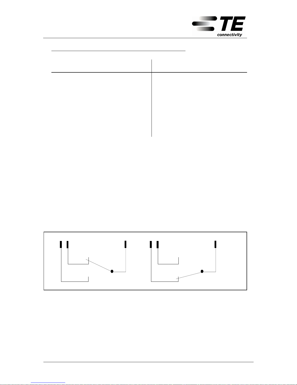
The interface for the alarm consists of galvanic separated relay contacts. The contacts have the function of a three-way switch.
The assignation of the contacts is as follows:
Pin 5
Pin 4Pin 6
Pin 5
Pin 4Pin 6
Alarm Normal Operation
Picture 5: Assignment of the alarm contacts
Page 17
FSA-PLUS Switcher (Modem Version)
Technical Manual
6341 3 103-12 - 17.05.2011
Page 17
7 Considerations for Use
7.1 Operation and Connecting Plans for the Control Card (FCU)
7.1.1 Path Switching (Double Mode)
With path switching, all the cables are switched together from one bunch of trunks
over to another bunch of trunks. Two FSA-PLUS Switchers are required to perform this reverse switching and these must be installed on each end of the bunch
of trunks. The accommodation of the FSA-PLUS Switcher is carried out by means
of a permanent modem connection.
In the case of automatic reverse switching, a copper pair is applied as the switch
criterion, on which the insulation and the loop resistance are monitored. In the
event of falling short of the defined thresholds (see Page 15) it is automatically
switched from the main path (SIDE1) over to the reserve path (SIDE2).
In double mode, after a connection of the central FSA-PLUS Switcher, a comparison is carried out of the number of recognised moving cards of the two FSA-PLUS
Switcher. In the event of unequal numbers of recognised moving cards, this gives
rise to an alarm and signalling (flashing of LED 3,4,8 or 9). A switch operation is
not possible then.
An automatic switching over to SIDE2 is a once-through operation, independent of
the monitored line data. This switch behaviour will prevent any multiple switching
over from taking place. In addition, it is therefore possible to carry out the switch
back from SIDE2 to SIDE1 to a self-defined time.
In the event that the FSA-PLUS Switcher has automatically switched to SIDE2
and a failure of the distribution voltage or the operating voltage +15V subsequently occurs, this switch status is filed in an internal memory and after restoration of the voltage is used once again as switch status. An undesired switch back
on SIDE1 is therefore prevented.
For a direct switch back onto SIDE1 involves two possibilities. The first possibility
is an application of key S3 (see Page 20) of the external FSA-PLUS Switcher.
When the key is pressed, the LED 4 lights up in acknowledgement. This LED, in
the case of the external FSA-PLUS Switcher, has no other function.
LOCAL
SWITCH
SIDE 1
SIDE 2
EXTERNAL SWITCHER
CENTRAL SWITCHER
FCU
Top view
16
XS1
1
S2
XS4
S3
1
4
S1
Reset
Buttom
ON
OFF
1
4
DIP-switch for the
configuration mode
1
2
4
3
5
6
7
8
9
10
11
12
Picture 6: Front view of the function control unit (FCU)
The second possibility is a reversed configuration of the central FSA-PLUS
Switcher in manual mode with the subsequent reversed configuration once again
in automatic mode. In this case, the internal memory is erased. The system there-
Page 18
FSA-PLUS Switcher (Modem Version)
Technical Manual
6341 3 103-12 - 17.05.2011
Page 18
fore sets itself automatically at normal status SIDE1 (assuming that the lines are
perfect).
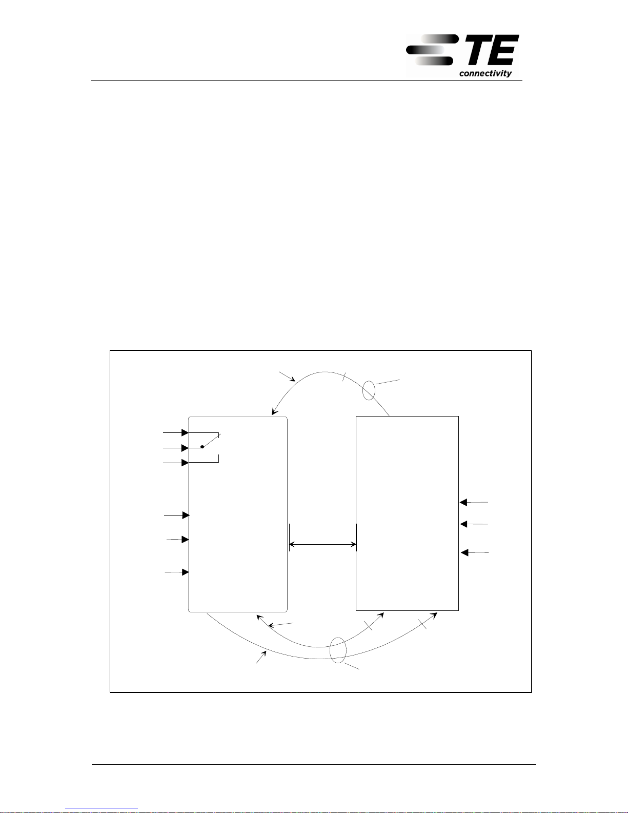
The installation of the lines required for automatic reverse switching should be carried out in accordance with the following installation plan.
The main path (path in the event of perfect operation) is installed on SIDE1.
The reserve path (reserve path) is installed on SIDE2.
The modem connection must be installed with the bunch of trunks from SIDE2
in order to guarantee the communication even in the event of damage to the
cable of the main path.
The monitoring of the cable in the main path must be carried out by means of
the external FSA-PLUS Switcher. In the event of a failure of the lines in the reserve path (SIDE2), it is then possible to determine whether the failure is
caused by the modem connection or the lines.
Control card from
the central
FSA-PLUS Switcher
Distance
max. 10 km
Monitoring of the line
quality
(Main path, SIDE1)
Control card from
external
FSA-PLUS Switcher
2
2
Pin2
Pin3
Supply
Pin2
Pin3
Pin15
2
Pin11
Pin12
Pin8
Pin9
Pin16
(+)
(-)
Earth
Pin14
This line must be placed in
the main path (SIDE1)
Pin14
(-)
(+)
Pin15
Pin16
Pin11
Pin12
Pin8
Pin9
Pin5
Pin4
Contact for an urgent
combined alarm
Pin6
This line must be placed in
the reserve path (SIDE2)
Monitoring of the line
quality
(Reserve path, SIDE2)
Supply
Earth
Permanent
modem
connection
Picture 7: Automatic path switching
Page 19
FSA-PLUS Switcher (Modem Version)
Technical Manual
6341 3 103-12 - 17.05.2011
Page 19
Distance
max. 10 km
Control card from
the external
FSA-PLUS Switcher
Pin2
Pin3
Pin2
Pin3
Pin15
2
Pin8
Pin9
Pin16
(+)
(-)
Pin14
This line must be placed in the
reverse path (SIDE2)
Pin14
Earth
(-)
(+)
Pin15
Pin16
Supply
2
Connect here the external
switch (if used)
Pin5
Pin4
Contact foran
central
alarm
Pin6
Permanent
modem
connection
Control card from
the central
FSA-PLUS Switcher
Supply
Earth
Picture 8: Manual path switching
7.1.2 Single Mode
Control card of the
FSA-PLUS Switcher
Supply
Pin15
Pin8
Pin9
Pin16
(+)
(-)
Earth
Pin14
2
Connect here the
external switch
(if used)
Pin5
Pin4
Contact for
the central
alarm
Pin6
Picture 9: Single mode
Page 20
FSA-PLUS Switcher (Modem Version)
Technical Manual
6341 3 103-12 - 17.05.2011
Page 20
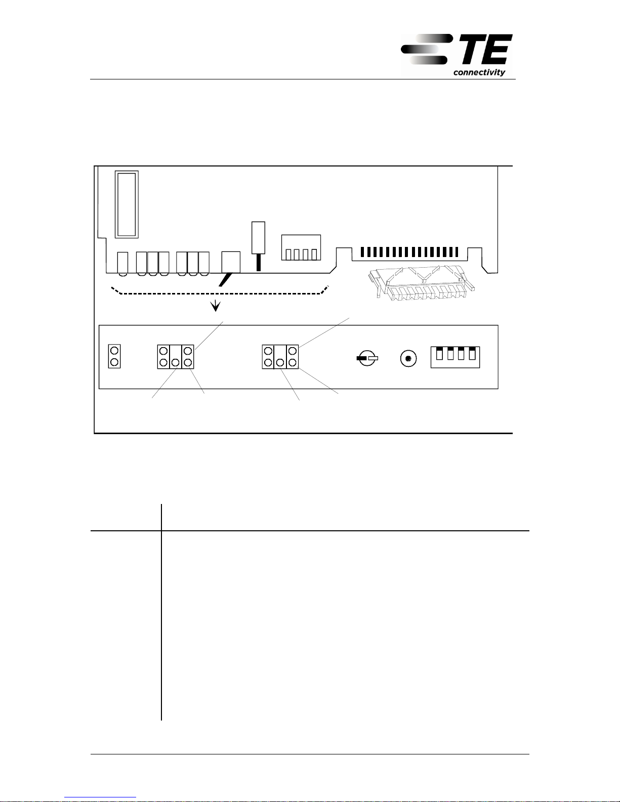
7.2 Overview of the Position of Operational Controls and Connecting Ele-
ments on the Control Card (FCU)
SIDE 1
SIDE 2
Local
switch
SIDE 1
SIDE 2
EXTERNAL
SWITCHER
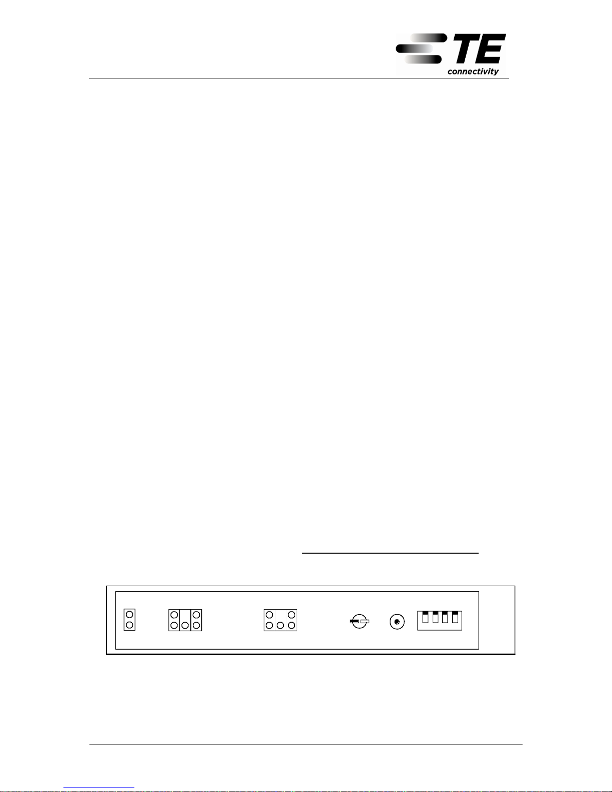
SIDE 1
SIDE 2
CENTRAL
SWITCHER
URGENT
ALARM
AUTO
MODE
Cable error
FCU
top view
16
XS1
1
S2
XS4
S3
1
4
S1
Reset
button
ON
OFF
1
4
DIP-switch
Configuration
Supply failure
Cable error
Modem signal received (flashes)
No modem signal received (lights up permanently)
Modem signal received (flashes)
Supply failure
1
16
No modem signal received (lights up permanently)
Picture 10: Control card (FCU)
Name
Description of Function
S1
Dip switch for setting the configuration
S2
Local switch
S3
Push button for the specifically targeted switch back on SIDE1 (only
external switch in automatic path switching mode)
XS1
Connector plug of the control card for the external interfaces
(This is connected with a 16-pin PCB connecting block)
XS4
Interface between the control card and the moving cards
Page 21
FSA-PLUS Switcher (Modem Version)
Technical Manual
6341 3 103-12 - 17.05.2011
Page 21
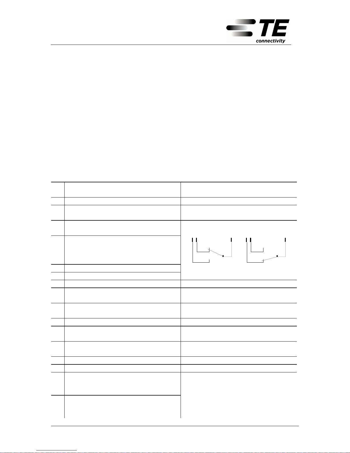
7.3 Pin Connection Table for the Control Card (FCU)
The wiring of the control card is carried out by means of a 16-pin PCB connecting
block ”XS1” with the IDC method of termination.
The connectable line diameter on the PCB connecting block of the control card
(FCU)
is 0.4mm – 0.6mm
The position of the socket with the corresponding subscriber‘s numbers can be
seen in the Picture on Page 17.
Installation is carried out using a special LSA-PLUS tool (included in delivery).
Connecting plug XS1 of the FCU
is connected with the 16-pin PCB connecting block
Pin
Nº
Name
Comments
1.
Not connected
2.
Modem connection wire-a to the other
FSA-PLUS Switcher
No demand on the polarity
3.
Modem connection wire-b to the other
FSA-PLUS Switcher
No demand on the polarity
4.
Alarm contact
Pin 5
Pin 4Pin 6
Pin 5
Pin 4Pin 6
5.
Central alarm contact
Alarm
Normal operation
6.
Alarm contact
7.
Not connected
8.
Insulation measurement wire-a or con-
nection of an external switch, contact-a
No demand on the polarity
9.
Insulation measurement wire-b or con-
nection of an external switch, contact-b
No demand on the polarity
10.
Not connected
11.
Terminal for insulation measurement
wire-a
No demand on the polarity
12.
Terminal for insulation measurement
wire-b
No demand on the polarity
13.
Not connected
14.
Earth
Connect to earth
15.
+ supply
AC version: Connection of the
power
supply (+15V)
16.
- supply
DC version: Connection of the DC
primary supply
(48V/60V)
Page 22

FSA-PLUS Switcher (Modem Version)
Technical Manual
6341 3 103-12 - 17.05.2011
Page 22
7.4 Settings and Configurations
7.4.1 Addressing the Moving card (MOC)
Each moving card (MOC) of the FSA-PLUS Switcher must be addressed oncethrough before the start of operation. With this coordination, each MOC will allocate a unique fixed address which enables a specifically targeted triggering and
signalling. Addressing is carried out on the10-pin connecting block and a plug-in
bridge. The configuration of the MOC will differ in MOC1 .... MOC5. MOC1 is the
lowest and MOC5 the highest placed moving card in the Switcher. The names
MOC1..MOC5 are imprinted on the respective pins of the connecting blocks and
are easily visible.
An address of the MOC must never be assigned more than once. This leads to a
malfunction in the FSA-PLUS Switcher. A defined switching of the FSA-PLUS
Switcher is then no longer guaranteed.
The addressed moving cards are tested and indicated in the switch-on process
(see Chapter 7.5.1)
In double mode, following the connection of the central FSA-PLUS Switcher, a
comparison is made of the number of recognised moving cards of both FSA-PLUS
Switcher. In the event of unequal numbers of recognised moving cards, an alarm
is activated.
Page 23

FSA-PLUS Switcher (Modem Version)
Technical Manual
6341 3 103-12 - 17.05.2011
Page 23
7.4.2 Configuration of the Control Card (FCU)
Configuration Mode
Switch criterion is the line
quality with automatic reverse switching
ON
OFF
1
4
Double Mode
Central FSA-PLUS
Switcher
Manual reverse switching
Local switch is the re-
verse switching criterion
ON
OFF
1
4
Manual reverse switching
External switch is the re-
verse switching criterion
ON
OFF
1
4
External FSA-PLUS
Switcher
The external FSA-PLUS
Switcher is controlled only by
the central FSA-PLUS
Switcher
ON
OFF
1
4
Single Mode
Local switch is the reverse switching criterion
ON
OFF
1
4
External switch is the reverse switching criterion
ON
OFF
1
4
Any modification of the configuration may only be carried out when the FSA-PLUS
Switcher is turned off.
AC version: Switch off the plug-in power unit
DC version: Turn off distribution voltage or pull out 16-pin PCB connecting
block on the control card (FCU).
Page 24
FSA-PLUS Switcher (Modem Version)
Technical Manual
6341 3 103-12 - 17.05.2011
Page 24
7.5 Signalling
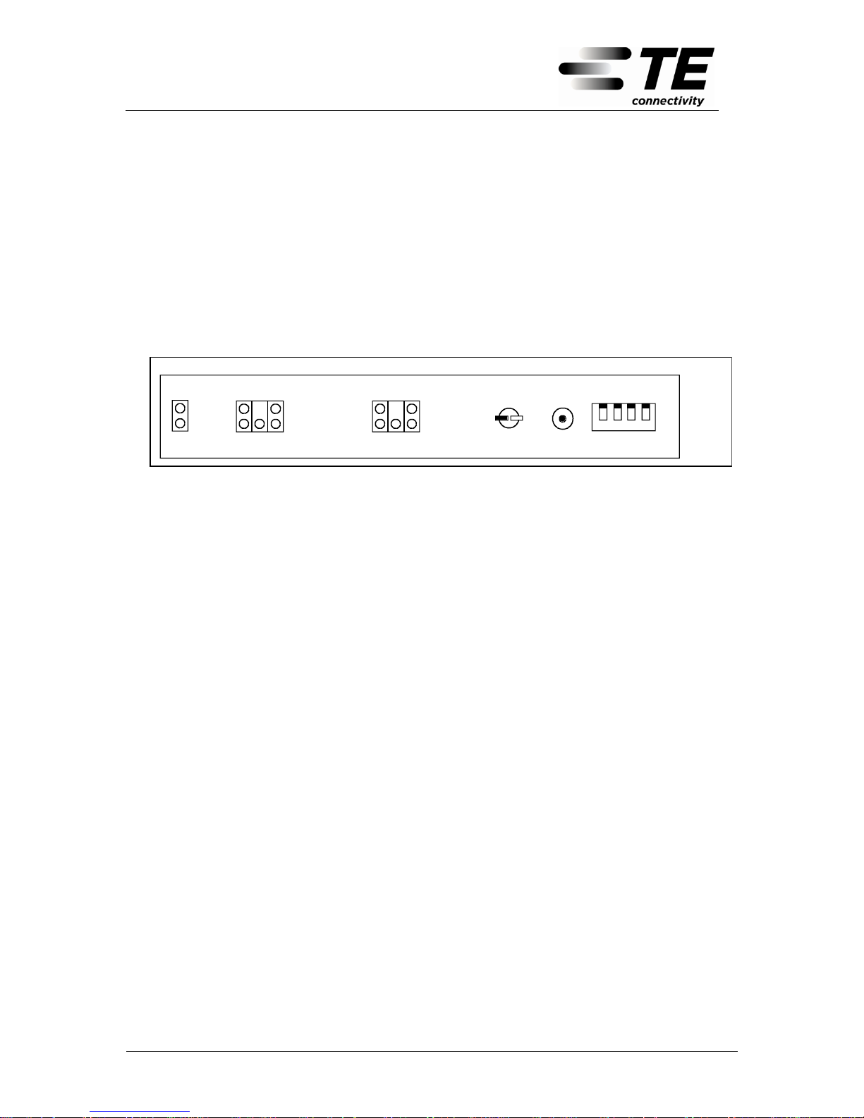
7.5.1 Signalling during the Switch-On Process
After the FSA-PLUS Switcher has been switched on, a test routine is carried out
with the following signalling, independent of the configuration which has been set:
During the first 3 seconds, all the LEDs light up for a LED test (LED Test)
During the following 3 seconds, all perfect recognised moving cards (MOC) are
displayed. Each MOC is assigned to a LED as follows:
MOC 1
ON
OFF
1
4
MOC 2
MOC 3
MOC 4
MOC 5
Picture 11: Front view of the function control unit (FCU)
The status of ”no MOC recognised” leads to a fatal error. This will be signalled by
the flashing of all the LEDs.
This is followed by the stable signalling of operational status
The test routine can be repeated at random without this leading to any variation in
the switching status of the FSA-PLUS Switcher.
There the FSA-PLUS Switcher is turned off and then turned on again after a waiting time of approx. 5 seconds. The signalling occurs once again as described
above.
In double mode, after the central FSA-PLUS Switcher has been switched on, a
comparison is made of the number of recognised moving cards (MOC) of both
FSA-PLUS Switcher. In the event of an unequal number of recognised moving
cards, an alarm is activated.
Page 25
FSA-PLUS Switcher (Modem Version)
Technical Manual
6341 3 103-12 - 17.05.2011
Page 25
7.5.2 Signalling in Double Mode
LOCAL
SWITC H
SIDE 1
SIDE 2
EXTERNAL SW ITCHER
CENTRAL SWITCHER
FCU
Top view
16
XS1
1
S2
XS4
S3
1
4
S1
Reset
Buttom
ON
OFF
1
4
DIP-sw itch for the
configu ration mode
1
2
4
3
5
6
7
8
9
10
11
12
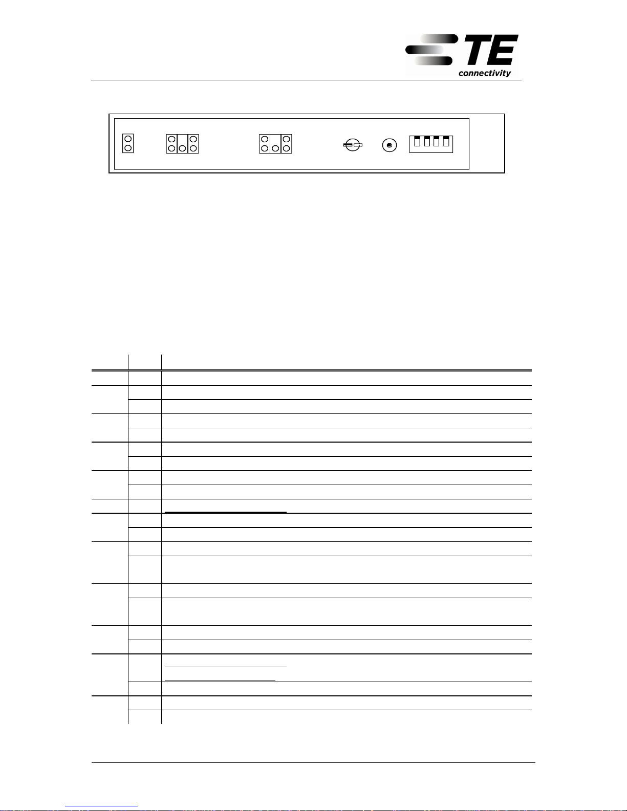
Picture 10: Front view of the function control unit (FCU)
The signalling is allocated as follows:
LED 1 Central Switcher: Central alarm of the system (both Switchers)
External Switcher: Central alarm only of the external Switcher
LED 2 Configuration
This LED always lights up in the case of the external Switcher,
since this is only controlled by the central Switcher
LED 3-7 Signalling of the status of the central FSA-PLUS Switcher
This signalling is only possible in the case of the central FSA-
PLUS Switcher
LED 8-12 Signalling of the status of the external FSA-PLUS Switcher
LED Nº
Description of the Signalling
1 X Signals a collective urgent alarm
2 X Automatic reverse switching activated.
O Manual reverse switching (external switch or local switch)
3 X Central Switcher is switched to SIDE1
B Central Switcher is switched to SIDE1; Switcher cannot switch because there is an alarm
4 X Central Switcher is switched to SIDE2
B Central Switcher is switched to SIDE2; Switcher cannot switch because there is an alarm
5 X Central Switcher does not receive a modem signal
B Central Switcher receives a modem signal.
6 X Automatic reverse switching: Poor line values on SIDE2.
7 X Operating voltage of 15V is too low
B Primary supply voltage of < 40.5V is too low (DC version only)
8 X External Switcher is switched to SIDE1
B External Switcher is switched to SIDE1; Switcher cannot switch because there is an
alarm 9 X
External Switcher is switched to SIDE2
B External Switcher is switched to SIDE2; Switcher cannot switch because there is an
alarm
10
X
External Switcher does not receive a modem signal
B External Switcher receives a modem signal.
11
X
Automatic reverse switching: Poor line values on SIDE1.
Manual reverse switching: Interface is not connected (Does not cause an alarm)
B Cable error SIDE1 has been detected. Now the cable has no errors again
12
X
Operating voltage of 15V is too low (<14,0V)
B Primary supply voltage of < 40.5V is too low (DC version only)
X: LED lights up permanently O: LED does not light up B: LED flashes
Page 26
FSA-PLUS Switcher (Modem Version)
Technical Manual
6341 3 103-12 - 17.05.2011
Page 26
7.5.3 Signalling in Single Mode
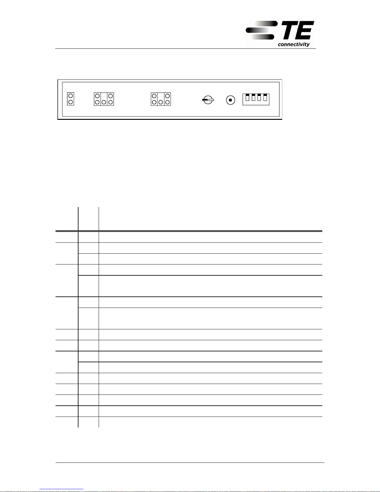
Picture 11: Front view of the function control unit (FCU)
The signalling is allocated as follows:
LED 1 Central alarm of the FSA-PLUS Switcher
LED 2 Configuration
LED 3-7 Signalling of the status of the FSA-PLUS Switcher
LED 8-12 Have no function in single mode (except at the switch-on moment)
LED
Nº
Description of the Signalling
1
X
Signals a collective urgent alarm
2
X
Reverse switching is carried out by the external switch.
O Reverse switching is carried out by the local switch (local switch, see above)
3
X
FSA-PLUS Switcher is switched to SIDE1
B FSA-PLUS Switcher is switched to SIDE1; Switcher cannot switch because there is
an alarm
4
X
FSA-PLUS Switcher is switched SIDE2
B FSA-PLUS Switcher is switched to SIDE2; Switcher cannot switch because there is
an alarm
5
No function
6
X
No function
7
X
Operating voltage of 15V is too low
B Primary supply voltage of < 40.5V is too low (DC version only)
8
No function
9
No function
10
No function
11
No function
12
No function
X: LED lights up permanently O: LED does not light up B: LED flashes
LOCAL
SWITCH
SIDE 1
SIDE 2
EXTERNAL SWITCHER
CENTRAL SWITCHER
FCU
Top view
16
XS1
1
S2
XS4
S3
1
4
S1
Reset
Buttom
ON
OFF
1
4
DIP-switch for the
configuration mode
1
2
4
3
5
6
7
8
9
10
11
12
Page 27

FSA-PLUS Switcher (Modem Version)
Technical Manual
6341 3 103-12 - 17.05.2011
Page 27
7.6 Refresh
The FSA-PLUS Switcher carries out a refresh process every 20 hours. This process is a test routine to test the availability of all the moving cards. In this test routine, all moving cards are switched once again to the side on which they just find
themselves. This process has no influence on the switched connections. The
monitoring of failures is carried out up to the driver of the relay. A direct monitoring
of the delay is not supported.
The recognition of a defective moving card activates an alarm. A reverse switching
is not possible then.
8 General Characteristics and References
8.1 Mechanics and Construction
The FSA-PLUS Switcher is designed in the form of a 19” shelf in accordance with
IEC 297. An adaptation to a rack in accordance with IEC 917 (metric construction)
is possible3.
The shelf is designed as a self-contained fabricated steel sheet structure. The
elimination of heat is carried out by natural convection.
The shelf has an overall height of 4 units. The depth amounts to 225 mm.
The connection field accommodates the LSA-PLUS lines and the feeding of the
power supply.
8.2 Climate and Environment
According to the area of application, the climatic conditions of environmental
class 3.1 (indoor) are satisfied in accordance with ETS 300 019 Part 1-3.
3
The mounting angles of the sub-racks are asymmetrical so that mounting in 19" and in 500 mm framing
is possible.
Page 28

FSA-PLUS Switcher (Modem Version)
Technical Manual
6341 3 103-12 - 17.05.2011
Page 28
8.3 Electromagnetic Compatibility
The electromagnetic characteristics of the FSA-PLUS Switcher comply with the
European norms EN 50081-1 and EN50082-2.
8.4 Safety Regulations
The FSA-PLUS Switcher certainly complies with the European norm EN 60950/A4
as well as ITU K.20
8.5 Safety Instructions
Area of application:
Structured cabling systems and telecommunication networks
Instructions for electrical safety:
In applications for SELV circuits (data networks), unlimited use
In applications for TNV1-3 circuits, the FSA-PLUS Switcher can only be in-
stalled by factory technicians.
The installation must only be carried out by qualified staff!
Page 29

FSA-PLUS Switcher (Modem Version)
Technical Manual
6341 3 103-12 - 17.05.2011
Page 29
9 Ratings
Switching capacity
20 to 40 per moving card (MOC)
max. 100 to 200 copper pairs (5 MOC))
Max. switchable voltage 4
220 VAC / 200 VDC5
Max. switchable current 4
1 A 5
Max. switchable output 4
60 WAC / 30 WDC 5
Material used in relay point
Ag alloy with plated gold
Switch time (single mode)
max. 4.5 msec. / switching action
Switch time (double mode)
max. 100 msec. / switching action
Switch behaviour in the event of power failure
Switching status remains unaffected
(bistable relay)
Maximum distance between a central FSA-
PLUS Switcher and the external FSA-PLUS
Switcher (double mode)
Up to 10km (this is determined by the line parameter)
Permitted line diameter on the moving cards
(MOC)
0.4mm – 0.8mm
Permitted line diameter on the PCB connecting
blocks of the control card (FCU)
0.4mm – 0.6mm
General Information
Power Supply:
AC Version
85 - 264 VAC (50Hz-60Hz)
DC Version
40.5V - 72V
in accordance with EN ETS 300 132-2
Power Consumption
- DC Version
< 2 W typical
< 8 W in the event of switching (duration
approx. 50ms)
- AC Version
< 4 W typical
EMC
- CE Certification in accordance with
EN 50081-1; EN 50081-2;
EN 50082-1; EN 50082-2; ITU K.20
Operating temperature
-5°C ..... +55°C
Storage temperature
-20°C ..... +85°C
Humidity
< 85%
Reliability (MTBF; 25°C)
- FSA-PLUS Switcher with 1 MOC card
> 1.400.000 h
- FSA-PLUS Switcher with 5 MOC cards
> 700.000 h
Safety
EN 60950/A4
4
For reasons of electrical safety in case of accidental contact, only homopolar earthed TNV
signals (telecommunication network voltage) or SELV signals (safety extra low voltage) are
permitted in accordance with EN 60950!
5
Passing over these limiting values will destroy the device!
Page 30
FSA-PLUS Switcher (Modem Version)
Technical Manual
6341 3 103-12 - 17.05.2011
Page 30
10 Trouble-shooting
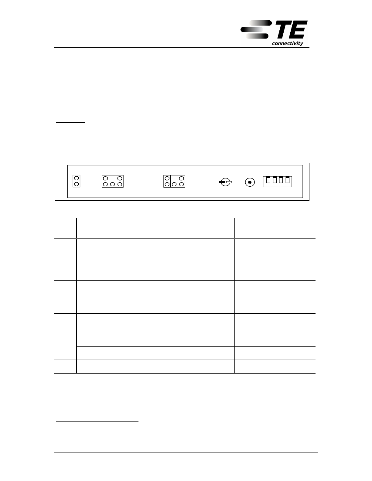
There is always an alarm when LED 1 is activated for a collective alarm.
Every other type of status in the signalling reflects normal operation in the corre-
sponding configuration.
Example: The LED 11 lights up in manual mode and selected local reversing
switches permanently when the interface is not connected. The FSAPLUS Switcher recognises the interruption of the loop on this interface.
Due to the activated local reversing switch, this information will not be
used for control. This signalling is only used for information.
LO C AL
SW ITCH
SIDE 1
SIDE 2
EX T ERNAL S W ITCHER
CE N T RAL SWIT CH ER
FCU
Top view
16
XS1
1
S2
XS4
S3
1
4
S1
Re set
Buttom
ON
OF F
1
4
DIP-switch for the
configuratio n m ode
1
2
4
3
5
6
7
8
9
10
11
12
Picture 12: Front view of the function control unit (FCU)
LED
Nº
Possible Cause of Trouble
Recommended Measures
11
X
Number of recognised moving cards (MOC) from the
central and from the external FSA-PLUS Switcher are
different.
Start switch-on procedure and
establish the recognised MOC
Replace defective MOC
all
B
1. No moving card (MOC) available
2. Ribbon cable to moving card (MOC) defective
3. Moving card (MOC) not configured
1. Install MOC
2. Replace ribbon cable
3. Configure MOC
32 or
42
B
1. Ribbon cable from the central FSA-PLUS Switcher
defective
2. Moving card in the central FSA-PLUS Switcher defective
1 Test ribbon cable
2 Start switch-on procedure
and establish the recognised
MOC ( see chapter 7.5.)
Replace defective MOC
5
X
1. External Switcher not configured correctly
2. Line disturbance or unacceptable attenuation of the
modem route
3. Control card FCU of the external Switcher defective
4. Control card FCU of the central Switcher defective
1. Configure external
Switcher again
2. Test modem line
3.& 4. Replace FCU
5 and
10
X
Line disturbance or unacceptable attenuation of the
modem route
Test modem line
6
X
Cable error on SIDE2 (automatic double mode only)
Test lines on SIDE2 for insulation and loop resistance
1
LED ”Alarm” lights up without additional LED to indicate the cause of the alarm
2
The LED flashes when there is a switching requirement in connection with an alarm. This signal-
ling means ”device cannot switch”
Page 31

FSA-PLUS Switcher (Modem Version)
Technical Manual
6341 3 103-12 - 17.05.2011
Page 31
LED
Nº
Possible Cause of Trouble
Recommended Measures
7
X
DC version: Control card (FCU) of the central
FSAPLUS Switcher defective
Replace FCU
AC version:
1. Supply voltage of the FCU too low (<14V)
2. Control card (FCU) of the central
FSA-PLUS Switcher defective
1. Separate FCU from the
plug-in power unit and
measure voltage. In the
event of voltage being too
low, replace power unit.
2. Replace FCU
B DC version only: Primary supply voltage <40.5V
Check the source of the primary supply voltage
82 or
92
B
1. Ribbon cable from the external Switcher defective
2. Moving card in the external FSA-PLUS Switcher
failed
1. Test ribbon cable
2. Start switch-on procedure
in the external Switcher
and establish the failed
MOC.
Replace defective MOC
10
X
1. Central Switcher not configured correctly
2. Line disturbance or unacceptable attenuation of the
modem route
3. Control card FCU of external Switcher defective
4. Control card FCU of central Switcher defective
1. Configure the Switcher
again
3. Test modem line
4. & 5. Replace FCU
11
X
Cable error on SIDE1 (automatic double mode only)
Test line on SIDE1 (Insulation
and loop resistance)
B Cable error SIDE1 has been detected. Now the cable
has no errors again
Test lines on SIDE 1.
12
X
DC version: Control card (FCU) of the external FSA-
PLUS Switcher defective
Replace FCU
AC version:
1. Distribution voltage of the FCU too low (<14V)
2. Control card (FCU) of the external FSA-PLUS
Switcher defective
1. Separate FCU from the
plug-in power unit and
measure voltage. In the
event of voltage being too
low, replace power unit.
2. Replace FCU
B DC version only: Primary supply voltage <40.5V
Check source of primary supply voltage
X: LED lights up permanently O: LED does not light up B: LED flashes
2
The LED flashes when there is a switching requirement in connection with an alarm. This signal-
ling means ”device cannot switch”
Page 32

Exclusion of liability
ADC GmbH shall not be liable for any damage
caused by misuse of the product and/or any use
other than described herein.
Disposal advice
Please take special note of any regulations regarding the disposal of materials.
Duplication of the technical manual is only allowed
with the permission of ADC GmbH.
ADC GmbH
Beeskowdamm 3-11
D - 14167 Berlin
Contact us at Support Center:
http://www.tycoelectronics.com/customersupport/support.asp
6341 3 103-12 DOKBI---00B
Subject to change
 Loading...