

TE Connectivity Basic AMP-O-LECTRIC K 1-471273-3, Basic AMP-O-LECTRIC K 1-471273-4 Customer's Manual
Page 1

Basic AMP-O-LECTRIC* Model “K"
Terminating Machine 471273-[ ], Main
Accessories and Most Common Modifications
Customer Manual
409-5128
17 JAN 12 Rev Z
SAFETY PRECAUTIONS
1. INTRODUCTION . . . . . . . . . . . . . . . . . . . . . . . . . . . . . . . . . . . . . . . . . . . . . . . . . . . . . . . . 3
2. DESCRIPTION. . . . . . . . . . . . . . . . . . . . . . . . . . . . . . . . . . . . . . . . . . . . . . . . . . . . . . . . . . 4
al
u
2.1. Physical Description . . . . . . . . . . . . . . . . . . . . . . . . . . . . . . . . . . . . . . . . . . . . . . . . . . 4
2.2. Functional Description . . . . . . . . . . . . . . . . . . . . . . . . . . . . . . . . . . . . . . . . . . . . . . . . 5
2.3. Vertical Reel Bracket Assembly . . . . . . . . . . . . . . . . . . . . . . . . . . . . . . . . . . . . . . . . . 6
2.4. Electrical System . . . . . . . . . . . . . . . . . . . . . . . . . . . . . . . . . . . . . . . . . . . . . . . . . . . . 7
3. RECEIVING INSPECTION AND INSTALLATION. . . . . . . . . . . . . . . . . . . . . . . . . . . . . . . 7
3.1. Receiving Inspection . . . . . . . . . . . . . . . . . . . . . . . . . . . . . . . . . . . . . . . . . . . . . . . . . 7
3.2. Factors Affecting Machine Placement . . . . . . . . . . . . . . . . . . . . . . . . . . . . . . . . . . . . 7
3.3. Installation . . . . . . . . . . . . . . . . . . . . . . . . . . . . . . . . . . . . . . . . . . . . . . . . . . . . . . . . . 10
4. OPERATION . . . . . . . . . . . . . . . . . . . . . . . . . . . . . . . . . . . . . . . . . . . . . . . . . . . . . . . . . . . 11
4.1. Hand Cycling . . . . . . . . . . . . . . . . . . . . . . . . . . . . . . . . . . . . . . . . . . . . . . . . . . . . . . . 11
4.2. Production Operation . . . . . . . . . . . . . . . . . . . . . . . . . . . . . . . . . . . . . . . . . . . . . . . . . 12
5. PREVENTIVE MAINTENANCE. . . . . . . . . . . . . . . . . . . . . . . . . . . . . . . . . . . . . . . . . . . . . 13
5.1. Cleaning . . . . . . . . . . . . . . . . . . . . . . . . . . . . . . . . . . . . . . . . . . . . . . . . . . . . . . . . . . . 13
5.2. Inspection. . . . . . . . . . . . . . . . . . . . . . . . . . . . . . . . . . . . . . . . . . . . . . . . . . . . . . . . . . 13
5.3. Lubrication . . . . . . . . . . . . . . . . . . . . . . . . . . . . . . . . . . . . . . . . . . . . . . . . . . . . . . . . . 13
READ THIS FIRST !
. . . . . . . . . . . . . . . . . . . . . . . . . . . . .2
customer man
6. TROUBLESHOOTING. . . . . . . . . . . . . . . . . . . . . . . . . . . . . . . . . . . . . . . . . . . . . . . . . . . . 16
7. ADJUSTMENTS . . . . . . . . . . . . . . . . . . . . . . . . . . . . . . . . . . . . . . . . . . . . . . . . . . . . . . . . 17
7.1. Crimp-Height/Shut-Height (Base Mount) Adjustment. . . . . . . . . . . . . . . . . . . . . . . . . 17
7.2. Feed Connecting Rod Adjustment . . . . . . . . . . . . . . . . . . . . . . . . . . . . . . . . . . . . . . . 18
7.3. Feed Mechanism Damper Screw and Rear Stop Screw Adjustment. . . . . . . . . . . . . 18
7.4. Guard Installation and Repair. . . . . . . . . . . . . . . . . . . . . . . . . . . . . . . . . . . . . . . . . . . 19
8. REPLACEMENT AND REPAIR. . . . . . . . . . . . . . . . . . . . . . . . . . . . . . . . . . . . . . . . . . . . . 21
8.1. Trip Control Box Assembly. . . . . . . . . . . . . . . . . . . . . . . . . . . . . . . . . . . . . . . . . . . . . 21
8.2. Foot Switch. . . . . . . . . . . . . . . . . . . . . . . . . . . . . . . . . . . . . . . . . . . . . . . . . . . . . . . . . 21
9. PARTS LIST AND EXPLODED VIEW DRAWINGS FOR BASIC MACHINE . . . . . . . . . . 21
10. MACHINE ACCESSORIES. . . . . . . . . . . . . . . . . . . . . . . . . . . . . . . . . . . . . . . . . . . . . . . 37
11. MODIFIED MACHINES . . . . . . . . . . . . . . . . . . . . . . . . . . . . . . . . . . . . . . . . . . . . . . . . . . 58
12. ROHS INFORMATION. . . . . . . . . . . . . . . . . . . . . . . . . . . . . . . . . . . . . . . . . . . . . . . . . . . 61
13. REVISION SUMMARY . . . . . . . . . . . . . . . . . . . . . . . . . . . . . . . . . . . . . . . . . . . . . . . . . . 61
© 2012 Tyco Electronics Corporation, a TE Connectivity Ltd. Company
All Rights Reserved
*Trademark
TE Connectivity, TE connectivity (logo), and TE (logo) are trademarks. Other logos, product and/or Company names may be trademarks of their respective owners.
TOOLING ASSISTANCE CENTER
1-800-722-1111
This controlled document is subject to change.
For latest revision and Regional Customer Service,
visit our website at www.te.com
1 of 61
LOC B
Page 2

409-5128
DANGER
STOP
SAFETY PRECAUTIONS AVOID INJURY
Safeguards are designed into this application equipment to protect operators and maintenance personnel from
most hazards during equipment operation. However, certain safety precautions must be taken by the operator
and repair personnel to avoid personal injury, as well as damage to the equipment. For best results, application
equipment must be operated in a dry, dust-free environment. Do not operate equipment in a gaseous or
hazardous environment.
• Carefully observe the following safety precautions before and during operation of the equipment:
• ALWAYS wear appropriate ear protection.
• ALWAYS wear approved eye prot ect ion w hen op e ra tin g po we re d eq u ipm e nt.
• ALWAYS keep guard(s) in place during normal operation.
• ALWAYS insert power plug into a properly grounded receptacle to avoid ele ctrical shock.
• ALWAYS turn off the main power switch and disconnect electrical cord from the power source when
performing maintenance on the equipment.
• NEVER wear loose clothing or jewelry that may catch in moving parts of the application equipment.
• NEVER insert hands into installed application equipment.
• NEVER alter, modify, or misuse the application equipment.
TOOLING ASSISTANCE CENTER
CALL TOLL FREE 1-800-722-1111 (CONTINENTAL UNITED STATES AND PUERTO RICO ONLY)
The Tooling Assistance Center offers a means of providing technical assistance when required.
In addition, Field Service Specialists are available to provide assistance in the adjustment or repair of the
application equipment when problems arise which your maintenance personnel are unable to correct.
INFORMATION REQUIRED WHEN CONTACTING THE TOOLING ASSISTANCE CENTER
When calling the Tooling Assistance Center regarding service to equipment, it is suggested that a person familiar
with the device be present with a copy of the manual (and drawings) to r eceive instructions. Many difficulties can
be avoided in this manner.
When calling the Tooling Assistance Center, be ready with the following information:
1. Customer name
2. Customer address
3. Person to contact (name, title, telephone number, and extension)
4. Person calling
5. Equipment number (and serial number if applicable)
6. Product part number (and serial number if applicable)
7. Urgency of request
8. Nature of problem
9. Description of inoperative component(s)
10. Additional information/comments that may be helpful
Rev Z
2 of 61
Page 3
409-5128
Figure 1
1. INTRODUCTION
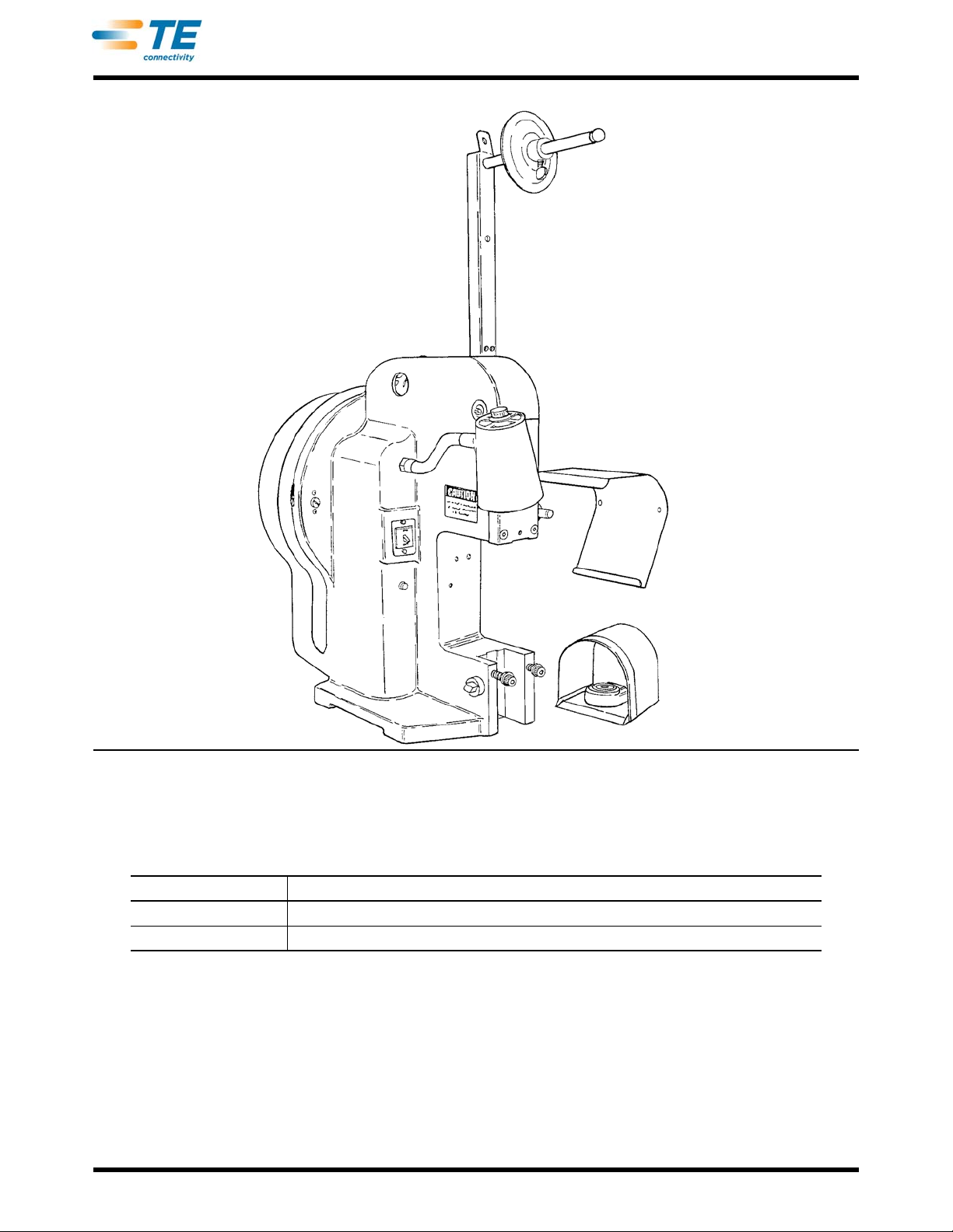
This manual covers basic AMP-O-LECTRIC Model "K" Terminating Machine 1-471273-3 and 1-471273-4
(shown in Figure 1), main accessories, and most common modifications.
MACHINE NUMBER MACHINE DESCRIPTION
1-471273-3 115 Vac, 60 Hz, and comes with Mechanical Feed Option 692140-2 factory installed
1-471273-4 230 Vac, 50 Hz, and does NOT include Mechanical Feed Option 692140-2
The machine is used to power the applicator that applies strip-fed terminals to wire. In addition, the machine is
also used as the principal component in other special application equipment covered in separate customer
manuals. These manuals refer to this one for basic machine information and parts.
Sections 1 through 9 provide a machine description and infor
troubleshooting, adjustment, repair, and parts replacement. Section 10 covers the accessories used to modify
the basic machine to a different configuration. When the acces so rie s are factor y installed, th e ma ch in e part
number on the nameplate changes from the basic number to one identifying the modified configuration. Section
11 discusses these modified configurations by part number. The accessories are also available as kits for field
conversion, in which case the machine part number will no longer identify the configuration.
Rev Z
mation on its installation, operation, maintenance,
3 of 61
Page 4
409-5128
DANGER
STOP
!
CAUTION
NOTE
i
NOTE
i
Packaged with every applicator is a parts list identifying the required machine number for that applicator. The
parts list also identifies the accessories necessary to convert the machine to the required configuration.
The basic machine is fitted to accept standar d applicators, which are semi -permanently mounted to the machine
for production of one size and type of terminal witho ut the ne ed for fre qu ent ch an ge o ve r of ap plic at or s or
changes in the applicator crimp height. The most frequent field conversion is a kit to adapt the ma chine for
miniature quick-change applicators, which are easily installed and removed and allow simple adjustment of the
crimp height. Instruction sheet 408-8022 provides a parts list for the kit and the necessary instructions for
converting a basic machine for standard applicators to miniature quick-change applicators.
An instruction sheet, packaged with each applicator, provides
adjustment. The instruction sheet, the applicator parts list, and this manual collectively provide complete
documentation for the various production setups involving applicators and the Model "K" terminating machine.
When reading this manual, pay particular attention to D
information on applicator installation, care, and
ANGER, CAUTION, NOTE statements.
Denotes an imminent hazard which may result in moderate or severe injury.
Denotes a condition which may result in product or equipment damage.
Highlights special or important information.
Dimensions in this manual are in metric units [with U.S. customary units in brackets].
Reasons for reissue of this document are provided in Section 12, REVISION SUMMARY.
See Figure 2 for specifications for the machine.
DIMENSIONSs:
Height 610 mm [24 in.]
Width 533 mm[ 21 in.]
Depth 508 mm [20 in.]
WEIGHT
Basic machine without aplicator 104 Kg [230 lbs]
POWER REQUIREMENTS
Electrical (1-471273-3) 115 Vac, single phase with separate ground, 60 Hz, 6 Amps
Electrical (!-471273-4) 230 Vac, single phase with separate ground, 50 Hz, 3 Amps
Air (if used) 552-827 kPa [80 - 120 psi]
Figure 2
2. DESCRIPTION
2.1. Physical Description
The basic machine consists of a cast-iron frame with a flywheel gua rd in back tha t is hinged to the fr ame. Inside
the guard is a 1/4-hp motor, flywheel assembly, transmission assembly, toggle lever, and feed actuating
components. Mounted on the right side of the frame, facing the operator, is the feed arm drive shaft and the
Rev Z
4 of 61
Page 5
409-5128
Transmission Operation
To Solenoid
Stop Bar (Pawl)
Clutch Dog
(Sliding Key)
Toward Front of
Machine
Shaft
Center Line
Backup Latch
(Pawl)
Cam
Lobe
Stop Collar
Dog Retainer
Support
Drive Plate
(On Flywheel)
Dog Wedge Ramp
Machine in REST Position
vertical reel bracket assembly. The electrical system consists of a main power switch, work lamp, and panel light
located on the left front of the machine; a trip control box assembly inside the back cover; a foot switch; and
electrical wiring. The motor is bolted to a mounting plate that is hinged to the machine frame by a support pin.
The weight of the motor provides enough tension to the V-belt for driving the flywheel.
The basic machine does not contain a ram or base mount. These are supplied with the applicator or the
conversion kit. The ram is mounted behind the ram retaining plate on the front of the frame.
The frame contains holes for bolting the machine to a bench
in Section 3.
at a height convenient for the operator as describ ed
2.2. Functional Description
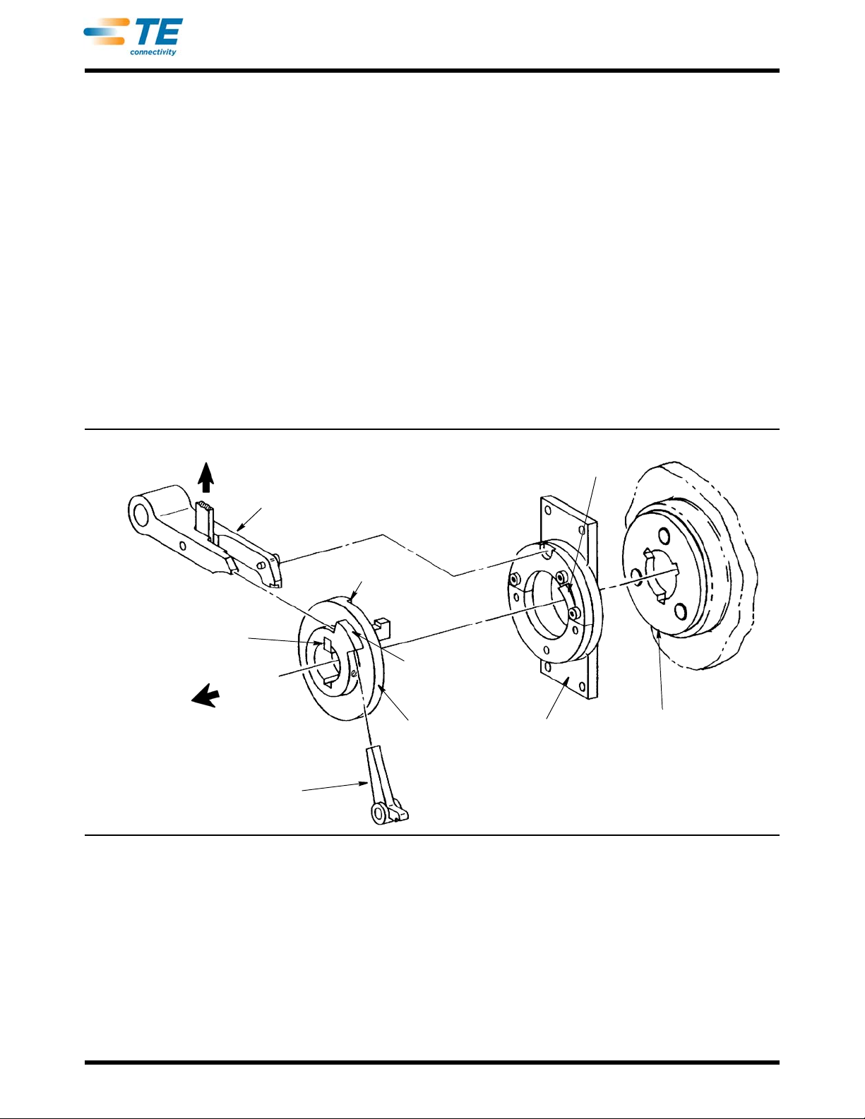
The motor-flywheel assembly runs continuously when the control switch is "on." The flywheel turns on the main
shaft of the transmission until the foot switch is depressed to actuate the solenoid on the transmission. The
energized solenoid pulls up the stop bar (see Figure 3) to release the clutch dog (slid ing key), which is then
forced toward the flywheel by spring pressure. The end of the clutch do g then slides into the first opening it
encounters in the drive plate on the rotating flywheel. This connects the rotating flywheel and the drive shaft to
start the machine cycle.
At approximately 270° in the rotation cycle, the beveled forward ed ge of the notch in the clutch dog encounters
the
dog wedge ramp on the face of the dog retain er support. As the clutch dog slides up this ramp against sp ring
pressure, it is withdrawn from the flywheel drive plate.
During the cycle, the cam on the rear face of the stop collar rides over the pin on the rear finger of the stop bar,
forcing it down to retain the clutch dog in the rest position at the end of the cycle . This brings the end of the front
finger of the stop bar in position to contact one side of the lobe on the front of the stop collar to prevent further
forward rotation of the drive shaft. At the same time, spring tension forces the backup latch in against the
opposite side of the lobe on the stop collar to prevent reverse rotation.
An eccentric arm is keyed to the forward end of the main shaft (see Figure 9). The arm is at TOP-DEADCENTER
the toggle lever subassembly.
Rev Z
when the machine is in the rest position. Attached to the arm is a spherical bearing link that actuates
Figure 3
5 of 61
Page 6
409-5128
To Feed Actuating
Mechanism
Ram “Down”
Toggle Arm Pin
Pivot
Pins
Crimping Position
Spherical
Bearing Link
Toggle
Link
Toggle
Lever Clevis
Ram “UP"
Down
Up
Toggle
Lever
Rest Position
Toggle Lever Subassembly Operation
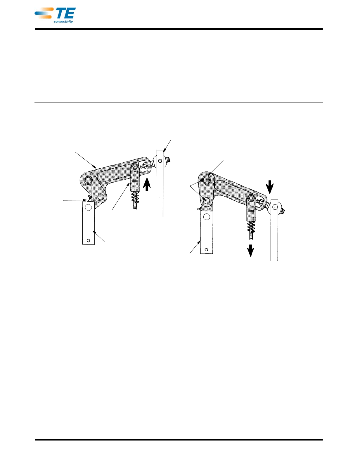
The toggle lever subassembly is secured in the frame by the toggle arm pin at the front (see Fig ure 4). This pin
acts as the pivot point. Another pin connects the link to the lever, and the opposite end of the link is connected to
the ram by a pin.
The feed actuating mechanism (see Figure 13) is driven by the toggle lever. The feed connecting rod is joined to
the toggle lever by a pin and clevis. A compression spring is installed over the connecting rod, extending from
the clevis to the feed actuating block at its lower end. The spring absorbs the overaction and a llows for feed
adjustment. The feed actuating arm joins the feed actuating block on it s inner end, and the feed arm drive shaft
on the outer end, to oscillate the shaft in the bracket attached to the frame. The upward travel of the arm is
limited by the forward stop screw and its downward travel by the damper screw.
Figure 4
The feed actuating mechanism is used to drive the feed arm assembly when using standard applicators that
require a mechanical feed or for operating air valves for air feed and air blasts (when installed). These
assemblies are covered in Section 10.
2.3. Vertical Reel Bracket Assembly (Figure 18)
The vertical reel bracket assembly, supplied with the machine, is adaptable to the broadest range of reel bracket
requirements. Three locations for the reel shaft on the vertical bracket allow mounting of all sizes of vertically
mounted reels. By changing the shaf t to the in clined t ab on top of the ve rtical reel supp ort, conical reels can al so
be installed. From either location of the reel shaft, the terminal strip is fed around the stock guide and into the
applicator from the right side of the machine.
When using the vertical reel bracket assembly for feedin
bracket must be tilted downward. This is accomplished by moving the left screw to the upper mounting hole in
the vertical reel support.
The assembly also adapts to feed the terminal strips into a
miniature side-feed applicators, and into applicators mounted at a 30_ angle, with the use of available
assemblies (see Section 10).
Rev Z
g miniature end-feed applicators, the stock guide
pplicators from the left side of the machine for
6 of 61
Page 7

409-5128
NOTE
i
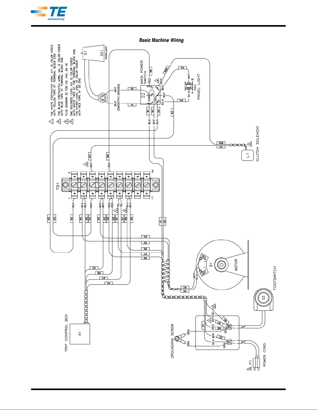
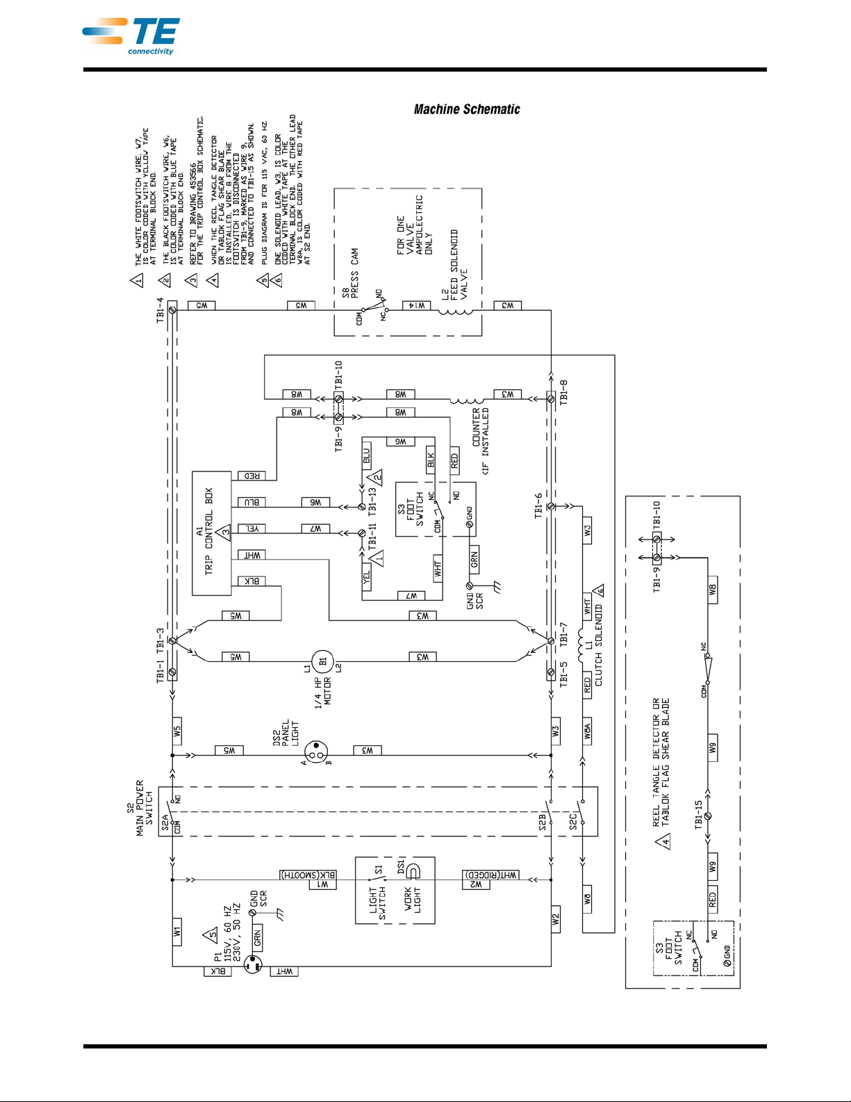
2.4. Electrical System (Figure 5 and Figure 6 )
The electrical system of the basic machine consists of a motor, trip control box, transmission solenoid, foot
switch, barrier strip, main power (control) switch, work lamp, panel light, and wiring. The basic electrical system
may be modified when adapted for special applications.
The machine must be connected to an adequate electrical outlet.
current specifications. The electrical current is supplied directly to the double-pole, single-throw main power
switch (S2) and to the work lamp (DS1) which contains an integral switch (S1). Power from the main power
switch, when placed in the "on" position, is supplied to the barrier strip (TB1) and to the panel light (DS2). From
the barrier strip, power is supplied to the motor (B1), which runs continuously when the control (main) switch is
"on."
The trip control box (A1) and transmission solenoid (L1) are connected to the barrier strip and are controlled by
the
foot switch (S3). When the foot switch is depressed, it activates the trip control to provide a pulse of electric
current to energize the solenoid. The solenoid will not energize again until the foot switch is released, then
depressed again. This prevents double-cycling of the machine.
Some applicators require an interlock switch. The switch is
transmission solenoid to prevent the solenoid from being energized until the switch is mechanically actuated.
Basic machine wiring is shown in Figure 5 and the ele
For accurate, up-to-date drawings, see the drawings shipped with the machine.
ctrical schematic is shown in Figure 6.
Refer to Figure 2 for machine voltage and
wired in series between the trip control box and the
3. RECEIVING INSPECTION AND INSTALLATION
3.1. Receiving Inspection
These machines are thoroughly inspected during and afte r assembly. A final series of inspections is made to
ensure the proper functioning of each machine before packaging and shipping.
However, dam age may occur during shipment. While unpacking the machine, remove the outer bands from the
car
ton or crate, lift off the outer box, and CAREFULLY inspect the complete mach ine for damage. If damage is
evident, file a claim against the carrier and notify Tyco Electronics Corporation, Harrisbu rg , Pen n sylva n ia.
3.2. Factors Affecting Machine Placement
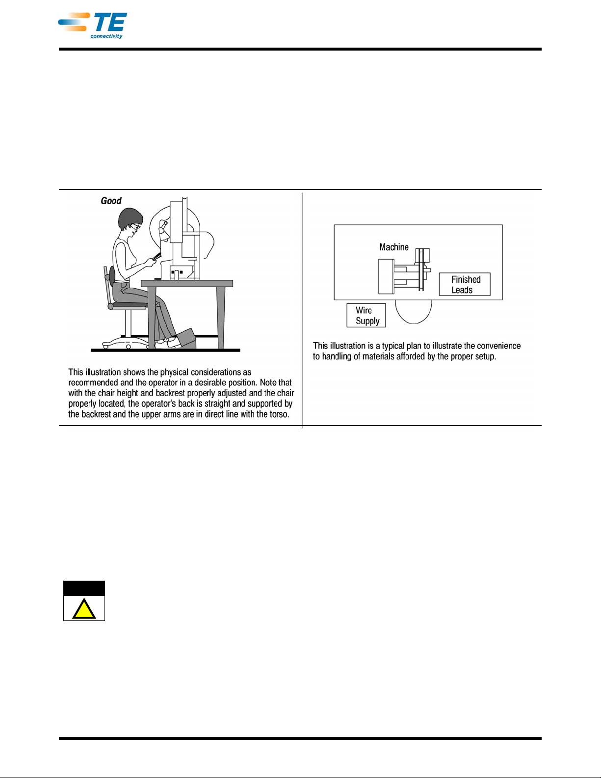
The location of the machine in relation to the operator is essential to both safety and efficiency. Studies have
repeatedly shown that fatigue will be reduced and efficiency increased if particular attention is paid to the bench,
the location of the machine on the bench, the operator's chair, and the placement of the foot switch (see
Figure 7).
A. Bench
A sturdy bench 711 to 762 mm [28 to 30 in.] high aids comfort by allowing the operator's feet to rest on the
floor and the weight and leg position to be easily shifted. The bench should have rubber mounts to reduce
noise. An open area under the bench should allow the chair to slide far enough in for the operator's ba ck to be
straight and supported by the chair backrest.
B. Machine Location on the Bench
The machine should be located near the front of the bench and secure ly bolted to remain stationary. The
target area (tooling area where the term inal is applied) should be 152 to 203 mm [6 to 8 in.] from the front
edge. This eliminates unnecessary operator motion and help s prevent back strain and fatigue . The target area
should face the front of the bench and be parallel to the e dge (access to the back of the machine must also b e
provided).
C. Operator's Chair
The operator's chair should swivel, and the seat and backrest should be padded and independently
adjustable. The backrest should be large enough to support the back bo th above and below the waist. In use,
the chair should be pulled far enough un der the bench so th at the operator's back is str aight and supported by
the backrest.
Rev Z
7 of 61
Page 8
409-5128
Rev Z
Figure 5
8 of 61
Page 9
409-5128
Rev Z
Figure 6
9 of 61
Page 10
409-5128
CAUTION
!
D. Foot Switch
When the operator is correctly positioned in front of the machine, the foot should rest on the switch
comfortably and easily. The switch should be placed on a ru bber mat: this allows it to be movable and permit s
the operator to shift positions to reduce fatigue, while at the same time the mat prevents the switch from
sliding unintentionally.
The preference for locating the switch varies among operator
rests on the switch when their leg is in the natural sitting position (calf perpendicular to the floor). Others
prefer it slightly in front of the natural position. The important thing is that the foot be about 90_ to the calf
when resting on the switch. Those who prefer the switch slightly forward may require a wedge -shaped block
placed under it.
s. Some like the switch located so that their foot
Figure 7
3.3. Installation
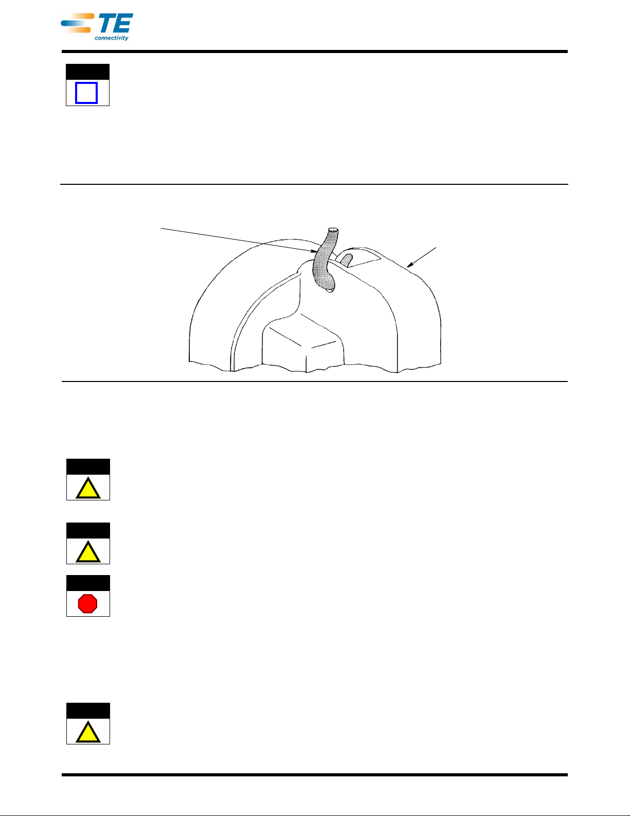
The machine is bolted to the shipping pallet. Cut away the remaining carton, remove the bolts securing it to the
pallet, then remove the yellow plug and top access hole cover. Attach the hook of an adequate hoist to the
machine, as shown in Figure 8, to lift it from the pallet and place it in the selected location. The approximate
weight of a complete machine is 123 Kg [272 lb.].
Place the machine on a sturdy bench conforming to the req
the necessary electrical supply (with a separate ground) and, for air-equipped machines, the necessary air
supplies. A 1/4-in. NPT male fitting is required to connect the air to the machine.
Do NOT connect the machine to the electrical outlet, or to the air, until specified. The adequacy of both the electrical
power and air supply should be checked at the machine location..
Install a 40-watt appliance bulb, of the proper volt
damage the shade. Position the foot switch on the floor convenient for the operator.
BEFORE connecting the machine to the electric source and a
in Paragraph 4.1 to ensure proper alignment and adjustment of tooling in the applicator (if installed) to prevent
damage.
age rating, in the work lamp. A bulb of greater wattage will
uirements in Paragraph 3.2. The location must have
ir supply, hand-cycle it according to the procedure
Rev Z
10 of 61
Page 11
NOTE
i
409-5128
Hoist Hook
Frame with Top Access
Hole Cover Removed
Hoisting Method
CAUTION
!
CAUTION
!
DANGER
STOP
CAUTION
!
When machines are shipped with an applicator installed, an attached package will contain an envelope with crimped
product samples which will be to the customer's specifications. These samples should be used as a comparison. All
significant test results are recorded on the applicator parts list, included in the envelope, and were made under power.
Examination of the complete machine
recommended, after which it should be securely bolted to the bench to prevent movement during operation.
Perform several test cycles under power using the procedure s
Paragraph 4.2.
for evidence of loose screws, bolts, and other components is
pecified for production operation in
Figure 8
4. OPERATION
The machine is easy to operate, providing it is properly adjusted (see Section 7) and the applicator is also
properly adjusted (see applicable instruction sheet).
BEFORE connecting the machine to electrical power, and to the air supply, hand-cycle it to check for proper alignment of
tooling to prevent possible damage.
4.1. Hand Cycling (Figure 9)
MAKE SURE main switch is "off" and electrical plug is disconnected, unless otherwise specified.
To avoid personal injury, ALWAYS disconnect electrical and air supply before removing flywheel guard.
1. Open flywheel guard to gain access to transmission and flywheel.
2. Manually close solenoid by raising stop bar. This will allow c
during rotation.
3. By hand, slowly turn flywheel in the direction of th
the rear of the machine).
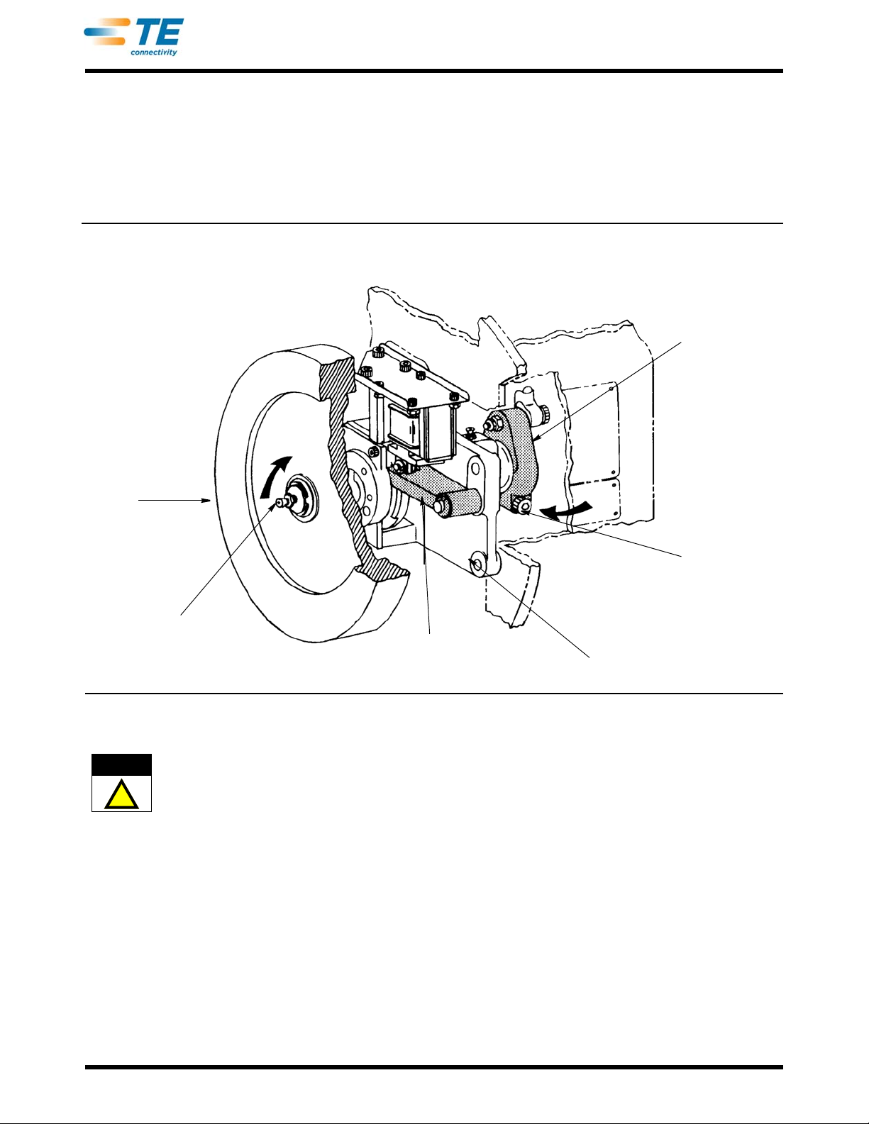
DO NOT ATTEMPT to turn flywheel backward (counterclockwise), since this may damage or jam the applicator.
lutch dog to engage in drive plate on flywheel
e arrow as shown in Figure 9 (clockwise, as viewed from
Rev Z
11 of 61
Page 12
409-5128
Hand-Cycling of Machine
Eccentric Arm
Grease Fitting on
Flywheel
Crankshaft Mount
Stop Bar
Grease Fitting on
End of Crankshaft
Flywheel
CAUTION
!
4. As the machine ram nears the bottom of the stroke, closely observe tooling for proper alignment. If
misalignment is evident, STOP rotation of flywheel and determine cause. If adjustment to machine is r equired,
see Section 7. If adjustments to the applicator are required, refer to the appropriate instruction sheet. If
machine is for a special application, see the appropriate customer manual.
5. To reset the machine, use a 7/16-in. wrench to turn the grease fitting on the end of the crankshaft in the
direction of the arrow as shown in Figure 9. Use a crescent wrench or 7/16-in. box end wrench to turn the
grease fitting on the flywheel in the direction of the arrow also shown in Figure 9.
Figure 9
4.2. Production Operation
Operation of the machine may vary slightly depending on the application for which it is used. Should procedures
contained in the instructions for the applicator or other customer manuals dif
take precedence over this manual.
1. Connect electrical plug to an outlet with separat
connection.
2. Make sure machine is at TOP-DEAD
run continuously.
3. Perform several test
depressing the foot switch, and then releasing it before another cycle can be performed.
4. Perform production operation in the same manner as descr
to ensure proper crimping of terminals.
5. At end of production operation, move main switch to
Disconnect electrical plug.
cycles to check machine for proper operation. Each cycle is accomplished by
-CENTER, and then move main switch (S2) to ON. Motor will start and
e ground connection. If an air supply is used, make
ibed in Step 3. Take periodic inspection samples
OFF, and turn air supply OFF (if applicable).
fer from the following procedure, they shall
Rev Z
12 of 61
Page 13
409-5128
DANGER
STOP
DANGER
STOP
DANGER
STOP
5. PREVENTIVE MAINTENANCE
Preventive maintenance is cleaning, inspecting, and lubricating the machine to keep it in continuous operation. It
is suggested that a regular maintenance program be establish ed and followed to eliminate the cost of
unnecessary repairs. For applicators and special applications of the machine, refer to the publications supplied
with them.
To avoid personal injury, ALWAYS disconnect electrical and air supply before performing preventive maintenance.
Re-install ALL dust caps removed during maintenance, to prevent possible injury.
5.1. Cleaning
1. Using a CLEAN, dry cloth, wipe the entire machine to remove any dust or other foreign matter from
accessible areas.
2. Using a solvent or similar cleaning fluid, remove any oil or grease from machine.
3. Using an air hose, blow out any chips and met al particles
area.
Compressed air used for cleaning must be reduced to less than 206.8 kPa [30 psi], and effective chip guarding and
personal protective equipment (including eye protection) mu
that may be in the machin e, especially in the work
st be used.
5.2. Inspection
1. Inspect entire machine for loose components and hardware.
2. Inspect electrical wiring for loose connections,
chafing, and broken wires or insulation.
3. Inspect moving parts for evidence of excessive wear.
4. Inspect machine for proper lubrication. If nece
ssary, lubricate in accordance with Paragraph 5.3.
5.3. Lubrication
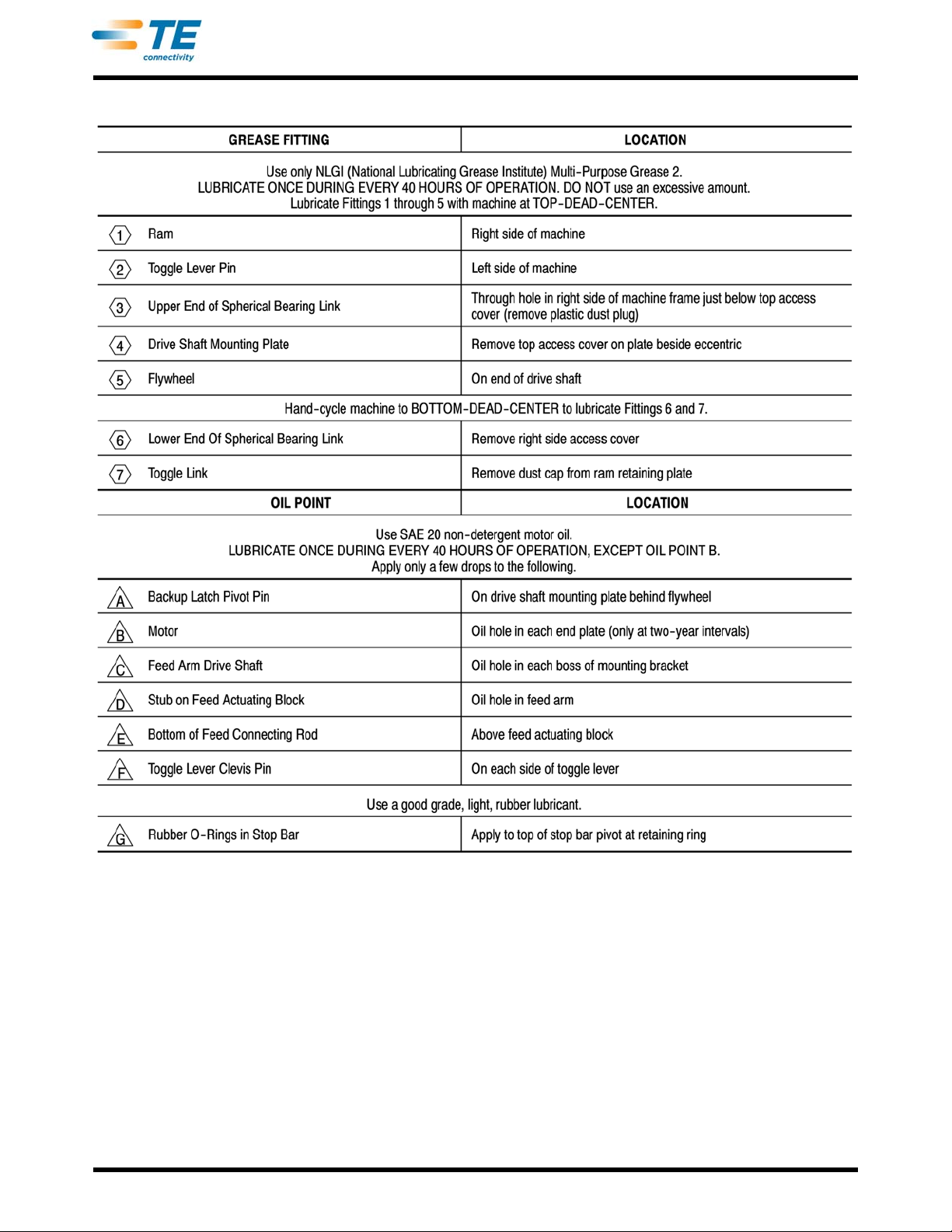
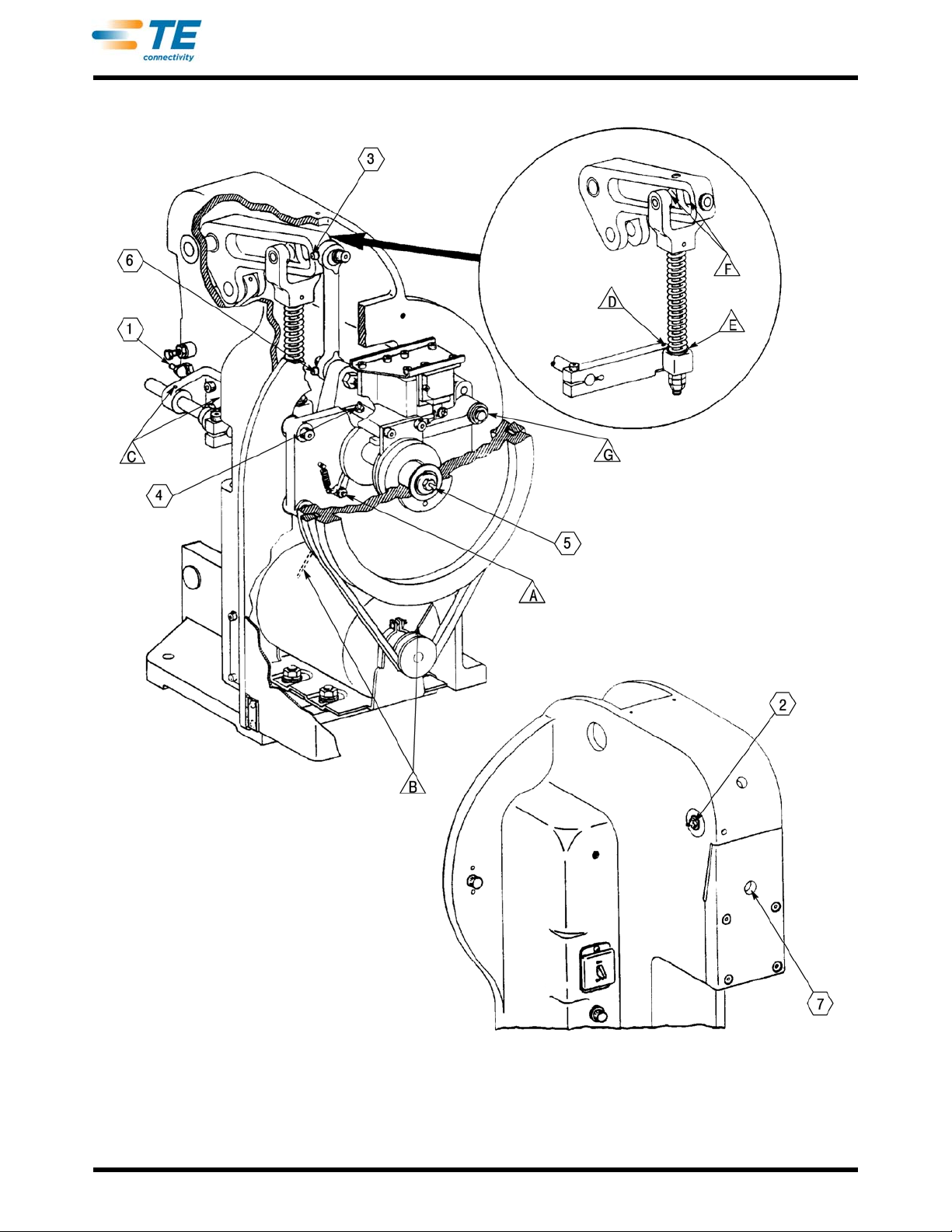
Lubricate the machine according to the tabulation and at the points indicated in Figure 10.
Rev Z
13 of 61
Page 14
409-5128
Rev Z
Figure 10 (Cont’d)
14 of 61
Page 15
409-5128
Rev Z
Figure 10 (End)
15 of 61
Page 16

409-5128
6. TROUBLESHOOTING
Figure 11 is presented in order of normal sequence. The second column lists the probable cause s in the order
most likely to occur and be checked. The third column lists the remedy for each of the probable causes and
references to other parts of the manual that should be helpful in remedying the problem.
TROUBLE PROBABLE CAUSE REMEDY
1.Motor does not run when main switch
(S2) is moved to ON.
2.Motor runs, but machine does not
ycle when foot switch is depressed.
c
3.Transmission does not engage when
olenoid is energized.
s
4.Machine does not return to TOP-
DEAD-CENTER after cycling under
wer.
po
5.Machine continues to cycle with foot
witch depressed or released.
s
6.Transmission does not lock at TOP-
DEAD-CENTER whe
n in rest position.
Electrical plug disconnected or no power to
outlet.
If panel light is not illuminated, switch or power
cord defective.
If panel light is illuminated, check for loose
wiring connections at switch, barrier strip, and
motor.
Defective wiring between switch and motor.
Defective motor. Replace motor. Refer to Section 9.
Machine not at TOP-DEAD-CENTER (rest
po
sition).
Check for loose wiring connections at barrier
p.
stri
Defective foot switch. Replace foot switch. Refer to Section 9.
Defective trip control.
Defective solenoid on transmission. Replace solenoid. Refer to Section 9.
Defective transmission. See TROUBLE 4
Machine did not return to TOP-DEAD-CENTER
(res
t position).
Disconnect or broken linkage between solenoid
nd stop bar.
a
Clutch dog (sliding key) binding on shaft. Lubricate machine. Refer to Paragraph 5.3.
Broken spring behind clutch dog (sliding key). Replace spring. Refer to Section 9.
Clutch dog (sliding key) in transmission, or drive
p
late on flywheel excessively worn.
If feed arm assembly is installed, forward stop
screw is se
Binding or defective applicator.
Less than two washers in front of top spherical
earing link.
b
Seized pins in toggle lever-feed actuating
c
omponents.
Defective O-rings in stop bar. Replace O-rings. Refer to Section 9.
Defective or broken stop bar in transmission. Replace stop bar. Refer to Section 9.
Loose or worn stop collar in transmission.
Worn dog wedge in transmission. Replace dog wedge. Refer to Section 9.
Backup latch or spring disconnected or broken.
Stop bar or O-rings worn or broken. Replace stop bar or O-rings. Refer to Section 9.
t too low.
Figure 11
Insert plug or check power to outlet.
Replace switch or power cord. Refer to Section
9.
Connect wiring as required. Refer to
Figure 5.
Replace wiring as required. Refer to
Figure 5.
Hand-cycle to TOP-DEAD-CENTER. Refer to
Paragraph 4.1.
Connect wiring as required. Refer to
Figure 5.
Replace trip control. Refer to
Paragraph 8.1.
Turn power off and hand-cycle machine to TOPDEAD-CENTER. Refer to
Paragraph 4.1.
Repair or replace linkage. Refer to
Section 9.
Remove flywheel and inspect parts for rounded
edges. If necessary, replace parts. Refer to
Section 9.
Make adjustments as required. Refer to Section
10.
Repair or adjust applicator. Refer to applicator
instruction sheet.
Add washer(s). Refer to Section 9.
Lubricate machine and if necessary, replace
parts. Refer to Paragraph 5.3 and Section 9.
Replace stop collar and lubricate. Refer to
Section 9.
Repair or replace latch or spring. Refer to
Section 9.
Rev Z
16 of 61
Page 17
409-5128
DANGER
STOP
Frame
Adjusting Screw
Base Mount Retaining
Cap Screws
Base Mount (Ref)
CAUTION
!
7. ADJUSTMENTS
The following adjustments are required to maintain the machine in continuous operation and to set it up after
replacement of parts.
To avoid personal injury, ALWAYS disconnect the electrical and air supply, before performing any adjustment, unless
otherwise specified.
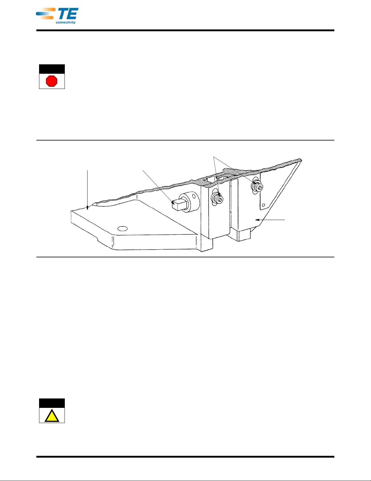
7.1. Crimp-Height/Shut-Height (Base Mount) Adjustment (Figure 12)
Although essential to operation, the base mount is no t supp lied with the ba sic machine, bu t ra ther with standard
applicators, conversion kits, some modified machines (see Section 11), and some for special applications. In all
cases, reference is made to this manual for adjustment procedures, thereby eliminating the need to duplicate
them in applicator instruction sheets and in other customer manuals.
Figure 12
Adjustment of the base mount determines the distance between the base mount and the ram at the bottom of
the stroke (half cycle of the machine). This adjustm en t controls the crimp height of terminations produced in
standard applicators, and the shut height of the machine for miniature ap plicators.
For the standard applicators, the main part, including the lowe
r tooling, is attached to the base mount. The
independent upper tooling is attached to the machine ram. Raising or lowering the base mount, then, will change
the distance (and the resulting crimp height) between the upper and lower tooling at the bottom of the ram
stroke.
Machines shipped from the factory with the base mount inst
alled for a particular application have the base
mount adjusted and the two retaining caps screws secured to discourage further adjustment. Only when it is
necessary to replace parts, or when converting the machine to another configuration, should adjustment be
required.
The miniature quick-change applicator has the upper tooling, lower
relationship all incorporated in an integrated assembly. This type applicator requires a fixed shut height. In other
words, the distance between the base mount and ram at the bottom of the stroke is a given dimension not
subject to change. The required changes in crimp height are made by using the adjusting means (wire and
tooling, and the means for adjusting their
insulation discs) within the applicator.
If the machine is set up for miniature applicators, NEVER attempt to adjust the shut height without FIRST trying another
applicator that is known to produce terminations of the
correct crimp height. If this applicator produces correct
terminations, the trouble is in the original applicator-and shut height MUST NOT BE CHANGED.
With a properly adjusted applicator installed in the machin
e, and loaded with terminals as described in the
applicator instructions, adjust for correct crimp height/shut height as follows:
Rev Z
17 of 61
Page 18

CAUTION
!
409-5128
NOTE
i
When specified to loosen the two base mount retaining cap screws in the following procedure, ALWAYS remove any
clearance between the adjustment block and the base mount by turning the adjusting screw COUNTERCLOCKWISE, as
viewed from left side of the machine.
If the crimp height of the terminal is KNOWN to be GREATER than the specified crimp height, omit Steps 1 and 2;
otherwise perform ALL steps.
1. Loosen the two base mount retaining cap screws, and lower the base mount to lowest position by rotating
th
e adjusting screw clockwise, as viewed from left side.
2. After base mount has been lowered, tighten the base mount screws to secure it to frame.
3. Insert a wire of the proper gage into the lead termina
cycle.
4. Check crimp height of termination (for the method of
greater than specified for the type terminal and wire size being used (refer to the data plate on applicator or to
the applicator parts list), continue with Step 5. If correct, continue with Step 6.
5. Loosen the two base mount retaining cap screws, then raise base mount by turning the adjusting screw
counterc
0.41 mm [.016 in.]. Tighten the base mount screws, and repeat Steps 3 and 4.
6. After producing terminations of the correct crimp he
under power to ensure crimp height is correct. If not, make further adjustment by repeating Steps 3 and 4.
lockwise, as viewed from left side, one-quarter turn. This will raise the base mount approximately
l, and hand-cycle the machine through one complete
measurement, refer to 408-7424. If crimp height is
ight by hand-cycling machine, produce terminations
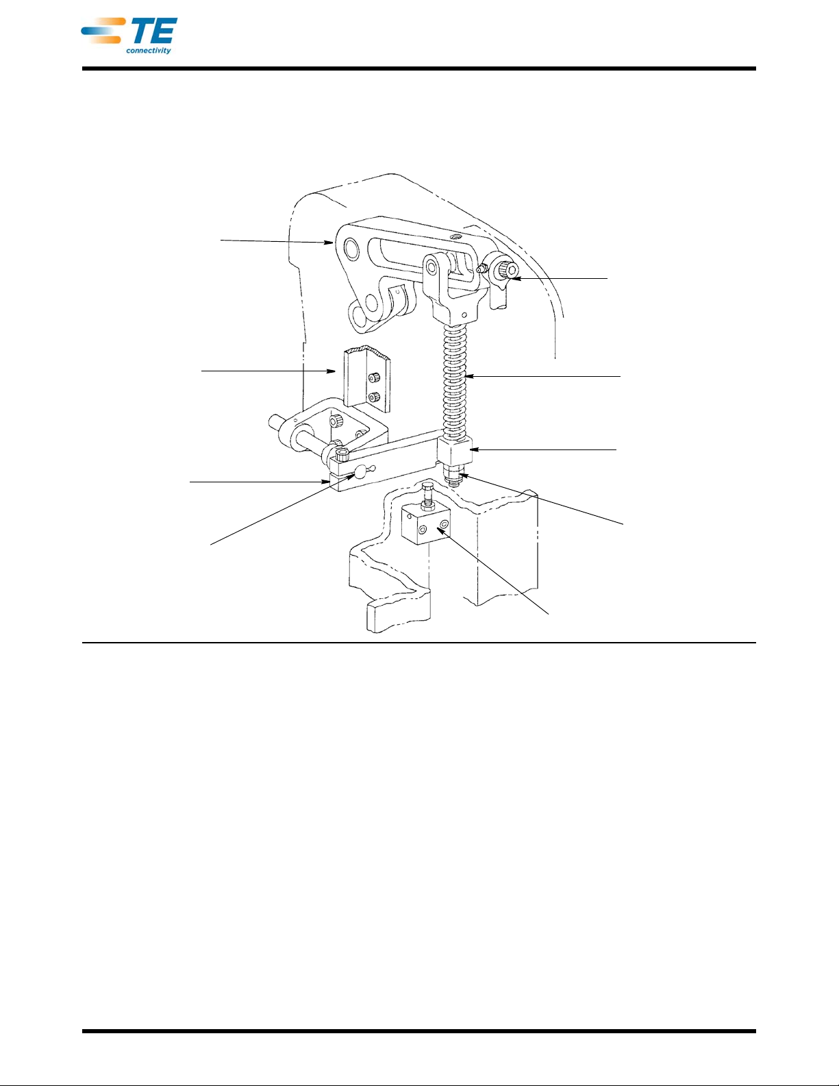
7.2. Feed Connecting Rod Adjustment (Figure 13)
Adjustment of the feed connecting rod is not critical, a nd sh ou ld n ever r equire adjustment unless it is necessary
to replace parts between the feed actuating arm and tog gle lever. Adjustment is made by means of the adjusting
locknuts under the feed actuating block. When properly adjusted, three threads of the feed connecting rod are
exposed below the tightened locknuts.
7.3. Feed Mechanism Damper Screw and Rear Stop Screw Adjustments (Figure 13)
Although the damper screw and rear stop screw ar e supplied with the basic mach ine, they are used only with the
mechanical feed arm assembly (which is available as an accessory). When the feed arm assembly is not
installed, both screws are turned all the way in and secured with th eir jam nuts.
Should adjustment be required, see Paragr ap h 10.1 .
Rev Z
18 of 61
Page 19
Feed Actuating Mechanism
Toggle Lever
Subassembly (Ref)
Vertical Reel Bracket
Assembly
Feed Actuating Arm
Spherical Bearing Link
Feed Connecting Rod
and Spring
Feed Actuating Block
Adjusting Locknuts
Damper Screw and Block
Feed Arm Drive Shaft
409-5128
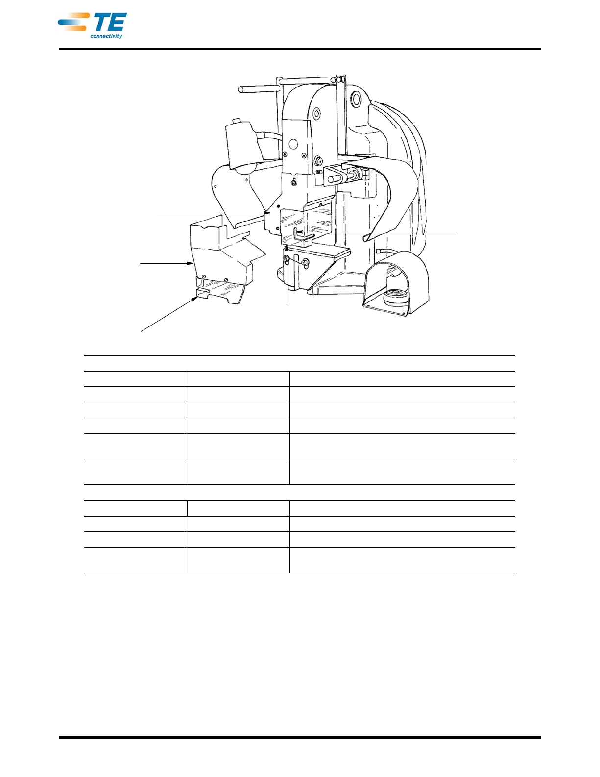
7.4. Guard Installation and Replacement (Figure 14)
The "K" terminator is supplied with guarding for the most popular of AMP's end-feed and side-feed applicators.
The guarding consists of a metal shroud and a clear, plastic guard. Some applications require a special guard,
which may or may not be shipped with the terminal applicator. In some cases, the applicator log sheet (shipped
with the applicator) lists the guard required on the parts list. Check this log first to determine if it is specified. If it
is not, refer to the table in Figure 14 for a list of common inserts. If your application falls ou tside the options listed
in Figure 14, contact the Tooling Assistance Center to determine the correct guard required.
To install the correct plastic guard, remo
the metal shroud. Take care to note their positions for correct reinstallation. Replace the plastic guard with the
correct guard for your application and reinstall the fastener hardware to secure it in position with the access slot
aligned to the applicator.
Figure 13
ve the screws, spacers, washers, and nuts holding the plas tic guard to
Rev Z
19 of 61
Page 20
Wire Access Slot
Side-Feed Guard
End-Feed Guard
End-Feed
Shroud
Side-Feed
Shroud
409-5128
COMMON END-FEED APPLICATOR GUARDS
INSERT PART NUMBER OPENING SIZE (mm [In.]) DESCRIPTION
455745-1 6.35 [.250] Standard guard - insulation diameters up to Ø6.35 [.250]
457352-1 9.53 [.375] Insulation diameters from Ø6.35 [.250] to Ø9.53 [.375]Ø
457353-1 6.35 [.250] For terminals taller than 6.35 [.250]
455750-7 9.53 [.375]
455750-8 6.35 [.250]
COMMON SIDE-FEED APPLICATOR GUARDS
INSERT PART NUMBER OPENING SIZE (mm [In.]) DESCRIPTION
455749-1 6.35 [.250] Standard guard - insulation diameters up to Ø6.35 [.250]
457373-1 9.53 [.375] Insulation diameters from Ø6.35 [.250] to Ø9.53 [.375]
457910-1 9.53 [.375]
Air feed applicators - insulation diameters up to Ø6.35 [.250]
cludes new shroud.
In
Air feed applicators - insulation diameters Ø6.35 [.250] to
3 [.375] Includes new shroud.
Ø9.5
Insulation diameters from Ø6.35 [.250] to Ø9.53 [.375]
and terminal heights from 9.65 [.38] to 12.7 [.50]
Figure 14
Rev Z
20 of 61
Page 21

8. REPLACEMENT AND REPAIR
DANGER
STOP
CAUTION
!
NOTE
i
To avoid personal injury, ALWAYS disconnect electrical and air supply before attempting any repairs or replacement of
parts.
409-5128
The procedures in this section cover those items not sh
detailed instructions for repair or replacement of internal parts. Other repairs or replacem e nts can be ma de by
referring to the applicable parts lists and exploded views in Section 9.
Each parts list, and corresponding exploded view, numerically lists all replaceable items in the order of
d
isassembly. The parts lists and exploded views begin with the complete machine in Figure 15, and continue to
provide a complete breakdown through referenced figures for subassemblies.
A CAREFUL study of the exploded views will save much time by
installation) of items not required to gain access to items being repaired or replaced.
After replacement of any parts or subassemblies, refer to Section 7 for necessary adjustments before operating the
machine under power.
own disassembled in Section 9 but which require
eliminating the unnecessary removal (and re-
8.1. Trip Control Box Assembly Replacement (Figure 17)
1. Gain access to trip control box assembly (Item 12, Figure 17) by opening flywheel guard.
2. Disconnect wires from trip control
3. Remove assembly from the cover attached to the frame by removing two screws on top. It is not necessary
remove the cover.
to
4. Install trip control bo
wiring.
x assembly by reversing removal procedure. If necessary, see Figure 5 for machine
box assembly at the barrier strip.
8.2. Foot Switch (Figure 17)
In the event of a defective foot switch (Item 22), a replacement foot switch can be installed. Refer to the wiring
diagram in Figure 5,
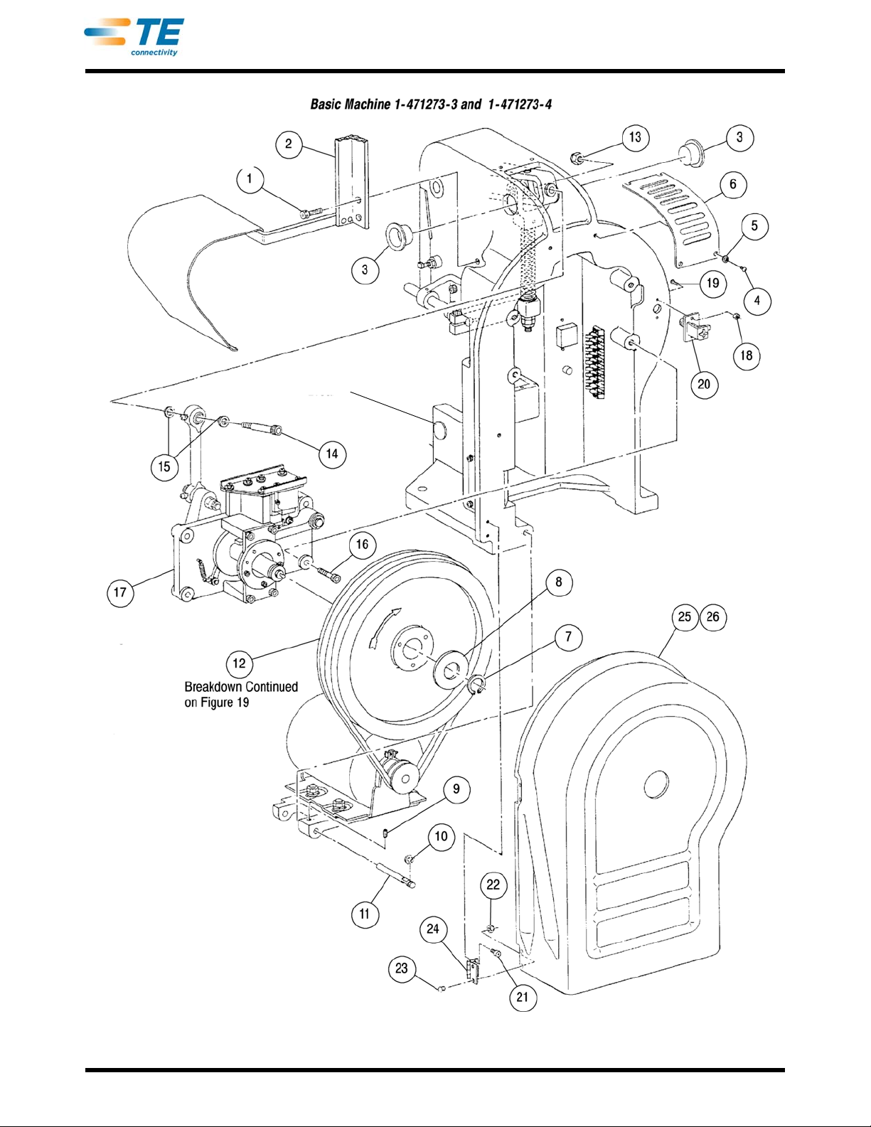
9. PARTS LIST AND EXPLODED VIEW DRAWINGS FOR BASIC MACHINE
Figure 15 through Figure 21 list parts and contain exploded views that cover all items on the basic machine.
Each parts list is itemized numerically in the order of disassembly. Figure 15 shows the basic machine with
references to other figures for subassemblies.
The nomenclature (DESCRIPTION) for subassemblies and detail parts are indented under the next higher
assembly
required for the next higher assembly.
Part numbers marked with a ( • ) indicate wear parts that ar
responsibility to stock and replace. Refer to the INFORMATION REQUIRED WHEN CONTACTING THE
TOOLING ASSISTANCE CENTER in the front of this manual.
on which they are used. The QUANTITY PER ASSEMBLY column indicates the number of items
e recommended spares and are the customer's
For ordering purposes, please use both the exploded view drawings and the drawings shipped with the machine.
Rev Z
21 of 61
Page 22

409-5128
ITEM PART NUMBER DESCRIPTION QTY
- - - 1-471273-3 MACHINE ASSEMBLY, Basic Machine (115V 60Hz) - - -
- - - 1-471273-4 MACHINE ASSEMBLY, Basic Machine (230V 50Hz) - - -
1 3-21001-3 SCREW, Skt Hd Cap, 3/8-16 X .750 in. L 2
2 694925-1 BRACKET ASSEMBLY, Vertical Reel (See Figure 18 for Components) 1
3 26148-6 PLUG, Hole 2
4 2-21002-5 SCREW, Btn Hd Skt Cap, 10-32 X .250 in. L 4
5 21899-2 WASHER, Flat, No. 10 2
6 473392 COVER, Top Access Hole 1
7 3-21048-3 RING, Retaining 1
8 373069 WASHER 1
9 21009-2 SETSCREW, Slflkg Skt, 1/4-20 X .250 in. L 1
10 1-21048-3 RING, Retaining 1
11 373555-1 PIN, Motor Support 1
12 - - - MOTOR-FLYWHEEL COMPONENTS (See Figure 19 for Components) 1
13 21022-6 NUT, Slflkg Hex, 3/8-16 1
14 3-21004-4 SCREW, Skt Hd Shldr, .500 Dia X 1.250 in. L Shldr X 3/8-16.625 in. L Thd 1
15 373482 WASHER, Special 2
16 3-21001-7 SCREW, Skt Hd Cap, 3/8-16 X 1.500 in. L 4
17 685169-6
18 21021-4 NUT, Slflkg Hex, 10-32 2
19 3-21002-0 SCREW, Btn Hd Cap, 10-32 X .875 in. L 2
20 1655230-1 FASTENER, Pawl Adjusting 1
21 2-21000-6 SCREW, Skt Hd Cap, 8-32 X .375 in. L 4
22 25098-4 NUT, Slflkg Hex, 8-32 4
23 2-21002-2 SCREW, Btn Hd Cap, 8-32 X .500 in. L 4
24 373425 HINGE, Butt Offset 2
25 852312-1 GUARD, Flywheel 1
26 19942-1 TRIM, Edge, 1219 mm [48 in.] 1
TRANSMISSION ASSEMBLY (Replacement without Solenoid)
(See Figure 20 for Detail Parts)
1
Rev Z
Figure 15 (Cont’d)
22 of 61
Page 23
Breakdown Continued on
Figure 20
Breakdown Continued on
Figure 16
See Figure 18
for Components
409-5128
Rev Z
Figure 15 (End)
23 of 61
Page 24

409-5128
ITEM PART NUMBER DESCRIPTION QTY
- - - 1-471273-3 MACHINE ASSEMBLY, Basic Machine (115V 60Hz) - - -
- - - 1-471273-4 MACHINE ASSEMBLY, Basic Machine (230V 50Hz) - - -
1 3-21001-7 SCREW, Skt Hd Cap, 3/8-16 X 1.500 in. L 2
2 371178 WASHER, Special 2
3 223141-3 PLUG, Protective 1
4 3-21001-6 SCREW, Skt Hd Cap, 3/8-16 X 1.250 in. L 4
5 465004-1 PLATE, Ram Retaining 1
6 373543 PIN, Toggle Link 1
7 1-21007-5 SETSCREW, Skt Hd, 5/16-18 X .250 in. L 1
8 370720 COLLAR, Adjusting Screw 1
9 370719 SCREW, Adjustment 1
10 370718 BLOCK, Adjustment 1
11 3-21002-4 SCREW, Btn Hd Cap, 1/4-2 X 0.625 in. L 1
12 21899-3 WASHER, Flat, 1/4 in. 1
13 455740-1 BRACKET, Guard 1
14 2-21002-5 SCREW, Btn Hd Cap, 10-32 X .250 in. L 2
15 473391 COVER, Side Access 1
16 21001-6 SCREW, Skt Hd Cap, 1/4-20 X 1.000 in. L 6
17 1-21007-0 SETSCREW, Slflkg Skt, 1/4-2 X 1.000 in. L 1
18 23142-1 FITTING, Straight Lubrication 1
19 373535- PIN, Toggle Arm 1
20 - - -
21 23201-1 FITTING, 90° Lubrication 1
22 21077-5 SETSCREW, Sq Hd, 1/4-20 X 1.000 in. L 1
23 1-22202-4 NUT, Hex 1/4-20 1
TOGGLE LEVER-FEED ACTUATING COMPONENTS (See Figure
Breakdown)
21 for
1
Rev Z
Figure 16 (Cont’d)
24 of 61
Page 25
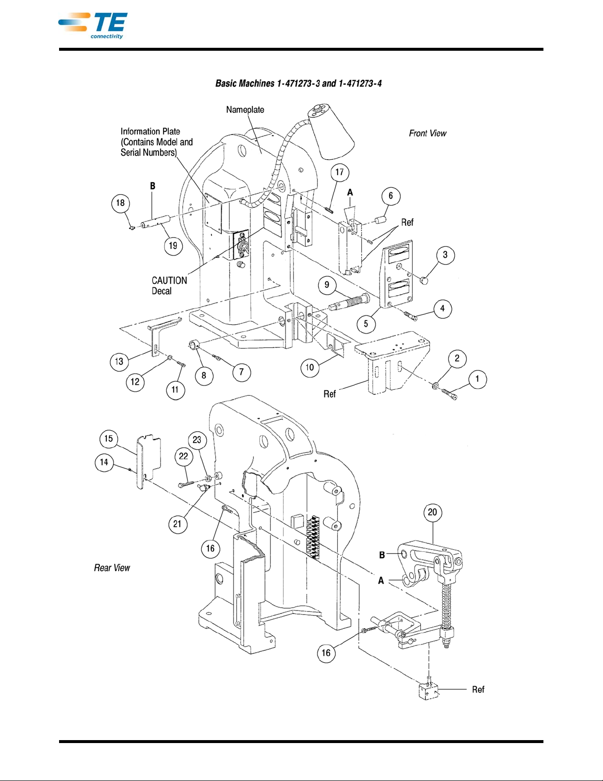
See Figure 21 for
Components
409-5128
Rev Z
Figure 16 (End)
25 of 61
Page 26

409-5128
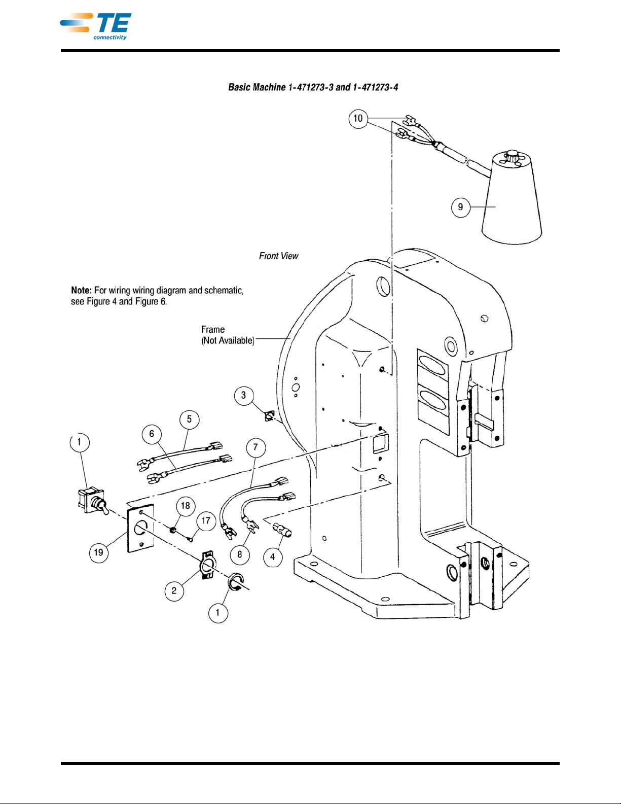
ITEM PART NUMBER DESCRIPTION QTY
- - - 1-471273-3 MACHINE ASSEMBLY, Basic Model “K" Machine (
- - - 1-471273-4 MACHINE ASSEMBLY, Basic Model “K" Machine (
1 20870-2 SWITCH, Toggle 1
2 24195-1 PLATE, Switch 1
3 23403-1 NUT, Speed 1
4
5 691400-7 WIRE, Black, Terminated 1
6 691409-4 WIRE, White, Terminated 1
7 691400-8 WIRE, Black, Terminated 1
8 691409-5 WIRE, White, Terminated 1
9 23430-3 • LIGHT, Work 1
10 640905-1 TERMINAL, FASTON* .250 Series, Blue 2
11 2-21002-5 SCREW, Btn Hd Skt Cap, 10-3 X 2.250 in. L 2
12
13 3-21000-1 SCREW, Skt Hd Cap, 8-32 X 1.00 in. L 2
14 854586-1 BARRIER STRIP, Modified 1
15 21060-7 SCREW, Self-Tapping, 4-24 X .250 in. L 2
16 453866-1 GUARD, Foot Switch 1
23709-1 LIGHT, Indicator (115 Vac) 1
23709-2 LIGHT, Indicator (230 Vac) 1
453586-3 BOX ASSEMBLY, Trip Control (115 Vac) 1
453586-5 BOX ASSEMBLY, Trip Control (230 Vac) 1
115V 60Hz) - - -
230V 50Hz) - - -
Figure 17 (Cont’d)
Rev Z
26 of 61
Page 27

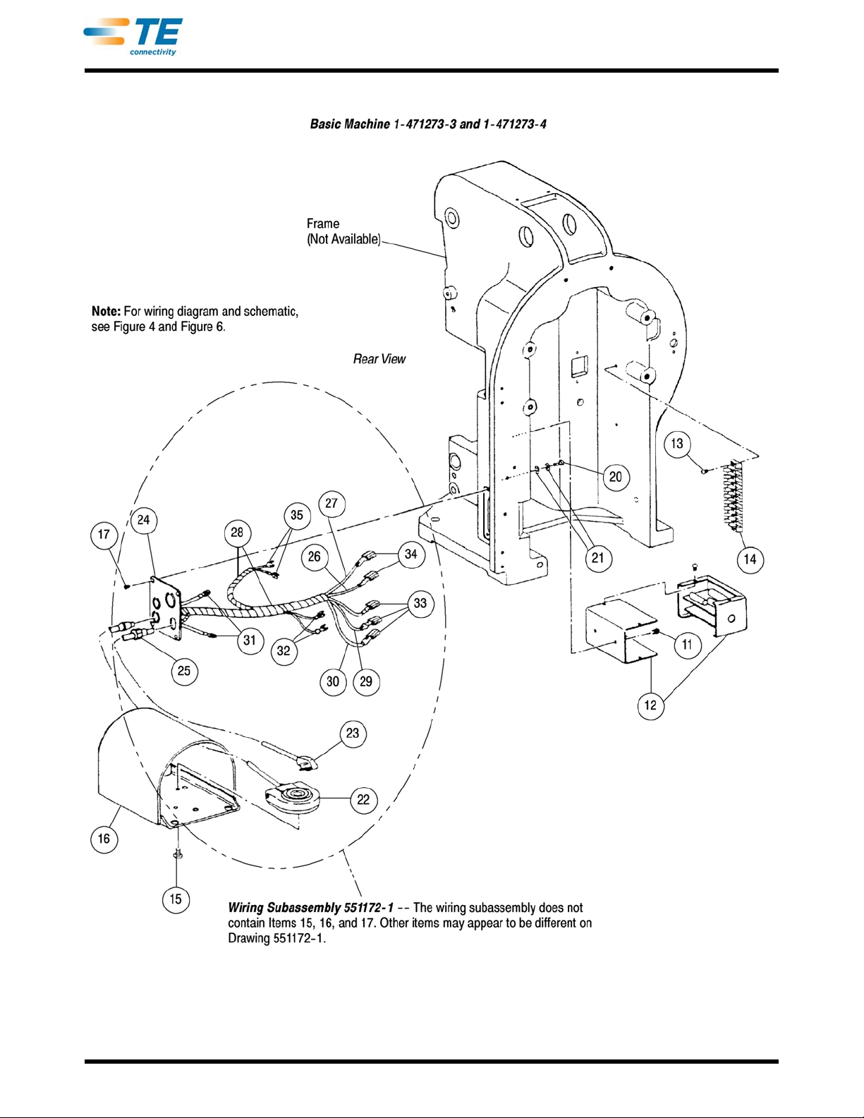
ITEM PART NUMBER DESCRIPTION QTY
17 1-21002-6 SCREW, Btn Hd Cap, 6-32 X .250 in. L 6
18 1-21899-3 WASHER, Flat, No. 8 2
19 373306-2 PLATE, Switch Adapter 1
20 5-21063-5 SCREW, Brass Rnd Hd, 10-32 X .375 in. L 1
21 21075-5 WASHER, Int Tooth Lock, No. 10 2
- - 551172-1 • WIRING SUBASSEMBLY 1
22 551170-1 • SWITCH, Foot (Terminated) 1
23 467516-1 • PLUG, Line 1
24 810551-1 PLATE, Harness Adapter 1
25 1-22242-9 BUSHING, Strain Relief 1
26 1-23497-0 WIRE, Black, No. 16, 483 mm [19 in.] 1
27 23497-9 WIRE, White, No. 16, 483 mm [19 in.] 1
28 500024-1 WRAP, Cable, SPIRAP*, 1/4 in., 610 mm [24 in.] 1
29 23125-4 TAPE, Blue, 51 mm [2 in.] 1
30 23125-6 TAPE, Yellow, 51 mm [2 in.] 1
31 2-320552-1 TERMINAL, PIDG* Ring Tongue, No. 10 2
32 60279-2 TERMINAL, FASTON Piggyback, .250 Series 2
33 2-50182-2 TERMINAL, FASTON Ultra-Fast, .187 Series, Red 3
34 3-350816-2 TERMINAL, FASTON Ultra-Fast, .187 Series, Blue 2
35 3-520133-2 TERMINAL, FASTON Ultra-Fast Flag Receptacle, .250 Series 2
• Recommended Spare Part
409-5128
Figure 17 (Cont’d)
Rev Z
27 of 61
Page 28
409-5128
Rev Z
Figure 17 (Cont’d)
28 of 61
Page 29
409-5128
Rev Z
Figure 17 (End)
29 of 61
Page 30
409-5128
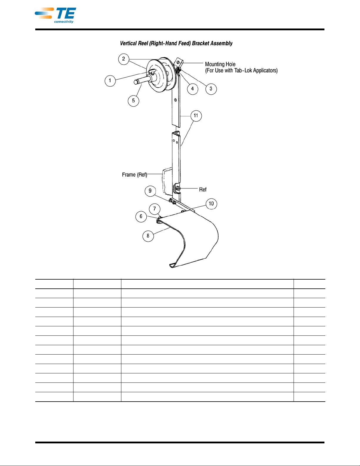
ITEM PART NUMBER DESCRIPTION QTY
- - - 694925-1 • BRACKET ASSEMBLY Vertical Reel (Right-Hand F
1 2-22789-6 SCREW, Thumb Wing, 1/4-20 X .500 in. L 2
2 465520-1 FLANGE, Reel 2
3 3-21001-3 SCREW, Skt Hd Cap, 3/8-16. X 750 in. L 1
4 21024-8 WASHER, Spring Lock, 3/8 in. 1
5 465586-2 SHAFT, Reel 1
6 2-21000-5 SCREW, Skt Hd Cap, 8-32. X 500 in. L 2
7 1-21899-3 WASHER, Flat, No. 8 2
8 470268-1 GUIDE, Stock 1
9 2-21000-6 SCREW, Skt Hd Cap, 8-32 X .375 in. L 2
10 694927-1 BRACKET, Stock Guide 1
11 694926-1 SUPPORT, Vertical Reel 1
• Recommended Spare Parts
Figure 18
eed) - - -
Rev Z
30 of 61
Page 31
409-5128
ITEM PART NUMBER DESCRIPTION QTY
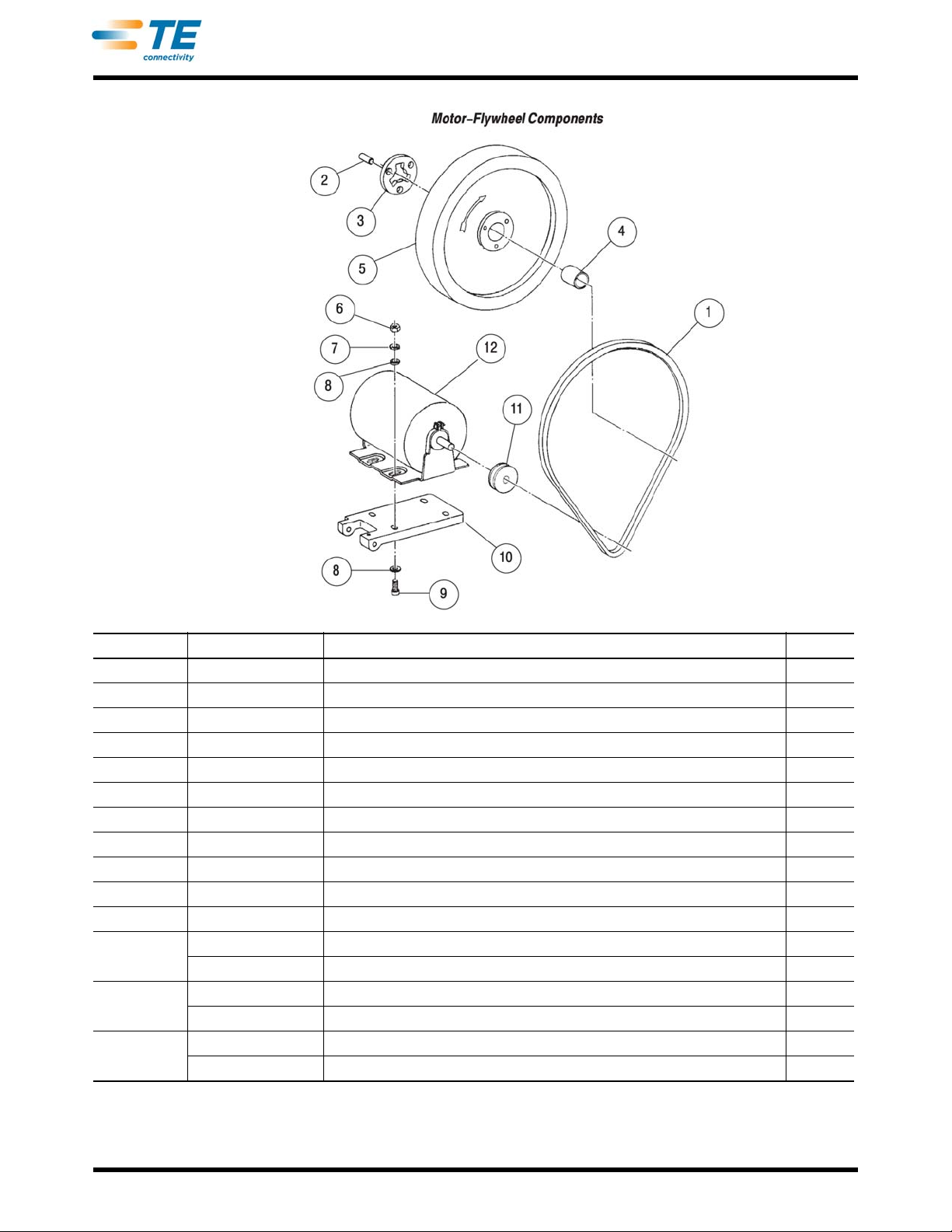
- - - - - - MOTOR-FLYWHEEL COMPONENTS - - -
1 23139-1 • V-BELT 1
- - - 5570646-1 FLYWHEEL ASSEMBLY 1
2 23143-1 PIN, Dowel, .125 Dia X .500 in. L 3
3 375021 PLATE, Drive 1
4 469766-1 BUSHING, Flywheel, Replacement 1
5 - - - FLYWHEEL (Not Available Separately; Order Flywheel Assembly) 1
6 21019-2 NUT, Hex, 5/16 in. 4
7 21024-7 WASHER, Spring Lock, 5/16 in. 4
8 21899-4 WASHER, Flat, 4/16 in. 8
9 2-21001-0 SCREW, Skt Hd Cap, 5/16-18 X 1.000 in. L 4
10
11
12
• Recommended Spare Part
570233 MOUNT, Motor (for the 1-471273-3 Machine) 1
570233-1 MOUNT, Motor (for the 1-471273-4 Machine) 1
23876-1 PULLEY, V-Belt, 2.0 in. Outside Diameter (for the 1-471273-3 Machine) 1
23876-2 PULLEY, V-Belt, 2.25 in. Outside Diameter (for the 1-471273-4 Machine) 1
843997-2 MOTOR, AC , 1/4 Hp, 115 Vac 60Hz, (for the 1-471273-3 Machine) 1
23525-2 MOTOR, AC, 1/4 Hp, 230 Vac, 50Hz, (for the 1-471273-4 Machine) 1
Figure 19
Rev Z
31 of 61
Page 32

409-5128
ITEM PART NUMBER DESCRIPTION QTY
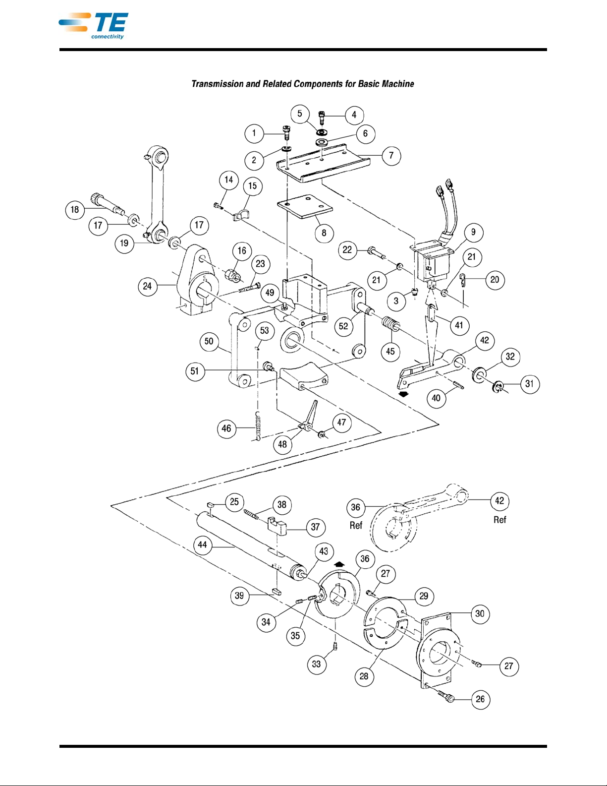
- - - - - - TRANSMISSION COMPONENTS, Basic Machine - - -
1 22140-3 SCREW, Skt Hd Cap, 1/4-20 X .625 in. L 3
2 21899-3 WASHER, Flat, 1/4 in. 3
3 21021-4 NUT, Slflkg Hex, 10-32 4
4 3-21000-7 SCREW, Skt Hd Cap, 10-32.75 in. L 4
5 21899-2 WASHER, Flat, No. 10 4
6 19342-3 GROMMET 4
7 551260-1 ‡ MOUNT, Solenoid 1
8 809891-1 SPACER 1
9 551406-7 • SOLENOID, (Terminated) Used with 115 Vac and 230 Vac Machine 1
14 22168-8 SCREW, Self-Tapping, 6-32. X 250 in. L 1
15 24077-1 CLIP, Cable 1
16 21022-6 NUT, Slflkg Hex, 3/8-16 1
17 373482 WASHER, Special 2
18 3-21004-6 SCREW, Skt Hd Shldr, 1/2 Dia X 1.750 in. L Shldr 3/8-16 X .625 in. L Thd 1
19 457909-1 LINK, Spherical Bearing 1
- - - 685169-9 TRANSMISSION ASSEMBLY 1
20 23138-2 PIN, Cowling 1
21 21023-7 WASHER, Flat,, No. 10 2
22 811939-2 PIN, Clevis 1
23 5-21909-5 SCREW, Skt Hd Cap, 7/16-14 X 1.500 in. L 1
24 465620-2
ARM, Eccentric
25 1-22548-4 KEY, Woodruff 1
26 21001-4 SCREW, Skt Hd Cap, 1/4-20.750 in. L 4
27 2-21000-7 SCREW, Skt Hd Cap, 8-32 X .500 in. L 6
28 551266-1 RETAINER, Dog 1
29 811924-1 WEDGE, Dog, Return 1
30 811921-1 SUPPORT, Dog Retainer 1
31 23716-8 RING, Retaining, .500 in. Dia 1
32 551333-1 WASHER, Nylon 1
• Recommended spare part.
‡ To replace the solenoid mount, and solenoid is not shock-mounted,
Items 5, 6, and 8 must be ordered with Item 7.
Figure 20 (Cont’d)
1
Rev Z
32 of 61
Page 33

409-5128
ITEM PART NUMBER DESCRIPTION QTY
33 21009-2 SETSCREW, Slflkg Skt, 1/4-20 X .250 in. L 1
34 21014-5 SCREW, Lkg Type, 1/4-20 X .125 in. L 1
35 21009-3 SETSCREW, Slflkg Skt, 1/4-20 X .312 in. L 1
36 811925-1 COLLAR, Stop 1
37 811938-1 DOG, Clutch 1
38 372687 SPRING, Compression 1
39 551353-1 KEY, Square 1
40 21029-9 PIN, Slotted Spring, 3/16 Dia X 1.000 in. L 1
41 565387-1 LINK, Solenoid 1
42 465622-1 BAR, Stop 1
43 22792-1 FITTING, Straight Lubrication 1
44 551336-1 SHAFT, Main 1
45 5-21085-0 O-RING 12
46 565339-1 SPRING, Extension 1
47 1-21986-5 RING, Ext “E” Retaining, .312 in. Dia 1
48 811926-1 LATCH, Backup 1
49 23142-1 FITTING, Straight Lubrication 1
50 565149-1 MOUNT, Crankshaft (with Bushing and Pins Installed) 1
51 551335-1 PIN, Pivot, .312 Dia X 1.000 in. L 1
52 551335-2 PIN, Pivot, .500 Dia X 2.250 in. L 1
53 2-22183-7 PIN, Grooved, .165 Dia X .875 in. L 1
Figure 20 (Cont’d)
Rev Z
33 of 61
Page 34
409-5128
Rev Z
Figure 20 (End)
34 of 61
Page 35

409-5128
ITEM PART NUMBER DESCRIPTION QTY
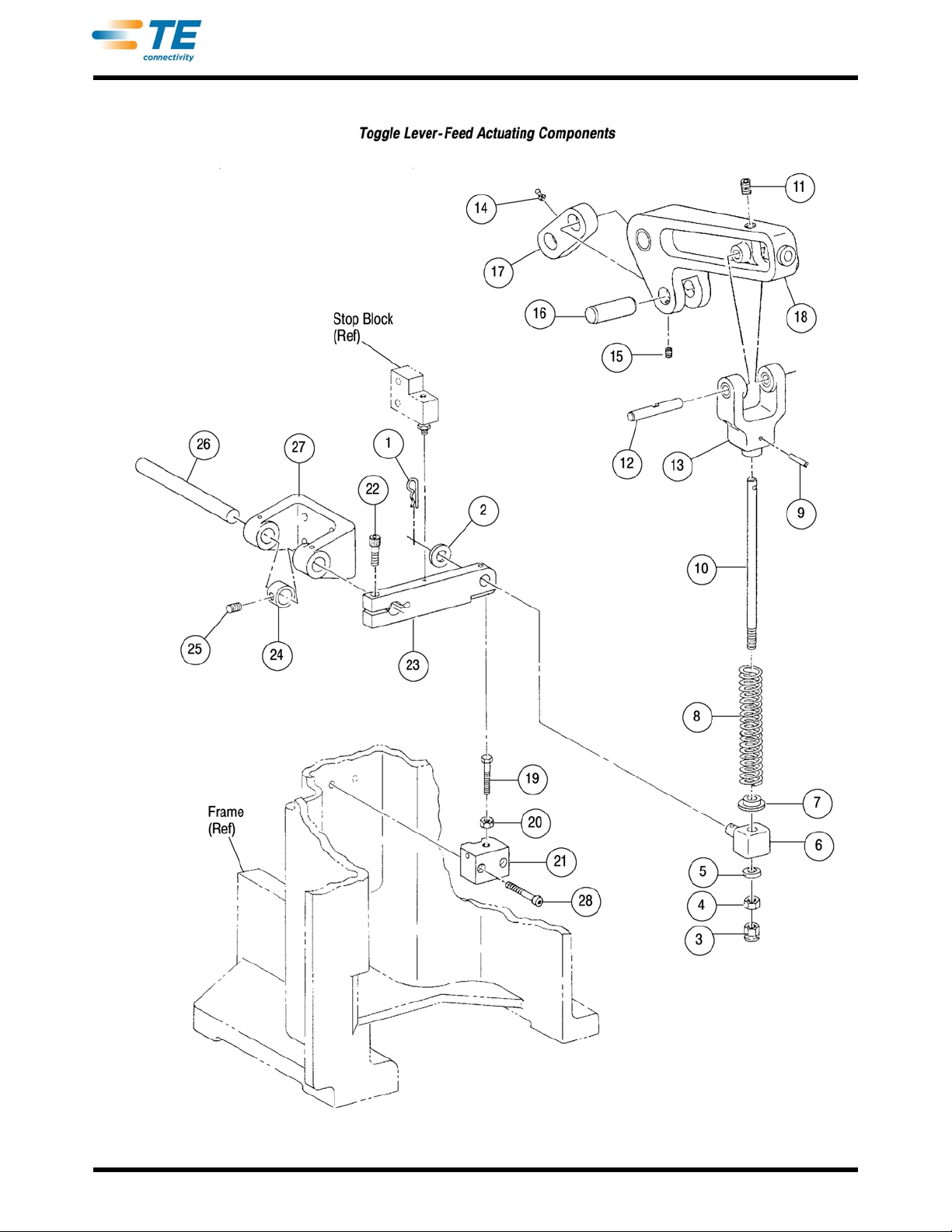
- - - - - - TOGGLE LEVER-FEED ACTUATING COMPONENTS - - -
1 23138-3 PIN, Cowling 1
2 21899-7 WASHER, Flat, 1/2 in. 1
3 1-21021-7 NUT, Slflkg Hex, 3/8-24 1
4 22595-6 NUT, Hex Lk, 3/8-24 1
5 373479 COLLAR, Feed Rod 1
6 375092 BLOCK, Feed Actuating 1
7 373475 RETAINER, Spring 1
8 373476 SPRING, Feed Return 1
9 21029-9 PIN, Slotted Spr, .187 Dia X 1.000 in. L 1
10 373477 ROD, Feed Connecting 1
11 21009-7 SETSCREW, Slflkg Skt, 1/4-20 X .625 in. L 1
12 376190 PIN, Clevis 1
13 373339-1 CLEVIS, Toggle Lever 1
14 23142-1 FITTING, Lubrication 1
15 21009-4 SETSCREW, Slflkg Skt, 1/4-20 X .375 in. L 1
16 373543 PIN, Toggle Link 1
17 373542- LINK, Toggle 1
18 471125 LEVER, Toggle, 11/8 in. Stroke 1
19 452489-1 SCREW, Damper 1
20 21020-3 NUT, Hex Jam, 3/8-16 1
21 452488-3 BLOCK, Damper Mounting 1
22 3-21001-6 SCREW, Skt Hd Cap, 3/8-16 X 1.250 in. L 1
23 373346 ARM, Feed Actuating 1
24 22292-9 COLLAR, Shaft (Supplied with Item 25, Setscrew) 1
25 1-21007-5 SETSCREW, Cup Pt Skt, 5/16-18 X .250 in. L 1
26 373503 SHAFT, Feed Arm Drive 1
27 465006- BRACKET, Feed Actuating 1
28 21001-6 SCREW, Skt Hd 1/4-20 X 1.000 in. L 1
Rev Z
Figure 21 (Cont’d)
35 of 61
Page 36
409-5128
Rev Z
Figure 21 (End)
36 of 61
Page 37

409-5128
DANGER
STOP
10. MACHINE ACCESSORIES
This section pertains to those accessories that when factory installed change the basic machine to one of the
modified machines presented in Section 1 1 . These same accessories are available for field conversions, making
it possible to change a modified machine of one configuration to that of another. The assembly (or assemblies)
required, and the parts that will need to be removed, depend on the intended application and the type of
applicator to be installed. The applicator pa rts list and applicator instructions specify the accessories required for
the use of that particular applicator.
Following is a list of the assemblies availab
necessary instructions for installation and required a djustments. In case s where the require d procedures appear
in the instructions for the applicator, they are not repeated in this manual.
le as accessories, with the paragraph identified that provides the
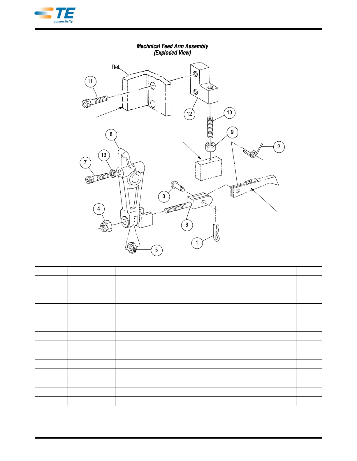
• 10.1.Mechanical Feed Arm Assembly
• 10.2.Air Feed Valve Assembly
• 10.3.Air Feed Assemblies
• 10.4.Air Blast Assemblies
• 10.5.Optional Reel Bracket Assemblies and Associated Parts
10.1. Mechanical Feed Arm Assembly
A. Description
The mechanical feed arm assembly is used with all standard applicators that requir e a mechanical feed of the
terminal strip. The assembly is installed on the front of the feed arm drive shaft, which is a part of the basic
machine. The feed finger (supplied with applicator) is attached to the feed adjusting clevis. The stop block,
supplied with the assembly, is attached to the machine frame with screws in the same location as the vertical
reel bracket assembly.
When the machine is in the rest position (TOP-DEAD-CENTER), the feed
lead terminal on the strip with the applicator tooling. As the machine is cycled an d the ram is on the downward
stroke, the feed finger is fully retracted by the feed mechanism as the ram nears the bottom of the stroke. This
gives a slight overtravel of the feed finger to ensure positive pickup of the terminal strip in the next feed
location. In the upward stroke, the feed mechanism advances the feed finger and terminal str ip.
(Figure 22)
finger is fully extended to align the
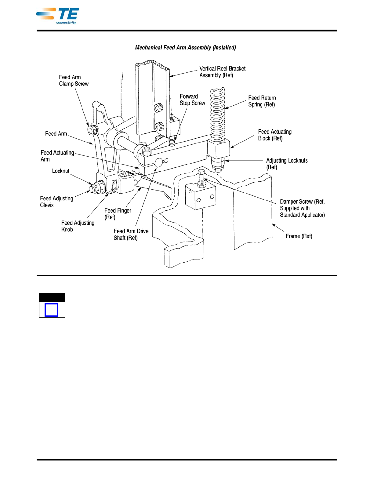
B. Adjustment (Figure 22)
To avoid personal injury, ALWAYS disconnect electrical and air supply before attempting any adjustments.
1. Make certain the machine is at TOP-DEAD-CENTER. If necessary
2. If mechanical feed arm has been removed, in stall it on
screw at this time.
3. Install applicator and feed finger as described in the applicator instructions supplied with the applicator.
4. Loosen locknut on feed adjusting clevis, and turn feed adjusting
on clevis.
5. Load terminal strip into applicator (in accord with the
terminal over anvil.
6. Position feed finger against feed point
necessary, loosen clamp screw). Maintain this position and tighten clamp screw to secure arm on shaft.
7. Hand-cycle machine until feed finger drips in back of ne
rear stop screw and damper screw to allow more travel of feed arm. A slight overtravel of feed finger is
recommended to ensure proper feeding of terminal strip.
8. With slight overtravel obtained, turn rear stop scre
in terminal strip for lead terminal by rotating arm on drive shaft (if
feed arm drive shaft. Do not tighten feed arm clamp
instructions for the applicator), and center the lead
xt feed point in terminal strip. If necessary, loosen
w out against feed arm and secure it with locknut.
, hand-cycle it to obtain this condition.
knob so it is near the middle of travel range
Rev Z
37 of 61
Page 38
409-5128
NOTE
i
Figure 22
It should be noted that the machine is not at BOTTOM-DEAD-CENTER nor is ram at bottom of stroke. This is normal and
will be compensated for by the feed return spring.
9. Adjust damper screw until it JUST
adjustment must be correct; otherwise, feed arm will not feed properly.
10. Check to see that approximately three threads ar
connecting rod when locknuts are tight.
11. Continue to hand-cycle until machine returns to TOP-DEAD-CENTER.
12. Cycle machine under power to check for proper adjustment of feed arm. If necessary, make further
ad
justment with feed adjusting knob, and then lock feed adjusting clevis by tightening locknut. If necessary,
adjust feed finger tension as described in the applicable applicator instructions.
TOUCHES the feed actuating arm, then tighten locknut to secure it. This
e exposed below the adjusting locknuts on feed
C. Replacement (Figure 23)
Because of the simplicity in design, there are no special procedures required for replacement of parts in the
mechanical feed arm assembly.
Rev Z
38 of 61
Page 39
Feed Finger (Ref, Supplied
)with the Standard Applicator
Feed Actuating Arm
Vertical Reel Bracket
Assembly (Ref)
409-5128
ITEM PART NUMBER DESCRIPTION QTY
- - - 692140-2 • ARM ASSEMBLY, Mechanical Feed 1
1 23138-1 PIN, Cowling 1
2 374112 SPRING, Feed Tension 1
3 374651 PIN, Feed Clevis 1
4 1-21021-7 NUT, Slflkg Hex, 3/8-24 1
5 374114 KNOB, Feed Adjusting 1
6 375020 CLEVIS, Feed Adjusting 1
7 3-21001-8 SCREW, Skt Hd Cap, 3/8-16 X 1.750 in. L 1
8 471308-1 ARM, Feed 1
9 21019-8 NUT, Hex Mach, 5/16-24 1
10 7-21011-9 SETSCREW, Fl Pt Skt, 5/16-24 X 2.00 in. L 1
11 3-21001-6 SCREW, Skt Hd Cap, 3/8-16 X 1.250 in. L 2
12 240033-2 BLOCK, Stop 1
13 1-21055-0 WASHER, Flat, 3/8 in. 1
• Recommended Spare Part
Figure 23
Rev Z
39 of 61
Page 40
409-5128
DANGER
STOP
NOTE
i
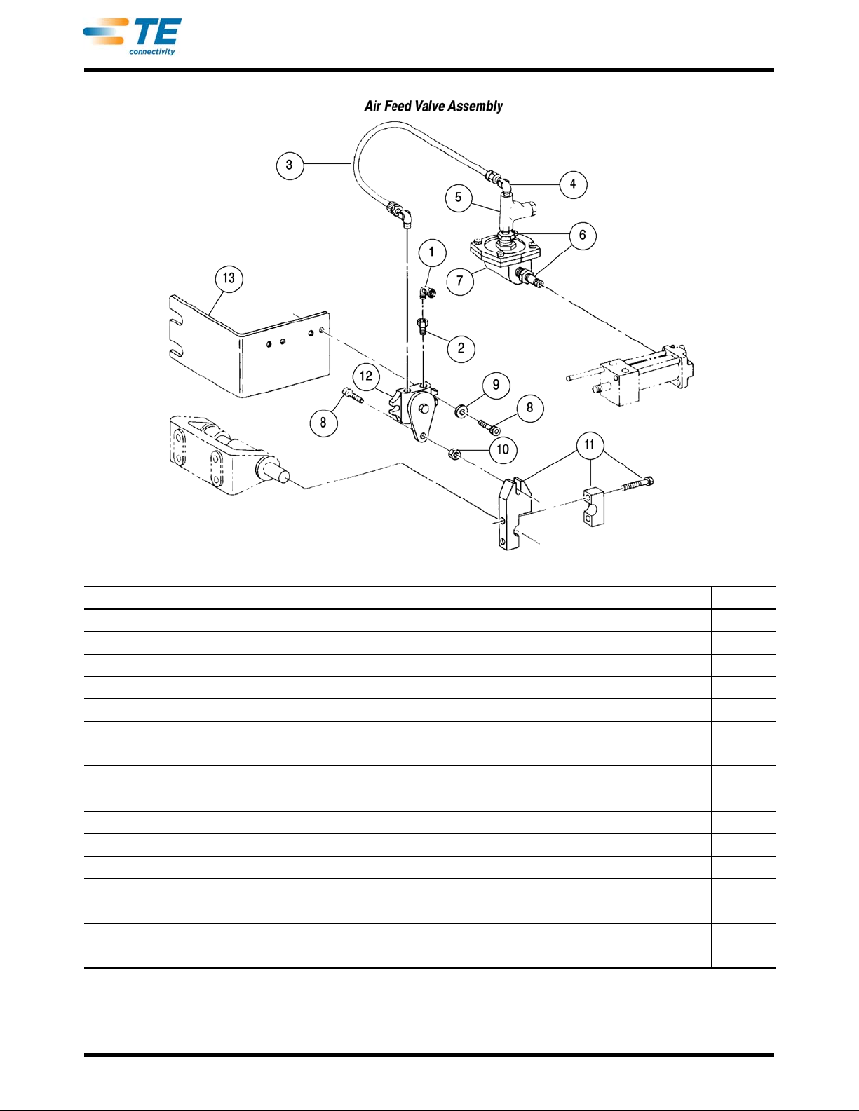
10.2. Air Feed Valve Assembly (Figure 24) A. Description
The air feed valve assembly is used to supply air pressure to all types of applicator air feed arrangements.
The assembly consists of a valve bracket, on-off va lve, operating arm, flow control valve, quick-exhaust valve,
and tubing with fittings.
The operating arm is installed on the fro nt end of the feed a
"open" when the machine is at TOP-DEAD-CENTER. This supplies pressure to the air feed cylinder. On the
downward stroke, the on-off valve is actuated "closed" to stop pressurization of the cylinder and allow trapped
air within the cylinder to exhaust to atmosphere through the quick- exhaust valve. On th e upward stro ke of the
ram, the on-off valve is actuated "open" aga in to pressure the cylinder. The flow control valve is adjusted to
control the speed of the cylinder.
rm drive shaft to operate the on-o f f valve, wh ich is
B. Adjustments
To avoid personal injury, ALWAYS disconnect electrical and air supply before attempting any adjustments.
Two adjustments can be made to the air feed valve assemb
mechanical feed arm drive shaft; the other is adjusting the flow control valve.
Adjust the operating arm as follows:
1. Make sure machine is at TOP-DEAD-CENTER. If nec
2. Disconnect air line to f
3. Apply air pressure to the on-off valve. If the valve is n
rotate arm as necessary to open valve fully, then tighten screws.
If the machine has a damper screw and/or forward stop screw (see Figure 22), screws MUST be backed off so that they
are not active.
4. Hand-cycle machine through one cycle
Connect air line that was disconnected in Step 2. Disconnect air supply.
Adjust the flow control valve as follows:
To adjust the flow control valve, an applicator must be in
With the air supply connected, hand-cycle the machine through several co mplete cycles. During cycling,
check the speed of the feed stroke-keeping in mind that the speed of the feed stroke is basically the same
whether hand-cycled or operated under power. The feed stroke should be slow enough to prevent
overfeeding or deformation of terminals. Note, however, that a feed stroke that is too slow will hinder
production by the operator.
1. Loosen locknut on flow control valve.
2. To decrease speed, turn adjustment screw clockwise; to increase speed, turn adjustment screw
counterc
3. After adjustment, tighten locknut, then disconnect air supply.
lockwise.
low control valve.
of operation to be sure valve is closing at bottom of ram stroke.
ly. One is adjusting the operating arm on the
essary, hand-cycle it to obtain the condition.
ot fully open, loosen two screws in operating arm and
stalled in the machine and loaded with terminal strip.
C. Replacement
There are no special procedures required for re placement of part s in the air feed valve assembly. Refer to the
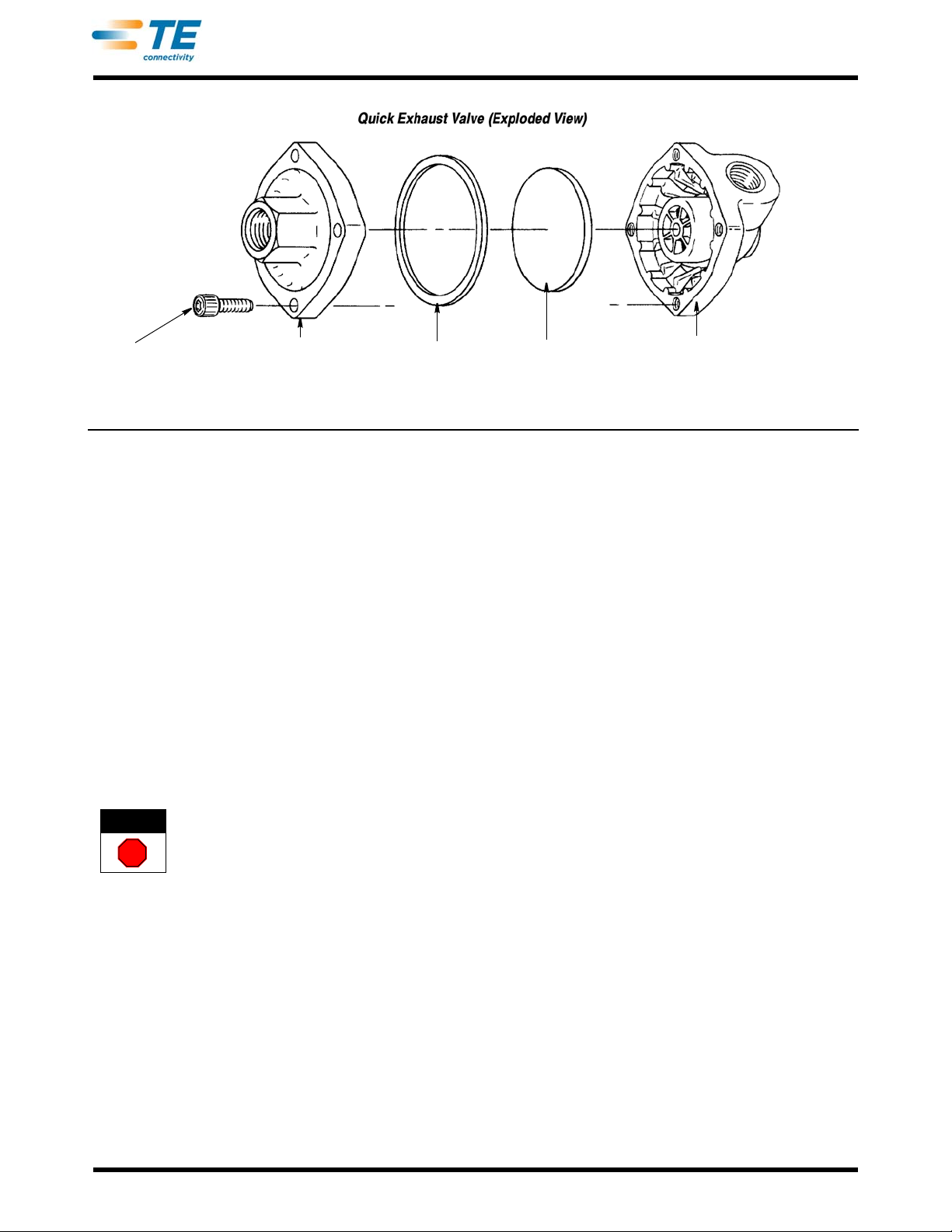
exploded view and parts list for detail parts. If it is necessary to repair the quick-exhaust valve (Item 7), install
Valve Repair Kit 22989-1 (diaphragm and gasket) as shown in Figure 25.
Rev Z
40 of 61
Page 41
409-5128
ITEM PART NUMBER DESCRIPTION QTY
- - - 692655-1 • VALVE ASSEMBLY, Air Feed - - -
1 22306-2 ELBOW, Street, 1/4 x 1/4 in. NPT 1
2 22312-4 ADAPTER, Hex, 1/8 X 1/4 in. NPT 1
3 27319-4 TUBING, Plastic, 1/4 in. Outside Diameter, 381 mm [15 in.] 1
4 980285-2 ELBOW, Male, 1/8 in. NPT X 1/4 in. Outside Diameter Tube 2
5 23054-1 VALVE, Flow Control 1
6 22304-1 NIPPLE, Hex, 1/83/8 in. NPT 2
7 22374-7 VALVE, Quick Exhaust 1
- - - 22989-1 KIT, Valve Repair (Includes Diaphragm and Gasket for Schrader Valve 3340) 1
- - - 682469-1 KIT, Valve Repair (Includes Diaphragm and O-Ring for Deltrol Valve EN 375) 1
8 3-21000-5 SCREW, Skt Hd Cap, 10-32 X .500 in. L 3
9 21899-2 WASHER, Flat, No. 10 2
10 21018-7 NUT, Hex, 10-32 1
11 378393 ARM, Operating 1
12 23018-1 VALV E, On -Off 1
13 452899-2 BRACKET, Air Valve 1
• Recommended spare Part
Figure 24
Rev Z
41 of 61
Page 42
Cap Screw
Inlet Body
Gasket
Diaphragm
Exhaust Body
Note: Schrader valve shown, Deltrol valve is similar.
10.3. Air Feed Assemblies
DANGER
STOP
409-5128
Figure 25
A. Description
(Figure 26)
There are three different types of air fe ed assemblies available, each with a specific purpose, but similar in
design and operation. Air pressure is supplied to each assembly by an air feed valve assembly (Paragraph
10.2) connected to either the extension port or retraction port of the cylinder when the machine is in the rest
position. On the downward stroke of the ram, the air supply is shut "off" and the piston is moved in the
opposite direction by spring pressure; then, on the upward stroke of the ram, the cylinder is again pressuri zed
and the piston returns to its original position. The air feed assemblies are all prefeed, meaning that the
terminal is positioned over the anvil when the machine is at TOP-DEAD-CENTER.
The cylinder is mounted on a feed adjusting bracket, which pe
rmits horizontal adjustment of the cylinder by
the feed adjusting screw, and angle adjustment by means of the swivel screw. The length of the cylinder
stroke-whether 25.4 or 50.8 mm [1 or 2 in.]-is adjusted to the desir ed length by means of the piston positioner .
This desired length is equal to one feed length of the terminal strip to be fed.
The air feed assemblies are supplied with the applicator, but are included in this manual to cover the
a
djustments and the replacement of detail parts.
B. Adjustments (Figure 26)
To avoid personal injury, ALWAYS disconnect electrical and air supply before attempting any adjustments.
1. Make certain the machine is at TOP-DEAD-CENTER. If necessary
2. Install applicator and feed finger as described in the ap
plicator instructions supplied with the applicator . The
air feed valve assembly must be installed and adjusted as described in Paragraph 10.2.
, hand-cycle it to obtain this condition.
3. Load terminal strip into applicator in accord with applicator instructions.
4. Check angle of feed adjusting bracket. It should be position
straight line. If necessary, loosen the swivel screw, and raise or lower the cylinder to obtain the correct
position. Tighten the swivel screw.
5. If applicable, check mounting screws in feed swivel bracke
not centered, loosen screws and adjust bracket position, and then tighten screws.
6. Check that lead terminal is centered over anvil. If p
Rev Z
ed so the cylinder and feed finger are in a
t. They should be centered in the slotted holes. If
refeed assembly, leave air supply disconnected.
42 of 61
Page 43
Base Mount (Ref)
Feed Swivel Bracket
Feed Adjusting Bracket
Swivel Screw
Feed
Adjusting
Screw
Lockscrew
Piston
Positioner
Vertical Reel Bracket
Assembly (Ref)
Valve
Bracket
Air Supply Inlet
ON-OFF
Valve
Flow Control Valve
Operating Arm
Guide Rod
Feed Bracket (Ref)
Flow Adjustment
Screw
Feed
Adjusting
Block
Typical Air
Cylinder
409-5128
Rev Z
Figure 26
43 of 61
Page 44

409-5128
7. Check that feed finger is against feed point in terminal strip for lead terminal. If not, loosen lockscrew
securing feed adjusting block, and turn feed adjusting screw, as required, until feed finger is against feed point
and lead terminal remains centered over anvil. Tighten lockscrew to secure adjustment.
8. Check position of piston positioner. It must be one feed length (as specified on the applicator parts list) plug
enough overtravel on the feed finger retract stroke to drop into the next feed point. If not, loosen two screws
securing it to piston rod and slide in the required direction to obtai n this dimension, and tighten screws to
secure it.
9. Connect air supply. This will retract feed finger to pick up next feed point in terminal strip.
10. Hand-cycle machine to extend-feed finger fully, and then check that terminal is centered on anvil. If not,
adjust feed adjusting block as described in Step 7.
11. Continue to hand-cycle machine to return it to the rest position. If necessary, adjust feed finger tension as
described in the applicable applicator instructions.
12. Cycle machine under power several times to check for proper adjustment. If necessary, repeat preceding
steps as required.
13. With adjustment completed, disconnect air supply.
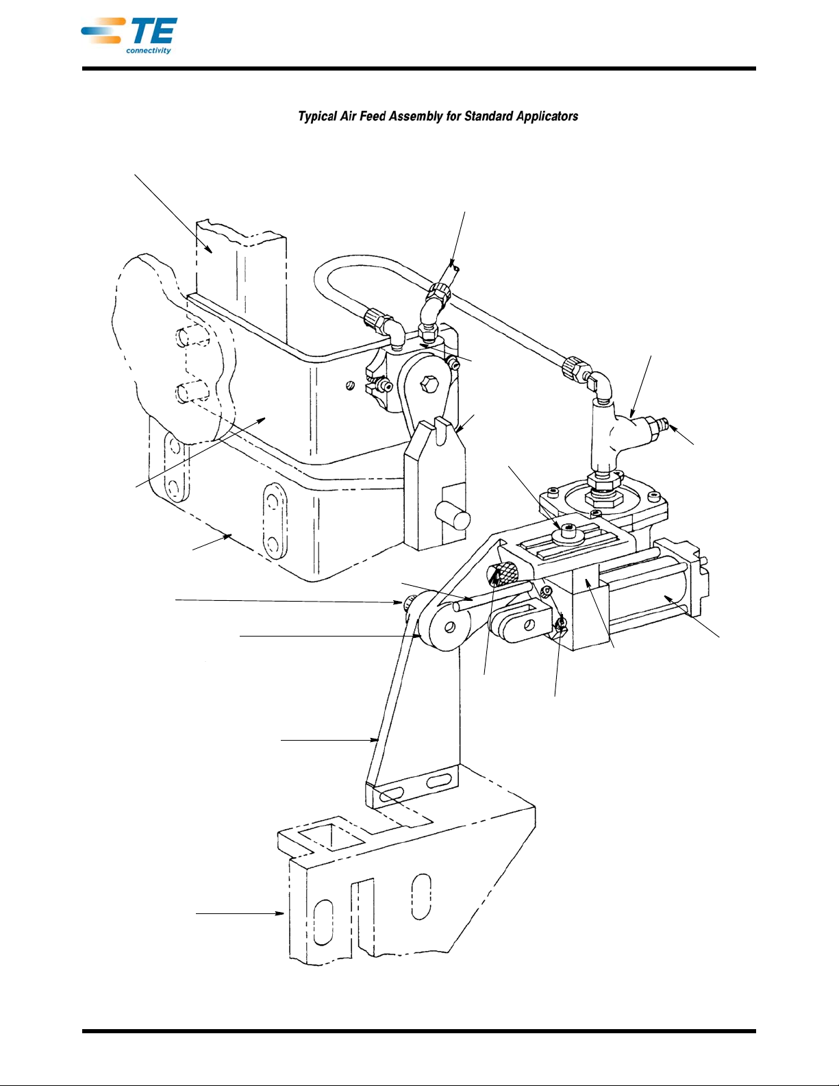
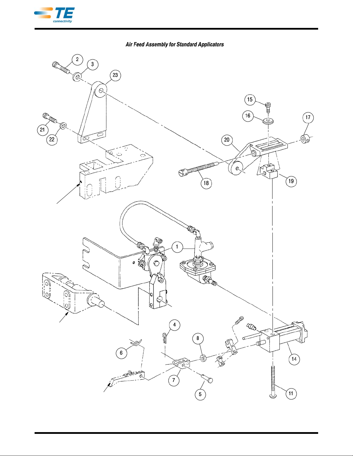
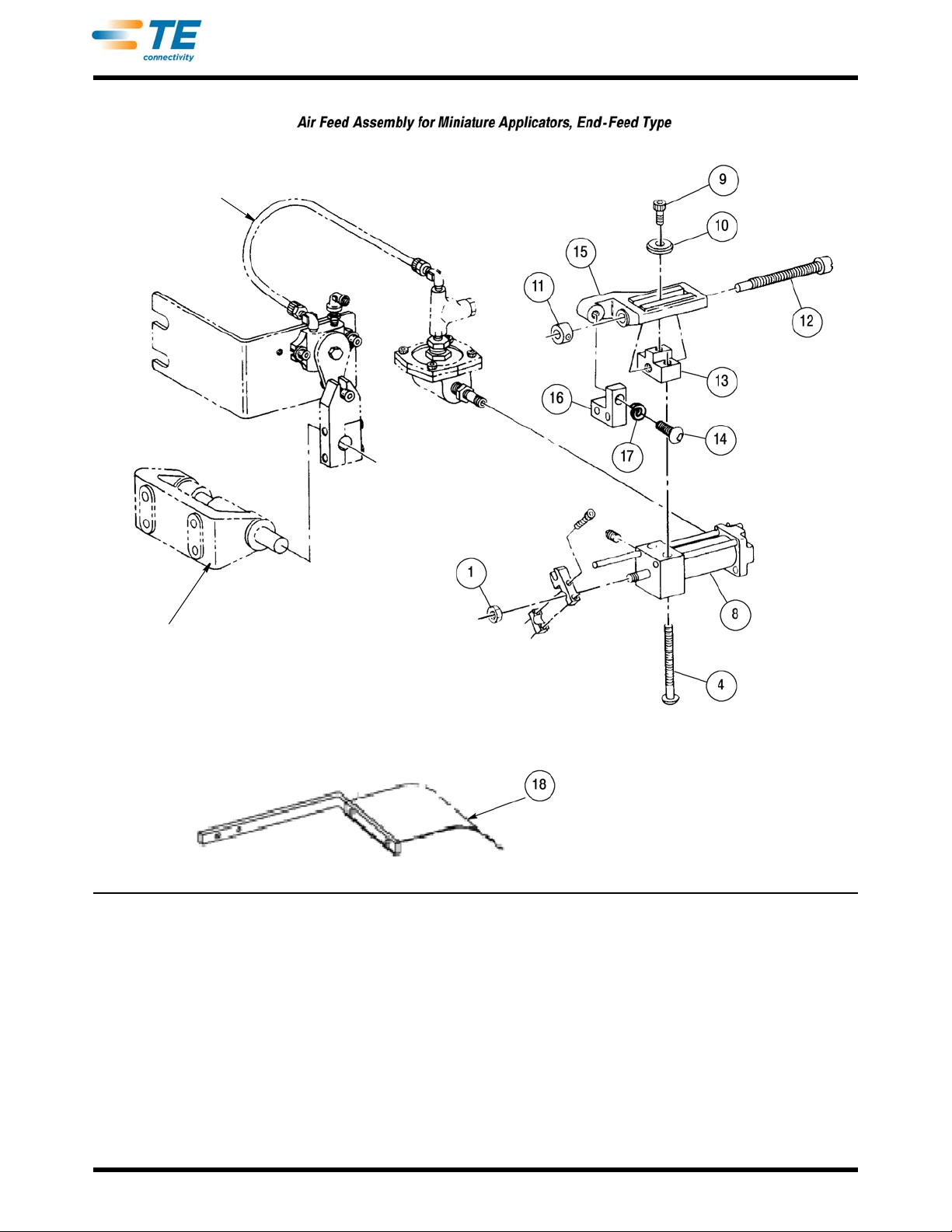
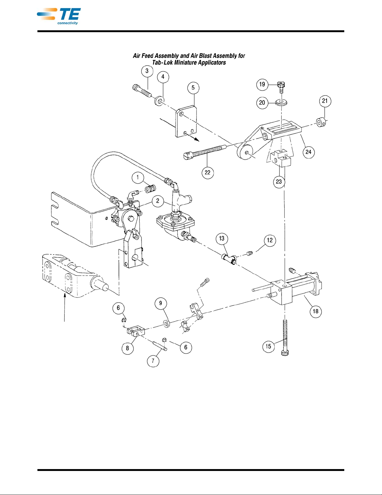
C. Replacement (Figure 27 through Figure 29)
There are no special procedures required for replacement of parts in the air feed assemblies. Refer to the
exploded views and parts lists for detail parts. If it is necessary to repair the air feed cylinder in either
assembly, use replacement parts listed in the parts list under the cylinder and as shown in Figure 30.
The cylinder (Item 18, Figure 29) does not have a spring as a replacement part. The cylinder is extended by
spring tension within the applicator.
Rev Z
44 of 61
Page 45

ITEM PART NUMBER DESCRIPTION QTY
- - - 690021 • FEED ASSEMBLY, Air, 2-in. Stroke 1
- - - 690021-1 • FEED ASSEMBLY, Air, 1-in. Stroke 1
1 692655-1 VALVE ASSEMBLY, Air Feed (See Figure 24) 1
2 3-21001-6 SCREW, Skt Hd Cap, 3/8-16 X 1.250 in. L 1
3 21024-8 WASHER, Lock, 3/8 in 1
- - - 692653-1 • CYLINDER SUBASSEMBLY, Air Feed, 1-in. Stroke 1
- - - 692653-2 • CYLINDER SUBASSEMBLY, Air Feed, 2-in. Stroke 1
4 23138-1 PIN, Cowling 1
5 374651 PIN, Clevis 1
6 374112 SPRING, Feed Finger 1
7 376168 CLEVIS, Feed Finger 1
8 22202-4 NUT, Hex, 5/16-24 1
11 21001-9 SCREW, Skt Hd Cap, 1/4-20 X 1.750 in. L 2
- - - 379865 ROD, Guide, 2-in. Stroke 1
14
1490794-1 CYLINDER, Air Feed, 1-in. Stroke 1
1490794-2 CYLINDER, Air Feed, 2-in. Stroke 1
15 21001-2 SCREW, Skt Hd Cap, 1/4-20 X .500 in. L 1
16 376165 WASHER, Clamp 1
17 22292-2 COLLAR, Adjusting Screw 1
18 376169 SCREW, Feed Adjusting 1
19 376166 BLOCK, Feed Adjusting 1
20 471798 BRACKET, Feed Adjusting 1
21 21001-6 SCREW, Skt Hd Cap, 1/4-20 X 1.00 in. L 2
22 21899-3 WASHER, Flat, 1/4 in. 2
23 471799 BRACKET, Feed Swivel 1
- - - 694927-3 ‡ BRACKET, Stock Guide 1
• Recommended Spare Part
‡ Supplied with 2 inch stroke air feed assembly to
replace item 10 in Figure 18 for clearance.
409-5128
Rev Z
Figure 27 (Cont’d)
45 of 61
Page 46
Base Mount (Ref)
Feed Arm Drive Shaft
and Bracket (Ref)
Typical Feed Finger (Ref)
409-5128
Figure 27 (End)
Rev Z
46 of 61
Page 47

ITEM PA RT NUMBER DESCRIPTION QTY
- - - 460277-1 • FEED ASSEMBLY, Air, 1-in. Stroke, Single End-Feed - - -
- - - 460277-2 • FEED ASSEMBLY, Air, 2- in. Stroke, Single End-Feed - - -
- - - 460277-3 • FEED ASSEMBLY, Air, 1-in. Stroke, Dual End-Feed - - -
- - - 460277-4 • FEED ASSEMBLY, Air, 2-in. Stroke, Dual End-Feed - - -
- - - 461065-1 • FEED ASSEMBLY, Air, 1-in. Stroke, Side-Feed - - -
1 22202-4 NUT, Hex, 5/16-24 1
4 21001-9 SCREW, Btn Hd Cap, 1/4-20 X 1.750 in. L (U/W End-Feed) 2
8
1490794-1 CYLINDER, Air, 1-in. Stroke 1
1490794-2 CYLINDER, Air, 2-in. Stroke 1
9 21001-2 SCREW, Skt Hd Cap, 1/4-20 X .500 in. L 1
10 376165 WASHER, Clamp 1
11 22292-2 COLLAR, Adjusting Screw, .18 in. Inside Diameter 1
12 376169- SCREW, Adjusting 1
13 376166 BLOCK, Feed Adjusting 1
14 3-21001-5 SCREW, Skt Hd Cap, 3/8-161.000 in. L 1
15
16
459609-1 BRACKET, Feed Adjusting (U/W End-Feed) 1
461064-1 BRACKET, Feed Adjusting (U/W Side-F
eed) 1
459610-1 MOUNT, Feed Bracket (U/W Single End-Feed) 1
459610-2 MOUNT, Feed Bracket (U/W Dual End-Feed) 1
- - - ▲ MOUNT, Feed Bracket (U/W Side-Feed) 1
17 21024-8 WASHER, Lock, 3/8 in. 1
18 694927-3 BRACKET, Stock Guide (Dual End Feed) 1
• Recommended Spare Part..
▲ See applicator parts list for applicable part number.
409-5128
Rev Z
Figure 28 (Cont’d)
47 of 61
Page 48
Feed Arm Drive Shaft
and Bracket (Ref)
Air Feed Valve
Assembly (Ref)
409-5128
Rev Z
Figure 28 (End)
48 of 61
Page 49

ITEM PART NUMBER DESCRIPTION QTY
- - - 457098-1 • FEED ASSEMBLY, Air (Used on Tab-Lok Miniature Applicators) - - -
2 692655-8 • VALVE ASSEMBLY, Air Feed 1
3 3-21001-5 SCREW, Skt Hd Cap, 3/8-16 X 1.000 in. L 1
4 21024-8 WASHER, Flat, 3/8 in. 1
5 456919-1 PLATE, Air Feed Mounting 1
6 21045-3 RING, Retaining, 3/16 in. Dia 2
7 240624-1 PIN, Pivot 1
8 457056-1 CLEVIS, Feed Finger 1
9 22202-4 NUT, Hex, 5/16-24 1
14 465729-1 PLUG, Cylinder Port 1
15 21001-9 SCREW, Skt Hd Cap, 1/4-20 X 1.750 in. L 2
18 1490875-1 CYLINDER, Air Feed, 1-in. Stroke, Double Action 1
19 3-21002-4 SCREW, Btn Hd Cap, 1/4-20 X .500 in. L 1
20 376165- WASHER, Clamp 1
21 22292-2 COLLAR, Adjusting Screw 1
22 376169 SCREW, Adjusting 1
23 376166 BLOCK, Feed Adjusting 1
24 471798 BRACKET, Feed Adjusting 1
• Recommend Spare Part
409-5128
Figure 29 (Cont’d)
Rev Z
49 of 61
Page 50
Attaches to Back
of Applicator
Feed Arm Drive Shaft
and Bracket (Ref)
409-5128
Figure 29 (End)
Rev Z
50 of 61
Page 51
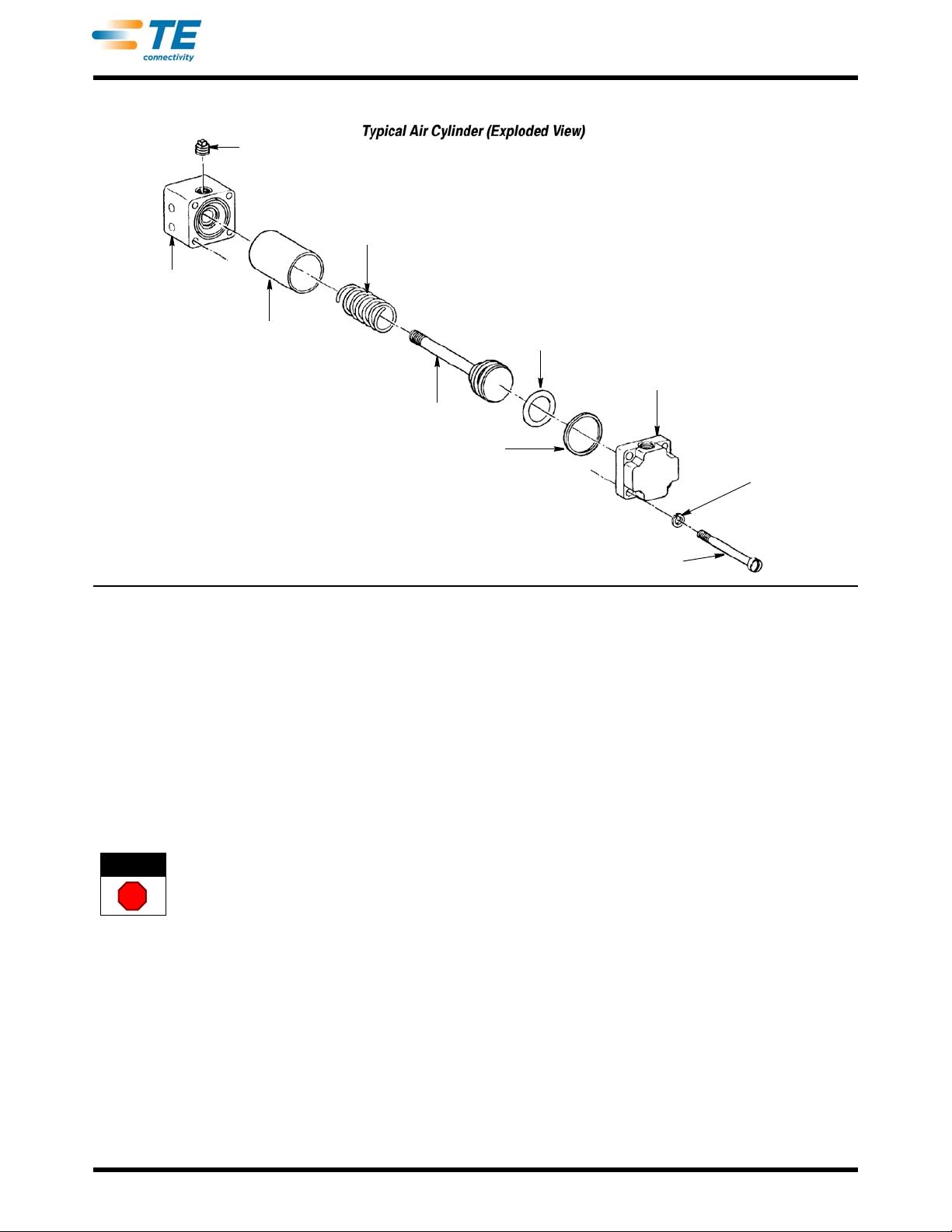
Plug
Spring
End
Cylinder
Shell
Spring
Piston
“O" Ring
Gasket
Piston End
Tie Rod Screw
Washer
409-5128
DANGER
STOP
10.4. Air Blast Assemblies (Figure 31) A. Description
Three air blast assemblies (455350-1 through -3) are available as accessories for use with standard
applicators. The -1 assembly is used with air feed applicators, the -2 assembly is used with mechanical feed
applicators with 15.87 mm [.625 (5/8) in.] or LESS feed stroke, and the -3 assembly is used with mechanical
applicators with 15.87 mm [.625 (5/8) in.] or MORE feed stroke. The on-off valve on either assembly is
"closed" when the machine is in the rest position, and is actuated "open," then "closed" again during the
machine cycle to supply an air blast to the tooling area of the applicator to remove chips. The valve is
actuated by an operating arm installed on the feed arm drive shaft of the machine.
B. Adjustments
To avoid personal injury, ALWAYS disconnect electrical and air supply before attempting any adjustments.
1. Make sure machine is at TOP-DEAD-CENTER. If nec
2. Connect air supply. If valve is not closed, loosen two screws in ope
drive shaft until valve closes, and then tighten screws.
3. Hand-cycle machine through one com
the bottom of its stroke, then close again on the u pward stroke. If not, re-adjust arm as required to obtain this
condition.
4. If a flow control valve is used, adjust for desired volume of air.
5. At completion of adjustment, disconnect air supply.
Figure 30
essary, hand-cycle it to obtain this condition.
plete cycle. Valve should open to supply an air blast as ram reaches
rating arm and rotate arm on feed arm
Rev Z
51 of 61
Page 52

409-5128
C. Replacement
There are no special procedures required for the replacement of part s in the air blast assemblies. Refer to the
exploded view and parts list for detail parts.
ITEM PART NUMBER DESCRIPTION QTY
- - - 455350-1 • BLAST ASSEMBLY, Air (For Applicator with Air Feed) - - -
- - - 455350-2 • BLAST ASSEMBLY, Air (For Applicator with Mechanical Feed, .625 in. Max) - - -
- - - 455350-3 • BLAST ASSEMBLY, Air (For Applicator with Mechanical Feed, .625 in. Min) - - -
1- 27319-4 TUBING, Plastic, 1/4 in. Outside Diameter, 152 mm [6 in.] (Assembly -1) 1
2 22295-8 FITTING, Male, 1/4 in. NPT X 1/4 in. Tube (Assembly -1) 2
3 22309-2 TEE, Female Branch, 1/4 X 1/4 X 1/4 in. NPT (Assembly -1) 1
4 22304-4 NIPPLE, Hex, 1/4 X 1/8 in. NPT (Assembly -1) 1
5 23054-1 VALVE, Flow Control (Assembly -1) 1
6 22304-1 NIPPLE, Hex, 1/8 in. NPT (Assembly -1) 1
7 22306-2 ELBOW, Street, 1/4 in. NPT (Assemblies -2 and -3) 1
8 22312-4 ADAPTER, 1/8 X 1/4 in. NPT (Assemblies -2 and -3) 1
9 22306-1 ELBOW, Street, 1/8 in. NPT (Assembly -1) 1
10 3-21000-5 SCREW, Skt Hd Cap, 10-32.50 in. L 2
11 21899-2 WASHER, Flat, No. 10 2
12 21018-7 NUT, Hex, 10-32 1
13 3-21000-6 SCREW, Skt Hd Cap, 10-32 X .625 in. L 1
14 23018-1 VALVE, On-Off 1
15 3-21000-4 SCREW, Skt Hd Cap, 10-32 X .375 in. L (Assembly -2) 2
16 811314-1 PLATE, Valve Mounting (Assembly -2) 1
17
18 452899-2 BRACKET, Mounting (Not Supplied with Assembly -1) 1
19 22306-3 ELBOW, Street, 1/8 in. NPT (Assemblies -2 and -3) 1
• Recommended Spare Parts
378393- ARM, Operating (Assemblies -1 and -3) 1
811210-1 ARM, Operating (Assembly -2) 1
Rev Z
Figure 31 (Cont’d)
52 of 61
Page 53
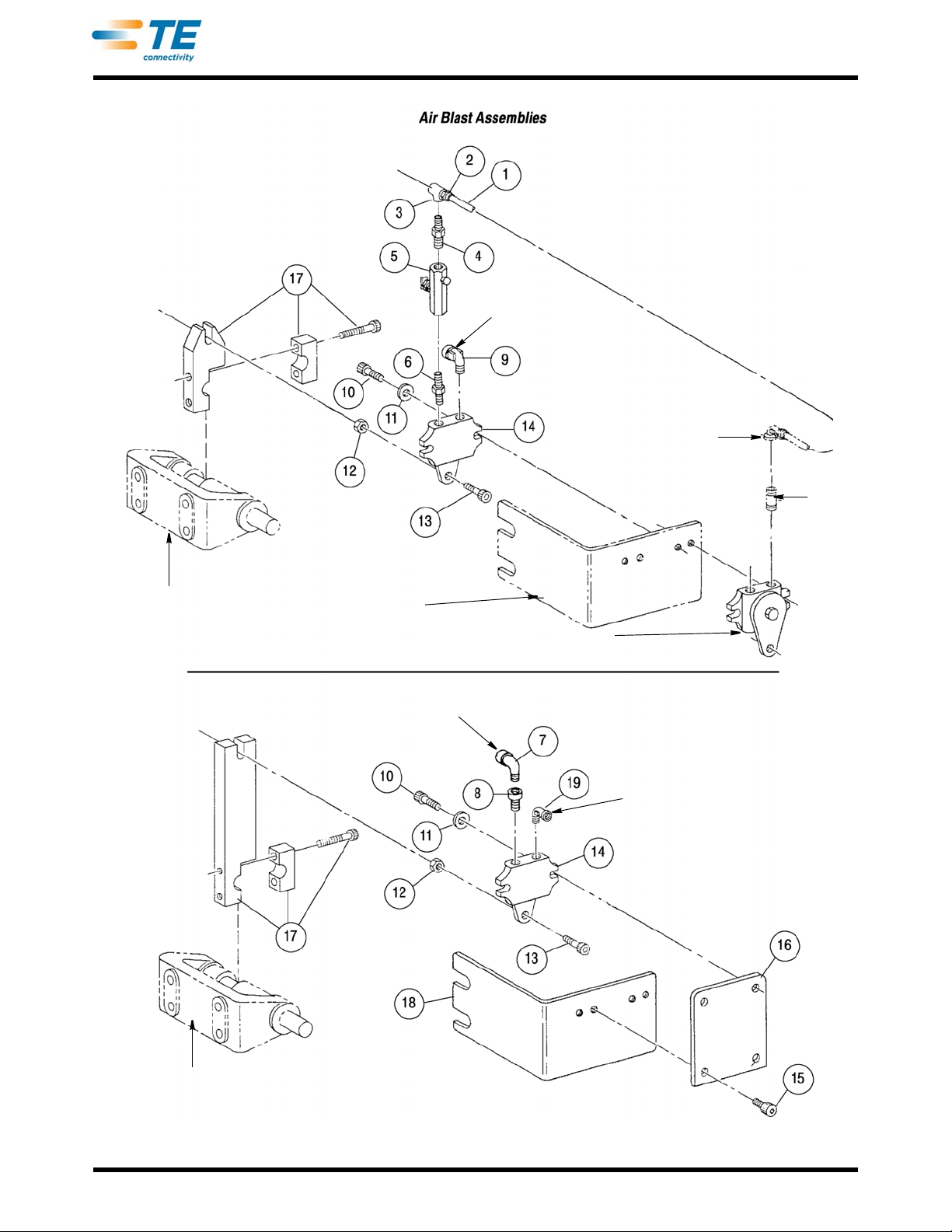
Feed Arm Drive Shaft
and Bracket (Ref)
Assembly 455350-1
Assemblies 455350-2 and -3
Ref
Ref
Air Blast (OUT)
Feed Arm Drive Shaft
and Bracket (Ref)
Air Supply (IN)
Ref
Air Supply (IN)
Air Blast (OUT)
Air Feed Valve (Ref)
409-5128
Rev Z
53 of 61
Page 54

409-5128
10.5. Optional Reel Bracket Assemblies and Associated Parts (Figure 32) A. Description
Left-Hand Reel Bracket Assembly 694925-2 is used with the vertical reel bracket assembly supp lied with the
basic machine. This assembly is required when the terminal strip must enter the applicator from the left side of
the machine. It is attached to the vertical reel support with two thumbscrew knobs for easy removal and
installation. The assembly is included in Conversion Kit 690675 -2 covered by 408-8022.
The 30° vertical reel bracket mount is required for mount
ing the vertical reel bracket assembly to the machine
frame when applicators are at a 30° angle on the machine base mount.
Horizontal Reel Bracket Assembly 692613-1 is required when the
terminal strip must be fed into the applicator
vertically and from the left side of the machine. It may be necessary to drill and tap the machine frame, as
shown, to install the assembly. This assembly , supplied as Conversion Kit 692613-1, is also covered in
408-8022.
Dual Conversion Kit 694925-4 is required to convert the ve
rtical reel bracket assembly , supplied with the basic
machine, to two-reel capabilities. As noted on the illustration, certain parts on the vertical reel bracket
assembly must be removed to install the conversion kit, while other parts are re-installed in the same location
but in a different manner . The terminal strips from both reels are fed around and throu gh the dual-stock gu ide,
and into the applicator.
Reel Spreader Assembly 453596-1 is used with the vertical reel bracket assembly. The purpose of the
a
ssembly is to spread the sides of the reel to prevent terminals or strip from being deformed as it is being
unreeled. Holes for mounting the assembly ar e pr ed rille d in the ver tic al re el sup p ort.
B. Replacement
There are no special procedures required for the replacement of parts. Refer to the illustration and parts list in
the supplied drawings for detail parts when replacement is necessary.
ITEM PART NUMBER DESCRIPTION QTY
- - - 694925-2 BRACKET ASSEMBLY, Left-Hand Reel 1
1 27708-3 KNOB, Thumbscrew 2
2 3-21000-1 SCREW, Skt Hd Cap, 8-32 X 1.000 in. L 4
3 21018-6 NUT, Hex, 8-32 2
4 1-21899-3 WASHER, Flat, No. 8 2
5 470268-1 GUIDE, Stock 1
6 694928-2 BRACKET, Left-Hand Stock Guide 1
- - - 692613-1 • BRACKET ASSEMBLY, Horizontal Reel 1
7 3-21001-8 SCREW, Skt Hd Cap, 3/8-16 X 1.750 in. L 2
8 453602-1 BLOCK, 30° Reel Bracket Mounting 1
9 2-22789-6 SCREW, Wing Thumb, 1/4-20 X .500 in. L 2
10 465520-1 FLANGE, Reel 2
11 21007-6 SETSCREW, Skt, 1/4-20 X .500 in. L 1
12 465586-2 SHAFT, Reel 1
13 21001-3 SCREW, Skt Hd Cap, 1/4-20 X .625 in. L 2
14 386213- BLOCK, Reel Shaft 1
15 1-21001-6 SCREW, Skt Hd Cap, 5/16-18 X .500 in. L 2
16 452612-2 ARM, Reel Support 1
• Recommended Spare Part
Rev Z
Figure 32 (Cont’d)
54 of 61
Page 55
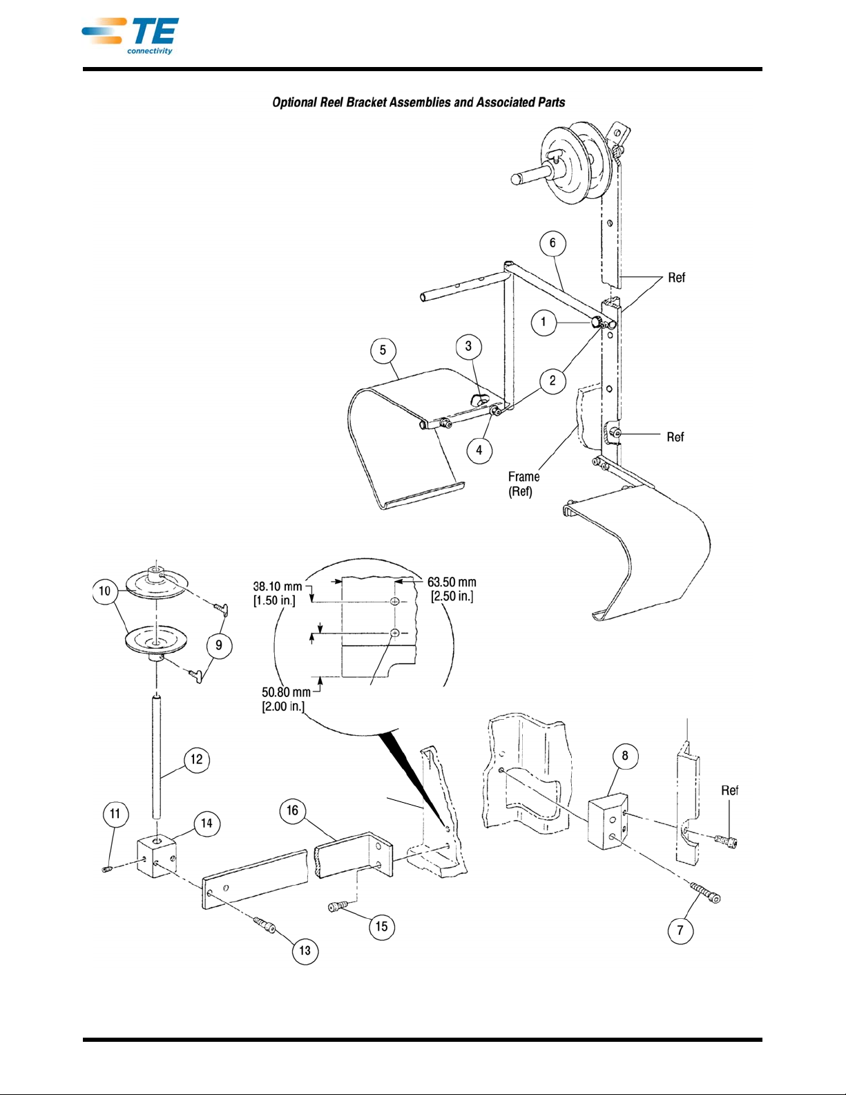
Vertical Reel Bracket
Assembly (Ref)
30° Mount
For Use with Vertical
Reel Bracket Assembly
(Items 7 and 8)
Horizontal Reel Bracket Assembly 692613-1
(Items 7 through 16)
Left-Hand Feed Reel Bracket Assembly 694925-2
Items 1 through 6 are in addition to items listed in
Figure 18 for the vertical reel bracket assembly.
Drill and Tap 5/16-18
through Frame
(2 Places)
Frame (Ref)
409-5128
Rev Z
Figure 32 (Cont’d)
55 of 61
Page 56

ITEM PART NUMBER DESCRIPTION QTY
- - - 694925-4 BRACKET ASSEMBLY, Vertical Reel, Dual Con
17 2-22789-6 SCREW, Wing Thumb, 1/4-20 X .750 in. L 1
18 457443-1 FLANGE, Reel 1
19 810578-1 FLANGE, Reel 1
20 465586-2 SHAFT, Reel 1
21 388648-5 STUD, Reel 2
22 2-21000-5 SCREW, Skt Hd Cap, 8-32 X .250 in. L 2
23 1-21899-3 WASHER, Flat, No. 8 2
24 465581-1 GUIDE ASSEMBLY, Dual Stock 1
25 2-21000-7 SCREW, Skt Hd Cap, No. 8-32 X .500 in. L 2
26 694927-2 BRACKET, Right-Hand Dual Stock Guide 2
27 3-21001-1 SCREW, Skt Hd Cap, 3/8-16 X .500 in. L 2
28 453601-1 PLATE, Dual Reel Support Mounting 1
- - 453596-1 SPREADER ASSEMBLY, Reel, 24-in. 1
29 21018-8 NUT, Hex, 10-24 1
30 21899-2 WASHER, Flat, No. 10 1
31 21004-2 SCREW, Skt Hd Shldr, .250 X .500 L Shldr X 10-24 X .375 in. L Thd 1
32 25170-1 CATCH, Bullet 1
33 2-21002-1 SCREW, Btn Hd Cap, 8-32 X .375 in. L 2
34 21018-6 NUT, Hex, 8-32 2
35 453597-2 BLOCK, Fulcrum 1
36 453599-1 SHIELD, Roller 1
37 1-21018-2 NUT, Hex, No. 5 6
38 1-21899-4 WASHER, Flat, No. 5 8
39 8-21000-4 SCREW, Skt Hd Cap, 5-40 X 875 in. L 2
40 22498-1 BEARING, Ball 2
41 453598-2 PLATE, Roller 1
• Recommended Spare Part
version Kit (See Illustration) 1
409-5128
Rev Z
Figure 32 (Cont’d)
56 of 61
Page 57
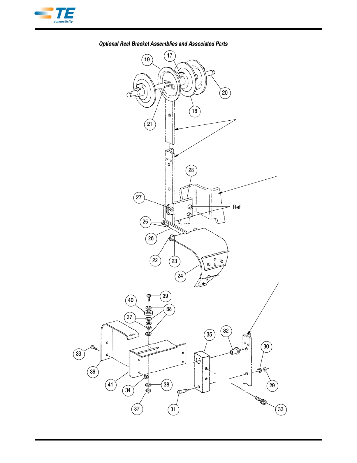
Dual Conversion Kit 694925-4
Items 17 through 28 are added to the
vertical reel bracket assembly.
Refer to Figure 18, and remove Items 3, 4,
and 6 through 10 before installing the kit.
Vertical Reel Bracket Assembly (Ref)
Frame (Ref)
Reel Spreader Assembly 453596-1
For Use with Vertical Reel Bracket Assembly
(Items 29 Through 41 and Reference)
Vertical Reel Bracket
Assembly (Ref)
409-5128
Rev Z
Figure 32 (End)
57 of 61
Page 58
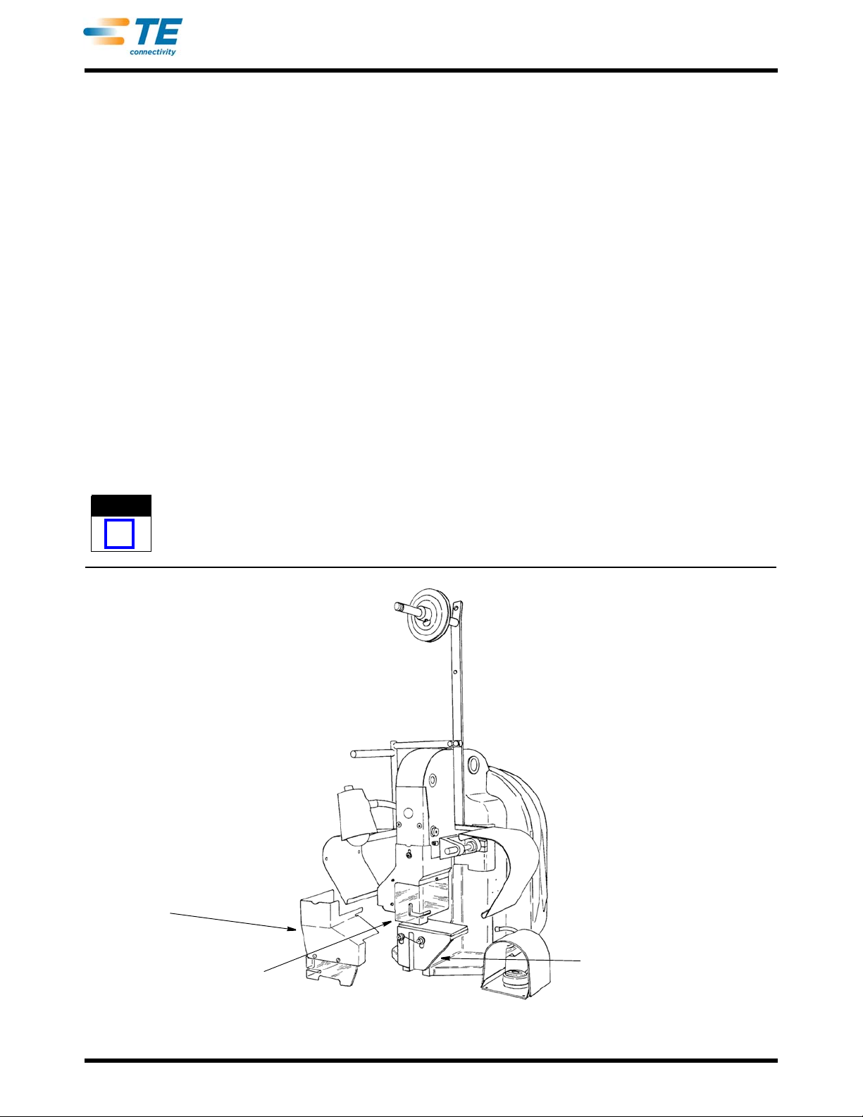
409-5128
NOTE
i
Machine 565435-5
Side-Feed
End-Feed
Solid Base
11. MODIFIED MACHINES
Modified Model "K" machines presented in this section are factory-pr epared unit s that consist of a basic machine
(as covered in Sections 1 through 9) plus one or more of the accessories descr ibed in Section 10. Each diff erent
type of modified machine has its own part number which distinguishes it from the other factory-modified versions
and from the basic machine.
A modified machine is not a complete, production-ready unit. Rather
given type of applicator. An applicator parts list is supplied with each applicator used in these Model "K"
machines, and this list includes the part number that identifies the modified configuration that the applicator
requires.
If a modified machine in the customer's plant carries the p
configuration does not agree with the modified machine part number on the nameplate, this indicates that the
machine has been changed (at least once) since it left the facto ry. These changes could have involved the
accessories covered in Section 10 or the available conversion kits.
art number for the basic machine, or if the modified
, it is a basic power unit, set up to accept a
11.1. Machine 565435-5 and 565435-2 (Figure 33)
These machines accepts both end-feed and side-feed miniature quick-change applicators. Information
contained in Sections 1 through 9 for the basic machine is applicable to these machines with one exception.
Beginning with machine revision "AD," an adjustable UNIBAL assembly (813725-1) replaces the spherical
bearing link (Item 19, Figure 20).
Components and part s added to the basic m achine, prior to re
side-feed and end-feed guards, and lef t strip guide as listed in 408- 8022. Beginning with revision "AD," the base
mount and plate have been replaced with a solid base assembly (812286-1) as shown in Figure 33, and the
machine frame has been modified. All other parts remain the same as listed in 408-8022.
vision "AD," include a base mount and plate, ram,
No machines in the field can be converted to the solid base assembly, nor can a machine shipped from the factory with a
solid base assembly be converted to another configuration.
Rev Z
Figure 33
58 of 61
Page 59

11.2. Machine 1-565435-7 (Figure 34)
This modified machine accepts miniature quick-change applicators that mount on the machine at a 30°
angle.The terminal strip enters the app licator from the right, but with the terminals in a vertical position.
409-5128
Several minor changes have been made to the basic mach
ine, as covered in Section 1 through Section 9.
Changes include the deletion of the vertical ree l brac k et asse mb ly, and the addition of a horizontal reel bracket
(on the right side), a base mount and plate for mounting the 30° applicator and ram as shown in the explod ed
view.
The base mount is adjusted before shipment to the correct sh
ut-height for accepting applicators. If a base mount
adjustment is required due to the replacement of parts, refer to Section 7. For information relating to the
applicator, refer to the applicator instructions, supplied with the applicator.
ITEM PART NUMBER DESCRIPTION QTY
- - - 1-565435-7 MACHINE ASSEMBLY, Modified Machine - - -
1 2-22789-6 SCREW, Thumb, 1/4-20 X .500 in.
2 465520-1 FLANGE, Reel 1
3 21007-6 SETSCREW, Sk
4 465586-2 SHAFT, Re
5 21001-3 SCREW, Skt Hd Cap, '/4-20 X .62
6 386213 SLEEVE, Shaft 1
7 460815-1 ARM, Reel Support 1
8 3-21000-6 SCREW, Skt Hd Cap, 10-
9 690673-2 BRACKET, Hold-Down 1
10 2-21000-7 SCREW, Skt Hd Cap, 8-32 X .5
11 690674-1 STOP, Rear 2
12 4-21002-4 SCREW, B
13 4-21002-6 SCREW, Btn Hd Cap, 3/8-16 X .750 in. L 1
14 21020-3 NUT, Hex, 3/8-1
15 453254-1 PLATE, Base 1
16 453253-1 MOUNT, Base, 30° 1
17 21009-4 SETSCREW, Skt, 14-20 X .375 in.
18 690499-1 RAM 1
19 1-
Note :Item 1, Screw, Skt Hd Cap (2) and Item 2, Bracket Assembly, Vertical Reel (1) have not been installed on this modified machine.
473271-2 MACHINE ASSEMBLY, Basic Model "K" (Refer to Section 9 for Breakdown) 1‘
i, 1/4-20 X .500 in. L 1
el 1
tn Hd Cap, 3/8-16 X .500 in. L 1
6 1
Figure 34 (Cont’d)
L 1
5 in. L 4
32 X .625 in. L 2
00 in. L 2
L 1
Rev Z
59 of 61
Page 60
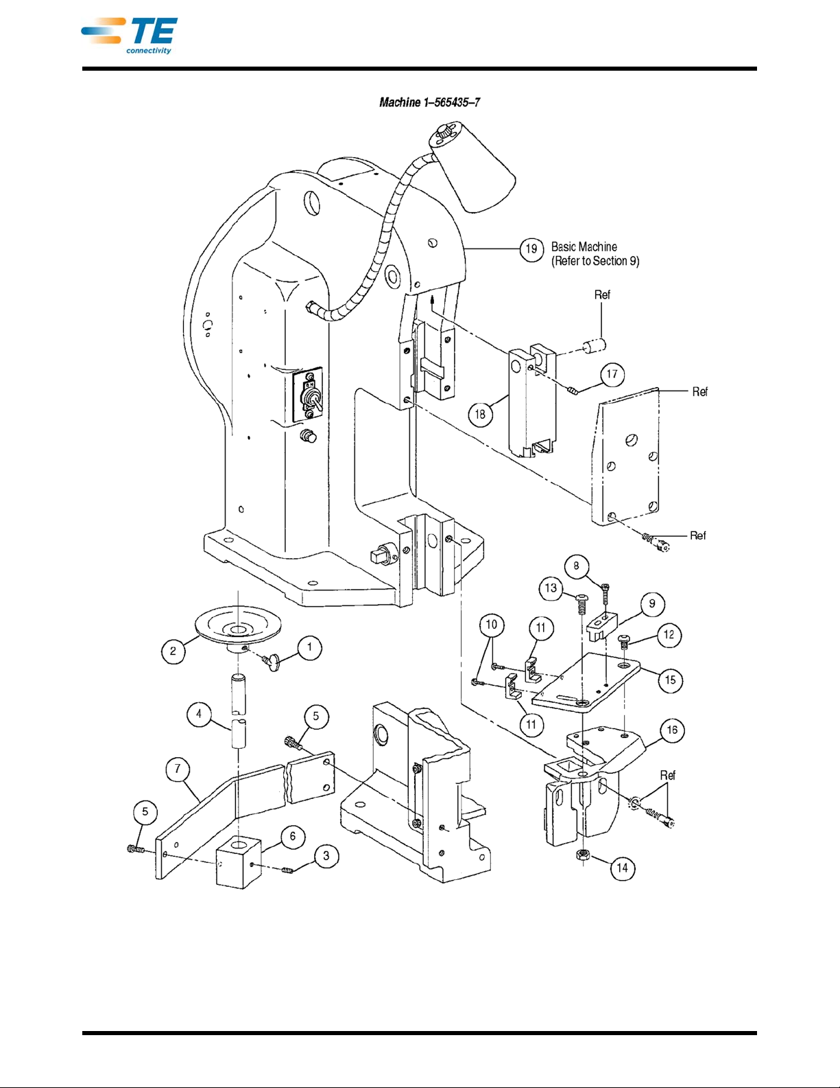
409-5128
Rev Z
Figure 34 (End)
60 of 61
Page 61

409-5128
11.3. Shut-Height Repair
It is very important that the machine has the correct shut-height (ram bottomed) for miniature quick-change
applicators to produce the specified crimp height. Each machine is adjusted at the fa cto ry prior to shipme nt an d
should never require further adjustment unless it is necessary to replace parts.
Shut-height repair should NEVER be attempted without FIRST trying another applicator that is known to
produce terminations of the correct crimp height. If this applicator produces correct terminatio ns, the trouble is in
the original applicator and the shut-height MUST NOT be changed.
A special gage MUST be used when repairing the machine shut-height, and it is recommended that this be
accomplished by a Field Service Engineer, unless a gage is available to maintenance personnel that are
qualified to make the repair
After determining that the shut-height is incorrect on a machine with an adjustable base mount (prior to revision
"AD"), refer to the adjustment procedure in Section 7. When making th e adjustme nt, place the g age on the base
mount and hand-cycle the machine to bottom the ram.
For additional information on setting the shut-height using the gage, refer to 408-9462.
12. ROHS INFORMATION
Information on the presence and location of any substances subject to RoHS (Restriction on Hazardous
Substances) can be found at the following website:
http://www.tycoelectronics.com/customersupport/rohssupportcenter/
Click on "Find Compliance Status" and enter equipment part number.
13. REVISION SUMMARY
Revisions to this customer manual include:
• changed logo and company name;
• added machine 1-565435-7
Rev Z
61 of 61
 Loading...