

Page 1
Instruction Sheet
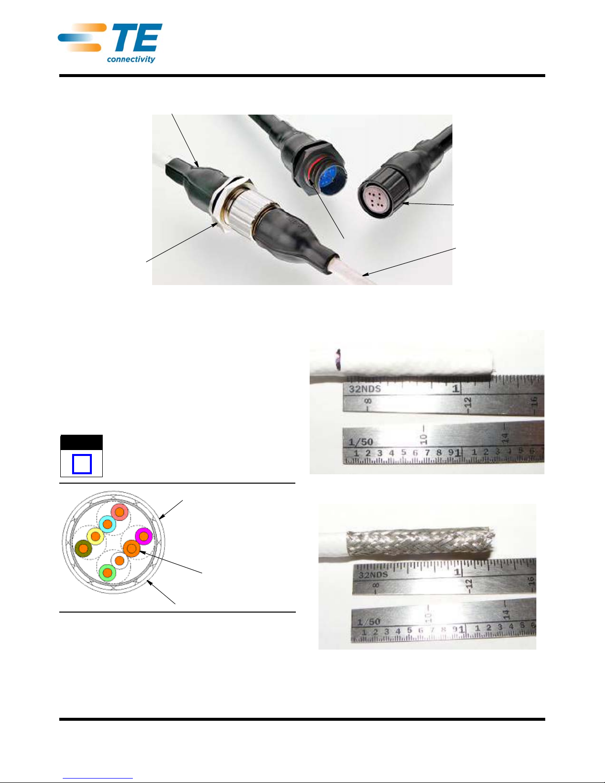
Heat Sink Boot
Jam Nut
Coupling Ring
Cat6A Cable
Full Mate Indicator
Receptacle
Connector
Plug Connector
NOTE
i
Cable O.D. Range:
5.59-10.16 mm [.220-.400 in.]
Maximum Conductor
Insulation Diameter
1.27 mm [.050 in.]
Cat6A Cable
CEELOK FAS-T* Cable Harness
Manufacturing Guide
1. INTRODUCTION (Figures 1 and 2)
The following instructions detail the steps for
terminating the CEELOK FAS-T Connector harness.
Refer to documents: Raychem RCPS-100-70
installation procedure for solder sleeve termination;
Application Specification 114-32025 for CEELOK
FAS-T High Speed Circular Connector System; and
Installation Procedure ELE-3COP-375 for braid
termination using a band strap adapter.
Dimensions in this instruction sheet are in
millimeters [with inches in brackets]. Figures and
illustrations are for reference only and are not
drawn to scale.
408-32046
02 APR 12 Rev A
Figure 1
Figure 3
Figure 2
1. Cut the cable to the desired length. Use an
appropriate cable cutter. Mark and strip
approximately 31.75 ±1.57 mm [1.25 ±.062 in.] of
cable jacket over the braid section. Refer to Figures
3 and 4.
Raychem is a trademark.
©2012 Tyco Electronics Corporation, a TE Connectivity Ltd. company
All Rights Reserved
*Trademark
TE Connectivity, TE connectivity (logo), and TE (logo) are trademarks. Other logos, product and/or Company names may be trademarks of their respective owners.
2. Fold the braid back over the cable jacket and
remove foil wrap (if it exists) to expose the internal
conductors. Refer to Figure 5.
TOOLING ASSISTANCE CENTER
PRODUCT INFORMATION
1-800-522-6752
1-800-722-1111
This controlled document is subject to change.
For latest revision and Regional Customer Service,
visit our website at www.te.com
Figure 4
1 of 6
Page 2
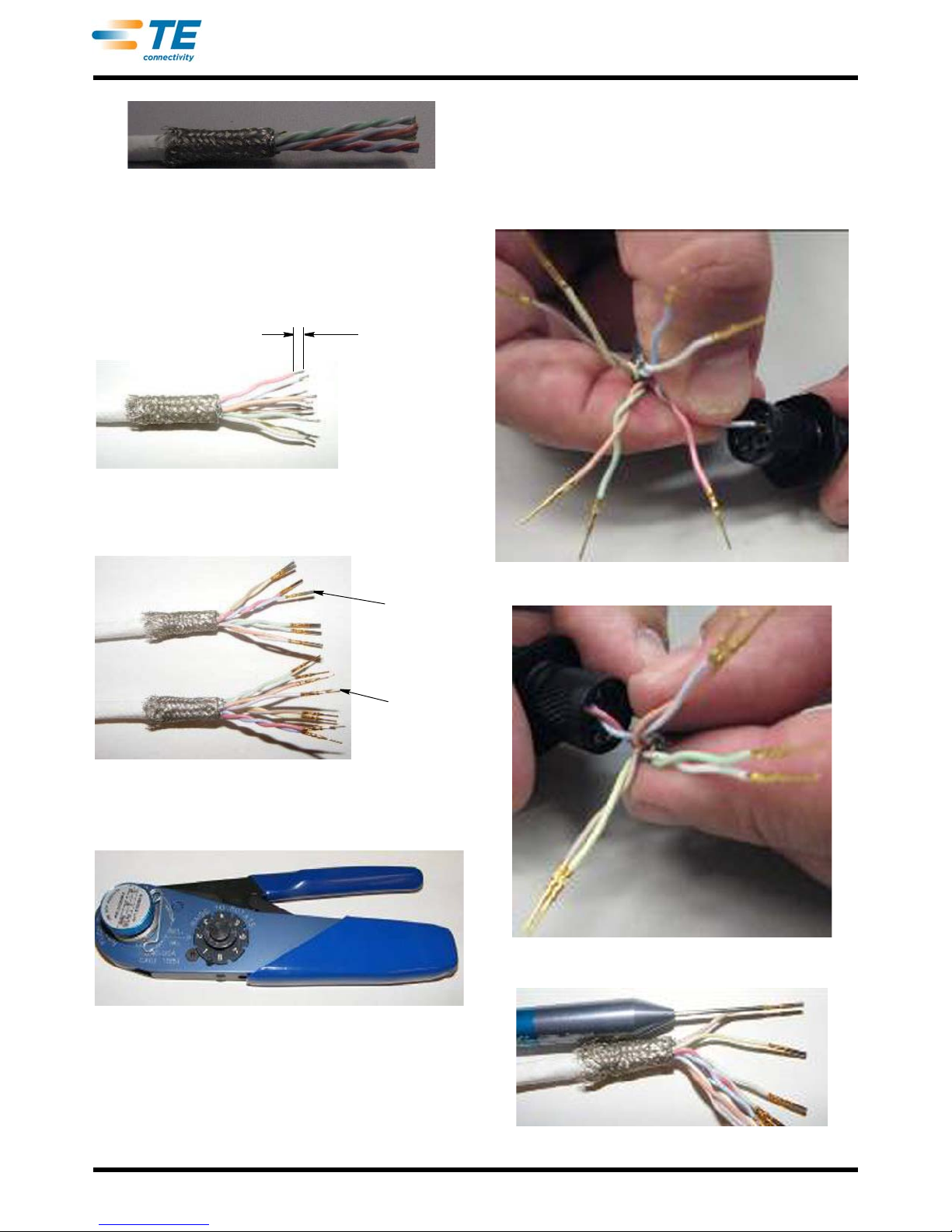
Figure 5
3.18 ±0.76
[.125 ±.030]
Socket
2102350-5
Pin
2102349-3
3. Untwist the conductor pairs and strip to the length
of approximately 3.18 ±0.76 mm [.125 ±.030 in.].
Terminate pins (2102 349-3) or socket s (2102 350-5)
to the conductors using crimp tool M22520/2-01
with positioner K1850. Refer to Figures 6 thru 8.
Figure 6
408-32046
For example, one pair should be loade d into cavities
(1 and 2), another pair in cavities (3 and 4), another
pair in cavities (5 and 6), and another pair in cavities
(7 and 8). If it is difficult to seat the contact s by
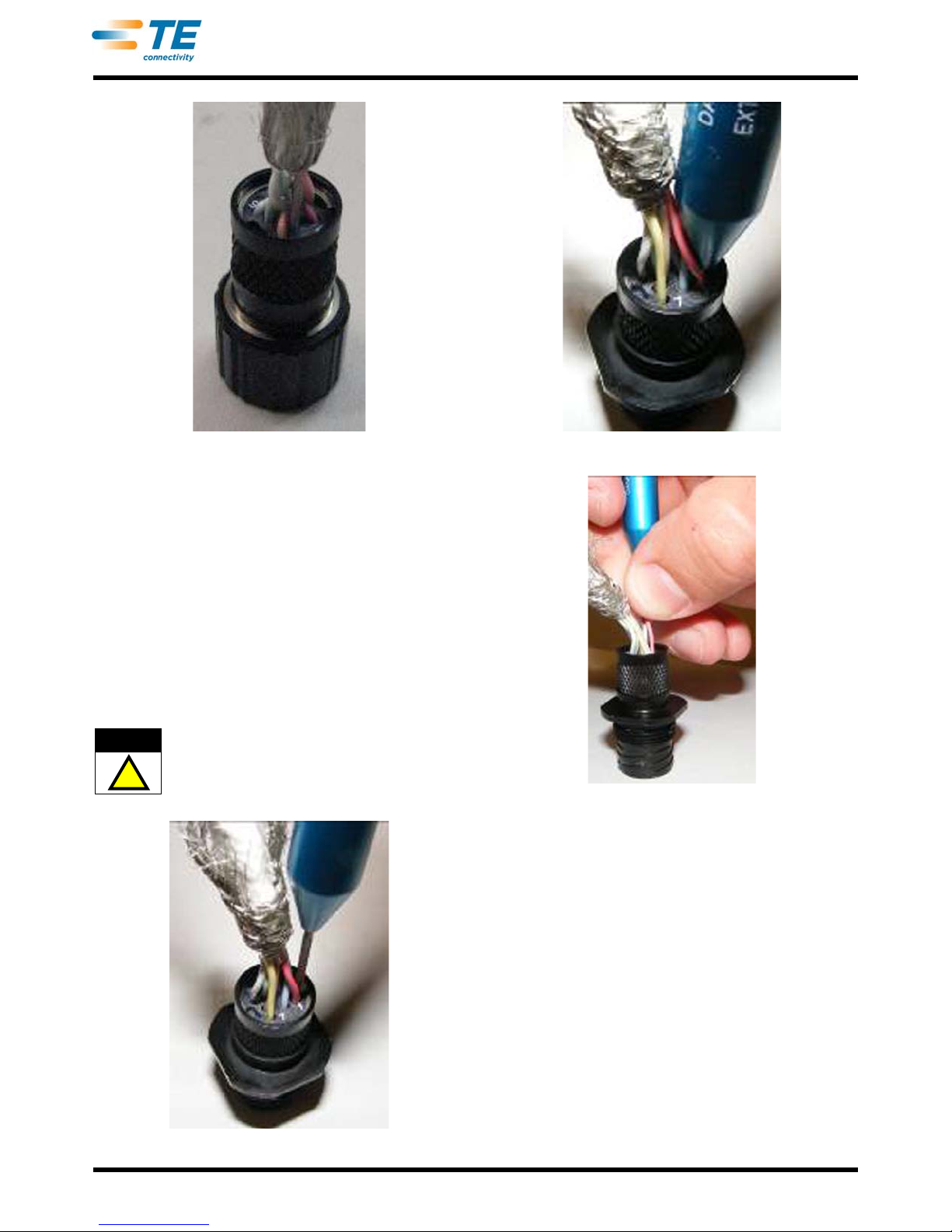
hand, the insertion tip of tool DHK696 can be used.
The tip will push on the rear of the crimp barrel of
the contact. Refer to Figures 9 thru 12.
Figure 7
Figure 8
4. Re-twist wires to include two full twists prior to
inserting them into the connector housing. Insert the
contact into the circuit cavity and push it into the
cavity until it “clicks” into place. During insertion,
care should be taken to make sure the conductor
pairs are loaded into adjacent circuit cavities.
Figure 9
Figure 10
Figure 11
Rev A
2 of 6
Page 3
408-32046
!
CAUTION
Figure 12
5. In cases where the contact needs to be removed
from the connector after it is locked in place, the
extraction tip of tool DHK696 is inserted into the
circuit cavity to engage the latching clip tine to
release it from the contact. The tip of the tool sh ould
be inserted at the outer side of the circuit cavity pair
and oriented approximately 90° to the cavity I.D.
lettering.
The tip is inserted until the handle is bottomed on
the plastic housing. the wire is then gripped and
held against the tool body as the tool is carefully
removed. The contact can then be re-inserted after
it is repaired or replaced. Refer to Figures 13
thru 15.
Be careful not to nick the wire insulation of the
conductor or damage the tool tip during tool tip
insertion.
Figure 13
Figure 14
Figure 15
6. Fold the braid back up, over the rear of the
connector body and comb out in a uniform pattern
over the knurled portion. The braid is then
terminated to the connector shell with a CRES-Lock
band strap (BND-0812-S) applied with a Micro
Tie-Dex II, A30199 hand tool.
Prepare the band for termination by looping the end,
through the buckle slot twice to create a double
wrap slightly larger than the back of the connector
shell (approximately 15.88 mm [.625 in.]). Insert the
free end of the strap into the tool termination slot
such that the looped portion of the band faces down
and the buckle is approximately flush with the tool
face.
Slide the band along the shield so that it is located
within the knurled portion of the shell.Tighten the
band by repeatedly squeezing the ratchet handle
until it locks against the tool body.
Rev A
3 of 6
Page 4
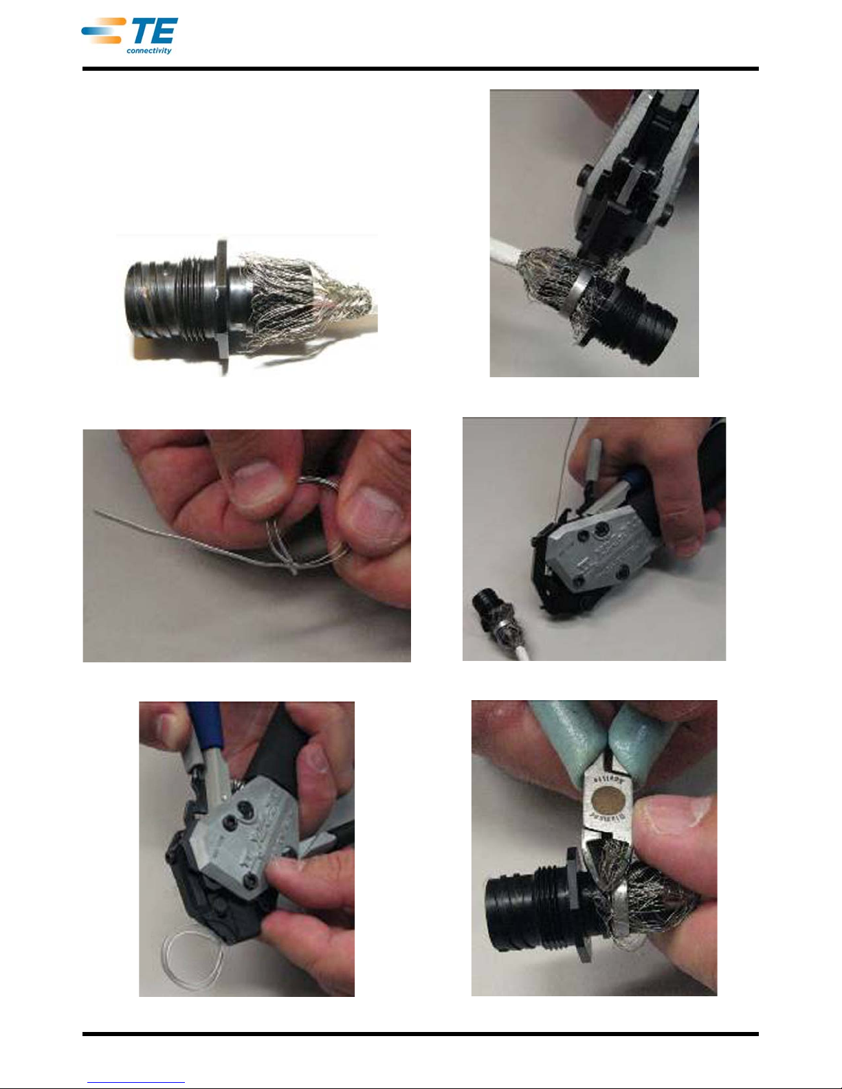
Trim the excess band by squeezing the cutoff
handle until the band shears off. Remove the
excess band from the tool by depressing the
release handle and pulling it free. Trim the excess
braid flush with the forward lip of the connector shell
at the end of the knurled portion with side cutters.
Refer to Figures 16 thru 22. For further information
on terminating band straps, refer to Installation
Procedure ELE-3COP-375.
408-32046
Figure 16
Figure 17
Figure 19
Figure 20
Figure 18
Rev A
Figure 21
4 of 6
Page 5
408-32046
6.35 [.250]
Solder
Ring
Figure 22
7. Position the heat shrink boot over the terminated
braid such that the lip end of the boot extends
beyond the raised rib on the connector shell. Apply
heat to the front of the boot uniformly until it shrinks
down and the boot lip engages th e r aised r i b o n the
connector.
Continue to apply uniform heat to the boot, working
back along its length until it is completely recovered
over the connector body and cable jacket. Refer to
Figures 23 thru 25. Additional application
instructions are included on the heat shrink boot
packaging.
Figure 25
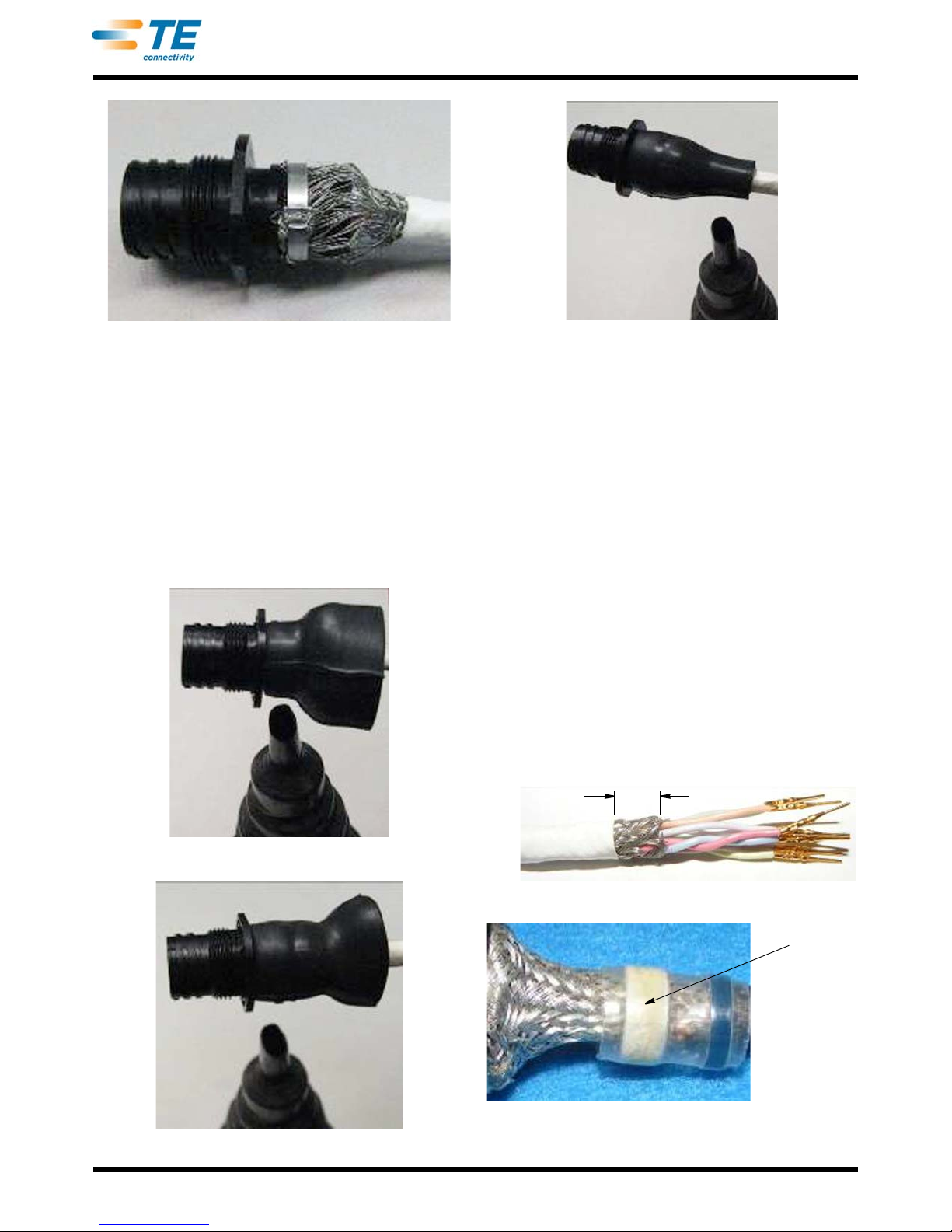
8. EMI shielding can be maximized through an
application of a braid sock termination to the
connector back shell in lieu of termination of the
cable shield directly to the connector. Follow the
cable preparation and contact crimp and assembly
procedures of Steps 1 thru 4, except strip back the
cable jacket braid so that approximately 6.35 mm
[.25 in.] is exposed.
Cut a piece of braid sock to approximately
28.58 mm [1.125 in.] in length and position it so that
one end over-laps the exposed cable braid and the
other end extends over the knurled portion of the
connector back shell.
Position a solder sleeve over the braid sock and
cable so that the solder ring of the solder sleeve is
in the area where the braid sock and cable braid
over-lap. Apply the solder sleeve with a heat gun go
that the solder ring completely reflows. Refer to
Raychem RCPS-100-70 installation procedure for
solder sleeve termination. Complete the termination
of the braid sock to the connector shell with a band
strap and apply a heat shrink boot per Steps 6
and 7. Refer to Figures 26 thru 28.
Figure 23
Figure 24
Rev A
Figure 26
Figure 27
Raychem is a trademark.
5 of 6
Page 6
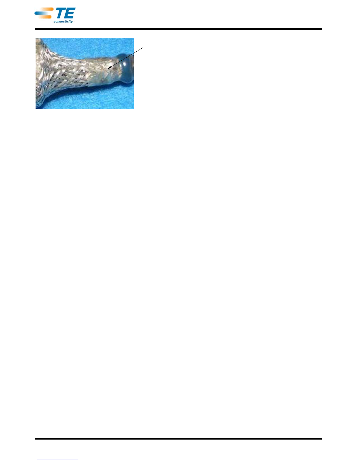
Figure 28
Reflowed
Solder Ring
408-32046
2. REVISION SUMMARY
•Initial release of document
Rev A
6 of 6
 Loading...