

Page 1
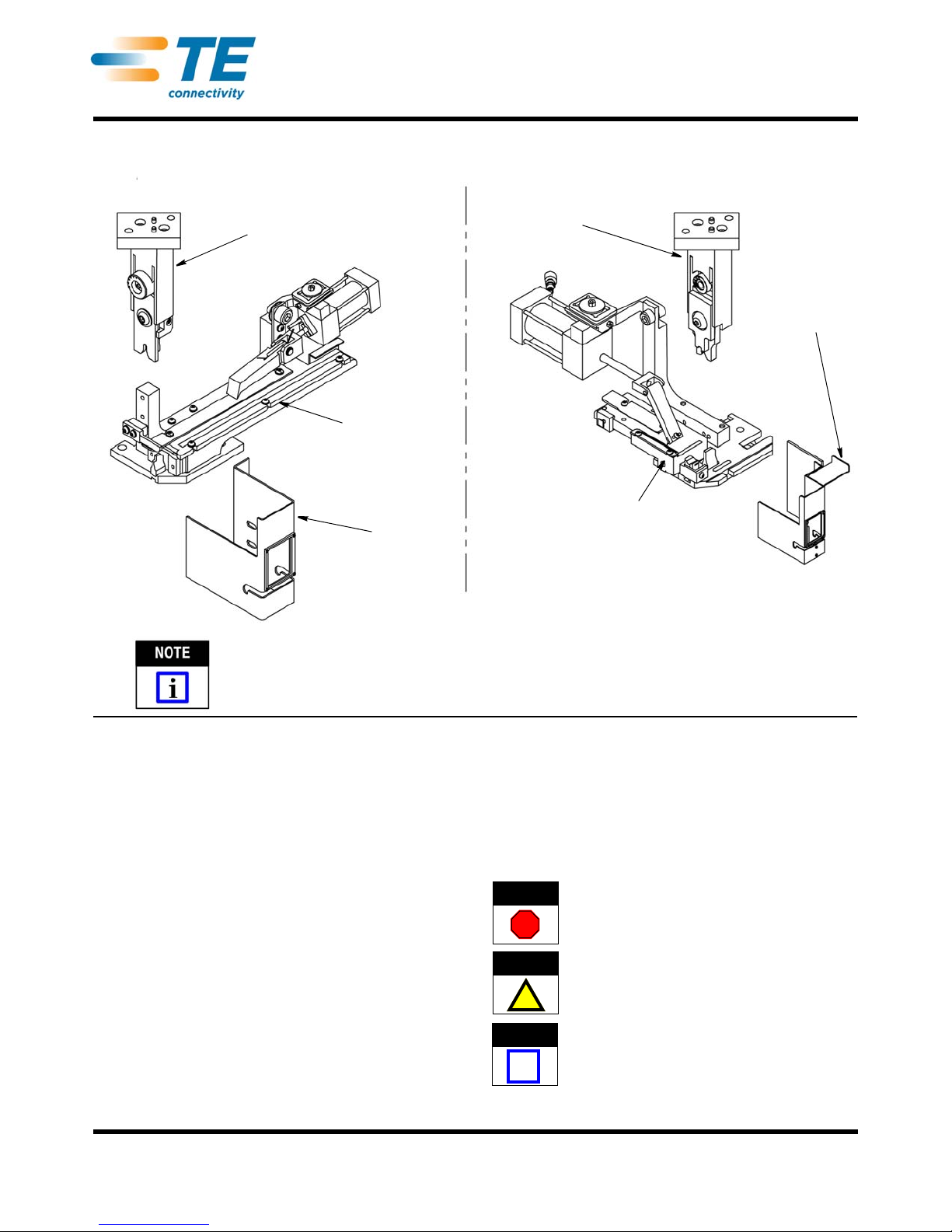
Tool Holder
Guard
Guard
Applicator Base
Tool Holder
Applicator Base
Guards on the applicator may differ from the guards shown in the illustrations.
End-Feed Through-Splice Applicator for ThroughSplice Applications in AMP 5K/40 CE Terminators
Side-Feed Through-Splice Applicator for Through-
Splice Applications in AMP 5K/40 CE Terminators
End-Feed and Side-Feed
DANGER
STOP
CAUTION
!
NOTE
i
Applicators for AMP 5K/40* CE
Through-Splice Terminators
Instruction Sheet
408-32027
08 FEB 12 Rev A
ORIGINAL INSTRUCTIONS
1. INTRODUCTION
Side-Feed and End-Feed Through-Splice Applicators
(Figure 1) for AMP 5K/40 CE Through-Splice
Terminators apply strip terminals to pre-stripped wires.
Each
applicator accepts the strip form of certain
terminals, which are identified on the applicator parts
list and exploded view drawing (Applicator Log) for
each applicator. The terminal listed on the applicator
data plate is the one that was specified when the
applicator was ordered. Some terminals have two
carrier strips, others just one.
Additionally, these instructions cover the differences
b
etween the AMP 5K/40 CE through-splice terminator
for through-splice terminals (Figure 1) and the
AMP 5K/40 CE Terminator 2161500-[ ] for end of wire
a
pplications.
Refer to customer manual 409-10204 for general
ma
chine information about the AMP 5K/40 CE
Terminating Machines.
Figure 1
This instruction sheet, the parts list and the exploded
view dra
wing packaged with the applicator and
409-10204 provide all the information required to
op
erate and maintain the applicator and machine
When reading this document, pay particular attention
to DANGER, CAUTION, and NOTE statements.
Denotes an imminent hazard which may result in
moderate or severe injury.
Denotes a condition which may result in product or
equipment damage.
Highlights special or important information.
.
© 2012 Tyco Electronics Corporation, a TE Connectivity Ltd. Company
All Rights Reserved
*Trademark
TE Connectivity, TE connectivity (logo), and TE (logo) are trademarks. Other logos, product and/or Company names may be trademarks of their respective owners.
TOOLING ASSISTANCE CENTER
PRODUCT INFORMATION
1-800-522-6752
1-800-722-1111
This controlled document is subject to change.
For latest revision and Regional Customer Service,
visit our website at www.te.com
1 of 11
LOC B
Page 2
NOTE
i
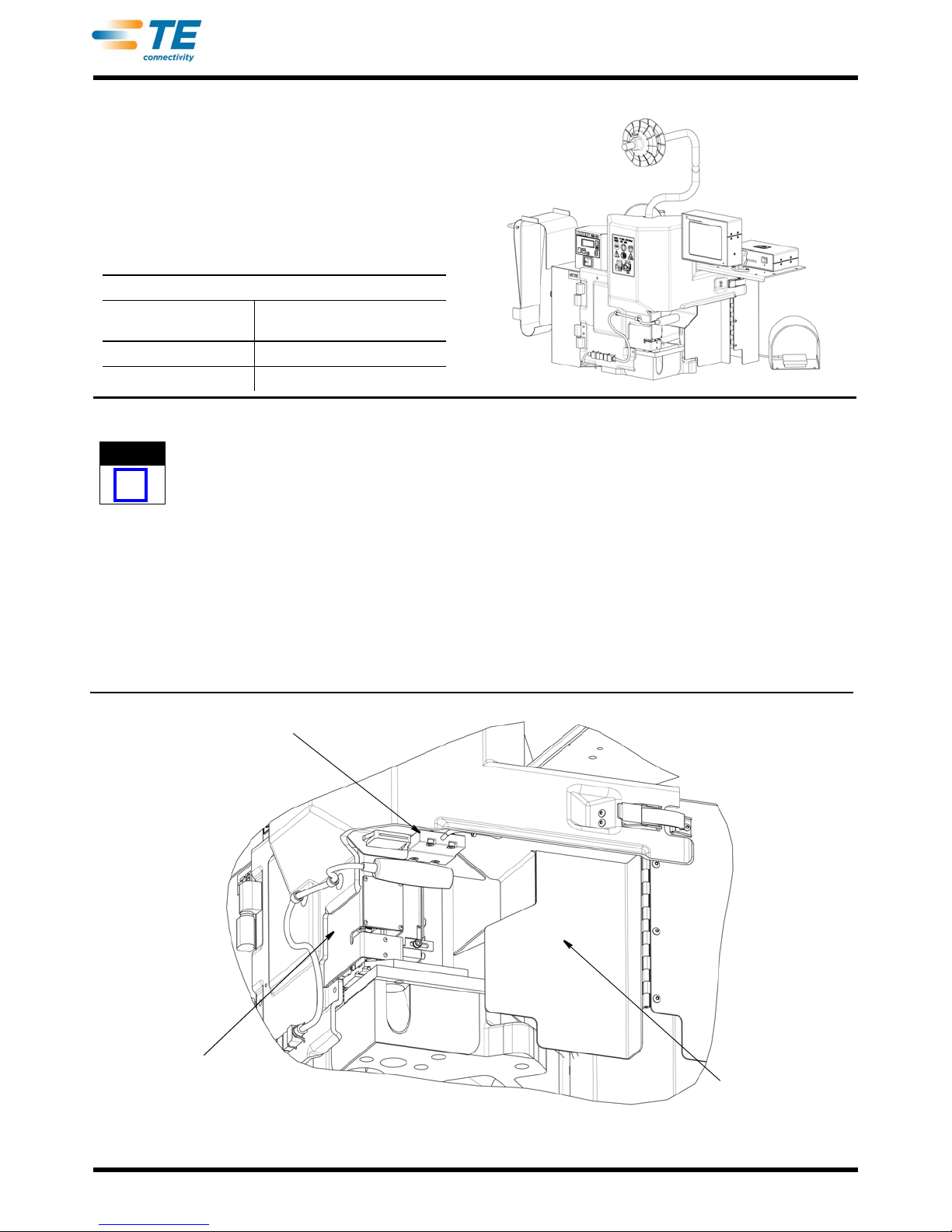
Applicator Guard Safety Switch
Hinged Guard Door
Applicator Guard
AMP 5K/40 CE TERMINATOR
TERMINATOR PART
NUMBER
2161300-1 Machine (Base)
2161300-2 Machine w/ CQM II
DESCRIPTION
408-32027
Figure 2
Dimensions in this document are in metric units
[with U.S. customary units in brackets
2. DESCRIPTION
2.1. Terminator Description
The AMP 5K/40 CE Through-Splice Terminator
(Figure 2) was designed to be used as a stand alone
semi-automatic bench machine. The modifications
d
escribed below allow application of through-splice
terminals and other terminals that require access to
both sides of the wire crimper.
The guards of the standard AMP 5K/40 CE Terminator
ha
ve been modified to allow access to both sides of
the crimper for through-splice type applications. Refer
to Figure 3. These guards work together with the
applicator guards to protect the operator. The left and
r
ight guards are deeper to allow for the long air feed
end feed applicators. Attached to the right guard is a
hinged metal guard. A safety switch is mounted on the
hinged guard that is actuated by a magnetically
encoded switch actuator mounted on the applicator
guard. The terminator will not cycle without the
applicator guard in place.
Rev A
Figure 3
2 of 11
Page 3
408-32027
NOTE
i
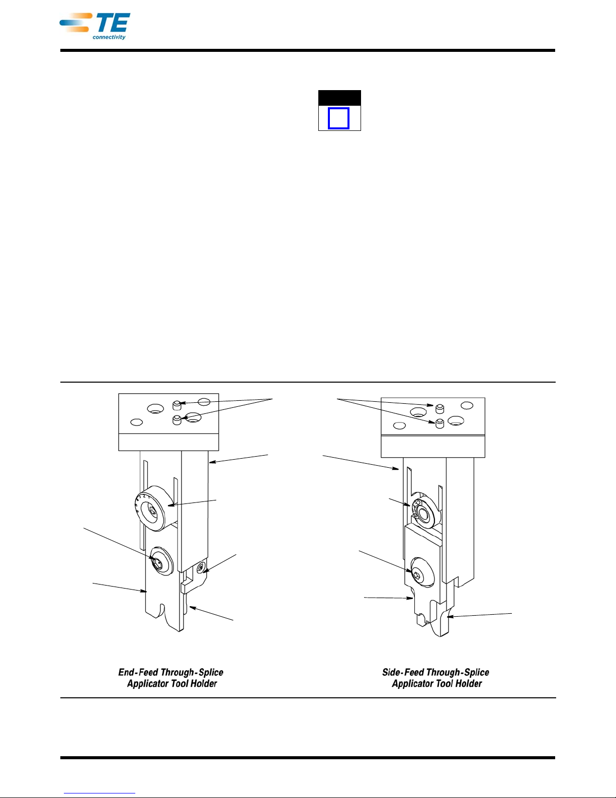
Locating Pins
Tool Holder
Crimp Height
Adjustment Wheel
Hold-Down
Bracket
Shear Blade
Crimper
Bolt
Wire
Crimper
Front Shear
Depressor
Crimp Height
Adjustment Wheel
Wire
Crimper
Crimper
Bolt
The front guard has been modified to remove the
guard insert. The front guard works together with the
applicator guarding to protect the operator. The front
guard retains its keyed interlock to actuate the guard
safety switch when closed.
The modified guards on the AMP 5K/40 CE throughslice terminator will work with side-feed and end-feed
CE through-splice applicators.
2.2. Applicator Description
End-Feed and Side-Feed applicators used with AMP
5K/40 CE through-splice terminators are two-piece
applicators consisting of a tool holder and applicator
base.
The tool holder is secured to the ram of the AMP
5K’/40 Through-Splice Terminating Machine with
screws. The tool holder contains locating pins
(Figure 4) to facilitate it's location on the
ram. The locating pins allow an easier tooling
cha
ngeover.
The wire crimper , insulation crimper, and the front
sh
ear depressor are located in a pocket in the tool
holder, and are secured by a crimper bolt. The front
shear depressor pushes the front floating shear down
to cut the crimped terminal from the strip.
terminator
two
The wire crimp is easily adjusted, providing an array of
dif
ferent wire crimp sizes.
All AMP 5K/40 CE Through-Splice Terminators are
equipped with a "precision adjust" feature.
The hold-down bracket (see Figure 4) is attached to
the ram and, with bracket attached, holds the terminal
in p
lace during the crimping and shearing process.
The applicator's mounting surface is it
The base plate attaches to the base of the terminator.
The anvil, shear tooling and strip guide plates are all
located on the base plate.
Since the upper tooling is p
lower tooling can be adjusted to the correct position
and locked (screwed) into place.
End-Feed and Side-Feed Through-Splice Applicators
can
withstand the high crimping pressures required to
apply terminals to the larger CMA ranges (up to
approximately 17,000 CMA ). Although these
applicators accept only certain terminals, they provide
valuable application flexibility. The design optimizes
accessibility which aids in more precise wire
placement, and increased production throughout.
ermanently located, the
s base plate.
Rev A
Figure 4
3 of 11
Page 4
408-32027
NOTE
i
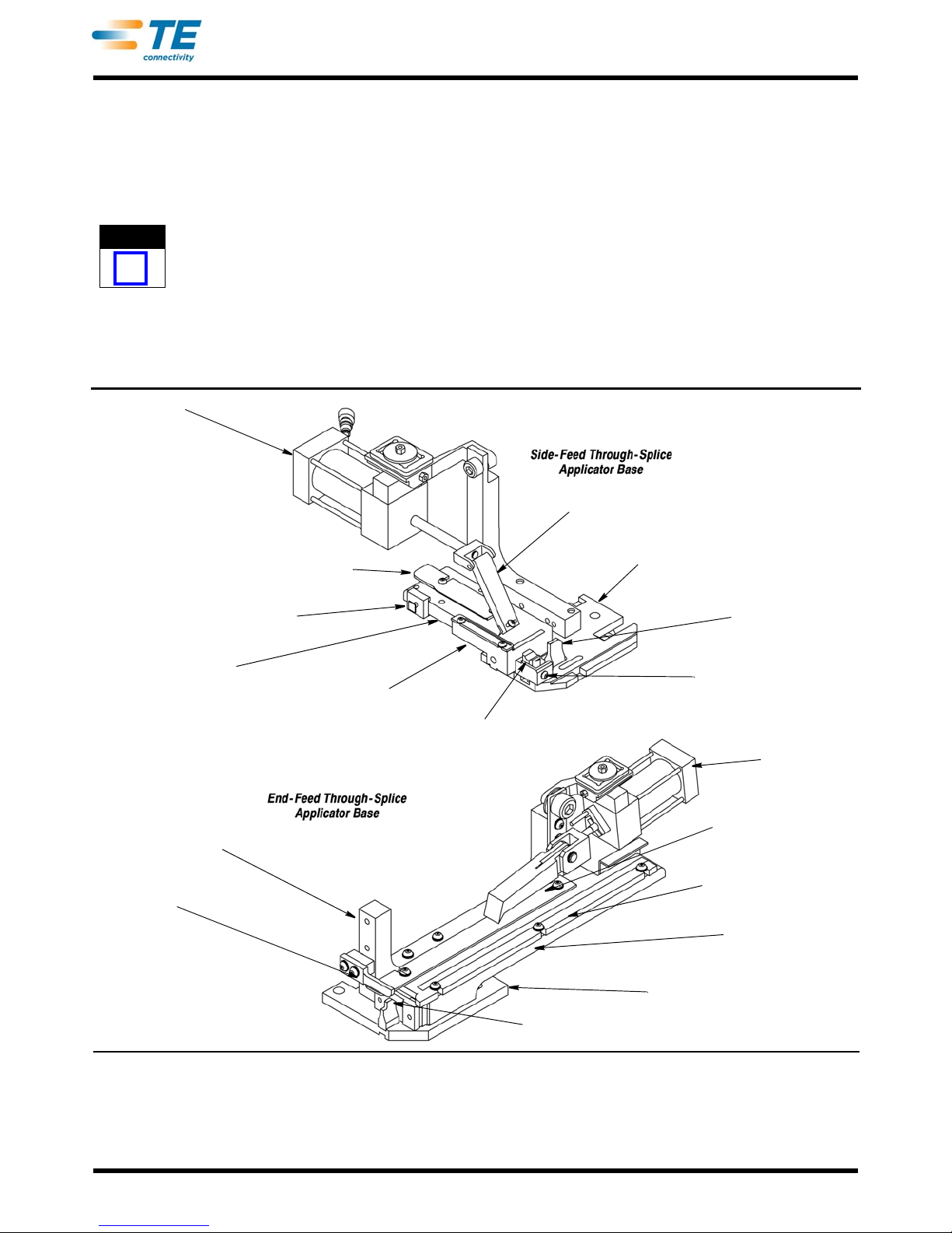
Feed Cylinder
Front Strip Guide
Strip Guide Plate
Strip Guide
Adjusting Block
Terminal Drag
Shear Retaining Screw
Anvil
Applicator
Base Plate
Feed Finger
Feed Bracket
Stripper
Anvil
Applicator
Base Plate
Strip Guide Plate
Front Strip Guide
Rear Strip Guide
Floating Shear
Feed Finger
Feed Cylinder
Terminal strip is fed into the applicator with the barrel
(wire) end first, between the front (outer) and rear
(inner) strip guides. It passes the stock drag, and the
LEAD terminal is positioned over the anvil. The feed
pawl feeds one terminal during each cycle of the
machine. The terminals are fed by the action of the air
cylinder that is controlled by a valve on the terminator.
Some applicators have a solid metal hold-down
that may require adjustment when changing the
wire size and/or crimp height.
Terminals with dual-carrier strips require a shear
d
epressor, spacer, and terminal holder. These parts
are also attached to the tool holder assembly. The rear
shear depressor pushes the rear floating sh ea r do wn
to cut the terminal from the rear carrier strip, and the
terminal holder keeps the terminal from raising during
the crimping and shearing process.
The anvil, the front shear holder, the rear shear holder
(
if used), the terminal support, and the strip guide
adjustment block are mounted on the base plate, as
well as the rear floating shear and rear shear holder.
The strip guide plate (Figure 5) is fastened to the strip
guide adjustment block. The stock drag, the s tri p
gu
ide cover plate, and the front and rear strip guides
are mounted on the strip guide plate.
The applicators used for the through-splice application
ar
e PRE-FEED Applicators. This means that the lead
terminal is over the anvil when the machine is at rest.
Rev A
Figure 5
4 of 11
Page 5
408-32027
CAUTION
!
DANGER
STOP
DANGER
STOP
NOTE
i
DANGER
STOP
DANGER
STOP
3. APPLICATOR INSTALLATION AND REMOVAL
With the applicator in the machine, NEVER attempt
to cycle machine under power WITHOUT terminals
properly loa
ded, as described in Section 4;
otherwise, the tooling may be damaged.
3.1. Applicator Installation
To avoid personal injury , be SURE the terminator is
turned off and power to the machine is
disconnected BEFORE installing or removing the
applicator
.
A. Tool Holder Installation
To properly install Through-Splice Applicator first
install the tool holder.
1. Position the tool holder on the bottom of the
ter
minator ram using the two locating pins shown in
Figure 4.
2. Secure the the tool holder into position with two
cap screw
s.
B. Applicator Base (Lower Tooling) Installation
Align the applicator base to the terminator and the tool
holder and secure the base plate to the terminator
base as follows:
1. Align the lower tooling to the upper tooling (tool
ho
lder with the crimper installed) In the side-to-side
direction.
To avoid personal injury , be SURE the terminator is
turned off and power to the machine is
disconnected BEFORE installing or removing the
applicator
cord from the back of the terminator. Insert a hex
wrench into back of the gearbox and turn the drive
sprocket.
a. Place the base plate of the app
base portion of the terminator and loosely install
two 6mm screws.
b. Double a piece of paper over the anvil and
lo
wer the terminator ram and tool holder so that
the crimper engages with the anvil.
c. Try to rotate the lower portion of the applicator .
It sh
ould not have any movement. If side-to-side
movement is present, lower the ram and crimper
until the base plate does not move.
If the ram is at the bottom-dead-center position
and there is
be adjusted. Refer to Paragraph 5.1, Crimp
Height Adjustment.
If the lower portion has no mo
properly located side to side.
2. Align the lower tooling to the upper tooling (tool
holder with
back direction.
. Lower the ram by removing the power
licator onto the
still movement, the crimper must
vement then it is
the crimper installed) In the front-to-
The lower tooling on the base plate is located
properly when the bellmouth on the product is
within the specified ra
nge.
3. Tighten two 6mm screws securing the applicator
base
to the terminator base.
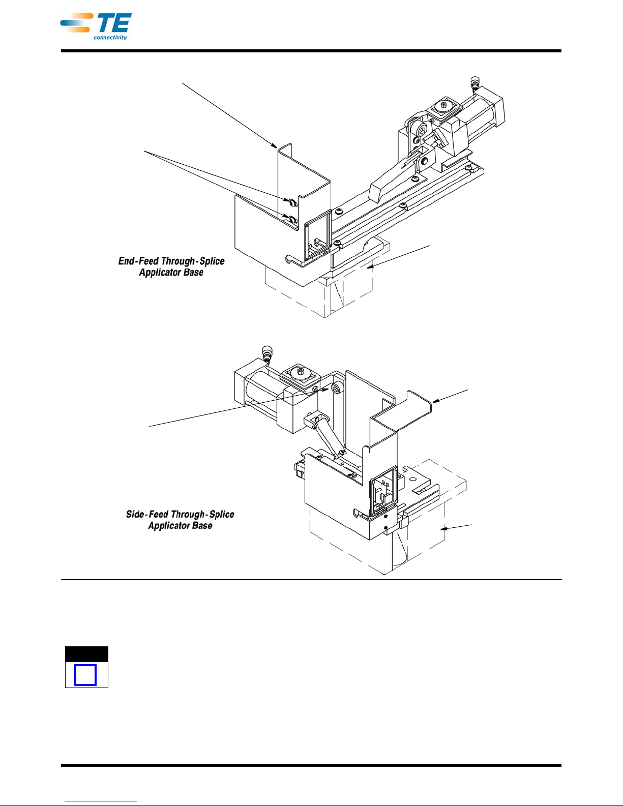
4. IInstall the wrap-around guard to the applicator
with two mounting s
crews.
5. Be sure the appropriate plexi-glass guard is
inst
alled on the terminator.
Refer to customer manual 409-10204 for hand-cycling
instruc
tions.
3.2. Applicator Removal
To avoid personal injury, Be SURE power to the
machine is turned "off" (or power cord is
disconnected) BE
FORE installing or removing the
applicator.
1. Turn machine "off" and disconnect power cord.
2. Remove the wrap-around guard by removing the
tw
o mounting screws. Refer to Figure 6.
3. Remove the product strip from the applicator.
4. Remove two 6mm screws that secure the
ap
plicator base to the terminator.
5. Slide the applicator base clear .
6. Remove two screws that secure the tool holder to
th
e terminator ram.
7. To store the applicator
, refer to Section 8,
APPLICATOR STORAGE.
4. APPLICATOR LOADING AND UNLOADING
To avoid personal injury , be SURE the terminator is
turned off and power to the machine is
disconnected BEFORE
loading or unloading the
applicator.
4.1. Terminal Strip Loading
Before loading terminal strip in applicator, be SURE
the installed applicator is the right one for terminal to
be applied. Compare terminal number on reel with
numbers listed on applicator parts list.
1. Turn "off" and disconnect power to the terminator.
2. Be sure ram assembly is all the way up. If
ne
cessary, hand-cycle machine to raise the ram.
(Refer to customer manual 409-10204 for handcycling instructions.)
3. Open the guard doors of the terminator.
4. Raise stock drag by turning terminal drag (drag
re
lease lever) upward.
Rev A
5 of 11
Page 6
Wrap-Around Guard
Wrap-Around Guard
Mounting Screw(s)
Terminating
Machine Base (Ref)
Wrap-Around Guard
Wrap-Around Guard
Mounting Screw(s)
Terminating
Machine Base (Ref)
NOTE
i
408-32027
5. With reel of terminals installed on reel support,
feed terminal strip into applicator between strip
guides.
Be SURE terminal strip enters strip guides with
barrel (wire) end toward the stock drag and the
open side up.
Figure 6
7. Turn terminal drag downward to lower the stock
dr
ag.
8. Be sure tip of feed pawl is in feed hole in carrier
str
ip. Note that some carrier strips have additional
holes which are not used for feed purposes.
9. Close the terminator guard doors.
6. Raise feed pawl and continue to feed terminal
strip
until LEAD terminal is over anvil and feed pawl
engages hole in carrier strip.
Rev A
4.2. Terminal Strip Unloading
1. Turn "off" an d disconnect power to the term inator.
2. Be sure ram assembly is all the way up. If
cessary, hand-cycle machine to raise the ram.
ne
6 of 11
Page 7
408-32027
NOTE
i
CAUTION
!
NOTE
i
NOTE
i
DANGER
STOP
CAUTION
!
DANGER
STOP
(Refer to customer manual 409-10204 for handcycling instructions.)
3. Open the guard doors of the terminator.
4. Raise stock drag by turning terminal drag (drag
elease lever) upward. Remove length of terminal
r
strip left in applicator by grasping terminals at the
strip guide entry, raising the feed pawl, and pulling
strip straight out of applicator.
5. Turn terminal drag down ward to lower the stock
dr
ag.
6. Close the guard doors of the terminator.
5. ADJUSTMENTS
Refer to the exploded view drawing and parts list
packaged with the applicator for identification of
parts.
Before setting-up any applicator , set the manual adjust
of
the terminator to the "zero" position. Then refer to
the applicator log sheet for the correct crimp height
setting.
This setting will get you close to the range to
properly crimp a particular terminal. It is highly
recommended that you refer to the ap
for the crimp height setting, or tooling damage may
result.
plicator log
A. Minor Crimp Height Adjustments
Minor adjustments can be made using the manual
adjust that is on the terminator. The total adjustment
range using this feature is approximately .018 inches.
Refer to the customer manual 409-10204 for details
concerning this procedure.
B. Major Crimp Height Adjustment
Before making this adjustment, first try to adjust the
minor crimp height adjustment. If
does not get you the specified crimp height move
this adjustment back to the "zero " setting. This will
insure that the tooling isn't damaged while making
this adjustment.
To avoid personal injury, Be SURE power to the
terminator is turned "off" and the power cord is
disconnected BEFORE
adjustment.
1. Turn machine "off" and disconnect power cord.
2. Open the guard doors of the terminator.
3. Remove the wrap around guard (Figure 6).
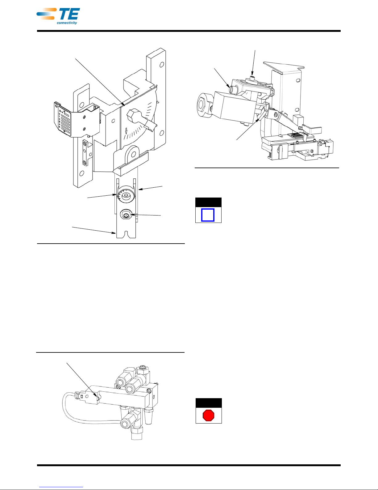
4. Loosen the crimper bolt (Figure 7).
5. Rotate the crimp height adjustment wheel
(Figure 7) one position. If a smaller crimp height is
required, decrease the number on the adjustment
whe
el. If a bigger crimp height is desired, increase
the number on the adjustment wheel.
making the crimp height
this adjustment
The crimp height range is from 1 to 7, with the smallest
crim
p height on the "1" setting.
There is an optional adjustment wheel (for
purchase) containing settings from 8 through 1
This adjustment wheel is for the crimp heights
above .125 in.
1.
5.1. Crimp Height Adjustments
Make several test cycles and inspect terminations
CLOSELY.
•Look for rough or sharp edges around crimped
barrels (flash), deformed crimps, bent terminals, or
other defects caused by worn or broken tooling. If
necessary, replace tooling as described in Section
6, REPAIR AND REPLACEMENT OF PARTS.
•If terminations appear normal, measure crimp
height of each termination as described in
408-7424, packaged with the applicator. Crimp
h
eight must agree with measurement specified on
parts list for wire size being used. Record crimp
height dimensions for reference.
•If crimp height is INCORRECT then a crimp height
adjustment is necessary. This is accomplished with
the following procedure.
If necessary, make minor or major crimp height
adjustment
s as follows.
Do not move the adjustment feature more then one
position or tooling damage may result.
6. Apply upward pressure to the crimper so that the
top e
dge of the crimper is tight against the
adjustment wheel. Continue to apply this pressure
and secure the crimper bolt.
7. Install the wrap around guard and close the guard
do
ors.
8. Crimp additional product and inspect. If the crimp
he
ight is not correct repeat the directions in the
Paragraphs 5.1,A and 5.1,B.
5.2. Terminal Strip Feed Adjustment
Part of the Terminal Strip Feed Adjustment is made
with the pneumatic power "on." T
injury , BE SURE to exercise caution around moving
machine parts with the machine "on" and the
guards open.
1. Turn electrical power off to the terminator. Keep
the p
neumatic power “on”.
2. Open the terminator guards and remove the
ap
plicator guard.
3. Raise the terminal drag. Feed in a strip of
terminals
feed hole on side feed applicators or behind the
terminal on end feed applicators.
until the feed finger drops into the first
o avoid personal
Rev A
7 of 11
Page 8
Crimp Height
Adjustment Wheel
Wire Crimper
Tool
Holder
Crimper
Bolt
Manual Precision Adjustment
Mechanism on the Terminator
Figure 7
Manual Over-Ride Button
Adjustment Locking Screw
Adjustment Screw
Stroke Clamp
NOTE
i
DANGER
STOP
4. Lower the terminal drag.
5. Depress and release the manual over-ride button
n the air feed valve located on the back of the
o
terminator until the terminal is located above the
anvil. See Figure 8.
6. Determine the direction of adjustment required to
ce
nter the terminal over the anvil.
7. Loosen the adjustment locking screw.
8. Turn the adjustment screw to make an
ad
justment. See Figure 9.
Figure 8
Rev A
408-32027
Figure 9
9. Tighten the adjustment locking screw.
For side feed applicators: Turning the adjustment
screw clockwise will move the terminal to the left
on the next feed stroke. For end
Turning the adjustment screw clockwise will move
the terminal toward the rear of the anvil on the next
feed stroke.
10. Raise the terminal drag, lif
pull the terminal strip back and repeat steps 3
through 7 until the terminal is centered over the
anvil.
11. If the feed finger stroke is incorrect, loosen the
st
roke clamp (Figure 9) and move the clamp closer
to the air cylinder for less str
cylinder for more stroke.
12. Tighten the clamp and check the feed.
oke and further from the
feed applicators:
t the feed finger, and
5.3. Strip Guide Plate and Feed Pawl Adjustments (Side-
Feed Through-Splice Applicators Only)
This procedure moves the plate on which the strip
guides are mounted. Since the terminal strip is fed into
the applicator between the strip guides, it is moved
front and back over the anvil as the strip guides are
moved.
The adjustment of the feed pawl to match any change
in the
position of the front strip guide is also described
here.
To avoid personal injury, be SURE power to the
terminator is turned "off" and the power cord is
disconnected before removing the applicato
1. With the power to the terminator "of
power cord disconnected, open the terminator
f," and the
r.
8 of 11
Page 9
408-32027
NOTE
i
NOTE
i
DANGER
STOP
NOTE
i
NOTE
i
DANGER
STOP
NOTE
i
DANGER
STOP
guard doors and remove the applicator as
described in Paragraph 3.2.
2. From bottom side of strip guide plate, loosen the
screw that holds the strip guide adjustment block to
the strip guide plate.
3. With the LEAD terminal centered over anvil, lift
a
nd hold (or block) the feed pawl up to clear the
front strip guide.
4. Turn strip guide plate adjustment screw
CLOCKWISE to
REAR, or COUNTERCLOCKWISE to move it
TOWARD FRONT. The insulation barrel of the lead
terminal should be as close as possible to the
floating shear.
5. Tighten screw to hold st r
6. Loosen screw holding feed pawl to feed finger
eed pawl holder). Move feed pawl until its tip drops
(f
into slot in front strip guide. Retighten screw.
7. Hand-cycle terminating unit, checking for proper
ter
minal feed and strip guide plate alignment.
Refer to customer manual 409-10204 for handcycling instructions.
move strip guide plate TOWARD
ip guide plate in position.
5.4. Strip Guide Adjustment
This adjustment is not used very often, because it is
only needed when the rear strip guide is not parall el to
the strip guide plate, the strip guides are not parallel to
each other, or there is a variation in strip width.
The strip guides are correctly positioned on the
strip guide plate when the applicator is built, and
normally do NOT need adjustment. DO NOT use
this procedure for front-to-rear positioning of strip refer to Paragraph 5.4, Strip Guide Plate and Feed
Pawl Adjustments.
To avoid personal injury, be SURE power to the
terminator is turned "off" and the power cord is
disconnected before making adju
guard doors open.
1. With the power to the terminator "off," and the
p
ower cord disconnected, open the terminator
guard doors.
2. Lift and hold (or block) the feed pawl up to clear
the
front strip guide, and loosen screws holding strip
guides to strip guide plate.
3. Move the rear strip guide in the desired direction,
making sure it is p
then retighten the holding screws.
4. Align the front strip guide with the holes in the
te
rminal carrier strip, but be sure the strip guides
are parallel, and that the terminal strip can move
freely with a minimum of side clearance. Retighten
the screws.
arallel to the strip guide plate, and
stments with the
If feed pawl is not aligned with the front strip guide,
refer to Paragraph 5.3, Step 4.
5. Hand-cycle terminating unit, checking for proper
ter
minal feed and strip guide alignments.
5.5. Adjustment of Shear(s) and Shear Holder(s) (Side-
Feed Through-Splice Applicators Only)
With lead terminal centered over anvil, check to see if
floating shear(s) cuts the terminal from the carrier
strip(s) correctly. If necessary, make the following
adjustments.
The lower portion of the applicator must be
removed from the terminating unit for this
procedure. See removal procedure under
Parag
raph 3.2.
A. Front Shear Adjustment
To avoid personal injury, be SURE power to the
terminator is turned "off" and the power cord is
disconnected before removing the applicato
1. With the power to the terminator "of
power cord disconnected, open the terminator
guard doors and remove the applicator as
described in Paragraph 3.2.
2. From the bottom of the base plate, loosen the two
sc
rews that secure the shear holder to the base
plate.
3. Move the shear holder and floating shear in the
de
sired direction, and retighten the screws.
There should be minimal clearance (.002 in.)
between the floating shear and the anvil; the shear
must move up and down freely
square to the back of the anvil.
4. Reinstall and re-align the applicator base plate to
the ter
minator base and load it with product so that
a terminal is centered over the anvil. Check that the
floating shear correctly cuts the terminal from the
carrier strip. If shearing action is not correct, repeat
Step s 1 and 2 or check for worn or dama ged tooling.
f," and the
, and must be
r.
B. Rear Shear Adjustment (Dual Carrier Strip Product Only)
The rear shear is more likely to need adjustment
because it is affected by differences in terminal strip
widths and strip guide plate adjustments .
To avoid personal injury, be SURE power to the
terminator is turned "off" and the power cord is
disconnected before removing the applicato
1. With the power to the terminator "of
power cord disconnected, open the terminator
guard doors and remove the applicator as
described in Paragraph 3.2.
f," and the
r.
Rev A
9 of 11
Page 10
408-32027
NOTE
i
DANGER
STOP
NOTE
i
NOTE
i
DANGER
STOP
DANGER
STOP
2. From the bottom of the base plate, loosen two
screws that hold the rear shear holder to the base
plate.
3. With the terminal strip inserted into applicator,
and the lead terminal centered over the anvil, move
the rear shear holder in the direction required to
obtain the proper cutoff tab.
4. Check that the shear is square to the end of the
te
rminal, and then tighten the holding screws.
5. Depress the floating shear and check for proper
she
aring action and proper cutoff tab.
6. If necessary, repeat Steps 2 through 5 or check
for
worn or damaged tooling.
6. REPAIR AND REPLACEMENT OF PARTS
These procedures cover the applicator parts which
most often need repair or replacement because of
wear. Remove the a pplicato r from th e ma chine be fo re
doing any maintenance work. Refer to the exploded
view drawing and parts list packaged with the
applicator for identification of parts. Be sure to order
replacements for parts used from sp are parts stock, so
that they will be available when needed.
Wipe parts with a clean, dry cloth as they are
removed from the applicator. Then, when putting
them
back into applicator, wipe mating surfaces
with your fingers to make sure that all lint and other
foreign matter have been removed.
6.1. Anvil Replacement
To avoid personal injury, be SURE power to the
terminator is turned "off" and the power cord is
disconnected before removing the app
1. With the power to the terminator "off," and the
p
ower cord disconnected, open the terminator
guard doors and remove the applicator as
described in Paragraph 3.2.
2. Raise the terminal drag, raise feed pawl, and pull
str
ip back so lead terminal is between strip guides.
3. From bottom of base plate, remove screw that
h
olds anvil to base plate.
4. Remove anvil from groove in top of base plate.
5. Install anvil using reversed procedure. If a new
a
nvil is needed, be sure the part n umber o f the new
anvil agrees with the number on the applicator p arts
list.
When the anvil is replaced, the front shear and
holder must be re-aligned. See Paragraph 5.6,A.
licator.
6.2. Floating Shear Replacement (Side-Feed Through-Splice
Applicators Only)
It is not necessary to remove shear holder(s) to
replace floating shear(s). Before removing floating
shear(s), note orientation fo
floating shears are spring-loaded, so be careful
during removal.
To avoid personal injury, be SURE power to the
terminator is turned "off" and the power cord is
disconnected before removing the applicato
1. With the power to the terminator "of
power cord disconnected, open the terminator
guard doors and remove the applicator as
described in Paragraph 3.2.
2. Raise the terminal drag , raise feed pawl, and pull
st
rip back so lead terminal is between strip guides.
3. Push down on the floating shear, then remove
sh
ear retaining screw from side of shear holder.
4. Slowly release pressure on floating shear.
Compres
5. After removing floating shear, lift compression
spr
6. Inspect spring for damage and replace it if
necess
7. Re-install floating shear(s) using reversed
procedure.
number agrees with the number on the parts list.
8. Raise feed pawl and move lead terminal over the
an
9. Check shear holder adjustment as described in
Par
Holder(s).
sion spring will push it out of shear holder.
ing out of shear holder.
ary. Refer to parts list for correct number.
If installing new shear, be sure part
vil. Lower thew terminal drag to lower stock drag.
agraph 5.6, Adjustment of Shear(s) and Shear
r re-installation. The
r.
f," and the
6.3. Crimper Replacement
To avoid personal injury, be sure power to the
machine is turned "off" and the power cord is
disconnected BEFORE
the machine. The machine ram should be in the
raised position.
1. Turn off th e terminator and disconnect power.
2. Open the guard doors to gain access to the
ap
plicator.
3. Remove crimper bolt that holds the front shear
de
pressor, front shear depressor spacer, tubular
spacer, insulation crimper, crimper spacer, and wire
crimper in place on the ram assembly. Note position
of of parts for purposes of re-installation.
4. Replace parts.
taking the applicator out of
6. Re-align crimpers.
Rev A
5. Re-install parts in reversed order of removal.
10 of 11
Page 11
NOTE
i
408-32027
NOTE
i
DANGER
STOP
DANGER
STOP
NOTE
i
CAUTION
!
DANGER
STOP
CAUTION
!
The upper end of the wire crimper must be up
against the adjustment wheel on the tool holder.
6. Tighten the crimper bolt ONLY finger tight.
Insulation crimpers with legs of equal length, that
are identical front and back, may
either side out. All other insulation crimpers MUST
be positioned with part number facing the direction
noted during removal. If new parts are used, be
SURE part numbers agree with numbers on parts
list.
7. Lift feed pawl and pull te
lead terminal is between strip guides.
8. Form a piece of heavy paper over anvil, then
slowly hand-c
alignment of crimpers with anvil. When ram
assembly has reached bottom of stroke, carefully
tighten crimper bolt. Crimpers MUST move freely
over anvil after paper is removed.
ycle machine while watching
rminal strip back until
be positioned with
6.4. Feed Pawl Replacement
To avoid personal injury, be SURE power to the
terminator is turned "off" and the power cord is
disconnected before making repla
guard doors open.
1. With the power to the terminator "off," and the
p
ower cord disconnected, open the terminator
guard doors.
2. Remove the adjustment screw which holds the
fe
ed pawl to the feed finger (feed pawl holder).
3. Replace feed pawl using reversed procedure. If
new p
awl is installed, be SURE the part number
agrees with the number on the parts list.
4. Adjust feed pawl as described in Paragraph 5.4.
cements with the
7. CLEANING AND LUBRICATION
For best performance and minimum downtime,
applicator should be cleaned, inspected, and
lubricated after each eight hours of operation, and
each time it is removed from machine to be placed in
storage.
7.1. Cleaning
To avoid personal injury, be SURE power to the
terminator is turned "off" and the power cord is
disconnected before removing the app
licator.
2. Using a clean, dry cloth, remove dirt, chips, etc.,
fro
m applicator. The entire applicator may be
immersed in a suitable commercial solvent (one that
won't affect paint or plastic) once a month to flush
out chips.
3. Lubricate applicator as described in Paragraph
7.2 b
efore re-assembling.
7.2. Lubrication
Lubricate applicator each eight hours at the following
points with SAE 20 motor oil (nondetergent), or where
specified, light grease.
DON'T use too much oil or grease on applicator.
Any excess lubricant MUST be wiped of
placing applicator back in service. Don't put
lubricants between wire and insulation discs.
To avoid personal injury, be SURE power to the
terminator is turned "off" and the power cord is
disconnected before removing the applicato
1. With the power to the terminator "of
power cord disconnected, open the terminator
guard doors and remove the applicator as
described in Paragraph 3.2.
2. Carefully lay applicator on its side and put one
dr
op of oil on feed finger pin. Wipe feed finger pin to
remove excess oil.
3. Put a drop or two of oil on the floating shear(s) in
th
e shear holder(s).
f before
r.
f," and the
8. APPLICATOR STORAGE
When storing applicator, or taking it out of machine
for any reason, be sure to avoid damage to the
toolin
g by preventing the bottoming of the upper
tooling on the applicator base.
1. Remove the terminal strip as described in
Par
agraph 4.2.
2. Remove the applicator as described in Paragraph
3.2.
3. Clean and lubricate the applicator as described in
Section 7, CLEANING AND LUBRIC
4. Store the a pplicator in an area where it cannot be
d
amaged.
ATION.
1. With the power to the terminator "off," and the
p
ower cord disconnected, open the terminator
guard doors and remove the applicator as
described in Paragraph 3.2.
It is NOT necessary to remove section of terminal
strip to clean applicator.
Rev A
9. REVISION SUMMARY
This document supersedes 408-127000. New release
of 408-32027.
11 of 11
 Loading...