

Page 1

Customer Manual
© 2017 TE Connectivity Ltd. family of companies.
All Rights Reserved.
*Trademark
TE Connectivity, TE connectivity (logo), and TE (logo) are trademarks. Other logos, product, and/or company names may be trademarks of their respective owners.
PRODUCT INFORMATION 1-800-522-6752
This controlled document is subject to change.
For latest revision and Regional Customer Service,
visit our website at www.te.com.
C-Head Adapter Battery Powered
Crimp Tool Kit; PN 2844990-[ ]
ORIGINAL INSTRUCTIONS
409-35003
21 JUN 17 Rev B
SAFETY PRECAUTIONS — READ THIS FIRST! ..................................................................... 2
SAFETY PRECAUTIONS — AVOID INJURY — READ THIS FIRST! ...................................... 3
1. INTRODUCTION .................................................................................................................. 4
2. RECEIVING AND INSPECTION .......................................................................................... 5
3. USER INTERFACE INFORMATION (PRE-OPERATION TESTING) .................................. 5
3.1.LED Indicators ................................................................................................................ 5
3.2.Pressure Sensor ............................................................................................................ 5
4. DIE INSTALLATION AND REMOVAL ................................................................................. 6
4.1.Die Set Installation (Figure 5) ......................................................................................... 6
4.2.Die Set Removal ............................................................................................................ 6
5. OPERATION ........................................................................................................................ 7
5.1.Battery Installation and Removal ................................................................................... 7
5.2.Crimping ......................................................................................................................... 7
6. PREVENTIVE MAINTENANCE ........................................................................................... 7
6.1.Daily Maintenance .......................................................................................................... 7
6.2.Yearly Maintenance ....................................................................................................... 7
6.3.Lubrication ...................................................................................................................... 8
7. TROUBLESHOOTING ......................................................................................................... 8
8. REPLACEMENT AND REPAIR ........................................................................................... 8
9. DECOMMISSIONING ........................................................................................................... 9
10. RESTRICTION ON HAZARDOUS SUBSTANCES (RoHS) INFORMATION ...................... 9
11. REVISION SUMMARY ......................................................................................................... 9
1 of 9
Page 2
2 of 9
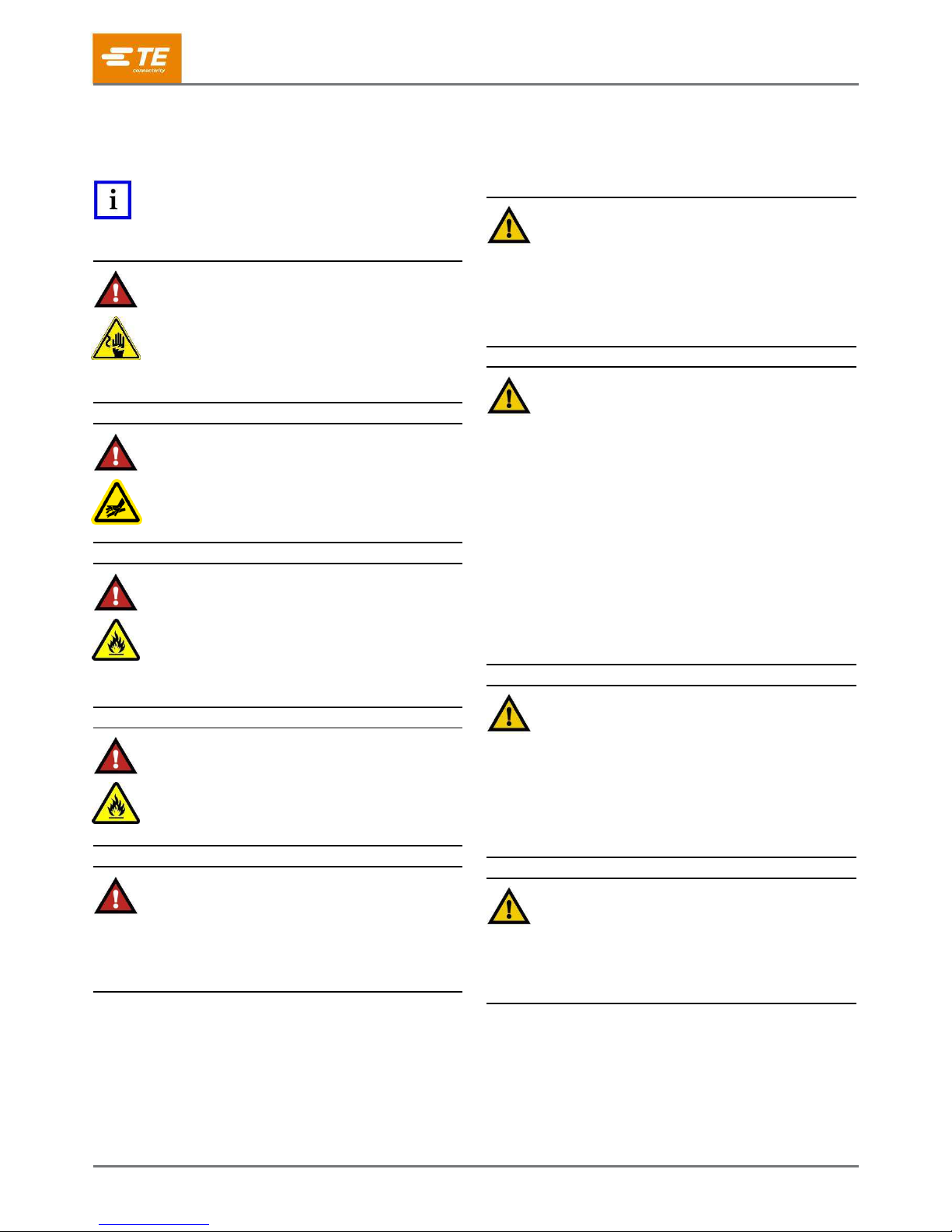
SAFETY PRECAUTIONS — READ THIS FIRST!
IMPORTANT SAFETY INFORMATION
409-35003
NOTE
Keep all decals clean and legible, and replace them
when necessary.
DANGER
ELECTRIC SHOCK HAZARD
This tool is not insulated. When using this unit near
energized electrical lines, use proper personal protective
equipment.
Failure to observe this warning could result in severe
injury or death.
DANGER
SKIN INJECTION HAZARD
Do not use hands to check for oil leaks. Highly
pressurized oil will puncture the skin causing serious
injury, gangrene, or death. If injured, seek medical help
immediately to remove the oil.
DANGER
FIRE HAZARD
Do not use solvents or flammable liquids to clean the
crimping tool. Solvents or flammable liquids could ignite
and cause serious injury or property damage.
Failure to heed these warnings could result in severe
injury from harmful fumes or burns from flying debris.
DANGER
FIRE HAZARD
Do not dispose of batteries in a fire. They will vent
fumes and will explode. Instead, dispose of batteries in
an environmentally responsible manner or send the
battery back to TE.
DANGER
Inspect the tool and jaws/dies before each use. Replace
any worn or damaged parts. A damaged or improperly
assembled tool can break and strike nearby personnel.
Failure to observe this warning could result in severe
injury or death.
CAUTION
— Do not place the tool in a vise. The crimping tool is
designed for hand-held operation.
— Protect the crimping tool from rain and moisture.
Water will damage the crimping tool and battery.
Failure to observe these precautions may result in injury
or property damage.
CAUTION
— Do not allow anything to contact the battery
terminals.
— Do not immerse the batteries in liquid. Liquid may
create a short circuit and damage the battery. If the
batteries are immersed, contact your service center for
proper handling.
— Do not place the battery into a pocket, tool pouch, or
tool box with conductive objects. Conductive objects
may create a short circuit and damage the battery.
— Do not place a battery on moist ground or grass.
Moisture may create a short circuit and damage the
battery.
Failure to observe these precautions may result in injury
or property damage.
CAUTION
— Do not store the battery at more than 60°C [140°F].
Damage to the battery can result.
— Do not use another manufacturer’s charger.
— Do not attempt to open the battery. It contains no
user-serviceable parts.
Failure to observe these precautions may result in injury
or property damage.
CAUTION
— Do not perform any service or maintenance other
than as described in this manual. Injury or damage to
the tool may result.
Failure to observe these precautions may result in injury
or property damage.
Rev B
Page 3

409-35003
3 of 9
SAFETY PRECAUTIONS — AVOID INJURY — READ THIS FIRST!
Safeguards are designed into this application equipment to protect operators and maintenance personnel from
most hazards during equipment operation. However, certain safety precautions must be taken by the operator
and repair personnel to avoid personal injury, as well as damage to the equipment. For best results, application
equipment must be operated in a dry, dust-free environment. Do not operate equipment in a gaseous or
hazardous environment.
Carefully observe the following safety precautions before and during operation of the equipment:
Always wear approved eye protection while operating
equipment.
Always wear appropriate ear protection while using
equipment.
Moving parts can crush and cut. Always keep guard(s)
in place during normal operation.
Electrical shock hazard.
Always turn off the main power switch and disconnect
the electrical cord from the power source when
performing repair or maintenance on the equipment.
Never insert hands into installed equipment.
Never wear loose clothing or jewelry that may catch in
moving parts of the equipment.
Never alter, modify, or misuse the equipment.
SUPPORT CENTER
CALL TOLL FREE 1-800-522-6752 (CONTINENTAL UNITED STATES AND PUERTO RICO ONLY)
The Support Center offers a means of providing technical assistance when required. In addition, Field Service
Specialists are available to provide assistance in the adjustment or repair of the application equipment when
problems arise which your maintenance personnel are unable to correct.
INFORMATION REQUIRED WHEN CONTACTING THE SUPPORT CENTER
When calling the Support Center regarding service to equipment, it is suggested that a person familiar with the
device be present with a copy of the manual (and drawings) to receive instructions. Many difficulties can be
avoided in this manner.
When calling the Support Center, be ready with the following information:
1. Customer name
2. Customer address
3. Person to contact (name, title, telephone number, and extension)
4. Person calling
5. Equipment number (and serial number if applicable)
6. Product part number (and serial number if applicable)
7. Urgency of request
8. Nature of problem
9. Description of inoperative component(s)
10. Additional information/comments that may be helpful
Rev B
Page 4

409-35003
4 of 9
Length
387.4 mm [15.25 in.]
Width
72.9 mm [2.87 in.]
Depth
114 mm [4.5 in.]
Mass/Weight (with Battery)
1.75 kg [3.85 lbs]
Sound Level
70 dBA at 1 meter
Vibration
< 2.5 m/s2
Hydraulic Oil
Shell Tellus T15 or RIVOLTA S.B.H. 11
Maximum Crimping Force
15.6 kN [1.75 tons]
Average Crimping Time
2-4 seconds
Average Crimps Per Charge
85-170 (Approx.)
Charging Voltage
18V
Charging Time
15 Min.—1.3 Ah/22 Min.—3.0 Ah
Crimping Tool Kit
Region Of Use
Battery Charger
Battery Charger Voltage
Ram Retract Switch
2844990-1
North America
2217331-1
110V
Yes
2844990-2
Europe
2217331-2
220V
C-Head Die Sets For Use with
Battery Powered Crimping Tool
Instruction Sheet
47808-5
408-1632
47808-6
90145-1
408-7175
47811
408-9641
576711
408-10039
576716
576720
Crimping Tool Kit with Battery Cartridge Installed
C-Head Adapter
Release Switch
Light-Emitting Diode
(LED) Indicator Light
Battery Lock
Trigger
Battery Cartridge 2217332-1
Shell, Tellus, and RIVOLTA are trademarks of their respective owners.
Figure 1
1. INTRODUCTION
Lithium-ion battery-powered crimping tool kit 2844990-[ ] consists of a battery crimping tool with a C-Head
Adapter installed, as well as two rechargeable battery cartridges used to power the tool. See Figure 1.
Each kit has a battery charger. The battery charger part number, its voltage, and the kit region of use are listed
in Figure 2. The battery-powered crimping tool may have a release switch to retract the ram.
Figure 2
Each kit is designed to adapt the crimping head from any C-Head listed in Figure 3 for use with the battery
powered crimping tool. For crimping head information (including wire preparation, crimping, maintenance and
inspection, and replacement procedure) refer to the appropriate instruction sheet for the associated hand tool.
Rev B
Figure 3
Page 5

409-35003
5 of 9
WHAT HAPPENS
WHAT IT MEANS
Red LED flashes for two seconds
The battery has been inserted in the tool
Red LED is lit constantly for 20 seconds at the end of the cycle
Battery charge is below 17 volts at the beginning of the cycle
Tool will not start. Red LED remains lit for 20 seconds after trigger is released
Battery charge is below 16 volts at the beginning of the cycle
Tool will stop. Red LED remains lit for 20 seconds after the trigger is released
Battery voltage drops below 13 volts during the cycle
Tool will stop. The LED will flash for 20 seconds after the trigger is released
Motor current exceeds 20A during the cycle
Circuit has become hot
When reading this manual, pay close attention to DANGER, CAUTION, and NOTE statements.
DANGER
Denotes an imminent hazard that my result in moderate or severe injury.
CAUTION
Denotes a condition that may result in product or equipment damage.
NOTE
Highlights special or important information.
NOTE
Dimensions in this customer manual are in metric units [with customary units in brackets]. Figures and illustrations are for
reference only and are not drawn to scale.
2. RECEIVING AND INSPECTION
Each kit is thoroughly inspected during and after assembly. Prior to packaging and shipping a final series of
tests and inspections is made to ensure proper function of the tool. The following inspection should be
performed as a safeguard against potential problems generated in transit.
In a well-lighted area, carefully uncrate the tool kit and inspect each component as it is removed from
the crate.
Thoroughly inspect each component for evidence of damage that may occurred in transit. If any of the
components are damaged, file a claim against the carrier and notify TE immediately.
Keep this manual and all drawings and product samples with the tool for the benefit of operation and
maintenance personnel.
The crimping tool should be inspected at regularly scheduled intervals, depending on care, degree of operator
skill, the type and size of the product to be crimped, and environmental conditions. At a minimum, the tool
should be inspected after every 40 hours of use.
3. USER INTERFACE INFORMATION (PRE-OPERATION TESTING)
3.1. LED Indicators
White LED Work Light
The LED automatically turns on when the trigger is pulled. The indicator remains lit for ten seconds after
the trigger is released.
Red LED Indicator
The tool is equipped with a special circuit board incorporating several important features. These features
inform the user of the current status of the tool. The red LED signals in the cases given in Figure 4.
Figure 4
3.2. Pressure Sensor
The tool is equipped with a pressure sensor that alerts the user of an incomplete crimp:
If the tool is manually retracted before completion of a crimp, the red LED will flash for two seconds
and an audible alarm will sound for two seconds.
If the tool is unable to reach the required crimp force, the red LED will flash for two seconds and an
audible alarm will sound until after the trigger is released.
NOTE
The tool has an on-board memory of previous crimp cycles and the cycle count. This information can be accessed and
downloaded onto a computer using USB adapter module 2217896-1.
Rev B
Page 6

409-35003
6 of 9
Typical Dies
4. DIE INSTALLATION AND REMOVAL
CAUTION
Do not operate the tool without the C-Head Adapter installed - damage to the ram or seals can result.
CAUTION
Do not operate the tool without a die set installed. Damage to the adapter can result.
C-Head Adapter Battery Powered Crimp Tool Kit 2844990-[ ] comes with the C-Head already installed on the
Battery-powered hand tool. The only installation required is the installation of the dies.
DANGER
To avoid personal injury, be sure to exercise extreme caution when handling the crimp tool. Remove the battery before
installing or removing the dies.
4.1. Die Set Installation (Figure 5)
If dies to be installed in the tool require insulation adjustment, refer to the instruction sheet packaged with the
dies for adjustment, then proceed as follows:
Each set of dies consists of a moving die and a stationary die. Most moving dies have square corners and the
stationary dies have chamfered corners. Exceptions to this feature will be shown on instruction sheets covering
the use of the particular dies.
1. Remove the battery from the tool.
2. Position the stationary die in the stationary die holder. Turn the die retaining screw sufficiently to hold
the die in place. Do not tighten the screw.
3. Position the moving die in the moving die holder. Turn the die retaining screw sufficiently to hold the
die in place. Do not tighten the screw.
Figure 5
4. Replace the battery and check the alignment by pulsing the trigger to (slowly) close the dies, making
sure the anvil and indenter are properly aligned.
5. With the dies closed, tighten the die retaining screws.
4.2. Die Set Removal
To remove or change the dies, simply loosen the die retaining screws and remove the dies.
Rev B
Page 7

409-35003
7 of 9
5. OPERATION
5.1. Battery Installation and Removal
NOTE
Batteries Directive 2006/66/EC introduces new requirements from September 2008 on removability of batteries from waste
equipment in EU Member States. To comply with this Directive, this device is designed to allow the rechargeable battery pack
to be easily removed by the end-user when it needs to be replaced.
To install the battery, slide the battery into the bottom of the crimping tool until it can go no further. There will be
an audible “click” of the battery lock to indicate that the battery has been properly installed.
To remove the battery, disengage the battery lock by applying pressure on the lock toward the bottom of the
crimping tool, and slide the battery away from the tool.
DANGER
Always dispose of the old battery pack in an environmentally-responsible way; in accordance with local waste regulations.
Where possible, recycle the battery cartridge. Contact local authority for details of battery recycling locations.
5.2. Crimping
The following procedure provides only general information concerning crimping. Refer to the instructions
packaged with the dies for detailed information including wire stripping dimensions and instructions for
positioning terminals in the crimping head.
DANGER
To avoid personal injury, keep fingers clear of the crimping area.
To operate the C-Head Adapter Battery Powered Crimp Tool PN 2844990-[ ]:
1. Insert the terminal into the dies.
2. Depress the trigger to advance the moving jaw in order to hold the terminal in place. DO NOT deform
the terminal body.
3. Place a pre-stripped wire into the barrel of the terminal.
4. Depress and hold the trigger to complete the crimp.
The crimp tool returns automatically to the first position of its cycle when the crimp is complete.
NOTE
If it is necessary to retract the ram before a crimping cycle is completed, push the release switch. This will result in the
complete retraction of the ram.
CAUTION
This tool is not designed for continuous operation. After 100 cycles, allow the crimp tool to cool for 15 minutes.
6. PREVENTIVE MAINTENANCE
6.1. Daily Maintenance
Perform the following maintenance on a daily basis.
1. Inspect the crimping head jaws for wear or damage such as cracks, gouges, or chips.
2. Inspect the tool for damage or leaks. If damage is detected, return the tool to TE for repair.
3. Clean the tool, removing accumulations of dirt and grease from the crimping head, particularly in
areas where the crimping head is installed and the product is crimped. Wipe the entire tool frequently
with a clean, lint-free cloth.
6.2. Yearly Maintenance
Once per year or every 10,000 cycles (whichever comes first), the adapter should be returned to TE for
inspection.
Rev B
Page 8

8 of 9
6.3. Lubrication
Problem
Probable Cause
Remedy
Tool is
inoperative
Dirt contaminants, etc., in ram area of tool
Return tool to TE for evaluation
Crimping tool battery contacts damaged
Reform the contacts
Tool components are worn or damaged
Return tool to TE for evaluation
Jaws stop
during operation
Oil level is low
Return tool to TE for evaluation
Air in the hydraulic system
Pull trigger and hold retract button simultaneously. Hold for
approximately ten seconds
Tool loses oil
Damaged internal seal
Return tool to TE for evaluation
Part Number
Description
2217332-1
Battery
2217331-1
120V Charger, North America
2217331-2
220V Charger, Europe
Molykote is a trademark.
1. Lubricate all pins, pivot points, and bearing surfaces with a high-quality grease. TE recommends using
Molykote paste, which is a commercially available lubricant.
2. Lubricate the tool according to the following schedule:
Adapter used in daily production should be lubricated daily
Adapter used occasionally in daily production should be lubricated weekly
Adapter used weekly should be lubricated monthly
7. TROUBLESHOOTING
Before beginning a troubleshooting procedure, verify that the battery is operational.
1. Ensure the battery is charged. Re-check the battery after several minutes to ensure the battery is
holding its charge.
2. Use a non-flammable contact cleaner or pencil eraser to clean the electrical contacts on the battery
and crimping tool.
3. Re-install the battery, and check the crimping tool again.
Refer to Figure 6 for problems, probable causes, and remedy.
409-35003
Figure 6
8. REPLACEMENT AND REPAIR
DANGER
To avoid personal injury, always remove the battery cartridge from the tool before performing any maintenance on the
crimping tool.
Replacement parts are identified in Figure 7. The recommended spares should be stocked for immediate
replacement. Order replacement parts (or return parts) through your TE Representative, or call
1-800-522-6752, or send a facsimile of your purchase order to 717-986-7605. Or write to:
CUSTOMER SERVICE (038-035)
TE CONNECTIVITY CORPORATION
PO BOX 3608
HARRISBURG, PA 17105-3608
Call 1-800-522-6752 for customer repair service. For replacement parts for the crimping head, refer to the
instruction sheet packaged with the specific crimping head.
Figure 7
Rev B
Page 9

409-35003
9 of 9
9. DECOMMISSIONING
In compliance with the regulations in force in the country where the tool is used, the user must make sure that
waste produced during operation is correctly disposed. Disposal of lubricants and parts removed must be
carried out in compliance with the standards in force in the country where the tool is used.
10. RESTRICTION ON HAZARDOUS SUBSTANCES (RoHS) INFORMATION
Information on the presence and location of any substances subject to RoHS can be found at
http://www.te.com/usa-en/utilities/product-compliance.html
1. Click “Check Product Compliance and Get Statements of Compliance (SoC)”
2. Enter part number and click “Search”
11. REVISION SUMMARY
Added Figure 3 (C-Head Die Sets For Use with Battery Powered Crimping Tool and associated 408
Series Instruction Sheet) and explanatory paragraph immediately before
Renumbered all succeeding figures and revised applicable references throughout
Rev B
 Loading...