

Page 1

Technical equipment of TC600 PLC
Contents
1. Abbreviations and Terms ...................................................................................................... 3
2. Description............................................................................................................................. 5
2.1 The Specification................................................................................................................. 5
2.2 Compatibility ........................................................................................................................ 5
2.3 Communication.................................................................................................................... 5
2.4 Di str ibuted Control ............................................................................................................... 5
2.5 The Building......................................................................................................................... 6
2.6 Design..................................................................................................................................7
3. Parameters Overview ............................................................................................................. 8
3.1 Basic P r oper ties................................................................................................................... 8
3.2 Oper ational Conditions......................................................................................................... 9
3.3 Basic Parameters.................................................................................................................9
4. Central Unit............................................................................................................................10
4.1 Basic P ar ts and Parameters................................................................................................10
4.2 User Accessible Memories..................................................................................................10
4.3 Analog Outputs...................................................................................................................12
4.4 Serial Com municat ion Channels .........................................................................................13
4.4.1 Serial Communication Channel 1 (CH1).......................................................................13
4.4.2 Serial Communication Channel 2 (CH2).......................................................................16
4.4.3 Serial Communication Channel 3 (CH3).......................................................................16
4.5 Setting of CPU Parameters.................................................................................................17
4.5.1 Setting of Parameters of Ser ial Com municat ion Channels CH1, CH2, CH3..................17
4.5.2 Management of the user program source mem or y .......................................................20
5. Input and Output Unit...........................................................................................................21
5.1 Basic Functions...................................................................................................................21
5.1.1 Binary Inputs................................................................................................................21
5.1.2 Binary Transistor Outputs.............................................................................................22
5.1.3 Binary Relay Outputs...................................................................................................23
5.1.4 Analog Inputs of TC605, TC606, TC625, TC626 Modules ............................................24
5.1.5 Analog Inputs of the TC634 Module .............................................................................25
5.2 Special Functions................................................................................................................29
5.2.1 Interrupt Inputs.............................................................................................................29
5.2.2 Counter of Type 3 ........................................................................................................29
5.2.3 Admeasurement of Position by the I nc r emental E nc oder..............................................30
5.2.4 Measurement of the Signals Period and Phase Shift....................................................31
6. Packaging..............................................................................................................................32
7. Transport...............................................................................................................................32
8. Storage ..................................................................................................................................32
9. Installation.............................................................................................................................32
9.1 Principl es of Proper Installati on...........................................................................................32
9.2 Ensuri ng of the Requi r ed Operational Temperature.............................................................33
9.3 The M ounting......................................................................................................................34
9.4 Arr angement of Connecting of Terminal Boar ds..................................................................36
9.5 Connect ion of t he P LC Inputs and Outputs..........................................................................45
9.5.1 Connection of the Protec tive Connector .......................................................................45
9.5.2 PLC Power Supply .......................................................................................................45
9.5.3 Connection of Binary Inputs .........................................................................................46
9.5.4 Connection of Binary Transistor Outputs......................................................................47
9.5.5 Connection of Binary Relay Output s.............................................................................48
9.5.6 Connection of Analog Inputs of TC605, TC606, TC625, T C626....................................49
9.5.7 Connection of TC634 Analog Inputs.............................................................................49
9.5.8 Connection of Analog Outputs ......................................................................................51
9.5.9 Connection of the CH1 Inter face ..................................................................................52
9.5.10 Connection of the CH2 Inter face ..................................................................................54
9.5.11 Connection of the CH3 Inter face ..................................................................................56
9.5.12 Connection of Interrupt Inputs ......................................................................................56
9.5.13 Connection of the Type 3 Count er................................................................................56
9.5.14 Incremental Encoder Connection..................................................................................57
1 TXV 138 08.02
Page 2

Tecomat TC600
9.5.15 Connection of Inputs f or M easurement of the Period and Phase Shi ft ..........................57
10. Attendance ............................................................................................................................58
10.1 Instructions for Saf e A ttendance..........................................................................................58
10.2 Putting into Operation.........................................................................................................58
10.3 PLC Initialization.................................................................................................................58
10.4 Operational Modes..............................................................................................................59
10.4.1 Change of Operational Modes......................................................................................59
10.4.2 Activities Perf or med at Changing of the PLC Mode on the Standard Basis ...................59
10.4.3 Optionally Performed A c tivities at Change of the P LC M ode........................................60
10.4.4 Restarts of the User Program.......................................................................................60
10.5 P r ogr amming and Debugging of the PLC Program..............................................................61
10.5.1 Configur ation Constants in t he User Pr ogr am...............................................................62
10.5.2 Software Configuration.................................................................................................63
10.5.3 Serv icing of Binary Inputs ............................................................................................65
10.5.4 Serv i cing of Binary Outputs..........................................................................................66
10.5.5 Serv icing of Analog Inputs............................................................................................66
10.5.6 Serv i cing of Analog Outputs.........................................................................................70
10.5.7 Serv icing of Serial Channels........................................................................................70
10.5.8 Serv icing of Interrupt Inputs .........................................................................................71
10.5.9 Serv icing of the Type 3 Count er...................................................................................76
10.5.10 Incremental Encoder Servic ing.................................................................................79
10.5.11 Measurement of the Signal P er iod and Phase Shift ..................................................81
10.5.12 Physical Addresses of Inputs and Outputs ................................................................84
10.6 Testing of Input and Output S ignals ....................................................................................84
10.7 Instruction Set.....................................................................................................................85
11. Diagnostics and Removal of Faults.....................................................................................86
11.1 Conditions for Proper Function of the Diagnostics...............................................................86
11.2 Indication of Errors..............................................................................................................86
11.3 Serious Errors.....................................................................................................................86
11.3.1 User Program Errors....................................................................................................87
11.3.2 Errors in the Peripheral System....................................................................................89
11.4 Other Errors........................................................................................................................90
11.4.1 Errors of Serial Communication....................................................................................91
11.4.2 System Errors..............................................................................................................91
11.4.3 User Program Errors....................................................................................................92
11.4.4 Errors in the Peripheral System....................................................................................92
11.5 S olution of Communication Problems with the Superi or S y stem..........................................92
12. Removal of F aults .................................................................................................................95
13. Maintenance..........................................................................................................................95
13.1 Demounting of the PLC Par ts..............................................................................................95
13.2 Chec k ing of PE Connec tors Interconnect ion........................................................................95
13.3 Chec k ing of t he P ower Supply.............................................................................................95
13.4 Chec k ing of Voltage of B inary Inputs...................................................................................95
13.5 Chec k ing of Voltage of B inary Transistor Outputs ...............................................................96
13.6 B attery Exchange................................................................................................................96
13.7 Fuse Exchange...................................................................................................................96
13.8 Cleaning..............................................................................................................................96
14. The G uarantee.......................................................................................................................96
TXV 138 08.02 2
Page 3

Technical equipment of TC600 PLC
Introduction
The manual
provides information necessary for proper application, operation and
lers
maint enance of basic m odules of programm able logic cont rollers Tecomat
TC601 to TC607, ex tension modules TC621 to TC626 and half extension
modules TC631 to TC634. It describes possibilities of the building, differences in technical equipment of individual types, technical parameters of
electronic circuits, control and diagnostics and it determines requirements
for tr ansportati on, storage and i nstall at ion of the system . Out of data necessary for programming, the m anual contains only description of the way of
declaration of individual types in an integrated development environment
and servicing of inputs and outputs. The very description of the development environment for programming of Tecomat programmable logic controll ers is a part of the dev elopment env ironm ent. The princi ple of the programmable logic controller function, programming principles and the
instructi on file of Tecomat programmabl e logic control lers are described in
detail i n the
and
Instruction set of the Tecomat PLC, TXV 001 05.02
tion of m odes of serial communication channels is giv en in the handbook
Serial c omm unicat ion of Tecom at program m able logi c contr oller s, TXV 001
06.02.
Wi th regard to high inheritance of properties of indivi dual types of this
series, maj ority of data i s given together f or the whole series. Parameters
are given indivi dually i n the case that param eters of a series type differ.
Technical equipment of TC600 programm able logic control-
Handbook of the Tecomat PLC programmer, TXV 001 09.02
. Detail ed descrip-
1. Abbreviations and Terms
PLC Programmable Logic Controller
CPU PLC Central Processor Unit
CH1, CH2, CH3 PLC Serial Channels
RTC circuit Real Tim e Clock, c ircuit for generation of real time
Tecomat registered trademark of PLC Teco a. s.
Tecomat TC600 marki ng of PLC of the TC600 series
(TC601-TC607, TC621-TC626, TC631- TC634)
Tecoreg registered trademark of Teco a. s. regulators
Programmable Logic Controller ( P LC)
freely distributable programmable system designed for
logic cont rol of work machines, technologi cal processes,
etc.
Basic Module (BM)
smallest fully functional set of the PLC
Extension Module (EM, EM/2)
module designed f or extension of functi onal possibilities
of the PLC basi c module by additional inputs and outputs
RAM Memory Random Access Memory, memory type f or reading and
writing
EEPROM MemoryElectrically Erasable and Programmable Read Only
Memory, memory type for r eading
User Program Memory
part of the PLC RAM memory assigned f or storage of the
user program, dat a and tables
User Program Sourc e M emory
power independent PLC memory desi gned for storage of
the source (backup) user program, data and tables
User Process
part of the user algorithm assembled by the user from
instructions of the problem ori ented language of the PLC.
Ever y user process is inclosed i n instruct ions P and E of
a comm on number (0 to 64)
3 TXV 138 08.02
Page 4

Tecomat TC600
User Program set of all user proc esses designed for c ontrol of the given
applicat ion
Multi pr ogr amming
set of rul es according to whic h indi v idual user processes
are activated
Program Cycle set of user processes which are activ ated cyclicall y ac-
cording to rules of m ultiprogr amming
Cycle Turn phase of the system pr ogr am between the last process of
the past cycle and the f irst process of the new cycle. In
the cycle turn, values of outputs are transmitted from re-
gisters Y, new values of i nputs are scanned int o regi sters
X, time data in ti mers and system regi sters are updated,
and data receiv ed by comm unication channels and new
data for transmission are t r ansferred
Cycle Int er r uption by User
updating of processes P41, P43 and P44. These proces-
ses may be activated in arbitrary position of the user
program cycle.
Initialization Processes
processes activated after turning on or restart of the
system (P62 after warm reboot , P63 aft er c old reboot)
User D Data
constants of the user program stored in memory of the
user program
User T Tables
most of ten constants of t he user progr am concentrated in
integrated sets (T tabl es). T hey are usuall y used for defi-
nition of subsystems (decoders, c ombi nation, sequenti al,
tim e or numeric subsystem s).
Configur ation Constants, K Dat a
set of data in the user program memory designed for
setting of the system configuration and modification of
the system activity. Not available to the user program,
are edited f rom within the dev elopment envi ronment. If
not edited, the system shows standard behaviour .
Scratchpad, Registers X, Y, S, R
part of the RAM memory avai lable to the user as input
images (regi sters X), output i m ages (register s Y), system
(S) and user (R) registers.
Remanent Part of the Scratchpad
part of r egisters R the contents of which i s retai ned dur-
ing warm reboot. The extent may be selected by the
configurational constant of remanent registers R. Other
registers R and registers X and Y are not remanent and
are reset in ev ery reboot or turni ng on. The user has t he
possibility to store actual output values in remanent reg-
isters R.
Warm Reboot way of activation of the system and user program in
which the contents of the scratchpad remanent part are
retained. The rest of t he scratchpad is reset.
Cold Reboot way of activation of the system and user program in
which all regi sters of the scratchpad are reset. Cold re-
boot is performed in the case that an attempt at warm
reboot has been non-successful (the system has detec-
ted damage of the stored data).
TXV 138 08.02 4
Page 5

Technical equipment of TC600 PLC
2. Description
2.1 The Specification
PLC's of the TC600 series are freely programmable logic systems designed for control of work machines and technol ogical pr ocesses in vari ous
and div erse areas of producti on. They com plement the int egrated series of
modular and compact Tecomat PLC's with a small modular system
equipped with the driv e for m ounting on a U strip.
2.2 Compatibility
Although PLC's of the TC600 series are designed f or the smal lest appli cations, use properties of lar ge Tecomat P LC's remain ret ained. Signi fi cant
property is uniformness of technical and program means for creation and
debugging of the user program and uniformness of the highly ef ficient instruction set and system services with other Tecomat PLC's allowing for
evaluation of experience gained in applications of other Tecomat systems.
2.3 Communication
Two serial com muni cation c hannels f itt ed in a standar d m anner with optional int erf ac es and possibility of addition of a thi rd c om m unic ati on channel
allow for simultaneous local connection of intelligent peripheries equipped
with a serial com muni cation channel (readers of the bar code, printer s, frequency conv erters etc.), connec tion of the oper ation board and connection
to a comput er with the dev el opment env ironm ent or i nterconnect ion of indi vidual PLC's in the EPSNET industrial network. Up to 32 Tecomat PLC's,
Tecoreg regulators or other devices can participate in the network which
meet requirem ents of the EPSNET network (data terminal s, laboratory apparatuses etc.).
2.4 Distributed Control
Using the communication possibilities, it is possible to create extensive
systems with distri buted control by gradual connecting of autonom ous systems to the net work and by compl eti on of t he program shell without the necessity to interv ene in t he PLC's technical equipment . Another possibility is
additional interconnection of PLC's and collection of data for the central
monit or ing purposes.
5 TXV 138 08.02
Page 6
Tecomat TC600
2.5 The Building
The smallest f ully func tional PLC unit of the TC600 seri es is formed by
the basic module (BM). It is produced in six designs which dif fer in the num ber and type of inputs and outputs.
Order numbers f or
BM PLC of the T C600
series
Type Order Number
1)
Binary
inputs
Analog
inputs
Note
Transist.
outputs
Relay
outputs
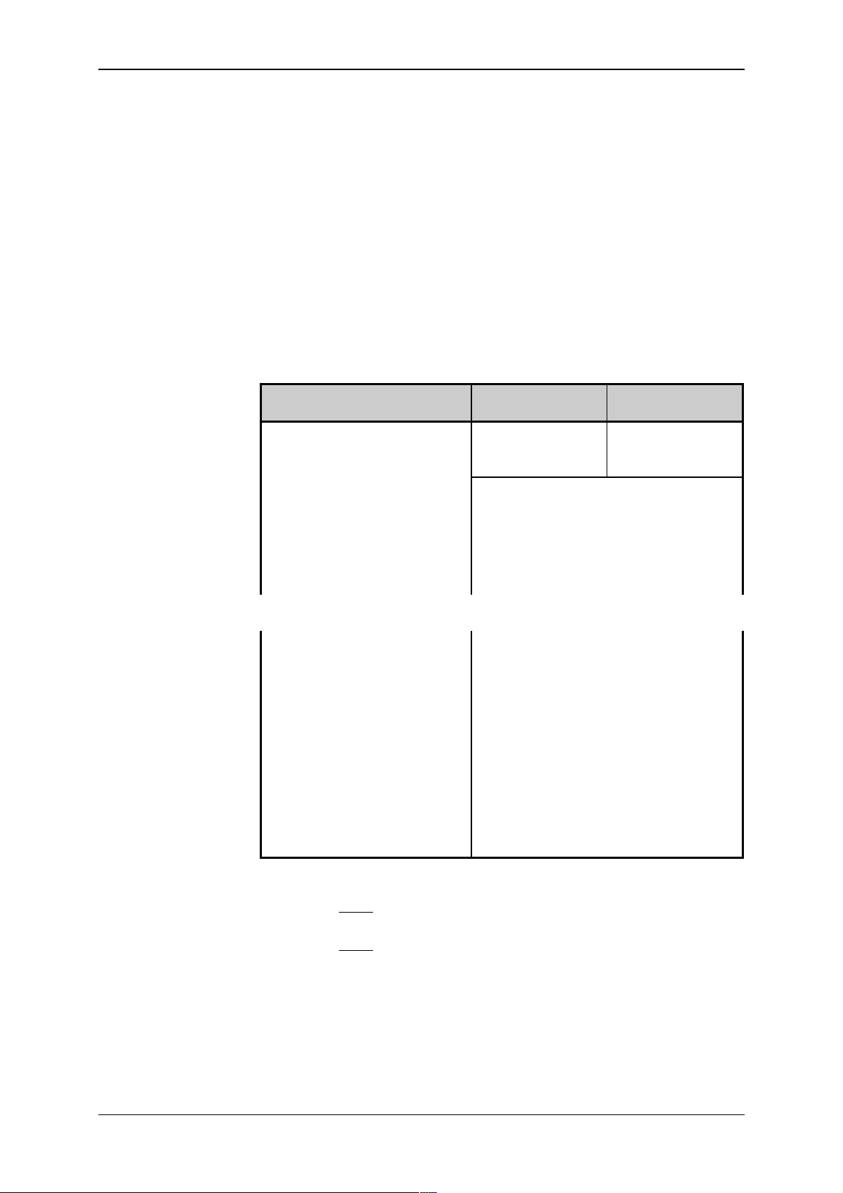
TC601 TXN 061 51 12 - 8 TC602 TXN 061 52 20 - 16 TC603 TXN 061 53._ _ 12 - 4 4
TC604 TXN 061 54._ _ 16 - - 10
TC605 TXN 061 55._ _ 12 4 - 8
TC606 TXN 061 56._ _ 16 4 4 10
TC607 TXN 061 57._ _ 20 - 20 -
1)
In types TC603 t o TC607, the after-num ber ( two digits af ter the dot)
determine the special B M function:
.00 common function of binary input s (after-number need not be given)
.01 4 interruption binar y inputs
.03 measuring by increm ental position scanner
.05 counter of type 3 (uni directi onal 16 bit counter with pre-selection)
.06 period and phase shift measurement
Optional part of al l BM t ypes are int erf ac es of t wo serial c om m unic ati ons
channels (CH1, CH2) f itted i n the standard design, addi tional data m emory
(DataBox) , and a third serial com munication c hannel (CH3) or analog outputs.
Order numbers of
optional BM
piggybacks
Type Order number Note
MR-02 5XK 068 91 Interface RS-232 without galv anic separation
from internal control ci rcui t s
MR-04 5XK 068 93 Interface RS-485 without galv anic separation
from internal control ci rcui t s
MR-09 TXK 085 03 Interface RS-485 with galv anic separation from
internal control circuits
MR-17 TXK 085 11 Interface RS-422 without galvanic separation
from internal control ci rcui t s
IM-70 TXK 080 10.00 DataB ox, additional dat a memory 128 k B
IM-70 TXK 080 10.02 DataB ox, additional dat a memory 512 k B
MR-14 TXK 085 08.02 CH3 with interfac e RS - 485 without galvanic
separation f r om inter nal control c ircuit s
MR-15 TXK 085 09.02 CH3 with RS-232 without galvanic separat ion
from internal control ci rcui t s
OT-13 TXK 082 60 4 analog outputs without galvanic separation
from internal control ci rcui t s
OT-14 TXK 082 61 8 analog outputs without galvanic separation
from internal control ci rcui t s
1)
DataBox is added in the production plant exclusively
2)
Only 1 pi ggy bac k M R- xx or 1 piggyback OT - xx may be fitted
2)
2)
2)
1)
1)
2)
Number of binary and analog inputs and binar y output s of the BM can be
extended by connecting one extension module (EM), two half extension modules (EM/2) or by combination of EM, EM/2.
TXV 138 08.02 6
Page 7

Technical equipment of TC600 PLC
Order numbers of E M
and EM/2, PLC of the
TC600 series
Type Order number Note
Binary
inputs
Analog
inputs
Transist.
outputs
Relay
outputs
TC621 TXN 061 71 12 - 8 TC622 TXN 061 72 20 - 16 TC623 TXN 061 73 12 - 4 4
TC624 TXN 061 74 16 - - 10
TC625 TXN 061 75 12 4 - 8
TC626 TXN 061 76 16 4 4 10
TC631 TXN 061 81 8 - 8 TC632 TXN 061 82 8 - - 8
TC633 TXN 061 83 16 - - TC634 TXN 061 84 - 8 - -
2.6 Design
Modules of PLC's of the TC600 series are designed as devices to be
E N 50022
(idt EN 50022:1977). Metal jacket of the modules and m echanical arrangement guarant ees hi gher r esi stanc e against interferences.
BM electroni c circ uits are real ized on t wo printed wiri ng boards; the central uni t and input and output unit.
EM's are fitted with t he input and output unit only.
7 TXV 138 08.02
Page 8
Tecomat TC600
Number of inputs and
outputs of PLC TC600
series
3. Parameters Overview
3.1 Basic Properties
TC601
TC621
Binary inputs
Total number of inputs 12 20 12 16 12 16 20
Arrangement
(no. of groups x no. o f inputs)
Binary transistor out put s
Total number of out puts 8 16 4 - - 4 20
Arrangement
(no. of groups x no. o f outputs)
Binary relay outputs
Total number of out puts - - 4 10 8 10 Arrangement
(no. of groups x no. o f outputs)
Analog inputs
Total number of inputs - - - - 4 4 Arrangement
(no. of groups x no. o f inputs)
Analog outputs
Total number of out puts
Arrangement
(no. of group x no. of outputs)
TC602
TC622
1x8,
1x4
2x8,
1x4
TC603
TC623
1x8,
1x4
TC604
TC624
TC605
TC625
2x8 1x8,
1x4
TC606
TC626
TC607
2x8 2x8,
1x8 2x8 1x4 1x4 2x8,
1x4 2x4,
2x1
2x4 2x4,
2x1
1x4 1x4
TC601 to TC606
4 or 8 - optional
1x4 or 1x8
1x4
1x4
TC631 TC632 TC633 TC634
Binary inputs
Total number of inputs 8 8 16 Arrangement
(no. of groups x no. o f inputs)
2x4 2x4 4x4
Binary transistor out put s
Total number of out puts 8 - - Arrangement
(no. of groups x no. o f outputs)
1x8
Binary relay outputs
Total number of out puts - 8 - Arrangement
(no. of groups x no. o f outputs)
2x4
Analog inputs
Total number of inputs - - - 8
TXV 138 08.02 8
Page 9

Technical equipment of TC600 PLC
3.2 Operational Conditions
Class of environment effect 33 2000-3
(mod IEC 364- 3:1993)
Range of operational temperatures
Aver age temperatur e dur ing 24
hours
Allowed transportation temperature
Relative ai r humidi ty 50 % to 95 % without condensation
Degree of pol lution
(idt EN 61131-2:1992, IEC 1131-2: 1992)
Ov er vol tage category of installation
33 0420
(eqv IEC 664:1980, IE C 664A :1981)
Immunity against disturbances
(idt EN 61131-2:1992, IEC 1131-2: 1992)
Emitted disturbance levels for gr oup 1, class A
Vibrations Fc 10 Hz to 150 Hz, 0.15 mm, 10 cycles
!
IEC 68-2-6:1995+Corr.1995)
Operating posi tion vertical
Type of oper ation permanent
0 °C to +55 °C
max. +50 °C
-25 °C to +70 ° C
(tab. 16)
(mod CISP R 11:1997)
(idt EN 60068-2- 6:1995,
3.3 Basic Parameters
BM EM EM/2
Type of appliance to be built-in
Class of el. object
(mod IEC 536- 1:1976, IEC 536-2: 1992)
Coverage IP-10B
Supply voltage
(SELV)
Power input max. 20 VA
Mass about 0.8 kg about 0.4 kg about 0.2 kg
Size (h x w x d)
1)
Power input of B M extended by one EM and one E M /2
2)
See fi gs. 9.1, 9.2, 9. 3
2)
24 V~ ±20 %,
50-60 Hz ±5 %
or 24 V- ±20 %
or 13 W
1)
141x182x69 141x157x44 141x89x44
9 TXV 138 08.02
Page 10

Tecomat TC600
4. Central Unit
4.1 Basic Parts and Parameters
Central unit ensures the majority of PLC control functions. Due to its
properties, i t i s ranked am ong T ecom at CP U D series. It contai ns especi al ly
the supply voltage converter, microcontroller, memories RAM and
EEPROM, RTC circuit , lithium battery to supply v oltage to the RAM mem ory and RTC cir cui t i n the c ase that t he PLC power supply i s t urned of f , t wo
serial communication channels and optional additional data memory and
analog output circuit s or a t hird serial c ommunication channel.
CPU Basic
parameters
Central uni t series D
Real time circ uit (RTC) fitted i n standar d desi gn
User program source m emory fitted in standard design
Memory type EEPROM (FLASH)
Memory size 32 kB
User program and data memory fitted in standard design
Memory type RAM
Memory size 32 kB
Additi onal data memory, Dat aB ox optional
Memory type RAM
Memory siz e 128 kB or 512 kB
Backup of the RAM memory and RTC min. 20 000 h
Cycle peri od per 1k of logic instruct ions 13 ms
Total number of user registers 8 192
Number of remanent r egisters optional 0 to 512
Total number of timer s and count er s 4 096
Range of timers 65 536 x 10 ms to 10 s,
possibility of cascading
Range of counter s 65 536, possibility of cascading
Instructi on set extended
Instructi on length 1 to 6 bytes
Number of serial communi c ation chan-
nels
Transmission speed of CH1, CH2, CH3 0.3 t o 230.4 kBd
Number of analog outputs optionally 0, 4 or 8
2 + 1, optional
1)
1)
Maxim um tr ansmission speed is lim ited by the max im um al lowed transmission speed of the set communication channel m ode.
4.2 User Accessible Memories
User program
memory
User program source
memory
TXV 138 08.02 10
Memory of the user program is f orm ed by a part of the RAM m em ory of
CPU assigned for the user progr am, data and tabl es. When PLC is turned
off, the m emory is supplied by the built-in lithi um battery .
Source memory of the user program is formed by a part of the EEPROM
memory of CPU assigned for saving of a copy of the user program. The
memory power-independent, that is, contents of the memory remain retained even after the power supply of the PLC is turned off or when the
battery i s di scharged. Use of the source memory is contr olled by the user by
setting a parameter in t he P LC S E T mode (see Article 4.5) .
When the source mem or y is allowed, after exiting the SET mode, turning
on of the PLC power supply or restart, c ontents of the user program source
memor y is mov ed to the user program mem ory with which CP U works. The
functi on is used especially for backup of the user program. The m emory is
programmed from within t he devel opment environment direc tly in the PLC.
Page 11

Technical equipment of TC600 PLC
Memory of CPU
parameters
Scratchpad memory
The DataBox
Support of w or k ing
with the Dat aB ox
Backup of the RAM
memory and RTC
circuit power s upply
Detection of state of
the backup batter y
Memory of CPU param eters is power-independent m emor y designed for
storage of param eters that can be set in the PLC SE T mode. Contents of
the mem ory rem ain ret ained ev en when the PLC power supply i s turned off
or if the battery is discharged.
The scratchpad m emory is a part of the CPU RAM memory accessible to
the user in the f orm of i nput i mages (regi sters X), outputs i mages ( registers
Y), system (S) and user registers (R). Preserving of the scratchpad cont ents
after t urni ng of f of the PLC power supply and restart s i s program - contr oll ed.
The behav iour is described in detail in Chapter 10.
The DataBox is an optional compl ement of the CPU, fi tted by the producer on the basis of an or der. I t ex t ends t he user accessibl e RAM m em ory
by 128kB or the data memory by 512kB. When the P LC is turned off, the
memor y is supplied fr om a bui lt-i n li thium batt ery. It is designed f or working
with greater amounts of data, f or exampl e for arc hiv ing of dat a on the controll ed process for a longer t ime period et c. The data can be writt en to the
memory or read, respectively, either by using the PLC user program or
through the serial line.
For support of the DataBox program attendance, there are thr ee user instructions available. The READDBX instruction is intended for reading of
data from DataBox into R regi sters, the WRI TEDBX instructi on is intended
for writing of data from R registers to the DataBox, and the SIZEDBX instruction serv es for identi fication of the DataBox size. Detailed descripti on
of function of instructions, their definitions, structures of the parameters
zone for i nstructions READDBX and WRI TEDBX and way of c alling of instructions in the user program are given on t he distribution disket te xPRO
which forms a part of the PLC delivery.
For serial communication with the DataBox, either CH1 can be used
which always operates in the PC m ode or c hannels CH2, CH3 set i n the PC
mode. To support serial communication with the DataBox, the
COMPLC.EXE program is av ai labl e which all ows for reading data f rom DataBox i nto a fi le or write dat a from a fil e to DataBox , respectiv ely, and test
size of memory accessible in the form of the DataBox. W orking with the
DataBox i s possible starti ng from the CO MPLC.EXE program version 1. 6.
The program, which is found on the x PRO distr ibuti on diskett e, must be r un
under the MS DOS oper ating system.
When the PLC power is turned of f, the RA M memory and RTC circuit are
supplied from a bui l t-i n l i thi um batt ery. Param et ers of the used batt ery al l ow
for backup wit h the power supply turned of f f or the m ini mum t im e of 20000
hours. In common operating conditions (operating temperature of 20 °C,
unidirectional operation at least) and typical power take-off of the backing
circui ts, the backup time is l imi ted by battery life (5 years at the minimum).
Voltage of the backup battery i s evaluated by the diagnostic system. In
the case the vol tage drops under 2.5 V, bit .0 of the S35 system regi ster is
set to the state log. 1. PLC cont inues with it s activ i ty unti l t he v oltage drops
under the minimum supply voltage of the RTC circuit. Evaluation of the
RTC circuit failure leads to bringing the PLC in the HALT mode and announcing the error message 80 0C 00 00.
11 TXV 138 08.02
Page 12

Tecomat TC600
4.3 Analog Outputs
Analog outputs are used for control of v olt age-control acti on elem ents of
the control led obj ect . T hey are ar ranged i n a group wit h a com m on ter m inal
of the analog ground. Analog outputs are galvanically connected with the
CPU control circuits. Physically, the analog outputs are realised on small
plug-in units, the so called piggybacks, fitted on the CPU if ordered. Number
of output s depends on the ty pe of the chosen piggy bac k ( see Article 2.5).
Parameters of analog
outputs
OT-13 OT-14
Number of output channel s 4 8
Arrangement of outputs 1x4 1x8
Common gr oup c onduc tor minus
Galvanic separation from inter nal
control circuits
Type of output voltage
Voltage range/ r esol ution (1 LSB 1))
Error of output voltage
Binary output representation 8 bits
Output curr ent max. 10 mA
Setting time of the output
Output l oad r esi stanc e
Resistance against short-circuit min. 5 s
1)
LSB (Least Signifi c ant Bit) - lowest bit of the binar y val ue
1 LSB =
0 to 9.96 V/ 39 mV
no
typ.
1 LSB
max.
4 LSB
max. 30 s
>1 k
TXV 138 08.02 12
Page 13

To program the PLC,
communication
channel CH1 is used
Interface RS-232 of
CH1 is activated af ter
connection of the
interconnecting cable
TXK 646 51.06
Technical equipment of TC600 PLC
4.4 Serial Communication Channels
Standard design of all PLC's of the TC600 series is equipped with two
comm unication channels. Thi rd communi cation channel is added per order
(see Article 2.5).
4.4.1 Serial Communication Channel 1 (CH1)
CH1 is designed for c onnecti on of t he PLC t o a superior system . The superior system most of ten repr esents a computer of the P C class perfor mi ng
the funct i on of a program m i ng devic e, visual isati on stat ion or contr ol devi ce
of the PLC network. It contains a complete set of the EPSNET network
servi c es. Detailed description of the services is given in the handbook
Communication of T ec om at P r ogr am m able Logic Controllers,
TXV 001 06.02.
CH1 is equipped with fix ed fit ted interface RS-232 without galvanic separation f rom internal circuits. Besides this, in all types of BM, CH1 can be
complem ented with a piggyback with int erface RS- 485 or RS-422. Opt ional
interf ace is impl ici tl y assigned to CH1. Interface RS -232 is assigned to CH1
automati cally by connecting the cable TXK 646 51.06. Together with connecting interface RS-232, the optional interface (if fitted) is disconnected
from CH1. For selection of the inter face ty pe, especiall y functi on of the superior dev ice is decisiv e, type of int erfac e of i ts serial comm unicat ion channel, connect ion distance, transmission speed and level of disturbanc es.
Serial
Interface RS-232 is
used for tw o- point
connection
Parameters of the
RS-232 interface
4.4.1.1 Interface RS-232
Interface RS-232 ensures conversion of output signals of TTL level to
level defined by the specification V.28 (EIA RS-232), and of input signals
according to V .28 to the TTL l evel. I t allows for connec tion of two end devi ces in the duplex mode. I t is suitabl e for c onnection r ealised i n short di stance in an environment with low level of electrom agnetic distur banc es.
For the com municat ion, PLC's of the TC600 series use only bi nding ci rcuits of signal s TxD (Transmit Data), RxD (Receiv e Data), CTS (Cl ear To
Send), and RTS (Request To Send) of the standard RS-232 int er face.
Transmission speed max. 230.4 kBd
Cable length m ax. 15 m
Voltage of outputs TxD, RTS for level 1
Voltage of outputs TxD, RTS for level 0
typ. -8 V against GND (R
typ. +8 V against GND (R
2)
1)
=5 k
l
=5 k
l
Voltage of inputs Rx D, CTS f or lev el 1 min. -3 V against GND
max. -25 V against GND
Voltage of inputs Rx D, CTS f or lev el 0 min. +3 V against GND
max. +25 V against GND
Impedance of inputs RxD, CTS
1)
The maximum transmission speed is limited by the maximum allowed
transmission speed of the set mode of the communic ation channel.
2)
The maximum cable length may only be used provi ded that the maxi-
5 k
mum transmission speed is reduced.
13 TXV 138 08.02
Page 14

Tecomat TC600
Interface RS-485 is
used for multi-point
connection
4.4.1.2 Interface RS-485
Interf ace RS-485 ensures conversion of output signal s of t he TTL l evel
to lev el def i ned by t he specificat i on V.11 (X.27, EIA RS -485), and i nput signals according t o V.11 to the TTL lev el. Param eters of sym metric bi nding
circui ts of the RS-485 int erface all ow for mul ti-point connection of end devi ces in the half -duplex mode. It is suitable f or connection reali sed in medium di stance i n an environm ent with hi gher l evel of elect rom agnet ic distur bances.
For the communic ation, PLC's of the TC600 series use binding circuit s of
signals TxD (Transmi t Data), RxD (Recei v e Data). Signal RTS (Request To
Send) is used internally for control of the tr ansmitter ac tivation.
Parameters of the
RS-485 interface
Transmission speed max. 230.4 kBd
Cable length max. 1200 m
Sensitivity of differential inputs
±200 mV
1)
2)
RxD+, RxDInput resistance of differential inputs
min. 12 k
RxD+, RxDVoltage of different ial inputs
RxD+, RxD- f or lev el 1
Voltage of different ial inputs
RxD+, RxD- f or lev el 0
Voltage of different ial output s
TxD+, TxD- for level 1
Voltage of different ial output s
TxD+, TxD- for level 0
Difference of the output vol tage
min. 0.2 V
max. 12 V
min. -0.2 V
max. -7 V
min. 1.5 V (R
max. 5 V Io=0)
min. -1.5 V (R
max. -5 V Io=0)
max. ±0.2 V
=75
l
=75
l
value for levels 0 and 1
Output curr ent max. ±250 mA
1)
The maximum transmission speed is limited by the maximum allowed
transmission speed of the set mode of the communic ation channel.
2)
The maximum cable length may only be used provi ded that the maxi-
mum transmission speed is reduced.
TXV 138 08.02 14
Page 15

Interface RS-422 is
used for tw o- point
connection
Technical equipment of TC600 PLC
4.4.1.3 Interface RS-422
Interface RS-422 of PLC's of the TC600 series ensures conv ersion of
output signals of the TTL level to lev el defined by the specification V.11
(X.27, EIA RS-422), and input signals according to V.11 to the TTL lev el.
Parameter s of symmetr ic binding ci rcuits of t he RS-422 int erface al low for
two-point connection of end dev ices in the duplex mode. It is suitable f or
connection reali sed in m edium distance i n an env ironm ent with hi gher lev el
of elec tromagnetic disturbances.
For the com municat ion, PLC's of the TC600 series use only bi nding ci rcuits of signals TxD ( Transm i t Dat a) and Rx D (Recei ve Data) of the RS-422
interf ace.
Parameters of the
RS-422 interface
Transmission speed max. 230.4 kBd
Cable length max. 1200 m
Sensitivity of t he differenti al input
±200 mV
1)
2)
RxD+, RxDInput resistance of the diff er ential
min. 12 k
input Rx D+, RxDVoltage of the differ ential input
RxD+, RxD- f or lev el 1
Voltage of the differ ential input
RxD+, RxD- f or lev el 0
Voltage of the differ ential out put
TxD+, TxD- for level 1
Voltage of the differ ential out put
TxD+, TxD- for level 0
Difference of the output vol tage
min. 0.2 V
max. 12 V
min. -0.2 V
max. -7 V
max. 5 V Io=0)
2.3 V (R
=100
l
max. -5 V Io=0)
-2.3 V (R
=100
l
max. ±0.2 V
value for levels 0 and 1
Output curr ent max. ±60 mA
1)
The maximum transmission speed is limited by the maximum allowed
transmission speed of the set mode of the communic ation channel.
2)
The maximum cable length may only be used provi ded that the maxi-
mum transmission speed is reduced.
15 TXV 138 08.02
Page 16

Tecomat TC600
CH2 is designed for
general use
CH3 is designed for
general use
4.4.2 Serial Communication Channel 2 (CH2)
CH2 serves especial ly f or connect ion of int elli gent peri pheries with a serial input or output of data to the PLC, and for mutual interconnection of
PLC's. It can operate in sev er al modes:
Mode PC - c onnec tion of a superior system, usually a PC
Mode PLC - interconnection of PLC's or regulators for mutual tr ansfer of
data
Mode MAS - data collection from subordinate PLC's or regulators in the
EPSNET network
Mode uni - general user channel for universal use
Setting of the required mode is giv en in Arti cle 4.5, detai led descripti on
of the m odes is given in the handbook
Serial Communication of Tecomat
Programmable Logic Contr oller s , TXV 001 06.02.
CH2 interf ace is optional (see Article 2.5). Parameters of the interf ace
are given under item 4.4.1.
4.4.3 Serial Communication Channel 3 (CH3)
CH3 is an optional par t of the P LC. It can be complem ented only in types
without analog out puts. It serv es especially f or c onnection of i ntelli gent peripheries with a serial input or output of data or connecti on of an external
control board, mutual interconnect ion of P LC's or connection of a PLC to a
superior system. It can operate in several modes:
Mode PC - c onnec tion of a superior system, usually a PC
Mode PLC - interconnection of PLC's or regulators for mutual data
transfer
Mode MAS - data collection from subordinate PLC's or regulators in the
EPSNET network
Mode uni - general user channel for universal use
Setting of the required mode is giv en in Arti cle 4.5, detai led descripti on
of the m odes is given in the handbook
Serial Communication of Tecomat
Programmable Logic Contr oller s TXV 001 06.02.
CH3 interfac e is dependent on the type of the c omm unicat ion piggy back
(see Article 2.5). Interface par ameters are given under item 4. 4.1.
TXV 138 08.02 16
Page 17
Mode SET
Displaying of
parameters
Entrance in the SE T
mode
Termination of the
SET mode
Adjustable
parameters
Technical equipment of TC600 PLC
4.5 Setting of CPU Parameters
CPU parameters are set in the setting mode (mode SET). To set and
display paramet ers, the PLC front boar d is equipped with buttons SET and
MODE and a one-plac e seven-segment LE D display.
In the SET mode, all data are displayed in the rotational way, that is,
number 123 is displayed in such a way that digits 1, 2, 3 are l ighted gradually on the display, then there is a delay, and the whole sequence is repeated. Ev ery character i s displayed for about 0. 5 s and is separated f rom
the foll owing charac ter by a delay which ensures recognit i on of two ident i cal
characters display ed one aft er another (f or ex ampl e, di splaying of the num ber 111).
Switching t o the SET mode can be perf ormed by pressing butt ons SET
and MODE sim ultaneously whil e the PLC power supply is on. Buttons S ET
and MODE are held pr essed unti l the triple dash appears on the display. In
general it holds that by t he SET butt on we change setting of the param eter,
and by the MODE but ton we mov e t hrough i ndiv i dual paramet ers. Pressing
of the but ton is indic ated by lighting of the decim al point on t he display.
The SET mode m ay be term inated any ti me by sim ultaneously pr essing
the buttons SET and MODE. W e again hold the buttons SET and MODE
pressed until the t r iple dash appears on the display. Stat e of param et ers is
saved upon term ination of the mode in the power-independent m emory of
parameters, and the PLC switches to the HA LT m ode or som e of err or m essages may possibly be signalled.
Tab. 4.1 Adjustable CPU parameters
(ordered fr om the left to the right and in the rows)
Setting of t he s er ial
channel mode
Object to
Adjustable parameters
be set
channel CH1 - address speed delay of re-
ply
CTS detec-
tion
off - - - -
channels
CH2 and CH3
Program source
mode PC
reg. PLC
1)
reg. uni
mode
MAS
address speed delay of re-
ply
address speed - -
- speed transport
delay
-- - -
off
CTS detec-
tion
CTS detec-
tion
2)
memory
on
1)
Only BM's fitted with the communication piggyback contain channel
CH3.
2)
CTS detection in the MAS mode cannot be set for CH3.
4.5.1 Setting of Parameters of Serial Communication Channels CH1,
CH2, CH3
Channel CH1 has fixed-set mode PC which c annot be changed. In this
channel, the par ameter serial channel mode is not set.
In setting the parameter serial channel mode for c hannels CH2, CH3, a
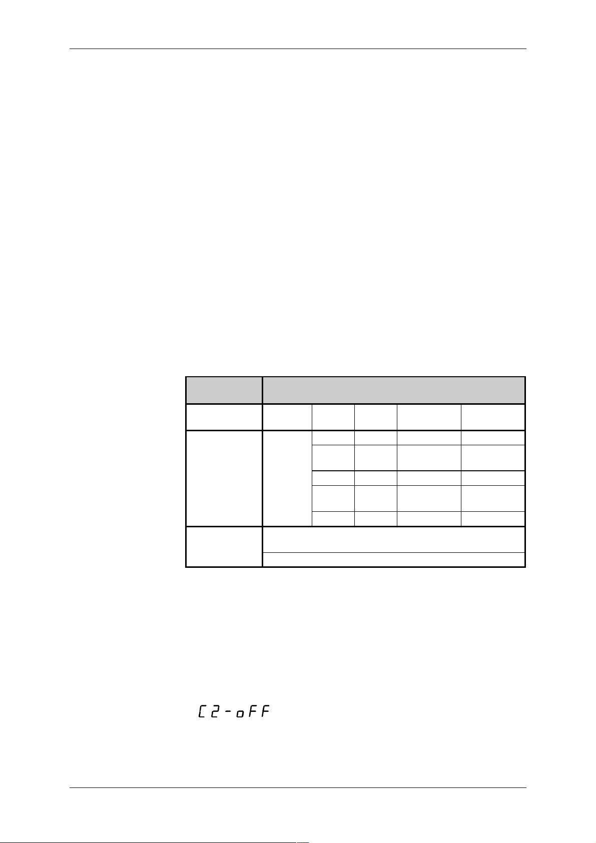
message of the foll owing type is shown on the display
with the f ollowing m eaning:
C - setting of t he serial channel mode
2 - number of t he c hannel being set
off- the mode being set
Serial c hannels may operate in the f ollowing m odes:
17 TXV 138 08.02
Page 18
Tecomat TC600
off - channel is of f (no other c hannel paramet er is set)
PC - connection of a superior system (a PC or an active operation
board)
PLC - interconnect ion wit h other PLC's or regul ators i n t he EPSNET m ul-
tim aster network with fast dat a exchange
MAS - data collection from subordinate PLC's or regulators in the
EPSNET network
uni - general user channel for univ er sal use
By the SET but ton we move t hrough indiv idual modes. B y pressing the
MODE button we save the set mode and move to setting of another parameter
Setting of t he s er ial
channel address
Setting of t he s er ial
channel communication speed
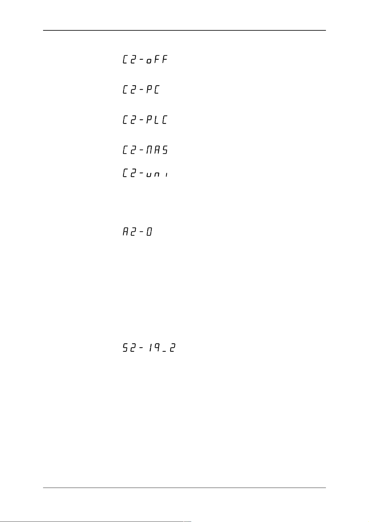
When sett ing the param eter serial ch annel add ress, a message of the
following type is shown on the display
with the f ollowing m eaning:
A - setting of t he serial channel addr ess
2 - number of t he c hannel being set
0 - the set addr ess
Address may take a value from 0 to 99. By shortly pressing the SET
button, we increase i ts val ue by 1, by pressing and holdi ng the SET button
(for about 1s) we incr ease i ts val ue by 10. By pressing the MODE button, we
save the set value and move to setting of another parameter.
Address is set only f or modes PC and PLC. In the uni mode, setting of
the address is a part of the init ialisation table in the user program.
When setting the parameter serial channel communication speed, a
message of the foll owing type is shown on the display
with the f ollowing m eaning:
S - setting of the serial channel c ommunication speed
2 - number of the channel being set
19_2 - set speed in kb/s (the underscore is a substitute for the decimal
point)
The speed may take v alues defined in adv ance according to t able 4.2.
Speed not av ailabl e in the giv en m ode of the gi ven channel, i s not of fered
when browsing by the SET button. By pressing the MO DE button, we save
the set v alue and move to setting of anot her par ameter.
The speed is set only f or modes PC, PLC and MAS. In the uni m ode,
speed setting is a part of the initialisation t able in the user program.
TXV 138 08.02 18
Page 19
Technical equipment of TC600 PLC
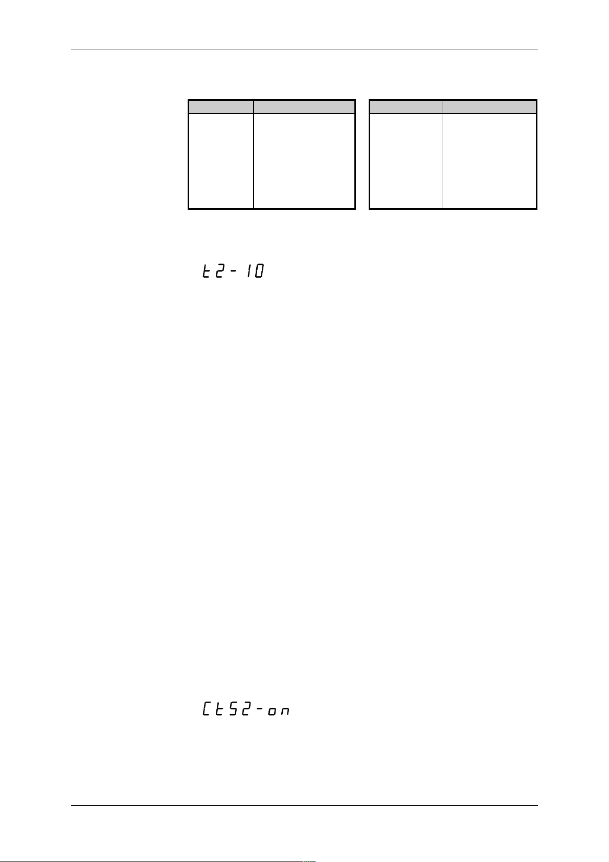
Tab. 4.2 List of available transmission speeds of CH1, CH2 and CH3 in
various modes
Speed Channel mode Speed Channel mode
0.3 kb/s PC,MAS 28.8 kb/s PC,PLC,MAS
0.6 kb/s PC,MAS 38.4 kb/s PC,PLC,MAS
1.2 kb/s PC,MAS 57.6 kb/s PC,PLC,MAS
2.4 kb/s PC,MAS 76.8 kb/s PLC
4.8 kb/s PC,MAS 115. 2 k b/s PLC
9.6 kb/s PC,PLC,MAS 172.8 kb/s PLC
14.4 kb/s PC,PLC, M A S 230.4 kb/s PLC
19.2 kb/s PC,PLC, M A S
Setting of t he r eply
delay and transport
delay
Reply delay
Transport delay
When sett ing the param eter reply delay (in the PC m ode) or transport
delay (in the MAS mode), a message of the f ollowing type i s shown on the
display
with the f ollowing m eaning:
t - setti ng of the reply delay
2 - number of t he c hannel being set
10 - set delay/transport delay in ms
By shortly pressing the SET button, we increase the value of the delay/tr ansport delay by 1, by pr essing and holding the SET button (f or about
1s) we increase its v alue by 10. B y pressing the M ODE button we save the
set value and move to setting of another par ameter.
Optional reply delay serv es for solut ion of si tuations when the superior
system sending the message, cannot switch in time from transmission mode
to receiv ing m ode, and thus it cannot receiv e t he PLC's reply. By ex tending
the reply delay t he superior system gai ns time f or preparati on necessary to
start receivi ng of a reply .
The delay ti m e i s set in m s and m ay take values f rom 0 to 99 m s. Val ue
0 means that the mini mum reply delay shall correspond with the time necessary to transmit 1 byte, thus it depends on the set speed. Val ues 1 to 99
give the delay in milliseconds and are not dependent on the comm unicati on
speed.
The reply delay is set only for mode PC.
Optional transport delay serv es for soluti on of si tuat ions when the PLC i n
the role of the superior system is waiting for reply from a subordinate PLC
for l onger than 0.5 s for t he r eason of delay on the t r ansmission l ine, caused
by modem s etc .
Transport delay is set in multipl es of 100 m s and may take values from 0
to 6 s. Value 0 means that the superior PLC waits for the reply for the
maxi mum of 0.5 s (ti me of cycle of the subordinate PLC may not exceed
this value). Values 1 to 60 give the transport delay of 0.1 to 6 s which is
added to the v alue 0. 5 s. Values 61 to 99 set the m ax im um transport delay
of 6 s.
The transport del ay is set only f or mode MAS.
Setting of t he CTS
signal detection
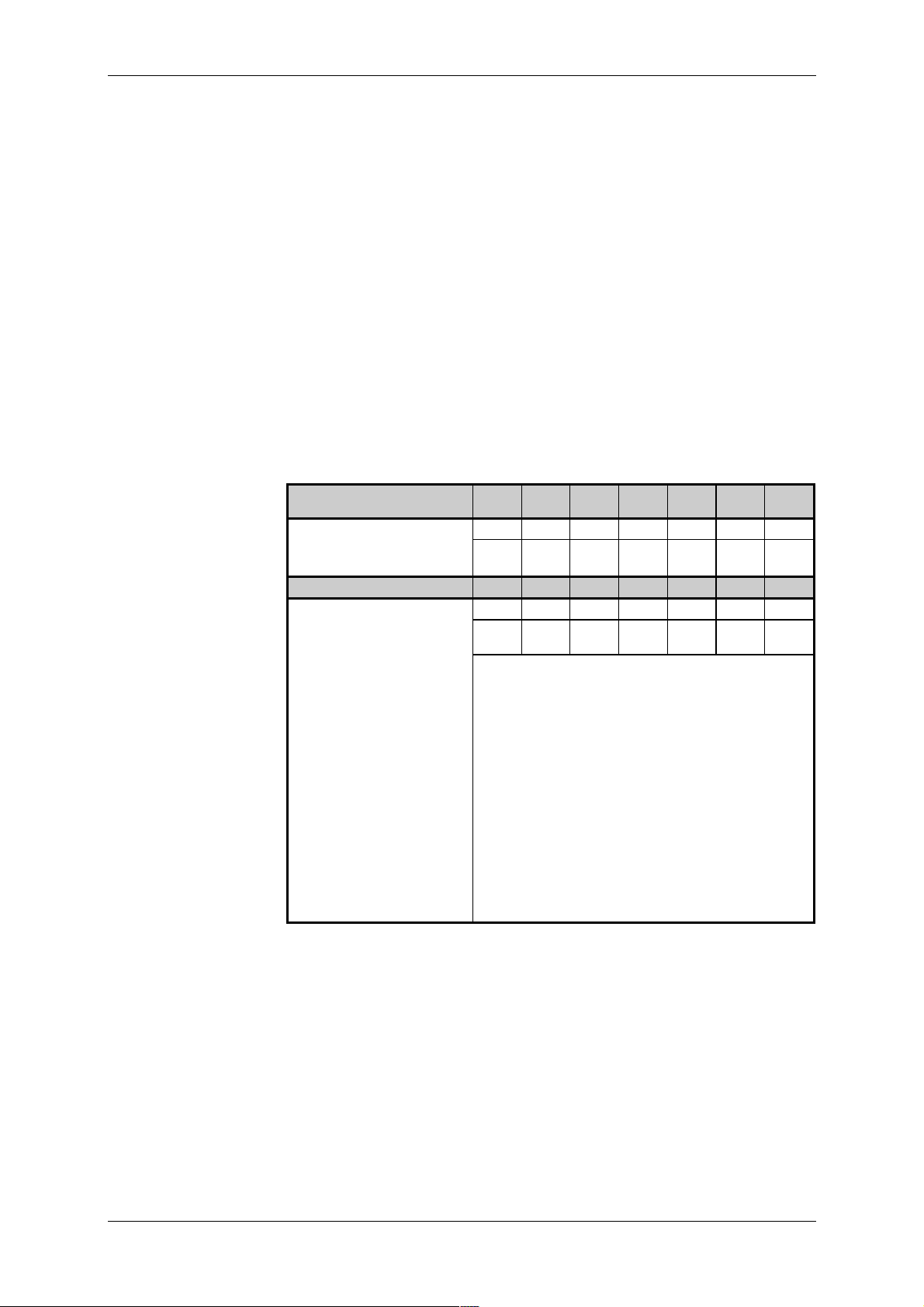
When setting the param eter CTS signal detection, a message of the
following type is shown on the display
with the f ollowing m eaning:
CTS - setting of the CTS signal detection
2 - num ber of the channel being set
on - det ec tion on
19 TXV 138 08.02
Page 20

Tecomat TC600
Detection of the CTS si gnal may be either of f or on. By pressing the SET
button we change the setting, by pressing the MODE butt on we save t he set
value and move to setting of another par ameter.
When detect ion of the CTS signal is on, bef ore t ransmission of the repl y
the PLC tests state of the CTS signal af ter setti ng the RT S signal . The repl y
is transmitt ed only if the CT S signal has the sam e v alue as the RTS signal.
This mode i s suitable for com municat ion vi a modems. The set reply delay
holds in this mode too, it is thus ensured that PLC shall not reply before t he
delay elapses even if the CTS signal is already set.
When CT S signal det ecti on is of f, PLC control s the RTS signal but does
not take into considerati on state of the CTS signal.
Detection of the CTS si gnal can be set for the PC mode of all channel s
and for the MAS mode f or channel CH2. For channels CH2 and CH3 in the
uni mode, detec tion of the CTS signal c an be set using the ini tiali sation table in the user progr am.
Default sett ing of
parameters
Parameter s of CH1 are implicitly set by the producer to the following
values: mode - PC, addr ess - 0, speed - 19.2 k b/s, delay - 0, CTS detection
- off
CH2 and CH3 are implici tly off.
4.5.2 Management of the user p rogram source memo ry
When setti ng parameters of the source memory, a message of the fol lowing type i s shown on the display
with the f ollowing m eaning:
EP - setting of the user program source memory
off- m emory off (default val ue)
The source mem ory m ay be eit her of f or on. By pr essing t he S ET but ton
we change the setting, by pressing the MODE but ton we save t he set v alue
and move to setti ng of another parameter.
When t he param et er i s set to the of f v al ue, after t he PLC switches to t he
RUN mode, program stored in the user program memory i s run. When t he
parameter is set to the on value, after the setting mode is ended and in
every subsequent turning on of the PLC power supply, program from the
source memory is first moved to the user program m emory, and this program is then run in the RUN mode. The function serves especially for
backing of power-dependant memory of the user program.
TXV 138 08.02 20
Page 21
Technical equipment of TC600 PLC
5. Input and Output Unit
5.1 Basic Functions
The majori ty of input and output circui ts of the PLC is real ized on t he input and output unit. Indiv idual types of the series diff er in the type of the
used input and output unit or i n m odificat i on of the uni t f i tt ing wit h ci rcui t s of
binary and analog inputs and binary t r ansi stor and r elay outputs.
5.1.1 Binary Inputs
Binary i nputs serve for c onnection of t wo-state signals of the contr olled
object to t he PLC. To increase f unctional rel iability, every input is galv anically separated by an optical el ement f rom i nternal ci rcuits and is equi pped
with a fi l ter. If the i nput i s exc it ed (cl osed), t hi s is signall ed by l i ghti ng of t he
LED diode. Input s are organized in groups with one c ommon connec tor. A
group of signals may be connected in one or the other polarity .
Inputs DI1 to DI3 of modules TC603 to TC607 can be used for basic
functi on i denti cal wit h other i nput s or f or real i zati on of t he PLC speci al functions.
Parameters of binar y
inputs
TC601
TC621
Total number of inputs 12 20 12 16 12 16 20
Arrangement
(no. of groups x no. o f inputs)
TC631 TC632 TC633 TC634
Total number of inputs 8 8 16 Arrangement
(no. of groups x no. o f inputs)
Group common conductor plus or mi nus
Galvanic separation f r om
other electric circuits
Nominal vol tage 24 V-, 24 V~
Voltage for log. 0 max. 12 V-, 11 V~
Voltage for log. 1 min. 16 V- , 15 V~
Current for log. 1 typ. 10 mA
Delay from log. 0 t o log.1 typ. 4 ms
Delay from log. 1 t o log.0 typ. 4 ms
Pulse overload capacity of
the input
TC602
TC622
1x8,
1x4
2x4 2x4 4x4
TC603
TC623
2x8,
1x4
1x8,
1x4
(max. 14 V-, 13. 5 V~)
(min. 18.5 V-, 17.5 V~)
max. 30 V-, 30 V~
(pulse width 100 s, period 1 s)
TC604
TC624
2x8 1x8,
yes
max. 250 V
TC605
TC625
1x4
TC606
TC626
2x8 2x8
1)
1)
TC607
1x4
1)
Value val i d for inputs DI0 to DI3 of m odul es TC603 to T C607 and TC623
to TC626
21 TXV 138 08.02
Page 22
Tecomat TC600
5.1.2 Binary Transistor Output s
Binary tr ansistor outputs serv e f or contr ol of two-state act ion and signal ling el ements, which require hi gh count and el. cl osing speed. To i ncrease
functional rel iability, every output is galvanically separated by an opti c al element fr om internal cir cui ts and is protect ed against short ci rcui t, overv ol t age
and rever si ng of polarity.
When connecting an external power supply of outputs, closing of individual outputs i s signalled by lighting of the LED di ode. By lighting, the common LED diode marked as BLK, signals blocking of outputs in the still
(open) state.
Outputs are organi z ed in groups with one common connector.
Parameters of
transistor outputs
TC601
TC621
TC602
TC622
TC603
TC623
TC604
TC624
TC605
TC625
TC606
TC626
TC607
Total number of out puts 8 16 4 - - 4 20
Arrangement
(no. of groups x no. o f outputs)
1x8 2x8 1x4 1x4 2x8
1x4
TC631 TC632 TC633 TC634
Total number of out puts 8 - - Arrangement
(no. of groups x no. o f outputs)
1x8
Group common conductor plus
Galvanic separation f r om
yes
other electric circuits
Operational volt age of out-
9.6 V- to 28.8 V-
puts
Current of outputs max. 1 A
Current of the comm on
conductor
Residual current in el.
max. 6 A max. 4 A 6 A
4 A
max. 300 A
opening
El. closing time
El. opening time
Protection against short
max. 400 s
max. 400 s
yes
circuit
Limi t at ion of the initi al peak
typ. 7.5 A
current
Disconnecting tim e of the
typ. 4 ms
initial peak current
Limitation of short circuit
typ. 4 A
current
Protection against overload yes
Current limitation typ. 4 A
Protection against revers-
yes
1)
ing of polari t y
Servicing of inducti ve load external
1)
The circuit is brought in non-activ e state, loads are closed, current will
flow through the circuit protect iv e diode.
TXV 138 08.02 22
Page 23
Technical equipment of TC600 PLC
5.1.3 Binary Relay O utputs
Binary rel ay outputs serve for control of two-state action and signalling
element s of the cont roll ed object , suppli ed by alter nating v ol tage or v oltage
higher than the allowed range of closed volt age of transistor outputs. O utputs are realized by the closi ng v oltage-f ree cont act rel ay led out independently or in a group with one com mon connector.
Closing of every output is signalled by lighting of the LED diode. The
comm on LED diode mark ed as BLK, signals by li ghting bl ocking of outputs
in the still (open) state.
Parameters of r elay
outputs
TC601
TC621
TC602
TC622
TC603
TC623
TC604
TC624
TC605
TC625
TC606
TC626
Total number of outputs - - 4 10 8 10
Arrangement
(no. of groups x no. of outputs)
TC631 TC632 TC633 TC634
1x4 2x4,
2x1
2x4 2x4,
2x1
-8-2x4
Galvanic separation from
yes
other elect r ic circ uits
Contact parameters
Closed voltage
max. 250 V
Closed current max. 1 A
Closed alternat ing output m ax. 250 VA
Closed direct- c ur r ent output m ax. 24 W f or vol tage 24 V
max. 43 W for voltage 48 V
max. 57 W for voltage 250 V
Current through t he gr oup
max. 4 A
comm on c onduc tor
Closing and opening t ime typ. 5 ms
Oscillation time typ. 1 ms
6
Mechanical life min. 20 x 10
closings
Serv icing of inductiv e load external
Protection of the c ontact
external
against overload
Dielect r ic resistance of the
1 kV~
open contact
Dielect r ic resistance between
2.2 kV~
relay contac ts and non-live
PLC parts
Dielect r ic resistance between
3.75 kV~
relay contac ts and SELV circuits
Dielect r ic resistance between
contact groups
1)
3.75 kV~
1)
Includi ng c ontacts led out independently
23 TXV 138 08.02
Page 24
Tecomat TC600
Format of input data
5.1.4 Analog Inputs of TC605, TC606, TC625, TC626 Modules
Analog inputs serve for connection of up to four analog signals of the
controll ed object to the PLC. They are i ntended especial ly f or processing of
analog signals with normalized current or v oltage level. Input circuits are
galvanically connected wit h internal P LC c ontrol ci r c uits.
Inputs are arranged in a gr oup with one common connector of t he analog
ground. Ev ery input can be set indi viduall y by a jumper f or the voltage or
current signal source. T he m easurement range i s set by a pr ogram . T ype of
input and the measurement range c an be selected for every i nput independently of other inputs.
Value of the i nput v ar iabl e i s passed in the FS form at (F ul l S cal e). V alue
0 of the input data corresponds with the lower limit of the measurement
range, the maxi mum v alue of t he input data 4095 cor responds with the upper limi t of the measurem ent range. E x ceedi ng of the c onv er ter r ange is not
signalled. Conversion to technical units is performed on the user program
level. The FS format provides the highest possible resolution.
Parameters of analog
inputs
TC605, TC606,
TC625, TC626
TC601 to TC604
TC621 to TC624
TC605, TC606
TC625, TC626
Number of input channels - 4
Arrangement
1x4
(no. of gr oups x no. of inputs)
Group common conductor minus
Galvanic separation from inter -
no
nal elect r ic circ uits
Input binary r epr esentation 12 bits unsigned
Conversi on time of 4 channels 4 ms
Input type cur r ent or v oltage
Voltage inputs
Measurement range/ r esol ution
(1 LSB)
Input resistance
Recomm ended internal r esi s-
0 V to +10 V/
0 V to +2 V/ 0.49 mV
>10 M
<10 k
2.44 mV
tance of the signal source
Current inputs
Measurement range/ r esol ution
0 mA to +20 mA/
4.9 A
(1 LSB)
Input resistance
100
Input current max. 50 mA
Input voltage max. 5 V
1)
2)
LSB (Least Signifi c ant Bit) - lowest bit of t he binary value
1)
1 LSB =
2)
1 LSB =
TXV 138 08.02 24
Page 25

Switching of the
current source allows
for connection of two
detector st r ings with
impedance up to 8 k
Technical equipment of TC600 PLC
5.1.5 Analog Inputs of the TC634 Module
Analog input s serve f or connection of up t o eight analog signals of the
controll ed obj ect t o the P LC. T hey are i ntended especial l y f or m easurem ent
of temperatures using passive resistance temperature scanners, and for
processing of analog signal s with normali zed current or v ol tage lev el. Input
circui ts are galvanically connected wit h the PLC internal control c ircuit s.
Inputs are fi xed-confi gured as differenti al ones. Ev ery input can be set
individually using a jumper for direct-current voltage or current signal
source. Measurement r ange and form at of the input variabl e val ue ar e set in
a program. Input type, m easurement range and f ormat of t he v alue of input
data can be selected for every input independently of other inputs.
To supply power to passiv e resistance detector s, an internal power supply prov iding speci fic current 1 mA is av ailable, which is switched in m easurements automatically to one of the two output c lips.
The modul e ensures fil tering off of the disturbance com ponent of input
signals, protect ion of input circ uits, conv er sion of t he analog v ol tage or cur-
rent input level to the binary value, and conv ersion of the value into the
chosen form at.
Parameters of analog
inputs of TC634
Number of input channels 8
Arrangement of input s 8 differential
Method of A /D conv er si on si gma-delt a modulation
Input f iltration digital filter 50 Hz
Calibrat ion automatic at the PLC initialization
and at ev er y c hange of the measure-
ment range
Conversi on time of one channel 60 ms
Reconfiguration time of one channel
Total measurement t ime
Input response time
2)
3)
1)
180 ms
variable according to configuration
60 ms
Binary representation of the input 16 bi ts
Galvanic separation from inter nal
no
electric circuits
Galvanic separation from non-live
yes
PLC parts
Input type
(can be selected by a jumper)
voltage - passive resistance scanners of
1)
Reconfiguration time of one channel is time necessary to change and
current
voltage
temperature
calibrate the measurement range and conversion of one channel. It is
applied at transferring among diff er ent input ty pes.
2)
Total m easurem ent t i m e is the sum of t im es necessary f or conversion or
reconfiguration of all dec lared input c hannels
3)
Response time of t he input i s tim e which the i nput signal needs to reach
100% of it s final v alue. If the signal change i s faster than the response
tim e of the i nput, the signal is reduced by the input fi lter.
25 TXV 138 08.02
Page 26

Tecomat TC600
Parameters of inputs
for TC634 resistance
temperature sc anner s
Scanner type
(can be selected by a progr am)
Pt100 W
Pt100 W
Ni1000 W
Ni1000 W
= 1.385
100
= 1.391
100
= 1.617
100
= 1.500
100
general 0 to 630
general 0 to 2520
Measurement range see table 5.1a
Resolution see table 5.2a
Format of input data see table 5.1a
Total measurement err or see table 5.3a
Temperat ur e dr ift see table 5.3a
Input resistance
Resistance of t he si gnal source
Input voltage
1)
Current of the power supply for sup-
>10 M
max. 8 k
max. 12 V
1 mA
plying of scanners
Load resistance of the current supply
1)
Greatest v oltage di ff erence measured am ong all i nput cli ps of the m odule may not exceed this value.
2)
The giv en load m ay be connect ed to bot h output cl i ps of t he curr ent sup-
2)
max. 8 k
ply (IoutA, IoutB).
Parameters of TC634
current inputs
Parameters of TC634
voltage inputs
Measurement range
(can be selected by a progr am)
0 mA to +20 mA
+4 mA to +20 mA
Resolution see table 5.2b
Format of input data see table 5.1b
Total measurement err or see table 5.3b
Temperat ur e dr ift see table 5.3b
Input resistance
25.2
Input current max. 50 mA
Input voltage max. 5 V
Measurement range
(can be selected by a progr am)
0 V to +10 V
0 V to +2 V
Resolution see table 5.2b
Format of input data see table 5.1b
Total measurement range see table 5.3b
Temperat ur e dr ift see table 5.3b
Input resistance
Resistance of t he si gnal source
Input voltage
1)
Greatest dif f erenc e of volt age m easured am ong all i nput c li ps of the m o-
1)
>10 M
max. 10 k
max. 12 V
dule may not exceed this value.
Formats of input data
Value of the input v ariabl e is passed in one of three f ormats. Format of
input data is selected in a program.
Format FS
In the FS f orm at (Ful l S cale), v alue 0 of input dat a corresponds with the
lower limit of the measurement range, the maximum value of input data
65535 corresponds with the upper limit of the measurement range. Exceeding of the range of the conv erter is not signalled. Conversion to technical uni ts is perf ormed on t he user program lev el . The F S f orm at provi des
the highest possible resol ution.
Technical units
In the Technical units format, converted value of the input variable is
passed in C, , A or mV. Exceeding of the range is signalled by v alue
TXV 138 08.02 26
Page 27
Format PID
Format of input
data of resist anc e
temperature
scanners
Technical equipment of TC600 PLC
$7FFF, underflow of the range i s signalled by v alue $-7FFF ($8001). Detailed dat a on signalli ng of ov erf low and underflow of the r ange for indiv idual types of inputs - see notes to table 5.1.
In the PID f or m at, v al ue of t he i nput vari able i s passed, c onv er ted to t he
format compatible with PID instructions of Tecomat programmable logic
controllers. The val ue can be interpreted as percentage expression of the
full measurement range. Ex ceeding of the range is signalled by the v alue
$7FFF. Detailed data on signalling exceeding of the range for i ndiv idual i nput types - see notes to tabl e 5.1.
Tab. 5.1a. Format of input data of TC634 r esi stanc e temperatur e scanners
Data format
Scanner type/ FS Technical units PID
measurement rang e
Pt100, W 100 = 1. 385
-200 to +850 C
Pt100, W 100 = 1. 391
-200 to +850 C
Ni1000, W 100 = 1.617
-60 to +200 C
Ni1000, W 100 = 1.500
-60 to +200 C
0 to 630
0 to 2520
tenths of C
1)2)
tenths of
0 to 65535 -2000 to +8500
0 to 65535 -2000 to +8500
0 to 65535 -600 to +2000
0 to 65535 -600 to +2000
0 to 65535 0 to 6300 0 to 10000
0 to 65535 0 to 25200 0 to 10000
3
3
1)
At conv ersion to the f ormat of °C tenths, correction of non-linearity of
"#$%
(idt EN 60751: 1995) .
2)
For the marked format, value $7FFF signals interruption of the scanner,
value $-7FFF ($8001) signals short circuit of the scanner.
3)
For the m arked form at, ex ceeding of the upper lim it of the range is signalled by value $7FFF.
Tab. 5.1b. Format of input data of TC634 c ur r ent and voltage input s
Data format
Measurement
range
0 to +20 mA 0 to 65535 0 to 20000
+4 to +20 mA 0 to 65535 4000 to 20000
0 to +10 V 0 t o 65535 0 to 10000
0 to +2 V 0 to 65535 0 to 20000 4)0 to 10000
1)
For the marked format, exceeding of the range at current higher than
22 mA is signalled.
2)
For the marked format, exceeding of the range at current higher than
FS Technical units PID
A
1)
2)
mV tenths of
mV
3)
0 to 10000
0 to 10000
0 to 10000
22 mA is signalled, and underflow of the range at current lower than
3.5 mA.
3)
For the marked format, exceeding of the range at voltage higher than
10.1 V is signalled.
4)
For the marked format, exceeding of the range at voltage higher than
2.1 V is signalled.
1)
2)
3)
4)
27 TXV 138 08.02
Page 28
Tecomat TC600
Resolution of input
data
Resolution of input
data of resist anc e
temperature sc anner s
Resolution of input
data of current and
voltage inputs
Resolution means the smallest detectable change of the input variable
expressed in techni cal units. It represents the val ue of the l east signif icant
bit of input data (LSB).
Tab. 5.2a. Resolution of input data of TC634 resistance tem perature scan-
ners
Data format
Scanner type FS Technical units PID
Pt100, W 100 = 1. 385
Pt100, W 100 = 1. 391
Ni1000, W 100 = 1.617
Ni1000, W 100 = 1.500
0 to 630
0 to 2520
tenths of C
0.016021 C/ LSB 0.1 C/ LSB
0.016021 C/ LSB 0.1 C/ LSB
0.0039673 C/ LSB 0.1 C/ LSB
0.0039673 C/ LSB 0.1 C/ LSB
9.6131 m/ LSB 0.1/ LSB
38.452 m/ LSB 0.1/ LSB
tenths of
0.01 %/ LSB
0.01 %/ LSB
Tab. 5.2b Resolut ion of input data of TC634 current and vol tage inputs
Data format
Measurement
range
0 to +20 mA
+4 to +20 mA
0 to +10 V 0. 15259 mV 1 mV /LSB 0. 01 % /LSB
0 to +2 V 0. 030518
FS Technical units PID
A
0.30518 A1 A /LSB
0.24414 A1 A /LSB
mV
mV tenths of mV
0.1 mV /LSB 0.01 % / LSB
0.01 % /LSB
0.01 % /LSB
Accuracy of
measurement of
inputs for resis tance
temperature
scanners
Accuracy of
measurement of
current and voltage
inputs
Tab. 5.3a. Accuracy of measurement of inputs for TC634 resistance tem-
perature scanners
Scanner type Maximu m error
(25 °C)
Pt100, W 100 = 1. 385
Pt100, W 100 = 1. 391
Ni1000, W 100 = 1.617
Ni1000, W 100 = 1.500
0 to 630
0 to 2520
0.5 C
0.5 C
0.4C
0.4C
2
8
Temperature dr i f t
(0 to 50 °C)
0.011 C/ C
0.011 C/ C
0.009 C/ C
0.009 C/ C
40 m/ C
70 m/ C
Tab. 5.3b Accuracy of measurement of TC634 current and volt age inputs
Measurement range
0 to +20 mA
+4 to +20 mA
0 to +10 V
0 to +2 V
Maximum error
(25 °C)
400 A
400 A
200 mV
40 mV
Temperature dr i f t
( 0 to 50 °C)
8
A / C
8
A / C
4 mV / C
800 V / C
TXV 138 08.02 28
Page 29

Properties of interrupt
inputs
Technical equipment of TC600 PLC
5.2 Special Functions
Basic BM functions of TC603 to TC607 can be extended by special
functions.
Special functi ons use standard-f it ted i nput s, or possibly PLC out puts, but
their attendance requires more complex shell al gorithms or complementation of the basic technical equipment of the input and output unit. These
servi ng algorithms are real ized by the system program , thus servi cing performed by the user program r emains sim ple.
Special f unct ions are compl em ented t o select ed BM t ypes per order (see
Article 2.5). Always one special func tion may be c omplemented only.
5.2.1 Interrupt Inputs
Interrupt inputs allow for fast access to user programs for servicing of
time critical operational states of the controlled object, and processing of
fast changes of input signals processing of which by standard binar y inputs
is not possible.
Change of state of binary inputs DI0, DI1, DI2 or DI3 is done by the i nterruption process P42 which m ay be used to service the stat e. At the same
time, flags are set determining source of the interrupt in the STAT state
word. Activ ation of the interruption process from individual inputs can be
controlled by setting the relevant bits of the CONT control word. In ev ery
input, it is possible to individual ly set the signal edge that activates the int er rupt.
Interrupt inputs do not disturb neither limi t basic func tions of inputs DI0 to
DI3 described under i tem 5.1. 1.
Parameters of
interrupt inputs
Properties of the type
3 counter
TC601, TC602 TC603 to T C607
Number of interrupt inputs - 4
Voltage for log. 0
(opening of the circuit)
Voltage for log. 1
(closing of the cir c uit)
Delay f r om log. 0 to log.1
Delay f r om log. 1 to log.0
Width of the input pul se
Interrupt per iod see item 10.5.8
Response time of the PLC see item 10.5.8
For other parameters see item 5.1.1.
5.2.2 Counter of Type 3
Counter of type 3 is a unidirectional 16 bit counter of external ev ents
equipped with pre-selection, counting (CLK) and resetting input (RESET).
The counter can operat e as a freely running counter (in t he range of 0 to
65535) or self- filling counter (in the range of 0 to pre-selection).
The binary input DI0 is used as the CLK input, binary input DI1 i s used as
the RESET input. When the RESET input state corresponds with log. 1
(closed input), the counter counts ascending edges of signals on the CLK
input. W hen the RESET input state corresponds with log. 0 (open input ), t he
counter is reset permanently. Overf low of the count er range or reaching of
the pre-selection will evoke interruption process P44 of the user program. At
the same ti me, setti ng of rel evant bits in the ST AT state word of the counter. Reset and blocking of t he count er can be al so done f rom withi n t he user
program by sett ing the relevant bit in t he CONT control word of the count er .
Use of binary i nputs as the counter inputs does not di sturb neither lim it
their basic function described under item 5.1. 1.
max. 14V-, 13.5V~
min. 18.5 V-, 17.5 V~
max. 30 V-, 30 V~
max. 5 s
max. 5 s
min. 30 s
29 TXV 138 08.02
Page 30

Tecomat TC600
Parameters of the
type 3 counter
Incremental encoder
admeasurement
properties
TC601, TC602 TC603 to TC607
Number of counters - 1
Nominal voltage 24 VVoltage for log. 0
(opening of the circuit)
Voltage for log. 1
(closing of the cir c uit)
Range 16 bits (0 to 65535)
Delay f r om log. 0 to log.1
Delay f r om log. 1 to log.0
Input f r equenc y / resolution
capability
Interrupt per iod min. 10 ms
Pulse width
For other parameters see item 5.1.1.
5.2.3 Admeasurement of P osition by the Incremental Enco der
The functi on of admeasurement by the increm ental encoder i s designed
for processing of incremental encoder signals with outputs with an open
collector.
In the admeasurement, it is operated with signed ar it hm eti cs i n the range
of long (4 byt es) between li m it s -2147483648 (8000 0000h) t o +2147483647
(7FFF FFFFh) with 0 in between. It allows for adm easuring with r esolution
of the m ovem ent di rect i on, sett ing of one pre-select i on for every m ovem ent
directi on, resoluti on of positi on towards pre-selections and searching out of
the refer ence point. Af ter reachi ng of a pre-selecti on, ov erfl ow or under fl ow
of the range, relev ant bits are set i n the STAT state word and the interruption process P44 is evoked. Control of admeasurement is performed
through the CONT state word.
To connect the enc oder, binar y inputs DI0 ( direct output of trac e 1 of incremental encoder), DI1 (direct output of trace 2 of increm ental encoder),
and DI3 (direct output of the zero pulse of incremental encoder ) ar e used.
Use of binary i nputs f or connecti on of increm ental encoder does not disturb neither lim it thei r basi c function described under item 5.1. 1.
max. 14 V-
min. 18.5 V-
max. 30 V-
max. 5 s
max. 5 s
max. 30 kHz / 3 pulses
(10 kHz / 1 pulse)
min. 30 s
Circuits paramet er s
for incremental
encoder connection
TXV 138 08.02 30
Number of encoders - 1
Nominal voltage 24 VGalvanic separation from
other elect r ic circ uits
Voltage for log. 0
(opening of the circuit)
Voltage for log. 1
(closing of the cir c uit)
Current f or log. 1 typ. 10 m A
Delay f r om log. 0 to log.1
Delay f r om log. 1 to log.0
Input f r equenc y
/ resoluti on c apability
Pulse width
Interrupt per iod min. 10 ms
Range of the admeasured
variable
For other parameters see item 5.1.1.
TC601, TC602 TC603 to TC607
yes
max. 14 V-
min. 18.5 V-
max. 30 V-
max. 5 s
max. 5 s
max. 30 kHz / 12 pulses
(2.5 kHz / 1 pulse)
min. 30 s
32 bits
(- 2 147 483 648 to+ 2 147 483 647)
Page 31

Properties of the
function
Technical equipment of TC600 PLC
5.2.4 Measurement o f t he Signals Period and Phase Shift
The functi on all ows for measurement of t he signal peri od at t he BM i nput
DI0 or measurem ent of the phase shif t of two si gnals at BM inputs DI 0 and
DI1.
Measured values express the number of cycles of the internal clock signal between two descending edges of the m easured signal ( measured signals). By conv erti ng the v alues in the user program , it is possible to obtai n
val ues in time unit s. Ti m e of the cycl e of the i nt ernal cl ock signal is 30.5175
µs.
Use of binary i nputs for measurem ent of the peri od or phase shift does
not disturb nei ther limit their basic functi on described in Art icle 5.1.1.
Parameters of
measurement circ uits
TC601, TC602 TC603 t o TC607
Possibility of function complementation
Nominal voltage 24 VVoltage for log. 0
(opening of the circuit)
Voltage for log. 1
(closing of the cir c uit)
Delay of input f r om log. 0 to
log.1
Delay of input f r om log. 1 to
log.0
Input f r equenc y 1 Hz to 1 kHz
Pulse width
For other parameters see Artic le 5.1.1.
-yes
max. 14 V-
min. 18.5 V-
max. 30 V-
max. 5 s
max. 5 s
min. 30 s
31 TXV 138 08.02
Page 32

Tecomat TC600
6. Packaging
Individual BM's and EM's are packaged together with instructions according to t he internal pac k aging regulation into boxes provided with a fixing
insert. Outside pac kaging is reali zed according t o the order ex tent and way
of transport , i n a tr ansport cover provided wit h tr ansport tags and other dat a
necessary for the t r ansport .
7. Transport
Transport from the producer is performed in a way agreed upon at ordering of the product. Transport via the customer's own means must be
perform ed using roof ed transport m eans, i n a position gi v en on the tag pr esent on the cover. The box must be stored in such a way so that no unprompted movement and damage of the outside cover can occur. The
product must not be exposed to direct eff ect of weather conditions in the
course of the transportation. The transport may be realized under temperatures -25 °C to 70 °C, relat iv e hum idi ty of 5 % to 95 % (non-condensi ng),
and pressure >70 kPa.
8. Storage
Storage of the product is all owed only in clean ar eas without conductiv e
dust, aggressive gases and vapours, under temperatur es of - 25 °C t o 70 °C,
relati v e humidi ty 5%, and pressure >70 kPa. At storage, sudden changes in
temperat ure neither form ation of dew on the product may occur . Long-term
storage of the product under tem peratures cl ose to the upper l im it of the al lowed temperature reduces capacity of the backing battery. Most suitable
storage temperature is 20 °C.
9. Installation
9.1 Principles of Proper Installation
Tecomat PLC's of the TC600 series are built-in devices designed for
being mounted in closed cases. From the viewpoint of correct function of
the system, it is necessary to choose the size and design of t he case so that
by the constructi on arrangement , it i s possible to lim it as m uch as possibl e
the eff ect of especially power parts of the dev ice on t he PLC. Li mit ation of
the disturbi ng eff ect can be achiev ed by suit able dislocat ion of parts of the
equipment, by their proper interconnection and elimination of inductive
loads.
In general the following princi ples apply:
from the vi ewpoint of di sturbanc es and cooli ng, i t is m ore sui tabl e to use
a metal c ase than a plastic one
t he PLC should be place if possible in an area spatial ly separated from
powerful closing elem ents of the cont r olled technology
conductors should be laid i n cable t roughs on a def ined basis, f orm ati on
of bights should be prevented
par allel running of conductors of the power supply, analog signals, PLC
inputs and outputs with conductors of the power alternating part of the
distribut ion should not be real ized unnecessarily
shielding of leading-in cables of analog inputs and outputs should be
connected with the fram e by the short est connect ion possibl e, form ed di -
rectly by the shielding plied apart
cover of modul es (a protect iv e connect or) should be connect ed as cl ose
as possible with the non-liv e part of the case or by the short est possible
independent connection with the protective connector of the case, the
connection should be realized by a conductor with the minimum cross
section of 2.5 mm
2
TXV 138 08.02 32
Page 33

Technical equipment of TC600 PLC
inductiv e loads should be servi ced in the pl ace of originati on of the di s-
turbance
Princi ple of v ar ious ways of serv ici ng the induc tiv e l oad, aids f or the design of RC disturbances elimination elements, overv iew of sets of disturbances elim ination element s supplied by the P LC producer and other recommendations are given in the handbook
Design of Tecomat
Programmable Logic Contr oller s , TXV 001 08.01.
9.2 Ensuring of the Required Operational Temperature
In cases without for ced inside air c irculat ion, the PLC m ust be placed i n
such a way so that the distance between the bottom and top si de of the PLC
and inside sides of the case is at least 100 m m . I f t his cannot be ensured by
good unprompted air circul ation, it is necessary to ensure air circulati on by
buildi ng in a v entilat or. The m axim um all owed air temperat ure entering t he
regulator is 55 °C. The PLC itself participates in the output losses by the
maximum of 13 W (20 VA) of the power input, typically t he loss of 0.25 W at
every closed binary input and 0.2 W at every closed transistor output.
Losses at closed relay outputs are i nc luded the PLC power input.
33 TXV 138 08.02
Page 34
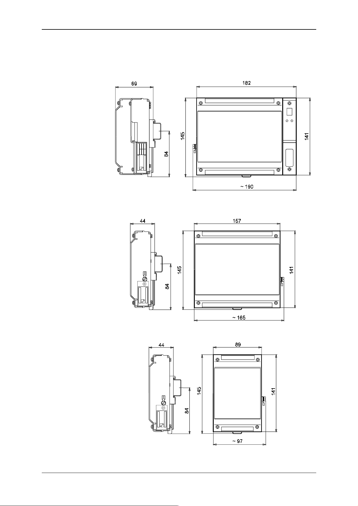
Tecomat TC600
9.3 The Mounting
&' ()$ '
(idt EN 50022:1977). Outside proporti ons of the P LC BM, EM and E M/2 are
apparent fr om Figs. 9.1, 9.2 and 9.3.
Fig. 9.1 Mechanic proport ions of PLC BM of the TC600 series
Fig. 9.2 Mechanic proport ions of PLC EM of the TC600 series
Fig. 9.3 Mechanic proport ions of PLC EM/2 of the TC600 series
TXV 138 08.02 34
Page 35
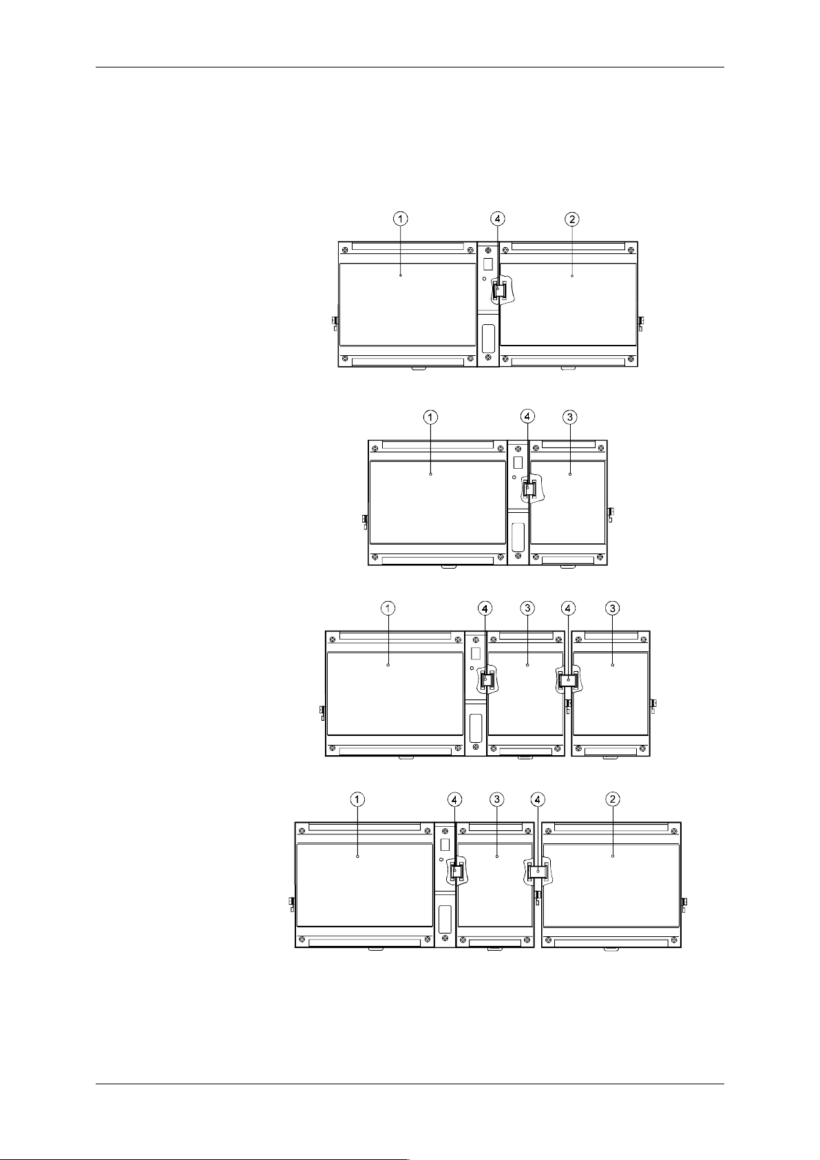
Technical equipment of TC600 PLC
EM and EM/2 are placed always on the right side from the BM. EM
(EM/2) are connected mutually as well as with the BM by a band cable
which is part of the EM (EM/2). Cable socket is connected into a socket plug
on the right side of the BM (EM/2). Af ter connecting the cabl e, modules on
the bar are moved to t heir close proxi mity. Possible ways of extensi on are
given in Fi gs. 9.4 to 9.7.
Fig. 9.4 BM extension by one E M
Fig. 9.5 BM extension by one E M /2
Fig. 9.6 BM extension by two EM/2
Fig. 9.7 BM extension by one E M /2 and one EM
1 - Basic module (BM)
2 - Extensi on module (EM)
3 - Half extension module (EM/2)
4 - Connection c able
35 TXV 138 08.02
Page 36
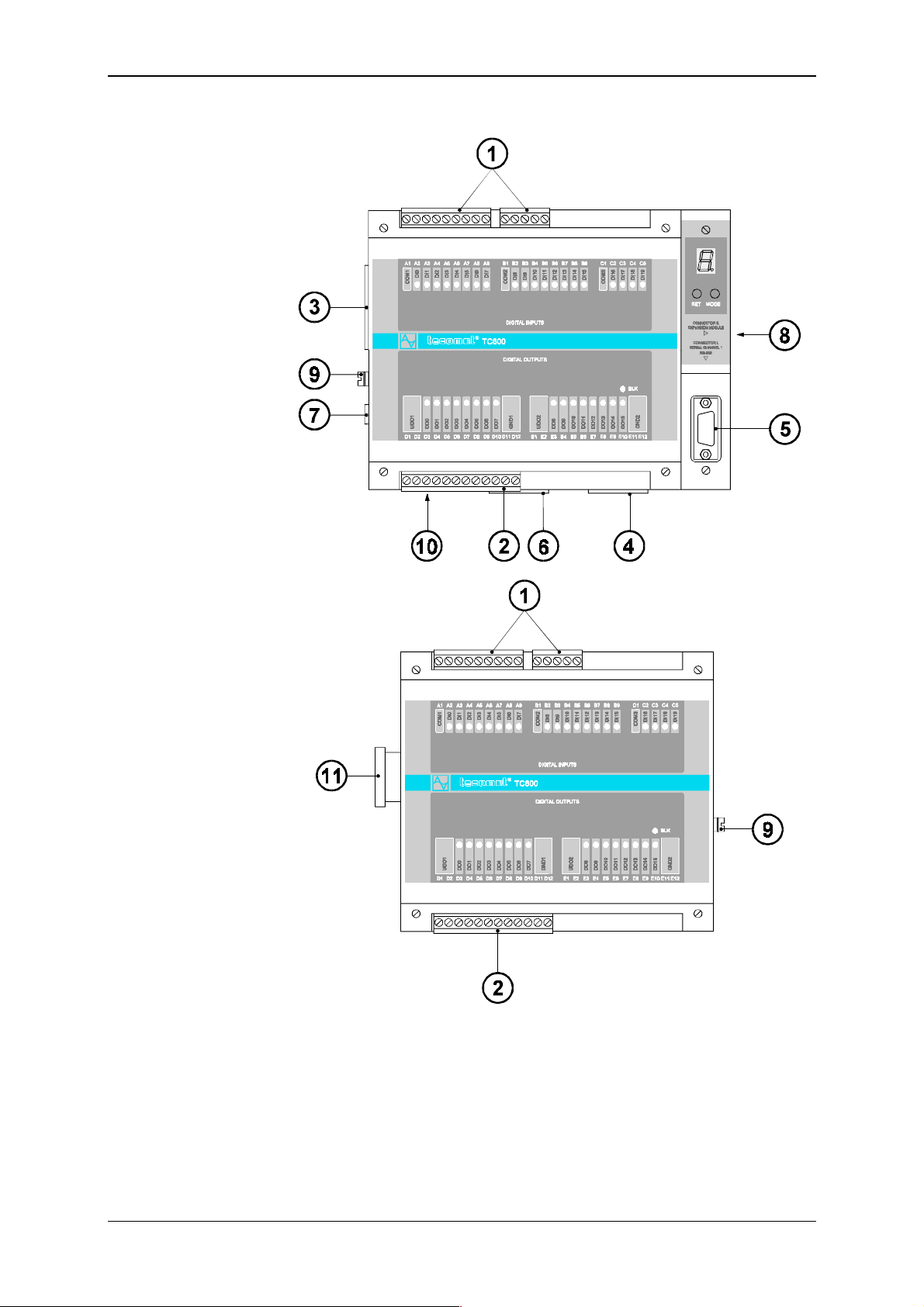
Tecomat TC600
9.4 Arrangement of Connecting of Terminal Boards
terminal boards
1
terminal board D of binary transistor outputs
2
terminal board P of optional analog outputs or CH3
3
terminal board K of optional CH1 interface
4
socket L of CH1 interface RS-232
5
terminal board N of optional CH2 interface
6
terminal board M of the PLC power supply
7
socket plug R for connection of the EM
8
connector for connection of the protective conductor
9
fuse of the power supply converter
10
sock et for con nection to the BM
11
of binary inputs
A, B
Fig. 9.8 Arrangement of Connecting Terminal Boards of TC601 BM and
TC621 EM (below)
TXV 138 08.02 36
Page 37
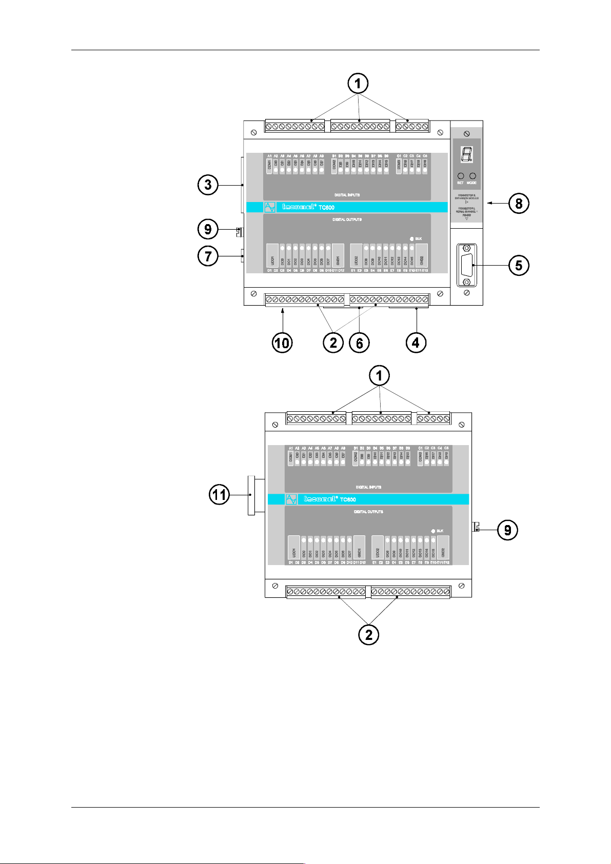
Technical equipment of TC600 PLC
terminal boards
1
terminal board
2
terminal board P of optional analog outputs or CH3
3
terminal board K of optional CH1 interface
4
socket L of CH1 interface RS-232
5
terminal board N of optional CH2 interface
6
terminal board M of the PLC power supply
7
socket plug R for connection of the EM
8
connector for connection of the protective conductor
9
fuse of the power supply converter
10
sock et for con nection to the BM
11
s D, E
of binary inputs
A, B, C
of binary transistor outputs
Fig. 9.9 Arrangem ent of Connecting Ter m inal B oar ds of TC602 BM (above)
and TC622 EM (below)
37 TXV 138 08.02
Page 38
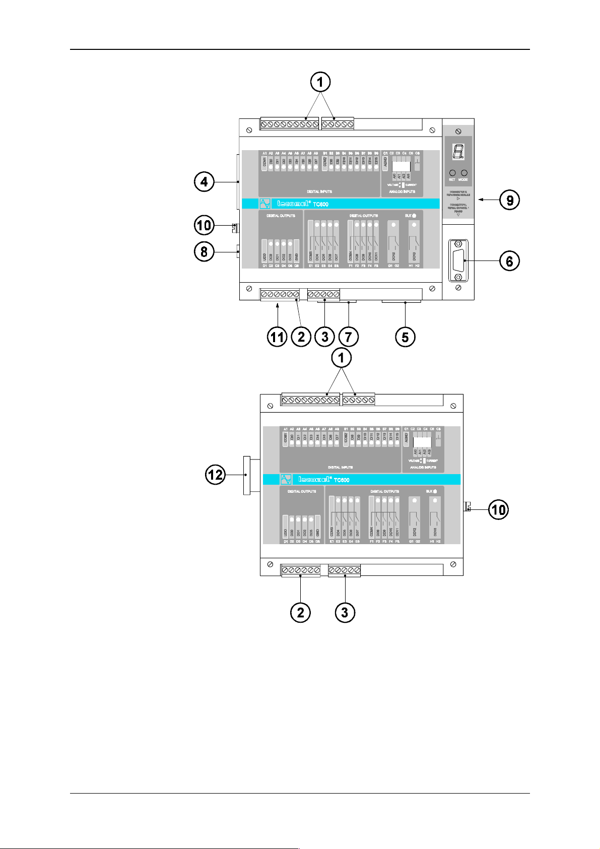
Tecomat TC600
terminal boards
1
terminal board D of binary transistor outputs
2
terminal board E of binary relay outputs
3
terminal board P of optional analog outputs or CH3
4
terminal board K of optional CH1 interface
5
socket L of CH1 interface RS-232
6
terminal board N of optional CH2 interface
7
terminal board M of the PLC power supply
8
socket plug R for connection of the EM
9
connector for connection of the protective conductor
10
fuse of the power supply converter
11
sock et for con nection to the BM
12
of binary inputs
A, B
Fig. 9.10 Arrangement of Connection Term inal B oar ds of TC603 BM (above)
and TC623 EM (below)
TXV 138 08.02 38
Page 39
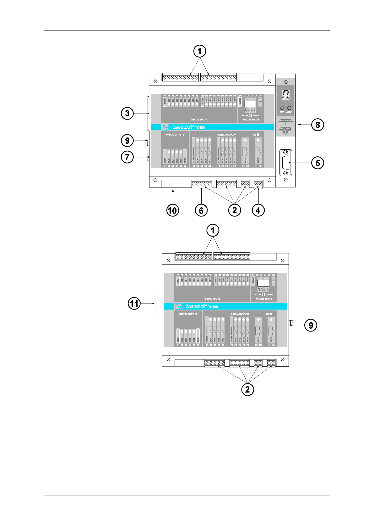
Technical equipment of TC600 PLC
terminal boards
1
terminal boards
2
terminal board P of optional analog outputs or CH3
3
terminal board K of optional CH1 interface
4
socket L of CH1 interface RS-232
5
terminal board N of optional CH2 interface
6
terminal board M of the PLC power supply
7
socket plug R for connection of the EM
8
connector for connection of the protective conductor
9
fuse of the power supply converter
10
sock et for con nection to the BM
11
of binary inputs
A, B
E, F, G, H
of binary relay outputs
Fig. 9.11 Arrangement of Connection Term inal B oar ds of TC604 BM (above)
and TC624 EM (below)
39 TXV 138 08.02
Page 40
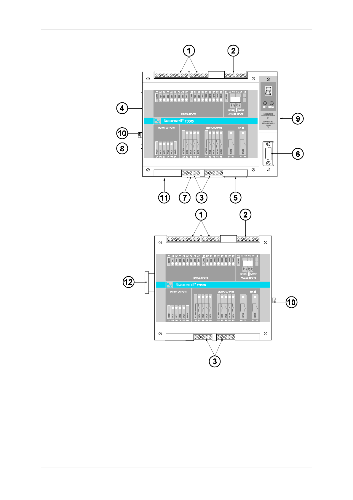
Tecomat TC600
terminal boards
1
terminal board C of analog inputs
2
terminal boards
3
terminal board P of optional analog outputs or CH3
4
terminal board K of optional CH1 interface
5
socket L of CH1 interface RS-232
6
terminal board N of optional CH2 interface
7
terminal board M of the PLC power supply
8
socket plug R for connection of the EM
9
connector for connection of the protective conductor
10
fuse of the power supply converter
11
sock et for con nection to the BM
12
of binary inputs
A, B
of binary relay outputs
E, F
Fig. 9.12 Arrangement of Connection Term inal B oar ds of TC605 BM (above)
and TC625 EM (below)
TXV 138 08.02 40
Page 41
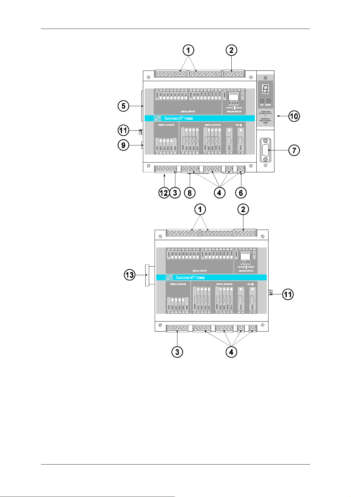
Technical equipment of TC600 PLC
terminal boards
1
terminal board C of analog inputs
2
terminal board D of binary transistor outputs
3
terminal boards
4
terminal board P of optional analog outputs of CH3
5
terminal board K of optional CH1 interface
6
socket L of CH1 interface RS-232
7
terminal board N of optional CH2 interface
8
terminal board M of the PLC power supply
9
terminal board R for connection of the EM
10
connector for connection of the protective conductor
11
fuse of the power supply converter
12
sock et for con nection to the BM
13
of binary inputs
A, B
E, F, G, H
of binary relay outputs
Fig. 9.13 Arrangement of Connection Term inal B oar ds of TC606 BM (above)
and TC626 (below)
41 TXV 138 08.02
Page 42
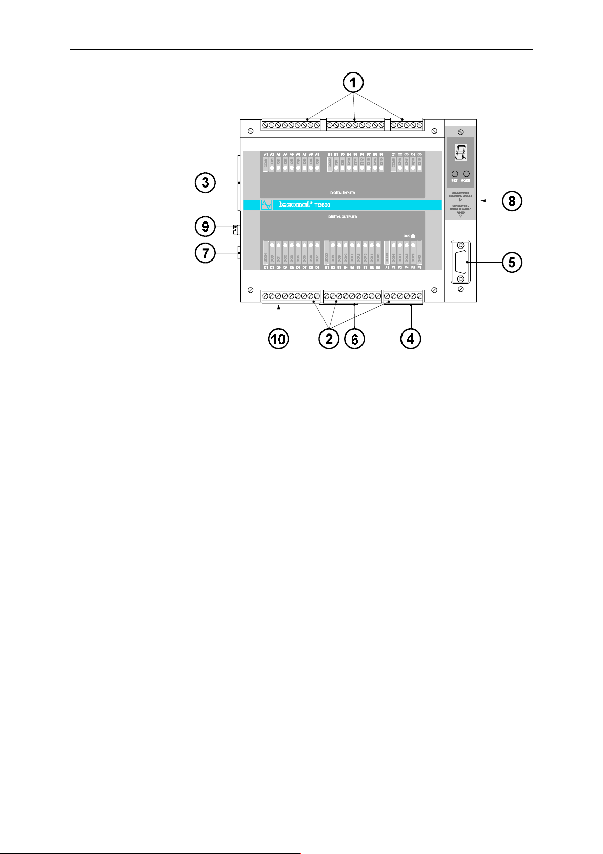
Tecomat TC600
terminal boards
1
terminal boards
2
terminal board P of optional analog outputs or CH3
3
terminal board K of optional CH1 interface
4
socket L of CH1 interface RS-232
5
terminal board N of optional CH2 interface
6
terminal board M of the PLC power supply
7
socket plug R for connection of the EM
8
connector for connection of the protective conductor
9
fuse of the power supply converter
10
of binary inputs
A, B, C
of binary transistor outputs
D, E, F
Fig. 9.14 Arrangement of Connection Term inal B oar ds of TC607 BM
TXV 138 08.02 42
Page 43
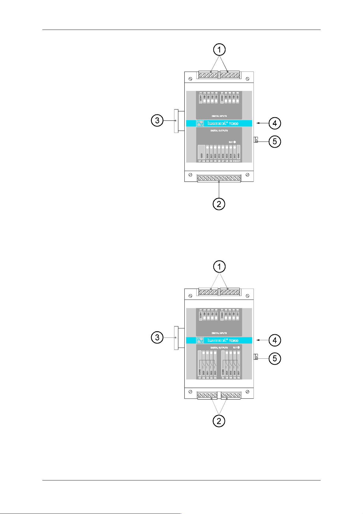
Technical equipment of TC600 PLC
terminal boards
1
terminal board C of binary transistor outputs
2
sock et for con nection to the BM
3
socket plug for connection of the EM or EM/2
4
connector for connection of the protective conductor
5
of binary inputs
A, B
Fig. 9.15 Arrangement of Connection Term inal B oar ds of TC631 EM/2
terminal boards
1
terminal board C of binary relay outputs
2
sock et for con nection to the BM
3
socket plug for connection of the EM or EM/2
4
connector for connection of the protective conductor
5
of binary inputs
A, B
Fig. 9.16 Arrangement of Connection Term inal B oar ds of TC632 EM/2
43 TXV 138 08.02
Page 44
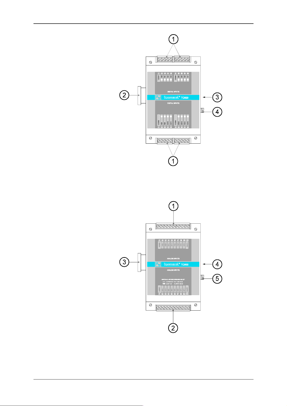
Tecomat TC600
terminal boards
1
sock et for con nection to the BM
2
socket plug for connection of the EM or EM/2
3
connector for connection of the protective conductor
4
A, B, C, D
of binary inputs
Fig. 9.17 Arrangement of Connection Term inal B oar ds of TC633 EM/2
terminal board A of analog inputs AI0 to AI3
1
terminal board
2
sock et for con nection to the BM
3
socket plug for connection of the EM or EM/2
4
connector for connection of the protective conductor
5
of analog inputs AI4 to AI7
B
Fig. 9.18 Arrangement of Connection Term inal B oar ds of TC634 EM
TXV 138 08.02 44
Page 45
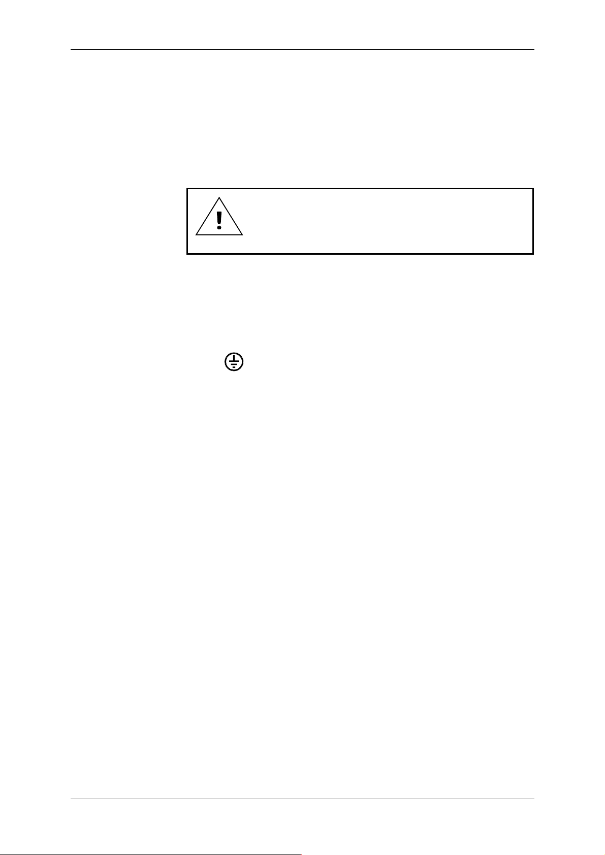
Technical equipment of TC600 PLC
9.5 Connection of the PLC Inputs and Outputs
Wi th the exception of the protectiv e grounding connector and the CH1
RS-232 interf ace, PLC inputs and outputs are connected using rem ovable
termi nal boards which are inserted into t he appropriate socket plugs of i nputs and outputs. The screw part of the terminal board is constructed for
connection of a full conductor with cross section up to 1.5 mm
with cross section up to 1 mm
of the f ul l conduct or i s 0.2 m m
2
. The mini mum recom mended cross section
2
, of t he wire 0.5 m m2. Term inal boards are a
part of the PLC additional package.
Connection ter minal boar ds are not pr otected against exchange by any coding element, c hec k the connection before putting them into operat ion!
9.5.1 Connection of the Protective Connector
The PLC protective connector must be interconnected with the inside
protective connector of the case. Interconnection m ust meet requirements
* +, IEC 364-5-54:1980). From t he vi ewpoint of disturbances, in cases with the m etal mounti ng board it is suitabl e to connect
the protecti ve term inal board with t he mounting board by the shortest connection possible. The protect iv e c onnec tor is mark ed with the label 417-IEC-
2
or a wire
PLC power supply
can also be used for
supplying of binary
inputs
5019-a
.
9.5.2 PLC Power Supply
Power supply of the PLC, input and output ci rcuits, m ust be in the ov er - 33 0420 (eqv IEC 664:1980,
IEC 664A:1981).
The power supply must m eet c ondit i ons of t he SELV supply acc ordi ng t o
++,$+++.//01
Between the primary and secondary winding of the transformer, a Cu
shielding f oil must be wound up, connec ted with t he inside prot ectiv e t ermi nal board of the case or the winding must be arranged spati ally in such a
way so that the mutual capacity between the windings is minimized. It is
suitable to insert switches int o the supply lead whic h m ake work on program
debugging, m aintenance and possible repairs easier.
The power supply v oltage of the P LC, 24 V~ ±20%, 50 - 60 Hz ±5% or
24 V- ±20 %, is connected to c onnectors M1 and M2 of t he term inal boar d
marked as POW E R INPUT. In connect ion of the di rect- current supply, v oltage polarit y does not matter. P ermanent ex ceeding of the tol erance upper
lim it m ay cause breaki ng of the v olt age protecti v e elem ent of the PLC converter. For dimensioning of the supply, it is necessary to consider the
maxi mum input of 13 W (20 VA), which also contai ns input of coils of the
relay of binary relay outputs.
Switches of input circuits m ay be supplied from the same power supply
as the BM internal converter. Input of the closed binary input is typically
0.25 W (0.25 VA). For connection of the binary inputs supply see item 9.5.3.
Circuit s closed by binary output s must be supplied f rom an independent
power supply or at least f rom an i ndependent transf orm er winding. The supply must be dim ensioned accordi ng to the conc rete input of t he loads. Input
of the output transistor cir cuit is ty picall y 0.2 W for cur rent of 1 A. For connection of the binary outputs power supply see items 9.5.4 and 9.5.5.
45 TXV 138 08.02
Page 46
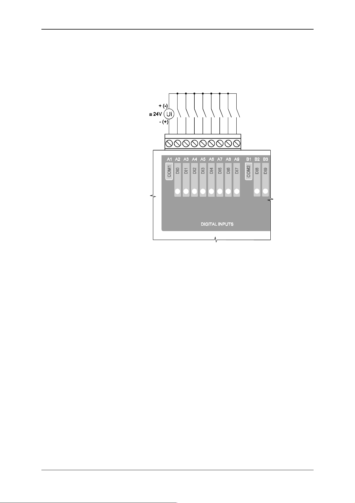
Tecomat TC600
9.5.3 Connection of Binary Inputs
PLC binary i nputs are led out to connec tors of terminal boar ds marked as
DIGITAL INPUTS. Input switches are connected between the input connector and the com mon connector of t he group. In Fig. 9.17, scheme of connection of switches and the power supply to one group of i nputs of T C601 to
TC607 (TC621 to T C626) is indicat ed.
Fig. 9.17 Example of connection of s witches to binary input s of the PLC of
the TC600 series
Supply v olt age of a gr oup of switc hes may be connect ed in arbi trary polarit y , within the gr oup individual inputs must be pol ed identically.
For fit ting and marking of terminal boards of binary inputs of indivi dual
PLC types see Article 9.4.
TXV 138 08.02 46
Page 47
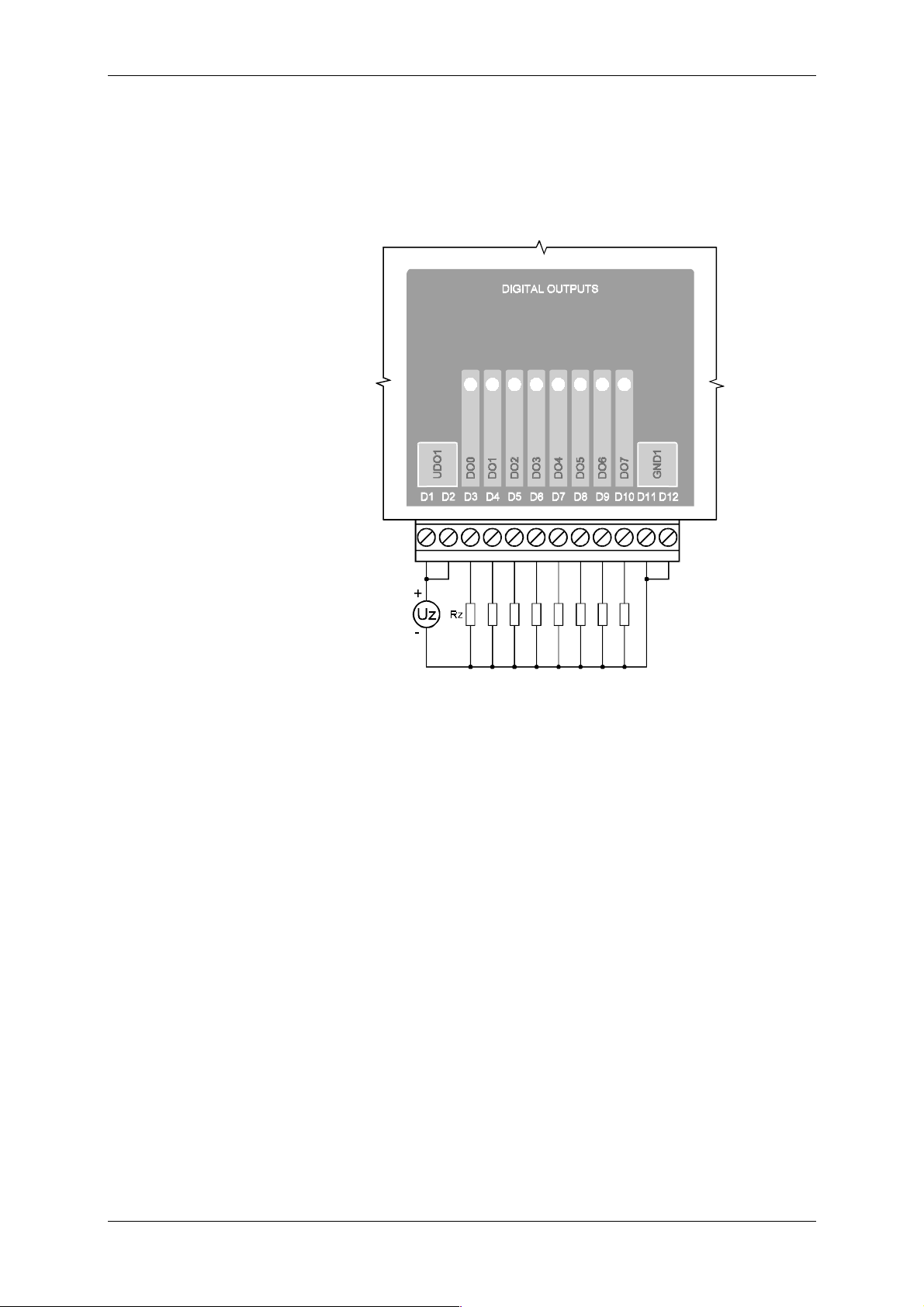
Technical equipment of TC600 PLC
9.5.4 Connection of Binary Transistor Out puts
Transistor switches of binary outputs are led out to connectors of t erminal boards marked as DIGITAL OUTPUTS. In Fig. 9.18, scheme of connection of l oads and the power supply to one of t he groups of output s of TC601
(TC621), TC602 (TC622) is indicated. Transistor outputs of other types of
the series are connected in the similar way as well.
Fig. 9.18 E xample of connection of loads to binary transist or outputs of t he
PLC of the TC600 ser ies
For fi tting and m arking of term inal boards of binary transi stor outputs of
individual PLC types see Artic le 9.4.
47 TXV 138 08.02
Page 48
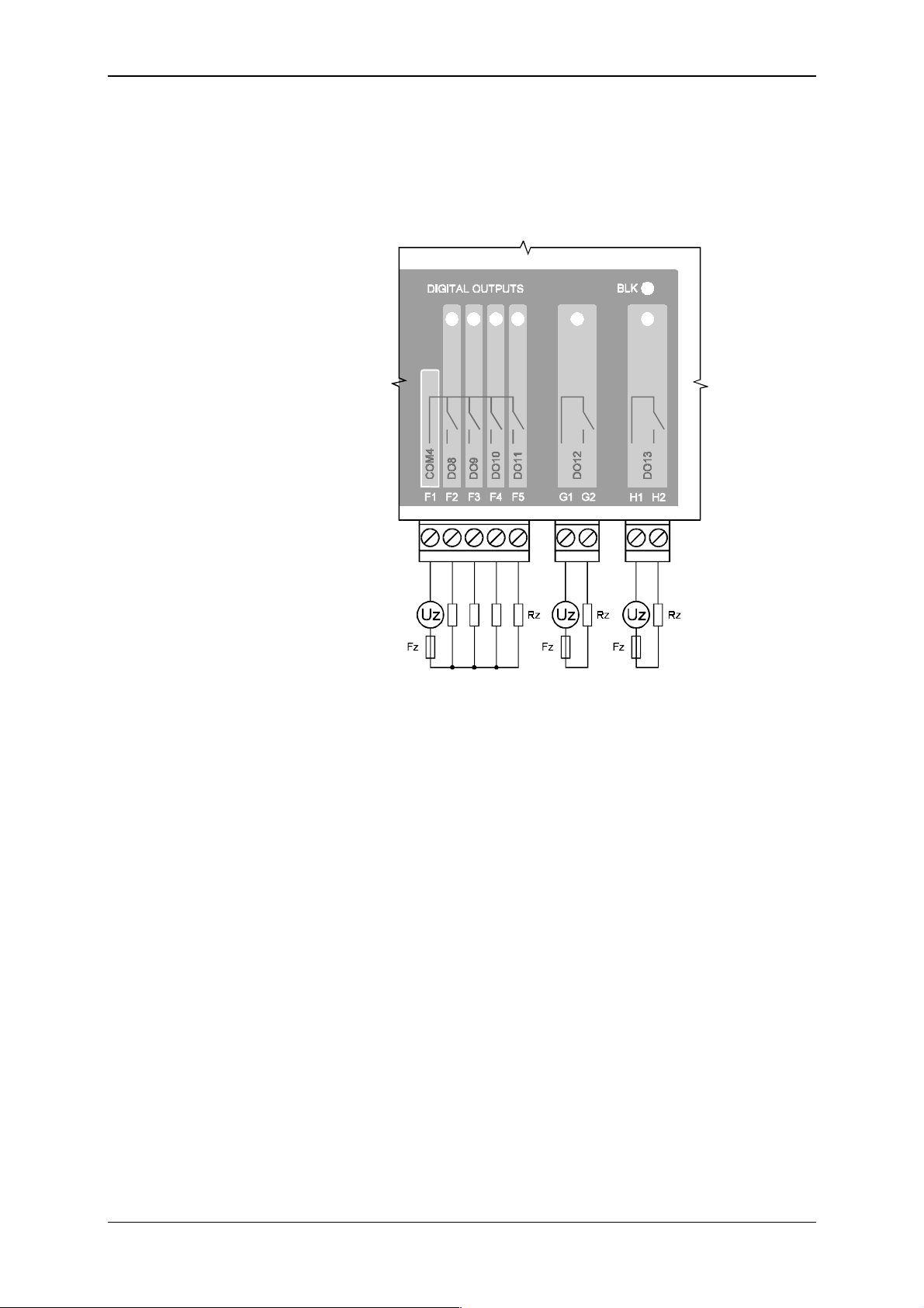
Tecomat TC600
9.5.5 Connection of Binary Relay Outputs
Contacts of the relay of binary outputs are led out to terminal boards
marked as DIGITAL OUTPUTS. Fig. 9.19 shows scheme of connection of
loads to relay c ontacts led out to the t ermi nal board i n the group, and of i ndependently led out contact of TC604 (TC624), T C606 (TC626). Rel ay outputs of other types of the seri es are connec ted simi larly.
Fig. 9.19 Example of connec tion of loads to binar y relay out puts of t he PLC
of TC600 series
For fit ting and m arki ng of term inal boar ds of binar y relay out puts of i ndividual PLC types see Article 9.4.
TXV 138 08.02 48
Page 49
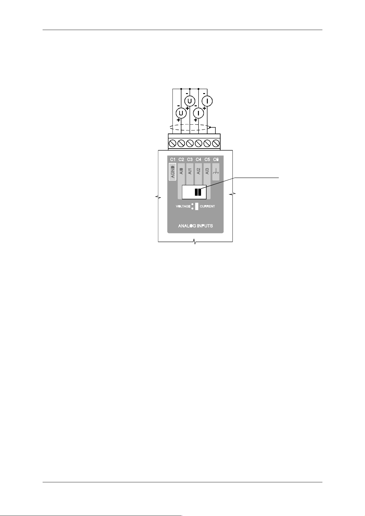
Technical equipment of TC600 PLC
9.5.6 Connection of Analog Inputs of TC605, TC606, T C625, TC626
Analog input s are led out to c onnectors of the term inal board mar ked as
ANALOG INP UTS. In Fig. 9.20, scheme of connection of current and vol tage signal supplies to analog inputs of TC605 (T C625), TC606 (TC626) is
indicat ed.
Configuration
jumpers
Type of the analog
input is set by a
jumper
Fig. 9.20 Example of connection of current and voltage signals to analog
inputs of the PLC of the TC600 series
Connection of a r elevant j umper modi fying t he voltage i nput to the current one, m ust correspond with the cur rent signal supply connect ed to the
input. Disconnected jumper corresponds with the v oltage input, connected
jumper corresponds with the current i nput. Jumpers are accessibl e through
openings in the regulator cover. Setting of jumpers for the required input
type is shown on the label close to the jumpers.
Connector C6 connected with the controller cover, is intended for connection of the shielding of lead in conductors. If the shielding is
connected with the dev ic e fram e in another pl ace, for ex ampl e to the i nput
termi nal board of t he distr ibut i on board, i t is no m ore connect ed wit h the C6
connector. Ex amples of the instal lation reali zation in the di stributi on board
are contained in the handbook
Design of Tecomat Programmable Logic
Controllers, T X V 001 08.01.
For fitti ng of terminal boar ds of analog inputs of individual P LC types see
Article 9.4.
9.5.7 Connection of TC634 Analog Inputs
Analog inputs of the T C634 module and the inter nal current supply are
led out to terminal boards marked as ANALOG INPUTS. Fig. 9.21 shows
scheme of connection of current and vol tage signal supplies to analog inputs AI0-AI3, Fig. 9.22 shows scheme of connect ion of resistance temper ature scanners to inputs AI 4- A I7.
49 TXV 138 08.02
Page 50
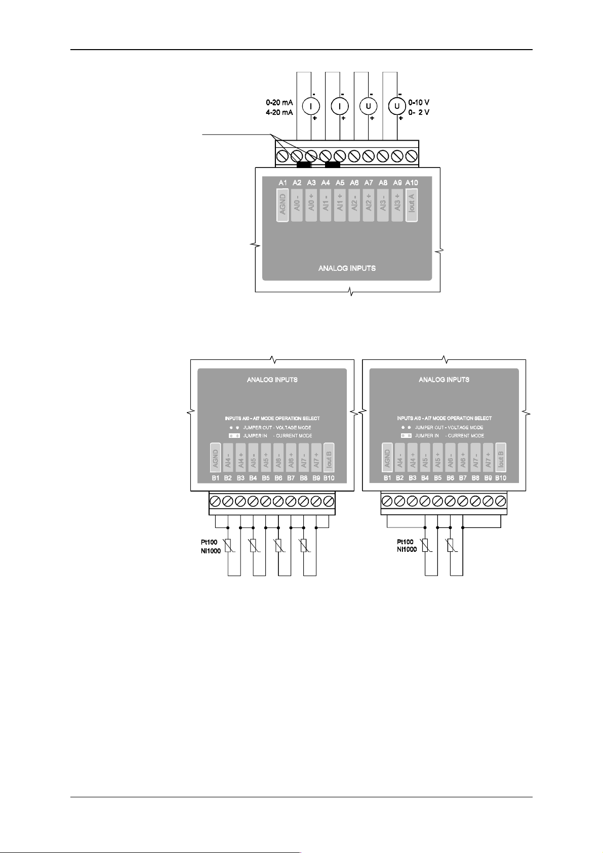
Tecomat TC600
Configuration jumpers
Fig. 9.21 Exam ple of connection of current and voltage s ignals to t he TC634
analog inputs
Fig. 9.22 Example of connection of r esistance temperature s canners to t he
TC634 analog inputs
Type of the analog
input is set by a
jumper
Ever y input must be set indiv iduall y by the jumper for the direc t-current
vol tage or current signal supply. Jum pers are placed above cor responding
couples of input connectors, and are accessible through openings in the
controller cover. Disconnected jumper corresponds with the voltage input,
connected jumper corresponds with the curr ent input. For passive resistance
temperature scanners, voltage input type is set (the jumper is disconnected).
TXV 138 08.02 50
Page 51
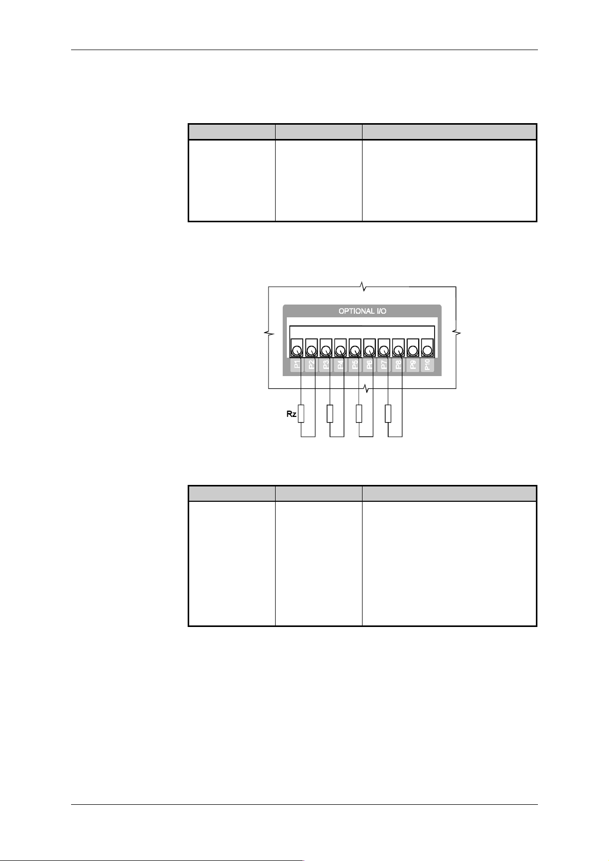
Technical equipment of TC600 PLC
9.5.8 Connection of Analog Outputs
Optionally fitted BM analog outputs of TC601 to TC607 are led out to
connectors P1 to P10 of the terminal boar d marked as OPTIONAL I/O.
Lead out of analog
outputs of t he OT-13
piggyback
Connector Signal Note
P1 AO0 analog output 0
P3 AO1 analog output 1
P5 AO2 analog output 2
P7 AO3 analog output 3
P2, P4, P6, P8,
P9, P10
In Fig. 9.23, scheme of connection of loads to the OT-13 piggyback
analog outputs is i ndicated.
AGND common analog ground
Lead out of analog
outputs of t he OT-14
piggyback
Fig. 9.23 Connection of loads to the OT- 13 piggy bac k analog outputs
Connector Signal Note
P1 AO0 analog output 0
P2 AO4 analog output 4
P3 AO1 analog output 1
P4 AO5 analog output 5
P5 AO2 analog output 2
P6 AO6 analog output 6
P7 AO3 analog output 3
P8 AO7 analog output 7
P9, P10 AGND common analog ground
51 TXV 138 08.02
Page 52
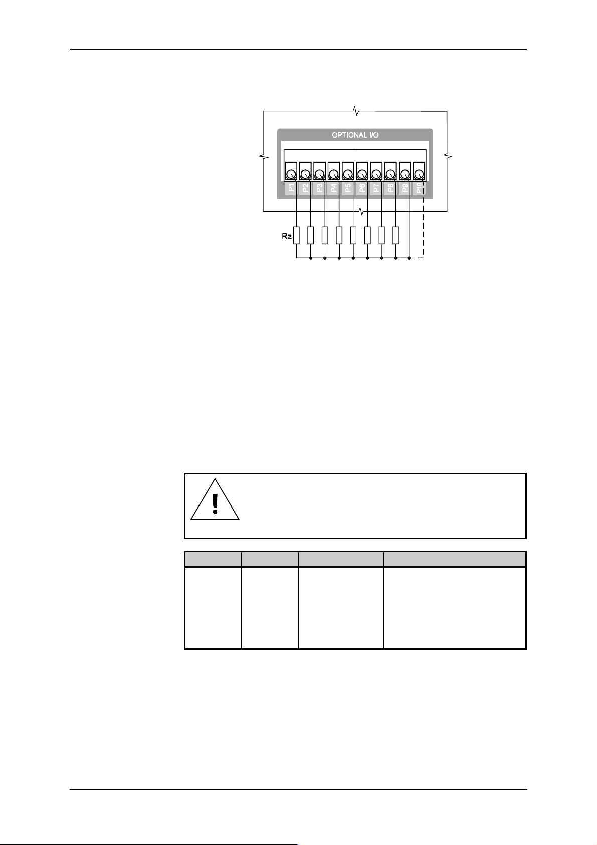
Tecomat TC600
In Fig. 9.24, scheme of connection of loads to the OT-14 piggyback
analog outputs is i ndicated.
Fig. 9.24 Connection of loads to the OT- 14 piggy bac k analog outputs
Exam ples of the installat ion reali zation i n the distribut ion board are contained in t he handbook
Design of Tecomat Program mable Logic Contr ollers,
TXV 001 08.02.
For fi tting of t erminal boards of anal og outputs of indi vidual PLC types
see Articl e 9.4.
CH1 RS-232 interface
Signals of the CH1
RS-232 interface
9.5.9 Connection of the CH1 Interface
Interf ace RS- 232 of CH1 i s designed especial ly f or connect i on of a com puter of the PC class performing the function of a programming device.
Binding circuits of the interface are led out to the 9-pole socket Dsub
(CONNECTOR L) m arked as SERI AL CHANNE L 1/RS- 232. T he connect ion
is realiz ed by the cabl e TXK 646 51.06 ended on the PC si de by the 9- pole
Dsub socket.
If t he optional CH1 interf ac e is fitted, by connecting the
cable TXK 646 51.06, si gnals of CH1 will be disconnected
automaticall y from the optional interface.
Lead out Signal Signal type Use
L2 RxD input data signal
L3 TxD output data signal
L5 GND signal gr ound
L7 RTS output controll ing signal
L8 CTS i nput controlling signal
1)
1)
L9 232DIS input CH1 interf ac e switc h
1)
Use of the signal is described in the handbook
Tecomat Progr ammable Logic Controllers, T XV 001 06.01.
Serial Communication of
Still level of
the signal corr esponds with the val ue of logical 1.
TXV 138 08.02 52
Page 53
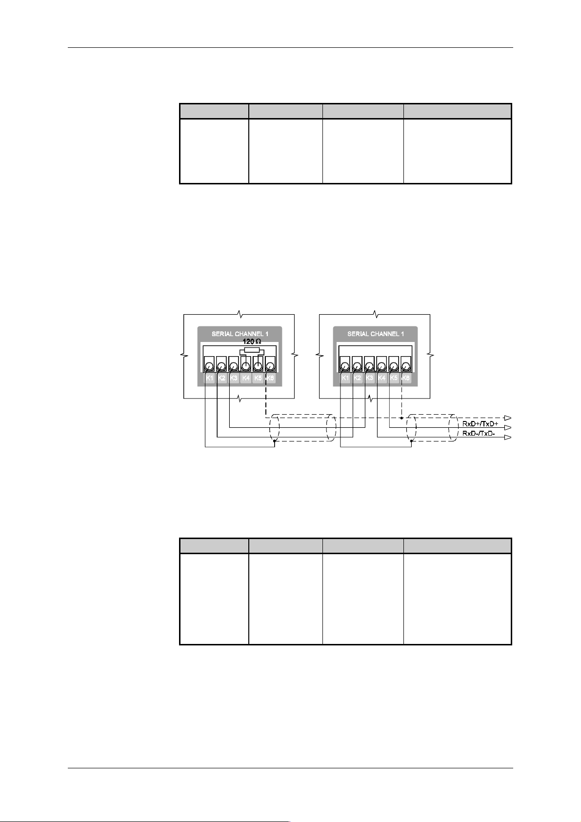
Technical equipment of TC600 PLC
Optional CH1 RS-485
interface
Lead out of binding
circuits of piggy bac k s
MR-04, MR-09 of
CH1
Binding ci rc uit s of the i nter f ace are l ed out to connect ors K 1 t o K6 of t he
terminal board m ar k ed as SERIAL CHANNEL 1.
Connector Signal Signal type Use
K1 frame connection of the
shielding
K2, K4 RxD-/TxD- input /output data si gnal
K3, K5 RxD+ /TxD+ input/output data signal
K6 GND signal ground
Interconnect ion i s real iz ed by a coupl e of twisted shiel ded conduct ors. In
general, it holds that for higher com municat ion speeds and greater lengths
of cabl es, it is necessary to use higher c ross section of conduct ors. For reduction of reflect i ons, the l i ne is i m pedance-adj usted by t erm i nators on both
ends of the line. In some cases, it is necessary to interconnect signal
grounds to balance their pot entials. I n Fig. 9. 25, scheme of interconnect ion
of the RS- 485 interface at the marginal and internal equipment of the network is indicat ed.
Internal ne twork equipm entMarginal network equipment
Optional CH1 RS-422
interface
Lead out of binding
circuits of the
piggyback MR-17 of
CH1
Fig. 9.25 Interconnection of two CH1 interfaces RS-485 of the PLC of
TC600 series
Binding ci rc uit s of the i nter f ace are l ed out to connect ors K 1 t o K6 of t he
terminal board m ar k ed as SERIAL CHANNEL 1.
Connector Signal Signal type Use
K1 frame connection of the
shielding
K2 TxD- output data signal
K3 TxD+ output data signal
K4 RxD- input data signal
K5 RxD+ input data signal
K6 GND signal ground
Interconnect ion is realized by two couples of shi elded twisted conduc tors.
In general, it holds that for higher communication speeds and greater
lengths of cables, it i s necessary to use greater cross section of the conductors. For reduction of reflect ions, the line i s impedance-adjusted by terminat ors on the side of the recei vers. In som e cases, it is necessary to interconnect the signal grounds to balance the potentials. In Fig. 9.26,
scheme of interconnect ion of t wo RS-422 interf ac es i s i ndicated.
53 TXV 138 08.02
Page 54
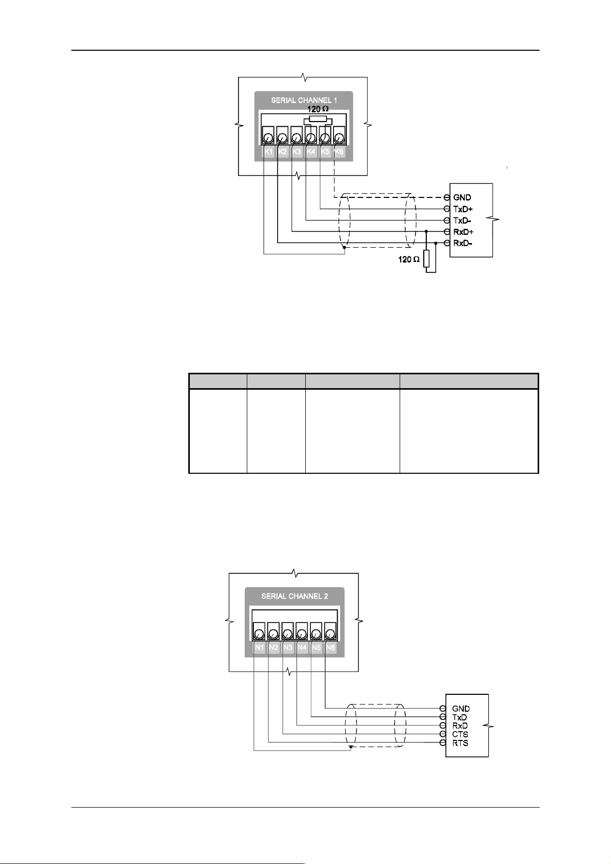
Tecomat TC600
Optional CH2 RS-232
interface
Interface of
the connect ed
device
Fig. 9.26 Interconnect ion of CH1 interfaces RS - 422 of the PLC of TC600 se-
ries
9.5.10 Connection of the CH2 Interface
Binding ci rc uit s of the i nter f ace are l ed out to connec tors N1 to N6 of t he
terminal board m ar k ed as SERIAL CHANNEL 2.
Lead out of binding
circuits of the
piggyback MR-02 of
CH2
Lead out Signal Signal type Use
N1 frame connection of the shiel ding
N2 CTS i nput controlling signal
N3 RTS output controlling signal
1)
1)
N4 TxD output data signal
N5 RxD input data signal
N6 GND signal ground
1)
Use of the signal is described in the handbook
Tecomat Progr ammable Logic Controllers, T XV 001 06.02
Serial Communication of
. Still level of
the signal corr esponds with the val ue of logical 1.
In Fig. 9.27, five-conductor interconnection with the possibility of CTS
signal detect ion is shown.
Inte rface of
the connected
device
Fig. 9.27 Five-conductor interconnection of the CH2 interface RS-232 of
the PLC of TC600 ser ies
TXV 138 08.02 54
Page 55
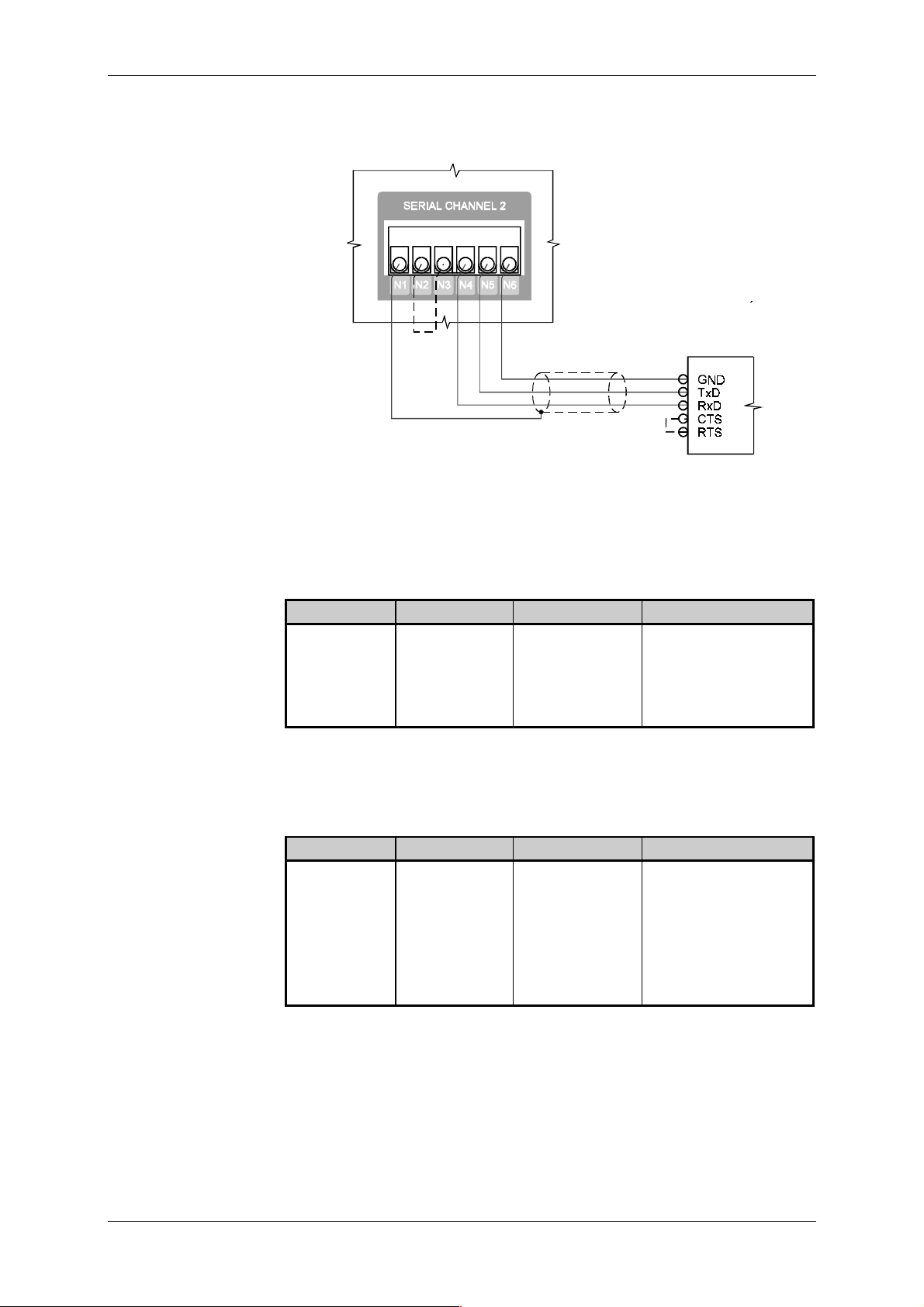
Technical equipment of TC600 PLC
Fig. 9. 28 shows three-conductor interconnec tion of data binding c ircuit s.
The dashed line i ndicates for mation of the RTS - CTS loop.
Interface of
the connected
device
Fig. 9.28 Three-conductor interc onnection of the CH2 interface RS- 232 of
the PLC of TC600 ser ies
Optional CH2 RS-485
interface
Lead out of binding
circuits of piggy bac k s
MR-04, MR-09 of
CH2
Optional CH2 RS-422
interface
Lead out of binding
circuits of the
piggyback MR-17 of
CH2
Binding ci rc uit s of the i nter f ace are l ed out to connec tors N1 to N6 of t he
terminal board m ar k ed as SERIAL CHANNEL 2.
Connector Signal Signal type Use
N1 frame connection of the
shielding
N2, N4 RxD-/T xD- input/output data signal
N3, N5 RxD+/TxD+ input/output data signal
N6 GND signal ground
Interconnect ion is realized in the way described under item 9.5.9.
Binding ci rc uit s of the i nter f ace are l ed out to connec tors N1 to N6 of t he
terminal board m ar k ed as SERIAL CHANNEL 2.
Connector Signal Signal type Use
N1 frame connection of the
shielding
N2 TxD- output data si gnal
N3 TxD+ output data si gnal
N4 RxD- input data signal
N5 RxD+ input data signal
N6 GND signal ground
Interconnect ion is realized in the way described under item 9.5.9.
55 TXV 138 08.02
Page 56
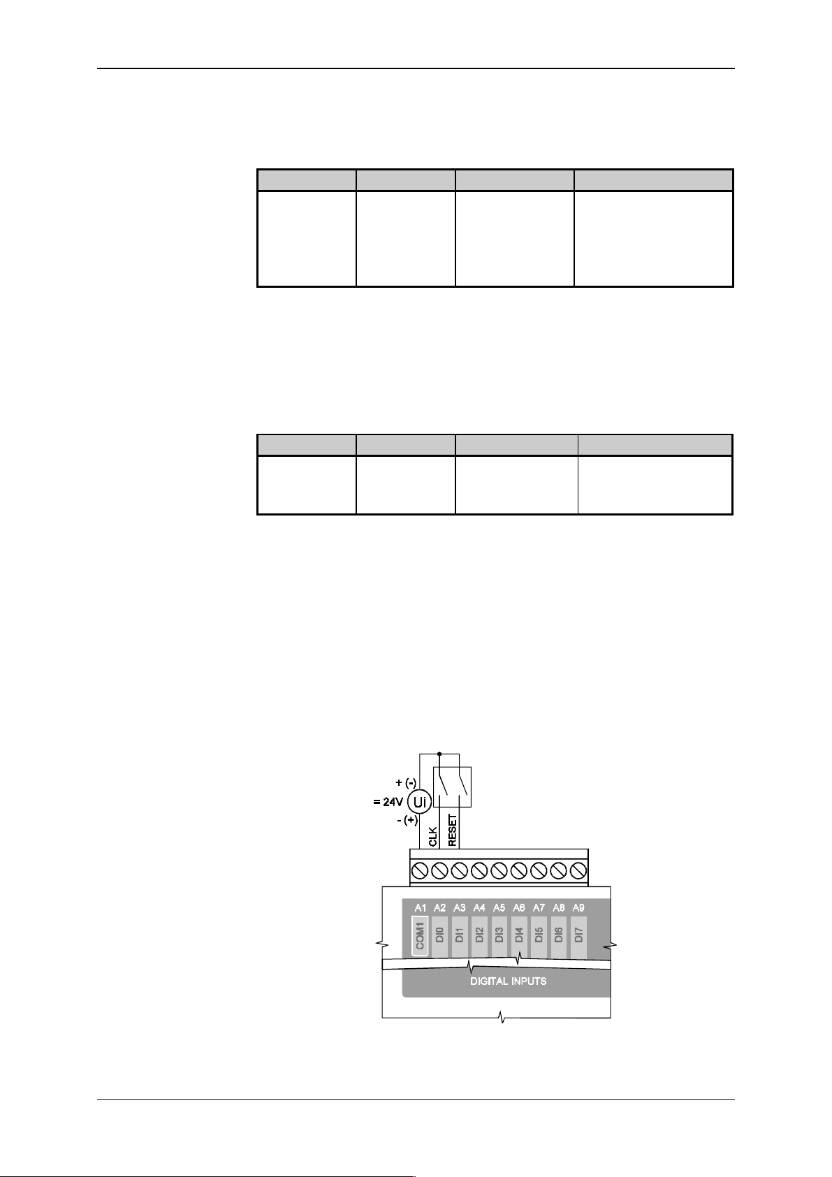
Tecomat TC600
CH3 RS-232 interface
9.5.11 Connection of the CH3 Interface
Binding ci rc uit s of the i nter f ace are l ed out to connect ors P 1 t o P5 of t he
terminal board m ar k ed as OP TIONAL I/O.
Lead out of binding
circuits of the piggyback MR-15 of CH3
CH3 RS-485 interface
Lead out of binding
circuits of the piggyback MR-14 of CH3
Lead out Signal Signal type Use
P1 TxD output data signal
P2 RTS output controll ing signal
P3 RxD input data signal
P4 CTS input controlling signal
P5 GND signal ground
1)
Use of the signal is described in the handbook
Tecomat Programmable Logic Controllers, T XV 001 06.02
Serial Communication of
. Still level of the
signal corresponds with the value logical 1.
Interconnect ion is realized in the way described under item 9.5.10.
Binding ci rcuits of the i nterface are led out to connectors P6 to P10 of
the term inal board marked as OPTIONAL I/O.
Connector Signal Signal type Use
P6, P8 RxD+ /TxD+ input/output data signal
P7, P9 RxD-/TxD- input/ output data si gnal
P10 GND signal gr ound
Interconnect ion is realized in the way described under item 9.5.9.
9.5.12 Connection of Interrupt Inputs
Interrupt input s are connected identic ally as comm on binary inputs (see
item 9.5.3).
1)
1)
9.5.13 Connection of the Type 3 Counter
Source of counted ev ents and the controlling signal are connected between the comm on connector A1 (CO M1) and connectors A2 ( DI0) and A3
(DI1) in the way illustrated in the scheme in Fig. 9.29. In the case that the
RESET input is not used, it must be servi ced by connection to v olt age corresponding with log. 1.
Fig. 9.29 Connection of t he type 3 counter of the PLC of TC600 series
TXV 138 08.02 56
Page 57
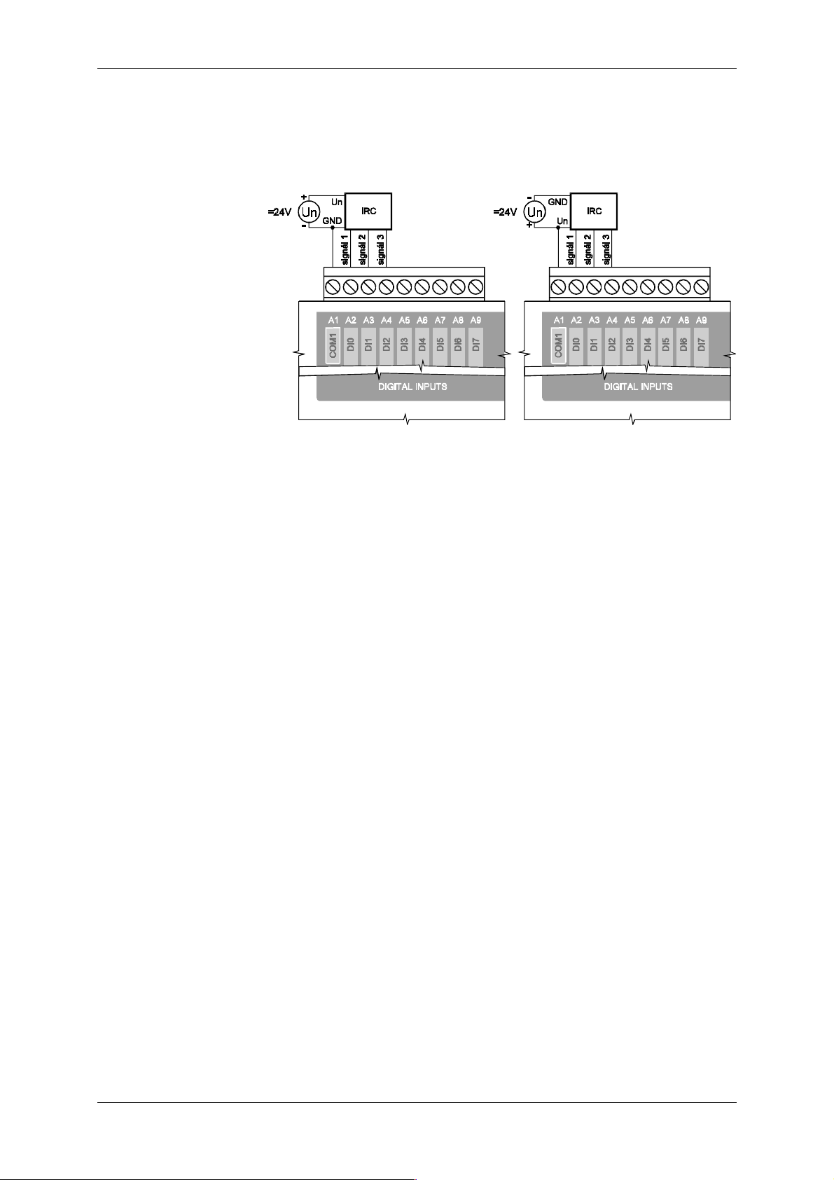
Technical equipment of TC600 PLC
9.5.14 Incremental E ncoder Connection
Incremental encoder is connected between the common connector A1
(COM1) and connectors A2 (DI0) to A4 (DI2) in the way illustrated in the
scheme in Fig. 9.30.
signal 1 - direc t output of trace 1
signal 2 - direc t output of trace 2
signal 3 - direc t output of the zero pulse
Fig. 9.30 Connection of the incremental encoder with outputs with the open
PNP collector (on t he left) and NPN collector (on the right) to t he
PLC of TC600 series
9.5.15 Connection of Inputs for Measurement of the Period and Phase
Shift
Measurement i nputs are connected ident icall y as com mon bi nary input s
(see item 9.5.3).
57 TXV 138 08.02
Page 58
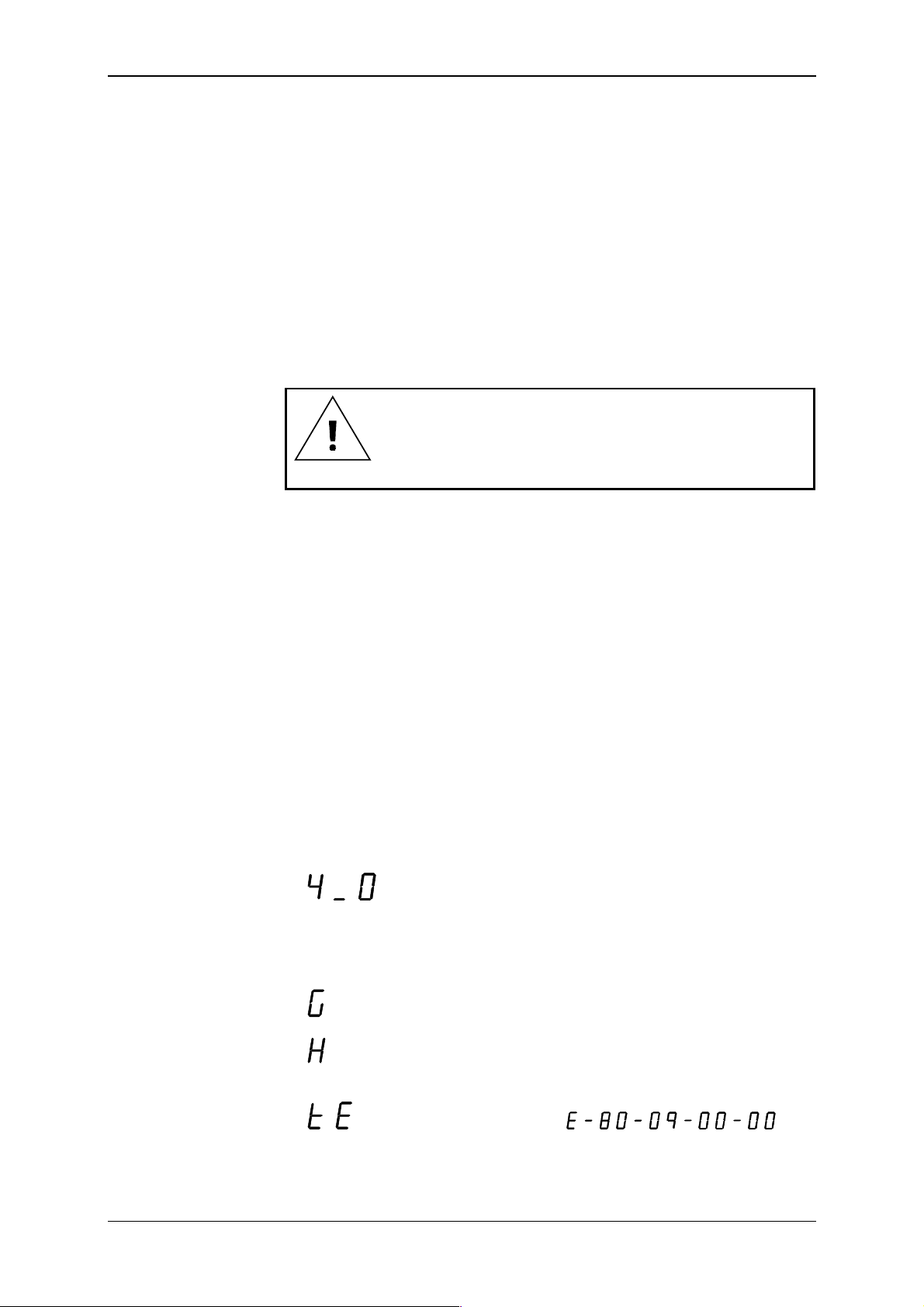
Tecomat TC600
10. Attendance
10.1 Instructions for Safe Attendance
When t he power supply i s on, it i s not all owed to di sconnect and connec t
supplying term inal boards neither to connect and disconnect indi v idual conductors of t he termi nal boards.
When pr ogr amming controlling PLC algorithms, the possibility of an error
in the user program cannot be exc luded the result of which m ay be unexpected behav i our of t he contr oll ed obj ect the consequence of which m ay be
originat ion of break down situation and in t he extreme case also endangering
of persons. In attendance t o the P LC, especi all y i n t he testi ng stage and debugging of new user programs with the controlled object, it is unconditional ly
necessary to be concerned with great er c ar efulness.
The producer is not r esponsible for damages caused by
improper attendance or inc or r ec t algorithm of the user
program.
10.2 Putting into Operation
When put ting the PLC i nto operati on for the f irst t ime, i t is necessary to
meet the following procedure:
check correct ness of the c onnecti on and volt age value of t he PLC power
supply
check interconnection of the PLC protective connectors with the main
protecti ve connector of t he distribution board or case
check correct ness of the c onnecti on and volt age value of t he power sup-
ply of input and output c ircuit s
turn on the P LC power supply
10.3 PLC Initialization
After the power supply is turned on, the PLC tr ansfers to t he starti ng sequence. The starting sequence is used for testi ng of the pr ogram and technical equipment of the PLC and setting of the PLC to the defined initial
state.
In the course of the starting sequence, version of the system program
equipment is gradually shown on the displ ay , for exampl e:
PLC binary outputs are blocked in the still state in the course of the testing (the BLK si gnal is li ghted in the f ield of binary out puts) and analog out puts are set to zero.
The starting sequence may be terminated by transferring to the RUN
mode and display ing
,
by transferr ing to the HALT mode and displaying
,
by transferr ing to the SET mode (see Article 4.5) or transferring to the HALT
mode with di spl ay ing of t he er r or message
, or full error code, for example .
TXV 138 08.02 58
Page 59

Mode RUN
Mode HALT
Mode SET
Technical equipment of TC600 PLC
10.4 Operational Modes
The PLC may oper ate in three basic modes.
The RUN mode is a common operati onal mode i n which val ues of input
signals are scanned, operations given by the user program algorithm are
perform ed, and PLC outputs are set. The PLC transfers in t he RUN mode
automatically after proper termination of the starting sequence. In the
course of the mode, let ter G is shown on the display.
The HALT mode is an operational m ode i n which t he user program i s not
run and the PLC is in a defined state. The PLC transf ers to the HALT mode
automati call y when a critical er ror is ev aluat ed during t he starting sequence
or in the course of control and after t er mination of t he S E T mode.
If t he PLC transfers to the HALT m ode from t he starting sequence, binary outputs remain blocked in the still state, analog outputs remai n set to
zero and code of the error message is shown on the display.
If the PLC transfers in the HALT mode after termination of the SET
mode, bi nar y outputs remai n blocked in t he still state, analog outputs remain
set to zero and let ter H or an error message are is shown on the display.
Mode HALT evoked by term inati on of the SET mode can be ter minated ei ther by the superior system or by turning of f and on of the PLC power supply.
If t he PLC transfers to the HALT m ode in the course of control, bi nary
outputs are set in the still state and blocked, analog out puts are frozen in the
state in which they were in the moment of transferr ing to the HALT mode,
and an error message is shown on the display.
For transf er to the HALT mode controlled by the user see item 10.4.1.
The SET m ode serves f or setting of comm unicati on paramet ers, setting
of the tim e circui t, and control of act iv ati on of the source user program . Entrance in the m ode is controll ed by the attendanc e persons at turning on of
the PLC power supply. In the course of the mode, binary outputs are
blocked in the still state, and analog outputs are set to zero. Af ter termi nation of t he SET mode, the P LC transfers automat ically t o the HALT mode.
Detailed description of setting of the PLC parameters is given i n A r ticle 4.5.
Transfer from the
HALT to RUN mode
Transfer from the
RUN to HALT mode
10.4.1 Change of Operational Modes
Transfer between RUN and HALT modes controlled by the attendance
persons is possible only using the superior system equipped with an integrated dev el opm ent envir onm ent f or program m i ng of the Tec om at PLC's or
with a moni tori ng and cont rol li ng progr am . T ransf er between t he m odes has
practical foundation only in the phase of debugging of the user program . In
general, i t can be said that transf er between the modes if a device i s connected, especial ly modif ication of t he PLC activ ity at transfer bet ween the
modes, requires perfect knowledge of the control led obj ect as well as of the
PLC, and careful considerat ion of possibl e c onsequences.
When changing the PLC operational modes, some activities are perform ed on the standard basis, and some can be perf orm ed opt ional l y. In t he
case that the change of the PLC m ode is done using the PLC dev elopm ent
envi ronment, optional activi ties at changing of the mode are a part of t he
development envir onment m enus.
10.4.2 Activities Perfo rmed at Changing of the PLC Mode on the
Standard Basis
In transfer from the HALT to RUN mode, the following is performed:
test of the user program integrity
check of software configuration given in the user program (see item
10.5.2)
running of the user program solv ing
In transfer from the RUN to HALT mode, the following is performed:
stopping of the user program sol vi ng
setting of outputs i n a defined stat e
59 TXV 138 08.02
Page 60

Tecomat TC600
Options at t r ans fer
from HALT t o RUN
Options at t r ans fer
from RUN to HALT
If a cr itical er ror occurs in the course of activ ities perf ormed at transfer
between the modes, the PLC sets the HALT mode, shows on the display t he
error code, and expects removal of the error c ause.
Do not in any case repl ac e stopping of control using the
HALT mode by function of the button CENTRAL STOP.
10.4.3 Optionally Performed Activities at Change of the PLC M ode
At transfer f rom the HALT m ode to RUN, it is possible to opti onally perform the following:
resetti ng of the PLC err or
warm or cold reboot
blocking of out puts at solv ing of t he user progr am
At transfer f rom the RUN mode t o HALT, it is possible to opti onally perform the following:
resetti ng of the PLC err or
setting of the PLC out puts to zero
At resetti ng of the PLC err or , the whole PLC error stack is reset.
The request for blocking of the P LC outputs causes the program to be
solved with disconnect ed binary out puts. Bl ock ing of the output s is indi cat ed
by the BLK LED di ode in the f ield of binary outputs.
At setting of the outputs to zero, all im ages of t he PLC bi nar y outputs are
set to zero.
Activities per formed
during restart
Running of the program without r es tart
Restarts af ter turning
on
User processes at
restart
Change of the
program during PLC
operation
10.4.4 Restarts of the User P rogram
Restart means such a PLC acti vi ty, the pur pose of which is prepare the
PLC for solvi ng of the user progr am . Under nor m al c ir cum stances, restar t i s
perform ed after turni ng on of the power supply, and at ever y change of t he
user program.
The systems distinguish two types of restart, warm and c old. Warm restart all ows for ret aining of t he values in t he remanent part of t he scratchpad. Cold restart is always performed with full m emory initialization.
During restart, the following is performed:
test of integrity of the user program
resetti ng of the whole PLC scrat c hpad
resetti ng of the remanent zone (onl y at cold restart )
setting of the remanent zone (onl y warm restart)
ini tialization of system registers S
ini tialization and chec k ing of PLC inputs and outputs
When t he user program is run without a restart, onl y test of integri ty of
the user program is performed and checking of the PLC i nputs and outputs.
After being turned on, the PLC perf orms the restart type chosen by the
user. If damage of data found in the remanent zone of the scratchpad
memor y is evaluated, PLC perform s cold restart without regard t o the chosen restart type.
Depending on the perf orm ed restart, t he planni ng uni t of user processes
P operates as well. If you hav e perf orm ed warm restart at transf er f rom t he
HALT to RUN mode, aft er transferring to t he RUN mode the user process
P62 is solv ed fir st (if pr ogramm ed). At col d restart, af ter transferri ng to t he
RUN mode the user process P63 is solved f ir st (i f program m ed). If onl y one
of the processes P62, P63 is programmed, then t his process is perf orm ed i n
the case of warm as well as cold r estart. If t he process P62 neither P63 is
programmed, then process P0 is solved first after transfer to the RUN
mode.
Programming of the xPRO environment allows for change of the program duri ng PLC operat ion. Here i t i s necessary to keep i n m ind t hat duri ng
TXV 138 08.02 60
Page 61

PLC programming
xPRO development
environment
Technical equipment of TC600 PLC
recording of the new program, solving of the program is stopped without
blocking of outputs. This state may last ev en several seconds!
10.5 Programming and Debugging of the PLC Program
Programming of control algorithms and testing of correctness of the
written program s for T ECOMAT PLC's is perf orm ed using com puters of the
PC standard. For connec ti on with t he PLC, the serial channel of these c om puters is used.
Diskette with ex amples and the x PRO devel opment env ironm ent in t he
versi on xPRO Li te and xPROm is deliver ed with ever y P LC.
Examples of PLC programs contain instructions for attendance of various PLC units.
The xPRO integrated dev elopment env ironment is av ailable in the following versions:
xPRO - f ull version with t he hw key for professional work
xPRO Lite - freely di str ibutable version wit hout the hw key
xPROm - f r eely distributable version i ntended for chec k ing of t he
technology operation with exclusion of the possibility of interventions in t he P LC user progr am
The xPRO devel opment environment has the f ollowing propert ies:
integr ated environment Turbo Vision including the editor
possibility to work with several files at the same time, every one of them
having its own window
compiler i nto the machine code of pr oc essors of all series
symbol ic names of labels and operands
autom atic assignment of variables
generati on of the sym bols table and cross ref er enc es
creation of macro-instruc tions
backward compilation of the pr ogr am
buil t-in simulator of the TECOMAT PLC
full use of the PLC debugging m eans
autom atic generation of configuration according to the connect ed P LC
contact pl an (rel ay l i ne schemes) wit h parti al l ight i ng of connect i on pat hs
in the debugging mode
integrated sensitive help system containing the whole programmer's
handbook
c ontrol using the mouse or the keyboard with the possibility to use both
the program m enus (pull down menus) as well as the di rect selecti on re-
alized by pr essing of a key combinati on ( hot keys)
61 TXV 138 08.02
Page 62

Tecomat TC600
Configuration of
constants f or s etting
of services prov ided
during the PLC
operation
10.5.1 Configuration Constants in the User Program
Configuration constants are automatically generated during compi lation
of the user program, and they f orm its non-separable part. T hey carry inf ormati on on the required PLC mode and i ts use. Constants can be set using
menus of the xPRO i ntegrat ed com pi l er environm ent bef ore t he com pi l ati on
itself.
Configur ation constants contain the f ollowing services:
type of restart after turning on of t he P LC power supply
This determ ines whether after turni ng on of the power supply, warm or
cold restart will be performed (see item 10.4.4). Cold restart is the default
setting.
t ime of issuing the f irst warning of threat of ex ceeding of the m axim um
allowed cycle time
If the cycle of processing the user program lasts longer t han the t im e de-
fined by this constant, PLC system services set the bit S 2.7 as a flag that
in processing of the program, the set ti me has been exc eeded in thi s cy-
cle, and at t he same t i m e the sof t er ror code i s set in t he system r egister
S34 and S48 to S51. Default set val ue is 150 ms.
time of guardi ng the maximum allowed cycle time
If the cycle of processing of the user program lasts longer than the
maxi mum allowed cycle time, PLC announces crit ical error of ex ceeding
the cycle time, blocks the outputs and interrupts cycling running of the
user program. This constant defines the longest possible time during
which the controlled object may remain without an action intervention.
The defaul t set value i s 250 ms, the recommended m aximum value is
500 ms.
determining of t he ext ent of backup of the user program in EEPROM
Defines whether the whole user program i s backed includi ng tables T or
whether the user program is backed without the tables T and tables T
remain in the ori ginal v ersion i n backed RAM (suit able i n cases of modi -
fication of the tables by the user program). Backing of the whole user
program i s the default setting.
number of backed registers R (remanent z one)
Setting of the number of backed registers R values of which will be
saved in the case of the PLC power supply failure, ensured by the
checking character , and retrieved in the c ase of warm restart of t he PLC.
Registers are saved star ting f rom register R0, state of the registers af ter
the last fully terminated cycle of solving of the user program is backed.
Default set value is 0.
TXV 138 08.02 62
Page 63

Softwar e and har dware configuration
Technical equipment of TC600 PLC
10.5.2 Software Co nfiguration
Software (sw) conf igurati on of inputs and output s describes the PLC set,
and forms a non-separable part of the user program. Before running of
solvi ng of the user progr am, thi s description i s compared wit h reali ty f ound
out during the P LC star ting sequence (the so c alled har dware c onfiguration).
It allows for perfec t checking of readiness of the whole PLC f or the control
before running the program . At the same ti me, the user gains the possibility
to practical ly arbi trari ly assign placem ent of im ages of i nputs and outputs in
zones X, Y, R, and gradually acti vate inputs and output s at debugging of the
program without the necessity of physical disconnection or connecti on of the
terminal boards.
In the xPRO program, sw configuration is entered using the directive
#unit
. Structure of the di rect ive i s identi cal wit h other T ecom at PLC di rec-
tiv es. Som e paramet ers intended f or descri ption of more ext ensiv e system ,
have t he c har ac ter of a constant in the TC600 series.
General structure of t he directi ve i s as f ollows:
#unit MODUL, ADR, TYP, POC_IN, POC_OUT, Z_IN, Z_OUT, AKT,
INITAB
MODUL - always 0 for the TC600 series
ADR - always 0 for BM binar y and analog inputs and output s
- always 1 for bi nar y inputs and outputs and analog inputs of
the
first EM/2
- always 2 for bi nar y inputs and outputs and analog inputs of
the second EM/2
- always 2 for EM binary input s and outputs and analog inputs
- always 2 for the CH2 serial channel
- always 3 for the CH3 serial channel
TYP - t y pe of input s or out puts
$10 - serial channel CH2 or CH3
Parameters MODUL, ADR, TYP of serial channel 2 (3) can
be entered together in the symbolic way CH2 (CH3)
$80 - E M /2 binary i nputs or outputs (TC631, T C632)
$90 - E M /2 binary i nputs or outputs (TC633)
$A0 - E M , BM binary inputs or outputs
Parameter TYP of binary inputs or outputs can be entered for
the BM and EM sym bolical ly as Digit_600, for EM/2
Digit_63x (TC631, TC632) and Digit_633 (TC633)
$D0 - analog inputs or outputs
Parameter TYP of analog inputs or outputs can be entered
form BM, EM and EM /2 symbolically as Analog_600_
POC_IN - number of input bytes
POC_OUT - number of output bytes
Z_IN - placement of the first input by te in the scratc hpad
Z_OUT - placem ent of the first output byte i n the scratchpad
The paramet er is entered absolutel y , for exampl e Y0, R128
..., or symbolically
AKT - activation of serv icing of inputs or outputs
Parameter is entered symbol icall y
X_On - activation of servicing of i nputs
X_Off - servicing of input s i s not ac tivated
Y_On - activation of servicing of outputs
Y_Off - servicing of outputs i s not ac tivated
On - simultaneous activation of servic ing of inputs as
well as outputs
Off - serv icing of inputs neither outputs is activ ated
63 TXV 138 08.02
Page 64

Tecomat TC600
INITAB - addr ess of the table cont aining the initi alization data
Parameter is entered symbol icall y , for exampl e IniCH2, or
absolutely, for ex ample T0 (nam es used in t he following examples of declarations are not m andatory).
Entering of the parameter f or CH2, CH3, analog i nputs and
some special functi ons (see further) i s mandatory. T he parameter is not entered for binary inputs and outputs.
Declaration of special
functions
Automatic generation
of the sw
configuration
Solving of the user
program with
disconnected inputs
and outputs
Another possibility of the sw configuration is declaration of the PLC special f unctions. Speci al functi on use standard-fit ted PLC inputs and outputs,
however thei r serv ici ng requir es more com pli cated shell algori thms or com plement ation of the basic technical equipment of the input and out put unit.
These servici ng algori thm s are real i zed by t he system , t hus serv ic ing by the
user program remains simple.
The xPRO program c ontains the f unct ion f or autom atic generation of sw
configuration according to the connected PLC type and its further editi ng.
This enables the user to hav e the sw configurat ion creat ed exact ly acc ording the real tec hnical equi pment or creat e a basis for the user's own declaration of inputs, out puts, and funct ions of the PLC set.
If no sw configuration is entered in the user program, the program will be
solved only above the PLC scratchpad memory and the PLC inputs and
outputs will not be serviced. Binary outputs will remain blocked in this case
and analog outputs will remain set to zero.
TXV 138 08.02 64
Page 65

Declaration of BM
binary inputs
Technical equipment of TC600 PLC
10.5.3 Servicing of Binary Inputs
BM binary input s are assigned to the scratchpad m emory together with
binary outputs by the directive #unit with general structure according to
10.5.2.
Example of declarat ion
for TC601 BM
Example of declarat ion
for TC602 BM
Example of declarat ion
for TC603 BM
Example of declarat ion
for BM of T C604,
TC605, TC606
Example of
declaration for T C607
Declaration of EM
binary inputs
Example of declarat ion
for TC621 EM
Example of declarat ion
for TC622 EM
Example of declarat ion
for TC623 EM
Example of declarat ion
for EM of T C624,
TC625, TC626
#unit 0, 0, Digit_600, 2, 1, X0, Y0, On
; binary inputs and transistor outputs
#unit 0, 0, Digit_600, 3, 2, X0, Y0, On
; binary inputs and transistor outputs
#unit 0, 0, Digit_600, 2, 1, X0, Y0, On
; binary inputs and transistor and relay outputs
#unit 0, 0, Digit_600, 2, 2, X0, Y0, On
; binary inputs and relay outputs
#unit 0, 0, Digit_600, 3, 3, X0, Y0, On
; binary inputs and transistor outputs
EM binary input s are assigned to the scratchpad m emory together with
binary outputs by the directive #unit with general structure according to
10.5.2.
#unit 0, 2, Digit_600, 2, 1, Xn, Yn, On
; binary inputs and transistor outputs
#unit 0, 2, Digit_600, 3, 2, Xn, Yn, On
; binary inputs and transistor outputs
#unit 0, 2, Digit_600, 2, 1, Xn, Yn, On
; binary inputs and transistor and relay outputs
#unit 0, 2, Digit_600, 2, 2, Xn, Yn, On
; binary inputs and relay outputs
Placement of images of i nputs (parameter Xn) and outputs (parameter
Yn) depends on the type and fitti ng of the BM or possibly on the type of
EM/2 of the PLC set.
Declaration of EM/2
binary inputs
Example of declarat ion
for TC631 EM/ 2
Example of declarat ion
for TC632 EM/ 2
Example of declarat ion
for TC633 EM/ 2
EM/2 binary input s are assigned to the scrat chpad m em ory toget her with
binary outputs (TC631, TC632) or individually (TC633) by the directive
#unit with general structure according to 10.5.2.
#unit 0, ADR, Digit_63x, 1, 1, Xn, Yn, On
; binary inputs and transistor outputs
#unit 0, ADR, Digit_63x, 1, 1, Xn, Yn, On
; binary inputs and relay outputs
#unit 0, ADR, Digit_633, 2, 0, Xn, 0, On
; binary inputs
The module address (parameter ADR) depends on placement of the
module towards the BM. Address 1 is assigned to the f irst EM/2, address 2
is assigned to the second EM/2. Pl acement of im ages of inputs (param eter
Xn) and outputs (paramet er Yn) depends on the type and f itti ng of the BM,
or possibly on the ty pe of the fi rst EM/2 of t he PLC set. In automatic generation of the sw configurati on, images of inputs and output s of BM, EM/2
and EM form a conti nuous series.
65 TXV 138 08.02
Page 66

Tecomat TC600
Servicing of binary
inputs
Structure of binary
inputs zone
Declaration of binary
outputs
Servicing of binary
outputs
Structure of binary
outputs zone
Binary inputs of BM, EM and EM/2 occupy in the inputs image in the
scratchpad 1 to 3 bytes dependi ng on the m odul e ty pe ( param eter of t he di rective #unit POC_IN = 1, 2 or 3). State of signal s at the PLC i nputs
is overwritten in the cycle loop in the scratchpad zone with the initial address defined by the par ameter Z_IN of direct iv e #unit.
Zone of binary inputs i n the scratchpad has the f ollowing struct ur e:
bit.7.6.5.4.3.2.1.0
DI7 DI6 DI5 DI4 DI 3 DI 2 DI 1 DI 0
DI15 DI14 DI13 DI12 DI11 DI10 DI9 DI8
DI19 DI18 DI17 DI16
Z_IN
Z_IN+1
Z_IN+2
Besides the way given above, binary inputs are accessible by direct
reading of instructions LD with the operand U and the physical input address. For structure of the physical address see item 10.5.12.
10.5.4 Servicing of Binary Out puts
Binary output s are assigned to the scratchpad mem ory toget her with bi nary inputs by the directive #unit with general structure according to
10.5.2. For examples of declar ation see 10.5.3.
Binary output s of BM, EM and EM/2 occupy i n the outputs im age in the
scratchpad 1, 2 or 3 byt es depending on the m odule type ( paramet er of the
directiv e #unit POC_OUT = 1, 2 or 3 ). Setti ng of the output s is done
in the cycle l oop according to the stat e of the output s image with the ini tial
address defined by the par ameter Z_OUT of directiv e #unit.
Zone of binary outputs in the scratchpad has the f ollowing struct ur e:
bit.7.6.5.4.3.2.1.0
DO7 DO6 DO5 DO4 DO3 DO2 DO1 DO0
DO15 DO14 DO13 DO12 DO11 DO10 DO9 DO8
DO19 DO18 DO17 DO16
Z_OUT
Z_OUT+1
Z_OUT+2
Checking of overload
of binary outputs
Declaration of analog
inputs
Besides the way of outputs control gi ven abov e, binary outputs are accessible by direct writing of instructions WR with the operand U and the
physical output address. For structure of the physical address see item
10.5.12.
PLC's of the T C600 series allows for program -checki ng of outputs overload. This state is signall ed at bit S35. 1:
S35.1 = 0 - output s are in correct stat e
S35.1 = 1 - ov er load of out puts
When S35.1 = 1, the soft PLC error is also evoked with the code
40 00 50 A0, signalled in S34 and S48 to S 51.
10.5.5 Servicing of Analog Inputs
Analog inputs of BM, EM and EM/2 are assigned to the scratchpad
memor y by the directiv e #unit with general struc ture according to 10. 5.2.
Parameter
INITAB
of the directiv e is mandatory. In the case that t he BM is
fitted with the piggyback OT-13 or OT-14, analog inputs are declared together with the BM analog outputs.
TXV 138 08.02 66
Page 67
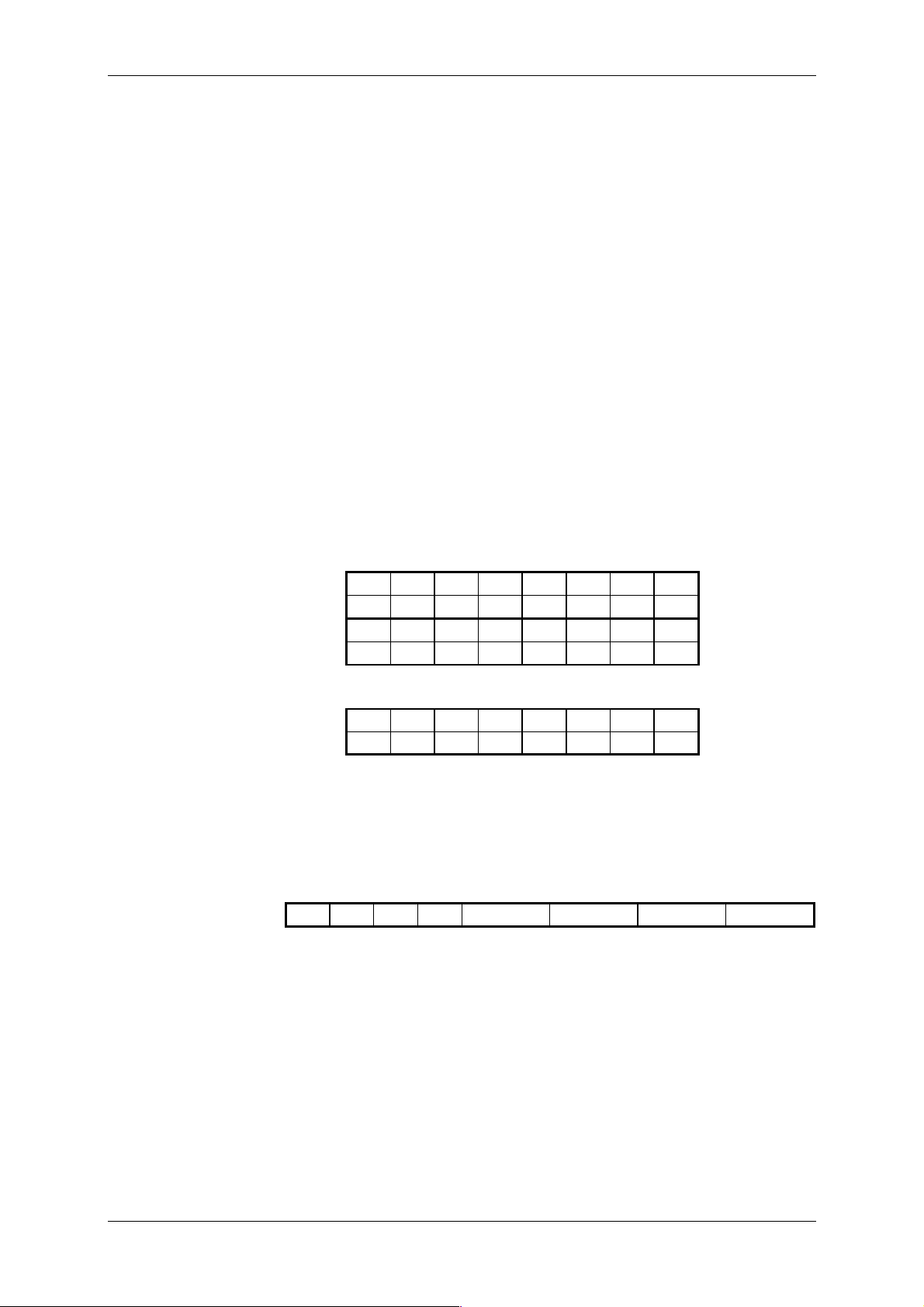
Technical equipment of TC600 PLC
Example of
declaration for BM of
TC605 and TC606
Example of declarat ion
for EM of T C625 and
TC626
Example of declarat ion
forTC634 EM/ 2
Servicing of analog
inputs of
TC605, TC606 and
TC625, TC626
Structure of analog
inputs zone of
TC605, TC606
and TC625, TC626
#unit 0, 0, Analog_600_, 8, 0, X2, 0, On, IniAI
#unit 0, 2, Analog_600_, 8, 0, X2, 0, On, IniAI
; analog inputs
; analog inputs
Placem ent of im age of i nputs (param eter Xn) or possibly of output s (parameter Yn) depends on the type and fi tting of the BM , or possibly on the
type of E M /2 of the P LC set.
#unit 0, ADR, Analog_600_, 16, 0, Xn, X_On, Ini634
; analog inputs
Module address (paramet er ADR) depends on placement of the m odule
towards the BM. Address 1 is assigned to the f irst EM/2, address 2 is assigned to the second EM/2. Placement of the image of inputs (parameter
Xn) depends on the type and fitti ng of the BM, or possibly of the t ype of the
fir st EM/2 of the PLC set. In automati c generation of sw configurat ion, im ages of inputs and outputs of BM, E M /2 and EM for m a conti nuous series.
Analog inputs of TC605 and TC606 BM, and of TC625 and TC626 EM,
occupy 8 bytes in the inputs i mage in the scratchpad ( parameter of the directive
#unit POC_IN = 8
). Binary representation of the inputs state is
overwrit ten in the cycle loop into the scratchpad zone wit h the i nitial address
defined by the parameter
Z_IN
of dir ec tive
#unit
.
Zone of analog inputs in t he scratchpad has the following structur e:
.7 .6 .5 .4 .3 .2 .1 .0
AI0
.11 .10 .9 .8
.7 .6 .5 .4 .3 .2 .1 .0
AI1
.11 .10 .9 .8
Z_IN
Z_IN+1
Z_IN+2
Z_IN+3
.
.
.7 .6 .5 .4 .3 .2 .1 .0
AI3
.11 .10 .9 .8
Z_IN+6
Z_IN+7
Setting of analog
inputs range of
TC605, TC606
and TC625, TC626
Example of analog
inputs initialization
table o TC605, TC606
and TC625, TC626
Besides the way of contr ol giv en above, anal og input s are accessible by
direct reading of instructions LD with t he operand U and physical input address. For structure of the physical address see item 10.5.12.
Range of analog inputs is set i n the ini ti aliz ation t able with t he name defined by the parameter
INITAB
of directive
. The table contains 1
#unit
byte with the foll owing meaning:
.7 .6 .5 .4 .3 .2 .1 .0
range AI3 range AI2 range AI1 range AI0
value of the appr opr iate bit 0 = v oltage range 0 to + 10 V
value of the appr opr iate bit 1 = v oltage range 0 to + 2 V
For the current range of 0 t o 20 mA, the appr opr iate bit is set to
value 1.
#table byte IniAI = %00000011
;range of inputs AI0, AI1 0 to 2 V
;range of inputs AI2, AI3 0 to 10 V
67 TXV 138 08.02
Page 68
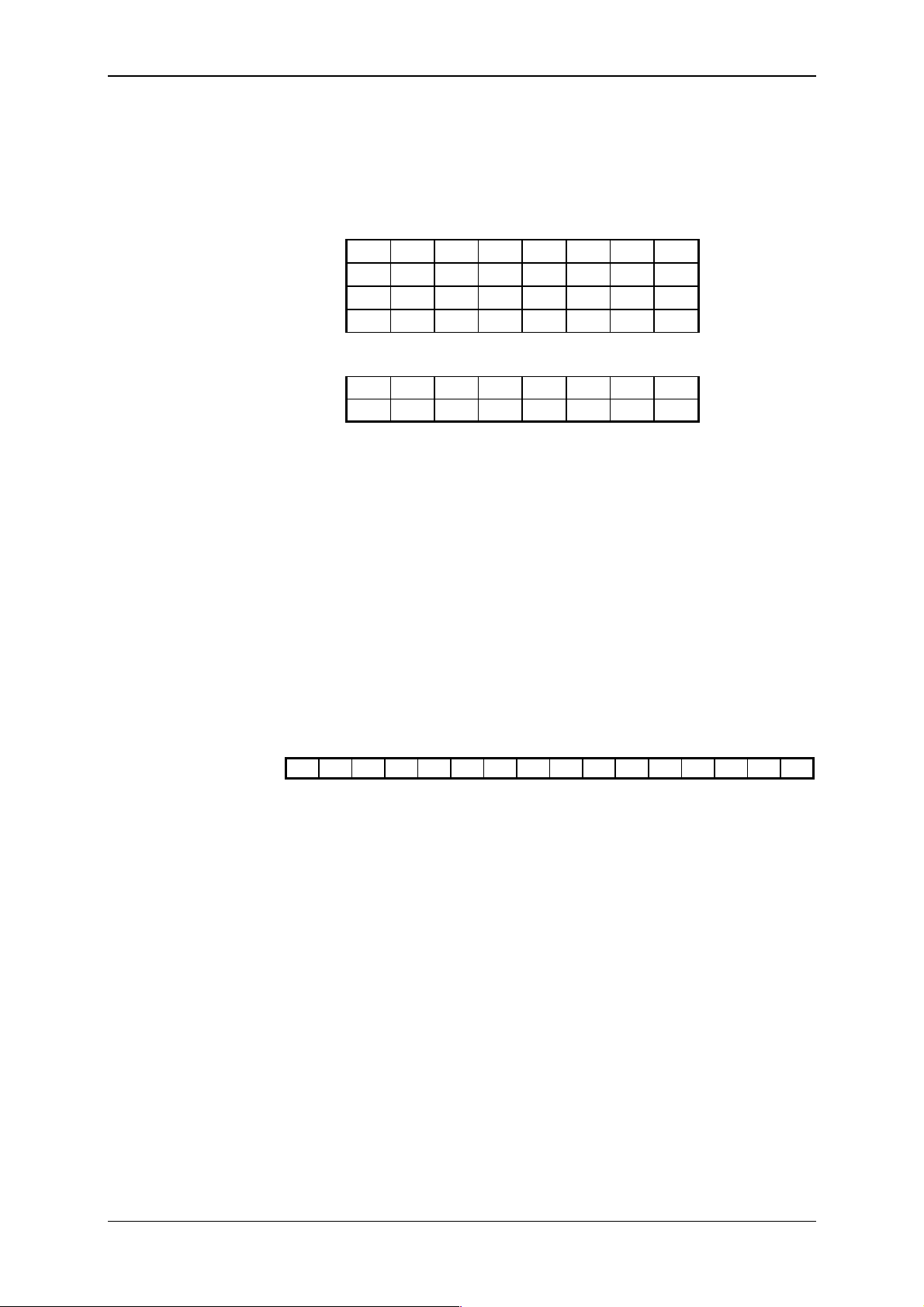
Tecomat TC600
Servicing of TC634
analog inputs
Structure of TC634
analog inputs zone
Setting of t y pe of
inputs, measurem ent
ranges and formats of
input data of TC634
TC634 analog inputs occupy 16 bytes in the i nputs im age in the scrat chpad (parameter of the di rectiv e #unit POC_IN = 16). Bi nary representation of the inputs state is overwrit ten in the cycle loop i nto the scratchpad
zone with the initial address defined by the parameter Z_IN of directive
#unit.
Zone of analog inputs in t he scratchpad has the following structur e:
.7 .6 .5 .4 .3 .2 .1 .0
AI0
.15 .14 .13 .12 .11 .10 .9 .8
.7 .6 .5 .4 .3 .2 .1 .0
AI1
.15 .14 .13 .12 .11 .10 .9 .8
Z_IN
Z_IN+1
Z_IN+2
Z_IN+3
.
.
.7 .6 .5 .4 .3 .2 .1 .0
AI7
.15 .14 .13 .12 .11 .10 .9 .8
Z_IN+14
Z_IN+15
TC634 analog input s are not accessible by direct readi ng of i nstructi on
LD with the operand U and the physi c al input address.
Type of inputs, the measurement range and format of input data of
TC634 analog input s is set in the init ializati on table with the name def ined
by the paramet er INITAB of di rect i v e #unit. The tabl e contains 8 i tems of
the type word with the foll owing meaning:
Structure of the
TC634 initialization
table
Structure of the
TC634 control w or d
CONT
#table word Ini634 = CONT 0, ;setting of input AI0
CONT 1, ;setting of input AI1
CONT 2, ;setting of input AI2
CONT 3, ;setting of input AI3
CONT 4, ;setting of input AI4
CONT 5, ;setting of input AI5
CONT 6, ;setting of input AI6
CONT 7 ;setting of input AI7
The CONT cont r ol word has the following structure:
.15 .14 .13 .12 .11 .10 .9 .8 .7 .6 .5 .4 .3 .2 .1 .0
AK - - - - - V1 V0 SN3 SN2 SN1 SN0 TP3 TP2 TP1 TP0
TP0-TP3 select ion of scanner t y pe or r ange
SN0-SN3 selection of input type
V0-V1 format of input data
AK channel activati on
0 = channel off
1 = channel on
TXV 138 08.02 68
Page 69
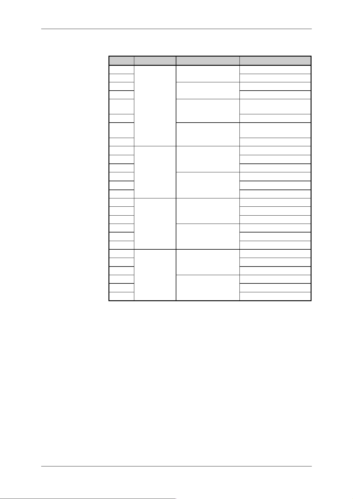
Technical equipment of TC600 PLC
Valid values of the
TC634 control w or d
The fol lowing table gi ves al lowed val ues of the CONT control word with
the corresponding selections:
CONT Input type Scanner/range type Format of input data
$8020 Resistanc e Pt 100, W 100 = 1.385 0 to 65535
$8120 temperature -200 to + 850 °C -2000 to + 8500 [0.1°C]
$8022 scanners P t100, W100 = 1.391 0 to 65535
$8122 -200 to +850 °C -2000 to +8500 [0. 1°C]
$8027 Ni1000, W100 =
0 to 65535
1.617
$8127 -60 to +200 °C -600 to +2000 [0. 1°C]
$8029 Ni1000, W100 =
0 to 65535
1.500
$8129 -60 to +200 °C -600 to +2000 [0. 1°C]
$8030 Resistanc e
$8130 scanners
0 to 630
0 to 65535
0 to 6300 [0.1
$8230 0 to 10000
$8032
$8132
0 to 2520
0 to 65535
0 to 25200 [0.1
$8232 0 to 10000
$8040 Current 0 to 20 mA 0 to 65535
$8140
0 to 20000 [A]
$8240 0 to 10000
$8042 4 to 20 mA 0 to 65535
$8142
40000 to 20000 [A]
$8242 0 to 10000
$8080 Voltage 0 to 10 V 0 to 65535
$8180
0 to 10000 [1 mV
$8280 0 to 10000
$8082 0 to 2 V 0 to 65535
$8182
0 to 20000 [0.1 mV
$8282 0 to 10000
1)
Example of TC634
declaration
1)
For details see item 5. 1.5
The following example gi ves declar ation of the TC634 module connected
according to Figs. 9.21 a 9.22.
#table word Ini634 = $8140, ;AI0 - 0 to 20mA/µA
#unit 0, 1, Analog_600_, 16, 0, R0, X_On, Ini634
$8142, ;AI1 - 4 to 20mA/µA
$8180, ;AI2 - 0 to 10V/mV
$8182, ;AI3 - 0 to 2V/0,1mV
$8120, ;AI4 - Pt100, W100 = 1.385/0,1°C
$8122, ;AI5 - Pt100, W100 = 1.391/0,1°C
$8127, ;AI6 - Ni1000, W100 = 1.617/0,1°C
$8129 ;AI7 - Ni1000, W100 = 1.500/0,1°C
; TC634 in position 1. EM
; data from R0
69 TXV 138 08.02
Page 70

Tecomat TC600
Declaration of optional
analog outputs
Declaration of the
piggyback OT-13 and
OT-14 in BM of
TC601 to TC604
Declaration of the
piggyback OT-13 and
OT-14 in BM of
TC605, TC606
10.5.6 Servicing of Analog Outputs
In the case of fit ti ng the opt i onal pi ggybac k OT -13 or O T- 14, t he sw configur ation of BM standar d-fitt ed inputs and outputs is com plemented in the
way which depends on the BM type.
In BM of TC601 to TC604, the sw confi gurati on is com plem ented by the
new directiv e
#unit
pi ggyback OT -13 or OT -14. Ex ampl e of t he di -
for the
rective:
#unit 0, 0, Analog_600_, 0, 4, 0, Yn, On
#unit 0, 0, Analog_600_, 0, 8, 0, Yn, On
; analog outputs of OT-13
; analog outputs of OT-14
Placem ent of image of outputs (paramet er Yn) depends on the BM type
(is link ed to image of binary outputs).
In BM of TC605 and TC606, the directi ve
#unit of anal og inputs and
outputs is complem ented by paramet ers for t he piggyback OT-13 or O T-14.
Exam ples of the extended direc tive:
#unit 0, 0, Analog_600_, 8, 4, X2, Yn, On, IniAI
#unit 0, 0, Analog_600_, 8, 8, X2, Yn, On, IniAI
; analog inputs of BM
; and analog outputs of OT-13
; analog inputs of BM
; and analog outputs of OT-14
Servicing of analog
outputs
Structure of analog
outputs zone
Declaration of serial
channels CH1, CH2,
CH3
Placem ent of image of outputs (paramet er Yn) depends on the BM type
(is link ed to the image of bi nar y outputs).
BM analog outputs occupy 4 or 8 bytes in the im age of outputs in the
scratchpad, depending on the type of the f itt ed piggyback (paramet er of the
directiv e
#unit POC_OUT = 4 or 8
). Setti ng of the outputs accor ding to
the binary repr esentation of lev els written in images of outputs is done in the
cycle loop. Initi al address of the zone in the scratchpad is defi ned by the parameter
Z_OUT
of dir ec tive
#unit
Zone of images of analog outputs in the scratchpad has the following
structure:
.7 .6 .5 .4 .3 .2 .1 .0
AO0
.7 .6 .5 .4 .3 .2 .1 .0
AO1
Z_0UT
Z_OUT+1
.
.
.7 .6 .5 .4 .3 .2 .1 .0
AO7
Z_OUT+7
Besides the way of outputs control gi ven abov e, analog outputs are accessible by direct writing of instructions WR with the operand U and the
physical output address. For structure of the physical address see item
10.5.12.
10.5.7 Servicing of Serial Channels
Declaration of CH1 i s not per form ed.
CH2 is assigned to the scratchpad memor y by t he direct iv e
#unit
wit h
general structur e ac c or ding to 10.5.2.
CH3 is declared i n the case that the opt i onal pi ggybac k MR-14 or M R-15
is fi tted, and in the same way as CH2.
Automatically generated sw configuration contains the directive
#unit
for CH2 and CH3 onl y after previ ous writ ing of t he directi ve by t he user.
Example of CH2 and
#unit 0, 2, _CHx, 255, 255, R0, R255, On, IniCH2
CH3 declaration for
BM of TC601 to
TC606
#unit 0, 3, _CHx, 255, 255, R510, R764, On, IniCH3
TXV 138 08.02 70
; serial channel CH2
; serial channel CH3
Page 71

Declaration of
interrupt inputs
Technical equipment of TC600 PLC
Serv icing of CH1, CH2, CH3 depends on the set m ode. CH1 has f ix edset mode PC, channels CH2 and CH3 have selectabl e modes (see Article
4.4 and 4.5). Detailed descript ion of t he modes incl uding t he servi cing t able
is giv en in the handbook
Logic Controllers, TXV 001 06.02
Serial Communication of Tecomat Programmable
.
10.5.8 Servicing of Interrupt Inputs
Declaration of i nterrupt inputs is done by the directive
structure according to item 10.5.2. Parameter
INITAB of the directive is
#unit with general
mandatory. The initi alization tabl e serves for def inition of edges of signals
which evok e the interrupt request (IRQ).
Structure of the
initialization table
Declaration example
#table byte IniTable = item 1, ;DI0 control
item 2, ;DI1 control
item 3, ;DI2 control
item 4 ;DI3 control
Items 1 to 4 may have the f ollowing values:
0 - wit hout IRQ
1 - I RQ allowed f r om the ascending signal edge
2 - I RQ allowed f r om the descending signal edge
3 - I RQ allowed f r om both signal edges
#def NO 0 ;without IRQ
#def UP 1 ;IRQ from the ascending signal edge
#def DOWN 2 ;IRQ from the descending signal edge
#def ALL 3 ;IRQ from both signal edges
;
#table byte IniIRQ = all, ;IRQ from both edges of input 0
no ;without IRQ from input 3
;
#unit 0, 0, IntIn_600_, Xn, Yn, On, IniIRQ
;
up, ;IRQ from ascending edge of input 1
down, ;IRQ from descending edge of input2
Parameter TYP, POC_IN, POC_OUT of the direct iv e #unit is input symbolically as
and control word (param et ers
IntIn_600_ or numeri cal l y $20, 1, 1. Pl acem ent of the state
Xn, Yn) depends on the BM type (on occ upa-
tion of the scratchpad by images of inputs and outputs).
Servicing of inter r upt
inputs
State wor d
Control word
Interrupt i nputs occupy 1 byte in the scratchpad i n the im age of i nputs
(state word) and 1 byte in the image of outputs (control word).
The STAT state word serves for distinguishing of the interrupt source.
Flags of the i nterrupt in the stat e word are set before r unning of the P42 i nterrupt process. The stat e word placed in t he scratc hpad at the address defined by par ameter
----STAT
Z_IN of dir ec tive #unit has the following structur e:
STAT.2STAT.1STAT
.3
.0
Z_IN
STAT.0 = 1 - interrupt from input DI0
STAT.1 = 1 - interrupt from input DI1
STAT.2 = 1 - interrupt from input DI2
STAT.3 = 1 - interrupt from input DI3
The CONT control word serves for allowing or prohibiting an interrupt
from i ndivi dual i nput s in the c ourse of t he program ex ecut ion. It i s acc epted
by the system after it is written t o the scratchpad. The control word placed in
the scratchpad at the address defined by parameter
#unit has the following structure:
Z_OUT of directive
71 TXV 138 08.02
Page 72

Tecomat TC600
PLC response time
Definition of tim es
----
CONT.3CONT.2CONT.1CONT
Z_OUT
.0
CONT.0 - interr upt allowed f r om input DI0
CONT.1 - interrupt allowed from input DI 1
CONT.2 - interr upt allowed f r om input DI2
CONT.3 - interr upt allowed f r om input DI3
0 = inter r upt prohibited
1 = inter r upt allowed
PLC response time is the sum of all ti mes with which processing of t he
interrupt is loaded since t he rise of the i nterrupt r equest at t he PLC input to
closing of the out put c losi ng elem ent . Response ti m e is af f ec ted not onl y by
the PLC properties, but also by the way of processing in the user program.
For better clari ty, the fol lowing descripti on contains also com parable parameters and the tim e diagram of pr ocessing of t he input signal of standard
binary inputs.
t
- minimum width of the input pulse (minimum lasting time of one
min
level of the input signal)
- min. 30 s for interrupt inputs
- for standard binary input s, at the mi nimum the lasti ng tim e of the
program cycle
, tIL- input del ay s
t
IH
Signal delay at passing through t he input f ilter.
- max. 5 s for interrupt inputs
- typically 4 ms for standard bi nar y inputs
- time of serving of the interrupt
t
VP
Tim e from the I RQ eval uation to running of the P42 process.
Most signif icant part of t
is form ed by the ti me necessary to the
VP
possible fi nishing of the cycle loop (m ax. 4 ms) and time necessary to finish user program instructions being processed at the
moment. In the case of some special instructions (for example
PID) or user instructions (f or exampl e TER_ID05), tim e for the i nstruction execution may reach up to 10 ms.
- max . 10 ms if servicing accor ding to Fi gs. 10.1 and 10.2
- not appli ed if servicing according to Fig. 10.3
- l asting time of t he P 42 pr oc ess
t
P42
- m ax. 5 m s i f servicing ac c or ding to Fi gs. 10.1 and 10.2
- not applied if serv icing accor ding to Fi g. 10.3
- lasting tim e of the cycle loop
t
OC
Time between two user program cycles following one after an-
other. Lasting ti me of the cycl e loop depends on the PLC set configur ation.
- max . 4 ms for the TC600 series
- - cycle lasting time
t
C
Lasting t im e of t he user program cycl e depends on t he t ask ex t ent
and structure of the user program.
- not appli ed if servicing according to Figs. 10.1 and 10.2
- max . 2550 ms if servicing accor ding to Fi g. 10.3
t
- time until t he cycle end
KC
Tim e until t he cycle end expresses situation which arriv es at syn-
chronization of the program response with the user program cycle
- not appli ed if servicing according to Fig. 10.1
- t
- max. t
- max. t
C
C
if servic ing according to Fig. 10.2
P42
if servic ing according to Fig. 10.3
TXV 138 08.02 72
Page 73
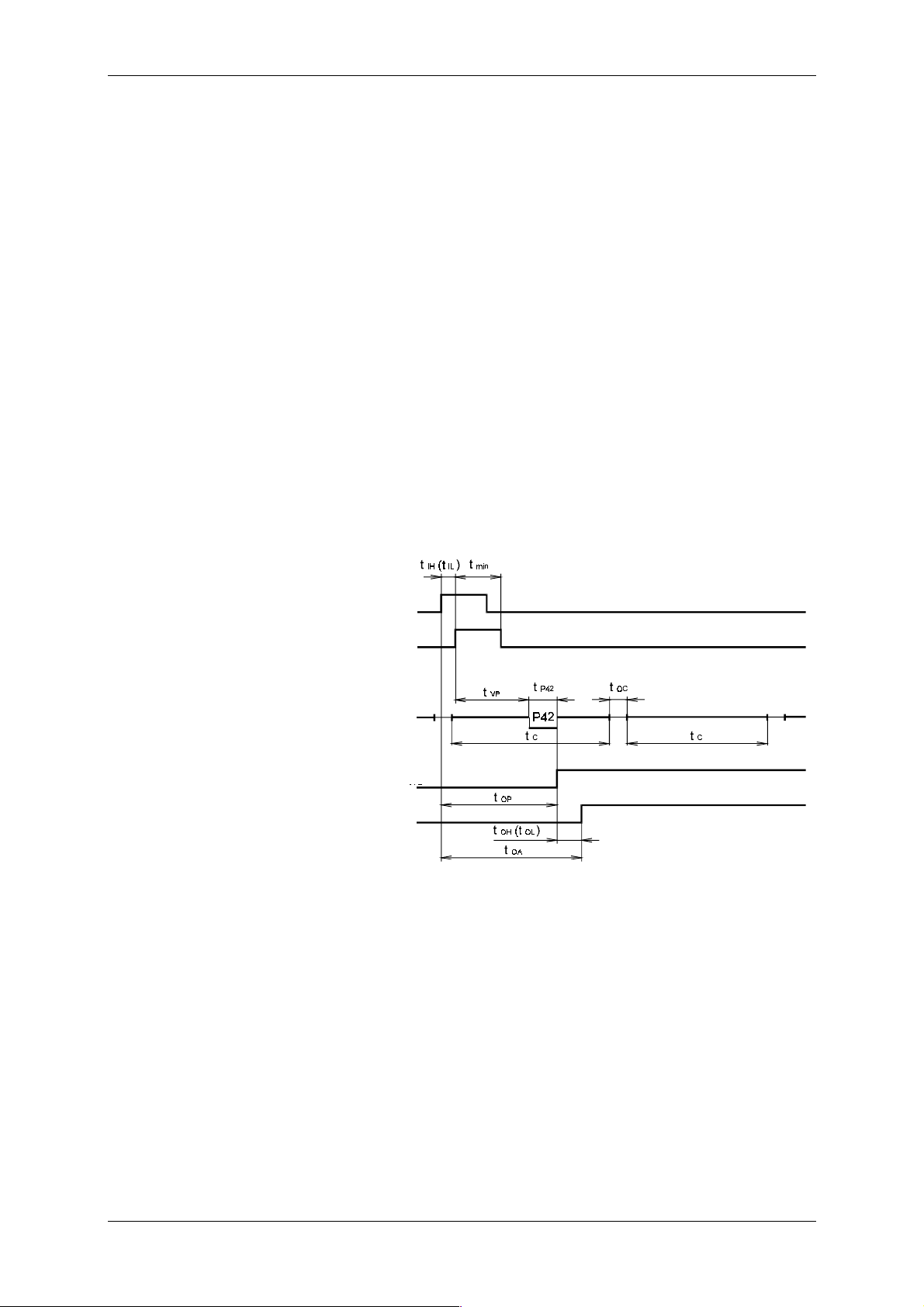
Technical equipment of TC600 PLC
Programmable
controller response
asynchronous to t he
program cycle
t
OH, t OL
- output delay
Closing ti me or opening t ime of the output switc h
- typ. 4 ms for rel ay outputs
- max . 400 s for transi stor outputs
t
t
- time of the pr ogr am response (see further text)
OP
- time of the pr ogr ammable controller response (see further text)
OA
Time diagram in Fig. 10.1 illustrates the shortest possible response time
of the progr ammable controller t
to change of signal at t he i nterr upt i nput.
OA
In the P42 process, identification of the interrupt source is performed and
servi cing of the i nterrupt by writi ng to the output physical address (see it em
10.5.12). Allowing of the interrupt from the ascending signal edge is assumed. Response time of the programmable controller is the sum of the
following times:
= t IH (t IL) + t VP + t
t
OA
+ t OH (t OL)
P42
It is apparent f rom t he tim es defini tion that t he user m ay aff ect the programm able c ontrol l er response by the progr am struct ure and by selec ti on of
the output switch t ype. For ex ample, i f t he user instruction i s placed as the
fir st or last i nstructi on in the P 0 process, in ti me t
may be appli ed. Ex ceeding of t he allowed ti me of t he i nterrupt process
t
USI
5 ms) is ev al uated by the di agnosti c system as a seri ous err or of t he
(t
P42
the sum of tim es t
VP
OC
user program (see Chapter 11).
a
Signal at
the interrupt input
Signal after
the input filter
Cyclicly executed user
program interrupted by
the P42 process
Writing of the program
response to the
memory pad
Signal at the binary
output
Fig. 10.1 Response time of the programmable controller to change of the
signal at the interrupt input at processing of the response in the
P42 process and wr iting to the output physical address
73 TXV 138 08.02
Page 74
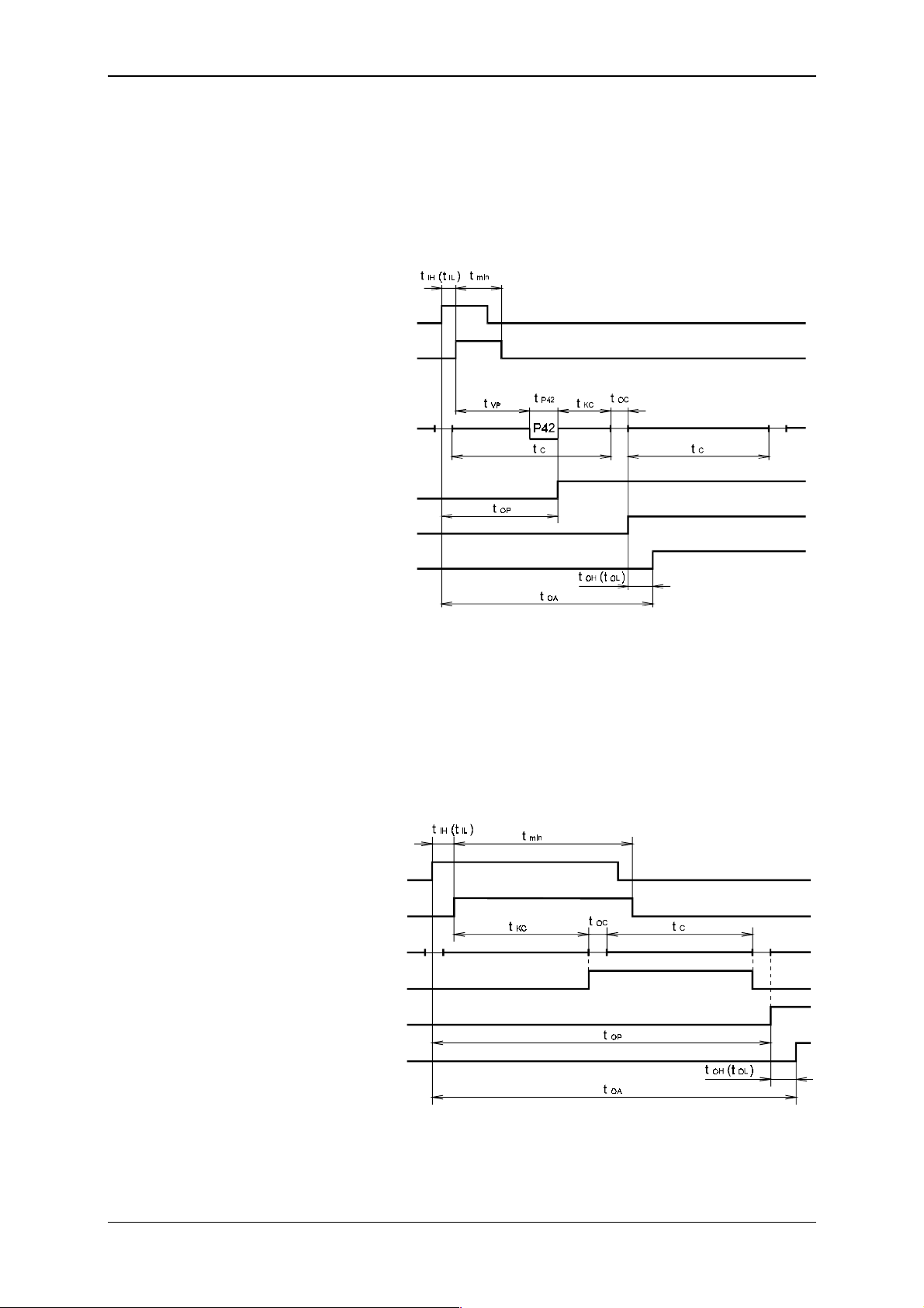
Tecomat TC600
Response of the
programmable
controller
synchronized with the
program cycle
Tim e diagr am in F i g. 10. 2 gives prolongat i on of the r esponse ti m e of t he
programmable controller to change of the signal at the interrupt input at
synchronization of the response with the user program cycle. In the P42
process, identif ication of the interrupt source is perform ed and servici ng of
the interr upt by wri ti ng to t he scratc hpad. Response tim e of the program m able controller is i n this case the following sum of times:
= t IH (t IL) + t VP + t
t
OA
Signal at
the interrupt input
Signal after
the input filter
Cyclicly executed user
program interrupted by
the P42 process
Writing of the program
response to the
memory pad
Transcription of the
response to the output
Signal at the binary
output
+ t KC + t OC + t OH (t OL)
P42
Response of the
programmable
controller at
processing of the
standard binary input
signal
Fig. 10.2 Response time of the programmable controller to change of the
signal at the interrupt input at processing of the response in the
P42 process and writing to t he scratchpad
Time diagram in Fig. 10.3 illustrates prolongation of the response tim e of
the programm able controller to change of the signal when standard binary
inputs are used (interrupt inputs in the basic m ode). Response time of t he
programmable controller i s i n this case the following sum of times:
= t IH (t IL) + t KC + 2t OC + t C + t OH (t OL)
t
OA
Signal at
the binary input
Signal after
the input filter
Cyclicly executed user
program
Transcription of the
response to the output
Writing of the program
response to the
memory pad
Signal at the binary
output
Fig. 10.3 Response time of the programmable controller to change of the
signal at the standar d binar y input
TXV 138 08.02 74
Page 75
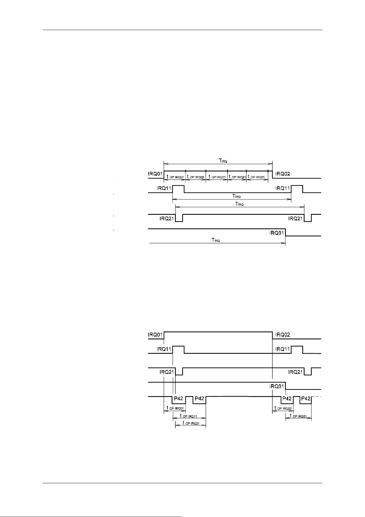
Technical equipment of TC600 PLC
Interrupt period
To determi ne the IRQ period, t hat i t , t he int erval bet ween two IRQ's f rom
the signal at one i nterrupt input, it is necessary to real ize that the IRQ from
signals at indi vi dual inter rupt inputs are asynchronous towards the program
cycle, and at the same time they may be asynchronous towards one another. If the IRQ is not to be lost, it must hold that:
t
T
IRQ
T
- interrupt per iod
IRQ
- m aximum response time of the program to the al lowed IRQ f rom
t
OP IRQ
OP IRQ
one edge of one signal
Meeting of this condition i s illustrated in Fig. 10.4. Allowing of interrupt
from the ascending as well as descending edge of the signal at DI0 is assumed, and of the ascending edge of the signal at input DI1 and descending
edge of the signal at input s DI2 and DI3.
Signal at
input DIO
Signal at
input DI1
Signal at
input DI2
Signal at
input DI3
Processing of
concurrent IRQ's
Fig. 10.4 Relation among the int errupt period, number of allowed int errupt s,
and response time of the program to individual interrupts
To servi ce concurr ence of I RQ's f rom sev eral asynchronous si gnals, t he
PLC is equipped with the IRQ buffer register. If the requirement of the
mini mum interr upt period is not met, the stack may ov erflow and t he IRQ
may be lost. This state is signalled by the error message with the code
22 00 00 00 in registers S34 and S48 to S51. G radual processing of IRQ's
and prolongati on of the response time of the program is illustrated in Fig.
10.5.
Signal at
input DIO
Signal at
input DI1
Signal at
input DI2
Signal at
input DI3
Cyclicly executed
user program
interrupted by
the P42 process
Prolongation of the
user program cycle
Fig. 10.5 Gradual proces s ing of concurrent IRQ ' s
When using inter rupt inputs, i t i s necessary to keep in m ind that ev oking
of interrupt processes causes prolongation of the program cycl e time which
may even lead to ex ceeding of t he maxi mum al lowed cycle tim e.
75 TXV 138 08.02
Page 76
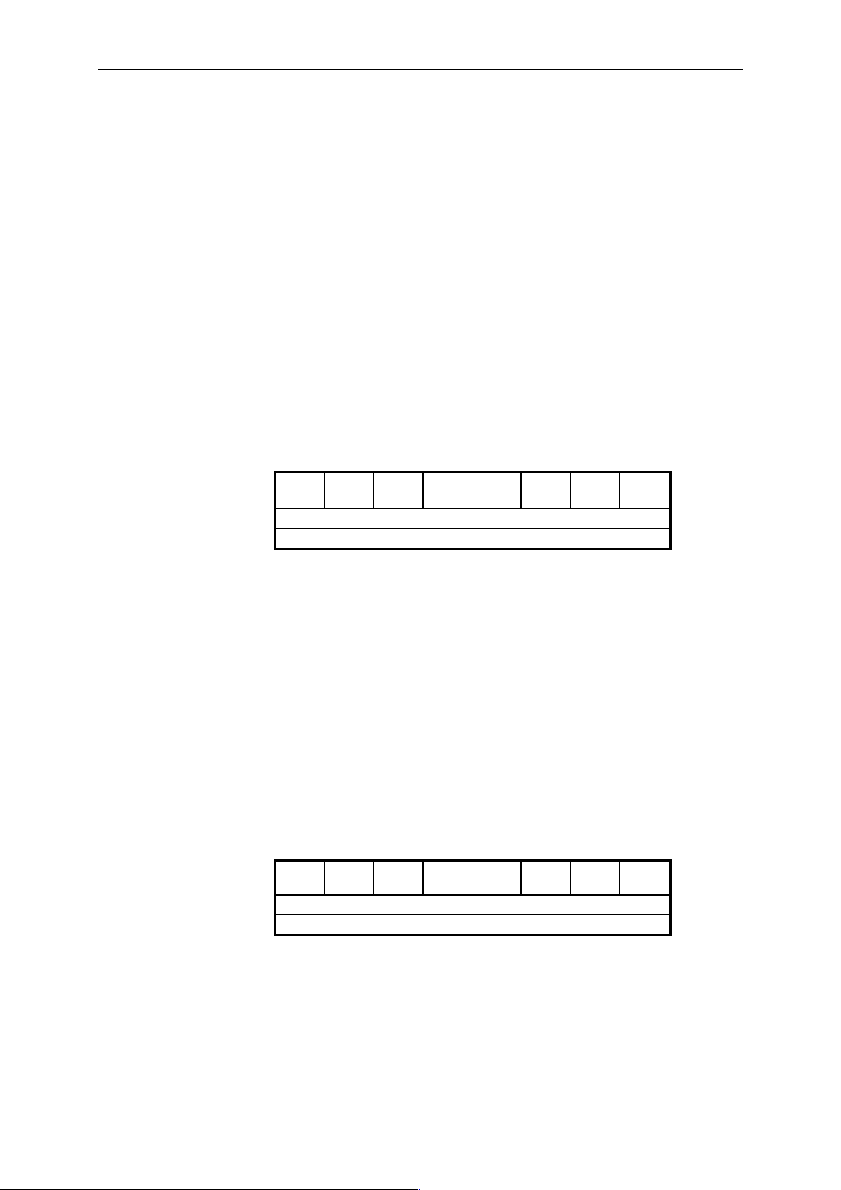
Tecomat TC600
Declaration of the
type 3 counter
10.5.9 Servicing of the Type 3 Counter
Declarati on of the counter i s perform ed by the directiv e
general structur e accordi ng t o it em 10.5. 2. P aram eter
#unit with the
INITAB of direct iv e i s
mandatory. The initialization table serves for identification of the counter
type. It c ontains one item only, c onstant 5.
Declaration example
Servicing of the type 3
counter
Image of inputs
The state word
#table byte IniCNT = 5 ;1 x unidirectional counter
;
#unit 0, 0, Count_600_, 3, 3, Xn, Yn, On, IniCNT
;
Parameter TYP of directi ve #unit is input symbolically Count_600_ or
numerically
) depends on the BM type (on oc cupation of the scrat chpad by im ages of
Yn
$30. Placem ent of the stat e and control word (param eters Xn,
inputs and outputs).
In the scratchpad m emory, the counter occupi es 3 bytes in i mage of inputs, and 3 bytes in i mage of outputs.
The STAT state word is stored in the image of inputs and the current
state of the count er. If the int errupt is allowed, im age of inputs is updated
before the P44 process is executed, i f the interrupt i s prohibited, it is updated in the cycle loop. Zone with the initial address defined by the parameter
Z_IN of dir ec tive #unit has the following structur e:
----STAT
STAT.2STAT.1STAT
.3
Less signific ant byte of the counter value
More significant by te of the c ounter v alue
Z_IN
.0
Z_IN+1
Z_IN+2
STAT.0 = 1 - reaching of t he maxi mum counter range (65535) in this cycle
STAT.1 = 1 - reaching of the pre-selection in this cycle
STAT.2 = 1 - reaching of t he maximum c ounter range
The bit i s set to zero by the zero lev el of the RESET si gnal
or from the ascending edge of bit CO NT.4
STAT.3 = 1 - reaching of t he pr e- sel ec tion
The bit is set to zero when the counter overflows, by zero
level of the RESET signal or from t he ascendi ng edge of the
CONT.4 bi t
STAT.4 - state of the RESET input
Image of outputs
Image of output s contains the CONT control word and the v alue of t he
counter pre-selecti on. State of bits CONT. 5 to CONT.7 is accepted by t he
system after writing to the scratchpad, state of other bits in CONT as well as
the pre-selection value, is accepted in the cycle loop, or at termi nation of
the P44 inter rupt pr ocess, respecti v el y. Zone wit h the i ni ti al address def i ned
by parameter
CONT.7CONT.6CONT.5CONT
Z_OUT of dir ec tive #unit has the following structur e:
Less signific ant byte of the counter pre-selec tion
More significant by te of the c ounter pre-selection
TXV 138 08.02 76
.4
---
CONT
Z_OUT
.0
Z_OUT+1
Z_OUT+2
Page 77

Technical equipment of TC600 PLC
CONT.0 - bloc k ing of t he c ounter
0 = blocking of t he c ounter
1 = counter running
CONT.4 - resetting of t he c ounter
Change of the bit state from 0 to 1 per form s reset of the
counter and setti ng to zero of all bits of the ST A T state word
(while in stat e 1, the counter is not reset). Setting of the bit to
zero is done by the user.
CONT.5 - contr ol of t he c ounter mode
0 = fr eely running counter
1 = self-filling counter with pre-selection
CONT.6 - allowing of interrupt from r eac hing of t he maximum r ange
0 = inter r upt prohibited
1 = inter r upt allowed
CONT.7 - allowing of interrupt from r eac hing of t he pr e- sel ec tion
0 = inter r upt prohibited
1 = inter r upt allowed
Counter pre-select ion
Servicing wit hin the
P44 process
Physical addressing
of the counter
The physical
address has no
automatic bond to
the scratchpad
To determ ine t he m i nim um val ue of the c ounter pr e-select i on in t he sel f filling mode and diff erence of v alues of two pre-selec tions f ol lowing one af ter another of the f r eely running counter, the following r elationship holds:
n
n - value/di ff er enc e of values of the pre-selection
f - frequency of signal at the CLK input .
For servicing within the P44 process it holds that time of the interrupt
process must not exceed 5 ms. It is also necessary to keep in mind that
evoking of interrupt processes causes prolongation of the program cycle
time which may even lead to exceeding of the maximum allowed cycle
time.
Reading of the state word, count er v alue, and writing of the c ontrol word
and counter pre-selection can be perform ed by reading from and writing to
the counter physic al address.
LD U$3000 ;reading of the STAT state word
LD UW$3001 ;reading of the counter state
WR U$3080 ;writing of the CONT control word
WR UW$3081 ;writing of the counter pre-selection
By reading from t he phy si c al address or writing to the physical address of
the counter, the corresponding change of the v alue in image of inputs or
outputs in the scrat c hpad memory does not happen!
In the case of physical r eading, val ue in image of inputs is correc ted in
the course of the cycl e loop.
In the case of phy sical writ ing, i t i s necessary to ensure the correct ion in
the scratchpad by the user program otherwise in the cycle loop t he counter
will be set according to the original value in image of outputs.
77 TXV 138 08.02
Page 78
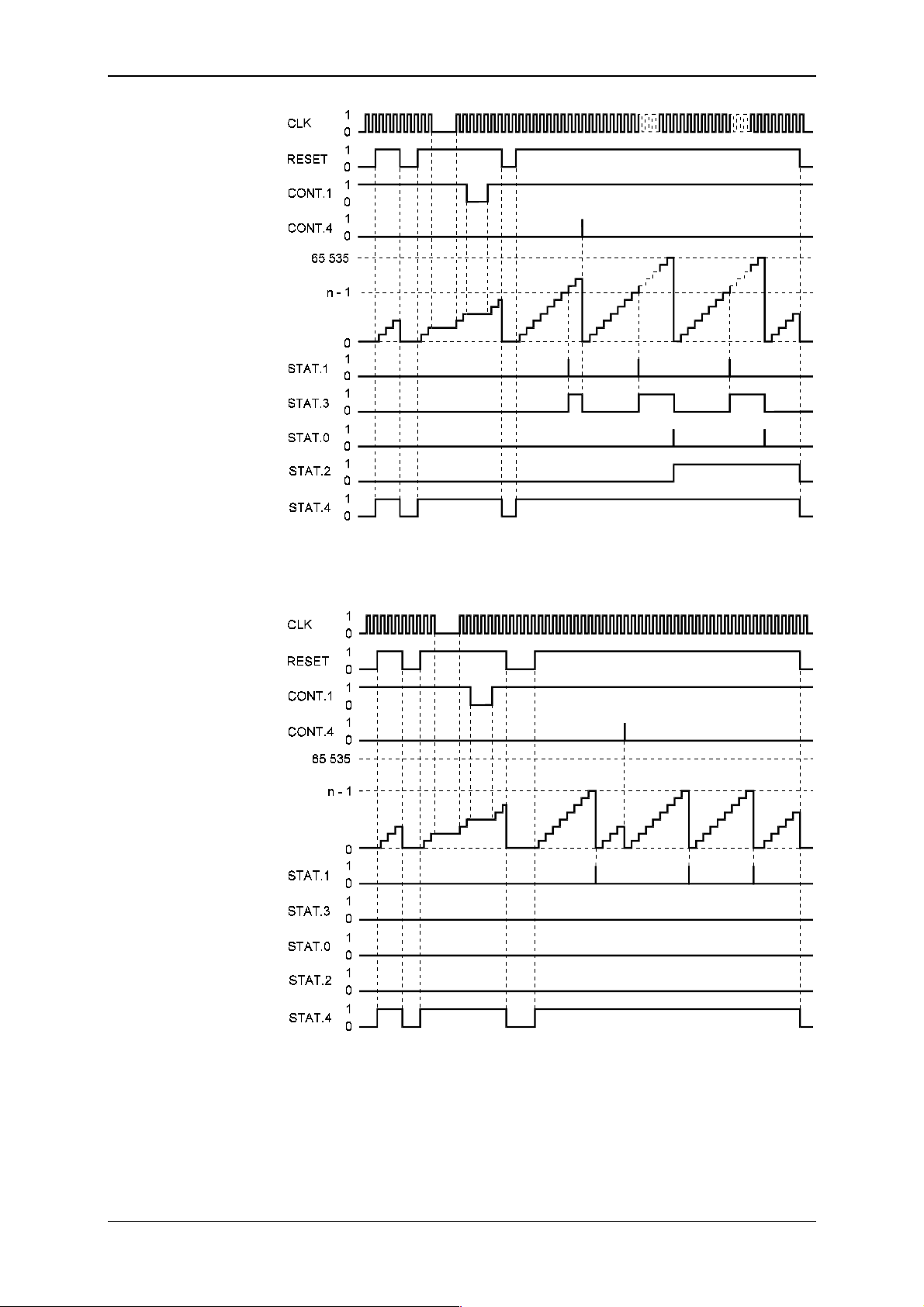
Tecomat TC600
Time diagrams of the
counter modes
counter
Fig. 10.6 Tim e diagr am of the freely r unning c ounter
counter
Fig.10.7 Time diagram of the s elf-filling counter with pre-selection
TXV 138 08.02 78
Page 79
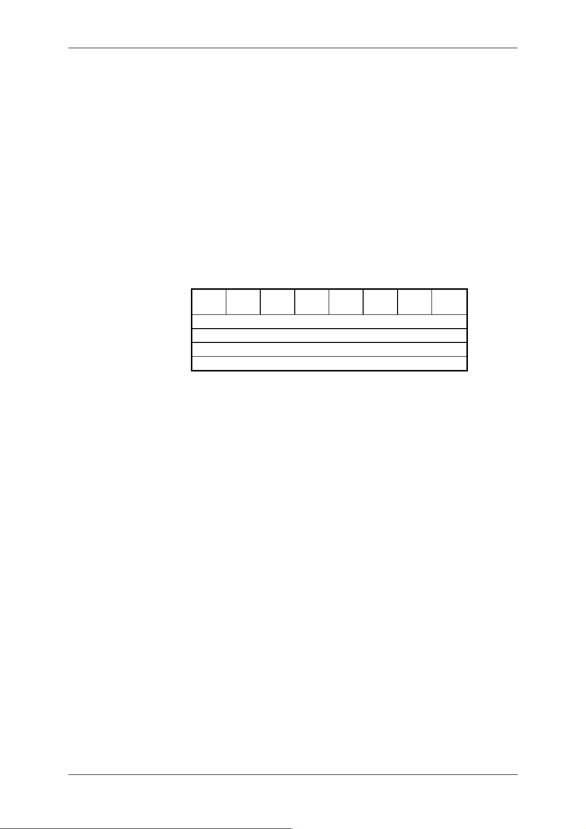
Declaration of
admeasuring
Technical equipment of TC600 PLC
10.5.10 Incremental Enco der Servicing
Declaration of admeasuring is performed by the directive
general structur e ac c or ding to it em 10.5.2.
#unit with
Declaration example
Servicing of
admeasurement
Image of inputs
The state word
#unit 0, 0, IRC_600, Xn, Yn, On
Parameter TYP, POC_IN, POC_OUT of di rectiv e #unit is input symbolically as
control word (param eters
IRC_600 or numeri cally $40, 5, 9. Placement of the state and
Xn, Yn) depends on the BM type (on occupati on
of the scrat c hpad by images of inputs and outputs).
Admeasuring occ upies the t otal of 14 by tes in t he PLC scratc hpad m em ory, 5 bytes in the image of input s and 9 byt es i n the image of outputs.
In the image inputs, t he S TAT state word is stored and the actual state of
the admeasured value. If interrupt is allowed, image of inputs is updated
before the start of the P44 process, or in the cycl e loop i f i nterrupt is prohi bited. Z one with the ini tial address def ined by the par ameter
#unit has the following structure:
STAT.7STAT.6STAT.5STAT.4STAT.3STAT.2STAT.1STAT
Z_IN of directiv e
Z_IN
.0
Least signif icant byte of the admeasured value
Z_IN+1
Z_IN+2
Z_IN+3
Most significant byte of the admeasured v alue
Z_IN+4
STAT.0 = 1 - overf low of the maxim um admeasurement range i n this cy-
cle (values 7FFF FFFFh)
STAT.1 = 1 - underflow of the mi nimum admeasurement range in thi s cy-
cle (values 8000 0000h)
STAT.2 = 1 - reaching of pre-selection for the ascending direction in this
cycle
STAT.3 = 1 - reaching of pre-selection f or the descending di rection i n thi s
cycle
STAT.4 - immedi ate movement directi on
0 = ascending (from lower val ues to the higher ones)
1 = descending (from higher v alues to the lower ones)
STAT.5 - flag of the m ode of the reference point look up
0 = passiv e mode
1 = acti ve mode
STAT.6 - reachi ng of pre-selection f or the ascending direction
0 = admeasured value below pre-selection
1 = admeasured value above pre-selec tion
The bit is set to zero at overf low of the maximum admeasurement range.
STAT.7 = - r eac hing of pre- sel ec tion f or the descending direction
0 = admeasured value above pre-selec tion
1 = admeasured value below pre-selection
The bit is set to zero at underflow of t he mini mum admeasurement range.
The admeasured
value
Admeasurement registers every edge of the phase-shifted incremental
encoder signals, that means that the admeasured val ue is the q uadruple
of the number of pulses of the generated incremental encoder's. For
exampl e, in one i ncr em ental encoder l oop wit h divi sion i nto 1250 scal e divi sions, additi on of the admeasured value is 5000.
79 TXV 138 08.02
Page 80

Tecomat TC600
Image of outputs
The control w or d
Pre-selection of the
admeasured value
Image of outputs contains the CONT control word, pre-selection of the
admeasured v alue for the ascending direct ion, and pre-selection of the admeasured value for the descending direction. State of bits CONT.6 and
CONT.7 i s accepted imm ediatel y aft er their writ ing to the scratc hpad, state
of other bi ts in CO NT as well as of t he pre-select ions is accept ed in t he cycle loop, or upon termi nation of the P44 interr upt process, respectively.
CONT.7CONT
.6
----
CONT.1CONT
Least signif icant byte of pre-selection f or the ascending direc-
Z_OUT
.0
Z_OUT+1
tion
Most significant byte of pre-sel ec tion f or the ascending direc-
Z_OUT+4
tion
Least signif icant byte of pre-selection f or the descending direc-
Z_OUT+5
tion
Most significant byte of pre-sel ec tion f or the descending direc-
Z_OUT+8
tion
CONT.0 - m ode of the reference point look up
Change of state of the bit from 0 to 1 evokes request for look
up of the reference poi nt (zero pulse). S etting of the bit to
zero is done by the user. During look up of the reference
point, the STAT.5 is set. The first zero pulse after accepting
of the request, causes setting to zero of the adm easured
value and the STAT .5 bit.
CONT.1 - adm easurement reset
Change of state of the bit from 0 to 1 evokes setting to z er o
of the admeasured value. During state 1, admeasurement is
not reset.
CONT.6 - allowing of interrupt from overflow or underflow of the ad-
measurement r ange
0 = inter r upt prohibited
1 = inter r upt allowed
CONT.7 - allowing of interrupt from r eac hing of one of the pre-selec ti-
ons
0 = inter r upt prohibited
1 = inter r upt allowed
Pre-selections for both admeasurement directions may take arbitrary
combinat ions of positiv e as well as negative v al ues. For determ ining of the
mini mum dif fer ence of t wo pre-selecti on v alues fol lowing one af ter anot her,
the following relationship holds:
n - difference of two pre-selection values following one after anot her
f - frequency of the incremental enc oder si gnal (given by divi si on of
increm ental encoder and the movement speed)
Servicing in the P44
process
In servi ci ng i n the P 44 process, it hol ds that t he ti m e of t he int errupt process must not exceed 5 m s. It is also necessary to keep in m ind that ev oking of interrupt processes causes prolongation of the program cycle time,
which may even lead to exceeding of the maximum allowed cycle time.
TXV 138 08.02 80
n
Page 81
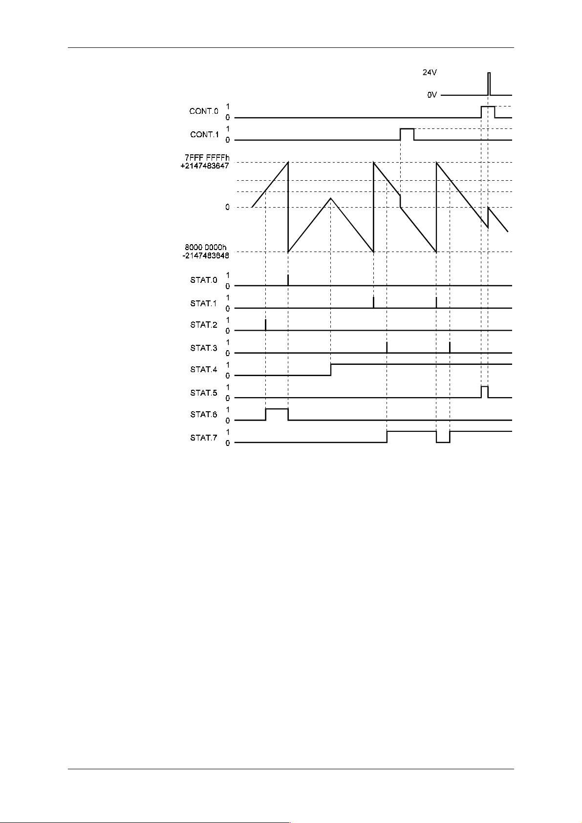
Pre-selection for the
descending direction
Pre-selection for the
descending direction
Admeasured
value
Technical equipment of TC600 PLC
Zero IRC pulse
Function declarat ion
Declaration example
Servicing of the
function
Fig.10.9 Tim e diagr am of admeasuring using increm ental encoder
10.5.11 Measurement of the Signal Period and Phase Shift
The function declar ation is performed by the directiv e
#unit with general
structure according to it em 10.5.2.
#unit 0, 0, Period_600, Xn, X_On ;measurement of the TC600
;period and phase shift
Parameter TYP, POC_IN, POC_OUT of di rectiv e #unit is input symbolically as
Period_600 or numerically $50, 2, 0 .
Placement of the function output (parameter
Xn) depends on the pro-
grammable controller type (occupation of the scratchpad by images of inputs and outputs).
Both measurement modes occupy in the image of inputs of the PLC
scratchpad mem ory 2 bytes at address defined by the param eter
rective
#unit. A content of the im age is updated in the user program cycl e
Xn of di-
loop.
In measurement of the signal period, these 2 bytes hav e the m eaning of
the number of cycles of the internal clock signal per 1 period of the measured signal. In measurement of the phase shif t, they have t he meaning of
the number of cycles of the internal clock signal between two descending
edges of the m easured signals.
81 TXV 138 08.02
Page 82
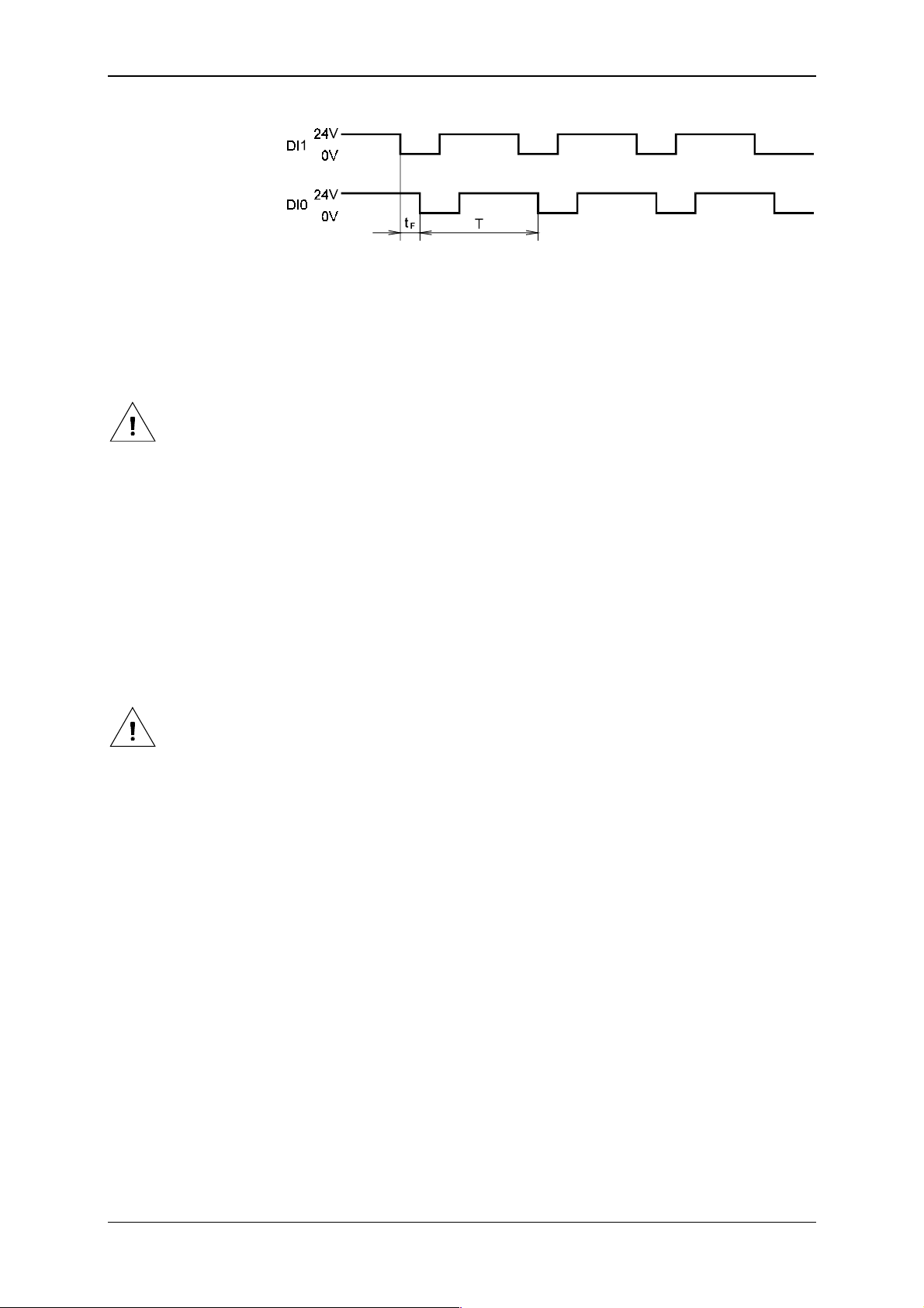
Tecomat TC600
Graphic illustration of
time of the period and
phase shift
T signal period time at BM input DI0
t
F
phase shift of signals at BM inputs DI1 and DI0
Measurement mode
control
Period measurement
Control of the measurem ent mode is done by a program using t he i m age
of the binary output DO 0 of BM (by image Yn. 0) .
If the bit Yn.0 = 0, m easurement of the signal peri od is perfor med at input DI0 of BM, i f t he bit Yn. 0 = 1, m easurem ent of t he phase shif t of signals
between inputs DI1 and DI0 of BM is performed.
Physical output DO0 of BM can be used only f or indicati on of the f unction m ode.
In signal period (f requency) measurement, it is possible to measure the
signal withi n the frequency of about 1 Hz t o 1 k Hz . The measured number of
cycles of the clock signal then reaches values of 32767 to 33. The value
65535 signals exceedi ng of t he m easurement range (i t corresponds with the
input signal f requency lower than 1 Hz , or possibl y with a non-connect ed input).
For conversi on of the num ber of cycl es of the i nternal cl ock signal t o t he
tim e information, the following rel ationship holds:
T [µs] = n x 30.5175
T signal period time at input DI0 of BM
n cont ents of two bytes of the scratc hpad determi ned by the parame-
Xn of dir ec tive #unit
ter
In the case of measurement of a sine alternating signal period,
doubling of frequency occurs at the input circuits (two-directional rectifying) and the measured period value corresponds with the half of its
real value at input DI0 of BM.
Example of the period
rectificat ion
#program period
;
#unit 0, 0, Digit_600, 2, 2, X0, Y0, On ;binary inputs
#unit 0, 0, Period_600, X2, X_On ;period meter
;
#def Time XW2 ;signal period in clock
cycles
#def cons1 30.5175 ;const. of conversion cycles -> µs
#def cons2 0.000001 ;const. of conversion µs -> s
;
#reg float Period, ;signal period in µs
Frequency ;signal frequency in Hz
;
P 0
LD 0
WR Y0.0 ;period measurement
;
LD Time
UWF
MUF cons1
WR Period ;period in µs
;
TXV 138 08.02 82
Page 83

E 0
Technical equipment of TC600 PLC
LD 1
UWF
LD Period
MUF cons2
DIF
WR Frequency ;frequency = 1 / period
Phase shift
measurement
Example of the phase
shift measurem ent
Measurement of the phase shift is used for signals with the same frequency. The ti m e di f f er ence between descending edges of two diff erent signals connected to inputs DI1 and DI0 of BM is measured. The m easured
number of cycles of the clock si gnal then reaches values of 1 to
.
For conversi on of the num ber of cycl es of the i nternal cl ock signal t o t he
tim e val ue, the following rel ationship holds:
[µs] = n x 30.5175
t
F
t
F
phase shift of signals at i nputs DI1 and DI0 of B M
n cont ents of two bytes of the scratc hpad determi ned by the parame-
Xn of dir ec tive #unit
ter
In the case o f measurement of p hase shift o f alternating signals, it
is necessary to rectify the signals in single wave.
#program phase
;
#unit 0, 0, Digit_600, 2, 2, X0, Y0, On ;binary inputs
#unit 0, 0, Period_600, X2, X_On ;phase meter
;
#def Time XW2 ;signal phase shift in clock
cycles
#def cons1 30.5175 ;const. of conversion cycles -> µs
;
#reg float Phase ;signal phase shift in µs
;
P 0
;
E 0
LD 1
WR Y0.0 ;phase shift measurement
LD Time
UWF
MUF cons1
WR Phase ;phase shift in µs
Physical addressing
Reading of the immediate value of the meter of frequency and phase
shift c an be done by r eading with the physic al address:
LD UW$5000 ;reading of the value of the meter
;of frequency or phase shift
83 TXV 138 08.02
Page 84

Tecomat TC600
Structure of the
physical address
Use of the physical
address in the U
operand
10.5.12 Physical Addresses of Inputs and Outputs
Physical address of binary and analog inputs and outputs has the following structure:
address upper byte address lower byte
A15 A14 A13 A12 A11 A10 A9 A8 A7 A6 A5 A4 A3 A2 A1 A0
A15 to A12 - type of input and output (f ixed-given)
1000 ($8) - binary inputs and outputs
1001 ($9) - binary inputs and outputs
1010 ($A) - binary inputs and outputs
1101 ($D) - analog i nputs and outputs
other combinations are reserved
A11 to A8 - m odule type
0 - BM
1 - first EM/2
2 - second EM/2 or EM
A7 - addr ess type
0 - input address
1 - output address
A6 to A0 - number of the input or output PLC byte
The physical address is entered immediately after the U operand (or
UW, respectively) , always in the hex adec imal form .
LD U$A000 ;direct reading of state of 8 bin. inputs
;(byte 0)
LD UW$A000 ;direct reading of state of 16 bin.
;inputs (byte 0,1)
WR UW$A080 ;direct writing of the value of 16 bin.
;outputs (byte 0,1)
Physical address
has no automatic
bond to the
scratchpad
Procedure for t es ting
of correct c onnec tion
of input and output
signals
By reading from t he phy si c al address or writing to the physical address of
inputs and outputs, t he correspondi ng change of value i n i m age of i nputs or
outputs in the scrat c hpad memory does not happen!
In the case of physical r eading, val ue in image of inputs is correc ted in
the course of the cycl e loop, and usually this is faulty (however, it must t o be
taken into ac c ount).
In the case of phy sical writ ing, i t i s necessary to ensure correcti on in the
scratchpad by the user program, otherwise in the cycl e loop t he outputs will
be set according to the original v alue in the image of outputs.
Another possibility is to turn off servicing of PLC outputs in the software
confi gurati on i n the c om pil er at com pi l ati on of t he user program (i tem of t he
directiv e
#unit
) and servi ce the outputs ex clusiv ely by di rect writi ng using
the U operand and the physical address.
10.6 Testing of Input and Output Signals
For testing of input and output signals connected to the PLC, it suff ices
to create an empty program containing only sw confi guration of the t ested
PLC and instructi ons P0 and E0 which create an empt y basic process. Af terwards it is possible t o observe stat es of the connected inputs using debugging means of the dev elopm ent env i ronm ent and set arbit rary v al ues at
the PLC outputs. This very simple but very efficient procedure is recommended to be used bef ore debugging of one' s own user program as in this
way the whole route fr om input elem ents (end switches, ...) through inputs
and to the PLC scratchpad m em ory is v eri fi ed in adv ance, as well as backwards, from the scrat chpad memory t hrough outputs and to the acti on elements. Errors arisen fr om connecting of the PLC to the controlled object can
be remov ed in t his way, f indi ng of which i s usuall y m uch m ore c ompl icated
in the phase of debugging of t he c ontrol program.
TXV 138 08.02 84
Page 85

Reduced instruction
set
Standard instruc tion
set
Extended instruc tion
set
Technical equipment of TC600 PLC
10.7 Instruction Set
The set of instruc ti ons and system services of PLC' s of t he TC600 seri es
is compatible with other Tecomat PLC's. The central unit of the D series
contains the ex tended instruction set which, besides instructi ons of the reduced and standard instruct ion set, contai ns instructions designed f orm t he
most ef ficient PLC's.
The following are parts of the reduced i nstr uc tion set:
bit logical oper ations
basic operations of counter s and timers
basic organi z ational instructions and tr ansfers in the program
compar ison in the ex tent of a word
one-loop control
Compared to the reduced instruction set, the standard instruction set
contains the following in addition:
logi c al operations i n the extent of a byte and word
ext ended oper ations of counters, timers, shif t registers
arithmetic instructions, conversions and comparison in the extent of a
word
ext ended or ganizational instruct ions, transfer s i n pr ogr ams
t able instructions abov e tables in the user memor y which allow for opt i-
mum realization of even very complicated combination and sequence
functi on blocks, decoders, time and sequence control lers, sequence ge-
nerators, furthermore they make easier realization of diagnostic func-
tions, recognit ion of error states, sequence records of ev ents, protocols
about the process, diagnostic messages of the t y pe " black box"
tabl e instructions abov e the space of v ariables allow f or operation with
indexed v ariables, reali zation of the del ay line, l ong shift register s, con-
versi ons to the code " 1 of n", select i on of variabl es, step cont rol ler s, rec -
ords of events and v ar ious stack structures
instructions of t he sequence controller
instr uctions realizing t he set of l ogical operations, i ncluding counti ng of
ones bits in the operand of the word type. In this way it is possible to
easily realize the majority and general threshold functions, parity f unc-
tions (MOD 2), and arbitrar y symmetr ic func tions
8 user stacks and instructions for t heir switching which al low for t ransfer
of more parameters among functions which do not follow immediately
one after the other, storing of the immediate state of the stack, etc.
automatic conv ersion of the l ength of operands and i ntermedi ate results
in combination of bit, byte and word instructions or logical instructions
with arithmetic ones
system vari ables in whic h the system t im e is reali zed, system tim e uni ts
and their edges, com muni cati on v ariabl es, f lag and c omm and v ari ables,
system messages
multiprogramming (multi-loop control) including interrupt processes
which contribut es to shortening of the response ti me as well as to easier
programm ing
user i nstructions USI which real ize in the opti mum way (on the l evel of
the mi croprocessor instructions) com plex tasks (special communi cation,
regulation, t ime-crit ical user tasks)
Compared to the standard instruction set, the extended instruction set
contains the following in addition:
logi c al operations i n the long extent
arit hmetic instructi ons, c onversions and comparisons in the long extent
condit ional jumps according t o the comparison flags
arit hmetic instructi ons i n the format with the float ing point
ext ended table instruc tions with tabl es of large extent
table instructi ons with str uc turaliz ed ac c ess
instructions of t he P ID regulator
85 TXV 138 08.02
Page 86

Tecomat TC600
The PLC diagnostic
system
Full descript ion of the instruction set i s giv en in t he handbook
Set of Tecom at PLC, TXV 001 05.02
Instruction
11. Diagnostics and Removal of Faults
The Tecom at PLC di agnosti c system i s a part of t he standard sw and hw
equipment of the PLC's. It is active starting from turning on of the PLC
power supply and operates independentl y of the user. T he main funct ion is
ensuring of error-free and accurately defined function of the PLC in any
situation. The system continuousl y follows v itall y important parts and functions of the PLC and ensures serv icing of an error state i mm ediately in the
moment of i ts occurrence and informs about the faul t.
In the case a fault ari ses within the P LC, the di agnostic system must especially eliminate the possibility of origination of breakdown states in the
technology connec ted to the PLC.
Another task of the diagnostic system is to make easier remov al of the
arise fault to service workers or to t he user, r espect iv ely.
Besides basic functions, the diagnostic system notifi es the user of any
possible erroneous mani pulati ons or procedures at the PLC at tendance due
to which working with t he P LC bec omes easier and more eff icient.
11.1 Conditions for Proper Function of the Diagnostics
The basic condition for error-free function of the PLC and proper operation of it s diagnostics is proper functi ons of the power supply and of the
central unit.
After turning on of the supply, basic checking of the system kernel is
perform ed wit hin t he i nit i ali zat i on. I f an error of the E PROM or RA M system
memory is found, the diagnostic system cannot continue in its operation.
This state is signalled by lighting t he letter E or t on the display.
Error stacks
Indication of errors
PLC behaviour in the
case of a serious
error
11.2 Indication of Errors
The central unit is equipped with t he main error stack whic h contains 8
last error codes announced by the diagnostics of the whole PLC and a l ocal
stack containi ng 8 last error codes announced by t he diagnostics of serv icing of inputs, outputs, and c ommunication t hr ough the serial channels.
Full er r or c ode in the main error stack is 4 bytes long. The first byte gives
the basic error code ( it deter m ines the gr oup of f aul ts), the f ol l owing 3 bytes
give close specification of the er r or .
Full er r or c ode in the local error stack is 2 bytes l ong. The first byte giv es
the basic error code (it determines the group of faults), the second byte
gives closer specif ication of the error .
Contents of bot h error stacks are av ai labl e from t he x PRO dev elopm ent
envi ronment. Codes of serious errors are shown on the display at the moment of their eval uation in t he form at:
E -label followed with t he full error code in hexadecimal form
80 - basic error code
09 00 00 - closer error specification
11.3 Serious Errors
In the case of the rise of a serious error, the di agnostic system blocks the
outputs fi rst, inter rupts executi on of the user progr am, and then i t identi fies
the arisen fault. The ful l error code i s shown on the display and stored i n the
main error stack.
Indicati on of such an error can be cancell ed by a comm and f rom t he superior system or by turning off and on of the PLC power supply.
TXV 138 08.02 86
Page 87

Technical equipment of TC600 PLC
The fol lowing abbrev iati ons and terms are used in the ov erv iew of error
codes:
PC - address of instructi on in which the error oc c ur r ed ( pr ogr am counter)
AM - activation of inputs and outputs:
$40 = acti vation of inputs
$80 = acti vation of out puts
$C0 = acti vation of inputs and outputs
AJ - upper byte of the physical address of input s and outputs at which
the error occurred
$12 = serial c hannel CH2
$13 = serial c hannel CH3
$81 = binary inputs and outputs of the fi r st E M /2 (TC631, TC632)
$82 = binary inputs and outputs of the second EM/2 (TC631,
TC632)
$91 = binary inputs and outputs of the fi r st E M /2 (TC633)
$92 = binary inputs and outputs of the second EM/2 (TC633)
$A0 = BM bi nar y inputs and outputs
$A2 = EM bi nar y inputs and outputs
$D0 = BM analog inputs and outputs
$D1 = analog i nputs of the first EM/2
$D2 = analog i nputs of the second EM/ 2 or E M
Map of the user progr am
- main cont r ol structure generated by the com piler.
Numeric al codes are given in the hexadecimal form.
Errors of storage of
the user program
11.3.1 User Program Errors
80 01 00 00 wrong length of the user program map in the EEPROM
source memory
80 02 00 00 wrong ensuring charact er ( CRC) of the user pr ogr am map in
the EEPROM source memory
80 03 00 00 wrong ensuring charact er ( CRC) of the whole program i n the
EEPROM source memory
80 04 00 00 user program is not in the EEPROM source memory
Fault in the EEPROM source memory has occurred, the
user program is designed f or another series of central unit s
or it has not been recorded in the EEPRO M at al l. It is necessary to load a new user program in EEPROM or disconnect the EEPROM memory and load the user program in
the RAM memory.
80 05 00 00 wrong length of the user program map in RA M
80 06 00 00 wrong ensuring charact er ( CRC) of the user pr ogr am map in
RAM
80 07 00 00 wrong ensuring character (CRC) of the whole program in
RAM
A faul t in the memory has occurr ed. It is necessary to load a
new user program in RAM.
80 08 00 00 editing intervention in the user program while the EEPROM
source memor y has been connected
If the EEPRO M memory is connected, af ter turning on the
system its contents is loaded in the RAM memory of the
central unit . The central uni t check s integri ty of the program
copy from EEPROM. In the case of editing intervention, it
announces the error Edit i ng int erventi on, and i t is necessary
to disconnect the EEPROM mem ory or re-program it . If t he
editing intervention has been unwanted, it is sufficient to
turn off the PLC and turn i t on again, and the origi nal pro-
gram will be loaded from EEPROM.
87 TXV 138 08.02
Page 88

Tecomat TC600
Programming errors
80 09 00 00 the program has been com pi l ed f or anot her series of cent ral
units
The compi l er was set for anot her series of cent ral unit s. It i s
necessary to select the correct series of central units in the
compiler menu (the series is marked by a capital letter in
the name of the cent ral unit ) and compil e the user program
again. If t he com pi l er was set correctl y, then t his com pi l er is
designed for hi gher version of the system sw than the v er-
sion fi tted in the central unit of your PLC. T his dissonance
must be removed either by using an older version of the
compiler or by ex c hanging of t he system sw in the CPM.
80 0A 00 00 at t empt to program a non-existent EEPROM
The memory is not fitt ed or is disconnected.
80 0B 00 00 programming of EEPROM was unsuccessful
80 0C 00 00 fai lure of the RTC real t ime circuit
The real time circuit is not functions the consequence of
which is fai lure of all time funct ions of t he PLC. The m ost
likely fault is discharge of the backi ng battery which must be
exchanged. If the backing batt ery is not discharged, an ex -
pert repair of the cent r al unit is necessary.
80 0F 00 00 memory of CPU param eters cannot be program med
80 0F 01 00 memory of CPU param eters cannot be retrieved
80 10 PC PC overflow of the stac k of return addr esses
The maxi m um num ber of nested subprogram s has been ex-
ceeded. Nesting m eans call ing of another subprogram f rom
within the subprogram being alr eady executed.
80 11 PC PC underflow of the stack of r eturn addresses
Return instruction from a subprogram (RET, RED, REC)
was not preceded by call ing of t he subprogram (CAL, CA D,
CAC, CAI).
80 12 PC PC non-zero stack of return addresses after t he process termi -
nation
In the user program , there is a dif ferent number of instruc-
tions of calling of the subprogram (CAL, CAD, CAC, CAI)
than return instructions from the subprogram (RET, RED,
REC).
80 13 PC PC l abel not declar ed
The instruction of j ump or calling with a label number has
been used which is not used anywhere in the user program .
80 14 PC PC the label num ber is greater than the maximum val ue
Number of label of an instruction of jump or calling is
greater than the gr eatest number of label used in the user
program.
80 15 PC PC table T not declared
Table T used in this instruction has not been input in the
user program. I t must be added.
80 16 PC PC unknown instruc tion code
The used instruction is not implem ented in thi s cent r al unit.
80 17 PC PC i r r egular user instruct ion USI
The user instructi on is int ended for another series of central
units or it s structure is broken.
80 18 PC PC the r equested user instruction US I does not exist
The requested user instructi on USI is not connected to the
user program.
TXV 138 08.02 88
Page 89

Errors of sw
configuration
Technical equipment of TC600 PLC
80 19 PC PC error of BP i nstr uc tions nesting
The BP instruc tion cannot be used in processes P50 to P57
(calli ng of the debugging pr ocess P5n in another P5m pro-
cess).
80 1A PC PC process for servici ng of the BP is not programmed
The debugging process P5n called by the BP instruc tion is
not programm ed. It is necessary to add it to the user pro-
gram.
80 1B PC PC wrong configur ation of table T
The checksum of val ues of table T used by t his instruct ion
does not agree. The user program must be loaded again.
80 30 00 00 exceeding of t he maxi mum cycle tim e
The cycle time has been longer than t he input value.
80 31 00 00 exc eeding of t he maximum interrupt pr oc ess ti me
Executi on tim e of the i nterrupt proc ess has exceeded 5 m s
or the cycle time has been exceeded in the course of the
interrupt pr oc ess exec ution (see error 80 30 00 00).
11.3.2 Errors in the Peripheral System
81 00 30 AJ
30 AJ ex c eeding of t he number of by tes in the PLC
Greater number of bytes has been input i n the user progr am
sw configurati on than the PLC actual ly occupi es. This ent ry
must be corrected and the corrected program must be
loaded in the P LC again.
81 00 31 AJ
31 AJ initialization table i s missing
Initialization table is missing in the user program, which is
necessary for servici ng of some ty pes of t he PLC i nputs and
outputs (for exam ple, anal og input s, special f unct ions, etc. ).
This table must be added to the user program and the cor-
rected program must be loaded in the PLC again.
81 00 32 AJ
32 AJ unknown serv icing
The central unit cannot serv ice this type of the PLC inputs
or outputs. The system program m ust be exchanged f or a
newer version (the v ersion number c an be found out either
in the xPRO program or from t he PLC display aft er turning
on of the power supply).
81 00 33 AJ
33 AJ odd num ber of bytes for analog inputs
In the user program sw configuration, an odd number of
bytes has been input f or analog inputs which is not allowed
because one input takes two bytes. T his entry must be cor-
rected and the corrected program must be loaded in the
PLC again.
81 00 34 AJ
34 AJ wrong number of bytes of the ini tialization t able
The init iali zation tabl e has a diff erent num ber of bytes than
its servi cing requires. The table must be cor rected and the
corrected user program must be l oaded in the PLC again.
81 00 35 AJ
35 AJ overfilling of the initialization zone
89 TXV 138 08.02
Page 90

Tecomat TC600
Errors of inputs and
outputs during
operation
Errors of hw
configuration
A part of m emory in the centr al unit reserved f or initi aliza-
tion data of the given type of inputs or outputs has been
overfilled.
81 00 36 AJ
36 AJ number of the initialization table is greater than the maxi-
mum allowed value
Number of the ini tializat ion table is great er than the central
unit allows. The table number must be corrected and the
corrected program must be loaded in the PLC again.
81 00 37 AJ
37 AJ wrong conf iguration of the i nitialization table
The checksum of values of the i nitiali zation table does not
agree for this type of inputs or outputs. The user program
must be loaded again.
81 EM 38 AJ
38 AJ wrong entry in the ini tialization t able
There is a wrong entry in the i nitialization table. At initiali-
zation of serial channels, thi s is usually due to exc eeding of
the maximum allowed value of a parameter (for example,
length of the transmitted data) .
81 00 40 AJ
40 AJ inputs did not report themselves
PLC inputs stopped to report themselves. T he likely c ause
is a faul t at the address decoder of the i nput and output unit
or the connection with the CPU i s faulty.
81 00 41 AJ
41 AJ output s di d not report themselves
PLC outputs stopped to report themsel v es. The li kely cause
is a faul t at the address decoder of the i nput and output unit
or the connection with the CPU i s faulty.
81 00 43 AJ
43 AJ use of non- existent inputs or outputs
Servicing of non-existent inputs or outputs has been run.
The most likely cause lies in co-operation of the superior
PC's programming soft ware and the P LC c entral unit.
81 00 61 00
61 00 overflow of the zone for inputs configurat ion
81 00 61 01
61 01 overflow of the zone for outputs configuration
These errors are caused by too large number of types of in-
puts or outputs written in the sw configuration in the user
program. The max i m um number s are 16 types of i nputs and
16 types of outputs includi ng special f unc tions.
82 06 AM AJ error of configuration
A declared ty pe of input s or out puts has not been found.
11.4 Other Errors
In the case of originati on of som e of ot her error s which do not essential l y
aff ect the control i tsel f , t he di agnostic system onl y i dent ifies the ari sen f aul t,
announces the basic error code in the S34 register , and the full error c ode in
registers S48 to S51, and control of the process runs further. The i nformation can be used f or user t r eatment of these errors.
The error can al so be found by reading of the error stack into the superior system (PC).
TXV 138 08.02 90
Page 91

Errors of the serial
communication
protocol
Technical equipment of TC600 PLC
11.4.1 Errors of Seri al Communi cat ion
This group of errors is written onl y to t he local stack without t he possibility of ev aluation by the user program.
10 05 wrong start delimiter
11 05 SD parity error
11 06 LE parity error at SD2
11 07 LER parity error at SD2
11 09 DA parity error at SD2
11 0A SA parity error at SD2
11 0B FC parity err or at SD2
11 0C RB parity er r or at SD2
11 0D DAT parit y er r or at SD2
11 0E CHS par ity error at SD2
11 0F ED parity error at SD2
11 10 DA parity error at SD1
11 11 SA parit y error at SD1
11 12 FC pari ty error at SD1
11 13 CHS parity error at SD1
11 14 ED parity error at SD1
12 07 different value of LE and LE R - S D2
13 08 different value of SD and S DR - S D2
14 0A extended address SA - cannot be proc essed- SD2
14 11 ext ended addr ess SA - cannot be processed- SD1
15 0B err or of recei vi ng flag F CF in control byte FC - S D2
15 12 error of receiving flag F CF in control byte FC - S D1
18 0E wrong checksum CHS - SD2
18 13 wrong checksum CHS - S D1
19 0F wrong end deli miter E D - S D2
19 14 wrong end delimiter E D - S D1
These errors are caused by excessive disturbances of the
serial comm unicati on. They cause loss of t he message and
the consequence of t heir more f requent occur rence is even
disconnection of the communi c ation.
Error 10 05 or some of errors of group 11 m ay arise on the
one-tim e basis at establishment of communi cation with the
superior system in the middl e of a message being t ransmitted by this system. If such errors no more occur in the
course of further communic ation, everything is correct .
Errors from the CH2 serial channel have the value of the
second byte increased by 20 (for example, error 10 25,
etc.).
20 FC wrong control by te in com bination wit h a global address
2X RB unknown communication function (X is the value of the
control byte FC - 3, 4, 5, 6, 9, C, D, E , F)
The PLC does not know the requested com m uni cat i on func-
tion. T he system program must be exchanged f or a newer
version (version number can be found either in the xPRO
program or on t he PLC di splay af t er turni ng on of the power
supply).
System errors
11.4.2 System Errors
Using registers S34 and S48 to S51, these errors can be treated as
needed by the user program.
07 00 00 00 error at c hec k ing of t he r emanent zone
The backed part of the scratchpad, the so called remanent
zone, has wrong checksum. Col d restart will be performed.
The cause is a fault in backing of the RA M user mem ory on
the central unit, the most likel y fault is at the backing battery.
91 TXV 138 08.02
Page 92

Tecomat TC600
Programming errors
08 00 00 00 exceeding of t he first l imi t of guarding the cycle ti me
The cycle time has been longer than t he set warning value.
09 00 00 00 wrong system time of the RTC ci r c uit
The current t ime must be written from t he superior system.
11.4.3 User Program Errors
These errors can be treated as needed in the user program either by
elim inati ng the cause by check ing i nput param eters befor e execut ing of the
given instruction or by treat ing the consequence.
10 00 00 00 divisi on by z er o
Divisor in the div ision instruction equal t o 0.
11 00 00 00 initi al index for WMS i nstr uc tion lies outside of t able T
WM S instruct i on has a wrong parameter and therefore it wil l
not be execut ed.
12 00 00 00 initial index for LMS instr uc tion lies outside of t able T
LMS instruct ion has a wrong parameter and ther efore it will
not be execut ed.
13 00 00 00 table instruction above the scratchpad has exceeded its
range
Table defi ned by the table i nstruction abov e the scrat chpad
has exceeded its range. Instruction will not be executed.
14 00 00 00 source block of data defined outside of the range
Source block of data f or the mov e instr uction has been defined out side the range of the scratchpad, data or tabl e. Instruction will not be executed.
15 00 00 00 target block of data defi ned outside of t he r ange
Target bloc k of data f or the mov e instructi on has been defined out side the range of the scratchpad or table. Instruction will not be executed.
Checking of the PLC
11.4.4 Errors in the Peripheral System
22 00 00 00 overflow of the i nternal stack from interrupt inputs
40 00 50 00 overloaded outputs
11.5 Solution of Communication Problems with the Supe-
rior System
Connection of t he PLC to a superi or system , usual ly a PC, i s a necessit y
as every PLC must be programmed. Possible problems and way of their
analysis is indicated on the following lines.
1. Is the power supply led to the PLC?
No Correct the situation.
Yes
2. Has the PLC passed the starting sequence and is in the RUN mode
or HALT?
(see Article 10.3)
No An error has occurred in testing of the system ker nel, com munica-
tion is not possible, it is necessary to repair the P LC.
Yes
3. Do you want to program the PLC using t he xPRO dev el opment env iron-
ment?
No Continue at item 5.
Yes
4. Do you use channel CH1 f or programming?
TXV 138 08.02 92
Page 93

Checking of the serial
interface conver ter
Technical equipment of TC600 PLC
No CH1 must b e used fo r the PL C pro gramming, correct th e situa-
tion.
Yes Continue at i tem 6.
5. Do you use channel CH1 f or connection?
No Continue at item 10.
Yes
6. Do you use the standard-fitted CH1 RS-232 interface for communica-
tion?
No Continue at item 9.
Yes
7. Do you use CH1 output at connector L?
No CH1 RS-232 interf ac e is led out to connec tor L, correct the situa-
tion.
Yes .
8. Do you use the interconnection cable TXK 646 51.06?
No Check connec tion of y our c able.
Yes Continue at i tem.
9. Do you use CH1 output at terminal board K?
No CH1 optional interface is led out to terminal board K, correct the
situation.
Yes Continue at i tem 11.
10. Do you use CH2 output at terminal board N?
No CH2 interface is led out to t er minal boar d N, correct t he si tuation.
Yes .
11. Are parameters of t he relevant channel set properly?
No Set the parameter s (see Art icle 4.5)
Yes In the case of using CH1 RS - 232 or CH2, continue at item 14.
In the case of usi ng the CH1 optional interface
12. Is the interface co nverter applied?
No Continue at item 14
Yes
13. Is the interface converter equipped with indication of the
power supply and state of signals?
No Consider all f ollowing possibilities.
Yes, no signal diode is lighted.
Power supply of the converter is not on or the converter is dam-
aged.
Yes, only POWER is lighted.
Error in the PLC or in t he cable between the PC and the converter.
Continue at item 14.
Yes, during the data t ransmi ssion, only T xD bl inks, RT S is li ghted eit her
permanently or is not l ighted at al l.
Fault of the RTS signal between the PC and the conv erter or the
PC does not support control of the RTS signal necessary for the
RS-485 interface (for RS-232 and RS-422 it is not necessary).
If the software of the PC does not support the RTS signal, i t i s necessary to set the converter i n the mode of automatic switching of
the communi cati on direc tion, and to set suff ic ient repl y delay at the
central unit (see Arti c le 4.5).
Development env ironments xPRO, EPOS and some v isualization
programs support the RT S si gnal.
Yes, during the data transmission only TxD and RTS blink.
Fault at the output part of the conver ter, in the cable bet ween the
controller and the PLC, or possibly in the PLC.
Yes, during the data transmission TxD with RTS and RxD blink al-
ternately.
Communi cat i on is corr ect, the fault is i n the cabl e bet ween the controll er and the PC or in the P C.
Continue at item 14.
93 TXV 138 08.02
Page 94

Tecomat TC600
Checking of the cable
Checking of the PC
Problem of falling-out
communication
14. Is the cable in sert ed in the correct COM socket at t he PC?
No Cor r ec t the situation.
Yes
15. Are proper cables used?
No Cor rect the situati on, check connection of cables of your own pro-
duction.
Yes
16. On which COM channel is the mouse installed and on which
channel do you communicate?
The same o ne
Collision of drivers occurs even in the case that the mouse is not
connected. It is necessary to communic ate on another COM or to
uninstall the mouse driver.
Mouse on COM1, communication on COM3
Mouse on COM2, communication on COM4
Mouse on COM3, communication on COM1
Mouse on COM4, communication on COM2
Some programs (for example, xPRO) cannot communicate on a
channel which shares the same interrupt vector as the mouse
driver. It is thus necessary to apply a diff er ent com bination than one
of those giv en above. I n the xPRO program, i n the comm unicati on
options it is possible to set another interrupt v ector. However, experiments of thi s ty pe ar e intended f or experienced P C users.
Other combinations
17. T he whole line is in proper state but the PC does not receive
the reply or the communication falls out often
The problem occurs in programs operating i n protected m ode or under
operation system with graphical interface (Windows).
In the xP RO program which oper ates in the protected mode from v er si on
2.1, PC serial channel equipped with an equi val ent of ci rcuit 16550 wit h
buff er stacks is a necessity. Am ong com muni cati on options i n the xP RO
program, we then check the option UART 16550A and select
standard
new computers are standard-equipped with these circ uits. O lder com put-
ers can be either equi pped with an additi onal board with serial channels
(xPRO then com municates even on a PC with t he 386SX processor) or
select
the comm unication speed (the speed m ust be obvi ously reduced at the
PLC central unit as well). The selection UART 16550A must not be
checked. Reducti on of the communi cation speed makes sense in PC's
equipped with the proc essor 486DX or 486DX2 and better.
Some programs in the Windows environment cannot switch with suffi-
cient speed from transmission to recei ving. Thi s problem can be easily
solved by setting sufficient reply delay at the PLC c entral unit (see Article
4.5).
. With the accession of the W indows 95 operating system, al l
Interrupt - st andard
or
Interrupt - no interr upt
and gradually r educe
Interrupt -
TXV 138 08.02 94
Page 95
Removal of the BM
and EM cover
Taking out of t he
inputs and outputs
board
Making accessible of
BM optional
piggybacks
Technical equipment of TC600 PLC
12. Removal of Faults
Wi thin the guar antee period, repai rs may be perf ormed onl y by the producer's employ ee or by a servic e or ganization determi ned on the basis of an
agreement.
PLC's of the TC600 series are complex electronic devices fitted with
parts for printed mounting and parts sensitive to the electrostatic charge.
Therefor e the produc er recom m ends to per f orm post-guarant ee repai rs onl y
by exchangi ng the whole units. For local ization of t he fault, the PLC's are
standard-fitted with the diagnostic system. Repairs of the units are performed by the producer.
13. Maintenance
When general conditions for the installation are met, the PLC requires
minimum maintenance. Operations in which demounting of a part of the
PLC is necessary, are performed always with the PLC power supply, i nputs
and outputs turned off.
13.1 Demounting of the PLC Parts
The BM cov er is formed by the cover of the inputs and outputs board
and by the LED display cover. Cov er of the i nput s and outputs board can be
remov ed after unscrewing 4 fastening screw, the LED displ ay cover can be
removed after unscrewing of 2 fastening screws.
EM and EM/2 covers (inputs and outputs boards) can be rem oved af ter
unscrewing of 4 fastening screws.
The inputs and outputs board can be taken out after unscrewing of 4
fastening screws. In the BM, the board is interconnected with freely demountabl e insertion connection with the CP U boar d.
Optional piggybacks are placed on the BM CPU board. To m ake them
accessible, it is necessary to take out t he mounti ng unit form ed by the CP U
board, the shiel ding cov er and the inputs and outputs board. Aft er remov al
of the BM c overs and after unscrewing of 6 screws on the bottom side of the
BM trough, the unit c an be taken out by i ts shif t i ng to t he ri ght (t he shiel di ng
cover is inserted in 2 slots on the lef t side of t he B M trough).
Parts sensitive to the electrostatic charge are used at the
PLC units. Follow principles for working with these circ uits
in manipulati on with the units.
13.2 Checking of PE Connectors Interconnection
Resistance between an arbitrary metal part of the PLC and the main
protecti v e connect or of t he case in whic h the PLC i s plac ed, i s measured by
the meter of smal l resistances. Val ue of the resistanc e must be 0,1
13.3 Checking of the Power Supply
The PLC power supply is measured at connectors marked as M1 and
M2. The allowed vol tage tolerance is 24 V~
±20 %, 24 V- ±20 %.
13.4 Checking of Voltage of Binary Inputs
Voltage of binary inputs is m easured between t he com mon connector of
the group (COM) and c onnec tors of indiv idual inputs (DI).
The allowed v oltage t olerance f or closing of the input i s 15 V~
or 16 V- to 30 V-. A llowed v oltage tol er anc e for opening of the c ircuit is0 V~
to 11 V~
or 0 V- to 12 V-.
95 TXV 138 08.02
to 30 V~
Page 96
Tecomat TC600
Allowed v oltage toler ance for closing of fast i nputs (DI0 to DI3 of modules TC603 to TC607) i s17,5 V ~
age tolerance for opening of the input is0 V~
to 30 V~ or 18,5 V- to 30 V-. Allowed v olt -
to 13,5 V~ or 0 V- to 14 V-.
13.5 Checking of Voltage of Binary Transistor Outputs
Voltage of binary transistor outputs is measured between connectors
UDO and GND of the relevant gr oup of outputs. Al lowed volt age range is
9.6 V- to 28.8 V - .
13.6 Battery Exchange
Exchangi ng of the battery (Panasonic CR2032 or a si mil ar lithium battery
of 3 V, 210 m Ah, 20 mm ) can be per f orm ed wit hout l osing of t he user program and set parameters in the foll owing way:
turn off the PLC and i nputs and outputs power supply
remove the BM cov er
disconnect jumper V1 (nex t to the batt er y )
take out the battery (on the upper edge of the CPU board)
insert a new battery
connect jumper V1
screw on the BM cover
When t he battery i s disconnected (jum per V1 i s disconnected), mem ory
of the user program and t he RTC c ir cui t are suppl ied for the peri od of about
5 minut es from t he bac k ing condenser.
Metal i nstr uments which could short - c ircuit the battery (for
example the tweezers, flat pi nc er s etc .) must not be used
to insert the new batt er y . Pay attent ion to correct polarity.
The recomm ended interv al of the battery exchange is 5 years. F or the
way of indi c ation of lower battery volt age see Article 4.2.
13.7 Fuse Exchange
The internal fuse of the voltage converter can be exchanged without
demounting of the BM cover through a cut-out on the bottom side of the
cover . Non-breaki ng of t he f use is signalled by the li ghted green LED di ode
placed behind the fuse when the regulator power supply is on. Type and
val ue of the f use are giv en on the label close to the f use. Exchange of the
fuse is done with the P LC power supply turned off.
13.8 Cleaning
To clean the PLC, no sol vents, diluent s, alcohols or simil ar substances
may be used. To cl ean the surface cov ered by labels, i t is possible t o use
fabric imbued with some diluted detergent cleaning means. Cleaning of
dusty units is performed by a str eam of air.
14. The Guarantee
Guarantee and recl amat ion condi tions fol low the
of Teco a.s..
Commercial Conditions
TXV 138 08.02 96
Page 97

Technical Equipment
of TC600
Programmable Logic Controller
Supplement
July 1999
th
edition
7
1.1 Setting of CH1, CH2, CH3 serial communication
channels parameters
(extension of paragraph 4.5.1. of the basic manual)
Another parameter of CH1, CH2 and CH3 communication channels is
introduced for TC600 PLC starting with the 7.4 version system program
equipment . It is
parameter of the gi ven channel.
The support of t he pi ggyback M R-14, M R-15 of 1. 6 v er sion and hi gher i s
necessary for the CH3 channel moreover.
parity mod e
parameter. This parameter is set as the last
Setting of t he par ity mode
When sett i ng the
this type:
which has the fol lowing meani ng:
- setting of parity mode
PAR
- number of set c annel
2
- parit y switc hed on
on
Parity can be either switched on or off . I n case of switched on pari ty i t is
always even parity. By pressing of „SET„ key, setting is changed, by
pressing of „MO DE„ the set v alue is stored and we pass to the fol lowing or
previous parameter setting.
Parity is standardly switched on. It is switched off only the cases of
necessity when it is necessary to com muni cate ov er modem s, e.g., that do
not transmit parity. By switching parity off security of transmitted data is
decreased (for details see Serial communication of TECOMAT programmable logic controllers and TECOREG regulators, version 7 and higher,
order number T XV 001 06. 02 handbook ) .
Parity mode is set only for PC and
parity mod e
parameter t he di splay shows the report of
modes.
MAS
 Loading...