

TECO FM501P2-X, FM501P5-X, FM502P5-X, FM50201-X, FM50202-X Instructions & User's Manual
...Page 1
Instruction Manual & User Manual
www.tecowestinghouse.com
Page 2

TABLE OF CONTENTS
Foreword .......................................................................................................................................................................................................................................... 3
1. Safety Precaution ............................................................................................................................................................................................................ 3
2. Examination before Installation ................................................................................................................................................................................ 4
1. Safety Precautions
1.1 Precautions for Operation............................................................................................................................................................................................ 5
1.2 Environmental Precautions ........................................................................................................................................................................................ 8
2Hardware Instruction and Installation
2.1 Operational Environment ............................................................................................................................................................................................ 9
2.2 Sample Model No.Identification .............................................................................................................................................................................. 10
2.3 Specifications .................................................................................................................................................................................................................... 11
2.4 Wiring Diagram ................................................................................................................................................................................................................ 17
2.5 Dimensions & Location of Terminal Block ............................................................................................................................................................ 20
2.6 Mounting Instructions .................................................................................................................................................................................................. 33
3. Software Index
3.1 Keypad Operating Instructions.................................................................................................................................................................................. 35
3.2 Parameters List.................................................................................................................................................................................................................. 36
3.3 Parameter Function Description .............................................................................................................................................................................. 37
3.4 Malfunction Indication and Countermeasure .................................................................................................................................................... 49
3.5 General Malfunction Examination Method .......................................................................................................................................................... 52
4. Troubleshooting Procedure
4.1 Flow chart............................................................................................................................................................................................................................ 53
4.2 Routine Examination and Periodical Examination............................................................................................................................................ 60
4.3 Maintenance Examination .......................................................................................................................................................................................... 61
4.4 Voltage Current Measurement ................................................................................................................................................................................ 62
4.5 EMI Filter (Class B) Specification................................................................................................................................................................................ 63
4.6 DIN Rail Specification .................................................................................................................................................................................................... 63
4.7 Specification of Braking Resistor and Input Reactor........................................................................................................................................ 63
4.8 Specification of Braking Resistor .............................................................................................................................................................................. 64
4.9 Parameters Table .............................................................................................................................................................................................................. 65
Contents
2
FLUXMASTER 50 INSTRUCTION MANUAL
Page 3

Forward
3
FLUXMASTER 50 INSTRUCTION MANUAL
To fully employ all functions of this AC drive,and to ensure the safety for its users, please read through this operations manual in
detail. Should you have any further questions,please feel free to contact your local distributor or regional sales representative.
1. SAFETY PRECAUTION
The AC Drive is a power electronic device. For safety reasons,please read carefully those paragraphs with "WARNING" or
"CAUTION" symbols.They are important safety precautions to be aware of while transporting,installing, operating, or examining
the AC drive.Please follow these precautions to ensure your safety.
WARNING Personal injury may result from improper operation.
CAUTION The AC Drive or mechanical system may be damaged by improper operation.
WARNING
❙ Do not touch the PCB or components on the PCB right after turning off power and before the charging indicator goes off.
❙ Do not attempt to wire circuits while power is on.Do not attempt to examine the components and signals on the PCB
while the AC drive is operating.
❙ Do not attempt to disassemble or modify internal circuitry,wiring, or components of the AC drive.
❙ The grounding terminal of the AC drive must be grounded properly with 200V class type III standard.
❙ This is a product of the restricted sales distribution class according to EN61800-3.
❙ This product may cause radio interference.The user may be required to take adequate measures for RFI protection.
CAUTION
❙ Do not attempt to perform dielectric strength tests on internal components of the AC Drive.There are sensitive
semiconductor-devices vulnerable to high voltages.
❙ Do not connect the output terminals:T1 (U), T2 (V), and T3 (W) to AC power input.
❙ The CMOS IC on the primary PCB of the AC drive is vulnerable to static electrical charges.Do not touch the primary PCB
of the AC drive.
Page 4

2. Examination Before Installation
4
FLUXMASTER 50 INSTRUCTION MANUAL
Every AC Drive has been fully tested and examined before shipment.Please carry out the following examination procedures after
unpacking your FM50 AC Drive.
❙ Check to see if the model number of the AC Drive matches the model number that you ordered.
❙ Check to see whether any damage occurred to the AC Drive during shipment.Do not connect the AC Drive to the
power supply if there is any sign of damage.
Contact your local distributor or regional sales representative if you find any abnormal conditions as mentioned above.
Page 5

1. Safety Precautions
5
FLUXMASTER 50 INSTRUCTION MANUAL
1.1 Precautions For Operation Before Turning On Power
CAUTION
Choose the appropriate power source with correct voltage settings for the input voltage specification of the AC drive.
WARNING
Special care must be taken while wiring the primary circuitry panel. The L1 and L2 terminal must be connected to the input
power source and must not be mistakenly connected to T1,T2 or T3 output terminals.This may damage the AC drive when
the power is turned on.
CAUTION
❙ Do not attempt to transport the FM50 by the front of the cover. Securely hold AC Drives by the heat-sink mounting
chassis to prevent it from falling.This may cause personal injury or damage to the AC drive.
❙ Install the drive onto a firm metal base plate or another non-flammable type material.Do not install the drive on or
near any flammable material.
❙ An additional cooling fan may need to be installed if several drives are installed on one control panel.The temperature
inside an enclosed panel should be below 40 ˚C (104 ˚F) to avoid overheating.
❙ Turn off the power supply before proceeding to remove or perform any work on any panel.Carry out installation
procedures according to instructions given.This will help avoid a situation resulting in an operational malfunction.
❙ The AC Drive is suitable for use on a circuit capable of delivering not more than 5000 RMS symmetrical amperes.
❙ This product is not provided with overspeed protection.
❙ This product is only intended for use in a clean,dust and moisture free environment.
Page 6

WARNING
❙ Do not attempt to install or remove input or output connectors of the AC drive when the power supply is turned on.
Otherwise, it may be damaged due to the surge peak caused by the insertion or removal of power.
❙ When momentary power loss is longer than 2 seconds (the larger the horsepower, the the longer the time), the AC drive
does not have enough storage power to control the circuit; therefore,when power is restored, the operation of the
AC drive is based on the setup of F_10 and the condition of external switch. This is considered to be a restart as pertaining
to the following paragraphs.
❙ When the momentary power loss is short, the AC drive still has enough storage power to control the circuit;therefore,
when power is restored,the drive will automatically start operation again depending on the setup of F_23.
When restarting the drive, the operation is based on the setup of F_10 and the condition of external switch (FWD/REV
button). Attention: the restart operation is determined by F_23 and F_24.
(1) When F_10=0, the AC drive will not start in restart mode.
(2) When F_10=1 and the external switch (FWD/REV button) is OFF,the inverter will not start in restart mode.
(3) When F_10=1 and the external switch (FWD/REV button) is ON, the inverter will start automatically in restart mode.
Attention: Based on safety, please turn off the external switch (FWD/REV button) after power loss to avoid possible
damage to the machine and personnel after sudden restoration of power.
Under Operation
WARNING
Do not use a separate device to switch motor ON or OFF during operation.Otherwise, the AC drive may experience an
overcurrent breakdown.
WARNING
❙ To avoid personal injury caused by electrical shock, do not remove the front cover of the AC drive while the power is ON.
❙ When the automatic restart function is enabled, the motor and machinery will be restarted automatically.
When Power is Applied
6
FLUXMASTER 50 INSTRUCTION MANUAL
Page 7

7
FLUXMASTER 50 INSTRUCTION MANUAL
CAUTION
❙ Do not touch the heatsink base during operation.
❙ The FM50 can be easily operated from a low-speed to high-speed range.Please reconfirm the operating range of the motor
and machinery you are controlling.
❙ Do not examine the signals on the PCB of the AC drive during operation.
❙ All AC drives are properly adjusted and factory set before delivery.
CAUTION
Do not proceed with disassembly or examination procedure before ensuring that the power is off and the Power LED
is extinguished.
CAUTION
AC drive ambient temperature should be within temp: +14˚F ~ +104˚F (-10˚C ~ +40˚C),humidity under 95% RH
without condensing.
CAUTION
After the removal of shield sticker,the AC drive ambient temperature should be within +14˚F ~ +122˚F (-10˚C ~ +50˚C) and
humidity under 95% RH without condensing.In addition, the FM50 should be free from dripping water and or metal dust.
CAUTION
Page 8

1.2 Environmental Precautions
8
FLUXMASTER 50 INSTRUCTION MANUAL
Avoid direct sunlight Keep away from corrosive gases
or liquids
Keep away from oil grease and gas
Keep away from salty
environments
Keep away from rain or where
dripping water may get into
the AC Drive
Avoid dusty environments
Avoid high temperature
environments
Avoid exessive direct heatAvoid excessive vibration
Keep away from high
electromagnetic waves
Keep away from radioactive matter Keep away from flammable
material
Page 9
2. Hardware Instructions and Installation
9
FLUXMASTER 50 INSTRUCTION MANUAL
2.1 Operational Environment
The installation site of the FM50 is very important. It relates directly to the functionality and the life span of your AC drive.
Please carefully choose an installation site that meets the following requirements:
❙ Mount the unit vertically
❙ Environment temperature:+14˚F ~ +104˚F (-10˚C ~ +40˚C) (without shield sticker: +14˚F ~ +122˚F (-10˚C ~ +50˚C)
❙ Avoid placing FM50 close to any heating equipment
❙ Avoid dripping water or humid environment
❙ Avoid direct sunlight
❙ Avoid oil, grease,and gas
❙ Avoid contact with corrosive gases and liquids
❙ Prevent foreign dust,flecks, or metal scraps from contacting the AC drive
❙ Avoid electric-magnetic interference (soldering or power machinery)
❙ Avoid excessive vibration; if vibration cannot be avoided,an anti-rattle mounting device should be installed to
reduce vibration.
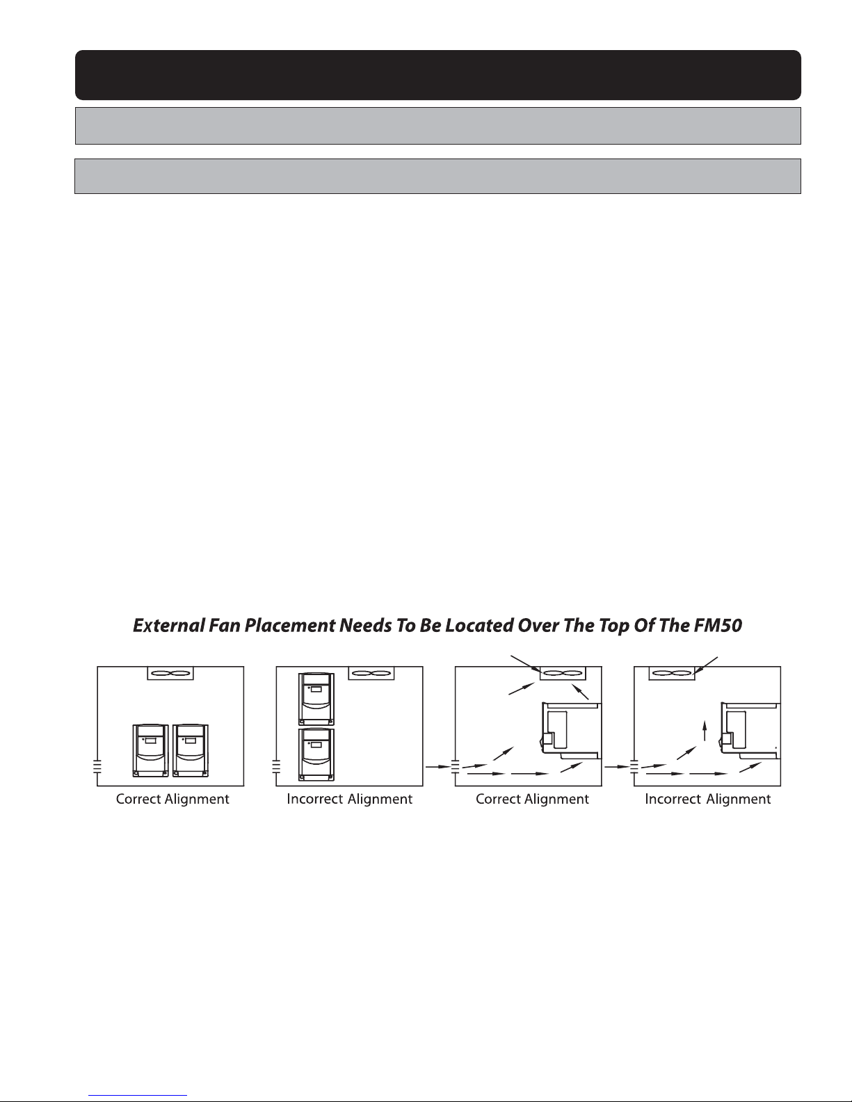
❙ If the FM50 is installed in an enclosed control panel, please remove the shield sticker located at the top of the AC drive.
This will allow additional airflow and cooling.
❙ For proper Installation of the FM50,you must place the front side of the AC Drive facing front and the top of the AC drive in
the up direction for better heat dissipation.
❙ Installation must be compliant to the following requirements.
Cooling Fan Cooling Fan Cooling Fan
Cooling Fan
Page 10
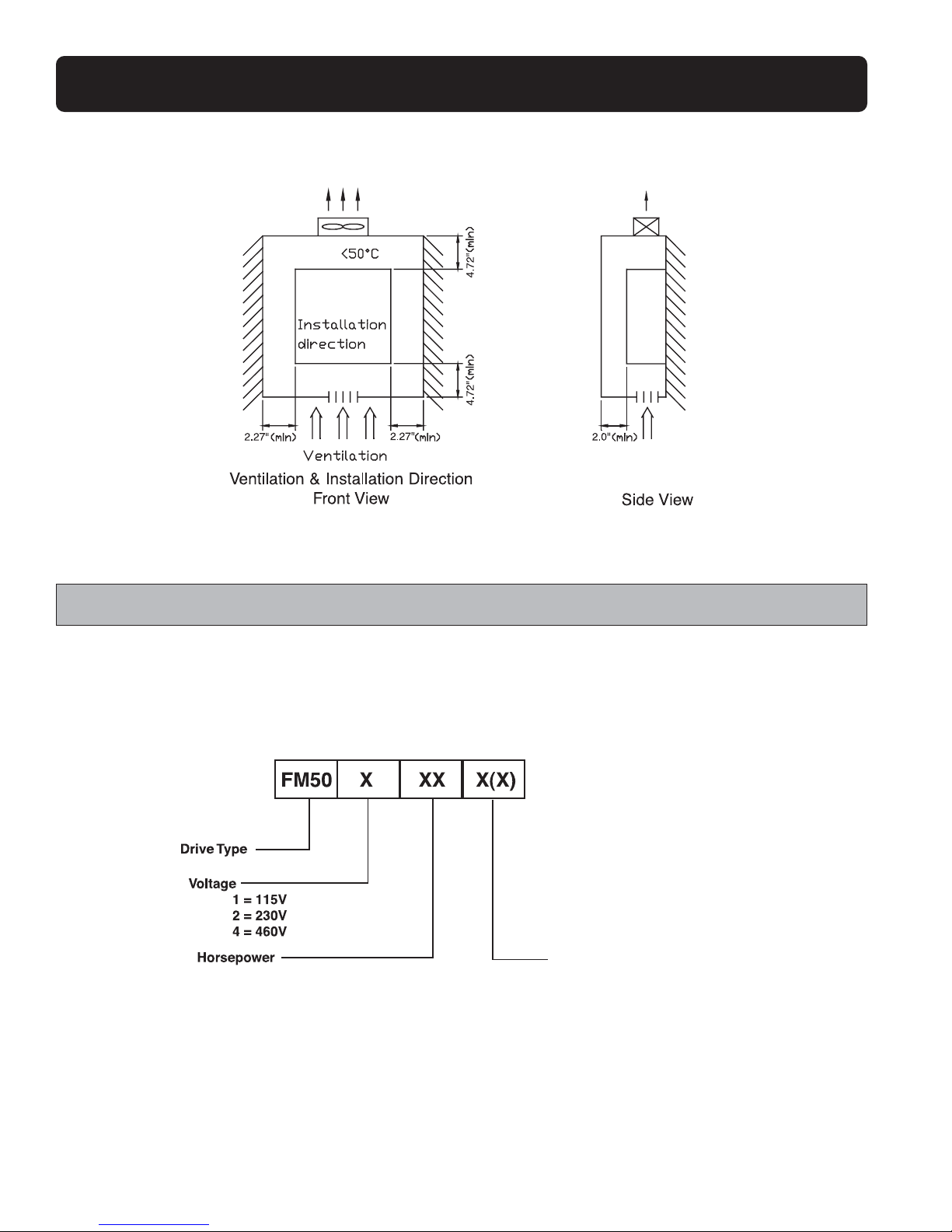
Note: Maximum temperature in the enclosure is 122˚F (50˚C) with Shield Sticker removed
2.2 Sample Model No. Identification
10
FLUXMASTER 50 INSTRUCTION MANUAL
C = Chassis
1
P2 = HP
/
4
03 = 3HP
N4 = NEMA 4
OC = Chassis with Filter
N4FS = NEMA 4 with Operator Devices
Page 11

2.3 SPECIFICATIONS
11
FLUXMASTER 50 INSTRUCTION MANUAL
2.3.1 Product Specifications
Model: FM50 1P2-X 1P5-X 101-X
Suitable Motor Power
0.2 0.4 0.75
Rating (KW)
Motor (HP) 1/4 1/2 1
Rated
Output Current (A) 1.4 2.3 4.2
Capacity (KVA) 0.53 0.88 1.6
Weight (lb) 2 2 2
Input Voltage Max. Single Phase 100-120V (+10%, -15%), 50 / 60Hz (+/-5%)
Output Voltage Max. Three Phase 200-240V (Proportional to input voltage)
Dimension H*W*D (inches) 5.20 x 2.84 x 4.65
EMC Specification Without Filter
Model: FM50 2P2-X 2P5-X 201-X 202-X 203-X
Suitable Motor Power
Rating (KW)
0.2 0.4 0.75 1.5 2.2
Motor (HP)
1
/
4
1
/
2 12 3
Output Current (A) 1.4 2.3 4.2 7.5 10.5
RatedCapacity (KVA) 0.53 0.88 1.6 2.9 4.0
Weight (lb) 2 2 2 5 5
Input Voltage Max. Single/Three Phase 200-240V (+10%, -15%), 50 / 60Hz (+/-5%)
Output Voltage Max. Three Phase 200-240V (Proportional to input voltage)
Dimension H*W*D (inches) 5.20 x 2.84 x 4.65 5.63 x 4.65 x 4.65 x 6.77
EMC Specification Without Filter
Model: FM50 401-X 402-X 403-X
Suitable Motor Power
Rating (KW)
0.75 1.5 2.2
Motor (HP) 1 2 3
Output Current (A) 2.3 3.8 5.2
RatedCapacity (KVA) 1.7 2.9 4.0
Weight (lb) 4 4 4
Input Voltage Max. Three Phase 380-480V (+10%,-15%), 50 / 60Hz (+/-5%)
Output Voltage Max. Three Phase 380-480V (Proportional to input voltage)
Dimension H*W*D (inches) 5.63 x 4.63 x 6.77
EMC Specification Without Filter
Page 12

FLUXMASTER 50 INSTRUCTION MANUAL
2.3.2 Functional Specifications
12
Item Specification
Input Signal Type (SOURCE) input (External 24VDC Input is allowed) (PNP type)
Control Method Sinusoidal wave PWM control
Frequency Range 1 ~ 200Hz*
1
Resolution Setting
Digital: 0.1Hz (1 ~ 99.9Hz); 1Hz (100 ~ 200Hz)
Frequency Analog: .06Hz / 60Hz
Control Keypad Setting Directly setup by ▲ ▼ buttons.
External Signal Setting 0 ~ 10V, 4 ~ 20mA, 0 ~ 20mA
Other Function Frequency upper and lower limit
Carrier Frequency 4 - 16KHz*
2
Accel/Decel Time 0.1 ~ 999 Sec
V/F Pattern 6 Patterns
Tor que Control Adjustable Torque boost level (manual torque boost)
2 Programmable Inputs,to be used as multi-speed 1(SP.1) / multi-speed
Control
Multi-Function Input 2(SP.2) *1/ Jog / External emergency stop / External Base Block Command/
Characteristics
Reset Command
Multi-Function Output One output contact available as Fault / Running / At speed signals.
Braking Torque
1P2~101/2P2~201: Approximately 20%
202/203/401/402/403: 20% ~ 100%, built-in braking transistor
Built-In Functions
Decelerate or free run stop, Auto reset,DC braking frequency /
Voltage / Time can be setup by constants.
Display
Three digit 7 segment LED display frequency / functions constants /
fault record /CPU version.
Operating Temperature 14 ~ 104˚F (-10 ~ 40˚C); 14 ~ 122˚F ( -10 ~ 50˚C) without shield sticker
Humidity 0 ~ 95% RH non-condensing.
Vibration Under 1G (9.8m/S
2
)
EMC Specification EN50081-1, EN50081-2, EN50178,EN61800-3 + All
UL UL508C
Overload Protection 150% for 1 minute
Overvoltage DC Bus voltage > 410V(100/200 series);DC Bus voltage > 800V(400 series)
Undervoltage DC Bus voltage < 200V(100/200 series); DC Bus voltage < 400V(400 series)
Protection Momentary
Power-loss 0 ~ 2 sec: AC drive can be restarted with Speed Search.
Function Power Loss
Stall Prevention During Acceleration / Deceleration/ Constant speed
Output Short-circuit Electronic circuit protection
Ground Fault Electronic circuit protection
Other Protection Heatsink overheat protection, Current limit
Installation Direct installation or DIN rail (Option).
Note: *1: CPU version v1.9 and above.
*2: Carrier Frequency Range: CPU Version v1.6 is 4 ~ 8kHz.
CPU Version v1.9 and above are 4 ~ 16kHz.
Page 13

2.3.3 Options and Wiring Specifications
13
FLUXMASTER 50 INSTRUCTION MANUAL
Molded-Case Circuit Breaker / Magnetic Contactor
❙ Warranty does not apply to damage caused by the following situations:
(1) Damage to the AC drive caused by the lack of appropriate molded-case circuit breaker or when an oversized circuit
is installed between the power supply and the AC drive.
(2) Damage to the AC drive caused by the magnetic contactor,phase advancing capacitor,or surge-protector installed
between the AC drive and the motor.
Model Type 1P2/1P2/2P2/2P5 101/201/202 203 401/402/403
Molded-Case Circuit Breaker 15A 20A 30A 15A
Primary Circuit Terminal Wire Dimension Wire Dimension Wire Dimension Wire Dimension
(#14 AWG) (#14 AWG) (#12 AWG) (#12 AWG)
2.0mm
2
2.0mm
2
3.5mm
2
3.5mm
2
Terminal Screw Terminal Screw Terminal Screw Terminal Screw
M3 M3/M4 M4 M4
Signal Terminal (TM2)
Wire Dimension 0.75 mm
2
(#18 AWG),Terminal Screw
1~11
Recommended Wire Type
Use Copper Conductors Only. Size Field Wire Based on 167˚F (75˚C) Wire Only.
Wire Voltage Rating Must Be a Minimum of 300V.
❙ Please utilize three-phase squirrel-cage induction motor with appropriate capacity.
❙ If the AC drive is used to drive more than one motor, the total capacity must be smaller than the capacity of the AC drive.
Additional thermal overload relays must be installed in front of each motor.Set Fn_18 at 1.0 times of the rated value
specified on the motor nameplate at 50Hz, 1.1 times of the rated value specified on the motor nameplate at 60Hz.
❙ Do not install phase advancing capacitors,LC, or RC components between the AC drive and the motor.
T1
L1
T2
L2
T3
M3
Page 14

From the Power Source:
❙ Apply the power source at the correct rated voltage to prevent damage to the AC drive.
❙ A Power Disconnect or Circuit breaker must be installed between the AC power supply and the AC drive.
Molded-Case Circuit Breaker:
❙ Utilize an appropriate circuit breaker that is suitable for the rated voltage and current ratings of the AC drive,to switch
ON/OFF the power supply to the AC drive,and as additional protection for the AC drive.
❙ Do not operate the circuit breaker to switch ON or OFF the AC drive.The circuit breaker should be used only to supply input
power and should not be used for operational sequences.
Ground Fault Circuit Breaker:
❙ To ensure personnel safety,a ground fault circuit breaker should be added to prevent false operation caused by
leakage current.
Magnetic Contactor:
❙ The Magnetic Contactor is not required for standard operation.To utilize external control,automatic restart, or breaking
controller,the magnetic contactor must be added at the primary side.
❙ Do not operate the magnetic contact to switch ON or OFF the AC drive.
Power Quality Improvement AC Reactor:
❙ If a large capacity power source is applied (over 600KVA), an additional AC reactor may be added to improve the
power factor.
Inverter:
❙ Power supply input terminals L1 and L2 are not differentiated on phase sequence.They can be arbitrarily connected.
❙ Output terminal T1,T2, and T3 should be connected to the U,V, and W terminals of the motor respectively. If motor turns in
opposite direction of the inverter command,exchange two of the three wire connections to correct this problem.
❙ Output terminal T1,T2, and T3 should never be connected to power source.Otherwise, damage to the AC drive could result.
❙ Properly ground the grounding terminal in compliance to 200V class type three grounding. (The 400V class type has
special grounding.)
2.3.4 Application and Recommendations for
Installing Auxiliary Equipment
14
FLUXMASTER 50 INSTRUCTION MANUAL
Page 15

15
FLUXMASTER 50 INSTRUCTION MANUAL
External wiring should be carried out in accordance with the following requirement.Check and reassure the wiring is correct
after completion.
(Do not utilize the control circuitry buzzer to check the wiring).
EMI Connections:
It is very important that the connections between the AC drive,the shielded motor cable, and the EMI filters are tested as follows.
❙ Use a metal grounding plate and place the AC drive and the EMI filter on the plate.
❙ Use a shielded motor cable with 4 connectors (U,V,W, & Earth). Don't use the shielding as safety earth (shield is high
frequency earth).
❙ Remove any paint around the two metal coupling nut holes to ensure that the metal coupling nuts (and the shielding) make
contact with the AC drive and the motor.
❙ Don't solder a conductor to the shielding.
❙ Use a metal clamp to connect the shielding from the motor cable with the metal grounding plate.This ensures a perfect
high frequency earth connection between AC drive, grounding plate and EMI filter.
❙ Keep the distance between the AC drive and EMI filter as short as possible (< 11.8").If longer, use a shielded cable with a
metal coupling nut and a metal clamp to connect the shielded cable to the AC drive and metal grounding plate.
❙ The only earth connection between the LISN and the test plate should be via the EMI filter.
❙ Use a motor rated at or below the AC drive rating.
❙ Install a noise filter for AC drive on the output side of the primary circuit to suppress conducting noise.
Filter (Optional)
Page 16
❙ When the distance between the AC drive and motor is longer than 330ft (100m) cable wire should be carefully chosen
to reduce the wiring resistance below 3% and the voltage drop (V ) = 3 x Wire resistance (52/ft) x wire length (ft) x current.
❙ Control circuitry wiring must be separately terminated and away from the primary power circuitry and other high-voltage or
large-current power lines to avoid noise interference.
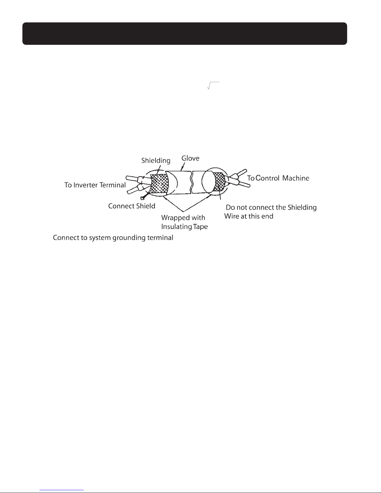
❙ To r educe the noise interference and avoid possible operational problems,shielded twisted pair cable should be used
to wire the control circuitry.Please refer to following diagram. Connect the shield wire to the grounding terminal.
Connect only one end of the shield.
❙ Wiring distance of 164ft (50m) or under is recommended.
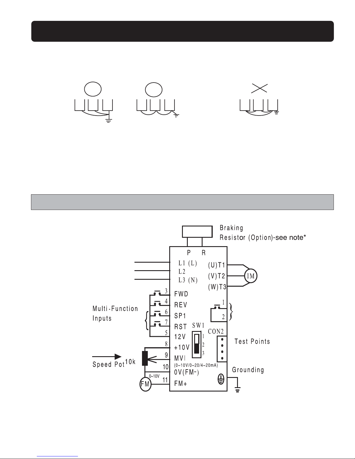
❙ The grounding terminal of the AC Drive must be correctly grounded in compliance with 200V class type three grounding.
❙ Grounding wire should be wired in accordance to electrical equipment (AWG) with the length of the grounding wire as
short as possible.
❙ The grounding wire of the AC drive must not be grounded together with other large current loads (such as soldering
machines or large current motors).They should be grounded separately.
16
FLUXMASTER 50 INSTRUCTION MANUAL
Page 17
17
FLUXMASTER 50 INSTRUCTION MANUAL
❙ Ground circuit must not be formed when grounding several AC drives together.
(D) Wire specification.Apply appropriate wire with correct diameter for primary power circuitry and control circuitry in
compliance with NEC or other applicable codes.
2.4 Wiring Diagram
Wire Terminations to the AC drive must be made with either UL listed field wiring lugs or UL listed crimp type ring terminals.
*Note: Only for 230V 2,3HP and 460V 1-3HP models.
(a) correct
(b) correct
(c) incorrect
3ø
?
Multi-Function Output
Page 18
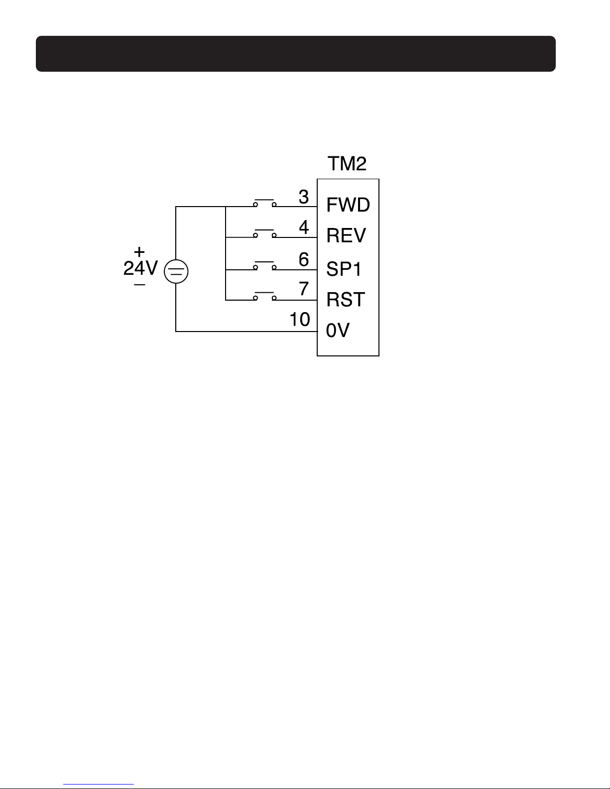
External 24V Supply
18
FLUXMASTER 50 INSTRUCTION MANUAL
Page 19
19
FLUXMASTER 50 INSTRUCTION MANUAL
Inverter Terminal Descriptions, Primary Circuitry Terminal Block (TM1) Description
Te rminal Symbol Function Description
L1/L (R) Primary power source input to Drive
L2 (S) Single phase: L1/L2 or L/N
L3/N (T) Three phase: L1/L2/L3
PExternal braking resistor terminal
R (230V, 2/3HP and 460V,1-3HP models only)
T1 (U)
T2 (V) Inverter output to Motor
T3 (W)
Tightening torque for TM1 is 1lb-ft or 12lbs-in (all 115VAC models and 230V 1/4 - 1HP)
Tightening torque for TM1 is 1.3lbs-ft or 16lbs-in (230V 2, 3HP and 460V 1-3HP)
* Wire voltage rating must be a minimum of 300V(200V series)/600V(400V series)
Control Circuitry Terminal Block (TM2) Description
Te rminal Symbol Function Description
1 TRIP Fault relay output terminal (Multi-Function output terminal) (see parameter F_21)
2 RELAY Connection point rated capacity 250VAC/1A (30VDC/1A)
3 FWD (FW)
Operation control terminals (see parameter F_03)
4REV (RE)
5+ 12V(12) Common point for terminals 3 / 4 / 6 / 7
6 SP1(SP)
Multi-Function input terminals (see parameter F_19)
7 RESET(RS)
8 +10V Power terminal for potentiometer (Pin 3)
Analog input wire
Analog frequency signal input terminal (Pin 2 of
9potentiometer or positive terminal of 0~10V /
4~20mA / 0~20mA)
Wiper
10
0V(FM -)
Analog common
Analog signal common point (Pin 1 of potentiometer)
or negative terminal of 0~10V / 4~20mA / 0~20mA)
11 FM+
Analog output positive Analog frequency signal output terminal
connection point Output terminal signal is 0 ~ 10VDC/Fn_6
Tightening torque for TM2 is 0.42lb-ft or 5.03lbs-in.
* Wire voltage rating must be a minimum of 300V.
* Control wiring should not run in the same conduit or raceway with any power or motor wiring.
* Single Input and Output Terminals (TM2) Ratings are ALL Class 2.
* Use copper conductors only. Size field wiring based on 167˚F (75˚C) wire only.
Page 20
20
FLUXMASTER 50 INSTRUCTION MANUAL
SW1 Function Description
Switch 1 External Signal Type
0 ~ 20mA analog signal (When F_11 is set to 1)
4 ~ 20mA analog signal (When F_11 is set to 2)
0 ~ 10VDC analog signal (When F_11 is set to 1)
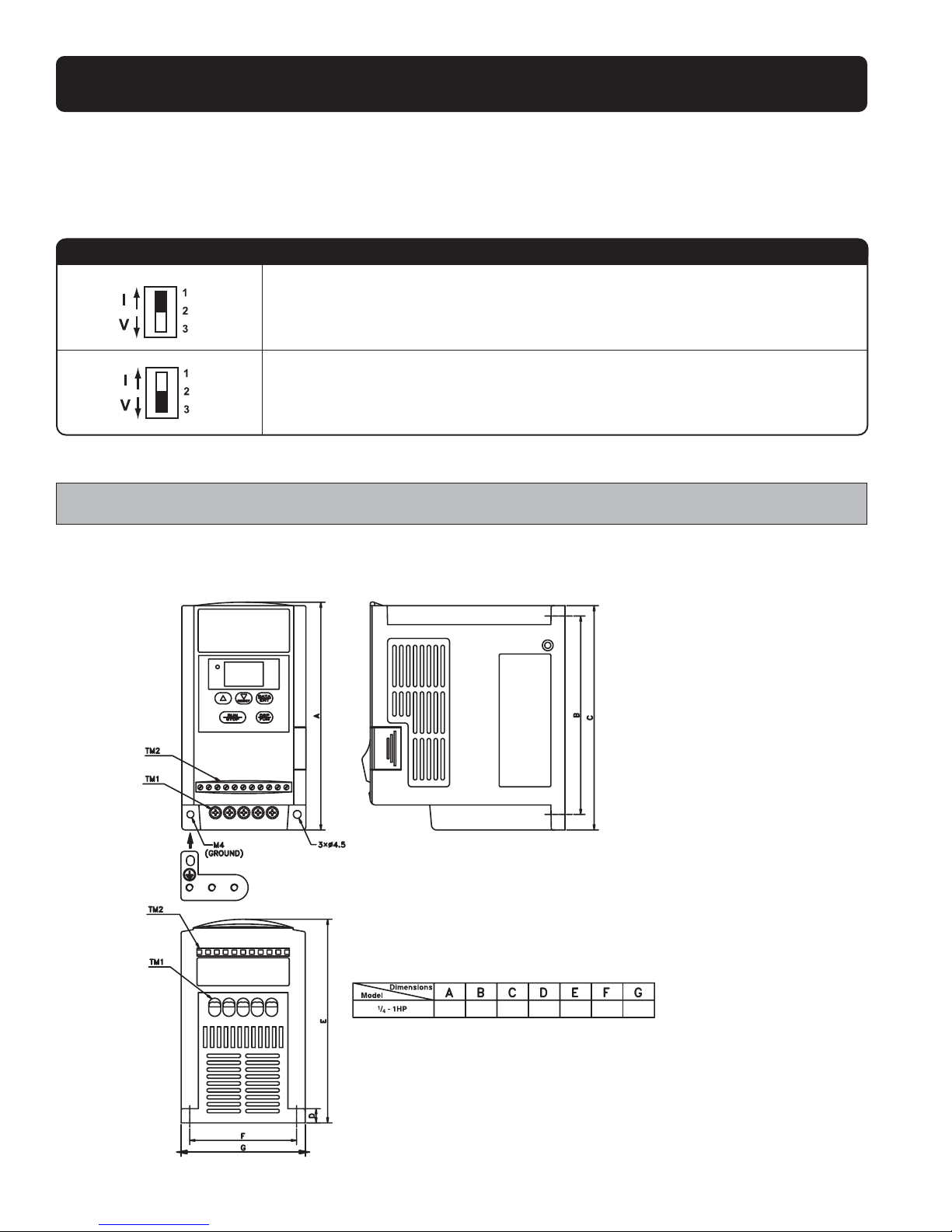
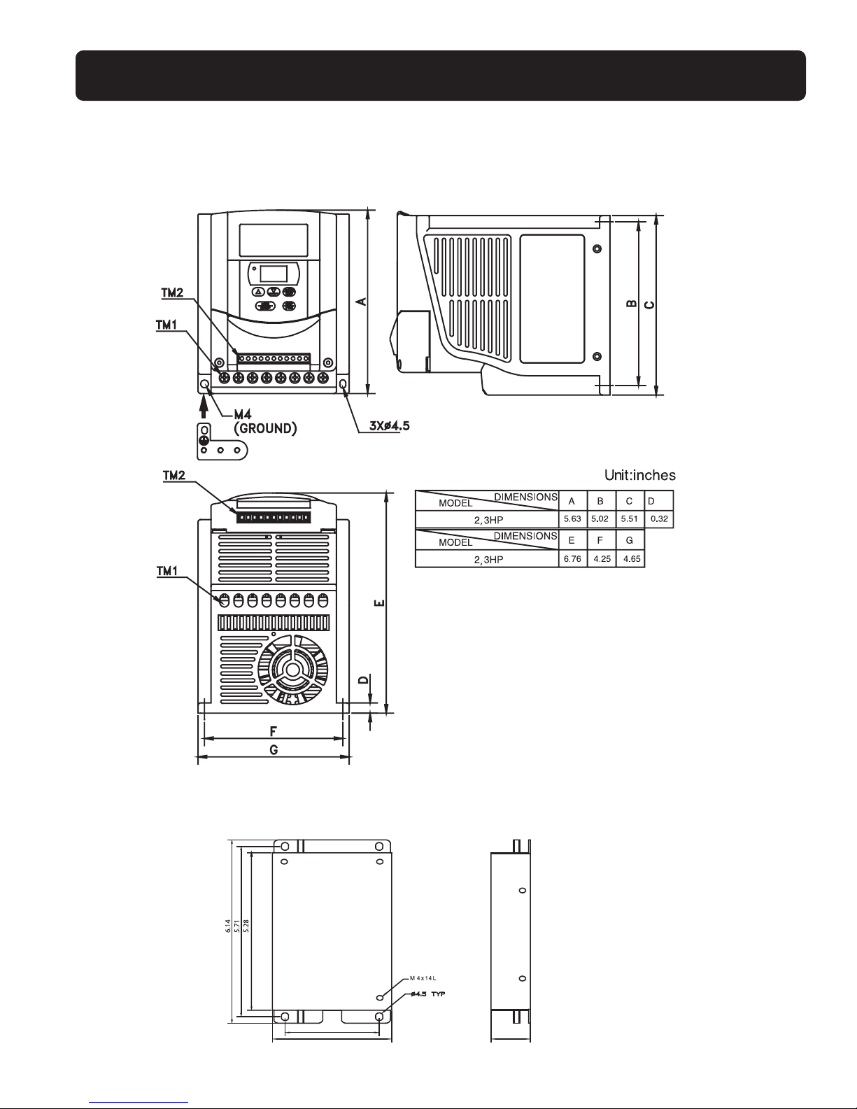
2.5 Dimensions & Location of Terminal Block
115V 1/4 - 1HP, 230V 1/4 - 1HP models
NOTE:For safety reasons,we strongly recommend removing the M4 grounding
screw,then attach the enclosed "metal frame grounding terminal" on the same
location to make a grounding bar to ensure proper grounding.
Unit: inches
5.20 4.57 5.12 0.32 4.65 2.40 2.83
Page 21
21
FLUXMASTER 50 INSTRUCTION MANUAL
230V, 2, 3HP, 460V 1 - 3HP
Dimensions & Installation of Class B Filter
2.36
2.99
0.98
Page 22

DIMENSIONS
FM50 NEMA 4X (IP65 Indoor Duty) with operators (115V, 230V 1/4 - 1HP models)
22
FLUXMASTER 50 INSTRUCTION MANUAL
Page 23

23
FLUXMASTER 50 INSTRUCTION MANUAL
INSTALLATION
FM50 NEMA 4X (IP65 Indoor Duty) with operators (115V, 230V, 1/4 -1HP models)
NOTE :
1. Power switch, REV-0-FWD switch and potentiometer are only available for NEMA 4X units with operator devices
2. Power supply cable: #14 AWG (2.0mm2)
3. Motor cable: #16 AWG (1.25mm2)
4. Tightening torque values for terminals
(1). Power/Motor cable (plug-in) terminal:4.34in-lb (5kg-cm)
(2). Remote control wire:3.47in-lb (4kg-cm)
Potentiometer
DATA
RESET
ENT
RUN
DSP
STOP
FUN
L1 L2
50 /6 0 H z
Sin g le P h a se
T1 T2 T3
3 Phase
IM
REV-0-FWD
SW ITCH
POW ER
SWITCH
7.83" (198.80mm)
4.86" (123.40mm)
Page 24

CONNECTION
Circuit Diagram
FM50 NEMA 4X (IP65 Indoor Duty) with operators (115V, 230V, 1/4 - 1HP models)
NOTE :
1. Power switch, REV-0-FWD switch and potentiometer are only for NEMA 4X units with operator devices.
2. Power supply cable: #14 AWG (2.0mm2)
3. Motor cable: #16 AWG (1.25mm2)
4. Tightening torque value for terminals:
(1). Power/Motor cable (plug-in) terminal:4.34in-lb (5kg-cm)
(2). Remote control wire:3.47in-lb (4kg-cm)
(3). Outer cover (M4):5.20in-lb (6kg-cm)
5. Input source: single-phase (L1,L2, ), make sure that it is connected to the appropriate power supply.
6. Output motor: three-phase ( ,T1,T2, T3)
CAUTION
-Do not start or stop the AC drive using the main circuit power.
- NEMA 4X with operators:Always maintain REV-0-FWD switch at 0 position. This will ensure that the AC drive is stopped
before power up after power supply interruption.Otherwise, injury may result to personnel.
24
FLUXMASTER 50 INSTRUCTION MANUAL
Page 25

25
FLUXMASTER 50 INSTRUCTION MANUAL
CONNECTION
FM50 NEMA 4X (IP65 Indoor Duty) (115V,230V,1/4 - 1HP models)
MOUNTING
Page 26

CONNECTION
FM50 NEMA 4X (IP65 Indoor Duty) with operators (115V, 230V, 1/4 - 1HP models)
MOUNTING
26
FLUXMASTER 50 INSTRUCTION MANUAL
Page 27

27
FLUXMASTER 50 INSTRUCTION MANUAL
DIMENSIONS
FM50 NEMA 4X (IP65 Indoor Duty) with operators (230V 2, 3HP, 460V 1 - 3HP models)
Page 28

INSTALLATION
FM50 NEMA 4X (IP65 Indoor Duty) with operators (230V 2, 3HP, 460V 1 - 3HP models)
NOTE :
1. Power switch,REV-0-FWD switch and potentiometer are only for NEMA 4X units with operator devices.
2. Power supply cable:230V #12 AWG (3.5mm2); 460V #16 AWG (1.25mm2)
3. Motor cable: 230V #14 AWG (2.0mm
2
); 460V #16 AWG (1.25mm2)
4.Tightening torque values for terminals:
(1). Power/Motor cable (TM1,TM3) Terminal:6.94in-lb (8kg-cm)
(2). Remote control wire:3.47in-lb (4kg-cm)
(3). Outer cover (M4):6.94in-lb (8kg-cm)
*Models FM50-202-N4FS & FM50-203-N4FS with operator devices are single phase input only.
28
FLUXMASTER 50 INSTRUCTION MANUAL
Page 29

29
FLUXMASTER 50 INSTRUCTION MANUAL
CONNECTION
Circuit Diagram
NEMA 4X (IP65 Indoor Duty) with operators (230V 2, 3HP, 460V 1 -3HP models)
NOTE :
1. Power switch,REV-0-FWD switch and potentiometer are only for NEMA 4X units with operator devices
2. Power supply cable:#12 AWG (3.5mm
2
)
3. Motor cable: #16 AWG (1.25mm2)
4.Tightening torque values for terminals:
(1). Power/Motor cable (plug-in) terminal:4.34in-lb (5kg-cm)
(2). Remote control wire:3.47in-lb (4kg-cm)
(3). Outer cover (M4):5.20in-lb (6kg-cm)
5. Input source: single-phase or three-phase (L1, L2, L3, ) ensuring that it is connected to a 200/230V or a 400/460V supply.
(Models FM50-202-N4FS & FM50-203-N4FS with operator devices are single phase input only).
6. Output motor: three-phase ( T1, T2,T3)
CAUTION
-Do not start or stop the AC drive using the main circuit power.
- NEMA 4X with operators:Always maintain REV-0-FWD switch at 0 position. This will ensure that the AC drive is stopped
before power-up again after power supply interruption.Otherwise, injury may result to personnel.
Page 30

CONNECTION
FM50 NEMA 4X (IP65 Indoor Duty) (230V 2,3HP, 460V 1 -3HP models)
MOUNTING
NOTE:
For ALL MODELS WITH FILTERS,additional items will be found inside the box including: QTY 1 of EMC waterproof conformed
(IP65) ferrite core;QTY 1 of metal fastener; QTY 1 of MF Zin 5-C screw.
CAUTION
If the EMC regulation must be met, constrain the motor cables with the ferrite core onto the motor cable outside the plastic
enclosure as indicated in the above diagram.
Please Note: The length of the motor cable CANNOT exceed 5M under EMC regulation.
30
FLUXMASTER 50 INSTRUCTION MANUAL
Page 31

31
FLUXMASTER 50 INSTRUCTION MANUAL
CONNECTION
FM50 NEMA 4X (IP65 Indoor Duty) with operators (230V 2,3HP, 460V 1 -3HP models)
Page 32

EMC MOUNTING
NEMA 4X (IP65 Indoor Duty) with operators ((230V 2,3HP, 460V 1 -3HP models)
32
FLUXMASTER 50 INSTRUCTION MANUAL
Page 33

33
FLUXMASTER 50 INSTRUCTION MANUAL
2.6 Mounting Instructions
Page 34

Din Rail Mounting Diagram
DIN Rail Installation
A mounting clamp and a 1.38”width rail must be used to install the drive on the rail.
34
FLUXMASTER 50 INSTRUCTION MANUAL
Step 1 -
Aim and insert the 4
retention ribs of the DIN
rail at the 4 holes in rear
panel of AC drive
Step 2 -
Push the DIN rail
forward until the middle
rib grips firmly with
back panel
Step1-
Use a small screwdriver,
inserting it into the
middle rib of DIN rail
and press the screwdriver
in order to remove the
DIN rail from the AC drive
1. Pull the mounting plate downward.
2. Rotate the inverter module to dismount it.
First place the groove on the back of module on
the upper edge of din rail, then push the module
down to lock-up position.Finally press the mounting plate upward into module.
Page 35

3. Software Index
35
FLUXMASTER 50 INSTRUCTION MANUAL
3.1 Keypad Operating Instructions
Keypad Description
CAUTION
To avoid damage, do not operate keypad by screwdriver or other sharp-ended tool.
Keypad Operation Flowchart
Note 1: Displays setting of frequency when stopped.Displays output frequency when running.
Note 2: The setting of the frequency can be modified either when stopped or when running.
Page 36

3.2 Parameter List
36
FLUXMASTER 50 INSTRUCTION MANUAL
Function F_ Function Description Unit Range
Fac tory
Page Note
Setting
Factory Setting 0 Factory Adjustment
Accel.Time 1 Accel.Time 0.1Sec 0.1 ~ 999S 5.0 37 *1 *3
Decel.Time 2 Decel.Time 0.1Sec 0.1 ~ 999S 5.0 37 *1 *3
Operation Mode
3
0: Forward / Stop,Reverse / Stop
1: Run/Stop,Forward / Reverse
10
~
1038
Motor Rotation
4
0: Forward
Direction: 1: Reverse
10 ~ 1038*1
V/F Pattern 5 V/F pattern setting 1 1 ~ 6 1/4 39 *2
Frequency 6 Frequency upper limit 0.1Hz 1 ~ 200 50/60Hz 40 *2 *3
Upper/Lower Limit 7 Frequency lower limit 0.1Hz 1 ~ 200 0.0Hz 40 *3
SP1 Frequency 8 SP1 frequency 0.1Hz 1 ~ 200 10Hz 40 *3
JOG Frequency 9 JOG frequency 0.1Hz 1 ~ 200 6Hz 40
Start / Stop Control 10
0: Keypad
10 ~ 1041
1:Terminal (TM2)
0: Keypad
Frequency Control 11 1:Terminal (0~10V / 0~20mA) 1 0 ~ 2 0 41
2:Terminal (4~20mA)
Carrier frequency
12 Carrier Frequency Setting 1
1 ~ 5
542*4
Control (1~10)*4
Tor que Compensation 13 Torque compensation gain 0.1% 0.0 ~ 10.0% 0.0% 42 *1
Stop Method 14
0: Controlled deceleration stop
10 ~ 1043
1: Coast to stop
15 DC braking time 0.1S 0.0 ~ 25.5S 0.5S 43
DC Braking Setting 16 DC braking injection frequency 0.1Hz 1 ~ 10Hz 1.5Hz 43
17 DC braking level 0.1% 0.0 ~ 20.0% 8.0% 43
Electronic Thermal
18
Protection based on motor rated
50 ~ 100%
Overload Protection
current
1%
(0~200)
100% 44 *4
Multi-Function input terminal 1
1: Jog
19
(SP1) function
2: SP1 2 33
Multi-Function Input 3: Emergency Stop
Connection Point
Multi-Function input terminal 2
4: External Base Block
20
(RESET) function
5: Reset 5 45
6: SP2*4
1: Operating
Multi-Function Output 21 Multi-Function output terminal 2: Frequency Agreed 3 46
3: Fault
Page 37

FLUXMASTER 50 INSTRUCTION MANUAL
37
Function F_ Function Description Unit Range
Fac tory
Note Page
Setting
Reverse Lock-Out 22
0: REV run
10
~
1046
1: REV run Lock-Out
Momentary Power
23
0: Enabled
Loss 1: Disabled
10 ~ 1046
Auto Restart 24 Number of Auto-restart times 1 0 ~ 5 0 47
Restore factory settings 25
010: Constants initialization to 50Hz system
47 *2
020: Constants initialization to 60Hz system
SP2 Frequency 26 SP2 frequency 0.1Hz 1.0 ~ 200Hz 20 48 *4
SP3 Frequency 27 SP3 frequency 0.1Hz 1.0 ~ 200Hz 30 48 *4
Power Up Start 28
0: Enable
10 ~ 1148*4
1: Disable
Software Version 29 CPU program version 48
Fault Log 30 Fault log for three faults. 48
NOTE:
*1 : Parameters that can be adjusted while running the drive.
*2 : Please refer to parameters F_25.
*3 : If the setting range is above 100, the setting unit becomes 1.
*4 : New features for CPU versions V2.1 and above.
3.3 Parameter Function Description
F_00 Factory Adjustment Parameter. Do not change.
F_01 : Acceleration Time = 0.1 ~ 999 sec
F_02 : Deceleration Time = 0.1 ~ 999 sec
1. Acceleration / Deceleration time calculation formula:
Acceleration time = F_01 x Frequency Setting
60Hz
Deceleration time = F_02 x Frequency Setting
60Hz
Page 38

38
FLUXMASTER 50 INSTRUCTION MANUAL
F_03: Operation Mode Selection = 0: Forward / Stop, Reverse / Stop
1: Run / Stop, Forward / Reverse
NOTE 1: F_03 takes effect only when F_10 = 1 (external operation control)
Note: Reverse command is ignored when F_22 = 1 (Reverse lockout)
F_04: Motor Rotation Direction Setting = 0: Forward
1: Reverse
Although there is no Forward / Reverse pushbutton on the digital control panel,it is possible to adjust forward / reverse function
by changing the F_04 setting.
NOTE: When F_22 = 1:Reverse is disabled. F_04 cannot be set to 1.
The keypad indication will display "LOC".
NOTE: F_04 takes effect only when F_10 = 0 (Keypad start/stop control mode)
Page 39

39
FLUXMASTER 50 INSTRUCTION MANUAL
F_05: V/F Pattern Setting = 1 ~ 6
Select F_05 = 1 - 6 to select one of the six preset V/F patterns (refer to the following tables).
Specification 50Hz System
Application General Application High Starting Torque Decreasing Torque
F_5 1 2 3
50Hz System
V/F pattern
Specification 60Hz System
Application General Application High Starting Torque Decreasing Torque
F_5 4 5 6
60Hz system
V/F pattern
F_5 B C
1/4 10% 8%
2/5 15% 10.5%
3/6 25% 7.7%
Page 40

F_06: Frequency Upper Limit Range = 1 ~ 200Hz
F_07: Frequency Lower Limit Range = 1 ~ 200Hz
F_06: Factory setting refer to F_25.
NOTE:
If F_07 = 0Hz, the frequency instruction is equal to 0Hz;the AC drive will stop at 0 speed.
If F_07 > 0Hz, the AC drive will output a minimum speed according to the setting in F_07.
F_08: SP1 Frequency = 1 ~ 200Hz
F_09: JOG Frequency = 1 ~ 200Hz
1. When F_19 or F_20 = 2 (multi-function input setting) and the multi-function input terminal is ON, the inverter operates at
SP1 frequency (F_08).
2. When F_19 or F_20 = 1 (multi-function input setting) and the multi-function input terminal is ON, the inverter operates at JOG
frequency (F_09).
3. When multi-function input terminals 1 and 2 are configured for SP1 frequency and JOG frequency, the priority of the
frequency setting is: JOG,SP1, Keypad setting, external frequency signal using a speed pot.
40
FLUXMASTER 50 INSTRUCTION MANUAL
Frequency Setting Signal
Internal
Frequency
Signal
(Note)
F_06 (Freq.Upper Limit)
F_07 (Freq.Lower Limit)
Page 41

41
FLUXMASTER 50 INSTRUCTION MANUAL
F_10: Start / Stop Control = 0 : Keypad
=1:Terminal (TM2)
NOTE:When F_10 = 1 (Terminal Control),emergency stop on the Keypad is enabled.
To avoid injuries to personnel or equipment damage when F_10 = 1, please refer to the descriptions of F_23/24 (Momentary
power loss ride-through and number of auto restart attempts).
Priority of selections for JOG, multi-function, and keypad/external frequencies
F_11: Frequency Control = 0 : Keypad
=1:Analog Speed Pot Terminal (TM2) (0 ~ 10V / 0-20mA)
=2:Analog Speed Pot Terminal (TM2) (4-20mA)
NOTE 1:
If the jog when start/stop control is set to keypad run
or SP1 frequency is switched on, the frequency is set
by SP1 speed and the frequency set up via the ▼▲ buttons
on the keypad are disabled.Original settings will be restored
after the SP1 connection or jog input is removed.
NOTE 2:
During the contact closure of the jog function, the keypad
control remains inactive until the jog contact connection
is reopened.
F_06
0mA 4mA 20mA
0V 10V
Fn_11=1
Fn_11=2
Page 42

F_12: Carrier Frequency = 1 ~ 10
F_12 Carrier Frequency F_12 Carrier Frequency F_12 Carrier Frequency
14 kHz 5 8 kHz 9 15 kHz*1
2 5 kHz 6 10 kHz*1 10 16 kHz*1
36 kHz 7 12 kHz*1
4 7.2 KHz 8 14.4 kHz*1
NOTE:
*1: Available for CPU version V1.9 and above.
2: If F_12 = 7~10, the inverter must operate with light loads.
Although an IGBT TYPE AC drive can provide a low audible noise level during its operation, it is possible that the switching of the
high carrier frequency may interfere with external electronic components (or other controllers) or even cause vibration in the
motor.Adjusting the carrier frequency can usually correct this problem.
F_13: Torque Compensation Gain = 0 ~ 10%
To enhance AC drive output torque patterns according to the B, C voltage points on the V/F pattern (refer to F_05 description)
and the (F_13) for this feature.
NOTE: When F_13 = 0,the torque boost function is disabled.
42
FLUXMASTER 50 INSTRUCTION MANUAL
Voltage
Hz
F_13=
B
C
100%
1 2.5/3.0 50/60
Page 43

43
FLUXMASTER 50 INSTRUCTION MANUAL
F_14 Stopping Method = 0 : Controlled deceleration stop
= 1 : Coast to stop
F_15 DC Braking Time = 0 ~ 25.5 sec
F_16 DC Braking Starting Frequency = 1 ~ 10Hz
F_17 DC Braking Level = 0 ~ 20%
If F_14 = 0
When the AC drive receives the stop command, it decelerates to the preset frequency set by F_16.After this, the output voltage
level that is set in F_17 will determine the amount of DC voltage that is injected into the motor. The time duration to perform this
stopping function is set in F_15.
If F_14 = 1
The inverter stops output immediately after receiving the stop command.The motor will enter into a coast to stop state until it
comes to a complete stop.
F_18: Motor Rated Current = 50 ~ 200%
1.The electronic thermal overload protection for the motor is as follows:
(1) Motor rated current = AC drive rated current x F_18.(F_18 = Motor rated current / AC drive rated current)
(2) When the load is within 100% of the motor’s rated current,the operation continues. When the load reaches 150% of the
motor’s rated current, the operation is allowed to continue for 1 minute.(Refer to curve (1) in Figure 3)
(3) After protecting the motor with the electronic thermal switch activated, the AC drive is cut off immediately.The OL1 light
will flash.To resume operation,push the RESET button or activate an external reset contact wired to Terminal 2.
(4) When the motor is operating at low speeds, the heat dissipation efficiency is lower. The electronic thermal activation level is
also reduced.(to change from curve (1) to curve (2) in Figure 3. Choose the appropriate F_05 setting according to the applied
motor to reach the desired performance.
Page 44

2.The electronic thermal protection for the AC Drive is as follows:
(1) When the load is within 103% of the AC drive rated current,the operation continues. When the load reaches 150% of rated
current of the AC drive,the operation will continue for 1 minute.(Refer to curve (1) of figure 3)
(2) After the activation of the electronic thermal switch, the AC drive is shut off immediately. (The OL2 light will flash) To resume
the operation, push RESET button or activate an external reset contact wired to Terminal 2.
F_19: Multi-Function Input Terminal 1 = 1~ 5 (1 ~ 6: CPU version v1.9 and above)
F_20: Multi-Function Input Terminal 2 = 1~ 5 (1 ~ 6: CPU version v1.9 and above)
1. F_19 = 1 or F_20 = 1: JOG control (refer to F_09;Jog Frequency Setting):
2. F_19, F_20 = 2 or 6 Multi-speed control (refer to F_08, F_26,F_27; Multi-speeds 1-3 settings):
F_19 = 2 & F_20 = 6:
TM2 SP1 Terminal TM2 SP1 Terminal Output Frequency
ON OFF F_08
OFF ON F_26
ON ON F_27
F_19=6 & F_20=2:
TM2 SP1 Terminal TM2 SP1 Terminal Output Frequency
ON OFF F_26
OFF ON F_08
ON ON F_27
44
FLUXMASTER 50 INSTRUCTION MANUAL
Page 45

45
FLUXMASTER 50 INSTRUCTION MANUAL
3. F_19,F_20 = 3: External Emergency Stop
When the external emergency stop signal is activated,the AC drive proceeds to decelerate and stop,(ignoring the stopping
method setting of F_14).The AC drive E.S. light will flash after stopping.After the emergency stop signal is deactivated, turn the
RUN switch OFF and then ON again to cycle it in the terminal mode.(F_10 = 1) Or press the RUN key in the keypad mode (F_10 =
0).The AC drive will then resume operation and restart. If the emergency stop signal is removed before the AC drive stops, the AC
drive will still execute the emergency stop.
4. F_19,F_20 = 4: External Base Block (Immediate Shut Down)
When the external base block signal is activated,the AC drive output will be immediately shut off (ignoring the stopping
method setting of F_14) and flash b.b.Light. After the base block signal is deactivated,turn the RUN switch OFF and then ON
again (F_10 = 1) or press the RUN key (F_10 = 0), the inverter will restart from the original starting frequency.
5. F_19,F_20 = 5: Auto Reset when AC drive faults.
F_21: Multi-Function Output Terminal Control = 1 ~ 3
1. F_21 = 1: Run mode signal
2. F_21 = 2: At Frequency Speed Signal
3. F_21 = 3: Fault signal
Terminals 1 and 2 of TM2 are activated for the following faults:CPF,OL1, OL2,OCS, OCA,OCC, Ocd ,Ocb ,OVC , LVC , OHC.
Refer to Section 4 for information on faults.
External Emergency Stop
External Base Block
Page 46

F_22: Reverse Lockout = 0: REV run command enabled
= 1: REV run command Lockout
NOTE:
When F_04 (motor rotation direction) is set to 1 (reverse),F_22 cannot be set to 1. In order to properly lockout a motor direction,
F_04 must be set at 0 before setting F_22 to 1.
F_23: Auto-restart after Momentary Power Loss = 0: Auto-restart enabled
= 1: Auto-restart disabled
1. When the AC power supply is temporarily below low voltage protection levels due to low line supply or unusually large
demands on the power supply system,the AC drive will stop immediately. If the voltage level recovers within 2 seconds,
the AC drive can restart by using its speed search program.
2. When F_23 = 0:
(1) If the momentary power loss is less than 2 seconds,the AC drive resumes operation automatically via speed search at 0.5
seconds after power up.The number of auto restart times is not limited by F_24.
(2) If the momentary power loss is long,the operation of the AC drive is based on the setting of F_10 and the condition of the
external switch.
(3) If the time of momentary loss is between the above two conditions,whether the AC drive will auto-restart depends
on F_24:
F_24 = 0: Auto-restart disabled.
F_24 = 1 ~ 5: Auto-restart enabled 1~5 times.
46
FLUXMASTER 50 INSTRUCTION MANUAL
Page 47

47
FLUXMASTER 50 INSTRUCTION MANUAL
3. When F_23 = 1,
(1) Power up after momentary power loss, the AC drive will not start. Even if F_24 > 0.
(2) If the momentary power loss is long, the AC drive must be restarted manually.The operation of the AC drive is based on
the setup of F_10 and the condition of external switch.
4. When restarting the AC drive, the operation of the AC drive is based on the setup of F_10 (start/stop control) and the
condition of external switches (FWD/REV button).
(1) When F_10 = 0, the AC drive will not restart.
(2) When F_10 = 1 and the external switch (FWD/REV button) is OFF, the AC drive will not restart.
(3) When F_10 = 1 and the external switch (FWD/REV button) is ON, the AC drive will automatically restart.
Attention: Based on safety issues, please turn off the external switch (FWD/REV button) after power loss to avoid possible
damage to personnel and the machine after sudden regeneration of power.
F_24: Number of Auto-Restart Times = 0 ~ 5
1. When F_24 = 0, the AC drive will not auto-restart after a fault recovery. (Except for momentary power
loss,please refer to F_23 for details)
2. When F_24 = 1~5: the AC drive will resume operation via speed search at 0.5 seconds under auto-restart after fault recovery.
(Except for momentary power loss,please refer to F_23 for details).
3. When the AC drive is set to deceleration or DC braking, the transient restart procedure is not performed.
4. If either of following situations should develop, the auto restart times will be reset:
(1) No additional faults (in operation or stop) occurs within 10 minutes.
(2) Press RESET button.
F_25: Restore to Factory Settings
= 010: Constants initialization to 50Hz system
= 020: Constants initialization to 60Hz system
1. When F_25 is set to 010, all parameters are restored to factory settings.The settings of F_05 = 1 and F_06 = 50. F_25 is restored
back to 000 after the reset process is complete.(50Hz operation)
2. When F_25 is set to 020, all parameters are restored to factory settings.The settings of F_05 = 4 and F_06 = 60. F_25 is restored
back to 000 after the reset process is complete.(60Hz operation)
Page 48

F_26: SP2 (1 ~ 200Hz) ,Multi-speed 2 (Refer to F_19 / F_20)
F_27: SP3 (1 ~ 200Hz) ,Multi-speed 3 (Refer to F_19 / F_20)
F_28: Power Up Start = 0 : Power Up start enabled when remote Run command on
= 1 : Power Up start disabled when remote Run command on
(CPU version V2.1 and above)
When F_28 = 1 and control mode is remote control (F_10 = 1),the AC drive can not start if the RUN switch is ON when power is
engaged.The run signal must be toggled off then on to run the AC drive.
F_29: CPU Program Version
F_30: Fault log for last three faults
1. Last three faults: indicate the sequence of the occurrence of faults by the location of decimal point.x.xx indicates a
recently occurred fault.
xx.x indicates the prior fault event. xxx.Indicates the earliest fault in the record.
2. After entering the F_30 function, the x.xx trip record will be displayed first.After that, press ▲button and you can read activity
in a chronological order.
xx.x ➔ xxx.➔ x.xx ➔xxx, consecutively.
3. After entering F_30 function, if the RESET button is pressed,the trip record will be cleared.(Indication display
-.--, --.-, and ---.
results)
4. When the content of trip indicates O.CC,it will indicate the latest trip code is OC-C and so on.
48
FLUXMASTER 50 INSTRUCTION MANUAL
Page 49

49
FLUXMASTER 50 INSTRUCTION MANUAL
1. Non-Resettable Faults
INDICATION CONTENT POSSIBLE CAUSE COUNTERMEASURE
Install a RC surge absorber in
CPF Program error Outside noise interference parallel with the noise
generating magnetic contact
EPR EEPROM error EEPROM defective Replace EEPROM
Voltage too
1.Power source voltage too high. 1.Examine the power supply
OV high while not
2.Detection circuitry defective 2.Return the AC drive for repair
operating
Voltage too
1.Power source voltage too low. 1.Examining the power supply
LV low while not
2.Detection circuitry defective. 2.Return the AC drive for repair
operating
AC drive over- 1.Detection circuit defective.
1.Return the AC drive for repair
OH heat while not 2.Environment overheat or
2. Improve ventilation
operating poor ventilation
2. Manually Resettable Faults (Not Auto-resettable)
INDICATION CONTENT POSSIBLE CAUSE COUNTERMEASURE
OC
Overcurrent at
stop condition
Detection circuit malfunction Return the AC drive for repair
1. Loading too large 1.Increase capacity of motor
OL1 Motor overload
2. Improper V/F model setting (F_05) 2.Adjust to use a proper V/F
3. Improper F_18 setting curve setting
(Motor Rated Current) 3. Adjust F_18 according to instruction
1. Loading too large
1. Increase capacity of AC drive
OL2 AC drive overload 2. Improper V/F model setting (F_05)
2. Adjust to use a proper V/F
curve setting
Page 50

3.Manual and Auto-reset Faults
INDICATION CONTENT POSSIBLE CAUSE COUNTERMEASURE
1. Motor coil short-circuit with
Transient overcurrent external casing 1. Examine motor
OCS at start 2. Motor connection wire 2. Examine wiring
short-circuit with grounding 3. Replace transistor module
3. Transistor module damaged
1. Acceleration time setting too short
1. Adjust acceleration time to
Overcurrent 2. Improper V/F function selection
longer setting
OCA
at acceleration 3. Applied motor capacity
2. Adjust to a proper V/F curve
exceeds AC drive capacity
3. Replace and install another AC drive
with appropriate capacity
Overcurrent at
1. Transient change in load 1. Examine the loading configuration
OCC
steady speed
2. Transient change in power supply 2. Install inductor on power supply
input side
OCd
Overcurrent at Deceleration setting too short Adjust to a longer acceleration time
deceleration
OCb
Overcurrent DC Braking frequency, braking voltage, Adjust to reduce settings of DC Braking
at braking or braking time setting too long F_15, F_16, or F_17
1. Deceleration time setting
1. Adjust to a longer
Overvoltage at
too short or inertial loading too large
deceleration time
OVC operation/deceleration
2. Power supply voltage
2. Install a inductor on the power
variation too large
supply input side
3. Increase the capacity of AC drive
1. Improve power source quality
1. Power supply voltage too low
2. Adjust to use a longer
LVC Insufficient voltage
2. Power supply voltage
acceleration time
level at operation
variation too large
3. Increase capacity of AC drive
4. Install a reactor on the power
supply input side
Heat-sink over
1. Loading too heavy 1. Examine the load
OHC
heated at operation
2. Ambient temperature too 2. Increase capacity of AC drive
high or poor ventilation 3. Improve ventilation
50
FLUXMASTER 50 INSTRUCTION MANUAL
Page 51

51
FLUXMASTER 50 INSTRUCTION MANUAL
INDICATION CONTENT DESCRIPTION
When speed F_11 = 0, Frequency lower limit F_7 = 0 and frequency setting < 1Hz
SP0 Zero Speed Stopping When speed F_11 = 1,Frequency lower limit F_7 < (F_6/100), and frequency setting
<Frequency upper limit (F_6/100)
1. If the inverter is set to external operation (F_10 = 1) and
direct start is disabled (F_28 =1), the AC drive cannot be started and will flash
SP1 Failure to start directly SP1 when the run command is attempted after applying power
(see descriptions of F_28 power-up start).
2. Direct start is possible when F_28 = 0.
The inverter setup to external operation (F_10 = 1).If the STOP
SP2
Keypad emergency key in the keypad is pressed during operation,the AC drive stops according the
stop stop method F_14 and flashes SP2 after stop.The RUN switch must be turned
OFF then ON to restart the machine.
External emergency
When the external emergency stop signal is activated through
E.S.
stop
the multi-function input terminal, the AC drive decelerates and stops.
E.S. flashes after AC drive stops. (Refer to instruction for F_19 for detail).
When the external BASE BLOCK signal is activated through
b.b. External BASE BLOCK the multi-function terminal,the AC drive stops output immediately
and flashes b.b.for indication. (Refer to instruction for F_19 for detail)
Keypad Operation Error Instruction
INDICATION CONTENT POSSIBLE CAUSE COUNTERMEASURE
1. Attempt to reverse direction 1. Adjust F_22 to 0
LOC Motor direction locked when F_22 reverse disable = 1 2. Adjust F_04 to 0
2. Attempt to set F_22 to 1 when F_04 = 1 (motor rotation direction)
1. Press ▲ or ▼ keys when F_11 = 1
or under SP1 operation 1. Use
▲ or ▼ keys to adjust frequency
Er1 Keypad operation error 2. Attempt to modify F_29 setting only after F_11 = 0
3. Attempt to modify parameter (keypad model)
that is not allowed to be modified 2. Do not modify F_29
during operation 3. Modify in stop mode only
(refer to parameter list)
Er2 Parameter setting error
1. F_6 < F_7 (upper frequency limit<
1. Set F_6 > F_7
lower frequency limit)
Page 52

52
FLUXMASTER 50 INSTRUCTION MANUAL
CONDITION CHECK POINT COUNTERMEASURE
Is the power source voltage delivered to ❙ Check if the power source is on.
L1, L2 terminal (is the charging indicator
❙ Turn power source OFF and then ON again.
illuminated)?
❙ Reconfirm the power voltage level.
Motor
Is there voltage output from output ❙ Turn power source OFF and then ON again.
terminal T1, T2 and T3?
Inoperative
Is the motor wired correctly? ❙ Check motor wiring.
Is there any abnormal condition in the AC drive?
❙ Refer to fault handling
instructions to examine and correct wiring.
Has reverse rotation been disabled? Check parameter F_22
Is the analog frequency setting loaded?
❙ Check to see if wiring for analog
Motor
frequency input signal is correct.
Inoperative
Is the operation mode setting correct?
❙ Check if the frequency input setting
voltage is correct.
Is wiring on the output terminals T1,T2
❙ Correct with motor rotation direction setting
Motor runs in and T3 correct? (Fn_04) or FWD/REV key
opposite direction
Is the wiring for the forward and reverse ❙ Wiring should be in accordance with the
signals correct? U,V,W terminals of motor.
Is the wiring for analog frequency input correct?
❙ Examine the wiring and correct it.
Motor run speed
Is the operation mode setting correct? ❙ Check the Operation panel.
does not change
Is the loading too heavy? ❙ Reduce loading.
Is the specification of motor (poles,
❙ Reconfirm motor specification.
Motor runs
voltage) correct?
at speed too Is the gear ratio correct? ❙ Reconfirm gear ratio.
high or too low Is the highest output frequency setting correct? ❙ Reconfirm highest output frequency.
Is the voltage on motor side significantly reduced?
❙ Cheek wiring to motor.Check DC bus voltage.
Is the loading too heavy?
❙ Reduce loading variation.
Abnormal speed Is the loading variation too large? ❙ Increase AC drive and motor capacity.
variation at operation
Is the input power source steady and stable?
❙ Install AC reactor on the power supply
input side.
Page 53

4. Troubleshooting Procedures
53
FLUXMASTER 50 INSTRUCTION MANUAL
4.1 Flow Chart
Page 54

FLUXMASTER 50 INSTRUCTION MANUAL
(Continued)
54
Page 55

FLUXMASTER 50 INSTRUCTION MANUAL
Error handling of fault indication of OC.OL
55
Page 56

Error handling of fault indication of OV.LV
56
FLUXMASTER 50 INSTRUCTION MANUAL
Page 57

57
FLUXMASTER 50 INSTRUCTION MANUAL
(1). Motor inoperative
Page 58

FLUXMASTER 50 INSTRUCTION MANUAL
58
(2). Motor overheat
Page 59

FLUXMASTER 50 INSTRUCTION MANUAL
(3). Unstable motor operation
59
Page 60

60
FLUXMASTER 50 INSTRUCTION MANUAL
Routine and Periodical Examination
AC Drive requires routine and periodical examination and maintenance. Carry out the examination only after the " Power LED "
indicator goes off for at least 5 minutes.
EXAMINATION
Maintenance Maintenance
Period Method Examination Criterion Countermeasure
Item Description
Routine 1 Year
Refer to installation Temperature: -10~40˚C
Reconfirm environment
❍
instructions and measure Humidity: under Improve
Installation Site temperature and humidity with thermometer and 95% non-condensing environment
Environment hygrometer Installation site
Check and remove any
❍ Visual inspection No foreign object
environment
flammable material nearby
Is there any abnormal
AC Drive vibration on the
❍ Visual and audio Inspection No foreign object Tighten loose screws
Installation and installation site?
Grounding Is the grounding resistance
❍
Measure resistance by Resistance under 100
Improve grounding
within acceptable range? multi-meter ohm to ground
Input Power Is the voltage of the primary
❍
Measure voltage by Voltage level conforming Improve input
Source Voltage circuitry normal? multi-meter specification power source
AC Drive
Are the tightened parts secured?
❍ Visual inspection. Use
Terminal
Is there any sign of breakage
❍
screwdriver to verify Tighten loose
Mounting
on the terminal panel? screw tightness No abnormality screw or return for
Screws Is there any visible rust?
❍
repair
Internal Wiring
Is it deformed or skewed?
❍
Replace or return
of Inverter
Is the insulation of wire
❍
Visual inspection No abnormality
for repair
broken?
Heatsink
Is it accumulating dust
❍ Visual inspection No abnormality
Clean up dust
or dirt? or dirt
Is it accumulating conductive
❍
PCB
metals or oils?
Visual inspection No abnormality
Clean up or replace
Is there any overheated or
❍
PCB
burnt components?
Is there any abnormal
❍
Visual and audio Replace cooling fan
Cooling Fan
vibration or noise? inspection
No abnormality
Is it accumulating dust
❍ Visual inspection Clean up
or dirt?
PowerIs it accumulating dust or dirt?
❍ Visual inspection No abnormality Clean up
Component
Is there any sign of strange
❍
Capacitor
odor or leakage? Visual inspection No abnormality Replace capacitor
Is there any sign of swelling
❍
or inverter
or bulging?
Page 61

4.3 Maintenance and Examination
61
FLUXMASTER 50 INSTRUCTION MANUAL
Frequent examination and maintenance is not required for the FM50.To maintain appropriate reliability,please proceed with
the following periodical examination.Remember to turn off the power supply and wait until the Power LED goes off before
proceeding.(Due to the large amount of residual charge in the internal capacitors.)
(1) Clean out internal dust and dirt.
(2) Check mounting screws on every terminal and part. Tighten loose screws.
(3) Dielectric strength test
(a) Remove all conducting wires between the Drive and the outside world.Power must be turned OFF.
(b) The dielectric strength test inside the Drive should be carried out only for FM50 major circuitry.Use a DC 500V: high
resistance meter. Measured resistance should be higher than 100M ohm.
CAUTION
Do not perform dielectric strength test to the control circuit.
Page 62

V1
62
FLUXMASTER 50 INSTRUCTION MANUAL
4.4 Voltage Current Measurement
A1
W1
V4
V5 V6
A4
A5 A6
W3
W4
The voltage and current measurement on the primary and secondary side of the AC drive may be different due to
instrumentation variations.Refer to following diagram for measurement:
MEASUREMENT MEASURING POINT INSTRUMENT
NOTE
(MEASUREMENT CRITERION)
Input Voltage
Moving-iron
VI
Input Current
Moving-iron
Ii
Input Power
Power-meter P=W1
Pi
Input Power Factor
Calculate power factor by the input voltage, input current and input power.
PFi
Output Voltage Rectifier (Moving iron Maximum voltage difference
Vo not allowed) between wires under 3%
Output Current
Moving-iron
Under the drive’s
Io rated current
Output Power
Power-meter Po=W3+W4
Po
Output Power Factor
Page 63

4.5 EMI Filter (Class B) Specification
FLUXMASTER 50 INSTRUCTION MANUAL
63
Model Dimension (in) Current (A) Inverter model
FM50-2P2
MSDF-2102 6.14 x 3.0 x 0.99 10A FM50-2P5
FM50-201
MSDF-2202 6.77 x 4.73 x 0.43 20A
FM50-202
FM50-203
FM50-401
MSDF-4103 6.77 x 4.73 x 0.43 10A FM50-402
FM50-403
4.6 Din Rail Specification
Model Dimension (in) FM50 model
FM50-DIN-201 5.12 x 2.83 x 0.30 ALL FM50 MODELS
4.7 of Braking Resistor and Input Reactor Specification
Braking Braking
Braking
Braking Input AC Reactor
Model Transistor Resistor
To rque
Resistor Current Inductance
Built-in Built-in Model (A) (mH)
FM50-2P2 X X 20% Note 1 3 7.0
FM50-2P5 X X 20% Note 1 5.2 4.2
FM50-201 X X 20% Note 1 9.4 2.1
FM50-202
❍ X 20% BRN2-202 19 1.1
FM50-203
❍ X 20% BRN2-203 25 0.71
FM50-401
❍ X 20% BRN2-401 2.5 8.4
FM50-402
❍ X 20% BRN2-402 5.0 4.2
FM50-403
❍ X 20% BRN2-403 7.5 3.6
❍:Built-in X:Not Built-in
Note 1: No transistor and resistor built-in.
Page 64

4.8 Braking Resistor Specification
64
FLUXMASTER 50 INSTRUCTION MANUAL
Braking
Motor
Specification Braking Braking
Model of Resistor
(HP)
of Braking Resistor Resistor Torque
Model (W) (Ω) ED(%) (%)
FM50-202 FM100-2BR2 2 150 100 10 119
FM50-203 FM100-2BR3 3 200 70 9 116
FM50-401 FM100-4BR1 1 60 750 8 125
FM50-402 FM100-4BR2 2 150 400 10 119
FM50-403 FM100-4BR3 3 200 250 8 128
Note:
1. Braking level: 385/770VDC for FM50-200/400 series
2. Braking resistor mounting is below:
Page 65

Special Condition Description
65
FLUXMASTER 50 INSTRUCTION MANUAL
Customer Model
Application Telephone
Address
F_## Value Setting F_## Value Setting F_## Value Setting
F_00 F_11 F_22
F_01 F_12 F_23
F_02 F_13 F_24
F_03 F_14 F_25
F_04 F_15 F_26
F_05 F_16 F_27
F_06 F_17 F_28
F_07 F_18 F_29
F_08 F_19 F_30
F_09 F_20
F_10 F_21
Page 66

Notes
66
FLUXMASTER 50 INSTRUCTION MANUAL
Page 67

Notes
67
FLUXMASTER 50 INSTRUCTION MANUAL
Page 68

TECO-Westinghouse Motor Company
5100 N. IH-35
Round Rock, Texas 78681
Toll Free: 800-279-4007
Phone: 512-255-4141
Fax: 512-244-5512
www.tecowestinghouse.com
04/05
 Loading...