


Preface
The EQ7 product is designed to drive a three-phase induction motor. Read through this instruction manual to become familiar with proper handling and correct use. Improper handling might result in incorrect operation, shorter life cycle, or failure of this product as well as the motor.
Have this Instruction Manual delivered to the end user of this product. Keep this Instruction Manual in a safe place accessible by only people in connection with the VFD until this product is no longer being used.
Read this Instruction Manual in conjunction with EQ7 User Manual.
All EQ7 documentation is subject to change without notice
Available Documentation:
1.EQ7 Quick Setting Guide
2.EQ7 Instruction Manual
3.EQ7 User Manual
Safety Precautions
Read this instruction manual thoroughly before proceeding with installation, connections (wiring), operation, or maintenance and inspection. Ensure you have sound knowledge of the device and familiarize yourself with all safety information and precautions before proceeding to operate the inverter.
Safety precautions are classified into the following two categories in this manual.
Failure to heed the information indicated by this symbol may lead to dangerous conditions, possibly resulting in death or serious bodily injuries.
Failure to heed the information indicated by this symbol may lead to dangerous conditions, possibly resulting in minor or light bodily injuries and/or substantial property damage.
Failure to ignore the information contained under the CAUTION title can also result in serious consequences. These safety precautions are of utmost importance and must be observed at all times.
Icons
The following icons are used throughout this quick start manual.
This icon indicates information which, if not followed, can result in the inverter not operating to full efficiency, as well as information concerning incorrect operations and settings which can result in accidents.
This icon indicates information that can prove handy when performing certain settings or operations.
This icon indicates a reference to more detailed information.
i
Table of Contents
Safety and Conformity ......................................................................................................... |
iv |
Application ............................................................................................................................................................. |
iv |
Installation.............................................................................................................................................................. |
iv |
Wiring..................................................................................................................................................................... |
v |
Operation ............................................................................................................................................................... |
vi |
Maintenance, Inspection and Part Replacements................................................................................................. |
vii |
Conformity with UL standards and CSA standards (cUL –listed for Canada)....................................................... |
viii |
1. Drive Model Identification, Installation and Wiring Practices....................................... |
1-1 |
|
1.1 |
Drive Models Constant Torque (CT) / Variable Torque (VT) HP Ratings ....................................................... |
1-2 |
1.2 |
Installation and wiring practices....................................................................................................................... |
1-3 |
1.3 |
Precautions in running Inverters...................................................................................................................... |
1-11 |
1.4 |
Precautions in using special motors ................................................................................................................ |
1-11 |
2. Mounting and Wiring the Inverter.................................................................................... |
2-1 |
|
2.1 |
Operating Environment.................................................................................................................................... |
2-1 |
2.2 |
Installing the Inverter ....................................................................................................................................... |
2-1 |
2.3 Wiring............................................................................................................................................................... |
2-4 |
|
2.4 |
Mounting and Connecting the Keypad ............................................................................................................ |
2-27 |
2.5 |
Input Power and Motor Connection ................................................................................................................. |
2-28 |
3. Operation using the Keypad ............................................................................................ |
3-1 |
|
3.1 |
LED Monitor, LCD Monitor, and Keys ............................................................................................................. |
3-1 |
3.2 |
Overview of Operating Modes ......................................................................................................................... |
3-3 |
3.3 |
Running Mode ................................................................................................................................................. |
3-4 |
3.4 Programming Mode ......................................................................................................................................... |
3-8 |
|
4. |
Function Codes / Parameters ......................................................................................... |
4-1 |
|
4.1 |
Function Code Tables ..................................................................................................................................... |
4-1 |
|
4.2 |
Details of Function Codes ............................................................................................................................... |
4-25 |
|
5. |
Check Motor Rotation and Direction............................................................................... |
5-1 |
|
6. |
Speed Reference Command Configuration.................................................................... |
6-1 |
|
6.1 |
Reference from the Keypad............................................................................................................................. |
6-1 |
|
6.2 |
Reference from an Analog Signal (0-10V / 4-20mA) / Speed Pot................................................................... |
6-2 |
|
6.3 |
Reference from Serial Communication – RS485 ............................................................................................ |
6-4 |
|
ii
7. Operation Method Configuration (Run / Stop) ............................................................... |
7-1 |
|
7.1 |
Run / Stop from the Keypad ............................................................................................................................ |
7-1 |
7.2 |
Run / Stop from External Switch / Contact or Pushbutton .............................................................................. |
7-2 |
7.3 |
Run / Stop from Serial Communication – RS485 ............................................................................................ |
7-4 |
8. Motor and Application Specific Settings ........................................................................ |
8-1 |
|
8.1 |
Set Motor Nameplate Data .............................................................................................................................. |
8-1 |
8.2 |
Acceleration and Deceleration Time................................................................................................................ |
8-2 |
8.3 |
Torque Boost Setting ....................................................................................................................................... |
8-3 |
8.3 |
Load Selection / Auto Torque Boost / Auto Energy Saving Operation............................................................ |
8-4 |
8.4 |
Reset EQ7 back to Factory Default ................................................................................................................. |
8-6 |
9. Using PID Control for Constant Flow / Pressure Applications ..................................... |
9-1 |
9.1 What is PID Control ......................................................................................................................................... |
9-1 |
9.2 Connect Transducer Feedback Signal ........................................................................................................... |
9-2 |
9.3 Setpoint Scaling / Transducer Feedback Scaling............................................................................................ |
9-4 |
10. Troubleshooting ............................................................................................................. |
|
|
10-1 |
|
10.1 |
Protective Functions ...................................................................................................................................... |
|
|
10-1 |
10.2 |
Before Proceeding with Troubleshooting ..................................................................................................... |
|
10-2 |
|
10.3 |
If Neither an Alarm Nor “Light Alarm” Indication( |
) Appears on the LED Monitor .................................. |
10-5 |
|
10.4 |
If an Alarm Code Appears on the LED Monitor ............................................................................................. |
|
10-12 |
|
10.5 |
If the “Light Alarm” Indication ( |
) Appears on the LED Monitor .............................................................. |
10-25 |
|
10.6 |
If an Abnormal Pattern Appears on the LED Monitor .................................................................................... |
|
10-26 |
|
10.7 |
If the inverter is running on Single-Phase Power .......................................................................................... |
|
10-27 |
|
11. Specifications ................................................................................................................. |
11-1 |
|
11.1 |
Drive Ratings ................................................................................................................................................. |
11-1 |
11.2 |
Common Specifications................................................................................................................................. |
11-7 |
11.3 |
External Dimensions, Drive, Panel Cutting, DCR, Keypad ........................................................................... |
11-12 |
iii

Application
•The EQ7 drive is designed to drive a three-phase induction motor. Do not use it for single-phase motors or for other purposes.
Fire or an accident could occur.
•The EQ7 drive may not be used for a life-support system or other purposes directly related to the human safety.
•Though the EQ7 drive is manufactured under strict quality control, install safety devices for applications where serious accidents or property damages are foreseen in relation to the failure of it.
An accident could occur.
Installation
•Install the inverter on a base made of metal or other non-flammable material.
Otherwise, a fire could occur.
•Do not place flammable object nearby.
Doing so could cause fire.
•Inverters with a capacity of 50 HP or above, whose protective structure is IP00 (Open Chassis), involve a possibility that a human body may touch the live conductors of the main circuit terminal block. Inverters to which an optional DC reactor is connected also involve the same. Install such inverters in an inaccessible place.
Otherwise, electric shock or injuries could occur.
•Do not support the inverter by its front cover during transportation.
Doing so could cause a drop of the inverter and injuries.
•Prevent lint, paper fibers, sawdust, dust, metallic chips, or other foreign materials from getting into the inverter or from accumulating on the heat sink.
•When changing the positions of the top and bottom mounting bases, use only the specified screws.
Otherwise, a fire or an accident might result.
•Do not install or operate an inverter that is damaged or lacking parts.
Doing so could cause fire, an accident or injuries.
iv

Wiring
•If no zero-phase current (earth leakage current) detective device such as a ground-fault relay is installed in the upstream power supply line in order to avoid the entire power supply system's shutdown undesirable to factory operation, install a residual-current-operated protective device (RCD)/earth leakage circuit breaker (ELCB) individually to inverters to break the individual inverter power supply lines only.
Otherwise, a fire could occur.
•When wiring the inverter to the power source, insert a recommended molded case circuit breaker (MCCB) or residual-current-operated protective device (RCD)/earth leakage circuit breaker (ELCB) (with overcurrent protection) in the path of each pair of power lines to inverters. Use the recommended devices within the recommended current capacity.
•Use wires of the specified size.
•Tighten terminals with specified torque.
Otherwise, a fire could occur.
•When there is more than one combination of an inverter and motor, do not use a multi-conductor cable for the purpose of running the leads together.
•Do not connect a surge absorber to the inverter's output (secondary) circuit.
Doing so could cause a fire.
•Be sure to connect an optional DC reactor (DCR) when the capacity of the power supply transformer exceeds 500 kVA and is 10 times or more the inverter rated capacity.
Otherwise, a fire could occur.
•Ground the inverter in compliance with the national or local electric code.
•Be sure to ground the inverter's grounding terminals  G.
G.
Otherwise, an electric shock or a fire could occur.
•Qualified electricians should carry out wiring.
•Be sure to perform wiring after turning the power OFF.
Otherwise, an electric shock could occur.
•Be sure to perform wiring after installing the inverter unit.
Otherwise, an electric shock or injuries could occur.
•Ensure that the number of input phases and the rated voltage of the product match the number of phases and the voltage of the AC power supply to which the product is to be connected.
Otherwise, a fire or an accident could occur.
•Do not connect the power supply wires to output terminals (U, V, and W).
•When connecting a DC braking resistor (DBR), never connect it to terminals other than terminals P(+) and DB.
Doing so could cause fire or an accident.
•In general, the insulation of the control signal wires are not specifically designed to withstand a high voltage (i.e., reinforced insulation is not applied). Therefore, if a control signal wire comes into direct contact with a live conductor of the main circuit, the insulation may break down, which would expose the signal wire to the high voltage of the main circuit. Make sure that the control signal wires will not come into contact with live conductors of the main circuit.
Doing so could cause an accident or an electric shock.
v

•Before changing the switches or touching the control circuit terminal symbol plate, turn OFF the power and wait at least five minutes for inverters of 40 HP or below, or at least ten minutes for inverters of 50 HP or above. Make sure that the LED monitor and charging lamp are turned OFF. Further, make sure, using a multimeter or a similar instrument, that the DC link bus voltage between the terminals P(+) and N(-) has dropped to the safe level (+25 VDC or below).
Otherwise, an electric shock could occur.
•The inverter, motor and wiring generate electric noise. This may cause the malfunction of nearby sensors and devices. To prevent malfunctioning, implement noise control measures.
Otherwise an accident could occur.
Operation
•Be sure to mount the front cover before turning the power ON. Do not remove the cover when the inverter power is ON.
Otherwise, an electric shock could occur.
•Do not operate switches with wet hands.
Doing so could cause electric shock.
•If the auto-reset function has been selected, the inverter may automatically restart and drive the motor depending on the cause of tripping. Design the machinery or equipment so that human safety is ensured at the time of restarting.
Otherwise, an accident could occur.
•If the stall prevention function (current limiter), automatic deceleration (anti-regenerative control), or overload prevention control has been selected, the inverter may operate with acceleration/deceleration or frequency different from the commanded ones. Design the machine so that safety is ensured even in such cases.
•If any of the protective functions have been activated, first remove the cause. Then, after checking that the all run commands are set to OFF, release the alarm. If the alarm is released while any run commands are set to ON, the inverter may supply the power to the motor, running the motor.
Otherwise, an accident could occur.
•If you enable the "Restart mode after momentary power failure" (Function code F14 = 3 to 5), then the inverter automatically restarts running the motor when the power is recovered.
Design the machinery or equipment so that human safety is ensured after restarting.
•If the user configures the function codes wrongly without completely understanding this Instruction Manual and the EQ7 DRIVE User's Manual, the motor may rotate with a torque or at a speed not permitted for the machine.
An accident or injuries could occur.
•Even if the inverter has interrupted power to the motor, if the voltage is applied to the main circuit input terminals L1/R, L2/S and L3/T, voltage may be output to inverter output terminals U, V, and W.
•Even if the run command is set to OFF, voltage is output to inverter output terminals U, V, and W if the servo-lock command is ON.
•Even if the motor is stopped due to DC braking or preliminary excitation, voltage is output to inverter output terminals U, V, and W.
An electric shock may occur.
•The inverter can easily accept high-speed operation. When changing the speed setting, carefully check the specifications of motors or equipment beforehand.
Otherwise, injuries could occur.
vi
•Do not touch the heat sink and braking resistor because they become very hot.
Doing so could cause burns.
•The DC brake function of the inverter does not provide any holding mechanism.
Injuries could occur.
•Ensure safety before modifying the function code settings.
Run commands (e.g., "Run forward" FWD), stop commands (e.g., "Coast to a stop" BX), and frequency change commands can be assigned to digital input terminals. Depending upon the assignment states of those terminals, modifying the function code setting may cause a sudden motor start or an abrupt change in speed.
•When the inverter is controlled with the digital input signals, switching run or frequency command sources with the related terminal commands (e.g., SS1, SS2, SS4, SS8, Hz2/Hz1, Hz/PID, IVS, and LE) may cause a sudden motor start or an abrupt change in speed.
•Ensure safety before modifying customizable logic related function code settings (U codes and related function codes) or turning ON the "Cancel customizable logic" terminal command CLC. Depending upon the settings, such modification or cancellation of the customizable logic may change the operation sequence to cause a sudden motor start or an unexpected motor operation.
An accident or injuries could occur.
Maintenance, inspection and parts replacement
•Before proceeding to the maintenance/inspection jobs, turn OFF the power and wait at least five minutes for inverters of 40 HP or below, or at least ten minutes for inverters of 50 HP or above. Make sure that the LED monitor and charging lamp are turned OFF. Further, make sure, using a multimeter or a similar instrument, that the DC link bus voltage between the terminals P(+) and N(-) has dropped to the safe level (+25 VDC or below).
Otherwise, an electric shock could occur.
•Maintenance, inspection, and parts replacement should be made only by qualified persons.
•Take off the watch, rings and other metallic objects before starting work.
•Use insulated tools.
Otherwise, an electric shock or injuries could occur.
•Never modify the inverter.
Doing so could cause an electric shock or injuries.
Disposal
•Treat the inverter as an industrial waste when disposing of it.
Otherwise injuries could occur.
GENERAL PRECAUTIONS
Drawings in this manual may be illustrated without covers or safety shields for explanation of detail parts. Restore the covers and shields in the original state and observe the description in the manual before starting operation.
vii
Conformity with UL standards and CSA standards (cUL-listed for Canada)
UL/cUL-listed inverters are subject to the regulations set forth by the UL standards and CSA standards (cULlisted for Canada) by installation within precautions listed below.
1.Solid state motor overload protection (motor protection by electronic thermal overload relay) is provided in each model.
Use function codes F10 to F12 to set the protection level.
2.Use Cu wire only.
3.Use Class 1 wire only for control circuits.
4.Short circuit rating
"Suitable For Use On A Circuit Of Delivering Not More Than 100,000 rms Symmetrical Amperes, 240 Volts Maximum for 230 V class input 40 HP or below, 230 Volts maximum for 230 V class input 50 HP or above when protected by Class J Fuses or a Circuit Breaker having an interrupting rating not less than 100,000 rms Symmetrical Amperes, 240 Volts Maximum." Models FRN; rated for 230 V class input.
"Suitable For Use On A Circuit Of Delivering Not More Than 100,000 rms Symmetrical Amperes, 480 Volts Maximum when protected by Class J Fuses or a Circuit Breaker having an interrupting rating not less than 100,000 rms Symmetrical Amperes, 480 Volts Maximum." Models FRN; rated for 460 V class input.
"Integral solid state short circuit protection does not provide branch circuit protection. Branch circuit protection must be provided in accordance with the National Electrical Code and any additional local codes."
5.Field wiring connections must be made by a UL Listed and CSA Certified closed-loop terminal connector sized for the wire gauge involved. Connector must be fixed using the crimp tool specified by the connector manufacturer.
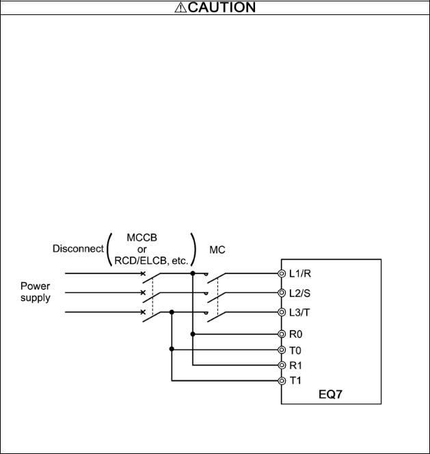
6.All circuits with terminals L1/R, L2/S, L3/T, R0, T0, R1, T1 must have a common disconnect and be connected to the same pole of the disconnect if the terminals are connected to the power supply.
7.When using the inverter as a UL Enclosed Type (UL TYPE1), purchase Type 1 kit (option) and mount it on the inverter as instructed.
viii
Conformity with UL standards and CSA standards (cUL-listed for Canada) (continued)
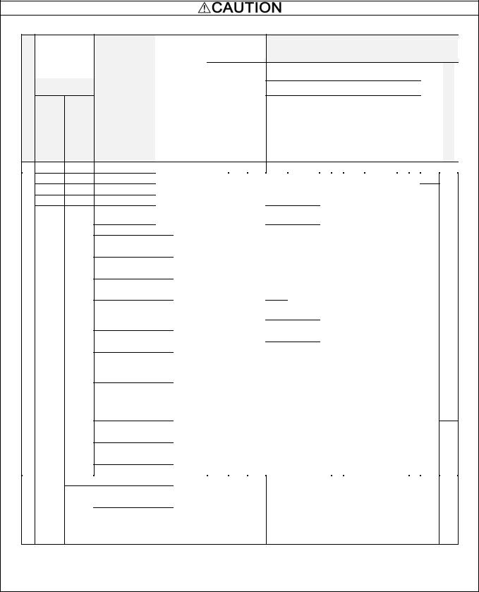
8. Install UL certified fuses or circuit breaker between the power supply and the inverter, referring to the table below.
| <![if ! IE]> <![endif]>voltage |
Nominal |
|
applied motor |
|
(HP) |
|
|
| <![if ! IE]> <![endif]>supply |
|
|
| <![if ! IE]> <![endif]>Power |
Three- |
Single- |
phase |
phase |
|
|
|
0.50.25
10.5
21
31.5
|
5 |
|
|
|
3 |
|
7.5 |
|
|
|
|
|
|
|
|
10 |
5 |
|
|
|
|
15 |
7.5 |
|
|
|
|
20 |
|
|
|
10 |
|
25 |
|
| <![if ! IE]> <![endif]>V |
|
|
|
|
|
| <![if ! IE]> <![endif]>230 |
30 |
15 |
|
|
|
|
40 |
20 |
|
|
|
|
50 |
25 |
|
|
|
|
60 |
|
|
|
30 |
|
75 |
|
|
|
|
|
|
|
|
100 |
|
|
|
40 |
|
125 |
|
|
|
|
|
|
|
|
150 |
50 |
|
|
|
Inverter type
EQ7-20P5-C
EQ7-2001-C
EQ7-2002-C
EQ7-2003-C
EQ7-2005-C
EQ7-2007-C
EQ7-2010-C
EQ7-2015-C
EQ7-2020-C
EQ7-2025-C
EQ7-2030-C
EQ7-2040-C
EQ7-2050-C
EQ7-2060-C
EQ7-2075-C
EQ7-2100-C
EQ7-2125-C
EQ7-2150-C
|
|
|
|
|
|
|
|
Required |
|
|||||
|
|
|
|
|
|
<![if ! IE]> <![endif]>(A) |
|
|
torque |
|
||||
|
|
|
|
|
|
|
|
|
|
|
|
|||
|
|
|
<![if ! IE]> <![endif]>Class J fuse size (A) |
|
|
<![if ! IE]> <![endif]>Circuit breaker trip size |
|
lb-in (N m) |
|
|||||
|
<![if ! IE]> <![endif]>CT/VT mode |
|
|
|
|
<![if ! IE]> <![endif]>Main terminal |
|
<![if ! IE]> <![endif]>Aux. control power |
<![if ! IE]> <![endif]>supply |
<![if ! IE]> <![endif]>Aux. Fan power supply |
|
|
||
|
|
|
|
|
|
|
|
|
|
|
|
|
|
|
|
|
10 |
|
5 |
|
10.6 |
- |
|
|
|
||||
|
|
15 |
|
10 |
|
(1.2) |
|
|
|
|||||
|
|
|
|
|
|
|
|
|
||||||
|
|
|
|
|
|
|
|
|
|
|
|
|
||
CT/ |
20 |
|
15 |
|
|
|
|
|
|
|
|
|||
30 |
|
20 |
|
15.9 |
|
|
|
|
|
|||||
|
VT |
|
|
|
|
|
|
|
||||||
|
|
|
|
|
|
|
(1.8) |
|
|
|
|
|
||
|
|
40 |
|
30 |
|
|
|
|
|
|
||||
|
|
|
|
|
|
|
|
|
|
|
||||
|
|
|
|
|
|
|
|
|
|
|
|
|
||
|
CT |
60 |
|
50 |
|
|
|
|
|
|
|
|
||
|
|
|
|
|
|
|
|
|
|
|
|
|
|
|
|
|
|
|
|
|
|
|
|
|
|
|
|
|
|
|
VT |
75 |
|
75 |
|
30.9 |
|
|
|
|
|
|||
|
CT |
|
|
|
|
|
|
|
||||||
|
|
|
|
|
|
|
(3.5) |
|
|
|
|
|
||
|
VT |
100 |
100 |
|
|
|
|
|
||||||
|
|
|
|
|
|
|
|
|||||||
|
CT |
|
|
|
|
|
|
|
||||||
|
|
|
|
|
|
|
|
|
|
|
- |
|
|
|
|
VT |
|
|
|
|
|
|
|
|
|
|
|
|
|
|
|
|
|
|
|
|
|
|
|
|
|
|
|
|
|
CT |
150 |
125 |
|
|
|
|
|
|
|
||||
|
|
|
|
|
|
|
|
|
|
|
|
|
|
|
|
VT |
175 |
150 |
|
|
|
|
|
|
|
||||
|
CT |
51.3 |
|
|
|
|
|
|||||||
|
VT |
200 |
175 |
(5.8) |
|
|
|
|
|
|||||
|
CT |
|
|
10.6 |
|
|
|
|||||||
|
|
|
|
|
|
|
|
|
|
|
|
|
||
|
VT |
|
|
|
|
|
|
|
|
(1.2) |
|
|
|
|
|
|
|
|
|
|
|
|
|
|
|
|
|
|
|
|
CT |
250 |
200 |
|
|
|
|
|
|
|
||||
|
119.4 |
|
|
|
|
|
||||||||
|
|
|
|
|
|
|
|
|
|
|
|
|||
|
|
|
|
|
|
|
|
|
|
|
|
|
||
|
VT |
|
|
|
|
|
|
(13.5) |
|
|
|
|
|
|
|
350 |
250 |
|
|
|
|
|
|
|
|||||
|
CT |
|
|
|
|
|
|
|
|
|
|
|
|
|
|
VT |
400 |
300 |
|
|
|
|
|
|
|
||||
|
CT |
238.9 |
|
|
|
|
|
|||||||
|
VT |
450 |
|
|
|
(27) |
|
|
|
|
|
|||
|
CT |
350 |
|
|
|
|
|
|
|
|||||
|
VT |
|
|
|
|
|
|
|
10.6 |
|
||||
|
|
|
|
|
|
|
|
|
|
|
||||
|
500 |
|
|
|
|
|
|
|
(1.2) |
|
||||
|
CT |
|
|
|
|
|
|
|
||||||
|
|
|
|
|
|
|
|
|
||||||
|
VT |
|
|
|
|
|
|
|
|
|
|
|
|
|
|
CT |
600 |
400 |
424.7 |
|
|
|
|
|
|||||
|
|
|
|
|
|
|
|
(48) |
|
|
|
|
|
|
|
VT |
700 |
500 |
|
|
|
|
|
|
|
||||
|
|
|
|
|
|
|
|
|
|
|
|
|
|
|
Wire size
AWG (mm2)
|
|
|
Main terminal |
|
|
<![if ! IE]> <![endif]>powercontrolAux. |
|
||||
|
|
|
|
|
|
|
|
|
|
<![if ! IE]> <![endif]>supply |
|
| <![if ! IE]> <![endif]> F)(140C60 wireCu |
<![if ! IE]> <![endif]> F)(167C75 wireCu |
<![if ! IE]> <![endif]>Remarks |
<![if ! IE]> <![endif]> F)(140C60 wireCu |
<![if ! IE]> <![endif]> F)(167C75 wireCu |
<![if ! IE]> <![endif]>Remarks |
||||||
L1/R, L2/S, L3/T |
|
U, V, W |
|
|
|
|
|||||
|
|
|
|
|
|
|
|
|
|
|
|
|
|
|
|
|
|
|
|
|
|
|
|
14 |
14 |
|
|
|
14 |
14 |
|
|
|
- |
|
|
|
|
|
|
|
||||||
|
|
|
|
|
|
|
|
||||
(2.1) |
(2.1) |
|
|
- |
(2.1) |
(2.1) |
|
|
- |
|
|
|
|
|
|
|
|
|
|
|
|
||
|
|
|
|
|
|
|
|
|
|
|
|
10 |
10 |
|
*1 |
|
12 |
12 |
|
|
|
|
|
(5.3) |
(5.3) |
|
|
(3.3) |
(3.3) |
|
|
|
|
|
|
|
|
|
|
*1 |
|
|
|
||||
|
8 |
|
|
|
|
|
|
|
|
|
|
|
|
|
|
|
|
|
|
|
|
||
|
|
|
|
|
|
|
|
|
|
|
|
|
(8.4) |
|
|
|
|
8 |
|
|
|
|
|
|
|
|
|
*2 |
|
|
|
*2 |
|
|
|
- |
|
|
|
- |
(8.4) |
|
|
|
|
||
|
|
|
*3 |
|
|
*3 |
|
|
|||
|
6 |
|
|
|
|
|
|
|
|
||
|
|
|
|
|
|
|
|
|
|
|
|
|
(13.3) |
|
|
|
|
|
|
|
|
|
|
|
|
|
|
|
|
|
|
|
|
|
|
|
4 |
|
|
|
|
6 |
|
|
|
|
|
3 |
|
|
|
4 |
|
|
|
|
|
||
(21.2) |
|
|
(13.3) |
|
|
|
|
||||
(26.7) |
|
|
(21.2) |
|
|
|
|
||||
|
|
|
- |
|
|
|
|
|
|
||
1 |
3 |
|
|
3 |
4 |
|
|
- |
|
|
|
|
|
|
|
|
|
|
|||||
(42.4) |
(26.7) |
|
|
(26.7) |
(21.2) |
|
|
|
|||
|
|
|
|
|
|
||||||
|
|
|
|
|
|
|
|
|
|
|
|
|
2 |
|
|
|
2 |
3 |
|
|
|
14 |
|
|
(33.6) |
|
|
(33.6) |
(26.7) |
|
|
||||
|
|
|
|
|
(2.1) |
||||||
|
|
|
|
|
|
|
|
|
|
||
|
|
|
|
|
|
2 |
|
|
|
*1 |
|
|
2/0 |
|
|
|
|
(33.6) |
|
|
*2 |
||
|
(67.4) |
|
|
|
1 |
|
|
|
|
|
|
|
|
|
|
|
|
(42.4) |
|
|
|
|
|
|
|
|
- |
|
|
|
|
|
|
|
|
|
3/0 |
|
|
|
1/0 |
|
|
|
|
|
|
|
|
|
|
|
(53.5) |
- |
|
|
|
||
|
(85) |
|
|
|
|
|
|
|
|||
|
|
|
*2 |
|
|
|
|
|
|
|
|
|
|
|
|
|
|
|
|
|
|
|
|
- |
4/0 |
|
|
|
4/0 |
|
|
|
|
|
|
(107.2) |
|
*3 |
|
|
|
*2 |
|
|
|||
|
|
- |
(107.2) |
|
|
|
|||||
|
2/0×2 |
|
|
|
*3 |
|
|
||||
|
|
|
|
|
|
|
|
|
|||
|
|
|
|
|
|
|
|
|
|
||
|
(67.4×2) |
|
|
|
|
|
|
|
|
|
|
|
3/0×2 |
|
|
|
3/0×2 |
|
|
|
|
||
|
(85×2) |
|
|
|
(85×2) |
|
|
|
|
||
|
|
|
|
|
|
|
|
|
|
||
|
4/0×2 |
|
|
|
4/0×2 |
|
|
|
|
||
|
(107.2×2 |
|
|
|
(107.2×2 |
|
|
|
|
||
|
) |
|
|
|
|
) |
|
|
|
|
|
|
|
|
|
|
|
|
|
|
|
||
|
300×2 |
|
|
|
300×2 |
|
|
|
|
||
|
(152×2) |
|
|
|
(152×2) |
|
|
|
|
||
|
|
|
|
|
|
|
|
|
|
|
|
<![endif]> Aux. fan power supply

-
14
(2.1)
Note 1: Control circuit terminals Tightening torque: 6.1 b-in (0.7 Nm), Recommended wire size: AWG 19 or 18 (0.65 to 0.82 mm2) *1 No terminal end treatment is required for connection.
*2 Use 75 C (167 F) Cu (Copper) wire only.
*3 The wire size of UL Open Type and Enclosed Type are common. Please contact us if UL Open Type exclusive wire is necessary.
ix
Conformity with UL standards and CSA standards (cUL-listed for Canada) (continued)
<![endif]> Power supply voltage
<![endif]>460 V
Nominal applied motor (HP)
Three- |
Single- |
phase |
phase |
0.50.25
10.5
21
31.5
7.53
10
5
15
7.5
20
10
25
30 15
40 20
50 25
60
30
75
100 40
125
50
150
60
200
250 75
300
100
350
Inverter type
| <![if ! IE]> <![endif]>CT/VT mode |
<![if ! IE]> <![endif]>Class J fuse size (A) |
<![if ! IE]> <![endif]>Circuit breaker trip size (A) |
|
|
|
Required |
Wire size |
|
torque |
||
AWG (mm2) |
||
b-in (Nm) |
||
|
|
<![if ! IE]> <![endif]>Main terminal |
|
<![if ! IE]> <![endif]>Aux. control power supply |
|
<![if ! IE]> <![endif]>Aux. Fan power supply |
|
|
|
|
|
|
|
|||
|
|
|
|
|
|
|
|
Main terminal
L1/R, L2/S, L3/T |
|
|
U, V, W |
|
||||||
|
|
|
|
|
|
|
|
|
|
|
| <![if ! IE]> <![endif]>60 C (140 F) |
<![if ! IE]> <![endif]>Cu wire |
<![if ! IE]> <![endif]>75 C (167 F) |
<![if ! IE]> <![endif]>Cu wire |
<![if ! IE]> <![endif]>Remarks |
<![if ! IE]> <![endif]>60 C (140 F) |
<![if ! IE]> <![endif]>Cu wire |
|
<![if ! IE]> <![endif]>75 C (167 F) |
<![if ! IE]> <![endif]>Cu wire |
<![if ! IE]> <![endif]>Remarks |
|
|
|
|
|
|
|
|
|
|
|
EQ7-40P5-C |
|
|
3 |
|
5 |
|
10.6 |
- |
|
|
EQ7-4001-C |
|
|
6 |
|
|
(1.2) |
|
|||
|
|
|
|
|
|
|
||||
EQ7-4002-C |
|
|
|
|
|
|
|
|
|
|
|
CT/ |
10 |
|
10 |
|
15.9 |
|
|
||
EQ7-4003-C |
|
VT |
15 |
|
15 |
|
|
|
||
|
|
|
(1.8) |
|
|
|||||
EQ7-4005-C |
|
|
20 |
|
20 |
|
|
|
||
|
|
|
|
|
|
|
||||
EQ7-4007-C |
|
|
30 |
|
30 |
|
|
|
|
|
|
|
CT |
|
|
|
|
|
|||
EQ7-4010-C |
|
|
|
|
|
|
|
|
|
|
|
VT |
40 |
|
40 |
|
|
|
|
||
|
|
|
|
|
|
|
||||
|
|
CT |
|
|
30.9 |
|
|
|||
EQ7-4015-C |
|
|
|
|
|
|
|
|
||
|
VT |
|
|
|
|
|
(3.5) |
|
|
|
|
|
|
|
|
|
|
|
|
||
|
|
60 |
|
50 |
|
|
|
|
||
|
|
CT |
|
|
|
|
|
|||
|
|
|
|
|
|
|
|
|
|
|
EQ7-4020-C |
|
|
|
|
|
|
|
|
|
|
|
VT |
|
|
|
|
|
|
|
|
|
|
|
70 |
|
60 |
|
|
|
|
||
|
|
|
|
|
|
|
|
|||
EQ7-4025-C |
|
CT |
|
|
|
|
|
|
|
|
|
VT |
90 |
|
75 |
|
|
|
- |
||
|
|
|
|
|
|
|||||
|
|
CT |
|
|
|
|
|
|||
EQ7-4030-C |
|
|
|
|
|
|
51.3 |
|
|
|
|
|
|
|
|
|
|
|
|
||
|
VT |
|
|
|
|
|
|
|
||
|
|
100 |
|
100 |
|
(5.8) |
|
|
||
|
|
CT |
|
|
|
|
||||
|
|
|
|
|
|
|
|
|
|
|
EQ7-4040-C |
|
|
|
|
|
|
|
|
|
|
|
VT |
|
|
|
|
|
|
|
|
|
|
|
125 |
|
|
|
|
|
|
||
|
|
|
|
|
|
|
|
|
||
EQ7-4050-C |
|
CT |
|
|
|
125 |
|
|
|
|
|
VT |
175 |
|
|
|
|
|
|
||
|
|
|
|
|
|
|
|
|||
|
|
CT |
|
|
|
|
10.6 |
|
||
EQ7-4060-C |
|
|
|
|
|
|
|
|
||
|
VT |
200 |
|
150 119.4 |
(1.2) |
|
||||
|
|
|
|
|||||||
|
|
CT |
|
|
|
|||||
EQ7-4075-C |
|
|
|
|
|
|
(13.5) |
|
|
|
|
VT |
|
|
|
200 |
|
|
|
|
|
|
|
|
|
|
|
|
|
|
||
|
|
CT |
|
|
|
|
|
|
|
|
|
|
|
|
|
|
|
|
|
|
|
EQ7-4100-C |
|
|
|
|
|
|
|
|
|
|
|
VT |
250 |
|
|
|
|
|
|
||
|
|
|
|
|
|
|
|
|||
|
|
|
|
|
|
|
|
|
|
|
|
|
CT |
|
|
|
175 |
|
|
|
|
|
|
|
|
|
|
|
|
|
||
|
|
|
|
|
|
|
|
|
|
|
EQ7-4125-C |
|
|
|
|
|
|
|
|
|
|
|
VT |
300 200 |
|
|
|
|
||||
|
|
|
|
|
|
|||||
|
|
|
|
|
|
|
|
238.9 |
|
|
EQ7-4150-C |
|
CT/VT |
|
350 |
|
250 |
|
(27) |
|
|
|
|
|
|
|
|
|||||
EQ7-4200-C |
|
CT/VT |
|
400 |
|
300 |
|
|
|
|
|
|
|
|
|
|
|
|
|
|
10.6 |
EQ7-4250-C |
|
CT/VT |
|
500 |
|
350 |
|
|
|
(1.2) |
|
|
|
|
|
|
|
||||
EQ7-4300-C |
|
CT/VT |
|
600 |
|
|
|
424.7 |
|
|
|
|
|
|
|
|
|
|
|
|
|
EQ7-4350-C |
|
CT/VT |
|
700 |
|
500 |
|
(48) |
|
|
EQ7-4450-C |
|
CT |
|
700 |
|
|
|
|
|
|
|
|
|
|
|
|
|
|
|
|
|
14 |
14 |
|
- |
14 |
14 |
|
- |
(2.1) |
(2.1) |
|
(2.1) |
(2.1) |
|
||
|
|
|
|
||||
|
12 |
|
|
|
|
|
|
|
|
|
|
|
|
|
|
|
(3.3) |
*1 |
|
|
12 |
*1 |
|
|
|
|
|
|
|
|
|
|
10 |
|
|
|
(3.3) |
|
|
|
|
|
|
|
|
|
|
- |
(5.3) |
|
*2 |
- |
|
|
*2 |
|
|
*3 |
10 |
|
*3 |
||
|
|
|
|
|
|||
|
|
|
|
|
|
|
|
|
8 |
|
|
|
(5.3) |
|
|
|
(8.4) |
|
|
|
|
|
|
|
|
|
|
8 |
|
|
|
|
|
|
|
|
|
|
|
|
|
|
|
|
(8.4) |
|
|
6 |
|
|
|
|
|
|
|
(13.3) |
6 |
|
|
6 |
|
|
|
|
|
|
|
|
|
||
4 |
(13.3) |
|
|
(13.3) |
6 |
|
|
|
|
|
|
(13.3) |
|
|
|
(21.2) |
|
|
|
|
|
|
|
|
|
- |
|
|
|
|
|
|
|
|
|
|
|
|
|
3 |
4 |
|
4 |
|
|
- |
|
|
|
|
|
||||
|
|
(21.2) |
|
|
|||
(26.7) |
(21.2) |
|
|
|
|
|
|
|
|
|
|
|
|
||
2 |
3 |
|
|
2 |
|
|
|
(33.6) |
(26.7) |
|
|
|
|
|
|
|
|
(33.6) |
|
|
|
||
|
2 |
|
|
2 |
|
|
|
|
|
|
|
|
|||
|
|
|
|
|
|
||
|
|
|
|
(33.6) |
|
|
|
|
(33.6) |
|
|
|
|
|
|
|
|
|
|
|
|
|
|
|
|
|
|
|
|
|
|
|
1/0 |
|
|
|
|
|
|
|
(53.5) |
|
|
|
|
|
|
|
|
|
|
1/0 |
|
|
|
|
|
|
|
|
|
|
|
|
|
- |
|
|
(53.5) |
- |
|
|
2/0 |
|
|
|
4/0 |
|
|
|
(67.4) |
|
|
|
(107.2) |
|
|
- |
|
|
*2 |
|
|
|
|
|
|
|
1/0×2 |
|
|
||
|
|
*3 |
|
|
*2 |
||
|
1/0×2 |
|
|
|
|||
|
|
- |
(53.5×2) |
|
|||
|
|
|
|
*3 |
|||
|
(53.5×2 |
|
|
|
|
|
|
|
|
|
|
2/0×2 |
|
||
|
|
|
|
|
|
||
|
) |
|
|
|
|
|
|
|
|
|
|
|
(67.4×2) |
|
|
|
|
|
|
|
|
|
|
|
3/0×2 |
|
|
|
3/0×2 |
|
|
|
(85×2) |
|
|
|
(85×2) |
|
|
|
|
|
|
|
|
|
|
|
4/0×2 |
|
|
|
250×2 |
|
|
|
(107.2× |
|
|
|
|
|
|
|
|
|
|
(127×2) |
|
|
|
|
2) |
|
|
|
|
|
|
|
|
|
|
|
|
|
|
|
250×2 |
|
|
|
300×2 |
|
|
|
(127×2) |
|
|
|
(152×2) |
|
|
|
|
|
|
|
|
|
|
|
<![if ! IE]> <![endif]>Aux. control power supply |
<![if ! IE]> <![endif]>Aux. fan power supply |
|
|
|
|
- |
|
|
|
|
|
|
|
-
14
(2.1)
*1
*2
14
(2.1)
*1
*2
Note 1: Control circuit terminals Tightening torque: 6.1 lb-in (0.7 Nm), Recommended wire size: AWG 19 or 18 (0.65 to 0.82 mm2) *1 No terminal end treatment is required for connection.
*2 Use 75 C (167 F) Cu (Copper) wire only.
*3 The wire size of UL Open Type and Enclosed Type are common. Please contact us if UL Open Type exclusive wire is necessary.
x

Conformity with UL standards and CSA standards (cUL-listed for Canada) (continued)
|
|
|
|
|
|
|
|
|
|
|
|
|
|
|
|
|
|
|
|
|
|
|
|
|
|
|
|
|
|
|
|
|
|
|
|
|
|
|
|
|
|
|
|
|
|
|
|
|
|
|
|
|
|
|
|
|
|
|
|
|
|
|
|
|
|
|
|
|
|
|
|
|
|
|
|
|
|
|
|
|
|
|
|
|
|
|
|
|
|
|
|
|
|
|
|
|
|
|
|
Required |
|
|
|
|
|
|
|
Wire size |
|
|
|
|
|
|
|
|
|
||||||||
|
|
|
|
|
|
|
|
|
|
|
|
|
|
|
torque lb-in |
|
|
|
|
|
|
|
|
|
|
|
|
|
|
|
|
||||||||||
|
|
|
|
|
|
|
|
|
|
|
|
|
|
|
|
|
|
|
|
|
|
|
2 |
|
|
|
|
|
|
|
|
|
|||||||||
|
|
Nominal applied |
|
|
|
|
|
|
|
|
<![if ! IE]> <![endif]>sizetripbreakerCircuit(A) |
|
|
|
|
|
|
|
|
|
|
|
|
|
|
|
AWG (mm ) |
|
|
|
|
|
|
|
|
|
|||||
|
<![if ! IE]> <![endif]>voltagesupplyPower |
motor |
|
|
|
|
|
<![if ! IE]> <![endif]>(A)sizefuseJClass |
|
|
|
|
|
|
(N m) |
|
|
|
|
|
|
|
|
|
|
|
|
|
|
|
|
|
|
|
|
|
|
||||
|
|
|
<![if ! IE]> <![endif]>modeCT//VT |
|
|
|
|
|
|
<![if ! IE]> <![endif]>terminalMain |
|
|
<![if ! IE]> <![endif]>supplypowercontrolAux. |
|
|
<![if ! IE]> <![endif]>supplypowerFanAux. |
|
<![if ! IE]> <![endif]>F)(140C60 wireCu |
|
<![if ! IE]> <![endif]>F)(167C75 wireCu |
|
|
<![if ! IE]> <![endif]>Remarks |
<![if ! IE]> <![endif]>F)(140C60 wireCu |
|
<![if ! IE]> <![endif]>F)(167C75 wireCu |
|
<![if ! IE]> <![endif]>Remarks |
|
<![if ! IE]> <![endif]>supplypowercontrolAux. |
|
|
<![if ! IE]> <![endif]>supplypowerfanAux. |
|
|||||||
|
|
|
|
|
|
|
|
|
|
|
|
|
|
|
|
|
|
|
|
|
|
|
|
|
|||||||||||||||||
|
|
HP |
|
|
|
|
|
|
|
|
|
|
|
|
|
|
|
|
|
|
|
|
|
|
Main terminal |
|
|
|
|
|
|
|
|
|
|||||||
|
|
|
|
|
|
|
|
|
|
|
|
|
|
|
|
|
|
|
|
|
|
|
L1/R, L2/S, L3/T |
|
U, V, W |
|
|
|
|
|
|
|
|
|
|||||||
|
|
|
|
Inverter type |
|
|
|
|
|
|
|
|
|
|
|
|
|
|
|
|
|
|
|
|
|
|
|
|
|
|
|
|
|
|
|
|
|
|
|
|
|
|
|
Three- |
Single- |
|
|
|
|
|
|
|
|
|
|
|
|
|
|
|
|
|
|
|
|
|
|
|
|
|
|
|
|
|
|
|
|
|
|
|
|
|
|
|
|
|
|
|
|
|
|
|
|
|
|
|
|
|
|
|
|
|
|
|
|
|
|
|
|
|
|
|
|
|
|
|
|
|
|
|
|
|
|
||
|
|
phase |
phase |
|
|
|
|
|
|
|
|
|
|
|
|
|
|
|
|
|
|
|
|
|
|
|
|
|
|
|
|
|
|
|
|
|
|
|
|
|
|
|
|
|
|
|
|
|
|
|
|
|
|
|
|
|
|
|
|
|
|
|
|
|
|
|
|
|
|
|
|
|
|
|
|
|
|
|
|
|
|
|
|
|
|
350 |
- |
|
|
CT |
800 |
|
|
|
|
|
|
|
|
|
|
|
|
|
300×2 |
|
|
|
|
|
350×2 |
|
|
|
|
|
|
|
|
|
|||||
|
|
|
|
|
|
|
|
|
|
|
|
|
|
|
|
|
(152×2) |
|
|
|
*2 |
|
(177×2) |
|
|
*2 |
|
|
|
|
|
|
|||||||||
|
|
|
|
EQ7-4450-C |
|
|
|
|
|
|
|
|
|
|
|
|
|
|
|
|
|
|
|
|
|
|
|
|
|
|
|
|
|
||||||||
|
|
450 |
|
|
VT |
|
|
|
600 |
|
|
|
|
|
|
|
|
|
|
400×2 |
|
|
|
*3 |
|
400×2 |
|
|
*3 |
|
|
|
|
|
|
||||||
|
|
|
|
|
|
|
|
|
|
|
|
|
|
|
|
|
|
|
|
|
|
|
|
|
|
|
|
||||||||||||||
|
|
|
|
|
|
|
|
|
|
|
|
|
|
|
|
|
|
(203×2) |
|
|
|
|
|
(203×2) |
|
|
|
|
|
|
|
|
|
||||||||
|
|
|
125 |
|
|
|
|
|
|
|
|
|
|
|
|
|
|
|
|
|
|
|
|
|
|
|
|
|
|
|
|
|
|
|
|
|
|
||||
|
|
|
|
|
|
|
|
|
|
|
|
|
|
|
|
|
|
|
|
|
|
|
|
|
|
|
|
|
|
|
|
|
|
|
|
|
|
|
|
|
|
|
|
400 |
|
|
|
|
1000 |
|
|
|
|
|
|
|
|
|
|
|
|
|
250×2 |
|
|
|
|
|
300×2 |
|
|
|
|
|
|
|
|
|
|||||
|
|
|
|
|
|
|
|
|
|
|
|
|
|
|
|
|
|
|
|
|
|
|
|
|
|
|
|
|
|
|
|
|
|
||||||||
|
|
|
EQ7-4500-C |
|
CT |
|
|
|
|
|
|
|
|
|
|
|
|
|
(127×2) |
|
|
|
|
|
(152×2) |
|
|
|
|
|
|
|
|
|
|||||||
|
|
|
|
|
|
|
|
|
|
|
|
|
|
|
|
|
|
|
|
|
|
|
|
|
|
|
|
|
|
|
|
||||||||||
|
|
450 |
- |
|
|
|
|
|
|
|
|
|
|
|
|
|
|
|
|
|
|
|
|
300×2 |
|
|
|
|
|
350×2 |
|
|
|
|
|
|
|
|
|
||
|
|
- |
150 |
EQ7-4600-C |
|
CT |
|
|
|
|
|
|
|
|
|
|
|
|
|
|
|
|
(152×2) |
|
|
|
|
|
(177×2) |
|
|
|
|
|
|
|
|
|
|||
|
|
|
|
|
|
|
|
|
|
|
|
|
|
|
|
|
|
|
|
|
|
|
|
|
|
|
|
|
|
|
|
|
|
|
|
|
|
|
|
|
|
|
|
500 |
EQ7-4500-C |
|
VT |
|
|
|
800 |
|
|
|
|
|
|
|
|
|
|
400×2 |
|
|
|
|
|
400×2 |
|
|
|
|
|
|
|
|
|
||||||
|
|
|
|
|
|
|
|
|
|
|
|
|
|
|
|
|
|
|
|
|
|
|
|
|
|
|
|
|
|
|
|||||||||||
|
|
- |
EQ7-4600-C |
|
CT |
|
|
|
|
|
|
|
|
|
|
|
|
|
|
|
|
|
|
|
|
|
|
|
|
|
|
|
|
|
|
||||||
|
|
|
|
|
|
|
|
|
|
|
|
|
|
|
|
|
|
|
|
(203×2) |
|
|
|
|
|
(203×2) |
|
|
|
14 |
|
14 |
|
||||||||
|
<![if ! IE]> <![endif]>V |
|
|
|
|
|
|
|
|
|
|
|
|
|
|
|
|
|
|
|
|
|
|
|
|
|
|
|
|
|
|
|
|
||||||||
|
- |
150 |
EQ7-4700-C |
|
CT |
|
|
|
|
|
|
|
|
|
|
|
|
|
|
|
|
|
|
|
|
|
|
|
|
|
|
||||||||||
|
|
1200 |
|
|
|
424.7 |
10.6 |
10.6 |
|
|
|
|
|
|
|
|
|
|
|
|
|
(2.1) |
(2.1) |
|
|||||||||||||||||
|
<![if ! IE]> <![endif]>460 |
|
|
|
|
|
|
|
|
|
- |
|
|
|
- |
|
- |
|
|
- |
|
|
|||||||||||||||||||
|
|
200 |
EQ7-4600-C |
|
VT |
|
|
|
|
|
|
|
|
|
|
|
|||||||||||||||||||||||||
|
|
|
|
|
|
(48) |
(1.2) |
(1.2) |
|
|
|
|
|
|
|
|
|
|
|
|
|
||||||||||||||||||||
|
|
|
|
|
|
|
|
|
|
|
|
|
|
|
|
*1 |
|
*1 |
|
||||||||||||||||||||||
|
600 |
|
|
|
|
|
|
|
|
500×2 |
|
|
|
|
|
500×2 |
|
|
|
|
|
||||||||||||||||||||
|
|
|
|
|
|
|
|
|
|
|
|
|
|
|
|
|
|
|
|
||||||||||||||||||||||
|
|
- |
EQ7-4700-C |
|
CT |
|
|
|
|
|
|
|
|
|
|
|
|
|
|
|
|
|
|
|
*2 |
|
|
|
*2 |
*2 |
|
*2 |
|
||||||||
|
|
|
|
|
|
|
|
|
|
|
|
|
|
|
|
|
|
|
|
(253×2) |
|
|
|
(253×2) |
|
|
|
||||||||||||||
|
|
- |
200 |
EQ7-4800-C |
|
CT |
|
|
|
|
|
|
|
|
|
|
|
|
|
|
|
|
|
|
|
*4 |
|
|
|
*4 |
|
|
|
|
|
|
|||||
|
|
|
|
|
|
|
|
|
|
|
|
|
|
|
|
|
|
|
|
|
|
|
|
|
|
|
|
|
|
|
|
|
|||||||||
|
|
|
|
|
|
|
|
|
|
|
|
|
|
|
|
|
|
|
|
|
|
|
|
|
|
|
|
|
|
|
|
|
|
|
|
|
|
|
|
|
|
|
|
700 |
EQ7-4700-C |
|
VT |
1400 |
1200 |
|
|
|
|
|
|
|
|
|
|
600×2 |
|
|
|
|
|
600×2 |
|
|
|
|
|
|
|
|
|
||||||||
|
|
|
|
|
|
|
|
|
|
|
|
|
|
|
|
|
|
|
|
|
|
|
|
|
|
|
|
||||||||||||||
|
|
- |
EQ7-4800-C |
|
CT |
|
|
|
|
|
|
|
|
|
|
|
|
|
(304×2) |
|
|
|
|
|
(304×2) |
|
|
|
|
|
|
|
|
|
|||||||
|
|
|
|
|
|
|
|
|
|
|
|
|
|
|
|
|
|
|
|
|
|
|
|
|
|
|
|
|
|
|
|
|
|
|
|
|
|
|
|
|
|
|
|
800 |
250 |
|
VT |
1600 |
|
|
|
|
|
|
|
|
|
|
|
|
|
350×3 |
|
|
|
|
|
400×3 |
|
|
|
|
|
|
|
|
|
||||||
|
|
|
|
|
|
|
|
|
|
|
|
|
|
|
|
|
|
|
|
|
|
|
|
|
|
|
|
|
|
|
|||||||||||
|
|
EQ7-4900-C |
|
CT |
|
|
|
|
|
|
|
|
|
|
|
|
|
(177×3) |
|
|
|
|
|
(203×3) |
|
|
|
|
|
|
|
|
|
||||||||
|
|
900 |
300 |
|
VT |
2000 |
1400 |
|
|
|
|
|
|
|
|
|
|
500×3 |
|
|
|
|
|
600×3 |
|
|
|
|
|
|
|
|
|
||||||||
|
|
|
|
|
|
|
|
|
|
|
|
|
|
|
|
|
|
|
|
|
|
|
|
|
|
|
|
||||||||||||||
|
|
|
|
CT |
|
|
|
|
|
|
|
|
|
|
(253×3) |
|
|
|
|
|
(304×3) |
|
|
|
|
|
|
|
|
|
|||||||||||
|
|
|
|
EQ7-41000-C |
|
|
|
|
|
|
|
|
|
|
|
|
|
|
|
|
|
|
|
|
|
|
|
|
|
|
|
|
|
|
|
|
|
|
|
||
|
|
1000 |
400 |
|
VT |
2200 |
1600 |
|
|
|
|
|
|
|
|
|
|
600×3 |
|
|
|
|
|
500×4 |
|
|
|
|
|
|
|
|
|
||||||||
|
|
|
|
|
|
|
|
|
|
|
|
|
|
(304×3) |
|
|
|
|
|
(253×4) |
|
|
|
|
|
|
|
|
|
||||||||||||
|
|
|
|
|
|
|
|
|
|
|
|
|
|
|
|
|
|
|
|
|
|
|
|
|
|
|
|
|
|
|
|
|
|
|
|
|
|
||||
|
Note:Control circuit terminals Tightening torque: 6.1 lb-in (0.7 Nm), Recommended wire size: AWG 19 or 18 (0.65 to 0.82 mm2) |
|
|
|
|||||||||||||||||||||||||||||||||||||
|
*1 |
No terminal end treatment is required for connection. |
|
|
|
|
|
|
|
|
|
|
|
|
|
|
|
|
|
|
|
|
|
|
|
|
|
|
|
|
|||||||||||
|
*2 Use 75 C (167 F) Cu (Copper) wire only. |
|
|
|
|
|
|
|
|
|
|
|
|
|
|
|
|
|
|
|
|
|
|
|
|
|
|
|
|
|
|
|
|
|
|
||||||
|
*3 The wire size of UL Open Type and Enclosed Type are common. Please contact us if UL Open Type exclusive wire is necessary. |
|
|
|
|||||||||||||||||||||||||||||||||||||
|
*4 |
It is showing the wire size for UL Open Type. |
|
|
|
|
|
|
|
|
|
|
|
|
|
|
|
|
|
|
|
|
|
|
|
|
|
|
|
|
|
|
|
|
|
|
|||||
|
|
See additional material INR-SI47-1365-JE for UL Enclosed Type (Pack with TYPE1 kit). |
|
|
|
|
|
|
|
|
|
|
|
|
|
|
|
|
|||||||||||||||||||||||
|
|
|
|
|
|
|
|
|
|
|
|
|
|
|
|
|
|
|
|
|
|
|
|
|
|
|
|
|
|
|
|
|
|
|
|
|
|
|
|
|
|
xi
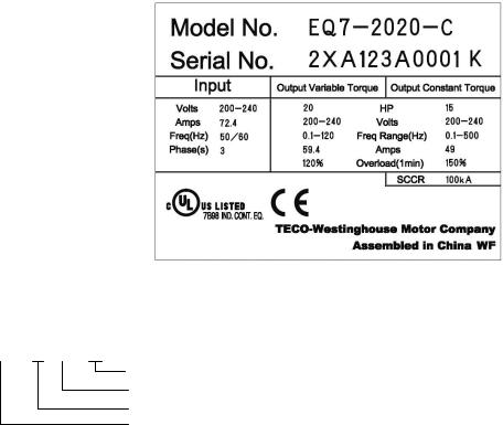
Chapter 1 Drive Model Identification
It is essential to verify the EQ7 drive nameplate and make sure that the EQ7 drive has the correct rating so it can be
used in your application with the proper sized AC motor.
Unpack the EQ7 drive and check the following:
(1)The EQ7 drive and quick start guide (this document) are contained in the package. The EQ7 DRIVE-2100-C / EQ7 DRIVE-4100-C and higher rated types come with a DC reactor (DCR). Be sure to connect the DCR.
(2)The EQ7 drive has not been damaged during transportation there should be no dents or parts missing.
(3)The EQ7 drive is the type you ordered. You can check the type and specifications on the main nameplate. (Main and sub nameplates are attached to the EQ7 drive and are located as shown below.)
(4)Check that the input voltage range meets the input power requirements.
(5)Ensure that for variable torque applications the motor rated current matches the variable torque FLA or for constant torque applications it matches the constant torque FLA. Verify that the output voltage rating on the EQ7 drive label meets the motor requirements (nameplate).
Figure 1.1 Nameplate
TYPE: Type of inverter
EQ7 – X XXX - X
C = Chassis; IP20 or IP00 HP Rating (Variable Torque) 2 = 230V, 4 = 460V
Product Type
1-1

1.1 Drive Models Constant Torque (CT) / Variable Torque (VT) HP Ratings
|
Voltage |
|
|
EQ7 DRIVE |
|
|
Variable Torque HP |
|
|
Constant Torque HP |
|
|
Frame / |
|
|
|
|
|
|
|
|
|
|
|
|||||
|
|
|
|
|
|
|
|
|||||||
|
|
|
|
|
|
|
|
|
Enclosure |
|
||||
|
|
|
|
|
|
|
|
|
|
|
|
|
|
|
|
|
|
|
EQ7-20P5-C |
0.5 |
|
0.5 |
|
|
Plastic |
||||
|
|
|
|
|
|
|
|
|
|
|
||||
|
|
|
|
EQ7-2001-C |
1 |
|
1 |
|
|
Plastic |
||||
|
|
|
|
|
|
|
|
|
|
|
||||
|
|
|
|
EQ7-2002-C |
2 |
|
2 |
|
|
Plastic |
||||
|
|
|
|
|
|
|
|
|
|
|
||||
|
|
|
|
EQ7-2003-C |
3 |
|
3 |
|
|
Plastic |
||||
|
|
|
|
|
|
|
|
|
|
|
||||
|
|
|
|
EQ7-2005-C |
5 |
|
5 |
|
|
Plastic |
||||
|
|
|
|
|
|
|
|
|
|
|
||||
|
|
|
|
EQ7-2007-C |
7.5 |
|
7.5 |
|
|
Plastic |
||||
|
|
|
|
|
|
|
|
|
|
|
||||
|
|
|
|
EQ7-2010-C |
10 |
|
7.5 |
|
|
Plastic |
||||
|
|
|
|
|
|
|
|
|
|
|
||||
|
|
|
|
EQ7-2015-C |
15 |
|
10 |
|
|
Plastic |
||||
|
230V |
|
EQ7-2020-C |
20 |
|
15 |
|
|
Plastic |
|||||
|
|
|
|
|
|
|
|
|
|
|
|
|
||
|
|
EQ7-2025-C |
25 |
|
20 |
|
|
Plastic |
||||||
|
|
|
|
|
|
|
||||||||
|
|
|
|
|
|
|
|
|
|
|
||||
|
|
|
|
EQ7-2030-C |
30 |
|
25 |
|
|
Plastic |
||||
|
|
|
|
|
|
|
|
|
|
|
||||
|
|
|
|
EQ7-2040-C |
40 |
|
30 |
|
|
Plastic |
||||
|
|
|
|
|
|
|
|
|
|
|
||||
|
|
|
|
EQ7-2050-C |
50 |
|
40 |
|
|
Sheet Metal |
||||
|
|
|
|
|
|
|
|
|
|
|
||||
|
|
|
|
EQ7-2060-C |
60 |
|
50 |
|
|
Sheet Metal |
||||
|
|
|
|
|
|
|
|
|
|
|
||||
|
|
|
|
EQ7-2075-C |
75 |
|
60 |
|
|
Sheet Metal |
||||
|
|
|
|
|
|
|
|
|
|
|
||||
|
|
|
|
EQ7-2100-C |
100 |
|
75 |
|
|
Sheet Metal |
||||
|
|
|
|
|
|
|
|
|
|
|
||||
|
|
|
|
EQ7-2125-C |
125 |
|
100 |
|
|
Sheet Metal |
||||
|
|
|
|
|
|
|
|
|
|
|
||||
|
|
|
|
EQ7-2150-C |
150 |
|
125 |
|
|
Sheet Metal |
||||
|
|
|
|
|
|
|
|
|
|
|
||||
|
|
|
|
EQ7-40P5-C |
0.5 |
|
0.5 |
|
|
Plastic |
||||
|
|
|
|
|
|
|
|
|
|
|
||||
|
|
|
|
EQ7-4001-C |
1 |
|
1 |
|
|
Plastic |
||||
|
|
|
|
|
|
|
|
|
|
|
||||
|
|
|
|
EQ7-4002-C |
2 |
|
2 |
|
|
Plastic |
||||
|
|
|
|
|
|
|
|
|
|
|
||||
|
|
|
|
EQ7-4003-C |
3 |
|
3 |
|
|
Plastic |
||||
|
|
|
|
|
|
|
|
|
|
|
||||
|
|
|
|
EQ7-4005-C |
5 |
|
5 |
|
|
Plastic |
||||
|
|
|
|
|
|
|
|
|
|
|
||||
|
|
|
|
EQ7-4007-C |
7.5 |
|
7.5 |
|
|
Plastic |
||||
|
|
|
|
|
|
|
|
|
|
|
||||
|
|
|
|
EQ7-4010-C |
10 |
|
7.5 |
|
|
Plastic |
||||
|
|
|
|
|
|
|
|
|
|
|
||||
|
|
|
|
EQ7-4015-C |
15 |
|
10 |
|
|
Plastic |
||||
|
|
|
|
|
|
|
|
|
|
|
||||
|
|
|
|
EQ7-4020-C |
20 |
|
15 |
|
|
Plastic |
||||
|
|
|
|
|
|
|
|
|
|
|
||||
|
|
|
|
EQ7-4025-C |
25 |
|
20 |
|
|
Plastic |
||||
|
|
|
|
|
|
|
|
|
|
|
||||
|
|
|
|
EQ7-4030-C |
30 |
|
25 |
|
|
Plastic |
||||
|
|
|
|
|
|
|
|
|
|
|
||||
|
|
|
|
EQ7-4040-C |
40 |
|
30 |
|
|
Plastic |
||||
|
|
|
|
|
|
|
|
|
|
|
||||
|
|
|
|
EQ7-4050-C |
50 |
|
40 |
|
|
Sheet Metal |
||||
|
|
|
|
|
|
|
|
|
|
|
||||
|
|
|
|
EQ7-4060-C |
60 |
|
50 |
|
|
Sheet Metal |
||||
|
460V |
|
|
|
|
|
|
|
|
|||||
|
|
EQ7-4075-C |
75 |
|
60 |
|
|
Sheet Metal |
||||||
|
|
|
|
|
|
|
|
|
|
|
||||
|
|
|
|
EQ7-4100-C |
100 |
|
75 |
|
|
Sheet Metal |
||||
|
|
|
|
EQ7-4125-C |
125 |
|
100 |
|
|
Sheet Metal |
||||
|
|
|
|
|
|
|
|
|
|
|
||||
|
|
|
|
EQ7-4150-C |
150 |
|
125/150* |
|
|
Sheet Metal |
||||
|
|
|
|
|
|
|
|
|
|
|
||||
|
|
|
|
EQ7-4200-C |
200 |
|
200* |
|
|
Sheet Metal |
||||
|
|
|
|
|
|
|
|
|
|
|
||||
|
|
|
|
EQ7-4250-C |
250 |
|
250* |
|
|
Sheet Metal |
||||
|
|
|
|
|
|
|
|
|
|
|
||||
|
|
|
|
EQ7-4300-C |
300 |
|
300* |
|
|
Sheet Metal |
||||
|
|
|
|
|
|
|
|
|
|
|
||||
|
|
|
|
EQ7-4350-C |
350 |
|
350* |
|
|
Sheet Metal |
||||
|
|
|
|
|
|
|
|
|
|
|
||||
|
|
|
|
EQ7-4450-C |
400/450 |
|
350 |
|
|
Sheet Metal |
||||
|
|
|
|
|
|
|
|
|
|
|
||||
|
|
|
|
EQ7-4500-C |
500 |
|
400/450* |
|
|
Sheet Metal |
||||
|
|
|
|
|
|
|
|
|
|
|
||||
|
|
|
|
EQ7-4600-C |
600 |
|
500* |
|
|
Sheet Metal |
||||
|
|
|
|
|
|
|
|
|
|
|
||||
|
|
|
|
EQ7-4700-C |
700 |
|
600* |
|
|
Sheet Metal |
||||
|
|
|
|
|
|
|
|
|
|
|
||||
|
|
|
|
EQ7-4800-C |
800 |
|
700* |
|
|
Sheet Metal |
||||
|
|
|
|
|
|
|
|
|
|
|
||||
|
|
|
|
EQ7-4900-C |
900 |
|
800 |
|
|
Sheet Metal |
||||
|
|
|
|
|
|
|
|
|
|
|
||||
|
|
|
|
EQ7-41000-C |
1000 |
|
900 |
|
|
Sheet Metal |
||||
|
|
|
|
|
|
|
|
|
|
|
|
|
|
|
Table 1.1
This table shows the Variable Torque and Constant Torque ratings for all EQ7 drive models.
* The HP ratings marked with (*) are suitable for constant torque V/F Control. Refer to EQ7 Instruction Manual chapter 11 for constant torque vector control HP ratings.
1-2
1.2 Installation and wiring practices
Mounting of the EQ7 drive is extremely important for accessibility as well as for the environment. Various EQ7 drive models are available and the mounting dimensions (footprint) may be different. Install the EQ7 drive in an environment that satisfies the requirements.
TECO-Westinghouse Motor Company strongly recommends installing inverters in a panel for safety reasons, in particular, when installing the ones that have an enclosure rating of IP00.
When installing the EQ7 drive in a place out of the specified environmental requirements, it is necessary to derate the inverter or consider the panel engineering design suitable for the special environment or the panel installation location. For details consult your TECO-Westinghouse Motor Company representative. The special environments listed below require using the specially designed panel or considering the panel installation location.
Installation environment
Environments |
Possible problems |
Sample measures |
Applications |
|
Highly concentrated |
Corrosive gases cause parts |
Any of the following measures may be |
Paper manufacturing, sewage |
|
sulfurizing gas or |
inside the inverter to corrode, |
necessary. |
disposal, sludge treatment, |
|
other corrosive gases |
resulting in an inverter |
-Mount the inverter in a sealed panel |
tire manufacturing, gypsum |
|
|
malfunction. |
with IP6X or air-purge mechanism. |
manufacturing, metal |
|
|
|
-Place the panel in a room free from |
processing, and a particular |
|
|
|
influence of the gases. |
process in textile factories. |
|
A lot of conductive |
Entry of conductive dust into |
Any of the following measures may be |
Wiredrawing machines, metal |
|
dust or foreign |
the inverter causes a short |
necessary. |
processing, extruding |
|
material (e.g., metal |
circuit. |
-Mount the inverter in a sealed panel. |
machines, printing presses, |
|
powders or shavings, |
|
-Place the panel in a room free from |
combustors, and industrial |
|
carbon fibers, or |
|
influence of the conductive dust. |
waste treatment. |
|
carbon dust) |
|
|
|
|
A lot of f brous or |
Fibrous or paper dust |
Any of the following measures may be |
Textile manufacturing and |
|
paper dust |
accumulated on the heat sink |
necessary. |
paper manufacturing. |
|
|
lowers the cooing effect. |
-Mount the inverter in a sealed panel |
|
|
|
Entry of dust into the inverter |
that shuts out dust. |
|
|
|
causes the electronic circuitry |
-Ensure a maintenance space for |
|
|
|
to malfunction. |
periodical cleaning of the heat sink in |
|
|
|
|
panel engineering design. |
|
|
|
|
-Employ external cooling when |
|
|
|
|
mounting the inverter in a panel for |
|
|
|
|
easy maintenance and perform |
|
|
|
|
periodical maintenance. |
|
|
High humidity or dew |
In an environment where a |
- |
Put a heating module such |
Outdoor installation. |
condensation |
humidifier is used or where the |
as a space heater in the panel. |
Film manufacturing line, |
|
|
air conditioner is not equipped |
|
|
pumps and food processing. |
|
with a dehumidifier, high |
|
|
|
|
humidity or dew condensation |
|
|
|
|
results, which causes a short- |
|
|
|
|
circuiting or malfunction of |
|
|
|
|
electronic circuitry inside the |
|
|
|
|
inverter. |
|
|
|
V bration or shock |
If a large vibration or shock |
-Insert shock-absorbing materials |
Installation of an inverter |
|
exceeding the |
exceeding the specified level is |
between the mounting base of the |
panel on a carrier or self- |
|
specified level |
applied to the inverter, for |
inverter and the panel for safe |
propelled machine. |
|
|
example, due to a carrier |
mounting. |
|
Ventilating fan at a |
|
running on seam joints of rails |
|
|
construction site or a press |
|
or blasting at a construction |
|
|
machine. |
|
site, the inverter structure gets |
|
|
|
|
damaged. |
|
|
|
Fumigation for export |
Halogen compounds such as |
-When exporting an inverter built in a |
Exporting. |
|
packaging |
methyl bromide used in |
panel or equipment, pack them in a |
|
|
|
fumigation corrodes some |
previously fumigated wooden crate. |
|
|
|
parts inside the inverter. |
-When packing an inverter alone for |
|
|
|
|
export, use a laminated veneer lumber |
|
|
|
|
(LVL). |
|
|
Table 1.2: Installation environment
1-3

Storage environment
The storage environment in which the inverter is stored after purchase is different from the operation environment.
For details, refer to the EQ7 DRIVE User's Manual, Chapter 2.
Wiring precautions
(1)Route the wiring of the control circuit terminals as far from the wiring of the main circuit as possible. Otherwise electric noise may cause malfunctions.
(2)Place the control circuit wires inside the inverter to keep them away from the live parts of the main circuit (such as the terminal block of the main circuit).
(3)If more than one motor is to be connected to a single inverter, the wiring length should be the sum of the length of the wires to the motors.
(4)Drive output terminals (U, V, W)
1)Connect these terminals to a 3-phase motor in the correct phase sequence. If the direction of motor rotation is incorrect, exchange any two of the U, V, and W phases.
2)Do not connect a power factor correction capacitor or surge suppressor to the inverter output.
3)If the cable from the inverter to the motor is very long, a high-frequency current may be generated by stray capacitance between the cables and result in an overcurrent trip of the inverter, an increase in leakage current, or a reduction in current indication precision.
When a motor is driven by a PWM-type inverter, the motor terminals may be subject to surge voltage generated by inverter element switching. If the motor cable (with 460 V series motors, in particular) is particularly long, surge voltage will deteriorate motor insulation. To prevent this, use the following guidelines:
 Inverter 7.5 HP and larger
Motor Insulation Level |
1000 V |
1300 V |
1600 V |
460 VAC Input Voltage |
66 ft (20 m) |
328 ft (100 m) |
1312 ft (400 m)* |
230 VAC Input Voltage |
1312 ft (400 m)* |
1312 ft (400 m)* |
1312 ft (400 m)* |
|
|
|
|
Inverter 5 HP and smaller |
|
|
|
Motor Insulation Level |
1000 V |
1300 V |
1600 V |
460 VAC Input Voltage |
66 ft (20 m) |
165 ft (50 m)* |
165 ft (50 m)* |
230 VAC Input Voltage |
328 ft (100 m)* |
328 ft (100 m)* |
328 ft (100 m)* |
*For this case the cable length is determined by secondary effects and not voltage spiking.
•When a motor protective thermal O/L relay is inserted between the inverter and the motor, the thermal O/L relay may malfunction (particularly in the 460 V series), even when the cable length is 165 ft (50 m) or less. To correct, insert a filter or reduce the carrier frequency. (Use function code F26 "Motor sound".)
•For the vector control mode, wiring length is 328 ft (100 m) or less.
(5) When an output circuit filter is inserted in the secondary circuit or the wiring between the inverter and the motor is long, a voltage loss occurs due to reactance of the filter or wiring so that the insufficient voltage may cause output current oscillation or a lack of motor output torque. To avoid it, select the constant torque load by setting the function code F37 (Load Selection/Auto Torque Boost/Auto Energy Saving Operation 1) to "1" and keep the inverter output voltage at a higher level by configuring H50/H52 (Non-linear V/f Pattern, Frequency) and H51/H53 (Non-linear V/f Pattern, Voltage).
1-4

Precautions for connection of peripheral equipment
(1) Phase-advancing capacitors for power factor correction
Do not mount a phase-advancing capacitor for power factor correction in the inverter's input (primary) or output (secondary) circuit. Mounting it in the input (primary) circuit takes no effect. To correct the inverter power factor, use an optional DC reactor (DCR). Mounting it in the output (secondary) circuit causes an overcurrent trip, disabling operation.
An overvoltage trip that occurs when the inverter is stopped or running with a light load is assumed to be due to surge current generated by open/close of phase-advancing capacitors in the power system. An optional DC/AC reactor (DCR/ACR) is recommended as a measure to be taken at the inverter side.
Input current to an inverter contains a harmonic component that may affect other motors and phase-advancing capacitors on the same power supply line. If the harmonic component causes any problems, connect an optional DCR/ACR to the inverter. In some cases, it is necessary to insert a reactor in series with the phase-advancing capacitors.
(2) Power supply lines (Application of a DC/AC reactor)
Use an optional DC reactor (DCR) when the capacity of the power supply transformer is 500 kVA or more and is 10 times or more the inverter rated capacity or when there are thyristor-driven loads. If no DCR is used, the percentage-reactance of the power supply decreases, and harmonic components and their peak levels increase. These factors may break rectifiers or capacitors in the converter section of the inverter, or decrease the capacitance of the capacitors.
If the input voltage unbalance rate is 2% to 3%, use an optional AC reactor (ACR).
Voltage unbalance(%) = |
Max voltage (V) - Min voltage (V) |
×67 (IEC 61800- 3) |
|
Three - phase average voltage (V) |
|||
|
|
(3) DC reactor (DCR) for correcting the inverter input power factor (for suppressing harmonics)
To correct the inverter input power factor (to suppress harmonics), use an optional DCR. Using a DCR increases the reactance of inverter’s power source so as to decrease harmonic components on the power source lines and correct the power factor of the inverter.
DCR models |
|
|
|
Input power factor |
|
Remarks |
|
DCR2/4-/A/B |
|
|
Approx. 90% to 95% |
|
The last letter identifies the capacitance. |
||
DCR2/4- |
|
C |
|
|
Approx. 86% to 90% |
|
Exclusively designed for inverters of 50 HP or above. |
|
|
|
|
|
|||
|
|
|
|
|
|
|
|
For selecting DCR models, refer to Chapter 11 "SPECIFICATIONS."
(4)PWM converter for correcting the inverter input power factor
Using a PWM converter (High power-factor, regenerative PWM converter) corrects the inverter power factor up to nearly 100%. When combining an inverter with a PWM converter, disable the main power down detection by setting the function code H72 to "0." If the main power loss detection is enabled (H72 = 1 by factory default), the inverter interprets the main power as being shut down, ignoring an entry of a run command.
1-5
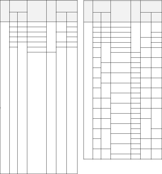
(5)Molded case circuit breaker (MCCB) or residual-current-operated protective device (RCD)/earth leakage circuit breaker (ELCB)
Install a recommended MCCB or RCD/ELCB (with overcurrent protection) in the primary circuit of the inverter to protect the wiring. Since using an MCCB or RCD/ELCB with a lager capacity than recommended ones breaks the protective coordination of the power supply system, be sure to select recommended ones. Also select ones with short-circuit breaking capacity suitable for the power source impedance.
Molded Case Circuit Breaker (MCCB) and Residual-Current-Operated Protective Device (RCD)/Earth Leakage
Circuit Breaker (ELCB)
|
Nominal |
|
|
Rated current of |
|||
|
applied |
|
|
||||
|
|
|
MCCB and |
||||
Power |
motor |
|
|
||||
|
CT/VT |
RCD/ELCB (A) |
|||||
(HP) |
|
||||||
supply |
Inverter type |
||||||
|
|
||||||
mode |
|
|
|||||
|
|
|
|
||||
voltage Three |
|
|
|
|
|||
Single- |
|
|
w/ DCR |
w/o |
|||
|
- |
phase |
|
|
DCR |
||
|
phase |
|
|
|
|||
|
0.5 |
0.25 |
EQ7-20P5-C |
|
|
5 |
|
|
1 |
0.5 |
EQ7-2001-C |
|
5 |
10 |
|
|
|
|
|||||
|
2 |
1 |
EQ7-2002-C |
CT/VT |
10 |
15 |
|
|
3 |
1.5 |
EQ7-2003-C |
20 |
|||
|
|
|
|||||
|
5 |
|
EQ7-2005-C |
|
20 |
30 |
|
|
7.5 |
3 |
EQ7-2007-C |
|
30 |
50 |
|
|
|
|
|
||||
|
|
|
|
|
EQ7-2010-C |
CT |
|
|
|
|
|
|
|
|
|
|
|
|
|
10 |
|
5 |
|
VT |
40 |
75 |
|||
|
|
|
|||||||
|
|
|
|
||||||
|
EQ7-2015-C |
CT |
|||||||
|
|
|
|
|
|
|
|
||
|
|
|
|
|
|
|
|
|
|
15 |
|
7.5 |
|
VT |
50 |
100 |
|||
|
|
|
|||||||
|
|
|
|
||||||
|
EQ7-2020-C |
CT |
|||||||
|
|
|
|
|
|
|
|
||
|
|
|
|
|
|
|
|
|
|
20 |
|
|
|
VT |
75 |
125 |
|||
|
|
|
|
||||||
|
|
|
|
|
|||||
|
|
EQ7-2025-C |
CT |
||||||
|
|
|
|
|
|
|
|
||
|
|
|
10 |
|
|
|
|
|
|
25 |
|
|
VT |
|
150 |
||||
|
|
|
|
|
|||||
|
|
|
|
|
|
||||
|
|
EQ7-2030-C |
CT |
|
|||||
230 V |
|
|
|
|
100 |
|
|
||
|
|
|
|
|
|
|
|||
|
|
|
|
VT |
|
|
|||
30 |
|
15 |
|
|
|
175 |
|||
|
|
|
|
|
|||||
|
EQ7-2040-C |
CT |
|
||||||
|
|
|
|
|
|
|
|
||
|
|
|
|
|
|
|
|
|
|
40 |
|
20 |
|
VT |
150 |
200 |
|||
|
|
|
|||||||
|
|
|
|
||||||
|
EQ7-2050-C |
CT |
|||||||
|
|
|
|
|
|
|
|
||
|
|
|
|
|
|
|
|
|
|
50 |
|
25 |
|
VT |
175 |
250 |
|||
|
|
|
|||||||
|
|
|
|
||||||
|
EQ7-2060-C |
CT |
|||||||
|
|
|
|
|
|
|
|
||
|
|
|
|
|
|
|
|
|
|
60 |
|
|
|
VT |
200 |
300 |
|||
|
|
|
|
||||||
|
|
|
|
|
|||||
|
|
EQ7-2075-C |
CT |
||||||
|
|
|
|
|
|
|
|
||
|
|
|
|
|
|
|
|
|
|
75 |
|
30 |
|
VT |
250 |
350 |
|||
|
|
|
|||||||
|
|
|
|
|
|||||
|
|
EQ7-2100-C |
CT |
||||||
|
|
|
|
|
|
|
|
||
|
|
|
|
|
|
|
|
|
|
100 |
|
|
|
VT |
350 |
|
|
||
|
|
|
|
|
|
||||
|
|
|
|
|
|
|
|||
|
|
|
EQ7-2125-C |
CT |
|
|
|||
|
|
|
|
|
|
|
|
||
|
|
|
|
|
|
|
|
|
|
125 |
|
40 |
|
VT |
400 |
-- |
|||
|
|
|
|||||||
|
|
|
|
|
|
|
|||
|
|
|
EQ7-2150-C |
CT |
|
|
|||
|
|
|
|
|
|
|
|
||
|
|
|
|
|
|
|
|
|
|
150 |
|
50 |
|
VT |
350 |
|
|
||
|
|
|
|
|
|||||
|
Nominal |
|
|
Rated current of |
|||
|
applied |
|
|
||||
|
|
|
MCCB and |
||||
Power |
motor |
|
|
||||
|
CT/VT |
RCD/ELCB (A) |
|||||
(HP) |
|
||||||
supply |
Inverter type |
||||||
|
|
||||||
mode |
|
|
|||||
voltage Three |
|
|
|
|
|||
Single- |
|
|
w/ DCR |
w/o |
|||
|
- |
phase |
|
|
DCR |
||
|
phase |
|
|
|
|||
|
0.5 |
0.25 |
EQ7-40P5-C |
|
|
5 |
|
|
1 |
0.5 |
EQ7-4001-C |
|
5 |
||
|
|
|
|||||
|
2 |
1 |
EQ7-4002-C |
CT/VT |
|
10 |
|
|
3 |
1.5 |
EQ7-4003-C |
|
15 |
||
|
|
10 |
|||||
|
5 |
|
EQ7-4005-C |
|
20 |
||
|
|
|
|
||||
|
|
|
EQ7-4007-C |
|
|
|
|
|
7.5 |
3 |
|
CT |
15 |
30 |
|
|
|
|
EQ7-4010-C |
|
|
||
|
|
|
|
|
|
||
|
10 |
|
|
VT |
20 |
40 |
|
|
|
|
CT |
||||
|
|
5 |
EQ7-4015-C |
|
|
||
|
|
VT |
|
|
|||
|
15 |
|
|
30 |
50 |
||
|
|
|
CT |
||||
|
|
|
EQ7-4020-C |
|
|
||
|
|
7.5 |
VT |
|
|
||
|
20 |
|
|
40 |
60 |
||
|
|
|
CT |
||||
|
|
|
EQ7-4025-C |
|
|
||
|
|
|
|
|
|
||
460 V |
25 |
10 |
|
VT |
40 |
75 |
|
|
|
|
CT |
||||
|
|
|
EQ7-4030-C |
|
|
||
|
|
|
|
|
|
||
|
30 |
15 |
|
VT |
50 |
100 |
|
|
|
CT |
|||||
|
|
|
EQ7-4040-C |
|
|
||
|
|
|
|
|
|
||
|
40 |
20 |
|
VT |
75 |
|
|
|
|
CT |
|
||||
|
|
|
EQ7-4050-C |
|
125 |
||
|
|
|
VT |
|
|||
|
50 |
25 |
|
|
|
||
|
|
CT |
|
|
|||
|
|
|
EQ7-4060-C |
100 |
|
||
|
|
|
VT |
|
|||
|
60 |
|
|
|
150 |
||
|
|
|
CT |
|
|||
|
|
|
EQ7-4075-C |
|
|
||
|
|
30 |
VT |
|
|
||
|
75 |
|
|
125 |
200 |
||
|
|
|
CT |
||||
|
|
|
EQ7-4100-C |
|
|
||
|
|
|
|
|
|
||
|
100 |
40 |
|
VT |
175 |
-- |
|
|
EQ7-4125-C |
CT |
|||||
|
|
|
|
|
|||
1-6

Molded Case Circuit Breaker (MCCB) and Residual- |
Leakage Circuit Breaker (ELCB) |
Current-Operated Protective Device (RCD)/Earth |
|
|
Nominal |
|
|
Rated current of |
|||
|
applied |
|
|
||||
|
|
|
MCCB and |
||||
Power |
motor |
|
|
||||
|
CT/VT |
RCD/ELCB (A) |
|||||
supply |
(HP) |
Inverter type |
|||||
mode |
|
|
|||||
voltage |
Three |
Single- |
|
|
w/o |
||
|
|
|
|||||
|
- |
|
|
w/ DCR |
|||
|
phase |
|
|
DCR |
|||
|
phase |
|
|
|
|||
|
|
|
|
|
|
||
|
125 |
|
EQ7-4125-C |
VT |
200 |
|
|
|
50 |
|
|
|
|||
|
EQ7-4150-C |
CT |
|
||||
|
|
|
|
||||
|
|
|
|
|
|
||
|
150 |
|
CT/VT |
250 |
|
||
|
|
|
|
||||
|
|
|
|
|
|||
|
|
|
CT |
|
|||
|
|
|
|
|
|
||
|
|
|
EQ7-4200-C |
|
|
|
|
|
200 |
60 |
CT/VT |
300 |
|
||
|
|
|
|||||
|
|
|
|
|
|||
|
|
EQ7-4250-C |
CT |
|
|||
|
|
|
|
|
|||
|
|
|
|
|
|
||
|
250 |
75 |
CT/VT |
350 |
|
||
|
|
|
|||||
|
|
|
|
|
|||
460 V |
EQ7-4300-C |
CT/VT |
|
-- |
|||
|
|
|
|||||
300 |
|
500 |
|||||
|
|
|
|||||
|
|
|
|
|
|||
|
100 |
EQ7-4350-C |
CT/VT |
|
|||
|
|
|
|
||||
|
350 |
|
|
||||
|
|
|
|
|
|
||
|
|
|
CT |
|
|
||
|
|
|
|
|
|
||
|
350 |
- |
EQ7-4450-C |
600 |
|
||
|
|
|
|||||
|
|
|
|
|
|
|
|
|
450 |
125 |
|
VT |
|
|
|
|
|
|
|
|
|
||
|
400 |
EQ7-4500-C |
CT |
|
|
||
|
|
|
|
||||
|
|
|
|
|
|||
|
450 |
- |
800 |
|
|||
|
|
|
|
||||
|
|
|
|
|
|
|
|
|
- |
150 |
EQ7-4600-C |
CT |
|
|
|
|
|
|
|
|
|
|
|
|
Nominal |
|
|
Rated current of |
|||
|
applied |
|
|
||||
Power |
|
|
MCCB and |
||||
motor |
|
CT/VT |
|||||
supply |
Inverter type |
RCD/ELCB (A) |
|||||
(HP) |
|||||||
mode |
|||||||
voltage |
|
|
|
||||
Three- |
Single- |
|
|
w/ DCR |
w/o |
||
|
|
|
|||||
|
phase |
phase |
|
|
DCR |
||
|
|
|
|
||||
|
|
|
|
||||
|
500 |
150 |
EQ7-4500-C |
VT |
|
|
|
|
|
|
|
|
|
||
|
- |
EQ7-4600-C |
CT |
800 |
|
||
|
|
|
|||||
|
|
|
|
|
|
|
|
|
- |
150 |
EQ7-4700-C |
CT |
|
|
|
|
|
|
|
|
|
|
|
|
600 |
200 |
EQ7-4600-C |
VT |
|
|
|
|
|
|
|
|
|
||
|
- |
EQ7-4700-C |
CT |
|
|
||
|
|
|
|
||||
|
|
|
|
|
|
|
|
|
- |
200 |
EQ7-4800-C |
CT |
|
|
|
|
|
|
|
|
|
||
460 V |
700 |
EQ7-4700-C |
VT |
1200 |
-- |
||
|
|||||||
|
|
|
|
|
|
||
|
- |
EQ7-4800-C |
CT |
|
|
||
|
|
|
|
||||
|
|
|
|
|
|
||
|
|
|
VT |
|
|
||
|
|
|
|
|
|
||
|
800 |
250 |
|
|
|
|
|
|
EQ7-4900-C |
CT |
|
|
|||
|
|
|
|
|
|||
|
|
|
|
|
|
||
|
900 |
300 |
VT |
1400 |
|
||
|
|
|
|||||
|
|
|
|
||||
|
EQ7-41000-C |
CT |
|
||||
|
|
|
|
|
|||
|
|
|
|
|
|
||
|
1000 |
400 |
VT |
1600 |
|
||
|
|
|
|||||
|
|
|
|
|
|
|
|
If no zero-phase current (earth leakage current) detective device such as a ground-fault relay is installed in the upstream power supply line in order to avoid the entire power supply system's shutdown undesirable to factory operation, install a residual-current-operated protective device (RCD)/earth leakage circuit breaker (ELCB) individually to inverters to break the individual inverter power supply lines only.
Otherwise, a fire could occur.
(6)Magnetic contactor (MC) in the inverter input (primary) circuit
Avoid frequent ON/OFF operation of the magnetic contactor (MC) in the input circuit; otherwise, the inverter failure may result. If frequent start/stop of the motor is required, use FWD/REV terminal signals or the  /
/  keys on the inverter's keypad.
The frequency of the MC's ON/OFF should not be more than once per 30 minutes. To assure 10-year or longer service life of the inverter, it should not be more than once per hour.
1-7

•From the system's safety point of view, it is recommended to employ such a sequence that shuts down the magnetic contactor (MC) in the inverter input circuit with an alarm output signal ALM issued on inverter's programmable output terminals. The sequence minimizes the secondary damage even if the inverter breaks.
When the sequence is employed, connecting the MC's primary power line to the inverter's auxiliary control power input makes it possible to monitor the inverter's alarm status on the keypad.
•The breakdown of a braking unit or misconnection of an external braking resistor may trigger that of the inverter's internal parts (e.g., charging resistor). To avoid such a breakdown linkage, introduce an MC and configure a sequence that shuts down the MC if a DC link voltage establishment signal is not issued within three seconds after the MC is switched on.
For the braking transistor built-in type of inverters, assign a transistor error output signal DBAL on inverter's programmable output terminals to switch off the MC in the input circuit.
(7)Magnetic contactor (MC) in the inverter output (secondary) circuit
If a magnetic contactor (MC) is inserted in the inverter's output (secondary) circuit for switching the motor to a commercial power or for any other purposes, it should be switched on and off when both the inverter and motor are completely stopped. This prevents the contact point from getting rough due to a switching arc of the MC. The MC should not be equipped with any main circuit surge killer.
Applying a commercial power to the inverter's output circuit breaks the inverter. To avoid it, interlock the MC on the motor's commercial power line with the one in the inverter output circuit so that they are not switched ON at the same time.
(8)Surge absorber/surge killer
Do not install any surge absorber or surge killer in the inverter's output (secondary) lines.
Noise reduction
If noise generated from the inverter affects other devices, or that generated from peripheral equipment causes the inverter to malfunction, follow the basic measures outlined below.
(1)If noise generated from the inverter affects the other devices through power wires or grounding wires:
-Isolate the grounding terminals of the inverter from those of the other devices.
-Connect a noise filter to the inverter power wires.
-Isolate the power system of the other devices from that of the inverter with an insulated transformer.
-Decrease the inverter's carrier frequency (F26).
1-8
(2)If induction or radio noise generated from the inverter affects other devices:
-Isolate the main circuit wires from the control circuit wires and other device wires.
-Put the main circuit wires through a metal conduit pipe, and connect the pipe to the ground near the inverter.
-Install the inverter into the metal panel and connect the whole panel to the ground.
-Connect a noise filter to the inverter's power wires.
-Decrease the inverter's carrier frequency (F26).
(3)When implementing measures against noise generated from peripheral equipment:
-For inverter's control signal wires, use twisted or shielded-twisted wires. When using shielded-twisted wires, connect the shield of the shielded wires to the common terminals of the control circuit.
-Connect a surge absorber in parallel with magnetic contactor's coils or other solenoids (if any).
Leakage current
A high frequency current component generated by insulated gate bipolar transistors (IGBTs) switching on/off inside the inverter becomes leakage current through stray capacitance of inverter input and output wires or a motor. If any of the problems listed below occurs, take an appropriate measure against them.
Problem |
|
Measures |
An earth leakage circuit |
1) |
Decrease the carrier frequency. |
breaker* that is |
2) |
Make the wires between the inverter and motor shorter. |
connected to the input |
3) |
Use an earth leakage circuit breaker with lower sensitivity than the one currently |
(primary) side has |
used. |
|
tripped. |
4) |
Use an earth leakage circuit breaker that features measures against the high |
*With overcurrent |
frequency current component. |
|
protection |
|
|
|
|
|
An external thermal relay |
1) |
Decrease the carrier frequency. |
was activated. |
2) |
Increase the current setting of the thermal relay. |
|
3) |
Use the electronic thermal overload protection built in the inverter, instead of the |
|
external thermal relay. |
|
Selecting inverter capacity
(1)To drive a general-purpose motor, select an inverter according to the nominal applied motor rating listed in the standard specifications table. When high starting torque is required or quick acceleration or deceleration is required, select an inverter with one rank higher capacity than the standard.
(2)Special motors may have larger rated current than general-purpose ones. In such a case, select an inverter that meets the following condition.
Inverter rated current > Motor rated current
1-9
1.3 Precautions in running inverters
Precautions for running inverters to drive motors or motor-driven machinery are described below.
Motor temperature
When an inverter is used to run a general-purpose motor, the motor temperature becomes higher than when it is operated with a commercial power supply. In the low-speed range, the motor cooling effect will be weakened, so decrease the output torque of the motor when running the inverter in the low-speed range.
Motor noise
When a general-purpose motor is driven by an inverter, the noise level is higher than that when it is driven by a commercial power supply. To reduce noise, raise carrier frequency of the inverter. Operation at 60 Hz or higher can also result in higher noise level.
Machine vibration
When an inverter-driven motor is mounted to a machine, resonance may be caused by the natural frequencies of the motor-driven machinery. Driving a 2-pole motor at 60 Hz or higher may cause abnormal vibration. If it happens, do any of the following:
-Consider the use of a rubber coupling or vibration-proof rubber.
-Use the inverter's jump frequency control feature to skip the resonance frequency zone(s).
-Use the vibration suppression related function codes that may be effective. For details, refer to the description of H80 in Chapter 4 "FUNCTION CODES" of the user manual.
1.4 Precautions in using special motors
When using special motors, please read the following section:
Explosion-proof motors
When driving an explosion-proof motor with an inverter, use a combination of a motor and an inverter that has been approved in advance.
Submersible motors and pumps
These motors have a larger rated current than general-purpose motors. Select an inverter with rated output current that is greater than that of the motor. These motors differ from general-purpose motors in thermal characteristics. Decrease the thermal time constant of the electronic thermal overload protection to match the motor rating.
Brake motors
For motors equipped with parallel-connected brakes, their power supply for braking must be supplied from the inverter input (primary) circuit. If the power supply for braking is mistakenly connected to the inverter's output (secondary) circuit, the brake may not work when the inverter output is shut down. Do not use inverters for driving motors equipped with series-connected brakes.
Geared motors
If the power transmission mechanism uses an oil-lubricated gearbox or speed changer/reducer, then continuous operation at low speed may cause poor lubrication. Avoid such operation.
Synchronous motors
It is necessary to take special measures suitable for this motor type. Contact your TECO-Westinghouse Motor Company representative for details.
Single-phase motors
Single-phase motors are not suitable for inverter-driven variable speed operation.
1-10
High-speed motors
If the reference frequency is set to 120 Hz or higher to drive a high-speed motor, test-run the combination of the inverter and motor beforehand to check it for the safe operation.
Precautions for use on single-phase power
An inverter is a device that converts alternating current of the input line to direct current via the ac-to-dc rectifier and then converts it to alternating current via the dc-to-ac switching inverter circuit in order to output the required alternating current. The EQ7 drive is designed to connect to the three-phase power and this manual stipulates the specifications for the use on the three-phase power.
If the inverter designed for connection to three-phase power runs on single-phase power, ripples (voltage fluctuation) on the DC link bus voltage rectified from the input power become larger than those in the inverter running on threephase power. The DC-voltage ripple affects the inverter output; that is, ripples could be superimposed on the output voltage or current, making control hard.
Accordingly, the inverter may not work in full performance or function correctly. To use the EQ7 drive on single-phase power, therefore, you need to take the following into account.
Output current
Select the inverter capacity to keep the output current within the specified level, referring to chapter 11. Output current exceeding the limit extremely increases voltage ripples on the DC link bus, impeding normal operation or resulting in an inverter breakdown.
Wiring
When connecting 230 V inverters of 60 HP or above or 460 V ones of 125 HP or above to single-phase power, use L1 and L3 phases since cooling fans and magnetic contactors inside the inverter are supplied with power via L1 and L3. Using L2 does not work cooling fans or magnetic contactors, causing abnormal heat, in the worst case, resulting in an inverter breakdown.
Connecting peripheral devices
For the specifications of circuit breakers and fuses to apply, refer to pages 1-6 and 1-7.
Configuring function codes
(1)Cancel the input phase loss protection of the protection/maintenance function with function code H98 (Bit 1 = 0). This is because the inverter judges single-phase power as a phase loss.
(2)Limit the drive mode to the VT / CT-V mode (Function code F80 = 0 or 1).
(3)Do not use "Vector control without speed sensor" or torque control. (Function codes F42 5, H18 = 0)
(4)"V/f control with slip compensation inactive" is recommended (F42 = 0). Any other drive control calculates the motor model using the motor parameters inside the inverter. As ripples on the DC link bus voltage become larger, therefore, calculation causes some errors so that the inverter may not provide the desired performance. Consider this problem before use. In particular, when using "Vector control with speed sensor" (F42 = 6), dancer control (J01 = 3), or brake signals (J68, J69, J70, etc.), assure the operation and safety of those speed sensors.
1-11
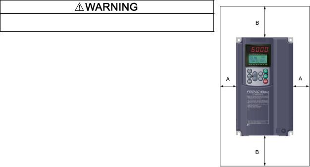
Chapter 2 Mounting and Wiring the Inverter
2.1 Operating Environment
Install the inverter in an environment that satisfies the requirements listed in Table 2.1.
|
Table 2.1 Environmental Requirements |
||
|
|
|
|
Item |
|
Specifications |
|
|
|
|
|
Site location |
Indoors |
|
|
|
|
|
|
Surrounding/ambient |
-10 to +50 C (14 to 122 F) (Note 1) |
||
temperature |
|
|
|
Relative humidity |
5 to 95% (No condensation) |
|
|
Atmosphere |
The inverter must not be exposed to dust, direct sunlight, |
||
|
corrosive gases, flammable gases, oil mist, vapor or water drops. |
||
|
Pollution degree 2 (IEC60664-1) (Note 2) |
||
|
The atmosphere can contain a small amount of salt. |
||
|
(0.01 mg/cm2 or less per year) |
|
|
|
The inverter must not be subjected to sudden changes in |
||
|
temperature that will cause condensation to form. |
||
|
|
|
|
Altitude |
3300 ft (1000 m) max. (Note 3) |
|
|
Atmospheric |
86 to 106 kPa |
|
|
pressure |
|
|
|
|
|
|
|
Vibration |
Inverters of |
Inverters of |
|
|
100 HP or below (230 V series) |
125 HP or above (230 V series) |
|
|
125 HP or below (460 V series) |
150 HP or above (460 V series) |
|
|
|
|
|
|
0.12 inch (3 mm) |
0.12 inch (3 mm) |
|
|
(Max. amplitude) |
(Max. amplitude) |
|
|
|
2 to less than 9 Hz |
2 to less than 9 Hz |
|
9.8 m/s2 9 to less than 20 Hz |
2 m/s29 to less than 55 Hz |
|
|
2 m/s2 |
20 to less than 55 Hz |
1 m/s255 to less than 200 Hz |
|
1 m/s2 |
55 to less than 200 Hz |
|
2.2 Installing the Inverter
(1) Mounting base
Install the inverter on a base made of metal or other non-flammable material.
Install the inverter on a base made of metal or other non-flammable material.
Otherwise, a fire could occur.
(2) Clearances
Ensure that the minimum clearances indicated in Figure 2.1 and Table 2.3 are maintained at all times. When mounting the inverter in the panel of your system, take extra care with ventilation inside the panel as the surrounding temperature easily rises. Do not mount the inverter in a small panel with poor ventilation.
When mounting two or more inverters
When mounting two or more inverters in the same unit or panel, install them side by side. When one must be mounted above the other, be sure to separate them with a partition plate, or the like, so that any heat radiating from an inverter will not affect the one/s above.
As long as the surrounding temperature is 40°C (104°F) or lower, inverters of 40 HP or below can be mounted side by side without any clearance between them.
Table 2.2 Output Current Derating
Factor in Relation to Altitude
Altitude |
Output current |
|
derating factor |
||
|
||
3300 ft (1000 m) |
1.00 |
|
or lower |
||
|
||
3300 to 4900 ft |
0.97 |
|
(1000 to 1500 m) |
||
|
||
4900 to 6600 ft |
0.95 |
|
(1500 to 2000 m) |
||
|
||
|
|
|
6600 to 8200 ft |
0.91 |
|
(2000 to 2500 m) |
||
|
||
8200 to 9800 ft |
0.88 |
|
(2500 to 3000 m) |
||
|
||
|
|
(Note 1) When inverters (40 HP or below) are mounted side-by-side without any clearance between them, the surrounding temperature should be within the range from -10 to +40 C (14 to 104 F). This specification also applies to the inverters (40 HP) equipped with a NEMA1 kit.
(Note 2) Do not install the inverter in an environment where it may be exposed to lint, cotton waste or moist dust or dirt which will clog the heat sink of the inverter. If the inverter is to be used in such an environment, install it in a dustproof panel.
(Note 3) If you use the inverter in an altitude above 3300 ft (1000 m), you should apply an output current derating factor as listed in Table 2.2.
|
Table 2.3 |
Clearances |
|
|
|
inch (mm) |
|
|
|
|
|
|
|
|
|
|
|
|
|
|
Inverter capacity |
|
A |
|
B |
|
C |
|
|
|
0.5 to 2 HP |
|
2.0 (50) |
|
|
|
0 |
|
|
|
|
|
|
|
3.9 (100) |
|
|
|
|
|
3 to 40 HP |
|
0.39 (10) |
|
|
|
|
||
|
|
|
|
|
|
|
|||
|
|
|
|
|
|
|
|
|
|
|
50 to 450 HP |
|
|
|
|
|
3.9 (100) |
|
|
|
|
|
2.0 (50) |
|
|
|
|
|
|
|
500 to 1000 HP |
|
|
5.9 (150) |
|
5.9 (150) |
|
Figure 2.1 Mounting Direction and |
|
|
|
|
|
|
|
||||
|
|
|
|
|
|
|
|
|
|
C: Space required in front of the inverter unit |
|
|
|
|
|
Required Clearances |
|||
2-1
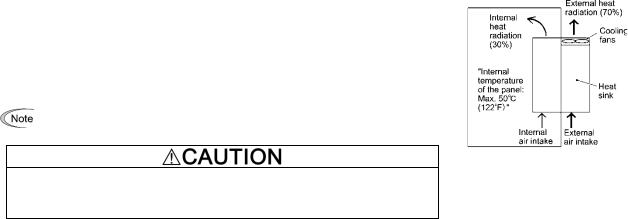
When employing external cooling
In external cooling, the heat sink, which dissipates about 70% of the total heat (total loss) generated into air, is situated outside the equipment or the panel. The external cooling, therefore, significantly reduces heat radiating inside the equipment or panel.
To employ external cooling for inverters (except DCR built-in type) of 40 HP or below, use the mounting adapter for external cooling (option); for those of 50 HP or above, simply change the positions of the mounting bases.
The DCR built-in type of 40 HP or below cannot employ external cooling.
Figure 2.2 External Cooling
Prevent lint, paper fibers, sawdust, dust, metallic chips, or other foreign materials from getting into the inverter or from accumulating on the heat sink.
Otherwise, a fire or accident could occur.
To utilize external cooling for inverters of 50 HP or above, change the positions of the top and bottom mounting bases from the edge to the center of the inverter as shown in Figure 2.3.
Screws differ in size and count for each inverter. Refer to the table below.
Table 2.4 Screw Size, Count and Tightening Torque
|
Base fixing screw |
Case fixing screw |
Tightening |
|
|
||||
|
||||
Inverter type |
torque |
|||
(Screw size and q'ty) |
(Screw size and q'ty) |
|||
|
lb-in (N m) |
|||
|
||||
|
|
|
||
EQ7-2050-C /EQ7-2060-C |
M6 20 |
M6 20 |
51.3 |
|
EQ7-4050-C |
5 pcs for upper side, |
|||
2 pcs for upper side |
(5.8) |
|||
EQ7-4100-C |
3 pcs for lower side |
|||
|
|
|||
|
|
|
|
|
EQ7-2075-C / EQ7-4100-C |
M6 20 |
M6 12 |
51.3 |
|
3 pcs each for upper and lower |
||||
EQ7-4125-C |
3 pcs for upper side |
(5.8) |
||
sides |
||||
|
|
|
||
|
|
|
|
|
EQ7-2125-C |
M5 12 |
M5 12 |
31.0 |
|
7 pcs each for upper and lower |
||||
EQ7-4150-C / EQ7-4200-C |
7 pcs for upper side |
(3.5) |
||
sides |
||||
|
|
|
||
|
|
|
|
|
|
M5 16 |
M5 16 |
31.0 |
|
EQ7-4250-C / EQ7-4300-C |
7 pcs each for upper and lower |
|||
7 pcs for upper side |
(3.5) |
|||
|
sides |
|||
|
|
|
||
|
|
|
|
|
EQ7-2150-C |
M5 16 |
M5 16 |
31.0 |
|
8 pcs each for upper and lower |
||||
EQ7-4350-C / EQ7-4450-C |
8 pcs for upper side |
(3.5) |
||
sides |
||||
|
|
|
||
|
|
|
|
|
|
M5 16 |
M5 16 |
|
|
|
2 pcs each for upper and lower |
2 pcs each for upper and lower |
31.0 |
|
EQ7-4500-C / EQ7-4600-C |
sides |
sides |
(3.5) |
|
EQ7-4700-C / EQ7-4800-C |
M6 20 |
M6 20 |
51.3 |
|
|
6 pcs each for upper and lower |
6 pcs each for upper and lower |
(5.8) |
|
|
sides |
sides |
|
|
|
|
|
|
|
|
M8 20 |
M8 20 |
119 |
|
EQ7-4900-C / EQ7-41000-C |
8 pcs each for upper and lower |
8 pcs each for upper and lower |
||
(13.5) |
||||
|
sides |
sides |
||
|
|
|||
|
|
|
|
1)Remove all base fixing screws and case fixing screws from the top of the inverter.
2)Move the top mounting base to the center of the inverter and secure it to the case fixing screw holes with the base fixing screws. (After changing the position of the top mounting base, some screws may be left unused.)
3)Remove the base fixing screws from the bottom of the inverter, move the bottom mounting base to the center of the inverter, and secure it with the base fixing screws, just as in step 2). (Inverters of 450 HP or below have no case fixing screws on the bottom.)
2-2
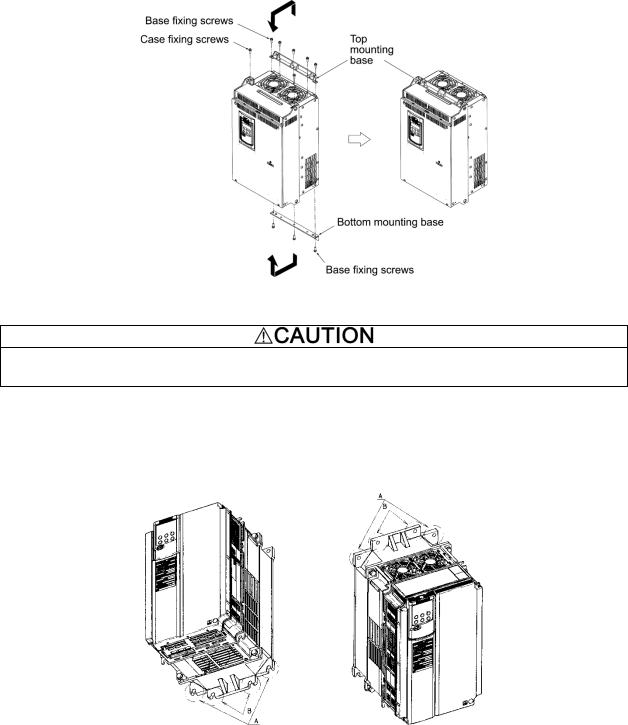
Figure 2.3 Changing the Positions of the Top and Bottom Mounting Bases
When changing the positions of the top and bottom mounting bases, use only the specified screws.
Otherwise, a fire or accident could occur.
(3) Mounting notes
The EQ7-2007-C / EQ7-4007-C through EQ7-2040-C / EQ7-4040-C should be mounted with four screws or bolts using screw holes A or B shown below. Note that, at each of the top and bottom of the inverter, the two screws or bolts should be located in a bilaterally symmetrical position.
2-3
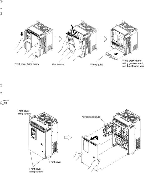
2.3 Wiring
Follow the procedure below. (In the following description, the inverter has already been installed.)
2.3.1 Removing and mounting the front cover and the wiring guide
(1) For inverters of 40 HP or below
First loosen the front cover fixing screw, slide the cover downward holding both sides, tilt it forward, and then pull it upward, as shown below.
While pressing the wiring guide upward, pull it out and forward.
After carrying out wiring (see Sections 2.3.2 through 2.3.6), put the wiring guide and the front cover back into place in the reverse order of removal.
Figure 2.4 Removing the Front Cover and the Wiring Guide (e.g EQ7-4020-C)
(2) For inverters of 50 to 1000 HP
Loosen the four front cover fixing screws, hold the cover with both hands, slide it upward slightly, and pull it forward, as shown below.
After carrying out wiring (see Sections 2.3.2 through 2.3.6), align the screw holes provided in the front cover with the screws on the inverter case, and then put the front cover back into place in the reverse order of removal.
To expose the control printed circuit board (control PCB), open the keypad enclosure.
Tightening torque: 15.9 lb-in (1.8 N m) (M4) 31.0 lb-in (3.5 N m) (M5)
Figure 2.5 Removing the Front Cover (e.g. EQ7-4050-C)
2-4

2.3.2 Screw specifications and recommended wire sizes
(1) Arrangement of main circuit terminals
The tables and figures given below show the screw specifications and wire sizes. Note that the terminal arrangements differ depending on the inverter types. In each of the figures, two grounding terminals ( G) are not exclusive to the power supply wiring (primary circuit) or motor wiring (secondary circuit).
Use crimp terminals covered with an insulation sheath or with an insulation tube.
The recommended wires for main circuit terminals are selected according to the sizes conforming to UL508C.
Table 2.5 Screw Specifications
Inverter type |
|
|
|
|
Screw specifications |
|
|
||||
|
|
|
|
|
|
|
Auxiliary control |
Auxiliary fan |
|||
|
|
|
Main circuit |
Grounding |
power input |
power input |
|||||
Three-phase |
Three-phase |
Refer to: |
terminals |
terminals |
terminals |
terminals |
|||||
|
|
|
|
[R0, T0] |
[R1, T1] |
||||||
230 V |
460 V |
|
|
|
|
|
|||||
|
Screw |
Tightening |
Screw |
Tightening |
Screw |
Tightening |
Screw |
Tightening |
|||
|
|
|
|||||||||
|
|
|
torque |
torque |
torque |
torque |
|||||
|
|
|
size |
size |
size |
size |
|||||
|
|
|
lb-in (N·m) |
lb-in (N·m) |
b-in (N·m) |
lb-in (N·m) |
|||||
|
|
|
|
|
|
|
|||||
EQ7-20P5-C |
EQ7-40P5-C |
Figure A |
M3.5 |
10.6 (1.2) |
M3.5 |
10.6 (1.2) |
-- |
-- |
|
|
|
|
|
|
|
||||||||
EQ7-2001-C |
EQ7-4001-C |
|
|
||||||||
|
|
|
|
|
|
|
|
|
|||
EQ7-2002-C |
EQ7-4002-C |
|
|
|
|
|
|
|
|
|
|
|
|
|
|
|
|
|
|
|
|
|
|
EQ7-2003-C |
EQ7-4003-C |
Figure B |
M4 |
15.9 (1.8) |
M4 |
15.9 (1.8) |
|
|
|
|
|
EQ7-2005-C |
EQ7-4005-C |
|
|
|
|
|
|
|
|
|
|
|
|
|
|
|
|
|
|
|
|
|
|
EQ7-2007-C |
EQ7-4007-C |
|
|
|
|
|
|
|
|
|
|
EQ7-2010-C |
EQ7-4010-C |
Figure C |
M5 |
31.0 (3.5) |
M5 |
31.0 (3.5) |
|
|
|
|
|
|
|
|
|
|
|
||||||
EQ7-2015-C |
EQ7-4015-C |
|
|
|
|
||||||
|
|
|
|
|
|
|
|
|
|||
|
|
|
|
|
|
|
|
|
-- |
-- |
|
EQ7-2020-C |
EQ7-4010-C |
|
|
|
|
|
|
|
|||
|
|
|
|
|
|
|
|
|
|||
|
|
|
|
|
|
|
|
|
|
|
|
EQ7-2025-C |
EQ7-4025-C |
|
|
|
|
|
|
|
|
|
|
|
|
|
|
|
|
|
|
|
|
|
|
EQ7-2030-C |
EQ7-4030-C |
Figure D |
M6 |
51.3 (5.8) |
M6 |
51.3 (5.8) |
|
|
|
|
|
EQ7-2040-C |
EQ7-4040-C |
|
|
|
|
|
|
|
|
|
|
|
EQ7-4050-C |
|
|
|
|
|
|
|
|
|
|
|
|
|
|
|
|
|
|
|
|
|
|
EQ7-2050-C |
EQ7-4060-C |
Figure E |
M8 |
119 (13.5) |
|
|
|
|
|
|
|
|
|
|
|
|
|
|
|||||
EQ7-4075-C |
|
|
|
|
|
|
|||||
|
|
|
|
|
|
|
|
|
|
||
|
|
|
|
|
|
|
|
|
|
|
|
|
EQ7-4100-C |
|
|
|
|
|
|
|
|
|
|
|
|
|
|
|
M8 |
119 (13.5) |
|
|
|
|
|
EQ7-2060-C |
|
|
|
|
M3.5 |
10.6 (1.2) |
|
|
|||
|
|
|
|
|
|
|
|
|
|||
EQ7-2075-C |
EQ7-4125-C |
Figure F |
|
|
|
|
|
|
|||
|
|
|
|
|
|
|
|
||||
EQ7-2100-C |
|
|
M10 |
239 (27) |
|
|
|
|
|
|
|
-- |
EQ7-4150-C |
Figure G |
|
|
|
|
|
|
|
|
|
|
|
|
|
|
|
|
|
|
|
||
-- |
EQ7-4200-C |
|
|
|
|
|
|
|
|
||
|
|
|
|
|
|
|
|
|
|||
|
|
|
|
|
|
|
|
|
|
|
|
EQ7-2125-C |
-- |
Figure M |
|
|
|
|
|
|
|
|
|
|
|
|
|
|
|
|
|
|
|
|
|
-- |
EQ7-4250-C |
Figure H |
|
|
|
|
|
|
|
|
|
|
|
|
|
|
|
|
|
|
|
||
-- |
EQ7-4300-C |
|
|
|
|
|
|
M3.5 |
10.6 (1.2) |
||
|
|
|
|
|
|
|
|||||
EQ7-2150-C |
EQ7-4350-C |
Figure I |
|
|
|
|
|
|
|||
|
|
|
|
|
|
|
|
||||
EQ7-4450-C |
|
|
|
|
|
|
|
|
|||
|
|
|
|
|
|
|
|
|
|
||
|
|
|
M12 |
425 (48) |
M10 |
239 (27) |
|
|
|
|
|
-- |
EQ7-4500-C |
Figure J |
|
|
|
|
|||||
-- |
EQ7-4600-C |
|
|
|
|
|
|
|
|
||
|
|
|
|
|
|
|
|
|
|||
|
|
|
|
|
|
|
|
|
|
|
|
-- |
EQ7-4700-C |
Figure K |
|
|
|
|
|
|
|
|
|
|
|
|
|
|
|
|
|
|
|
||
-- |
EQ7-4800-C |
|
|
|
|
|
|
|
|
||
|
|
|
|
|
|
|
|
|
|||
-- |
EQ7-4900-C |
Figure L |
|
|
|
|
|
|
|
|
|
-- |
EQ7-41000-C |
|
|
|
|
|
|
|
|
||
|
|
|
|
|
|
|
|
|
|||
|
|
|
|
|
|
|
|
|
|
|
|
When the inverter power is ON, a high voltage is applied to the following terminals.
Main circuit terminals: L1/R, L2/S, L3/T, P1, P(+), N(-), DB, U, V, W, R0, T0, R1, T1, AUX-contact (30A, 30B, 30C, Y5A, Y5C)
Insulation level
Main circuit - Enclosure Main circuit - Control circuit Relay output - Control circuit
:Basic insulation (Overvoltage category III, Pollution degree 2)
:Reinforced insulation (Overvoltage category III, Pollution degree 2)
:Reinforced insulation (Overvoltage category II, Pollution degree 2)
An electric shock may occur.
2-5
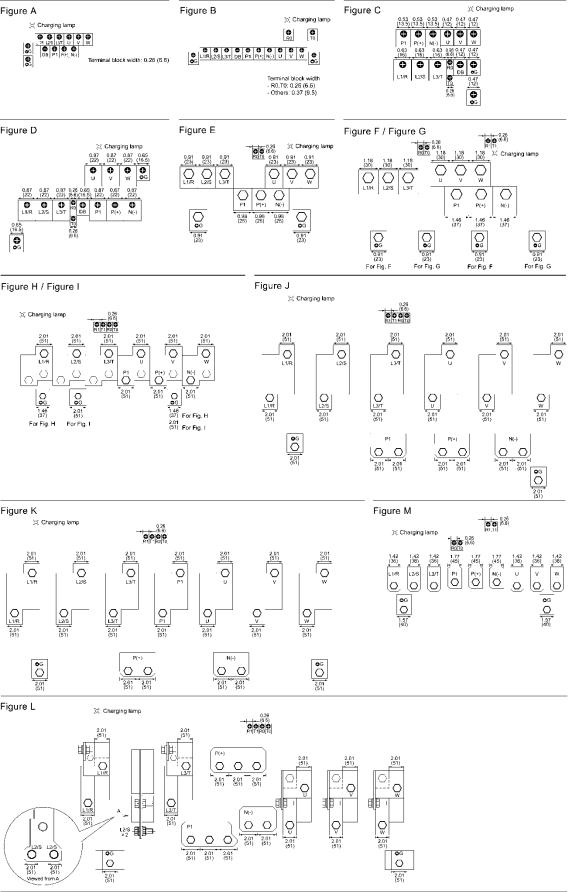
Unit: inch (mm)
*Refer to Section 2.3.3 (9).
2-6

Table 2.6 Recommended Wire Sizes
|
|
Inverter type |
|
|
Recommended wire size AWG (mm2) |
|
|||
Power supply |
Variable |
Constant |
CT-Vector |
L1/R, L2/S, |
Grounding |
|
DCR |
Braking |
|
|
|||||||||
voltage |
U, V, W |
resistor |
|||||||
Torque mode |
Torque mode |
mode |
L3/T |
[ G] |
[P1, P(+)] |
||||
|
|
[P(+), DB] |
|||||||
|
|
||||||||
|
|
|
|
|
|
|
|
||
|
EQ7-20P5-C |
EQ7-20P5-C |
EQ7-20P5-C |
|
14 (2.1) |
|
|
|
|
|
EQ7-2001-C |
EQ7-2001-C |
EQ7-2001-C |
14 (2.1) |
14 (2.1) |
14 (2.1) |
|
||
|
|
|
|||||||
|
EQ7-2002-C |
EQ7-2002-C |
EQ7-2002-C |
12 (3.3) |
|
||||
|
|
|
|
|
|||||
|
EQ7-2003-C |
EQ7-2003-C |
EQ7-2003-C |
|
|
|
|
|
|
|
EQ7-2005-C |
EQ7-2005-C |
EQ7-2005-C |
10 (5.3) |
10 (5.3) |
12 (3.3) |
10 (5.3) |
|
|
|
EQ7-2007-C |
EQ7-2007-C |
EQ7-2007-C |
|
|
|
|
||
|
|
|
|
|
|
||||
|
-- |
|
EQ7-2010-C |
8 (8.4) |
|
|
8 (8.4) |
10 (5.3) |
|
|
EQ7-2010-C |
EQ7-2010-C |
-- |
|
8 (8.4) |
||||
|
|
|
|
|
|||||
|
-- |
-- |
EQ7-2015-C |
|
8 (8.4) |
|
|
|
|
|
EQ7-2015-C |
EQ7-2015-C |
EQ7-2020-C |
6 (13.3) |
|
|
4 (21.2) |
|
|
Single-phase/ |
EQ7-2020-C |
EQ7-2020-C |
EQ7-2025-C |
4 (21.2) |
|
6 (13.3) |
3 (26.7) |
|
|
EQ7-2025-C |
EQ7-2025-C |
EQ7-2030-C |
3 (26.7) |
6 (13.3) |
4 (21.2) |
2 (33.6) |
|
||
Three-phase |
|
||||||||
EQ7-2030-C |
EQ7-2030-C |
EQ7-2040-C |
2 (33.6) |
|
3 (26.7) |
1 (42.4) |
|
||
230V |
|
|
|||||||
EQ7-2040-C |
EQ7-2040-C |
-- |
2/0 (67.4) |
4 (21.2) |
2 (33.6) |
2/0 (67.4) |
|
||
|
|
||||||||
|
-- |
|
EQ7-2050-C |
1 (42.4) |
|
||||
|
|
|
|
|
|
||||
|
EQ7-2050-C |
EQ7-2050-C |
-- |
3/0 (85) |
|
1/0 (53.5) |
4/0 (107.2) |
|
|
|
-- |
-- |
EQ7-2060-C |
3 (26.7) |
|
|
|||
|
|
|
|
|
|||||
|
EQ7-2060-C |
EQ7-2060-C |
EQ7-2075-C |
4/0 (107.2) |
|
4/0 (107.2) |
250 (127) |
|
|
|
EQ7-2075-C |
EQ7-2075-C |
EQ7-2100-C |
2/0 (67.4) 2 |
2 (33.6) |
|
350 (177) |
-- |
|
|
EQ7-2100-C |
EQ7-2100-C |
EQ7-2125-C |
3/0 (85) 2 |
3/0 (85) 2 |
||||
|
|
|
|
||||||
|
EQ7-2125-C |
EQ7-2125-C |
EQ7-2150-C |
4/0 (107.2) 2 |
1 (42.4) |
4/0 (107.2) |
500 (253) |
|
|
|
2 |
|
|||||||
|
|
|
|
|
|
|
|
||
|
EQ7-2150-C |
EQ7-2150-C |
-- |
300 (152) 2 |
1/0 (53.5) |
300 (152) 2 |
4/0 (107.2) |
|
|
|
|
|
|
|
|
|
2 |
|
|
|
EQ7-40P5-C |
EQ7-40P5-C |
EQ7-40P5-C |
|
|
|
|
|
|
|
EQ7-4001-C |
EQ7-4001-C |
EQ7-4001-C |
|
14 (2.1) |
|
|
|
|
|
EQ7-4002-C |
EQ7-4002-C |
EQ7-4002-C |
14 (2.1) |
14 (2.1) |
14 (2.1) |
|
||
|
|
|
|||||||
|
EQ7-4003-C |
EQ7-4003-C |
EQ7-4003-C |
|
|
|
|
|
|
|
EQ7-4005-C |
EQ7-4005-C |
EQ7-4005-C |
|
12 (3.3) |
|
|
|
|
|
EQ7-4007-C |
EQ7-4007-C |
EQ7-4007-C |
12 (3.3) |
|
|
12 (3.3) |
|
|
|
-- |
-- |
EQ7-4010-C |
|
12 (3.3) |
|
|||
|
|
|
|
|
|||||
|
EQ7-4010-C |
EQ7-4010-C |
EQ7-4015-C |
10 (5.3) |
10 (5.3) |
|
10 (5.3) |
10 (5.3) |
|
|
EQ7-4015-C |
EQ7-4015-C |
-- |
|
|
10 (5.3) |
|
|
|
|
-- |
-- |
EQ7-4020-C |
8 (8.4) |
|
8 (8.4) |
|
||
|
|
|
|
||||||
|
EQ7-4020-C |
EQ7-4020-C |
-- |
|
|
8 (8.4) |
|
||
|
|
|
|
|
|||||
|
-- |
-- |
EQ7-4025-C |
|
8 (8.4) |
|
|
|
|
|
EQ7-4025-C |
EQ7-4025-C |
EQ7-4030-C |
6 (13.3) |
6 (13.3) |
6 (13.3) |
|
||
|
|
|
|||||||
|
EQ7-4030-C |
EQ7-4030-C |
EQ7-4040-C |
|
|
|
|||
|
|
|
|
|
|
||||
|
EQ7-4040-C |
EQ7-4040-C |
-- |
4 (21.2) |
|
|
4 (21.2) |
|
|
|
-- |
-- |
EQ7-4050-C |
6 (13.3) |
|
|
|||
|
|
|
|
|
|||||
|
EQ7-4050-C |
EQ7-4050-C |
EQ7-4060-C |
3 (26.7) |
2 (33.6) |
2 (33.6) |
|
||
|
|
|
|||||||
|
EQ7-4060-C |
EQ7-4060-C |
EQ7-4075-C |
2 (33.6) |
|
1 (42.4) |
|
||
|
|
|
|
||||||
Single-phase/ |
EQ7-4075-C |
EQ7-4075-C |
EQ7-4100-C |
1/0 (53.5) |
|
|
|
|
|
Three-phase |
EQ7-4100-C |
EQ7-4100-C |
-- |
|
1/0 (53.5) |
1/0 (53.5) |
|
||
|
|
|
|||||||
460V |
|
4 (21.2) |
|
||||||
-- |
-- |
EQ7-4125-C |
2/0 (67.4) |
4/0 (107.2) |
|
|
|||
|
|
|
|
||||||
|
EQ7-4125-C |
EQ7-4125-C |
EQ7-4150-C |
|
3/0 (85) |
|
|||
|
|
|
|
|
|||||
|
EQ7-4150-C |
EQ7-4150-C |
EQ7-4200-C |
1/0 (53.5) |
3 (26.7) |
1/0 (53.5) |
4/0 (107.2) |
|
|
|
EQ7-4200-C |
EQ7-4200-C |
EQ7-4250-C |
2 (33.6) |
250 (127) |
|
|||
|
|
|
|
||||||
|
EQ7-4250-C |
EQ7-4250-C |
EQ7-4300-C |
3/0 (85) 2 |
2 (33.6) |
3/0 (85) 2 |
350 (177) |
|
|
|
EQ7-4300-C |
EQ7-4300-C |
EQ7-4350-C |
4/0 (107.2) 2 |
1 (42.4) |
250 (127) 2 |
600 (304) |
|
|
|
EQ7-4350-C |
EQ7-4350-C |
EQ7-4450-C |
250 (127) 2 |
|
300 (152) 2 |
4/0 (107.2) |
-- |
|
|
1/0 (53.5) |
|
2 |
|
|||||
|
|
|
|
|
|
|
|||
|
-- |
EQ7-4450-C |
-- |
300 (152) 2 |
|
350 (177) 2 |
250 (127) 2 |
|
|
|
EQ7-4450-C |
-- |
-- |
400 (203) 2 |
|
400 (203) 2 |
300 (152) 2 |
|
|
|
-- |
-- |
EQ7-4500-C |
250 (127) 2 |
2/0 (67.4) |
300 (152) 2 |
|
||
|
|
|
|||||||
|
-- |
EQ7-4500-C |
EQ7-4600-C |
300 (152) 2 |
|
350 (177) 2 |
350 (177) 2 |
|
|
|
EQ7-4500-C |
EQ7-4600-C |
EQ7-4700-C |
400 (203) 2 |
3/0 (85) |
400 (203) 2 |
400 (203) 2 |
|
|
|
EQ7-4600-C |
EQ7-4700-C |
EQ7-4800-C |
500 (253) 2 |
500 (253) 2 |
500 (253) 2 |
|
||
|
|
|
|||||||
|
EQ7-4700-C |
EQ7-4800-C |
-- |
600 (304) 2 |
4/0 (107.2) |
600 (304) 2 |
300 (152) 3 |
|
|
|
EQ7-4800-C |
-- |
EQ7-4900-C |
350 (177) 3 |
400 (203) 3 |
400 (203) 3 |
|
||
|
|
|
|||||||
|
EQ7-4900-C |
-- |
EQ7-41000-C |
500 (253) 3 |
250 (127) |
600 (304) 3 |
600 (304) 3 |
|
|
|
EQ7-41000-C |
-- |
-- |
600 (304) 3 |
350 (177) |
500 (253) 4 |
400 (203) 4 |
|
|
Note: The wire sizes above are specified for 75 C (167 F) copper (Cu) wire.
2-7
 Loading...