

Page 1
Page 2

I
Table of Contents
Preface.............................................................................................................................0-1
Chapter 1 Safety Precautions........................................................................................1-1
1.1 Before Supplying Power to the Inverter ......................................................................1-1
1.2 Wiring..........................................................................................................................1-2
1.3 Before Operation ........................................................................................................1-3
1.4 Parameters Setting.....................................................................................................1-3
1.5 Operation....................................................................................................................1-4
1.6 Maintenance, Inspection and Replacement................................................................1-5
1.7 Disposal of the Inverter...............................................................................................1-5
Chapter 2 Model Description.........................................................................................2-1
2.1 Nameplate Data.........................................................................................................2-1
2.2 Inverter Models-Motor Power Rating .........................................................................2-1
Chapter 3 Environment and Installation.......................................................................3-1
3.1 Environment................................................................................................................3-1
3.2 Installation...................................................................................................................3-2
3.2.1 Installation Spaces ...........................................................................................3-2
3.2.2 External View………………………………………………………………………...3-3
3.2.2.1 External View (IP00/ IP20)...................................................................3-3
3.2.2.2 External View (IP55)............................................................................3-6
3.2.3 Warning Labels................................................................................................3-7
3.2.4 Removing the Front Cover and Keypad...........................................................3-8
3.2.4.1 Standard Type (IP00/IP20) ............................................................3-9
3.2.4.2 Built-in Filter Type (IP20/IP00)........................................................3-15
3.2.4.3 Built-in Filter Type (IP55)................................................................3-16
3.3 Inverter Wiring ..........................................................................................................3-18
3.3.1 Wire Gauges and Tightening Torque............................................................3-18
3.3.2 Wiring Peripheral Power Devices .................................................................3-19
3.3.3 General Wiring Diagram...............................................................................3-21
3.3.4 Single/ Multi- Pump Dedicated Wiring Diagram............................................3-22
3.3.5 Wiring for Control Circuit Terminals..............................................................3-25
3.3.6 Wiring for Main Circuit Terminals .................................................................3-28
3.3.7 Wiring Precautions .......................................................................................3-37
3.3.8 Input Power and Cable Length.....................................................................3-39
3.4 Inverter Specifications..............................................................................................3-40
3.5 Inverter Derating Based on Carrier Frequency .......................................................3-43
3.6 Inverter Derating Based on Temperature.................................................................3-47
3.7 Inverter Dimensions.................................................................................................3-48
3.7.1 Standard Type (IP00/IP20)...........................................................................3-48
3.7.2 Models with Built-in Filter (IP00/IP20)...........................................................3-56
3.7.3 Models with Built-in Filter (IP55) ..................................................................3-58
Chapter 4 Keypad and Programming Functions..........................................................4-1
4.1 LED Keypad................................................................................................................4-1
4.1.1 Keypad Display and Keys...............................................................................4-1
4.1.2 Seven Segment Display Description...............................................................4-3
4.1.3 LED Indicator Description...............................................................................4-5
4.1.4 Power-up Monitor ...........................................................................................4-7
Page 3

II
4.1.5 Modifying Parameters/ Set Frequency Reference..........................................4-8
4.1.6 Operation Control .........................................................................................4-10
4.2 LCD keypad..............................................................................................................4-11
4.2.1 Keypad Display and Keys............................................................................4-11
4.2.2 Keypad Menu Structure ..............................................................................4-13
4.3 Parameters...............……………………………………………………………………..4-17
4.4 Description of Parameters .......................................................................................4-62
4.5 Built-in PLC Function.............................................................................................4-253
4.5.1 Basic Command .........................................................................................4-253
4.5.2 Basic Command Function...........................................................................4-254
4.5.3 Application Functions..................................................................................4-255
4.6 Modbus Protocol Descriptions ..............................................................................4-262
4.6.1 Communication Connection and Data Frame.............................................4-262
4.6.2 Register and Data Format ..........................................................................4-266
4.7 BacNET Protocol Descriptions ..............................................................................4-285
4.7.1 BACnet Services.........................................................................................4-285
4.7.2 BACnet Protocol Structure..........................................................................4-286
4.7.3 BACnet Specifications................................................................................4-287
4.7.4 BACnet Object Properties...........................................................................4-288
4.8 MetaSys N2 Communication Protocol ..................................................................4-291
4.8.1 Introduction and Setting..............................................................................4-291
4.8.2 MetaSys N2 Specification...........................................................................4-291
4.8.3 Definition of MetaSys N2 Communication Protocol ....................................4-292
4.8.4 MetaSys N2 Communication Protocol in F510 Model.................................4-293
Chapter 5 Check Motor Rotation and Direction ...........................................................5-1
Chapter 6 Speed Reference Command Configuration ................................................6-1
6.1 Reference from Keypad .............................................................................................6-1
6.2 Reference from External Analog Signal (0-10V / 4-20mA) ........................................ 6-2
6.3 Reference from Serial Communication RS485 (00-05=3)...........................................6-4
6.4 Reference from two Analog Inputs .............................................................................6-6
6.5 Change Frequency Unit from Hz to rpm ....................................................................6-6
Chapter 7 Operation Method Configuration (Run / Stop)...........................................7-1
7.1 Run/Stop from the Keypad (00-02=0) – Default Setting .............................................7-1
7.2 Run/Stop from External Switch / Contact or Pushbutton (00-02=1)...........................7-2
7.3 Run/Stop from Serial Communication RS485 (00-02=3)............................................7-3
Chapter 8 Motor and Application Specific Settings.....................................................8-1
8.1 Set Motor Nameplate Data (02-01, 02-05)..................................................................8-1
8.2 Acceleration and Deceleration Time (00-14, 00-15) ..................................................8-2
8.3 Torque Compensation Gain (01-10) ...........................................................................8-3
8.4 Automatic Energy Savings Function (11-19)...............................................................8-4
8.5 Emergency Stop .........................................................................................................8-6
8.6 Direct / Unattended Startup .......................................................................................8-7
8.7 Analog Output Setup...................................................................................................8-8
Chapter 9 Using PID Control for Constant Flow / Pressure Applications..................9-1
9.1 What is PID Control? ..................................................................................................9-1
Page 4

III
9.2 Connect Transducer Feedback Signal (10-01)..........................................................9-3
9.3 Engineering Units .......................................................................................................9-4
9.4 Sleep / Wakeup Function ...........................................................................................9-5
Chapter 10 Troubleshooting and Fault Diagnostics..................................................10-1
10.1 General .................................................................................................................10-1
10.2 Fault Detection Function .......................................................................................10-1
10.3 Warning / Self-diagnosis Detection Function ........................................................10-5
10.4 Auto-tuning Error .................................................................................................10-12
10.5 PM Motor Auto-tuning Error.................................................................................10-13
Chapter 11 Inverter Peripheral devices and Options.................................................11-1
11.1 Braking Resistors and Braking Units ......................................................................11-1
11.2 AC Line Reactors....................................................................................................11-4
11.2.1 200V Class AC Reactor Dimensions..........................................................11-5
11.2.2 400V Class AC Reactor Dimensions..........................................................11-6
11.3 Input Noise Filters ..................................................................................................11-7
11.4 Input Current and Fuse Specifications ...................................................................11-9
11.5 Other options .......................................................................................................11-11
11.6 Communication options .......................................................................................11-16
11.7 Profibus Communication Option Card ..................................................................11-17
11.7.1 Introduction...............................................................................................11-17
11.7.2 Specification of JN5-CM-PBUS ................................................................11-17
11.7.3 Wiring Diagram of JN5-CM-PBUS............................................................11-18
11.7.4 Installation ................................................................................................11-18
11.7.5 Descriptions of Terminals, LEDs and DIP switch......................................11-21
11.7.6 Related Parameters for Communication...................................................11-22
11.7.7 Profibus I/O List........................................................................................11-22
11.7.8 Error Massage..........................................................................................11-26
11.7.9 GSD File...................................................................................................11-26
11.8 Protective Cover ...................................................................................................11-28
Appendix-A Instructions for UL....................................................................................A-1
Page 5

0-1
Preface
The F510 product is an inverter designed to control a three-phase induction motor. Please
read this manual carefully to ensure correct operation, safety and to become familiar with
the inverter functions.
The F510 inverter is an electrical / electronic product and must be installed and handled by
qualified service personnel.
Improper handling may result in incorrect operation, shorter life cycle, or failure of this
product as well as the motor.
All F510 documentation is subject to change without notice. Be sure to obtain the latest
editions for use or visit our website at http://globalsa.teco.com.tw.
Available Documentation:
1. F510 Start-up and Installation Manual
2. F510 Instruction Manual
Read this instruction manual thoroughly before proceeding with installation, connections
(wiring), operation, or maintenance and inspection.
Ensure you have sound knowledge of the inverter and familiarize yourself with all safety
information and precautions before proceeding to operate the inverter.
Please pay close attention to the safety precautions indicated by the warning and
caution symbol.
Warning
Failure to ignore the information indicated by the warning symbol
may result in death or serious injury.
Caution
Failure to ignore the information indicated by the caution symbol
may result in minor or moderate injury and/or substantial property
damage.
Page 6
1-1
Chapter 1 Safety Precautions
1.1 Before Supplying Power to the Inverter
Warning
¾ The main circuit must be correctly wired. For single phase supply use input terminals
(R/L1, T/L3) and for three phase supply use input terminals (R/L1, S/L2, T/L3).
Terminals U/T1, V/T2, W/T3 must only be used to connect the motor. Connecting the
input supply to any of the U/T1, V/T2 or W/T3 terminals will cause damage to the
inverter.
Caution
¾ To avoid the front cover from disengaging or other physical damage, do not carry the
inverter by its cover. Support the unit by its heat sink when transporting. Improper
handling can damage the inverter or injure personnel, and should be avoided.
¾ To avoid the risk of fire, do not install the inverter on or near flammable objects. Install
on nonflammable objects such as metal surfaces.
¾ If several inverters are placed inside the same control panel, provide adequate
ventilation to maintain the temperature below 40°C/104°F (50°C/122°F without a dust
cover) to avoid overheating or fire.
¾ When removing or installing the digital operator, turn off the power first, and then
follow the instructions in this manual to avoid operator error or loss of display caused
by faulty connections.
Warning
¾ This product is sold subject to IEC 61800-3. In a domestic environment this product
may cause radio interference in which case the user may need to apply corrective
measures.
¾ Over temperature protection function on motor is disabled.
Page 7

1-2
1.2 Wiring
Warning
¾ Always turn OFF the power supply before attempting inverter installation and wiring of
the user terminals.
¾ Wiring must be performed by a qualified personnel / certified electrician.
¾ Make sure the inverter is properly grounded. (200V Class: Grounding impedance shall
be less than 100Ω. 400V Class: Grounding impedance shall be less than 10Ω.) It is
required to disconnect the ground wire in the control board to avoid the sudden surge
causing damage on electronic parts if it is improperly grounded.
¾ Please check and test emergency stop circuits after wiring. (Installer is responsible for
the correct wiring.)
¾ Never touch any of the input or output power lines directly or allow any input or output
power lines to come in contact with the inverter case.
¾ Do not perform a dielectric voltage withstand test (megger) on the inverter or this will
result in inverter damage to the semiconductor components.
Caution
¾ The line voltage applied must comply with the inverter’s specified input voltage. (See
product nameplate section 2.1)
¾ Connect braking resistor and braking unit to the designated terminals. (See section
3.3.5)
¾ Do not connect a braking resistor directly to the DC terminals P(+) and N(-),otherwise
fire may result.
¾ Use wire gauge recommendations and torque specifications. (See Wire Gauge and
Torque Specification section 3.3.1)。
¾ Never connect input power to the inverter output terminals U/T1, V/T2, W/T3.
¾ Do not connect a contactor or switch in series with the inverter and the motor.
¾ Do not connect a power factor correction capacitor or surge suppressor to the inverter
output。
¾ Ensure the interference generated by the inverter and motor does not affect
peripheral devices.
Page 8
1-3
1.3 Before Operation
Warning
¾ Make sure the inverter capacity matches the parameters 13-00 before supplying
power.
¾ Reduce the carrier frequency (parameter 11-01) If the cable from the inverter to the
motor is over 80 ft (25m). A high-frequency current can be generated by stray
capacitance between the cables and result in an overcurrent trip of the inverter, an
increase in leakage current, or an inaccurate current readout.
¾ Be sure to install all covers before turning on power. Do not remove any of the covers
while power to the inverter is on, otherwise electric shock may occur.
¾ Do not operate switches with wet hands, otherwise electric shock may result.
¾ Do not touch inverter terminals when energized even if inverter has stopped,
otherwise electric shock may result.
1.4 Parameter Setting
Caution
¾ Do not connect a load to the motor while performing an auto-tune.
¾ Make sure the motor can freely run and there is sufficient space around the motor
when performing a rotational auto-tune.
Page 9
1-4
1.5 Operation
Warning
¾ Be sure to install all covers before turning on power. Do not remove any of the covers
while power to the inverter is on, otherwise electric shock may occur.
¾ Do not connect or disconnect the motor during operation. This will cause the inverter
to trip and may cause damage to the inverter.
¾ Operations may start suddenly if an alarm or fault is reset with a run command active.
Confirm that no run command is active upon resetting the alarm or fault, otherwise
accidents may occur.
¾ Do not operate switches with wet hands, otherwise electric shock may result.
¾ An external emergency stop switch is enabled when parameter 08-30 is set for the
run permissive function.
¾ It provides an independent external hardware emergency switch, which emergently
shuts down the inverter output in the case of danger.
¾ If automatic restart after power recovery (parameter 07-00) is enabled, the inverter will
start automatically after power is restored.
¾ Make sure it is safe to operate the inverter and motor before performing a rotational
auto-tune.
¾ Do not touch inverter terminals when energized even if inverter has stopped,
otherwise electric shock may result.
¾ Do not check signals on circuit boards while the inverter is running.
¾ After the power is turned off, the cooling fan may continue to run for some time.
Caution
¾ Do not touch heat-generating components such as heat sinks and braking resistors.
¾ Carefully check the performance of motor or machine before operating at high speed,
otherwise Injury may result.
¾ Note the parameter settings related to the braking unit when applicable.
¾ Do not use the inverter braking function for mechanical holding, otherwise injury may
result.
¾ Do not check signals on circuit boards while the inverter is running.
Page 10
1-5
1.6 Maintenance, Inspection and Replacement
Warning
¾ Wait a minimum of 5 minutes after power has been turned OFF before starting an
inspection. Also confirm that the charge light is OFF and that the DC bus voltage has
dropped below 25Vdc. Wait a minimum of 15 minutes while inverter is over 20HP.
¾ Never touch high voltage terminals in the inverter.
¾ Make sure power to the inverter is disconnected before disassembling the inverter.
¾ Only authorized personnel should perform maintenance, inspection, and replacement
operations. (Take off metal jewelry such as watches and rings and use insulated
tools.)
Caution
¾ The Inverter can be used in an environment with a temperature range from 14° -104°F
(-10-40°C) and relative humidity of 95% non-condensing.
¾ The inverter must be operated in a dust, gas, mist and moisture free environment.
1.7 Disposal of the Inverter
Caution
¾ Please dispose of this unit with care as an industrial waste and according to your
required local regulations.
¾ The capacitors of inverter main circuit and printed circuit board are considered as
hazardous waste and must not be burned.
¾ The Plastic enclosure and parts of the inverter such as the top cover board will
release harmful gases if burned.
Page 11
2-1
P/N BARCODE
S/N BARCODE
Chapter 2 Model Description
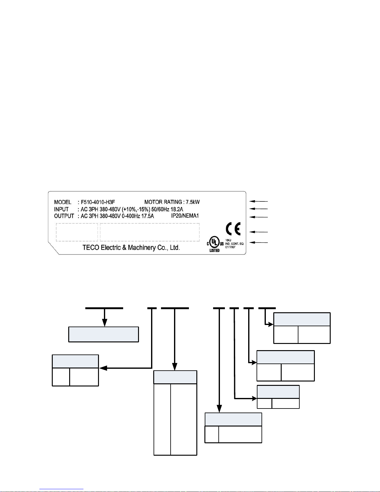
2.1 Nameplate Data
It is essential to verify the F510 inverter nameplate and make sure that the F510 inverter has the
correct rating so it can be used in your application with the proper sized AC motor.
Unpack the F510 inverter and check the following:
(1) The F510 inverter and quick setting guide are contained in the package.
(2) The F510 inverter has not been damaged during transportation there should be no dents or
parts missing.
(3) The F510 inverter is the type you ordered. You can check the type and specifications on the
main nameplate.
(4) Check that the input voltage range meets the input power requirements.
(5) Ensure that the motor HP matches the motor rating of the inverter.
2.2 Model Identification
F510InverterSeries
F510 - 4 010 - H 3 F
__
2:
4:
200V
400V
VoltageRating
005:
008:
150:
175:
215:
535:
800:
5HP
8HP
150HP
175HP
215HP
535HP
800HP
MotorRating
H:
C:
LEDOperator
LCDOperator
OperatorType
3: 3Ph
Input
Blank:
F:
NoRFI
RFIFiler
Noise Filter
ProtectionClass
Blank:
N4:
IP00/IP20
IP55
Inverter Model and Motor Rating
UL and CE Marks
Input Power Specifications
Output Power Specifications
Series No.
Page 12

2-2
Inverter Models – Motor Power Rating:
200V Class
Filter Operator
Voltage (Vac)
&
Frequency (Hz)
F510 Model
Motor
Power
(Hp)
Applied
Motor
(kW)
with without LED LCD
Protection
Class
(IP55)
F510-2005-H3 5 3.7 ◎ ◎
F510-2005-C3 5 3.7
◎ ◎
F510-2008-H3 7.5 5.5
◎ ◎
F510-2008-C3 7.5 5.5
◎ ◎
F510-2010-H3 10 7.5
◎ ◎
F510-2010-C3 10 7.5
◎ ◎
F510-2015-H3 15 11
◎ ◎
F510-2015-C3 15 11
◎ ◎
F510-2020-H3 20 15
◎ ◎
F510-2020-C3 20 15
◎ ◎
F510-2025-H3 25 18.5
◎ ◎
F510-2025-C3 25 18.5
◎ ◎
F510-2030-H3 30 22
◎ ◎
F510-2030-C3 30 22
◎ ◎
F510-2040-H3 40 30
◎ ◎
F510-2040-C3 40 30
◎ ◎
F510-2050-H3 50 37
◎ ◎
F510-2050-C3 50 37
◎ ◎
F510-2060-H3 60 45
◎ ◎
F510-2060-C3 60 45
◎ ◎
F510-2075-H3 75 55
◎ ◎
F510-2075-C3 75 55
◎ ◎
F510-2100-H3 100 75
◎ ◎
F510-2100-C3 100 75
◎ ◎
F510-2125-H3 125 94
◎
◎
F510-2125-C3 125 94
◎
◎
F510-2150-H3 150 112
◎
◎
F510-2150-C3 150 112
◎
◎
F510-2175-H3 175 130
◎
◎
3ph
200~240V
+10%/-15%
50/60Hz
F510-2175-C3 175 130
◎
◎
Note:
z Short Circuit Rating: 200V Class: 5KA.
Page 13

2-3
400V Class
Filter Operator
Voltage (Vac)
&
Frequency (Hz)
F510 Model
Motor
Power
(Hp)
Applied
Motor
(kW)
with without LED LCD
Protection
Class
(IP55)
F510-4005-H3 5 3.7 ◎ ◎
F510-4005-H3F 5 3.7
◎ ◎
F510-4005-C3 5 3.7
◎ ◎
F510-4005-C3F 5 3.7
◎ ◎
F510-4005-C3FN4 5 3.7
◎ ◎ ◎
F510-4008-H3 7.5 5.5
◎ ◎
F510-4008-H3F 7.5 5.5
◎ ◎
F510-4008-C3 7.5 5.5
◎ ◎
F510-4008-C3F 7.5 5.5
◎ ◎
F510-4008-C3FN4 7.5 5.5
◎ ◎ ◎
F510-4010-H3 10 7.5
◎ ◎
F510-4010-H3F 10 7.5
◎ ◎
F510-4010-C3 10 7.5
◎ ◎
F510-4010-C3F 10 7.5
◎ ◎
F510-4010-C3FN4 10 7.5
◎ ◎ ◎
F510-4015-H3 15 11
◎ ◎
F510-4015-H3F 15 11
◎ ◎
F510-4015-C3 15 11
◎ ◎
F510-4015-C3F 15 11
◎ ◎
F510-4015-C3FN4 15 11
◎ ◎ ◎
F510-4020-H3 20 15
◎ ◎
F510-4020-H3F 20 15
◎ ◎
F510-4020-C3 20 15
◎ ◎
F510-4020-C3F 20 15
◎ ◎
F510-4020-C3FN4 20 15
◎ ◎ ◎
F510-4025-H3 25 18.5
◎ ◎
F510-4025-H3F 25 18.5
◎ ◎
F510-4025-C3 25 18.5
◎ ◎
F510-4025-C3F 25 18.5
◎ ◎
F510-4025-C3FN4 25 18.5
◎ ◎ ◎
F510-4030-H3 30 22
◎ ◎
F510-4030-H3F 30 22
◎ ◎
F510-4030-C3 30 22
◎ ◎
F510-4030-C3F 30 22
◎ ◎
F510-4030-C3FN4 30 22
◎ ◎ ◎
F510-4040-H3 40 30
◎ ◎
F510-4040-H3F 40 30
◎ ◎
F510-4040-C3 40 30
◎ ◎
F510-4040-C3F 40 30
◎ ◎
3ph
380~480V
+10%/-15%
50/60Hz
F510-4040-C3FN4 40 30
◎ ◎ ◎
Page 14

2-4
Filter Operator
Voltage (Vac)
&
Frequency (Hz)
F510 Model
Motor
Power
(Hp)
Applied
Motor
(kW)
with without LED LCD
Protection
Class
(IP55)
F510-4050-H3 50 37 ◎ ◎
F510-4050-H3F 50 37
◎ ◎
F510-4050-C3 50 37
◎ ◎
F510-4050-C3F 50 37
◎ ◎
F510-4050-C3FN4 50 37
◎ ◎ ◎
F510-4060-H3 60 45
◎ ◎
F510-4060-H3F 60 45
◎ ◎
F510-4060-C3 60 45
◎ ◎
F510-4060-C3F 60 45
◎ ◎
F510-4060-C3FN4 60 45
◎ ◎ ◎
F510-4075-H3 75 55
◎ ◎
F510-4075-H3F 75 55
◎ ◎
F510-4075-C3 75 55
◎ ◎
F510-4075-C3F 75 55
◎ ◎
F510-4075-C3N4 75 55
◎ ◎
◎
F510-4100-H3 100 75
◎ ◎
F510-4100-C3 100 75
◎ ◎
F510-4100-C3N4 100 75
◎ ◎
◎
F510-4125-H3 125 94
◎ ◎
F510-4125-C3 125 94
◎ ◎
F510-4150-H3 150 112
◎ ◎
F510-4150-C3 150 112
◎ ◎
F510-4175-H3 175 130
◎ ◎
F510-4175-C3 175 130
◎ ◎
F510-4215-H3 215 160
◎ ◎
F510-4215-C3 215 160
◎ ◎
F510-4250-H3 250 185
◎ ◎
F510-4250-C3 250 185
◎ ◎
F510-4300-H3 300 220
◎ ◎
F510-4300-C3 300 220
◎ ◎
F510-4375-H3 375 280
◎ ◎
F510-4375-C3 375 280
◎ ◎
F510-4425-H3 425 317
◎ ◎
F510-4425-C3 425 317
◎ ◎
F510-4535-H3 535 400
◎ ◎
F510-4535-C3 535 400
◎ ◎
F510-4670-H3 670 500
◎ ◎
F510-4670-C3 670 500
◎ ◎
F510-4800-H3 800 600
◎ ◎
3ph
380~480V
+10%/-15%
50/60Hz
F510-4800-C3 800 600
◎ ◎
Note:
z Short Circuit Rating: 400V Class: 5KA.
Page 15

3-1
Chapter 3 Environment and Installation
3.1 Environment
The environment will directly affect the proper operation and the life span of the inverter. To
ensure that the inverter will give maximum service life, please comply with the following
environmental conditions:
Protection
IP20/ NEMA 1, IP00
Protection
Class
IP55/ NEMA 12
Ambient Environment
Ambient Temperature: -10°C - +40°C (14 -104 °F)
Without Cover: -10°C - +50°C (14-122 °F)
Operating
Temperature
If several inverters are placed in the same control panel, provide a heat removal means to
maintain ambient temperatures below 40°C
Storage
Temperature
-20°C - +70°C (-4 -158 °F)
Humidity
95% non-condensing
Relative humidity 5% to 95%, free of moisture.
(Follow IEC60068-2-78 standard)
Altitude
< 1000m (3,281 ft.)
Avoid direct sunlight.
Avoid exposure to rain or moisture.
Avoid oil mist and salinity.
Avoid corrosive liquid and gas.
Avoid dust, lint fibers, and small metal filings.
Avoid electromagnetic interference (soldering machines, power machines).
Keep away from radioactive and flammable materials.
Installation
Site
Avoid vibration (stamping, punching machines etc.).
Add a vibration-proof pad if the situation cannot be avoided.
Shock
Maximum acceleration: 1.2G (12m/s²), from 49.84 to 150 Hz
Displacement amplitude : 0.3mm (peak value), from 10 to 49.84 Hz
(Follow IEC60068-2-6 standard)
Page 16
3-2
3.2 Installation
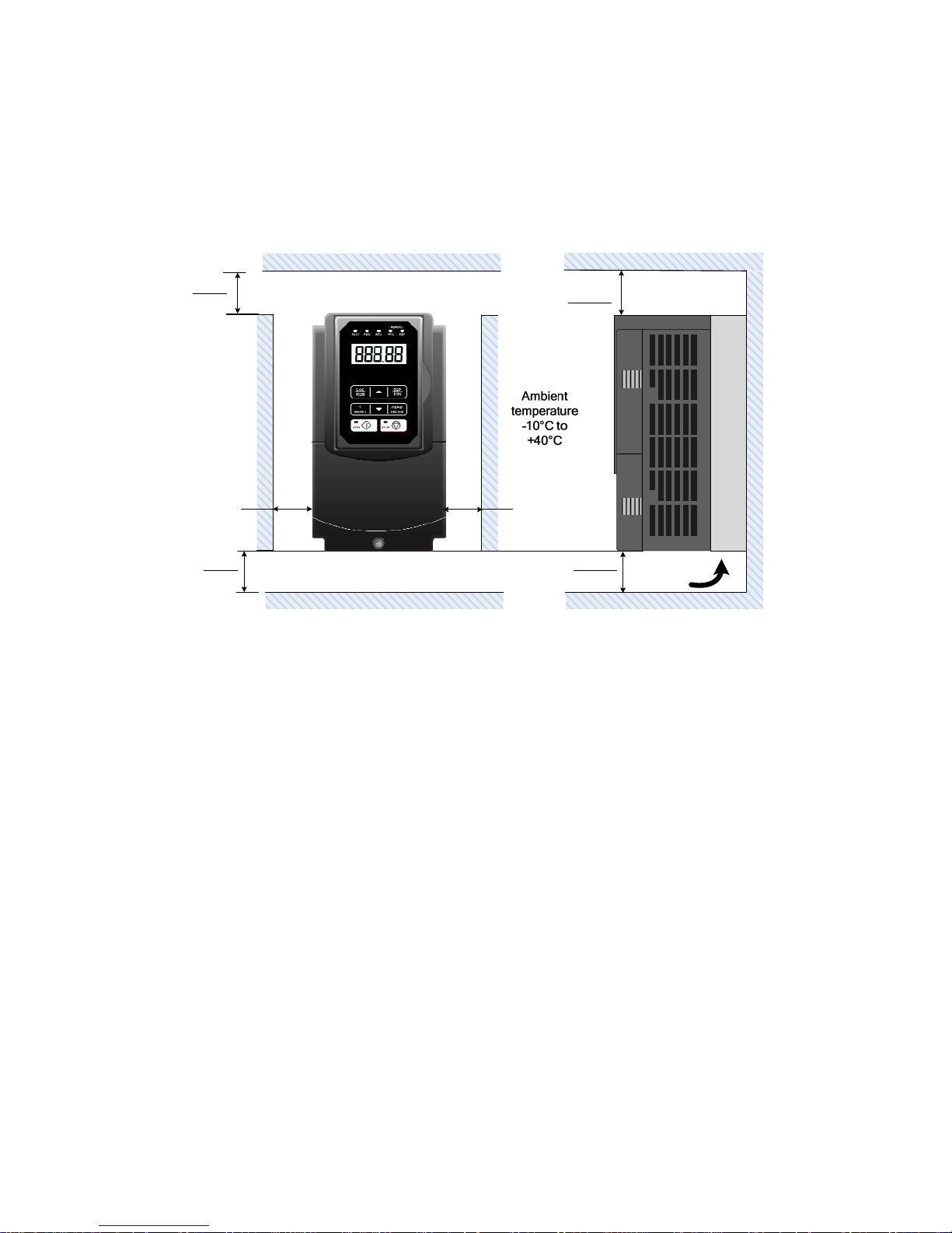
3.2.1 Installation Spaces
When installing the inverter, ensure that inverter is installed in upright position (vertical
direction) and there is adequate space around the unit to allow normal heat dissipation as per
the following Fig. 3.2.1
5.9in.
150mm
5.9in.
150mm
Air Flow
5.9in.
150mm
X
5.9in.
150mm
X
Fig 3.2.1: F510 Installation space
X = 1.18” (30mm) for inverter ratings up to 18.5kW
X = 1.96” (50mm) for inverter ratings 22kW or higher
Important Note: The inverter heatsink temperature can reach up to 90°C/ 194°F during
operation; make sure to use insulation material rated for this temperature.
Page 17
3-3
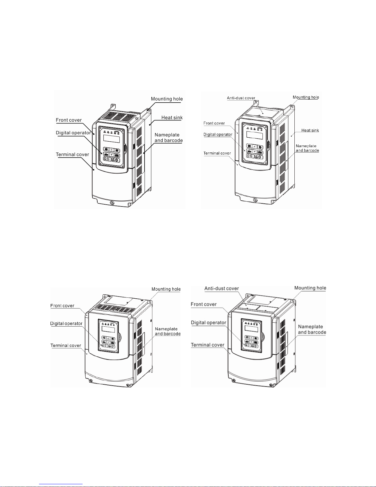
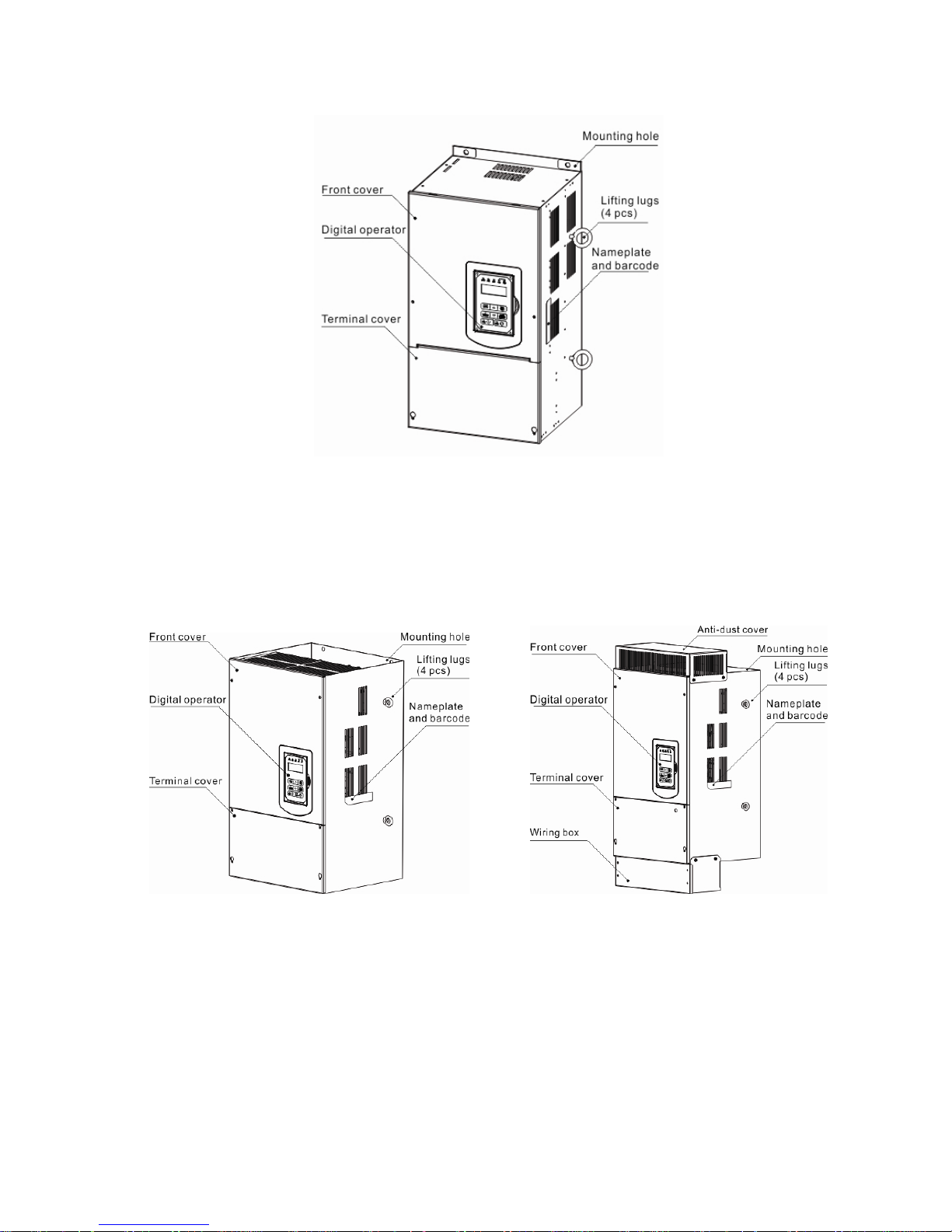
3.2.2 External View
3.2.2.1 External View (IP00/ IP20)
(a) 200V 5-7.5HP/ 400V 5-10HP
(Wall-mounted type, IEC IP00) (Wall-mounted type, IEC IP20, NEMA1)
(b) 200V 10-30HP/ 400V 15-40HP
(Wall-mounted type, IEC IP00) (Wall-mounted type, IEC IP20, NEMA1)
Page 18
3-4
(c) 200V 40-50HP/ 400V 50-75HP
(Wall-mounted type, IEC IP20, NEMA1)
(d) 200V 60-125HP/ 400V 100-250HP
(Wall-mounted type, IEC IP00) (Wall-mounted type, IEC IP20, NEMA1)
Page 19
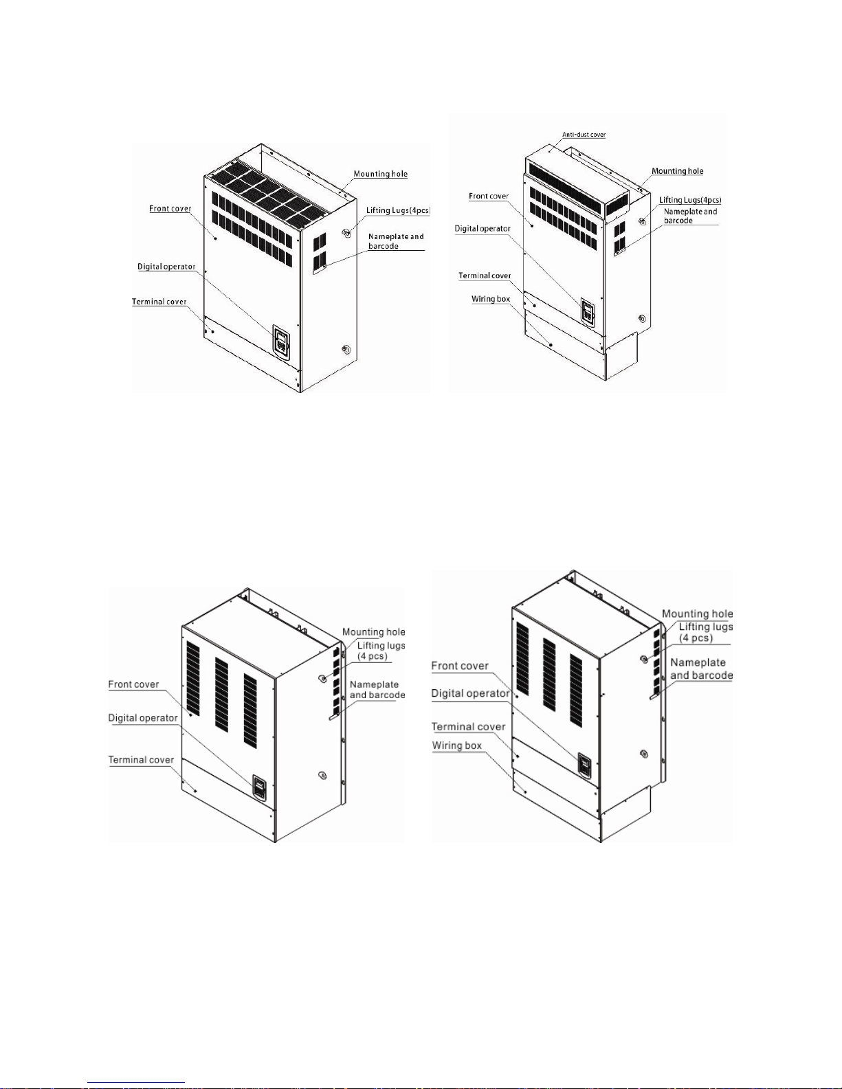
3-5
(e) 200V 150-175HP/ 400V 300-425HP
(Wall-mounted type, IEC IP00) (Wall-mounted type, IEC IP20)
(f) 400V 535-800HP
(Wall-mounted type, IEC IP00) (Wall-mounted type, IEC IP20)
Page 20
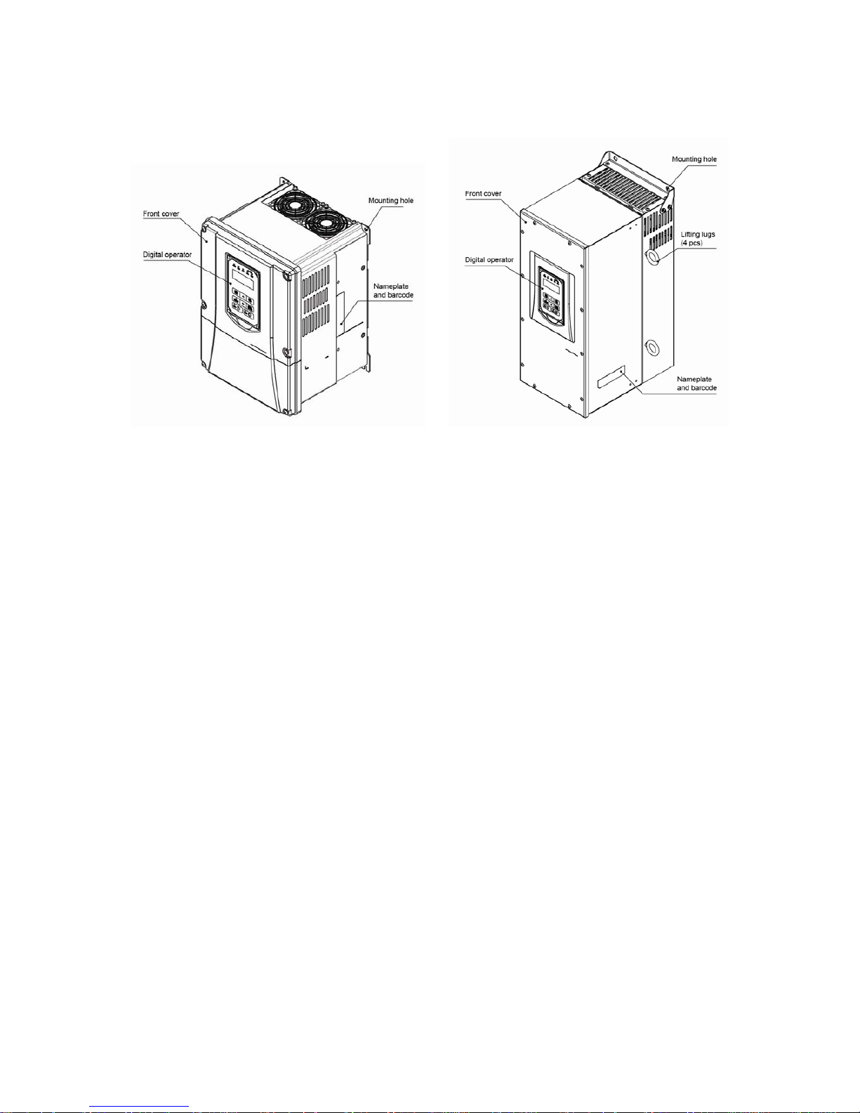
3-6
3.2.2.2 External View (IP55)
(a) 400V 5-25HP (b) 400V 30-100HP
(Wall-mounted type, IEC IP55) (Wall-mounted type, IEC IP55)
Page 21
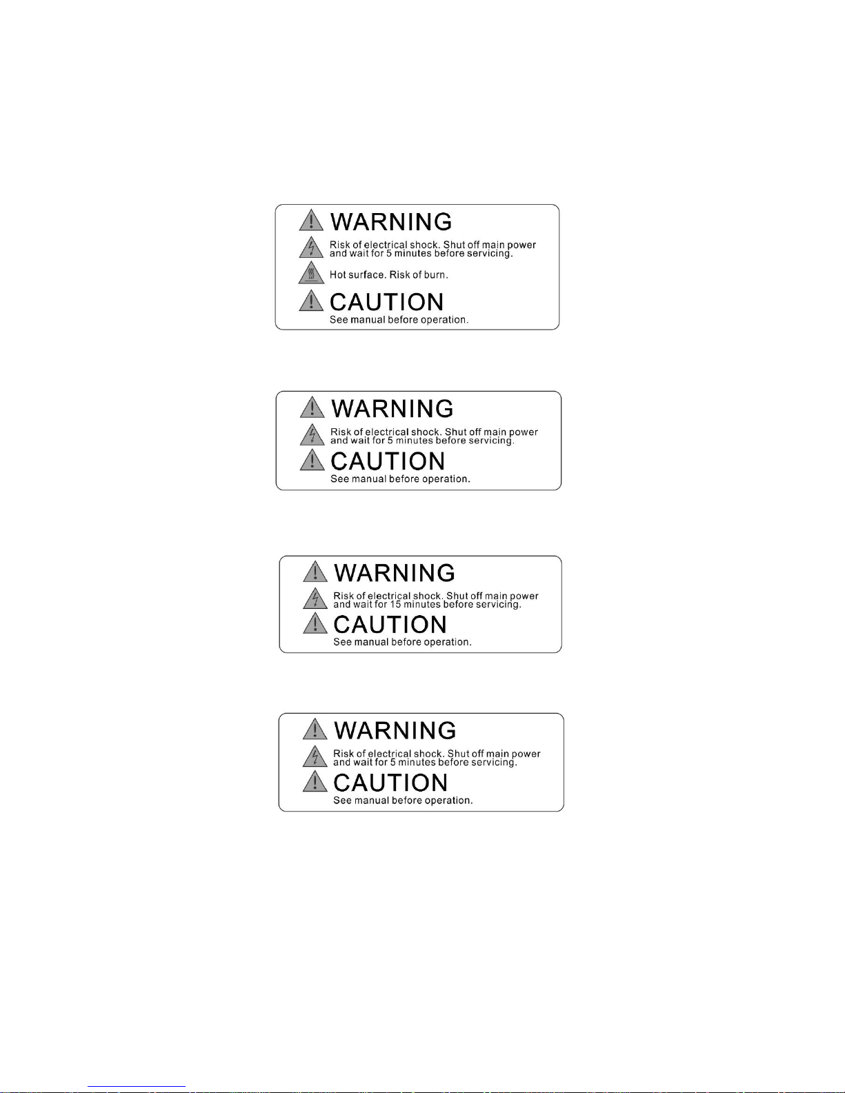
3-7
3.2.3 Warning Labels
Important:
Warning information located on the front cover must be read upon installation of
the inverter.
(a) 200V: 5-7.5HP/ 400V: 5-10HP (IP20)
(b) 200V: 10-15HP/ 400V: 15-20HP (IP20)
(c) 200V: 20-175HP/ 400V: 25-800HP(IP20)
(d) 400V:5-100HP (IP55)
Page 22

3-8
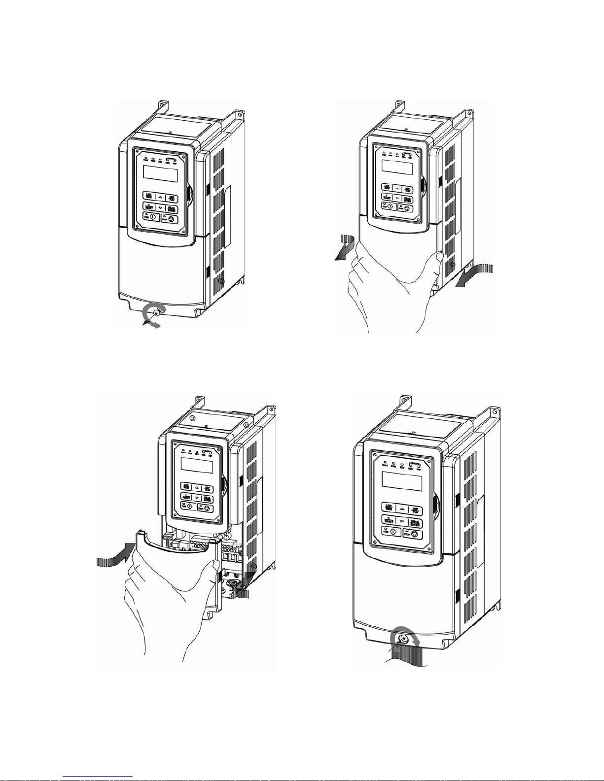
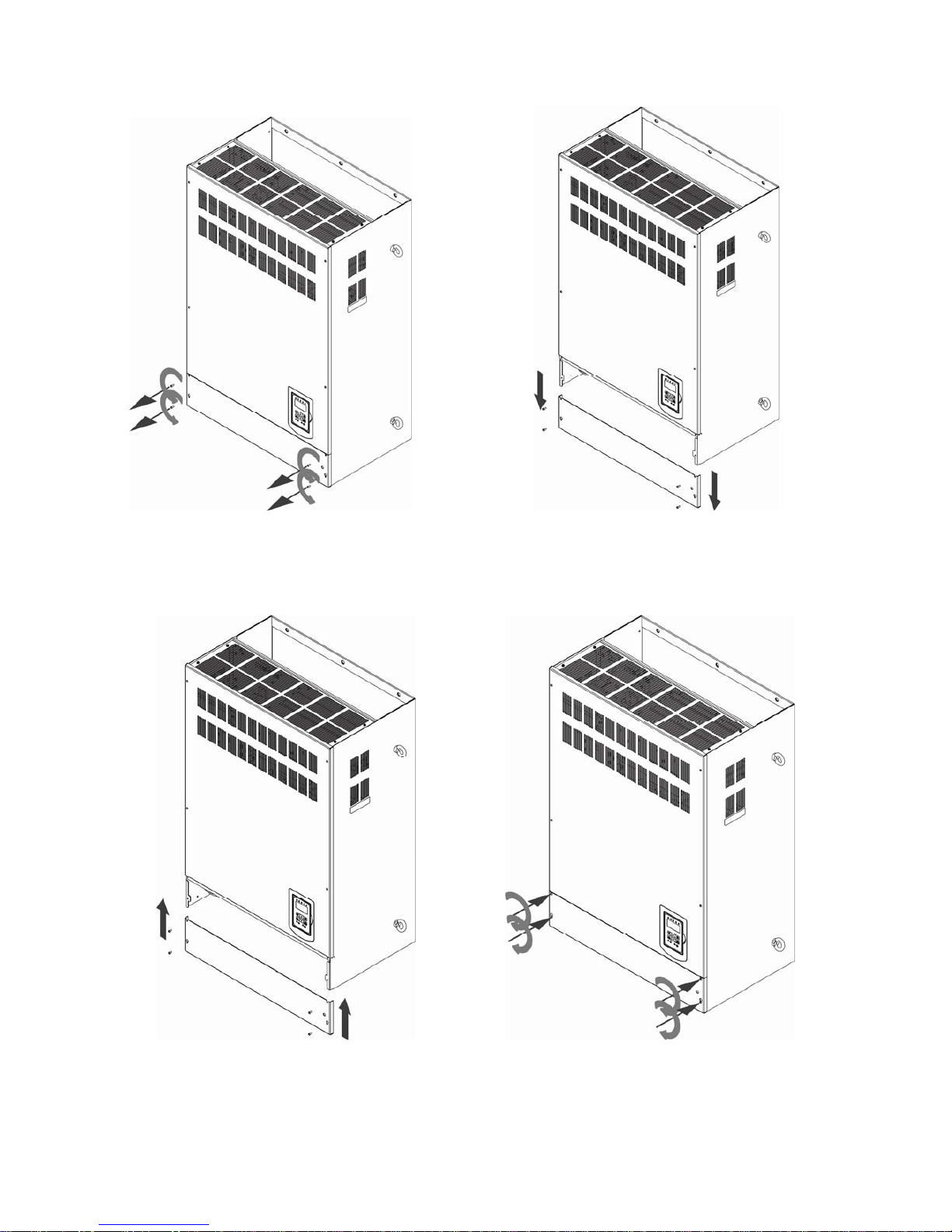
3.2.4 Removing the Front Cover and Keypad
Before making any wiring connections to the inverter, the front cover needs to be
removed.
IP00/ IP20 Type
Caution
• It is not required to remove the digital operator before making any wiring connections.
• Models 200V, 5 – 30 HP and 400V, 5 – 40 HP have a plastic cover. Loosen the screws
and remove the cover to gain access to the terminals and make wiring connections.
Place the plastic cover back and fasten screws when wiring connections have been
made.
• Models 200V, 40 - 175HP and 400V, 50 - 800HP have a metal cover. Loosen the
screws and remove the cover to gain access to the terminals and make wiring
connections. Place the metal cover back and fasten screws when wiring connections
have been made.
IP55 Type
Caution
• It is essential to remove the digital operator before making any wiring connections.
• Model 400V, 5 – 25 HP has a plastic cover. Loosen the screws and remove the cover to
gain access to the terminals and make wiring connections. Place the plastic cover back
and fasten screws when wiring connections have been made.
• Models 400V, 30 - 100HP has a metal cover. Loosen the screws and remove the cover
to gain access to the terminals and make wiring connections. Place the metal cover
back and fasten screws when wiring connections have been made.
Page 23
3-9
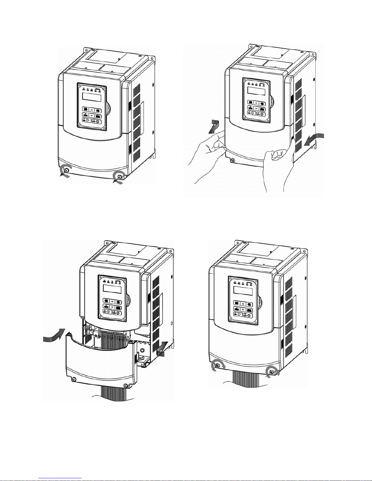
3.2.4.1 Standard Type (IP00/ IP20)
(a) 200V 5-7.5HP/ 400V 5-10HP
Step 1: Unscrew Step 2: Remove cover
Step 3: Make wire connections and place cover back Step 4: Fasten screw
Page 24
3-10
(b) 200V 10-30HP/ 400V 15-40HP
Step 1: Unscrew Step 2: Remove cover
Step 3: Make wire connections and place cover back Step 4: Fasten screw
Page 25
3-11
(c) 200V 40-50HP/ 400V 50-75HP
Step 1: Unscrew cover Step 2: Remove cover
Step 3: Make wire connections and place cover back Step 4: Fasten screw
Page 26
3-12
(d) 200V 60-125HP/ 400V 100-250HP
Step 1: Unscrew cover Step 2: Remove cover
Step 3: Make wire connections and place cover back Step 4: Fasten screw
Page 27
3-13
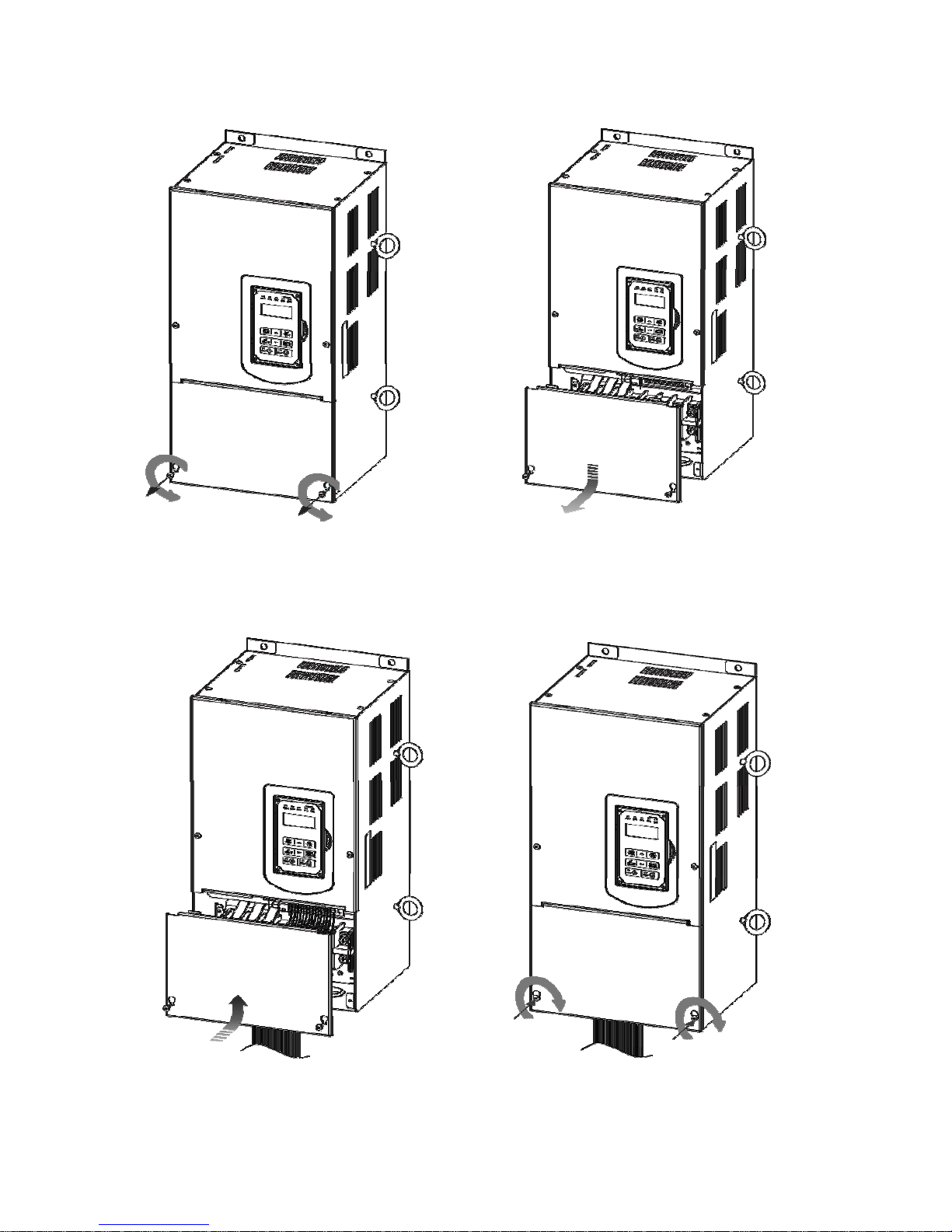
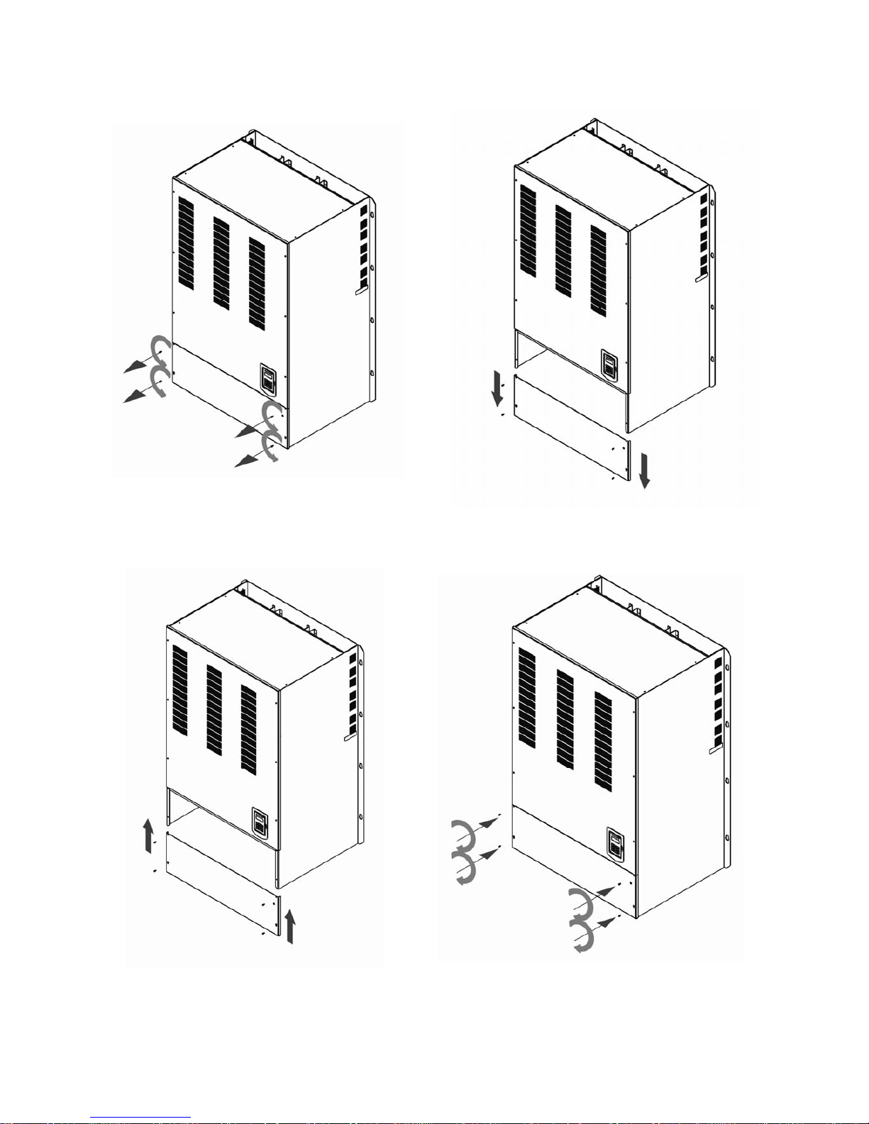
(e) 200V 150-175HP/ 400V 300-425HP
Step 1: Unscrew cover Step 2: Remove cover
Step 3: Make wire connections and place cover b Step 4: Fasten screw
Page 28
3-14
(f) 400V 535-800HP
Step 1: Unscrew cover Step 2: Remove cover
Step 3: Make wire connections and place cover back Step 4: Fasten screw
Page 29
3-15
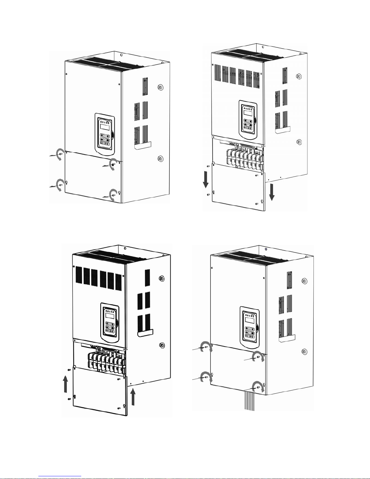
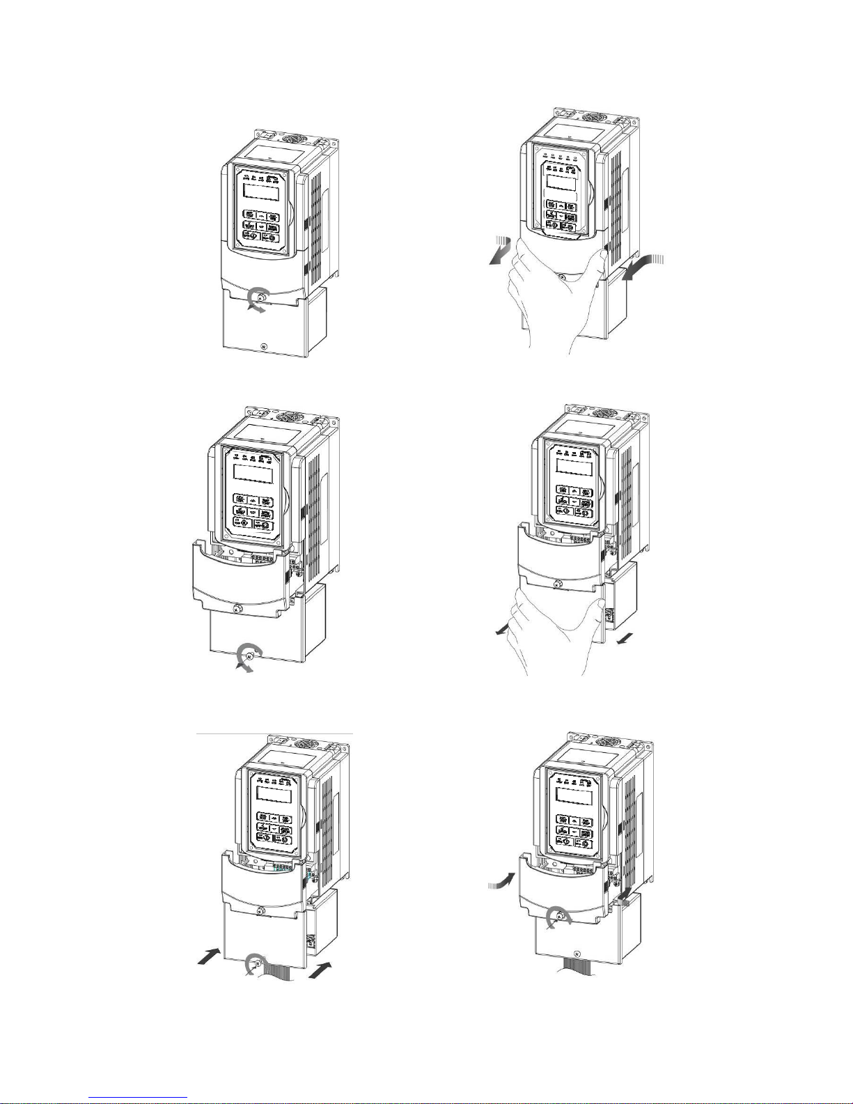
3.2.4.2 Built-in Filter Type (IP20/ IP00)
400V 5-75HP
Step 1: Unscrew cover Step 2: Remove cover
Step 3: Unscrew filter section Step 4: Remove filter cover
Step 5: Make connections and place filter cover back Step 6: Fasten screw
Page 30
3-16
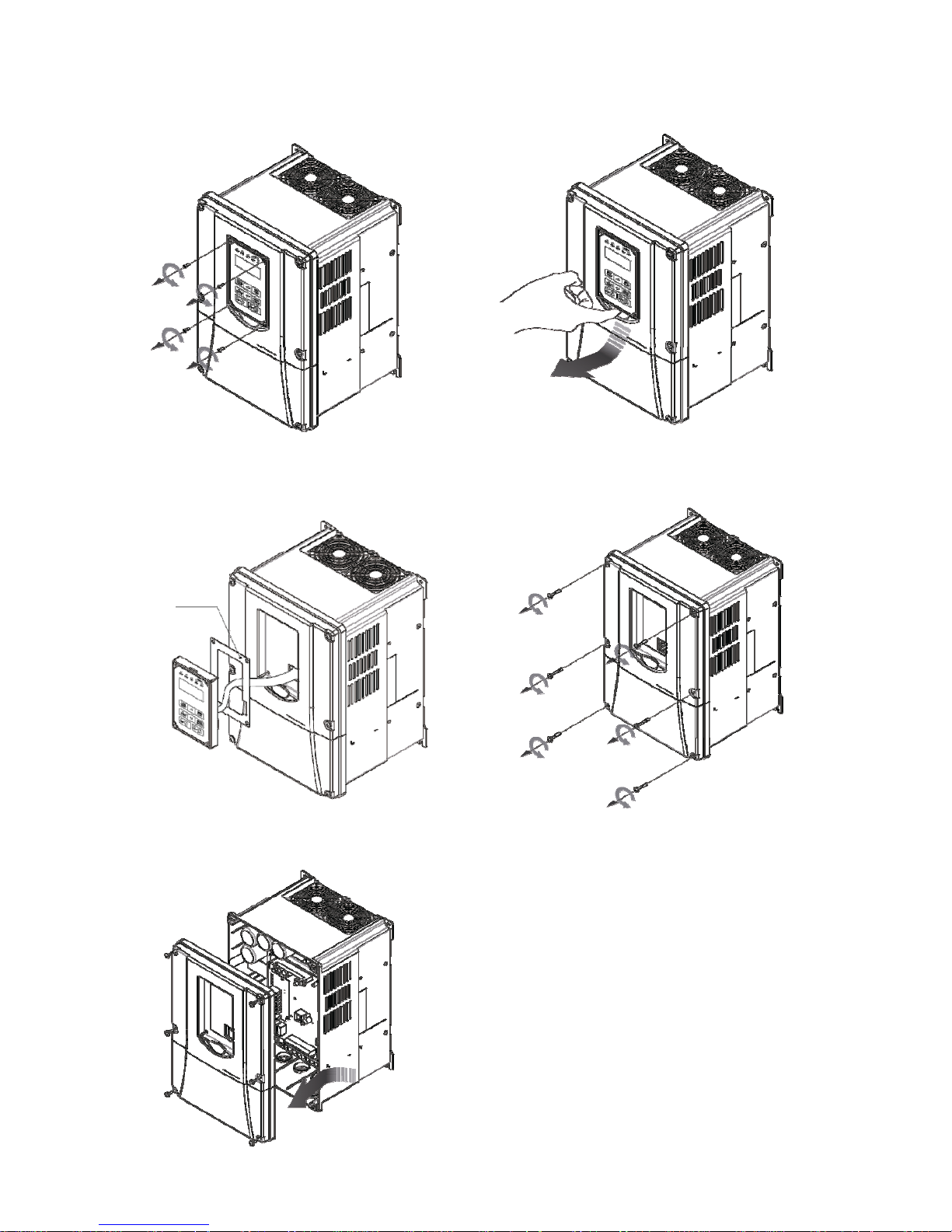
3.2.4.3 Built-in Filter Type (IP55)
(a) 400V 5-25HP
Step 1: Unscrew operator Step 2: Remove operator
Step 3: Pull out operator and remove power line Step 4: Unscrew cover
Step 5: Check the inside waterproof gasket is not pulled
away from cover while opening the cover
Waterproof gasket
Page 31

3-17
(b) 400V 30-100HP
Step 1: Unscrew operator Step 2: Remove operator
Step 3: Pull out operator and remove power line Step4: Unscrew cover and remove it
Waterproof gasket
Page 32

3-18
3.3 Inverter Wiring
3.3.1 Wire Gauges and Tightening Torque
To comply with UL standards, use UL approved copper wires (rated 75° C) and round crimp
terminals (UL Listed products) as shown in table below when connecting to the main circuit
terminals. Teco recommends using crimp terminals manufactured by NICHIFU Terminal Industry
Co., Ltd and the terminal crimping tool recommended by the manufacturer for crimping terminals
and the insulating sleeve.
Table 3.3.1.1 Wire gauges and tightening torque terminal screw size
Wire size
mm2 (AWG)
Terminal
Screw
size
Model of round
crimp terminal
Tightening torque
kgf.cm (in.lbs)
Model of
insulating
sleeve
Model of
crimp tool
M3.5 R1.25-3.5 8.2 to 10 (7.1 to 8.7) TIC 1.25 NH 1
0.75 (18)
M4 R1.25-4 12.2 to 14 (10.4 to 12.1) TIC 1.25 NH 1
M3.5 R1.25-3.5 8.2 to 10 (7.1 to 8.7) TIC 1.25 NH 1
1.25 (16)
M4 R1.25-4 12.2 to 14 (10.4 to 12.1) TIC 1.25 NH 1
M3.5 R2-3.5 8.2 to 10 (7.1 to 8.7) TIC 2 NH 1 / 9
M4 R2-4 12.2 to 14 (10.4 to 12.1) TIC 2 NH 1 / 9
M5 R2-5 22.1 to 24 (17.7 to 20.8) TIC 2 NH 1 / 9
2 (14)
M6 R2-6 25.5 to 30.0 (22.1 to 26.0) TIC 2 NH 1 / 9
M4 R5.5-4 12.2 to 14 (10.4 to 12.1) TIC 3.5/5.5 NH 1 / 9
M5 R5.5-5 20.4 to 24 (17.7 to 20.8) TIC 3.5/5.5 NH 1 / 9
M6 R5.5-6 25.5 to 30.0 (22.1 to 26.0) TIC 3.5/5.5 NH 1 / 9
3.5/5.5 (12/10)
M8 R5.5-8 61.2 to 66.0 (53.0 to 57.2) TIC 3.5/5.5 NH 1 / 9
M4 R8-4 12.2 to 14 (10.4 to 12.1) TIC 8 NOP 60
M5 R8-5 20.4 to 24 (17.7 to 20.8) TIC 8 NOP 60
M6 R8-6 25.5 to 30.0 (22.1 to 26.0) TIC 8 NOP 60
8 (8)
M8 R8-8 61.2 to 66.0 (53.0 to 57.2) TIC 8 NOP 60
M4 R14-4 12.2 to 14 (10.4 to 12.1) TIC 14 NH 1 / 9
M5 R14-5 20.4 to 24 (17.7 to 20.8) TIC 14 NH 1 / 9
M6 R14-6 25.5 to 30.0 (22.1 to 26.0) TIC 14 NH 1 / 9
14 (6)
M8 R14-8 61.2 to 66.0 (53.0 to 57.2) TIC 14 NH 1 / 9
M6 R22-6 25.5 to 30.0 (22.1 to 26.0) TIC 22 NOP 60/ 150H
22 (4)
M8 R22-8 61.2 to 66.0 (53.0 to 57.2) TIC 22 NOP 60/ 150H
M6 R38-6 25.5 to 30.0 (22.1 to 26.0) TIC 38 NOP 60/ 150H
30/38 (3 / 2)
M8 R38-8 61.2 to 66.0 (53.0 to 57.2) TIC 38 NOP 60/ 150H
M8 R60-8 61.2 to 66.0 (53.0 to 57.2) TIC 60 NOP 60/ 150H
50/ 60 (1/ 1/ 0)
M10 R60-10 102 to 120 (88.5 to 104) TIC 60 NOP 150H
M8 R70-8 61.2 to 66.0 (53.0 to 57.2) TIC 60 NOP 150H
70 (2/0)
M10 R70-10 102 to 120 (88.5 to 104) TIC 60 NOP 150H
M10 R80-10 102 to 120 (88.5 to 104) TIC 80 NOP 150H
80 (3/0)
M16 R80-16 255 to 280 (221 to 243) TIC 80 NOP 150H
M10 R100-10 102 to 120 (88.5 to 104) TIC 100 NOP 150H
M12 R100-12 143 to 157 (124 to 136) TIC 100 NOP 150H
100 (4/0)
M16 R80-16 255 to 280 (221 to 243) TIC 80 NOP 150H
Page 33

3-19
3.3.2 Wiring Peripheral Power Devices
Caution
z After power is shut off to the inverter, the capacitors will slowly discharge. Do NOT touch the
inverter circuitry or replace any components until the “CHARGE” indicator is off.
z Do NOT wire or connect/disconnect internal connectors of the inverter when the inverter is
powered up or when powered off and the “CHARGE”” indicator is on.
z Do NOT connect inverter output U, V and W to the supply power. This will result in damage to
the inverter.
z The inverter must be by properly grounded. Use terminal E to connect earth ground and
comply with local standards.
z It is required to disconnect the grounded wire in the control board when the inverter is not
grounded or floating ground power system.
z Do NOT perform a dielectric voltage withstand test (megger) on the inverter this will result in
inverter damage to the semiconductor components.
z Do NOT touch any of the components on the inverter control board to prevent damage to the
inverter by static electricity.
Caution
z Refer to the recommended wire size table for the appropriate wire to use. The voltage
between the power supply and the input of the inverter may not exceed 2%.
Phase-to-phase voltage drop (V) = 3 ×resistance of wire (Ω/km) × length of line m) × current×10-3.
(km=3280 x feet) / (m=3.28 x feet )
Reduce the carrier frequency (parameter 11-01) If the cable from the inverter to the motor is
greater than 25m (82ft). A high-frequency current can be generated by stray capacitance
between the cables and result in an overcurrent trip of the inverter, an increase in leakage
current, or an inaccurate current readout.
To protect peripheral equipment, install fast acting fuses on the input side of the inverter. Refer
to section 11.4 for additional information.
Page 34

3-20
Power Supply
M
C
C
B
Molded
Circuit
Breaker
Magnetic
Contactor
AC
Reactor
Fast
Acting
Fuse
Input Noise
Filter
F510
Inverter
Ground
Induction
Motor
Ground
Output Noise
Filter
Power supply:
z
Make sure the correct voltage is applied to avoid damaging the
inverter.
Molded-case circuit breaker (MCCB) or fused disconnect:
z A molded-case circuit breaker or fused disconnect must be installed
between the AC source and the inverter that conforms to the rated
voltage and current of the inverter to control the power and protect
the inverter.
z
Do not use the circuit breaker as the run/stop switch for the
inverter.
Ground fault detector / breaker:
z
Install a ground fault breaker to prevent problems caused by
current leakage and to protect personnel. Select current range up to
200mA, and action time up to 0.1 second to prevent high frequency
failure.
Magnetic contactor:
z Normal operations do not need a magnetic contactor. When
performing functions such as external control and auto restart after
power failure, or when using a brake controller, install a magnetic
contactor.
z
Do not use the magnetic contactor as the run/stop switch for
the inverter.
AC line reactor for power quality:
z When inverters are supplied by a high capacity power source (>
600KVA), an AC reactor can be connected to improve the power
factor.
Install Fast Acting Fuse:
z To protect peripheral equipment, install fast acting fuses in
accordance with the specifications in section 11.4 for peripheral
devices.
Input Noise filter:
z A filter must be installed when there are inductive loads affecting the
inverter. The inverter meets EN55011 Class A, category C3 when
the TECO special filter is used. See section 11.3 for peripheral
devices.
Inverter:
z Output terminals T1, T2, and T3 are connected to U, V, and W
terminals of the motor. If the motor runs in reverse while the inverter
is set to run forward, swap any two terminals connections for T1, T2,
and T3.
z
To avoid damaging the inverter, do not connect the output
terminals T1, T2, and T3 to AC input power.
z Connect the ground terminal properly. (200V series: Rg <100Ω;
400V series: Rg <10Ω.)
Output Noise filter:
z An output noise filter may reduce system interference and induced
noise.
Motor:
z If the inverter drives multiple motors the output rated current of the
inverter must be greater than the total current of all the motors.
Page 35

3-21
3.3.3 General Wiring Diagram
The following is the standard wiring diagram for the F510 inverter (◎ indicates main circuit
terminals and ○ indicates control circuit terminals ). Locations and symbols of the wiring terminal
block might be different due to different models of F510. The description of control circuit terminals
and main circuit terminals can be referred to Table 3.3.5.1, 3.3.6.1 and 3.3.6.2
Page 36

3-22
3.3.4 Single/ Multi- Pump Dedicated Wiring Diagram
PUMP Wiring Diagram for Pressure Sensor of Voltage Type
Single Pump:
Multi-Pump:
S(+) S( - ) S1 S3 S5 AI2
E24VGS2S4S6F1F2POP I
24V +10V MTGNDGNDAI1
AO2 E
R1A R1B R1 C R2A R2C R3A R3C
AO1
S(+) S( - ) S1 S3 S5 AI2
E24VGS2S4S6F1F2POP I
24V +10V MTGNDGNDAI1
AO2 E
R1A R1B R1 C R2A R2C R3A R3C
AO1
F510 Single Pump Operation
Operation Switch
Pressure
Converter
TM2
SW2
SW3
NPN
J
P
1
J
P
2
V
I
S(+)
S(-) S1 S3 S5 AI2
E24VGS2S4S6 F1F2POP I
24V +10V MT GND GND
AI1
AO2 E
R1A R1B R1C R2A R2C R3A R3C
AO1
00-02 = 1 (Control Circuit Terminal); 00-05 = 5 (PID)
04-00 = 0 (0~10V); 10-00=0 (Target Source: Keypad)
10-01 = 2 (Feedback Source: AI2)
10-03 = XXX1b( PID is enabled)
23-00 = 1 (Pump); 23-01 = 0 (Single Pump)
-
+
Page 37

3-23
PUMP Wiring Diagram for Pressure Sensor of Current Type
Single Pump:
Multi-Pump:
Notes: 1. The position of dip switch requires being correct (SW2, SW3).
2. It is required to reconnect after setting Master/ Slave.
Page 38

3-24
3. 24VG and GND require short circuit.
4. When the communication modes is selected to be multiple pumps in parallel connection
(09-01=3), the baud rate settings (09-02) of Master and Slave are required to be consistent.
Refer to parameter 23-31 for the actions in parallel connection modes.
5. In the wiring of multi-pump current type pressure sensor, it is required to adjust Slave to
be 04-07(AI2 Gain) =252.0% and 04-08(AI1 Bias) =25.0%.
Page 39

3-25
3.3.5 Wiring for Control Circuit Terminals
Control circuit terminals identification
IP20 type
z 200V: 5HP~50HP,400V: 5HP~75HP
AI2S(+) S(-) S1 S3 S5 24V +10V MT GND GND AI1
AO1 AO2 E
R1A R1B R1C
E 24VG S2 S4 S6 F1 F2 PO P I
R2AR2CR3AR3C
z 200V: 60HP~125HP,400V: 100HP~800HP
S(+) S(-) S1 S3 S5 AI2
E 24VG S2 S4 S6 F1 F2 PO P I
24V +10V MT GND GND AI1
AO2 E
R1A R1B R1C R2A R2C R3A R3C
AO1
IP55 type
z 400V: 5HP~100HP
AI2S(+) S(-) S1 S3 S5 24V +10V MT GND GND AI1
AO1 AO2 E
R1A R1B R1C
E 24VG S2 S4 S6 F1 F2 PO P I
R2AR2CR3AR3C
Page 40

3-26
Table 3.3.5.1 Description of control circuit terminals
Type Terminal Terminal function Signal level/ information
S1
2-wire forward rotation/ stop command (default), multi-
function input terminals * 1
S2
2-wire reversal rotation/ stop command (default), multi-
function input terminals * 1
S3
Multi-speed/ position setting command 1 (default), multi-
function input terminals * 1
S4
Multi-speed/ position setting command 2 (default), multi-
function input terminals * 1
S5
Multi-speed/ position setting command 3 (default), multi-
function input terminal* 1
Digital
input
signal
S6 Fault reset (default), multi-function input terminal * 1
Signal Level 24 VDC
(opto-isolated)
Maximum current: 8mA
Maximum voltage: 30 Vdc
Input impedance: 4.22k
24V Digital signal SOURCE point (SW3 switched to SOURCE )
24V
Power
supply
24VG
Common terminal of Digital signals
Common point of digital signal SINK ( SW3 switched to
SINK )
±15%,
Max. output current: 250mA
(The sum of all loads
connected)
+10V Power for external speed potentiometer
±5%
(Max. current: 20mA )
MT Motor temperature detector of externally connecting PTC
1330 movement,
550 return
AI1 Multi-function analog input for speed reference (0-10V input)
From 0 to +10V
Input impedance: 20K
Resolution: 12bit
AI2
Multi-function analog input terminals *2, can use SW2 to
switch voltage or current input
(0~10V)/(4-20mA)
From 0 to +10V
Input impedance: 20K
From 4 to 20 mA
Input impedance: 250
Resolution: 12bit
GND Analog signal ground terminal
-
---
Analog
input
signal
E Shielding wire’s connecting terminal (Ground)
-
---
AO1
Multi-function analog output terminals *3 (0~10V/ 4-20mA
output)
AO2
Multi-function analog output terminals *3 (0~10V/ 4-20mA
output)
Analog
output
signal
GND Analog signals ground terminal
From 0 to 10V
Max. current: 2mA
From 4 to 20 mA
PO Pulse output, Band width 32KHz
Max. Frequency: 32KHz
Open Collector output
Load: 2.2 K
Pulse
output
signal
GND Analog signals ground terminal
-
---
PI Pulse command input, frequency width of 32KHz
L: from 0.0 to 0.5V
H: from 4.0 to 13.2V
Max. Frequency: 0 - 32KHz
Impedance: 3.89 K
Pulse
input
signal
GND Analog signals ground terminal
-
---
Page 41

3-27
Table 3.3.5.1 Description of control circuit terminals (Continued)
Type Terminal Terminal function Signal level/ information
R1AR1B-
R1C
Relay A contact (multi-function output terminal)
Relay B contact (multi-function output terminal)
Relay contact common terminal, please refer to
parameter group 03 in this manual for more functional
descriptions.
Rating:
250Vac: 10 mA ~ 1A
30Vdc: 10 mA ~ 1A
R2A-R2C With the same functions as R1A/R1B/R1C
Relay
output
R3A-R3C With the same functions as R1A/R1B/R1C
Rating:
250Vac: 10 mA ~ 1A
30Vdc: 10 mA ~ 1A
F1
On: normal operation.
Off: emergency stop.
(Jumper wired has to be removed to use external safety
function to stop.)
24Vdc, 8mA, pull-high
Safety
input
F2 Safety command common terminal 24V Ground
S (+)
RS-485
port
S (-)
RS485/MODBUS differential input and output
Grounding
E (G)
Grounding to earth
Shield the connecting terminal
----
Notes:
*1: Multi-function digital input can be referred to in this manual.
- Group 03: External Terminals Digital Input / Output Function Group.
*2: Multi-function analog input can be referred to in this manual.
- Group 04 - External Terminal Analog Signal Input (Output) Function Group.
*3: Multi-function analog output can be referred to in this manual.
- Group 04 - External Terminal Analog Signal Input (Output) Function Group.
Caution
Maximum output current capacity for terminal 10V is 20mA.
Multi-function analog output AO1 and AO2 are for use for an analog output meter. Do not
use these output for feedback control.
Control board’s 24V and 10V are to be used for internal control only. Do not use the
internal power-supply to power external devices.
Page 42

3-28
3.3.6 Wiring for Main Circuit Terminals
Table 3.3.6.1 Description of main circuit terminals (IP00/IP20 Type)
Terminal
200V:5~30HP
400V:5~40HP
200V: 40~175HP
400V: 50~800HP
R/L1
S/L2
T/L3
Input Power Supply
B1/P
B2
-
\
• B1/P-\:DC power supply
• B1/P-B2:external braking
resistor
⊕
-
• ⊕ -\:DC power supply
or connect braking module
U/T1
V/T2
W/T3
Inverter output
E
Ground terminal
Table 3.3.6.2 Description of main circuit terminals (IP55 Type)
400V
Terminal
5 - 100HP
R/L1,S/L2, T/L3 Input Power Supply
U/T1,V/T2, W/T3 Inverter output
B1, B2 Braking resistor connecting terminal
*1
♁1, ♁2 DC reactor connecting terminal
*2
B1, B2, \
DC power supply (DC+, DC-)
Braking module connecting terminal
( PE)
Ground terminal
*1. The model of 400V 25HP (18.5KW) or below is built-in braking transistor.
*2. Before connecting DC reactor, please remove short circuit between terminal ♁1 and ♁2.
Page 43

3-29
Main circuit terminals identification and screw size
IP20 Type
․200V: 5-7.5HP/ 400V: 5-10HP
Terminal screw size
T
M4 M4
․
200V: 10-15HP/ 400V: 15- 20HP
Terminal screw size
T
M4 M4
․200V: 20-30HP/ 400V: 25-40HP
Terminal screw size
T
M6 M6
․
200V: 40-50HP/ 400V: 50-75HP
Terminal screw size
T
M8 M8
T
T
T
T
Page 44

3-30
․200V: 60-75HP/ 400V: 100-125HP
Terminal screw size
Power supply
T
400V 100HP M8 M10
200V 60-75HP/
400V 125HP
M10 M10
․200V: 100-125HP/ 400V: 150-250HP
Terminal screw size
T
M10 M10
․200V: 150-175HP/ 400V: 300-425HP
Terminal screw size
T
M12 M10
․400V: 530-800HP
Terminal screw size
T
M10 M10
T
Page 45

3-31
IP55 Type
․400V: 5-7.5HP
Terminal screw size
T
M4 M4
․400V: 10-15HP
Terminal screw size
T
M4 M4
․400V: 20-25HP
Terminal screw size
T
M6 M6
․400V: 30-50HP
Terminal screw size
T1
M6 M6
Page 46

3-32
․400V: 60-75HP
Terminal screw size
T1
M8 M8
․
400V : 100HP
Terminal screw size
T1 T2
M8 M10 M8
Page 47

3-33
Input / Output Power Section Block Diagram
The following diagrams show the basic configuration of the power sections for the range of
horsepower and input voltages. This is shown for reference only and is not a detailed depiction.
IP00/IP20 Type
1. IP20 200V: 5~30HP 400V: 5~40HP
2. IP20 200V: 40~50HP 400V: 50~75HP
3. IP20 200V: 60~75HP 400V: 100~125HP 4. IP20 200V: 100~125HP
5. IP20 400V: 150~250HP
6. IP20 200V: 150~175HP
E
○
─
CONTROL
CIRCUITS
R/L1
S/L2
T/L3
U/T1
V/T2
W
/T3
B1/P
SPS
B2
E
○
─
CONTROL
CIRCUITS
R/L1
S/L2
T/L3
U/T1
V/T2
W
/T3
○
┼
SPS
E
N
P
DCL
SPS C/B
AC/DC
R/L1
S/L2
T/L3
U/T1
V/T2
W/T3
U/T1
V/T2
W
/T3
SPS
N
P
DCL
C/B
SPS
E
S/L2
T/L3
R/L1
E
N
P
DCL
SPS
C/B
AC/DC
R/L1
S/L2
T/L3
U/T1
V/T2
W/T3
E
N
P
DCL
SPS
C/B
AC/DC
W/T3
R/L1
T/L3
S/L2
U/T1
V/T2
Page 48

3-34
7. IP20 400V: 300~425HP
8. IP20 400V: 535~800HP
IP55 Type
1. IP55 400V: 5~15HP
2. IP55 400V: 20~25HP
3. IP55 400V: 30~100HP
E
○
─
C/B
R/L1
S/L2
T/L3
U/T1
V/T2
W
/T3
B1
SPS
B2
○┼1
○
┼
2
DCL
Filter
E
○
─
C/B
R/L1
S/L2
T/L3
U/T1
V/T2
W
/T3
B1
SPS
B2
○┼1
○
┼
2
DCL
Filter
E
○
─
C/B
R/L1
S/L2
T/L3
U/T1
V/T2
W
/T3
SPS
○┼1
○
┼
2
DCL
Filter
E
N
P
DCL
SPS
C/B
AC/DC
W/T3
R/L1
T/L3
S/L2
U/T1
V/T2
E
N
W/T3
R/L1
T/L3
S/L2
U/T1
V/T2
SPS
C/B
AC/DC
P
Page 49

3-35
Cooling Fan Supply Voltage Selection (400V class)
The inverter input voltage range of the F510 400V class models ranges from 380 to 460Vac. In
these models the cooling fan is directly powered from the power supply. Inverter models F510-
4125/ 4150/ 4175/ 4215/ 4250/ 4300/ 4375/ 4425/ 4535/ 4670/ 4800-H3 requires the user to select
the correct jumper position based on the inverter input voltage ("440V" is the default position for
these models). Please select the correct position according to the input voltage. If the voltage
setting is too low, the cooling fan will not provide adequate cooling for the inverter resulting in an
over-heat error. If the input voltage is greater than 460Vac, select the “460V” position.
(1) 400V: 150HP~250HP
(2) 400V:300HP~800HP
4KA69X613W01
DM1
25CN
36CN
32CN
31CN
33CN
34CN
35CN
FU1
220V
440V
S
R
TB3 1
+
220V
26CN
440V
TB4(220V)
380V1400/4151440V1460V
1
SA4(220V)
2
TB2
JP1 JP2 JP3 JP4
4KA69X571W01
4P108C0010103 VER.04
DM1 25CN
36CN
32CN
31CN
33CN
34CN
35CN
2
FU1
220V
440V
S
R
TB3
1
+
220V
26CN
440V
TB4(220V)
380V1400/4151440V1460V
1
SA4(220V)
JP1 JP2 JP3 JP4
Page 50

3-36
Power Input Wire Size, NFB and MCB Part Numbers
The following table shows the recommended wire size, molded case circuit breakers and magnetic
contactors for each of the F510 models. It depends on the application whether or not to install a
circuit breaker. The NFB must be installed between the input power supply and the inverter input
(R/L1, S/L2, T/L3).
Note: When using a ground protection, make sure the current setting is above 200mA and trip delay
time is 0.1 sec of higher.
Table 3.3.6.3 Wiring Instrument for 200V/400V class (IP00/IP20 type)
F510 Model Wire size (mm2)
Power
supply
Horse power
(HP)
Rated
KVA
Rated
current (A)
Main
circuit
*1
Grounding
E(G)
Control
line*2
NFB*3 MC*3
5HP 5.5 14.5
3.5~5.5 3.5~5.5 0.5~2
TO-50EC(30A) CU-16
7.5HP 8.0 22 5.5 5.5
0.5~2
TO-50EC(30A) CU-16
10HP 11.4 30 8
5.5~8 0.5~2
TO-100S(50A) CU-18
15HP 15 42 8
5.5~8 0.5~2
TO-100S(50A) CU-25
20HP 21 56 14 8
0.5~2
TO-100S(100A) CU-50
25HP 26 69 22 8
0.5~2
TO-100S(100A) CU-65
30HP 30 79 22 14
0.5~2
TO-225S(100A) CU-80
40HP 42 110 38 14
0.5~2
TO-225S(150A) CN-100
50HP 53 138 60 22
0.5~2
TO-225S(175A) CN-125
60HP 64 169 80 22
0.5~2
TO-225S(200A) CN-150
75HP 76 200 100 22
0.5~2
TO-225S(225A) CN-180
100HP 95 250 150 22
0.5~2
TO-400S(300A) CN-300
125HP 119 312 200 38
0.5~2
TO-400S(400A) CN-300
150HP 137 400 300 38
0.5~2
TO-600S(600A) S-K400
200V
3 Ø
175HP 172 450 250*2P 50
0.5~2
TO-800S(800A) S-K600
5HP 7.0 9.2
2~5.5 3.5~5.5 0.5~2
TO-50EC(15A) CU-18
7.5HP 8.5 12.1
2~5.5 3.5~5.5 0.5~2
TO-50EC(15A) CU-18
10HP 13.3 17.5
3~5.5 3.5~5.5 0.5~2
TO-50EC(20A) CU-18
15HP 18 23 5.5 5.5
0.5~2
TO-50EC(30A) CU-25
20HP 24 31 8 8
0.5~2
TO-100S(50A) CU-25
25HP 29 38 8 8
0.5~2
TO-100S(50A) CU-35
30HP 34 44 8 8
0.5~2
TO-100S(50A) CU-50
40HP 41 54 14 8
0.5~2
TO-100S(75A) CU-50
50HP 55 73 22 8
0.5~2
TO-100S(100A) CU-65
60HP 67 88 22 14
0.5~2
TO-100S(100A) CN-80
75HP 79 103 38 14
0.5~2
TO-225S(150A) CN-100
100HP 111 145 60 22
0.5~2
TO-225S(175A) CN-150
125HP 126 168 80 22
0.5~2
TO-225S(225A) CN-150
150HP 159 208 150 22
0.5~2
TO-400S(300A) CN-300
175HP 191 250 150 22
0.5~2
TO-400S(300A) CN-300
215HP 226 296 200 30
0.5~2
TO-400S(400A) CN-300
250HP 250 328 250 30
0.5~2
TO-400S(400A) S-K400
300HP 332 435 300 38
0.5~2
TO-600S(600A) S-K600
375HP 393 515 250*2P 50
0.5~2
TO-800S(800A) S-K600
425HP 457 585 250*2P 50
0.5~2
TE-1000(1000A) S-K600
535HP 526 700 300*2P 50
0.5~2
1000 800
670HP 640 875 300*2P 50
0.5~2
1200 1000
400V
3 Ø
800HP 732 960 300*2P 50
0.5~2
1200 1000
Page 51

3-37
*1. The main circuit terminals: R/L1, S/L2, T/L3 , U/T1, V/T2, W/T3, B1/P, B 2 , \, ⊕.
*2. Control line is the terminal wire on the control board.
*3. The NFB and MCB listed in the table are of TECO product numbers, products with same rated
specification of other brands may be used. To reduce electrical noise interference, ensure that a RC
surge absorber (R: 10/ 5W, C: 0.1f/1000VDC) is added to both sides of MCB coil.
Table 3.3.6.4 Wiring Instrument for 400V class (IP55 type)
F510 Model Wire size(mm2)
Power
supply
Horse
power
(HP)
Rated
KVA
Rated
current
(A)
Main
circuit
*1
Grounding
E(G)
Control
line*2
NFB*3 MC*3
5HP 7.0 9.2
2~5.5 3.5~5.5 0.5~2
TO-50EC(15A) CU-18
7.5HP 8.5 12.1
2~5.5 3.5~5.5 0.5~2
TO-50EC(15A) CU-18
10HP 13.3 17.5
3~5.5 3.5~5.5 0.5~2
TO-50EC(20A) CU-18
15HP 18 23 5.5 5.5
0.5~2
TO-50EC(30A) CU-25
20HP 24 31 8 8
0.5~2
TO-100S(50A) CU-25
25HP 29 38 8 8
0.5~2
TO-100S(50A) CU-35
30HP 34 44 8 8
0.5~2
TO-100S(50A) CU-50
40HP 41 54 14 8
0.5~2
TO-100S(75A) CU-50
50HP 55 73 22 8
0.5~2
TO-100S(100A) CU-65
60HP 67 88 22 14
0.5~2
TO-100S(100A) CN-80
75HP 79 103 38 14
0.5~2
TO-225S(150A) CN-100
400V
3 Ø
100HP 111 145 60 22
0.5~2
TO-225S(175A) CN-150
*1. The main circuit terminals: R(L1), S(L2), T(L3), \, ♁1, ♁2, U(T1), V(T2), W(T3),B1, B2 (Polyethylene
power line of 600V is recommended to be used.)
*2. Control line is the terminal wire on the control board.
*3. The NFB and MCB listed in the table are of TECO product numbers, products with same rated
specification of other brands may be used. To reduce electrical noise interference, ensure that a RC
surge absorber (R: 10/ 5W, C: 0.1f/1000VDC) is added to both sides of MCB coil.
Page 52

3-38
3.3.7 Wiring Precautions
!
• Do NOT remove any protective covers or attempt any wiring while input power is
applied. Connect all wiring before applying input power. When making wiring
changes after power up, remove input power and wait a minimum of five
minutes after power has been turned off before starting. Also confirm that the
charge lamp is off and that DC voltage between terminals B1/P or (+) and (-)
does not exceed 25V, otherwise electric shock may result.
• Only authorized personnel should work on the equipment. (Take off metal
jewelry such as watches and rings and use insulated tools.), otherwise electric
shock or injury may result.
(A) Wiring for control circuit:
(1) Separate the wiring for control circuit terminals from main circuit wiring for terminals
(R/L1,
S/L2, T/L3, U/T1, V/T2, and W/T3).
(2) Separate the wiring for control circuit terminals (R1A, R1B, R1C / R2A, R2C /R3A, R3C)
from wiring for terminals S1~S6, A01, A02, GND, +10V-, AI1, AI2, and GND wiring.
(3) Use shielded twisted-pair cables (#24 - #14 AWG / 0.5 -2 mm
2
) shown in Fig. 3.3.7.1 for
control circuits to minimize noise problems. The maximum wiring distance should not
exceed 50m (165 ft).
Figure 3.3.7.1 Shielded Twisted-Pair
(B) Wiring for main circuit:
(1) The Input power supply voltage can be connected in any phase sequence to power input
terminals R/L1, S/L2, or T/L3 on the terminal block.
(2) DO NOT connect the AC input power source to the output terminals U/T1, V/T2 and. W/T3.
(3) Connect the output terminals U/T1, V/T2, W/T3 to motor lead wires U/T1, V/T2, and W/T3,
respectively.
(4) Check that the motor rotates forward with the forward run source. If it does not, swap any 2
of the output cables to change motor direction.
(5) DO NOT connect phase correcting capacitors or LC/RC noise filter to the output circuit.
Page 53

3-39
(C) Grounding:
(1) Connect the ground terminal (E) to ground having a resistance of less than 100.
(2) Do not share the ground wire with other devices, such as welding machines or power tools.
(3) Always use a ground wire that complies with the local codes and standards for electrical
equipment and minimize the length of ground wire.
(4) When using more than one inverter, be careful not to loop the ground wire, as shown below
in Fig. 3.3.7.2.
Figure 3.3.7.2 F510 Inverter Grounding
Page 54

3-40
3.3.8 Input Power and Cable Length
Cable size
The length of the cables between the input power source and /or the motor and inverter can
cause a significant phase to phase voltage reduction due to the voltage drop across the cables.
The wire size shown in Tables 3.3.6.3 & 3.3.6.4 is based on a maximum voltage drop of 2%. If this
value is exceeded, a wire size having larger diameter may be needed. To calculate phase tot
phase voltage drop, apply the following formula:
Phase-to-phase voltage drop (V) = 3 ×resistance of wire (Ω/km) × length of line m) × current×10-3.
(km=3280 x feet)
(m=3.28 x feet)
Cable length vs. Carrier frequency
The allowable setting of the PWM carrier frequency is also determined by motor cable length
and is specified in the following Table 3.3.8.1.
Table 3.3.8.1 Cable Length vs. Carrier Frequency
Cable length between
the inverter and
Motor in m (ft.).
< 30
(100)
30 – 50
(100 – 165)
50 – 100
(166 - 328)
>
100
(329)
Recommended carrier
frequency allowed
Parameter 11-01
16kHz
(max)
10 kHz
(max)
5 kHz
(max)
2 kHz
(max)
Installing an AC line reactor
If the inverter is connected to a large-capacity power source (600kVA or more), install an
optional AC reactor on the input side of the inverter. This also improves the power factor on the
power supply side.
Page 55

3-41
3.4 Inverter Specifications
Basic Specifications
(a) 200V class
(b) 400V class
Inverter capacity (HP)
425 535 670 800
Rated Output Capacity (KVA)
445 525 640 731
Rated Output Current (A)
585 700 875 960
Maximum Applicable Motor
*1
HP (KW)
425
(315)
535
(400)
670
(500)
800
(600)
Maximum Output Voltage (V)
3-phase 380V~480V
Output Rated
Maximum Output Frequency
(Hz)
Based on parameter setting 0.1~400.0 Hz
Rated Voltage, Frequency
3-phase 380V ~ 480V, 50/60Hz
Allowable Voltage Fluctuation
-15% ~ +10%
Power supply
Allowable Frequency
Fluctuation
±5%
*1: Take standard 4-pole induction motor as the base.
*2: F510 model is designed to be used in normal duty (ND), whose overload capability is 120% for 1 min.
Inverter capacity (HP)
5 7.5 10 15 20 25 30 40 50 60 75 100 125 150 175
Rated Output Capacity (KVA)
5.5 8 11.4 15.2 21.3 26.2 30 41.9 52.5 64.3 76.2 95.2 118.8 152.4 171.4
Rated Output Current (A)
14.5 22 30 42 56 69 79 110 138 169 200 250 312 400 450
Maximum Applicable Motor *1HP
(KW)
5
(3.7)
7.5
(5.5)10(7.5)15(11)20(15)25(18.5)30(22)40(30)50(37)
60
(45)
75
(55)
100
(75)
125
(90)
150
(110)
175
(130)
Maximum Output Voltage (V)
3-phase 200V~240V
Output Rated
Maximum Output Frequency (Hz)
Based on parameter setting 0.1~400.0 Hz
Rated Voltage, Frequency
3-phase 200V~240V, 50/60Hz
Allowable Voltage Fluctuation
-15% ~ +10%
Power supply
Allowable Frequency Fluctuation
±5%
Inverter capacity (HP)
5 7.5 10 15 20 25 30 40 50 60 75 100 125 150 175 215 250 300 375
Rated Output Capacity
(KVA)
7.0
8.4
13.3 17.5 23.6 28.9 33.5 41.1 54.8 67 78.4 110
125
158 190 225 250 331 392
Rated Output Current (A)
9.2
12.1
17.5 23 31 38 44 54 73 88 103 145
168
208 250 296 328 435 515
Maximum Applicable
Motor *1HP (KW)
5
(3.7)
7.5
(5.5)
10
(7.5)
15
(11)
20
(15)
25
(18.5)
30
(22)
40
(30)
50
(37)
60
(45)
75
(55)
100
(75)
125
(90)
150
(110)
175
(132)
215
(160)
250
(185)
300
(220)
375
(280)
Maximum Output Voltage
(V)
3-phase 380V~480V
Output Rated
Maximum Output
Frequency (Hz)
Based on parameter setting 0.1~400.0 Hz
Rated Voltage, Frequency
3-phase 380V ~ 480V, 50/60Hz
Allowable Voltage
Fluctuation
-15% ~ +10%
Power supply
Allowable Frequency
Fluctuation
±5%
Page 56

3-42
*3: If it is greater than default carrier frequency, you need to adjust the load current based on the de-rating curve.
200V class
Carrier freq.
default setting
Carrier freq.
range
400V class
Carrier freq.
default setting
Carrier freq.
range
5~25HP 2KHz 2~16KHz 5~30HP 4KHz 2~16KHz
30HP 2KHz 2~12KHz 40HP 2KHz 2~16KHz
40~50HP 2KHz 2~12KHz (*4) 50~60HP 4KHz 2~12KHz (*4)
60~125HP 2KHz 2~10KHz (*4) 75~215HP 4KHz 2~10KHz (*4)
- - - 250HP 2KHz 2~8KHz
150~175HP 2KHz 2~5KHz 300~375HP 4KHz 2~5KHz
- - - 425HP 2KHz 2~5KHz
- - - 535~800HP 4KHz 2~5KHz
*4: If control mode is set to SLV mode and maximum frequency (01-02) is larger than 80 Hz, the carrier
frequency range is 2~8Hz.
The following table shows the maximum output frequency for each control mode.
Control
mode
Other settings
Maximum
output
frequency
V/F Unlimited 400Hz
200V 5~15HP, 400V 5~20HP 150Hz
200V 20~30HP, 400V 25HP 110Hz
400V 30~40HP 100Hz
200V 40~125HP, 400V 50~215HP,
carrier (11-01) is set as 8K or below 8K.
100Hz
200V 40~125HP, 400V 50~215HP,
carrier (11-01) is set as above 8K.
80Hz
SLV
200V 150~175HP, 400V 250~800HP 100Hz
PMSLV Unlimited 400Hz
Page 57

3-43
General Specifications
*1: Speed control accuracy will be different from the installation conditions and motor types.
*2: The factory default carrier frequency is different from models.
Operation Modes
LED keypad with seven-segment display *5 and LCD keypad (Optional HOA LCD keypad); all LCD keypad with
parameter copy function
Control Modes V/F, SLV, PMSLV with space vector PWM mode
Frequency Control Range
0.1Hz~400.0Hz
Frequency Accuracy
(Temperature change)
Digital references: ±0.01%(-10 to +40℃), Analog references: ±0.1% (25℃±10℃)
Speed Control Accuracy
±0.5% (Sensorless Vector Control Mode)
*1
Frequency Setting
Resolution
Digital references: 0.01Hz , Analog references: 0.06Hz/60Hz
Output Frequency
Resolution
0.01Hz
Inverter Overload 120%/1 min
Frequency Setting Signal
DC 0~+10V / 0~20mA or 4~20mA
Acceleration/ Deceleration
Time
0.0~6000.0 seconds ( separately set acceleration and deceleration time )
Voltage, Frequency
Characteristics
Custom V/F curve based on parameters
Braking Torque About 20%
Main Control Functions
Auto tuning, Soft-PWM, Over voltage protection, Dynamic braking, Speed search, Restart upon momentary power
loss, 2 sets of PID control, Slip Compensation, RS-485 communication standard, Simple PLC function, 2 sets of
analog outputs, Safety switch
Control Characteristics
Other Functions
Accumulated power-on/ run time, 4 sets of fault history records and latest fault record state, Energy-saving function
setting, Phase loss protection, Smart braking, DC braking, Dwell,S curve acceleration and deceleration, Up/Down
operation, Modbus, BACnet MS/TP and Metasys N2 communication protocol, Display of multi-engineering unit,
Local/ Remote switch, SINK/SOURCE input interface selection, User parameter settings
Stall Prevention
Current level can be setting (It can be set separately in acceleration or constant speed; it can be set with or without
protection in deceleration)
Instantaneous Over Current
(OC) and Output ShortCircuit (SC) Protection
Inverter stops when the output current exceeds 160% of the inverter rated current
Inverter Overload
Protection (OL2)
If inverter rated current 120%/1min is exceeded, inverter stops. The factory default carrier frequency is 2~4KHZ
*2
Motor Overload Protection
(OL1)
Electrical overload protection curve
Over voltage (OV)
Protection
If the main circuit DC voltage rises over 410V (200V class)/ 820V (400V class), the motor stops running.
Under voltage (UV)
Protection
If the main circuit DC voltage falls below 190V (200V class) /380V (400V class), the motor stops running.
Auto-Restart after
Momentary Power
Loss
Power loss exceeds 15ms.
Auto-restart function available after momentary power loss in 2 sec.
Overheat(OH) Protection Use temperature sensor for protection.
Ground Fault (GF)
Protection
Use current sensor for protection.
DC Bus Charge Indicator When main circuit DC voltage 50V≧ , the CHARGE LED turns on.
Protection Function
Output Phase Loss (OPL)
Protection
If the OPL is detected, the motor stops automatically.
Installation Location Indoor (protected from corrosive gases and dust)
Ambient Temperature
-10~+40℃(14℉~104℉) (IP20/NEMA1 or IP55/NEMA12), -10~+50℃(14℉~122℉) (IP00) without de-rating; with
de-rating, its maximum operation temperature is 60℃(140℉).
Storage Temperature
-20~+70℃(-4℉~+158℉)
Humidity
95%RH or less (no condensation)
Environment
Specifications
Altitude and Vibration Altitude of 1000m (3181ft) or below, below 5.9m/s2(0.6G)
Communication Function Built-in RS-485 as standard (Modbus protocol with RJ45/ BACnet/ Metasys N2)
PLC Function Built-in
EMI Protection
The built-in noise filter complies with EN61800-3 available for inverters 400V 75HP or below (IP20) / 400V 60HP or
below (IP55)
EMS Protection in compliance with EN61800-3
CE Declaration in compliance with EN61800-3 (CE & RE) and EN61800-5-1 (LVD, Low-Voltage Directive)
Safety
Certification
UL Certification UL508C
Accessories 1 to 8 Pump card, HOA LCD keypad, Profibus card
Page 58

3-44
3.5 Inverter Derating Based on Carrier Frequency
Note: Derating curve current of carrier frequency means inverter rated current.
(a) 200V Models
Model 2005 2008 2010
A 76% 83% 83%
B 61% 67% 67%
Model 2015 2020 2025
A 83% 84% 87%
B 66% 67% 70%
Model 2030 2040 2050
A 92% 77% 83%
B 74% 62% 67%
Model 2060 2075 2100
A 85% 90% 86%
B 68% 72% 69%
Model 2125 2150 2175
A 91% 87% 92%
B 73% 78% 83%
200V 5~20HP
100%
A
B
0 2KHz 8KHz 16KHz
Rated Current
Ratio
Carrier
Frequency (Fc)
200V 30~50HP
100%
A
B
0 2KHz 6KHz 12KHz
200V 60~175HP
100%
A
B
0 2KHz 5KHz 10KHz
Rated Current
Ratio
Carrier
Frequency (Fc)
Rated Current
Ratio
Carrier
Frequency (Fc)
Page 59

3-45
400V 5~30HP
100%
A
B
0 4KHz 8KHz 16KHz
400V 40HP
100%
78%
47%
0 2KHz 8KHz 16KHz
400V 50~60HP
100%
A
B
0 4KHz 5KHz 12KHz
Carrier
Frequency (Fc)
(b) 400V Models
Model 4005 4008 4010 4015
A 100% 83% 85% 78%
B 60% 50% 51% 47%
Model 4020 4025 4030
A 77% 82% 89%
B 46% 49% 53%
Model 4050 4060
A 83% 85%
B 67% 68%
Rated Current
Ratio
Carrier
Frequency (Fc)
Carrier
Frequency (Fc)
Rated Current
Ratio
Rated Current
Ratio
Page 60

3-46
400V 75~215HP
100%
A
B
0 4KHz 5KHz 10KHz
400V 250HP
100%
88%
78%
0 2KHz 3KHz 5KHz
400V 300~375HP
100%
A
0 4KHz 5KHz
Carrier
Frequency (Fc)
Carrier
Frequency (Fc)
Rated Current
Ratio
Rated Current
Ratio
Model 4075 4100 4125
A 88% 81% 91%
B 62% 57% 64%
Model 4150 4175 4215
A 87% 86% 88%
B 61% 60% 61%
Model 4300 4375
A 77% 79%
Rated Current
Ratio
Carrier
Frequency (Fc)
Page 61

3-47
400V 425HP
100%
87%
78%
0 2KHz 3KHz 5KHz
Rated Current
Ratio
Carrier
Frequency (Fc)
Rated Current
Ratio
400V 535~800HP
100%
90%
80%
70%
0 2KHz 3KHz 4KHz 5KHz
Carrier
Frequency (Fc)
Page 62

3-48
3.6 Inverter Derating Based on Temperature
Note: User needs to adjust the inverter rated current for ambient temperature to ensure the
appropriate industrial application.
100%
60%
0 40℃ 60℃
Rated Current
Ratio
Temperature
Page 63

3-
48
3.7 Inverter Dimensions
3.7.1 Standard Type (IP00/IP20)
(a) 200V: 5-7.5HP/ 400V: 5-10HP
(b) 200V: 10-30HP/ 400V: 15-40HP
Dimensions in mm (inch)
Inverter Model
W H D W1 H1 t d NW in kg(lbs)
F510-2005-H3
140
(5.51)
279
(10.98)
177
(6.97)
122
(4.80)
267
(10.51)7 (0.28)
M6
3.8
(8.38)
F510-2008-H3
140
(5.51)
279
(10.98)
177
(6.97)
122
(4.80)
267
(10.51)7 (0.28)
M6
3.8
(8.38)
F510-4005-H3
140
(5.51)
279
(10.98)
177
(6.97)
122
(4.80)
267
(10.51)7 (0.28)
M6
3.8
(8.38)
F510-4008-H3
140
(5.51)
279
(10.98)
177
(6.97)
122
(4.80)
267
(10.51)7 (0.28)
M6
3.8
(8.38)
F510-4010-H3
140
(5.51)
279
(10.98)
177
(6.97)
122
(4.80)
267
(10.51)7 (0.28)
M6
3.8
(8.38)
Page 64

3-
49
Dimensions in mm (inch)
Inverter Model
W H D W1 H1 t d NW in kg(lbs)
F510-2010-H3
210
(8.27)
300
(11.81)
215
(8.46)
192
(7.56)
286
(11.26)
1.6
(0.06)
M6
6.2
(13.67)
F510-2015-H3
210
(8.27)
300
(11.81)
215
(8.46)
192
(7.56)
286
(11.26)
1.6
(0.06)
M6
6.2
(13.67)
F510-2020-H3
265
(10.43)
360
(14.17)
225
(8.86)
245
(9.65)
340
(13.39)
1.6
(0.06)
M8
10
(22.05)
F510-2025-H3
265
(10.43)
360
(14.17)
225
(8.86)
245
(9.65)
340
(13.39)
1.6
(0.06)
M8
10
(22.05)
F510-2030-H3
265
(10.43)
360
(14.17)
225
(8.86)
245
(9.65)
340
(13.39)
1.6
(0.06)
M8
10
(22.05)
F510-4015-H3
210
(8.27)
300
(11.81)
215
(8.46)
192
(7.56)
286
(11.26)
1.6
(0.06)
M6
6.2
(13.67)
F510-4020-H3
210
(8.27)
300
(11.81)
215
(8.46)
192
(7.56)
286
(11.26)
1.6
(0.06)
M6
6.2
(13.67)
F510-4025-H3
265
(10.43)
360
(14.17)
225
(8.86)
245
(9.65)
340
(13.39)
1.6
(0.06)
M8
10
(22.05)
F510-4030-H3
265
(10.43)
360
(14.17)
225
(8.86)
245
(9.65)
340
(13.39)
1.6
(0.06)
M8
10
(22.05)
F510-4040-H3
265
(10.43)
360
(14.17)
225
(8.86)
245
(9.65)
340
(13.39)
1.6
(0.06)
M8
10
(22.05)
(c) 200V: 40-50HP/ 400V: 50-75HP
Dimensions in mm (inch)
Inverter Model
W H D W1 H1 t d NW in kg(lbs)
F510-2040-H3
284
(11.18)
525
(20.67)
252
(9.92)
220
(8.66)
505
(19.88)
1.6
(0.06)
M8
30
(66.14)
F510-2050-H3
284
(11.18)
525
(20.67)
252
(9.92)
220
(8.66)
505
(19.88)
1.6
(0.06)
M8
30
(66.14)
F510-4050-H3
284
(11.18)
525
(20.67)
252
(9.92)
220
(8.66)
505
(19.88)
1.6
(0.06)
M8
30
(66.14)
F510-4060-H3
284
(11.18)
525
(20.67)
252
(9.92)
220
(8.66)
505
(19.88)
1.6
(0.06)
M8
30
(66.14)
F510-4075-H3
284
(11.18)
525
(20.67)
252
(9.92)
220
(8.66)
505
(19.88)
1.6
(0.06)
M8
30
(66.14)
Page 65

3-
50
(d) 200V: 60-125HP/ 400V: 100-250HP (IP00)
Dimensions in mm (inch)
Inverter Model
W H D W1 H1 t d NW in kg(lbs)
F510-2060-H3
344
(13.54)
580
(22.83)
300
(11.81)
250
(9.84)
560
(22.05)
1.6
(0.06)
M10
40.5
(89.29)
F510-2075-H3
344
(13.54)
580
(22.83)
300
(11.81)
250
(9.84)
560
(22.05)
1.6
(0.06)
M10
40.5
(89.29)
F510-2100-H3
459
(18.07)
790
(31.10)
324.5
(12.78)
320
(12.60)
760
(29.92)
1.6
(0.06)
M10
74
(163.14)
F510-2125-H3
459
(18.07)
790
(31.10)
324.5
(12.78)
320
(12.60)
760
(29.92)
1.6
(0.06)
M10
74
(163.14)
F510-4100-H3
344
(13.54)
580
(22.83)
300
(11.81)
250
(9.84)
560
(22.05)
1.6
(0.06)
M10
40.5
(89.29)
F510-4125-H3
344
(13.54)
580
(22.83)
300
(11.81)
250
(9.84)
560
(22.05)
1.6
(0.06)
M10
40.5
(89.29)
F510-4150-H3
459
(18.07)
790
(31.10)
324.5
(12.78)
320
(12.60)
760
(29.92)
1.6
(0.06)
M10
74
(163.14)
F510-4175-H3
459
(18.07)
790
(31.10)
324.5
(12.78)
320
(12.60)
760
(29.92)
1.6
(0.06)
M10
74
(163.14)
F510-4215-H3
459
(18.07)
790
(31.10)
324.5
(12.78)
320
(12.60)
760
(29.92)
1.6
(0.06)
M10
74
(163.14)
F510-4250-H3
459
(18.07)
790
(31.10)
324.5
(12.78)
320
(12.60)
760
(29.92)
1.6
(0.06)
M10
74
(163.14)
Page 66

3-
51
(e) 200V: 60-125HP/ 400V: 100-250HP (IP20)
Dimensions in mm (inch)
Inverter Model
W H D W1 H1 t d NW in kg(lbs)
F510-2060-H3
348.5
(13.72)
740
(29.13)
300
(11.81)
250
(9.84)
560
(22.05)
1.6
(0.06)
M10
44
(97.00)
F510-2075-H3
348.5
(13.72)
740
(29.13)
300
(11.81)
250
(9.84)
560
(22.05)
1.6
(0.06)
M10
44
(97.00)
F510-2100-H3
463.5
(18.25)
1105
(43.50)
324.5
(12.78)
320
(12.60)
760
(29.92)
1.6
(0.06)
M10
81
(178.57)
F510-2125-H3
463.5
(18.25)
1105
(43.50)
324.5
(12.78)
320
(12.60)
760
(29.92)
1.6
(0.06)
M10
81
(178.57)
F510-4100-H3
348.5
(13.72)
740
(29.13)
300
(11.81)
250
(9.84)
560
(22.05)
1.6
(0.06)
M10
44
(97.00)
F510-4125-H3
348.5
(13.72)
740
(29.13)
300
(11.81)
250
(9.84)
560
(22.05)
1.6
(0.06)
M10
44
(97.00)
F510-4150-H3
463.5
(18.25)
1105
(43.50)
324.5
(12.78)
320
(12.60)
760
(29.92)
1.6
(0.06)
M10
81
(178.57)
F510-4175-H3
463.5
(18.25)
1105
(43.50)
324.5
(12.78)
320
(12.60)
760
(29.92)
1.6
(0.06)
M10
81
(178.57)
F510-4215-H3
463.5
(18.25)
1105
(43.50)
324.5
(12.78)
320
(12.60)
760
(29.92)
1.6
(0.06)
M10
81
(178.57)
F510-4250-H3
463.5
(18.25)
1105
(43.50)
324.5
(12.78)
320
(12.60)
760
(29.92)
1.6
(0.06)
M10
81
(178.57)
Page 67

3-
52
(f) 200V: 150-175HP/ 400V: 300-425HP (IP00)
Dimensions in mm (inch)
Inverter Model
W H D W1 W2 H1 t d NW in kg(lbs)
F510-2150-H3
690
(27.17)
1000
(39.37)
410
(16.14)
530
(20.87)
265
(10.43)
960
(37.80)
1.6
(0.06)
M12
184
(405.65)
F510-2175-H3
690
(27.17)
1000
(39.37)
410
(16.14)
530
(20.87)
265
(10.43)
960
(37.80)
1.6
(0.06)
M12
184
(405.65)
F510-4300-H3
690
(27.17)
1000
(39.37)
410
(16.14)
530
(20.87)
265
(10.43)
960
(37.80)
1.6
(0.06)
M12
184
(405.65)
F510-4375-H3
690
(27.17)
1000
(39.37)
410
(16.14)
530
(20.87)
265
(10.43)
960
(37.80)
1.6
(0.06)
M12
184
(405.65)
F510-4425-H3
690
(27.17)
1000
(39.37)
410
(16.14)
530
(20.87)
265
(10.43)
960
(37.80)
1.6
(0.06)
M12
184
(405.65)
Page 68

3-
53
(g) 200V: 150-175HP/ 400V: 300-425HP (IP20)
Dimensions in mm (inch)
Inverter Model
W H D W1 W2 H1 t d NW in kg(lbs)
F510-2150-H3
690
(27.17)
1313
(51.69)
410
(16.14)
530
(20.87)
265
(10.43)
960
(37.80)
1.6
(0.06)
M12
194
(427.70)
F510-2175-H3
690
(27.17)
1313
(51.69)
410
(16.14)
530
(20.87)
265
(10.43)
960
(37.80)
1.6
(0.06)
M12
194
(427.70)
F510-4300-H3
690
(27.17)
1313
(51.69)
410
(16.14)
530
(20.87)
265
(10.43)
960
(37.80)
1.6
(0.06)
M12
194
(427.70)
F510-4375-H3
690
(27.17)
1313
(51.69)
410
(16.14)
530
(20.87)
265
(10.43)
960
(37.80)
1.6
(0.06)
M12
194
(427.70)
F510-4425-H3
690
(27.17)
1313
(51.69)
410
(16.14)
530
(20.87)
265
(10.43)
960
(37.80)
1.6
(0.06)
M12
194
(427.70)
Page 69

3-
54
(h) 400V: 535-800HP (IP00)
Dimensions in mm (inch)
Inverter Model
W H D W1 W2 W3 H1 H2 H3 t d NW in kg(lbs)
F510-4535-H3
958
(37.72)
1356
(53.38)
507
(19.96)
916
(36.06)
158
(6.22)
600
(23.62)
1200
(47.24)
300
(11.81)
63.5
(2.50)
6.2
(0.24)
M12
335
(739)
F510-4670-H3
958
(37.72)
1356
(53.38)
507
(19.96)
916
(36.06)
158
(6.22)
600
(23.62)
1200
(47.24)
300
(11.81)
63.5
(2.50)
6.2
(0.24)
M12
335
(739)
F510-4800-H3
958
(37.72)
1356
(53.38)
507
(19.96)
916
(36.06)
158
(6.22)
600
(23.62)
1200
(47.24)
300
(11.81)
63.5
(2.50)
6.2
(0.24)
M12
335
(739)
Page 70

3-
55
(i) 400V: 535-800HP (IP20)
Dimensions in mm (inch)
Inverter Model
W H D W1 W2 W3 H1 H2 H3 t d NW in kg(lbs)
F510-4535-H3
958
(37.72)
1756
(69.13)
507
(19.96)
916
(36.06)
158
(6.22)
600
(23.62)
1200
(47.24)
300
(11.81)
63.5
(2.50)
6.2
(0.24)
M12
350
(772)
F510-4670-H3
958
(37.72)
1756
(69.13)
507
(19.96)
916
(36.06)
158
(6.22)
600
(23.62)
1200
(47.24)
300
(11.81)
63.5
(2.50)
6.2
(0.24)
M12
350
(772)
F510-4800-H3
958
(37.72)
1756
(69.13)
507
(19.96)
916
(36.06)
158
(6.22)
600
(23.62)
1200
(47.24)
300
(11.81)
63.5
(2.50)
6.2
(0.24)
M12
350
(772)
Page 71

3-
56
3.7.2 Models with Built-in Filter (IP00/IP20)
(a) 400V: 5-10HP
Dimensions in mm (inch)
Inverter Model
W H D W1 H1 H2 t d NW in kg(lbs)
F510-4005-H3F
140
(5.51)
385
(15.16)
177
(6.97)
122
(4.80)
267
(10.51)
279
(10.98)7 (0.28)
M6
5.5
(12.13)
F510-4008-H3F
140
(5.51)
385
(15.16)
177
(6.97)
122
(4.80)
267
(10.51)
279
(10.98)7 (0.28)
M6
5.5
(12.13)
F510-4010-H3F
140
(5.51)
385
(15.16)
177
(6.97)
122
(4.80)
267
(10.51)
279
(10.98)7 (0.28)
M6
5.5
(12.13)
(b) 400V: 15-40HP
Page 72

3-
57
Dimensions in mm (inch)
Inverter Model
W H D W1 H1 H2 t d NW in kg(lbs)
F510-4015-H3F
210
(8.27)
416.5
(16.40)
215
(8.46)
192
(7.56)
286
(11.26)
300
(11.81)
1.6
(0.06)
M6
8.0
(17.64)
F510-4020-H3F
210
(8.27)
416.5
(16.40)
215
(8.46)
192
(7.56)
286
(11.26)
300
(11.81)
1.6
(0.06)
M6
8.0
(17.64)
F510-4025-H3F
265
(10.43)
500
(19.69)
225
(8.86)
245
(9.65)
340
(13.39)
360
(14.17)
1.6
(0.06)
M8
12.5
(27.56)
F510-4030-H3F
265
(10.43)
500
(19.69)
225
(8.86)
245
(9.65)
340
(13.39)
360
(14.17)
1.6
(0.06)
M8
12.5
(27.56)
F510-4040-H3F
265
(10.43)
500
(19.69)
225
(8.86)
245
(9.65)
340
(13.39)
360
(14.17)
1.6
(0.06)
M8
12.5
(27.56)
(c) 400V: 50-75HP
Dimensions in mm (inch)
Inverter Model
W H D W1 H1 H2 t d NW in kg(lbs)
F510-4050-H3F
284
(11.18)
679
(26.73)
252
(9.92)
220
(8.66)
505
(19.88)
525
(20.67)
1.6
(0.06)
M8
32.5
(71.65)
F510-4060-H3F
284
(11.18)
679
(26.73)
252
(9.92)
220
(8.66)
505
(19.88)
525
(20.67)
1.6
(0.06)
M8
32.5
(71.65)
F510-4075-H3F
284
(11.18)
679
(26.73)
252
(9.92)
220
(8.66)
505
(19.88)
525
(20.67)
1.6
(0.06)
M8
32.5
(71.65)
Page 73

3-
58
3.7.3 Models with Built-in Filter (IP55)
(a) 400V: 5-25HP
Dimensions in mm (inch)
Inverter Model
W H D W1 H1 t d NW in kg(lbs)
F510-4005-C3FN4
189
(7.44)
284
(11.18)
186
(7.32)
171
(6.73)
266
(10.47)
1.2
(0.05)
M5
7
(15.43)
F510-4008-C3FN4
189
(7.44)
284
(11.18)
186
(7.32)
171
(6.73)
266
(10.47)
1.2
(0.05)
M5
7
(15.43)
F510-4010-C3FN4
230
(9.06)
320
(12.60)
210
(8.27)
210
(8.27)
305
(12.01)2 (0.08)
M5
10.5
(23.15)
F510-4015-C3FN4
230
(9.06)
320
(12.60)
210
(8.27)
210
(8.27)
305
(12.01)2 (0.08)
M5
10.5
(23.15)
F510-4020-C3FN4
265
(10.43)
396
(15.59)
227
(8.94)
249
(9.80)
380
(14.96)2 (0.08)
M5
17
(37.48)
F510-4025-C3FN4
265
(10.43)
396
(15.59)
227
(8.94)
249
(9.80)
380
(14.96)2 (0.08)
M5
17
(37.48)
Page 74

3-
59
(b) 400V: 30-60HP (Models of 75~100HP without built-in filter)
Dimensions in mm (inch)
Inverter Model
W H D W1 H1 t d NW in kg(lbs)
F510-4030-C3FN4
224
(8.82)
527
(20.75)
311
(12.24)
180
(7.09)
505
(19.88)2 (0.08)
M10
32.5
(71.65)
F510-4040-C3FN4
224
(8.82)
527
(20.75)
311
(12.24)
180
(7.09)
505
(19.88)2 (0.08)
M10
32.5
(71.65)
F510-4050-C3FN4
224
(8.82)
527
(20.75)
311
(12.24)
180
(7.09)
505
(19.88)2 (0.08)
M10
32.5
(71.65)
F510-4060-C3FN4
326
(12.83)
695
(27.36)
343
(13.50)
276
(10.87)
671
(26.42)
2.3
(0.09)
M10
55
(121.25)
F510-4075-C3N4
326
(12.83)
695
(27.36)
343
(13.50)
276
(10.87)
671
(26.42)
2.3
(0.09)
M10
55
(121.25)
F510-4100-C3N4
326
(12.83)
695
(27.36)
343
(13.50)
276
(10.87)
671
(26.42)
2.3
(0.09)
M10
55
(121.25)
Page 75

4-1
Chapter 4 Keypad and Programming Functions
4.1 LED Keypad
4.1.1 Keypad Display and Keys
DISPLAY Description
5 Digit LED Display Monitor inverter signals, view / edit parameters, fault / alarm display.
LED INDICATORS
FAULT LED ON when a fault or alarm is active.
FWD LED ON when inverter is running in forward direction, flashing when stopping.
REV LED On when inverter is running in reverse direction, flashing when stopping.
SEQ
LED ON when RUN command is from the external control terminals or from
serial communication.
REF
LED ON when Frequency Reference command is from the external control
terminals or from serial communication.
Page 76

4-2
KEYS (8) Description
RUN RUN inverter
STOP STOP inverter
▲ Parameter navigation Up, Increase parameter or reference value
▼ Parameter navigation down, decrease parameter or reference value
LOC/REM
Used to switch between Local Mode and Remote Mode
REMOTE Mode: Set by parameters, controlled by control circuit terminals,
communication or other ways.
LOCAL Mode: Controlled by operator.
It displays REMOTE Mode at power-up. Users can switch between LOCAL
and REMOTE Mode if they press LOC/ REM keys when the inverter stops.
Parameter of 23-41 can determine if LOC/REM keys are enabled or not.
DSP/FUN
Used to scroll to next screen
Frequence screenÆFunction selectionÆMonitor parameter
◄ / RESET
Selects active seven segment digit for editing with the ▲▼ keys
Used to reset fault condition.
READ / ENTER Used to read and save the value of the active parameter.
Auto-Repeat Keys
Holding the ▲UP or ▼DOWN key for a longer period of time will initiate the auto-repeat function
resulting in the value of the selected digit to automatically increase or decrease.
Page 77

4-3
4.1.2 Seven Segment Display Description
Actual LED Display Actual LED Display Actual LED Display Actual LED Display
0
A
L
Y
1
B
n
-
2
C
o
°
3
D
P
_
4
E
q
.
5
F
r
6
G
S
7
H
t
8
I
u
9
J
V
Display output frequency Frequency Reference Set Frequency Reference
LED lights on LED flashes Flashing digit
At power-up, the display will show the frequency reference setting and all LEDs are flashing. Press
the ▲ (UP) or ▼ (DOWN) key to enter the frequency reference edit mode, use the ◄/RESET key
to select which digit to edit (flashing). Use the ▲ (UP) or ▼ (DOWN) key to modify the value and
press the READ / ENTER key to save the frequency reference and switch back to the frequency
reference display mode.
During run operation, the display will show the output frequency.
Note: When in edit mode and the READ / ENTER is not pressed within 5 sec, the inverter will switch
back to the frequency reference display mode.
Page 78

4-4
LED Display Examples
Seven Segment Display Description
1. Displays the frequency reference at power-up.
2. Displays the actual output frequency during run operation.
Displays parameter code.
Displays the setting value of parameter.
Displays input voltage.
Displays inverter current.
Displays DC Bus Voltage.
Displays temperature.
Displays PID feedback value; The displayed digit is set by 12-01.
Error display; refer to chapter 5 Troubleshooting and Maintenance.
Displays AI1/ AI2 input (0
~100%)
Page 79

4-5
4.1.3 LED Indicator Description
z Fault LED
State Description FAULT LED
Off
No Fault Active
Illuminated
Fault Active
z Forward LED
State Description FWD LED
Off
Inverter in reverse direction
Illuminated
Inverter is running in forward direction
Flashing
Forward direction active, no run command
z Reverse LED
State Description REV LED
Off
Inverter in forward direction
Illuminated
Inverter is running in reverse direction
Flashing
Reverse direction active, no run command
z RUN LED
State Description RUN LED
Off
Inverter stopped
Illuminated
Inverter running
Flashing
Inverter stopped or stopping
Page 80

4-6
z SEQ LED
State Description SEQ LED
Off
Sequence controlled from keypad
Illuminated
Sequence set from external source
z REF LED
State Description REF LED
Off
Frequency reference set from keypad
Illuminated
Frequency reference set from external source
Run / Stop Status Indicators
STOP
STOP RUN
STOP
Output Frequency
0
Frequency
Setting
ON
OFF
Flashing
RUN
Page 81

4-7
4.1.4 Power-up Monitor
Power-up
Changing Monitor at Power-up
12- 00 Display Selection
Highest bit -> 0 0 0 0 0 <- Lowest bit
The setting range for each bit is 0 ~ 7 from the highest bit to the lowest bit.
Range
0: No display 4: Temperature
1: Output current 5: PID feedback
2: Output voltage 6: AI1 value
3: DC voltage 7: AI2 value
Example: 12- 00=【10000】
DSP/FUN
DSP/FUN
DSP/FUN
After 3 sec.
Switch
Mode
Parameter Selection
Output Current
Frequency Reference
Display Voltage Class
at Power-up
Page 82

4-8
Example: 12- 00=【12345】
4.1.5 Modifying Parameters/ Set Frequency Reference
Example: Modifying Parameters
Page 83

4-9
Example: Set Frequency Reference
Inverter stopped: Inverter is running:
Note: When upper or lower limit is reached during editing of the frequency reference, the edit value will
automatically rollover from the lower limit to the upper limit or from the upper limit to the lower limit.
Page 84

4-10
4.1.6 Operation Control
REV command
FWD command
RUN command
REV command
Stop command
FWD command
FWD
Indicator
REV
Indicator
REVREV
REV
FWDFWD FWD FWD FWD FWD FWD
REV
REV REV
REV
Power on
RUN
Indicator
STOP
Indicator
RUN RUN RUN RUN RUN RUNRUN
STOP STOP STOP STOP STOP STOP STOP
Output Frequency
Running StoppingStopped
FWD
RUN
STOP
REV
Stopped
Page 85

4-11
4.2 LCD keypad
4.2.1 Keypad Display and Keys
LCD Display
Run Status
Indicator
8 button
Membrane Keypad
Stop Status
Indicator
Fault Status
Indicator
Forward Direction
Status Indicator
Reverse Direction
Status Indicator
External Reference
Indicator
External Sequence
Indicator
Local/ Remote
Indicator
DISPLAY Description
LCD Display Monitor inverter signals, view / edit parameters, fault / alarm display.
LED INDICATORS
FAULT LED ON when a fault or alarm is active.
FWD LED ON when inverter is running in forward direction, flashing when stopping.
REV LED On when inverter is running in reverse direction, flashing when stopping.
SEQ
LED ON when RUN command is from the external control terminals or from
serial communication.
REF
LED ON when Frequency Reference command is from the external control
terminals or from serial communication.
Page 86

4-12
KEYS (8) Description
RUN RUN inverter
STOP STOP inverter
▲ Parameter navigation Up, Increase parameter or reference value
▼ Parameter navigation down, decrease parameter or reference value
LOC/REM
Used to switch between Local Mode and Remote Mode
REMOTE Mode: Set by parameters, controlled by control circuit terminals,
communication or other ways.
LOCAL Mode: Controlled by operator.
It displays REMOTE Mode at power-up. Users can switch between LOCAL
and REMOTE Mode if they press LOC/ REM keys when the inverter stops.
Parameter of 23-41 can determine if LOC/REM keys are enabled or not.
DSP/FUN
Used to scroll to next screen
Frequence screenÆFunction selectionÆMonitor parameter
◄ / RESET
Selects active seven segment digit for editing with the ▲▼ keys
Used to reset fault condition.
READ / ENTER Used to read and save the value of the active parameter.
Auto-Repeat Keys
Holding the ▲UP or ▼DOWN key for a longer period of time will initiate the auto-repeat function
resulting in the value of the selected digit to automatically increase or decrease.
Note: HOA LCD keypad is available with an optional accessory.
Page 87

4-13
4.2.2 Keypad Menu Structure
Main Menu
The F510 inverter main menu consists of two main groups (modes). The DSP/FUN key is
used to switch between the monitor mode and the parameter group mode. Refer to Figure 4.2.2.1.
Mode Description
Monitor Mode
View inverter status, signals and fault data.
Parameter Group Mode Access to available parameter groups.
All the available parameter groups are listed in the Parameter Group Mode. Use the up and
down keys to select a group and press READ/ ENTER to access its parameters.
Fig. 4.2.2.1 Parameter Group Structure
Notes:
- Always perform auto-tune on the motor before operating the inverter in vector control (sensorless vector or
flux vector). Auto-tuning mode will not be displayed when the inverter is running or when a fault is active.
- To scroll through the available modes, parameter groups or parameter list press and hold the up or down
key.
Parameter Group Mode
Parameter Mode
Parameter Edit Mode
DSP
FUN
DSP
FUN
RUN
READ
ENTER
READ
ENTER
Auto-Tune Mode
DSP
FUN
Select parameter
Change parameter setting
Auto-tune motor
Select parameter group
Page 88

4-14
Power ON
Monitor
Freq Ref
12-17=000.00Hz
12-18=0000.0A
12-16=005.00Hz
Flt Freq Ref
12-15=000.00Hz
Monitor
Monitor
12-17=000.00Hz
12-18=0000.0A
Flt DC Voltage
12-17=000.00Hz
12-18=0000.0A
00 Basic Func.
01 V/F Pattern.
02 Motor Parameter
Group
DSP
FUN
DSP
FUN
DSP
FUN
DSP
FUN
12-14=0000.0V
Monitor Mode
Parameter Group
Selection Mode
Monitor Mode
In monitor mode inverter signals can be monitored such as output frequency, output current
and output voltage, etc…) as well as fault information and fault trace. See Fig 4.2.2.2 for keypad
navigation.
Fig 4.2.2.2 Monitor Mode
Page 89

4-15
Programming Mode
In programming mode inverter parameters can be read or changed. See Fig 4.2.2.3 for
keypad navigation.
Pow er ON
DSP
FUN
READ
ENTER
READ
ENTER
READ
ENT ER
READ
ENT ER
As the above
parameter setting
Monitor
Freq Ref
12-17=000.00Hz
12- 18=0 000.0 A
12- 16=0 05.00 Hz
Control Method
Edi t 00-00
0 V/F
(0~4)
<0>
Motor Direction
0 Forward
(0~1)
<0>
Run Source
0 Digital Op
(0~4)
<1>
DSP
FUN
DSP
FUN
DSP
FUN
READ
ENTER
DSP
FUN
READ
ENTER
DSP
FUN
Edi t 00-01
Edi t 00-02
DSP
FUN
DSP
FUN
DSP
FUN
Grou p
01 V /F Pa ttern
02 M otor Par ameter
00 Ba sic F unc.
Grou p
02 M otor Para meter
00 B as ic Fun .
01 V/F Pa ttern
Grou p
00 B as ic Fun .
01 V/F Pa ttern
02 M otor Parame ter
PARA 00
-00 Con trol Method
-01 Motor Direction
-02 Run Source
PARA 00
-00 C on trol Method
-01 M oto r Direction
-02 Run So urce
PARA 00
-00 Control M ethod
-01 Motor Direction
-02 Run Source
Parameter Group
Selection Mode
Parameter
Group Mode
Parameter
Edit Mode
DSP
FUN
Press▼ / ▲ to
edit the setting
value or
READ/ENTER
to save the
changes.
Monitor Mode
Fig 4.2.2.3 Programming Mode
Notes:
- The parameters values can be changed from the data set/read screen with the ▲ (up) or ▼ (down)
and < / RESET shift key.
- To save a parameter press the READ/ENTER key. Return to the previous sub-menu screen press
DSP/FUN key.
- Press the ▲ (up) or ▼ (down) key to scroll parameter groups or parameter list. When pressing
DSP/FUN in the parameter edit mode, it will return to the previous screen of parameter group mode;
when pressing
DSP/FUN in the parameter group mode, it will return to the previous screen of
parameter group selection mode.
-
Refer to section 4.4 for parameter details.
Page 90

4-16
Language
Parameter Code
Setting Value
Parameter Group
Selection Mode
Group G01-01
Parameter Name
0 English
(0~0)
<0>
Setting Range
Default Value
Fig 4.2.2.4 Parameter Group Selection Mode Screen
Page 91

4-17
4.3 Parameters
Parameter Group Name
Group 00 Basic Parameters
Group 01 V/F Control Parameters
Group 02 IM Motor Parameters
Group 03 External Digital Input and Output Parameters
Group 04 External Analog Input and Output Parameters
Group 05 Multi-Speed Parameters
Group 06 Automatic Program Operation Parameters
Group 07 Start/ Stop Parameters
Group 08 Protection Parameters
Group 09 Communication Parameters
Group 10 PID Parameters
Group 11 Auxiliary Parameters
Group 12 Monitoring Parameters
Group 13 Maintenance Parameters
Group 14 PLC Setting Parameters
Group 15 PLC Monitoring Parameters
Group 16 LCD Parameters
Group 17 IM Motor Automatic Tuning Parameters
Group 18 Slip Compensation Parameters
Group 19 Reserved
Group 20 Speed Control Parameters
Group 21 Torque Control Parameters
Group 22 PM Motor Parameters
Group 23 Pump & HVAC
Group 24 1 to 8 Pump Card Function Group
Parameter Attribute
*1 Parameters can be changed during run operation.
*2 Read-only parameters for communication.
*3 Parameter will not reset to default during a factory reset
*4 Read-only parameter
*5 Only displayed in using LED keypad
*6 Refer to the supplementation 1 if software V1.3 is used.
*7 New added parameters in software V1.4
*8 Refer to the supplementation 2 if software V1.5 is used.
*9 New added parameters in software V1.5
Page 92

4-18
Supplementation 1 Setting range and default value in software V1.3
Code Paramter Name Setting Range Default Value
01-02 Maximum Output Frequency 10.0~400.0 the same as that in V1.4
02-07 Poles 2~8 (even) the same as that in V1.4
03-02
Multi-function Terminal Function
Setting-S3
the same as that in V1.4 8
03-03
Multi-function Terminal Function
Setting-S4
the same as that in V1.4 9
03-04
Multi-function Terminal Function
Setting-S5
the same as that in V1.4 2
03-11 Relay (R1A-R1C) Output 0~36 1
03-12 Relay (R2A-R2C) Output 0~36 20
03-39 Relay (R3A-R32C) Output 0~36 0
07-15 Pre-excitation Level 100~200 the same as that in V1.4
09-02 Baud-Rate Setting (bps) the same as that in V1.4 3
10-35 PID Unit 0~21 the same as that in V1.4
16-01 Sub-screen Monitoring 1 5~76 the same as that in V1.4
16-02 Sub-screen Monitoring 2 5~76 the same as that in V1.4
16-03 Sub-screen Monitoring 3 5~76 the same as that in V1.4
16-04 Selection of Engineering Unit 0~21 the same as that in V1.4
17-06 Pole Number of Motor 2~8 (even) the same as that in V1.4
23-00 Function Selection 0~2 the same as that in V1.4
23-02 Operation Pressure Setting 0.01 ~ 25.50 the same as that in V1.4
23-03 Maximum Pressure Setting 0.01 ~ 25.50 the same as that in V1.4
23-09
Tolerance Range of Contant
Pressure
0.10 ~ 25.50 the same as that in V1.4
23-12 Maximum Pressure Limit 0.10 ~ 25.50 the same as that in V1.4
23-15 Minimum Pressure Limit 0.10 ~ 25.50 the same as that in V1.4
23-24 Range of Water Pressure Detection 0.10 ~ 2.50 the same as that in V1.4
Parameter 16-06 in inverter software V1.3 has been transferred to parameter 11-13 in V1.4.
Page 93

4-19
Supplementation 2 Setting range and default value in software V1.5
Code Paramter Name Setting Range Default Value
0: Keypad
1: External Terminal (Analog)
2: Terminal Command UP/
DOWN
3: Communication Control
(RS-485)
4: Reserved
5: PID Given
6: RTC
00-05
Main Frequency Command Source
Selection
7: Auxiliary Frequency AI2
the same as that in V1.4
0: Keypad
1: External Terminal (Analog)
2: Terminal Command UP/
DOWN
3: Communication Control
(RS-485)
4: Reserved
5: PID Given
6: RTC
00-06
Alternative Frequency Command
Source Selection
7: Auxiliary Frequency AI2
the same as that in V1.4
23-02 Operation Pressure Setting
0.01 ~ 650.00(23-20=0)
0~100%(23-20=1)
the same as that in V1.4
(23-20=0)
20% (23-20=1)
23-09
Tolerance Range of Constant
Pressure
0.01 ~ 650.00(23-20=0)
0~100%(23-20=1)
the same as that in V1.4
(23-20=0)
5% (23-20=1)
23-12 Maxium Pressure Limit
0.01 ~ 650.00(23-20=0)
0~100%(23-20=1)
the same as that in V1.4
(23-20=0)
50% (23-20=1)
23-15 Minimum Pressure Limit
0.01 ~ 650.00(23-20=0)
0~100%(23-20=1)
the same as that in V1.4
(23-20=0)
5% (23-20=1)
23-24 Range of Water Pressure Detection
0.01 ~ 650.00(23-20=0)
0~100%(23-20=1)
the same as that in V1.4
(23-20=0)
1% (23-20=1)
23-38
Pressure Change Range of Leak
Detection Restart
0.01 ~ 650.00(23-20=0)
0~100%(23-20=1)
the same as that in V1.4
(23-20=0)
1% (23-20=1)
23-39
Tolerance Range of Leak Detection
Restart
0.01~ 650.00(23-20=0)
0~100%(23-20=1)
the same as that in V1.4
(23-20=0)
5% (23-20=1)
Page 94

4-20
Group 00 Basic Parameters
Control Mode
Code Parameter Name Setting Range Default Unit
V/F SLV
PM
SLV
Attribute
0: V/F
1: Reserved
2: SLV
3~4: Reserved
00-00 Control Mode Selection
5: PM SLV
0 - O O O *3
0: Forward
00-01 Motor’s Rotation Direction
1: Reverse
0 - O O O *1
0: Keypad
1: External Terminal (Control
Circuit)
2: Communication Control
(RS-485)
3: PLC
00-02
Main Run Command Source
Selection
4: RTC
0
*note1
- O O O
0: Keypad
1: External Terminal (Control
Circuit)
2: Communication Control
(RS-485)
3: PLC
00-03
Alternative Run Command
Source Selection
4: RTC
2
- O O O
0: English
1: Simple Chinese
00-04 Language Selection
2: Tranditional Chinese
0 - O O O
0: Keypad
1: External Terminal (Analog AI1)
2: Terminal Command UP/ DOWN
3: Communication Control
(RS-485)
4: Reserved
5: PID given
6: RTC
00-05
Main Frequency Command
Source Selection
7. AI2 Auxiliary Frequency
*7
0
*note1
- O O O
0: Keypad
1: External Terminal (Analog)
2: Terminal Command UP/ DOWN
3: Communication Control
(RS-485)
4: Reserved
5: PID
6: RTC
00-06
Alternative Frequency
Command Source Selection
7. AI2 Auxiliary Frequency
*7
3 - O O O
0: Main Frequency
00-07
Main and Alternative
Frequency Command Modes
1: Main Frequency + Alternative
Frequency
0 - O O O
00-08
Communication Frequency
Command Range
0.00-400.00 0.00 Hz O O O
0: Do not save when power is off.
00-09
Communication Frequency
Command Memory Selection
1: Save when power is off.
0 - O O O
00-10
~
00-11
Reserved
00-12 Upper Limit Frequency 0.1~109.0 100.0 % O O O
Page 95

4-21
Group 00 Basic Parameters
Control Mode
Code Parameter Name Setting Range Default Unit
V/F SLV
PM
SLV
Attribute
00-13 Lower Limit Frequency 0.0~109.0 0.0 % O O O
00-14 Acceleration Time 1 0.1~6000.0 - s O O O *1
00-15 Deceleration Time 1 0.1~6000.0 - s O O O *1
00-16 Acceleration Time 2 0.1~6000.0 - s O O O *1
00-17 Deceleration Time 2 0.1~6000.0 - s O O O *1
00-18 Jog Frequency 0.00~400.00 6.00 Hz O O O *1
00-19 Jog Acceleration Time 0.1~0600.0 - s O O O *1
00-20 Jog Deceleration Time 0.1~0600.0 - s O O O *1
00-21 Acceleration Time 3 0.1~6000.0 - s O O O *1
00-22 Deceleration Time 3 0.1~6000.0 - s O O O *1
00-23 Acceleration Time 4 0.1~6000.0 - s O O O *1
00-24 Deceleration Time 4 0.1~6000.0 - s O O O *1
00-25
Switch-Over Frequency of
Acc/Dec Time 1 and Time 4
0.0~400.0 0.0 Hz O O O
00-26 Emergency Stop Time 0.1~6000.0 5.0 s O O O
00-27 Reserved
0: Positive Characteristic
(0~10V/4~20mA is
corresponding to 0~100%)
00-28
Main Frequency Command
Characteristic Selection
1: Negative Characteristic
(0~10V/4~20mA is
corresponding to 100~0%)
0 - O O O
00-29
~
00-31
Reserved
0: Default Value
1: Water Supply Pump
2: Conveyor *7
3: Exhaust fan
4: HVAC
5: Compressor *7
6: Hoist *7
00-32 Application Selection Presets
7:
Crane *7
0 - O O O
0: Enable
00-33 Modified Parameters
1: Disable
0 - O O O
00-34
~
00-40
Reserved
00-41 User Parameter 0 - O O O
00-42 User Parameter 1 - O O O
00-43 User Parameter 2 - O O O
00-44 User Parameter 3 - O O O
00-45 User Parameter 4 - O O O
00-46 User Parameter 5 - O O O
00-47 User Parameter 6 - O O O
00-48 User Parameter 7 - O O O
00-49 User Parameter 8 - O O O
00-50 User Parameter 9 - O O O
00-51 User Parameter 10 - O O O
00-52 User Parameter 11 - O O O
00-53 User Parameter 12 - O O O
00-54 User Parameter 13
Set 13-06 = 1, and enable user
parameter.
Setting Range: 01-00 ~24-06
(only used in LCD keypad)
- O O O
Page 96

4-22
Group 00 Basic Parameters
Control Mode
Code Parameter Name Setting Range Default Unit
V/F SLV
PM
SLV
Attribute
00-55 User Parameter 14 - O O O
00-56 User Parameter 15 - O O O
*note1: Default value is 1 in software V1.1 or the previous (external control); Default value is 0 in
software V1.2 or the following (keypad).
Group 01 V/F Control Parameters
Control Mode
Code Parameter Name Setting Range Default Unit
V/F SLV
PM
SLV
Attribute
01-00 V/F Curve Selection 0~FF 6 - O X X *3
01-01 Reserved
01-02 Maximum Output Frequency 20.0~400.0 60.0 Hz O O O *6
200V: 0.1~255.0 220.0
01-03 Maximum Output Voltage
400V: 0.2~510.0 440.0
V O X X
01-04 Middle Output Frequency 2 0.0~400.0 0.0 Hz O X X
200V: 0.0~255.0
01-05 Middle Output Voltage 2
400V: 0.0~510.0
0.0 V O X
X
01-06 Middle Output Frequency 1 0.0~400.0 30.0 Hz O X
X
200V: 0.0~255.0 38.5
01-07 Middle Output Voltage 1
400V: 0.0~510.0 77.0
V O X X
01-08 Minimum Output Frequency 0.0~400.0 1.5 Hz O O O
200V: 0.0~255.0 6.6
01-09 Minimum Output Voltage
400V: 0.0~510.0 13.2
V O X X
01-10 Torque Compensation Gain 0.0~2.0 0.5 - O X X *1
01-11 Reserved
01-12 Base Frequency 10.0~400.0 60.0 Hz O O O
200V: 0.0~255.0 220.0
01-13 Base Output Voltage
400V: 0.0~510.0 440.0
V O X X
200V: 155.0~255.0 220.0
01-14 Input Voltage Setting
400V: 310.0~510.0 440.0
V O O O
01-15 Torque Compensation Time 0~10000 200 ms O X X
Group 02 IM Motor Parameters
Control Mode
Code Parameter Name Setting Range Default Unit
V/F SLV
PM
SLV
Attribute
02-00 No-Load Current 0.01~600.00 KVA A O X X
02-01 Rated Current
V/F mode is 10%~200% of
inverter’s rated current;
SLV mode is 25%~200% of
inverter’s rated current.
KVA A O O X
02-02 Reserved
02-03 Rated Rotation Speed 0~60000 KVA Rpm O O X
200V: 50.0~240.0 220.0
02-04 Rated Voltage
400V: 100.0~480.0 440.0
V O O X
02-05 Rated Power 0.01~600.00 KVA kW O O X
02-06 Rated Frequency 10.0~400.0 60.0 Hz O O X
02-07 Poles 2~16 (Even) 4 - O O X *6
02-08 Reserved
02-09 Excitation Current 15.0~70.0 KVA % X O X
Page 97

4-23
Group 02 IM Motor Parameters
Control Mode
Code Parameter Name Setting Range Default Unit
V/F SLV
PM
SLV
Attribute
02-10 Core Saturation Coefficient 1 0~100 KVA % X O X
02-11 Core Saturation Coefficient 2 0~100 KVA % X O X
02-12 Core Saturation Coefficient 3 80~300 KVA % X O X
02-13 Core Loss 0.0~15.0 KVA % O X X
02-14 Reserved
02-15 Resistance between Wires 0.001~60.000 KVA Ω O O X
02-16 Rotor Resistance 0.001~60.000 KVA Ω X O X
02-17 Leakage Inductance 0.01~200.00 KVA mH X O X
02-18 Mutual Inductance 0.1~6553.5 KVA mH X O X
200V: 50~240
02-19 No-Load Voltage
400V: 100~480
KVA V X O X
02-20
~
02-32
Reserved
02-33 Leakage Inductance Ratio 0.1~15.0 KVA % X O X
02-34 Slip Frequency 0.10~20.00 KVA Hz X O X
Group 03 External Digital Input and Output Parameters
Control Mode
Code Parameter Name Setting Range Default Unit
V/F SLV
PM
SLV
Attribute
0: 2-Wire Sequence
(ON: Forward Run Command)
1: 2-Wire Sequence
(ON: Reverse Run Command)
0
O O O
2: Multi-Speed Setting Command 1
O O O
3: Multi-Speed Setting Command 2
O O O
4: Multi-Speed Setting Command 3
1
O O O
03-00
Multi-function Terminal
Function Setting-S1
5: Multi-Speed Setting Command 4
O O O
6: Forward Jog Run Command
2
O O O
*6
7: Reverse Jog Run Command
O O O
8: UP Frequency Increasing
Command
3
O O O
*6
9: DOWN Frequency Decreasing
Command
O O O
10: Acceleration/ Deceleration
Setting Command 1
O O O
11: Inhibit Acceleration/
Deceleration Command
4
-
O O O
*6
03-01
Multi-function Terminal
Function Setting-S2
12: Main/Alternative Run command
Switching
13: Main/Alternative Frequency
Command Switching
14: Emergency Stop
(Decelerate to Zero and Stop)
15: External Baseblock Command
(Rotation freely to Stop)
16: PID Control Disable
03-02
Multi-function Terminal
Function Setting-S3
17: Fault Reset (RESET)
17
-
O O O
Page 98

4-24
Group 03 External Digital Input and Output Parameters
Control Mode
Code Parameter Name Setting Range Default Unit
V/F SLV
PM
SLV
Attribute
18: Reserved - - - 19: Speed Search 1(from the
maximum frequency)
- O O X
20: Manual Energy Saving Function - O X X
21: PID Integral Reset - O O O
22~23: Reserved - - - -
24: PLC Input
25: External Fault
26: 3-Wire Sequence
(Forward/ Reverse Command)
27: Local/ Remote Selection
28: Remote Mode Selection
29: Jog Frequency Selection
30: Acceleration/ Deceleration
Setting Command 2
31: Inverter Overheating Warning
- O O O
32: Reserved - - - 33: DC Braking - O X X
34: Speed Search 2
(from Frequency Command)
- O X O
35: Timing Function Input
36: PID Soft Start Disable
- O O O
03-03
Multi-function Terminal
Function Setting-S4
37~40: Reserved - - - -
41: PID Sleep - O O O
42~46: Reserved - - - 47: Fire Mode (Forced to Run
Mode)
- O O O
48: KEB Acceleration - O X X
49: Parameters Writing Allowable - O O O
50: Unattended Start Protection
(USP)
- O O O
51~52: Reserved - - - -
03-04
Multi-function Terminal
Function Setting-S5
53: 2-Wire Self Holding Mode (Stop
Command)
54: Switch PID1 and PID2
55: RTC Time Enable
56: RTC Offset Enable
57: Forced Frequency Run
03-05
Multi-function Terminal
Function Setting-S6
58: Run Permissive Function
17
- O O O
03-06
~
03-07
Reserved
03-08 (S1~S6) DI Scan Time
0: Scan Time 4ms
1: Scan Time 8ms
1 - O O O
xxx0b:S1 A Contact
xxx1b:S1 B Contact
xx0xb:S2 A Contact
xx1xb:S2 B Contact
x0xxb:S3 A Contact
x1xxb:S3 B Contact
03-09
Multi-Function Terminal
(S1-S4 Selection)
0xxxb:S4 A Contact
1xxxb:S4 B Contact
0000b - O O O
Page 99

4-25
Group 03 External Digital Input and Output Parameters
Control Mode
Code Parameter Name Setting Range Default Unit
V/F SLV
PM
SLV
Attribute
xxx0b:S5 A Contact
xxx1b:S5 B Contact
xx0xb:S6 A Contact
xx1xb:S6 B Contact
x0xxb: Reserved
x1xxb: Reserved
03-10
Multi-Function Terminal
(S5-S6 Selection)
0xxxb: Reserved
1xxxb: Reserved
0000b - O O O
0: During Running
1: Fault Contact Output
2: Frequency Agree
0 - O O O
*6
3: Setting Frequency Agree
(03-13 ± 03-14)
O O O
4: Frequency Detection 1
(> 03-13, Hysteresis interval
03-14)
O O O
5: Frequency Detection 2
(< 03-13, Hysteresis interval
03-14)
O O O
6: Automatic Restart O O O
7~8: Reserved - - 9: Baseblock O O O
10~11: Reserved - - -
03-11 Relay (R1A-R1C) Output
12: Over-Torque Detection
13: Current Agree *7
O O O
14~17: Reserved - - 18: PLC Status
19: PLC Control
20: Zero Speed
21: Inverter Ready
22: Undervoltage Detection
23: Source of Operation Command
24: Source of Frequency Command
25: Low Torque Detection
26: Frequency Reference Missing
27: Timing Function Output
O O O
28~31: Reserved - - 32: Communication Control
Contacts
33: RTC Timer 1
34: RTC Timer 2
35: RTC Timer 3
36: RTC Timer 4
37: Detection Output of PID
Feedback Loss *7
O O O
03-12 Relay (R2A-R2C) Output
38: Brake Release *7
1 -
X O X
*6
03-13 Frequency Detection Level 0.0~400.0 0.0 Hz O O O
03-14 Frequency Detection Width 0.1~25.5 2.0 Hz O O O
03-15 Current Agree Level 0.1~999.9 0.1 A O O O *7
03-16
Delay Time of Current Agree
Detection
0.1~10.0 0.1 s X O X *7
03-17
~
03-18
Reserved
Page 100

4-26
Group 03 External Digital Input and Output Parameters
Control Mode
Code Parameter Name Setting Range Default Unit
V/F SLV
PM
SLV
Attribute
xxx0b: R1 A Contact
xxx1b: R1 B Contact
xx0xb: R2 A Contact
xx1xb: R2 B Contact
03-19 Relay(R1A-R3C)Type
x0xxb: R3 A Contact
x1xxb: R3 B Contact
0000b - O O O
03-20
~
03-26
Reserved
0: Keep UP/DOWN frequency
when stopping.
1: Clear UP/DOWN frequency
when stopping.
2: Allow frequency UP/DOWN
when stopping.
03-27
UP/DOWN Frequency Hold/
Adjust Selection
3: Refresh frequency at
acceleration.
0 - O O O
03-28
~
03-29
Reserved
0: Common Pulse Input
03-30 Pulse Input Selection
1: PWM (Pulse Width Modulation)
0 - O O O *7
03-31 Pulse Input Scaling 50~32000 1000 Hz O O O *1
03-32 Pulse input gain 0.0~1000.0 100 % O O O *1
03-33 Pulse input bias -100.0~100.0 0.0 % O O O *1
03-34 Pulse input filter time 0.00~2.00 0.1 Sec O O O *1
03-35
~
03-36
Reserved
03-37 Timer ON Delay (DI/DO) 0.0~6000.0 0.0 s O O O
03-38 Timer OFF Delay (DI/DO) 0.0~6000.0 0.0 s O O O
03-39 Relay (R3A-R3C) Output
Setting range and definition are the
same as those of 03-11 and 03-12.
20 - O O O
03-40
Up/down Frequency Width
Setting
0.00~5.00 0.00 Hz O O O *7
03-41 Torque Detection Level 0~300 10 % X O X *7
03-42 Delay Time of Braking Action 0.00~65.00 0.00 s X O X *7
 Loading...