

Page 1
TECO F33
Variable Speed Drive
Instruction manual
English
Software version 4.2X
Page 2

TECO F33
INSTRUCTION MANUAL - ENGLISH
Software version 4.2x
Document number: 01-4428-01
Edition: r2
Date of release: 10-06-2009
© Copyright TECO 2005 - 2009
TECO retains the right to change specifications and illustrations in
the text, without prior notification. The contents of this document
may not be copied without the explicit permission of TECO.
Page 3

Page 4

Safety Instructions
Instruction manual
Read this instruction manual before using the Variable
Speed Drive, VSD.
Handling the variable speed drive
Installation, commissioning, demounting, taking measurements, etc, of or on the variable speed drive may
only be carried out by personnel technically qualified
for the task. The installation must be carried out in
accordance with local standards.
Opening the variable speed drive
WARNING: Always switch off the mains voltage
before opening the variable speed drive and
wait at least 5 minutes to allow the buffer
capacitors to discharge.
Always take adequate precautions before opening the
variable speed drive. Although the connections for the
control signals and the switches are isolated from the
main voltage, do not touch the control board when the
variable speed drive is switched on.
Precautions to be taken with a
connected motor
If work must be carried out on a connected motor or on
the driven machine, the mains voltage must always be
disconnected from the variable speed drive first. Wait
at least 5 minutes before starting work.
Earthing
The variable speed drive must always be earthed via
the mains safety earth connection.
Residual current device (RCD)
compatibility
This product cause a DC current in the protective conductor. Where a residual current device (RCD) is used
for protection in case of direct or indirect contact, only a
Type B RCD is allowed on the supply side of this product. Use RCD of 300 mA minimum.
EMC Regulations
In order to comply with the EMC Directive, it is absolutely necessary to follow the installation instructions.
All installation descriptions in this manual follow the
EMC Directive.
Mains voltage selection
The variable speed drive may be ordered for use with
the mains voltage range listed below.
JNFX40/48: 230-480 V
JNFX50/52: 440-525 V
JNFX69: 500-690 V
Voltage tests (Megger)
Do not carry out voltage tests (Megger) on the motor,
before all the motor cables have been disconnected
from the variable speed drive.
Condensation
If the variable speed drive is moved from a cold (storage) room to a room where it will be installed, condensation can occur. This can result in sensitive
components becoming damp. Do not connect the
mains voltage until all visible dampness has evaporated.
Earth leakage current
This variable speed drive has an earth leakage current
which does exceed 3.5 mA AC. Therefore the minimum
size of the protective earth conductor must comply with
the local safety regulations for high leakage current
equipment which means that according the standard
IEC61800-5-1 the protective earth connection must be
assured by one of following conditions:
1. Use a protective conductor with a cable cross-section of at least 10 mm
for aluminium (Al).
2. Use an additional PE wire, with the same cable
cross-section as the used original PE and mains
supply wiring.
2
for copper (Cu) or 16 mm2
Incorrect connection
The variable speed drive is not protected against incorrect connection of the mains voltage, and in particular
against connection of the mains voltage to the motor
outlets U, V and W. The variable speed drive can be
damaged in this way.
Power factor capacitors for improving
ϕ
cos
Remove all capacitors from the motor and the motor
outlet.
Precautions during Autoreset
When the automatic reset is active, the motor will
restart automatically provided that the cause of the trip
1
Page 5

has been removed. If necessary take the appropriate
precautions.
Transpor t
To avoid damage, keep the variable speed drive in its
original packaging during transport. This packaging is
specially designed to absorb shocks during transport.
IT Mains supply
The variable speed drives can be modified for an IT
mains supply, (non-earthed neutral), please contact
your supplier for details.
Heat warning
Be aware of specific parts on the VSD having
high temperature.
DC-link residual voltage
WARNING: After switching off the mains
supply, dangerous voltage can still be
present in the VSD. When opening the VSD
for installing and/or commissioning
activities wait at least 5 minutes. In case of malfunction
a qualified technician should check the DC-link or wait
for one hour before dismantling the VSD for repair.
2
Page 6

Contents
Safety Instructions ......................................... 1
Contents.......................................................... 3
1. Introduction..................................................... 5
1.1 Delivery and unpacking ............................................ 5
1.2 Using of the instruction manual ............................... 5
1.3 Type code number..................................................... 5
1.4 Standards .................................................................. 6
1.4.1 Product standard for EMC ........................................ 6
1.5 Dismantling and scrapping....................................... 7
1.5.1 Disposal of old electrical and electronic equipment ..
7
1.6 Glossary ..................................................................... 8
1.6.1 Abbreviations and symbols....................................... 8
1.6.2 Definitions.................................................................. 8
2. Mounting ......................................................... 9
2.1 Lifting instructions..................................................... 9
2.2 Stand-alone units .................................................... 10
2.2.1 Cooling ..................................................................... 10
2.2.2 Mounting schemes.................................................. 11
2.3 Cabinet mounting.................................................... 13
2.3.1 Cooling ..................................................................... 13
2.3.2 Mounting schemes.................................................. 13
3. Installation ................................................... 15
3.1 Before installation................................................... 15
3.2 Cable connections for 0003 to 0073.................... 15
3.2.1 Mains cables ........................................................... 15
3.2.2 Motor cables............................................................ 16
3.3 Connect motor and mains cables for 0090 to 1500 .
18
3.4 Cable specifications ................................................ 19
3.5 Stripping lengths ..................................................... 19
3.5.1 Dimension of cables and fuses.............................. 19
3.5.2 Tightening torque for mains and motor cables..... 19
3.6 Thermal protection on the motor ........................... 20
3.7 Motors in parallel .................................................... 20
4. Control Connections.................................... 21
4.1 Control board........................................................... 21
4.2 Terminal connections ............................................. 22
4.3 Inputs configuration
with the switches..................................................... 22
4.4 Connection example ............................................... 23
4.5 Connecting the Control Signals .............................. 24
4.5.1 Cables ...................................................................... 24
4.5.2 Types of control signals .......................................... 25
4.5.3 Screening................................................................. 25
4.5.4 Single-ended or double-ended connection? ......... 25
4.5.5 Current signals ((0)4-20 mA).................................. 26
4.5.6 Twisted cables......................................................... 26
4.6 Connecting options ................................................. 26
5. Getting Started............................................. 27
5.1 Connect the mains and motor cables ................... 27
5.1.1 Mains cables ........................................................... 27
5.1.2 Motor cables............................................................ 27
5.2 Using the function keys .......................................... 27
5.3 Remote control........................................................ 28
5.3.1 Connect control cables ........................................... 28
5.3.2 Switch on the mains ............................................... 28
5.3.3 Set the Motor Data.................................................. 28
5.3.4 Run the VSD ............................................................ 28
5.4 Local control ............................................................ 29
5.4.1 Switch on the mains ............................................... 29
5.4.2 Select manual control............................................. 29
5.4.3 Set the Motor Data.................................................. 29
5.4.4 Enter a Reference Value......................................... 29
5.4.5 Run the VSD ............................................................ 29
6. Applications.................................................. 31
6.1 Application overview ............................................... 31
6.1.1 Pumps ...................................................................... 31
6.1.2 Fans ......................................................................... 31
6.1.3 Compressors ........................................................... 32
6.1.4 Blowers .................................................................... 32
7. Main Features .............................................. 33
7.1 Parameter sets........................................................ 33
7.1.1 One motor and one parameter set ........................ 34
7.1.2 One motor and two parameter sets....................... 34
7.1.3 Two motors and two parameter sets ..................... 34
7.1.4 Autoreset at trip ...................................................... 34
7.1.5 Reference priority.................................................... 34
7.1.6 Preset references.................................................... 35
7.2 Remote control functions ....................................... 35
7.3 Performing an Identification Run ........................... 37
7.4 Using the Control Panel Memory............................ 37
7.5 Load Monitor and Process Protection [400] ......... 38
7.5.1 Load Monitor [410]................................................. 38
7.6 Pump function ......................................................... 40
7.6.1 Introduction ............................................................. 40
7.6.2 Fixed MASTER ......................................................... 41
7.6.3 Alternating MASTER ................................................ 41
7.6.4 Feedback ‘Status’ input.......................................... 41
7.6.5 Fail safe operation .................................................. 42
7.6.6 PID control ............................................................... 43
7.6.7 Wiring Alternating Master ....................................... 44
7.6.8 Checklist And Tips ................................................... 45
7.6.9 Functional Examples of Start/ Stop Transitions ... 46
8. EMC and Machine Directive........................ 49
8.1 EMC standards........................................................ 49
8.2 Stop categories and emergency stop .................... 49
9. Operation via the Control Panel.................. 51
3
Page 7

9.1 General .................................................................... 51
9.2 The control panel .................................................... 51
9.2.1 The display............................................................... 51
9.2.2 Indications on the display....................................... 52
9.2.3 LED indicators ......................................................... 52
9.2.4 Control keys ............................................................. 52
9.2.5 The Toggle and Loc/Rem Key ................................ 52
9.2.6 Function keys .......................................................... 53
9.3 The menu structure................................................. 54
9.3.1 The main menu ....................................................... 54
9.4 Programming during operation .............................. 54
9.5 Editing values in a menu ........................................ 54
9.6 Copy current parameter to all sets ........................ 55
9.7 Programming example............................................ 55
10. Serial communication ................................. 57
10.1 Modbus RTU ............................................................ 57
10.2 Parameter sets........................................................ 57
10.3 Motor data ............................................................... 58
10.4 Start and stop commands ...................................... 58
10.5 Reference signal ..................................................... 58
10.6 Description of the EInt formats .............................. 58
11. Functional Description................................ 63
11.1 Preferred View [100]............................................... 63
11.1.1 1st Line [110].......................................................... 63
11.1.2 2nd Line [120] ........................................................ 64
11.2 Main Setup [200].................................................... 64
11.2.1 Operation [210]....................................................... 64
11.2.2 Remote Signal Level/Edge [21A] ........................... 67
11.2.3 Mains supply voltage [21B] .................................... 67
11.2.4 Motor Data [220] .................................................... 67
11.2.5 Motor Protection [230] ........................................... 71
11.2.6 Parameter Set Handling [240] ............................... 74
11.2.7 Trip Autoreset/Trip Conditions [250]..................... 77
11.2.8 Serial Communication [260] .................................. 83
11.3 Process and Application Parameters [300] .......... 86
11.3.1 Set/View Reference Value [310] ........................... 86
11.3.2 Process Settings [320] ........................................... 86
11.3.3 Start/Stop settings [330] ....................................... 90
11.3.4 Mechanical brake control ....................................... 94
11.3.5 Speed [340]............................................................. 95
11.3.6 Torques [350].......................................................... 98
11.3.7 Preset References [360] ........................................ 99
11.3.8 PID Process Control [380] .................................... 101
11.3.9 Pump/Fan Control [390] ...................................... 103
11.4 Load Monitor and Process Protection [400]....... 110
11.4.1 Load Monitor [410] ............................................... 110
11.4.2 Process Protection [420]...................................... 115
11.5 I/Os and Virtual Connections [500] ..................... 116
11.5.1 Analogue Inputs [510] .......................................... 116
11.5.2 Digital Inputs [520] ............................................... 123
11.5.3 Analogue Outputs [530] ....................................... 124
11.5.4 Digital Outputs [540] ............................................ 128
11.5.5 Relays [550] .......................................................... 129
11.5.6 Virtual Connections [560]..................................... 131
11.6 Logical Functions and Timers [600].................... 132
11.6.1 Comparators [610] ............................................... 132
11.6.2 Logic Output Y [620] ............................................. 136
11.6.3 Logic Output Z [630]............................................. 138
11.6.4 Timer1 [640] ......................................................... 139
11.6.5 Timer2 [650] ......................................................... 140
11.7 View Operation/Status [700] ............................... 142
11.7.1 Operation [710]..................................................... 142
11.7.2 Status [720] .......................................................... 144
11.7.3 Stored values [730] .............................................. 146
11.8 View Trip Log [800] ............................................... 148
11.8.1 Trip Message log [810]......................................... 148
11.8.2 Trip Messages [820] - [890] ................................ 149
11.8.3 Reset Trip Log [8A0] ............................................. 149
11.9 System Data [900]................................................ 149
11.9.1 VSD Data [920] ..................................................... 149
12. Troubleshooting, Diagnoses and Maintenance 151
12.1 Trips, warnings and limits..................................... 151
12.2 Trip conditions, causes and remedial action ...... 152
12.2.1 Technically qualified personnel............................ 152
12.2.2 Opening the variable speed drive ........................ 152
12.2.3 Precautions to take with a connected motor ...... 152
12.2.4 Autoreset Trip ........................................................ 152
12.3 Maintenance ......................................................... 155
13. Options........................................................ 157
13.1 Options for the control panel................................ 157
13.2 EmoSoftCom.......................................................... 157
13.3 Brake chopper....................................................... 157
13.4 I/O Board ............................................................... 159
13.5 Output coils ........................................................... 159
13.6 Serial communication and fieldbus ..................... 159
13.7 Standby supply board option................................ 159
13.8 Safe Stop option.................................................... 159
13.9 Encoder.................................................................. 161
13.10 PTC/PT100 ............................................................ 161
14. Technical Data ........................................... 163
14.1 Electrical specifications related to model ........... 163
14.2 General electrical specifications.......................... 167
14.3 Operation at higher temperatures ....................... 168
14.4 Operation at higher switching frequency............. 168
14.5 Dimensions and Weights...................................... 169
14.6 Environmental conditions..................................... 170
14.7 Fuses, cable cross-sections and glands .............. 171
14.7.1 According IEC ratings ............................................ 171
14.7.2 Fuses and cable dimensions according NEMA ratings
173
14.8 Control signals....................................................... 175
15. Menu List .................................................... 177
Index ........................................................... 185
4
Page 8
1. Introduction
!
JNFX48-0175- 54 C E – – – A – N N N N A N –
Position number:
1 2 3 4 5 6 7 8 9101112131415161718
F33 is used most commonly to control and protect
pump and fan applications that put high demands on
flow control, process uptime and low maintenance
costs. It can also be used for e.g. compressors and
blowers. The used motor control method is V/Hz-control. Several options are available, listed in chapter 13.
page 147, that enable you to customize the variable
speed drive for your specific needs.
NOTE: Read this instruction manual carefully before
starting installation, connection or working with the
variable speed drive.
The following symbols can appear in this manual.
Always read these first before continuing:
NOTE: Additional information as an aid to avoid
problems.
CAUTION: Failure to follow these instructions
can result in malfunction or damage to the
variable speed drive.
WARNING: Failure to follow these instructions
can result in serious injury to the user in addition
to serious damage to the variable speed drive.
1.1 Delivery and unpacking
Check for any visible signs of damage. Inform your supplier immediately of any damage found. Do not install
the variable speed drive if damage is found.
The variable speed drives are delivered with a template
for positioning the fixing holes on a flat surface. Check
that all items are present and that the type number is
correct.
1.2 Using of the instruction
manual
Within this instruction manual the abbreviation “VSD”
is used to indicate the complete variable speed drive as
a single unit.
Check that the software version number on the first
page of this manual matches the software version in
the variable speed drive.
With help of the index and the contents it is easy to
track individual functions and to find out how to use
and set them.
The Quick Setup Card can be put in a cabinet door, so
that it is always easy to access in case of an emergency.
HOT SURFACE: Failure to follow these
instructions can result in injury to the user.
Users
This instruction manual is intended for:
• installation engineers
• maintenance engineers
•operators
• service engineers
Motors
The variable speed drive is suitable for use with standard 3-phase asynchronous motors. Under certain conditions it is possible to use other types of motors. Contact
your supplier for details.
1.3 Type code number
Fig. 1 gives an example of the type code numbering
used on all variable speed drives
number the exact type of the drive can be determined.
This identification will be required for type specific information when mounting and installing. The code
number is located on the product label, on the front of
the unit.
Fig. 1 Type code number
Position
0003-
0046
11VSD type
22Supply voltage
for
Position
for
0060-
1500
Configuration
. With this code
F33
V33
40/48=400 V
mains
50/52=525 V
mains
69=690 V mains
Introduction 5
Page 9

Position
!
0003-
0046
33
44Protection class
5 5 Control panel
6 6 EMC option
77
88
-9
910Brand label
10 -
11 11
12 12 Option position 1 N=No option
13 13 Option position 2
14 14 Option position 3
15 15
16 16 Software type A=Standard
17 17
18 18
for
Position
for
0060-
1500
Configuration
Rated current (A)
continuous
Brake chopper
option
Stand-by power supply option
Safe stop option
(Not valid for
0003-0046)
Painted VSD
(Only valid for
0003-0046)
Coated boards,
option
Option position, communication
Motor PTC. (Only
valid for 0003-0046)
Gland kit.
(Only valid for 0003-
0046)
-0003=2.5 A
-
-1500=1500 A
20=IP20
54=IP54
–=Blank panel
C=Standard panel
E=Standard EMC
(Category C3)
F=Extended EMC
(Category C2)
I=IT-Net
–=No chopper
B=Chopper built in
D=DC+/- interface
–=No SBS
S=SBS included
–=No safe stop
T=Safe stop incl.
(Only 0090-1500)
A=Standard paint
B=White paint
RAL9010
A=Standard
boards
V=Coated boards
C=Crane I/O
E=Encoder
P=PTC/PT100
I=Extended I/O
S=Safe Stop (only
0003-0046)
N=No option
D=DeviceNet
P=Profibus
S=RS232/485
M=Modbus/TCP
N=No option
P=PTC
–=Glands not
included
G=Gland kit
included
1.4 Standards
The variable speed drives described in this instruction
manual comply with the standards listed in Table 1. For
the declarations of conformity and manufacturer’s certificate, contact your supplier for more information .
1.4.1Product standard for EMC
Product standard EN(IEC)61800-3, second edition of
2004 defines the:
First Environment (Extended EMC) as environment that
includes domestic premises. It also includes establishments directly connected without intermediate transformers to a low voltage power supply network that
supplies buildings used for domestic purposes.
Category C2: Power Drive System (PDS) of rated voltage<1.000 V, which is neither a plug in device nor a
movable device and, when used in the first environment, is intended to be installed and commissioned
only by a professional.
Second environment (Standard EMC) includes all other
establishments.
Category C3: PDS of rated voltage <1.000 V, intended
for use in the second environment and not intended for
use in the first environment.
Category C4: PDS or rated voltage equal or above
1.000 V, or rated current equal to or above 400 A, or
intended for use in complex systems in the second environment.
The variable speed drive complies with the product
standard
EN(IEC) 61800-3:2004 (Any kind of metal screened
cable may be used). The standard variable speed drive
is designed to meet the requirements according to category C3.
By using the optional “Extended EMC” filter the VSD fulfils requirements according to category C2,
WARNING: In a domestic environment this
product may cause radio interference, in
which case it may be necessary to take
adequate additional measures.
WARNING: The standard VSD, complying with
category C3, is not intended to be used on a
low-voltage public network which supplies
domestic premises; radio interference is
expected if used in such a network. Contact
your supplier if you need additional
measures.
CAUTION: In order to comply fully with the
standards stated in the Manufacturer’s
Declaration ANNEX IIB, the installation
instructions detailed in this instruction
manual must be followed to the letter.
6Introduction
Page 10

Ta b le 1 St an d a rd s
Market Standard Description
Machine Directive 98/37/EEC
European
All
USA
UL and UL
Russian GOST R For all sizes
EMC Directive 2004/108/EEC
Low Voltage Directive 2006/95/EC
WEEE Directive 2002/96/EC
Safety of machinery - Electrical equipment of machines
EN 60204-1
EN(IEC)61800-3:2004
EN(IEC)61800-5-1 Ed.
2.0
IEC 60721-3-3
UL508C UL Safety standard for Power Conversion Equipment
≥90 A only
UL 840
Part 1: General requirements.
Machine Directive: Manufacturer’s certificate
Adjustable speed electrical power drive systems
Part 3: EMC requirements and specific test methods.
EMC Directive: Declaration of Conformity and
Adjustable speed electrical power drive systems Part 5-1.
Safety requirements - Electrical, thermal and energy.
Low Voltage Directive: Declaration of Conformity and
Classification of environmental conditions. Air quality chemical vapours, unit in
operation. Chemical gases 3C1, Solid particles 3S2.
Optional with coated boards
Unit in operation. Chemical gases Class 3C2, Solid particles 3S2.
UL Safety standard for Power Conversion Equipment power conversion equipment.
Insulation coordination including clearances and creepage distances for electrical equipment.
acc. to Appendix IIB
CE marking
CE marking
1.5 Dismantling and scrapping
The enclosures of the drives are made from recyclable
material as aluminium, iron and plastic. Each drive contains a number of components demanding special
treatment, for example electrolytic capacitors. The circuit boards contain small amounts of tin and lead. Any
local or national regulations in force for the disposal
and recycling of these materials must be complied with.
1.5.1 Disposal of old electrical and electronic equipment
This information is applicable in the European Union
and other European countries with separate collection
systems.
This symbol on the product or on its packaging indicates that this product shall be treated according to the
WEEE Directive. It must be taken to the applicable collection point for the recycling of electrical and electronic equipment. By ensuring this product is disposed
of correctly, you will help prevent potentially negative
consequences for the environment and human health,
which could otherwise be caused by inappropriate
waste handling of this product. The recycling of materials will help to conserve natural resources. For more
detailed information about recycling this product,
please contact the local distributor of the product .
Introduction 7
Page 11

1.6 Glossary
1.6.1Abbreviations and symbols
In this manual the following abbreviations are used:
1.6.2 Definitions
In this manual the following definitions for current,
torque and frequency are used:
Table 3 Definitions
Table 2 Abbreviations
Abbreviation/
symbol
DSP Digital signals processor
VSD Variable speed drive
CP
Control panel, the programming and presentation unit on the VSD
EInt Communication format
UInt Communication format
Int Communication format
Long Communication format
The function cannot be changed in run mode
Description
Name Description Quantity
I
IN
I
NOM
I
MOT
P
NOM
P
MOT
T
NOM
T
MOT
f
OUT
f
MOT
n
MOT
I
CL
Nominal input current of VSD A
Nominal output current of VSD A
Nominal motor current A
Nominal power of VSD kW
Motor power kW
Nominal torque of motor Nm
Motor torque Nm
Output frequency of VSD Hz
Nominal frequency of motor Hz
Nominal speed of motor rpm
Maximum output current A
RMS
RMS
RMS
RMS
Speed Actual motor speed rpm
Torque Actual motor torque Nm
Sync
speed
Synchronous speed of the motor rpm
8Introduction
Page 12
2. Mounting
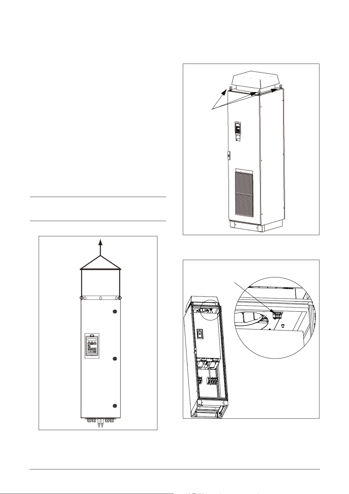
Load: 56 to
74 k g
Lifting eye
Terminals for roof fan
unit supply cables
This chapter describes how to mount the VSD.
Before mounting it is recommended that the installation is planned out first.
• Be sure that the VSD suits the mounting location.
• The mounting site must support the weight of the
VSD.
• Will the VSD continuously withstand vibrations and/
or shocks?
• Consider using a vibration damper.
• Check ambient conditions, ratings, required cooling
air flow, compatibility of the motor, etc.
• Know how the VSD will be lifted and transported.
2.1 Lifting instructions
Note: To prevent personal risks and any damage to the
unit during lifting, it is advised that the lifting methods
described below are used.
Recommended for VSD models -0300 to -1500
Recommended for VSD models -0090 to -0250
Fig. 3 Remove the roof plate.
A
DETAIL A
Fig. 2 Lifting VSD model -0090 to -0250
Fig. 4 Remove roof unit
Mounting 9
Page 13
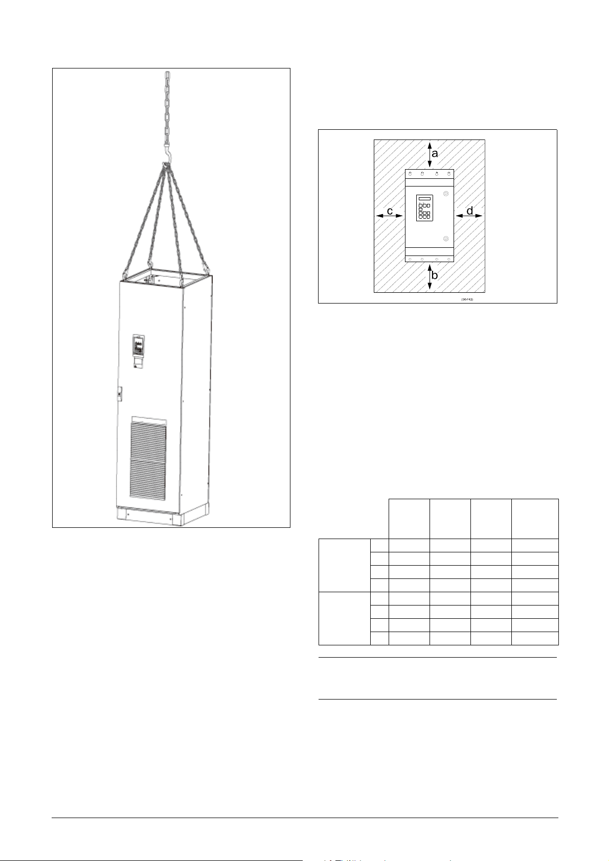
2.2 Stand-alone units
The VSD must be mounted in a vertical position against
a flat surface. Use the template (delivered together with
the VSD) to mark out the position of the fixing holes.
Fig. 6 Variable speed drive mounting models 0003 to 1500
2.2.1 Cooling
Fig. 6 shows the minimum free space required around
the VSD for the models 0003 to 1500 in order to guarantee adequate cooling. Because the fans blow the air
from the bottom to the top it is advisable not to position
an air inlet immediately above an air outlet.
The following minimum separation between two variable speed drives, or a VSD and a non-dissipating wall
must be maintained. Valid if free space on opposite
side.
Fig. 5 Lifting VSD model -0300 to -1500
Table 4 Mounting and cooling
0003-
0018
a 200 200 200 100
F33-F33
(mm)
F33-wall,
wall-one
side
(mm)
NOTE: When a 0300 to 1500 model is placed between
two walls, a minimum distance at each side of 200 mm
must be maintained.
b 200 200 200 0
c0 0 0 0
d0 0 0 0
a 100 100 100 100
b 100 100 100 0
c0 0 0 0
d0 0 0 0
0026-
0046
0090-
0250
0300-
1500
cabinet
10 Mounting
Page 14
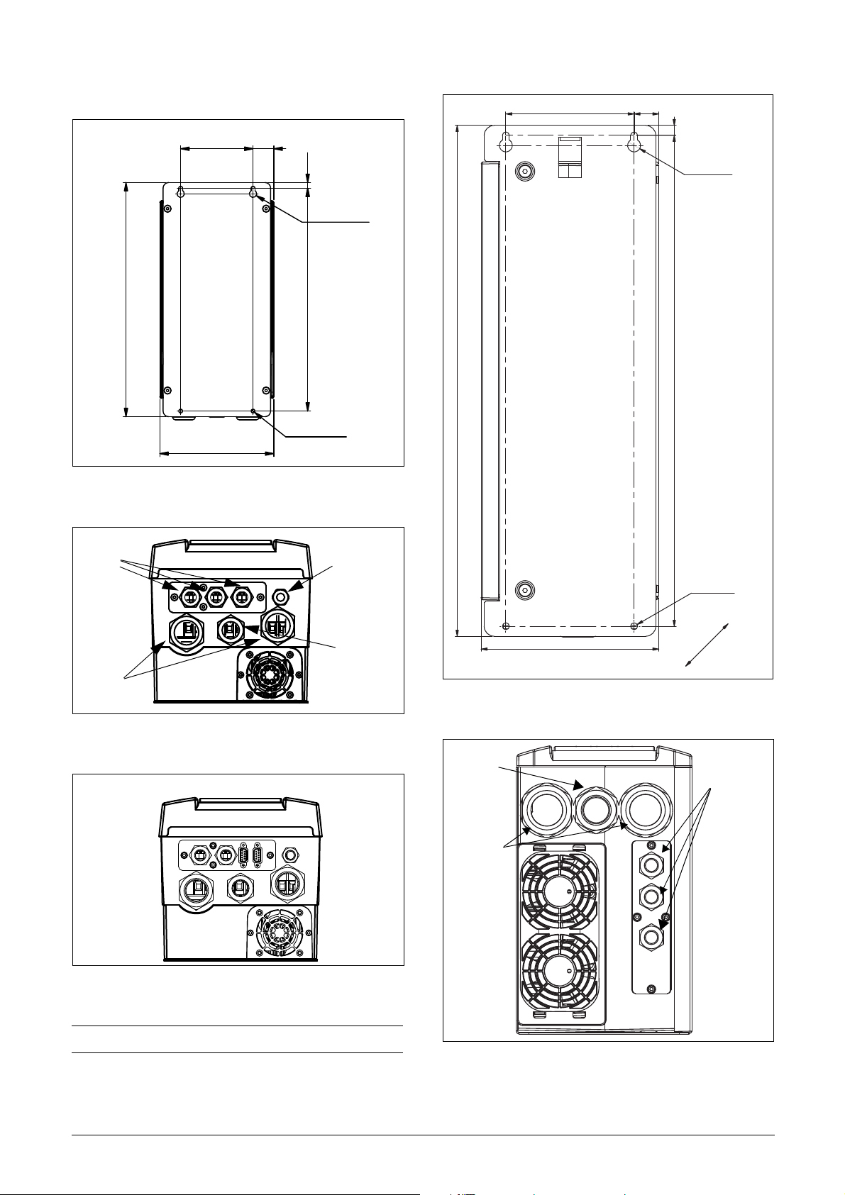
2.2.2 Mounting schemes
Glands
M20
Glands
M32
Gland
M16
Gland
M25
292,1
512
128,5
10492
24,8
178
Ø7 (4x)
Ø13 (2x)
Gland
M25 (0026-0031)
Glands
M20
Glands
M32 (0026-0031)
M32 (0037-0046)
M40 (0037-0046)
128.5 37
10
Ø 13 (2x)
416
396
Ø 7 (4x)
202.6
Fig. 7 JNFX48/52: Model 0003 to 0018 (B)
Fig. 10 JNFX48/52: Model 0026 to 0046 (C)
Fig. 8 JNFX48/52: Model 0003 to 0018 (B)
Fig. 9 JNFX48/52: Model 0003 to 0018 (B), with optional
gland plate
NOTE: Glands for size B and C available as option kit.
Fig. 11 Cable interface for mains, motor and communication,
JNFX48/52: Model 0026 to 0046 (C)
Mounting 11
Page 15

Fig. 12 JNFX40/50: Model 0046 - 0073 (X2)
10570
220
30 160
Ø 13 (2x)
Ø 7 (4x)
590
External
Interface
Glands
M20
Glands
M40
Membrane cable
gland M60
Fig. 14 JNFX48: Model 0090 to 0175 (E) including cable
interface for mains, motor and communication
Fig. 13 Cable interface for mains, motor and communication,
JNFX40/50: Model 0046 - 0073 (X2).
12 Mounting
Page 16

335
344,5
30
922,50
300
22.50
10
925
952,50
150
Ø16(3x)
Ø9(x6)
314
Cable dimensions 27-66 mm
Table 5 Flow rates cooling fans
Frame JNFX Model Flow rate [m3/hour]
J 0860 - 1000
3200
J69 0600 - 0650
K 1200 - 1500
K69 0750 - 1000
4800
NOTE: For the models 0860 to 1500 the mentioned
amount of air flow should be divided equally over the two
cabinets.
2.3.2 Mounting schemes
Fig. 15 JNFX48: Model 0210 to 0250 (F)
JNFX69: Model 0090 to 0175 (F69) including cable
interface for mains, motor and communication
2.3 Cabinet mounting
2.3.1 Cooling
If the variable speed drive is installed in a cabinet, the
rate of airflow supplied by the cooling fans must be taken into consideration.
Table 5 Flow rates cooling fans
Frame JNFX Model Flow rate [m3/hour]
B 0003 - 0018 75
C 0026 – 0031 120
C 0037 - 0046 170
E 0090 - 0175 510
F 0210 - 0250
F69 0090 - 0175
G 0300 - 0375 1020
H 0430 - 0500
H69 0210 - 0375
I 0600 - 0750
I69 0430 - 0500
800
1600
2400
Fig. 16 JNFX48: Model 0300 to 0500 (G and H)
JNFX69: Model 0210 to 0375 (H69)
Mounting 13
Page 17
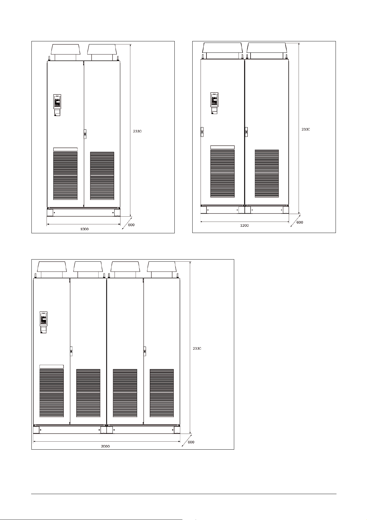
Fig. 17 JNFX48: Model 0600 to 7500 (I)
JNFX69: Model 0430 to 0500 (I69)
Fig. 18 JNFX48: Model 0860 to 1000 (J)
JNFX69: Model 0600 to 0650 (J69)
Fig. 19 JNFX48: Model 1200 to 1500 (K)
JNFX69: Model 0750 to 1000 (K69)
14 Mounting
Page 18
3. Installation
L1
L2
L3
DC-
DC+
R
U
V
W
Screen connection
of motor cables
PE
L
1
L
2
L
3
D
C
-
D
C
+
R
U
V
W
PE
Screen connection
of motor cables
The description of installation in this chapter complies
with the EMC standards and the Machine Directive.
Select cable type and screening according to the EMC
requirements valid for the environment where the VSD
is installed.
3.1 Before installation
Read the following checklist and think through your
application before installation.
• External or internal control.
• Long motor cables (>100m), refer to section Long
motor cables.
• Motors in parallel, refer to menu [213].
•Functions.
• Suitable VSD size in proportion to the motor/application.
• Mount separately supplied option boards according
to the instructions in the appropriate option manual.
If the VSD is temporarily stored before being connected,
please check the technical data for environmental conditions. If the VSD is moved from a cold storage room to
the room where it is to be installed, condensation can
form on it. Allow the VSD to become fully acclimatised
and wait until any visible condensation has evaporated
before connecting the mains voltage.
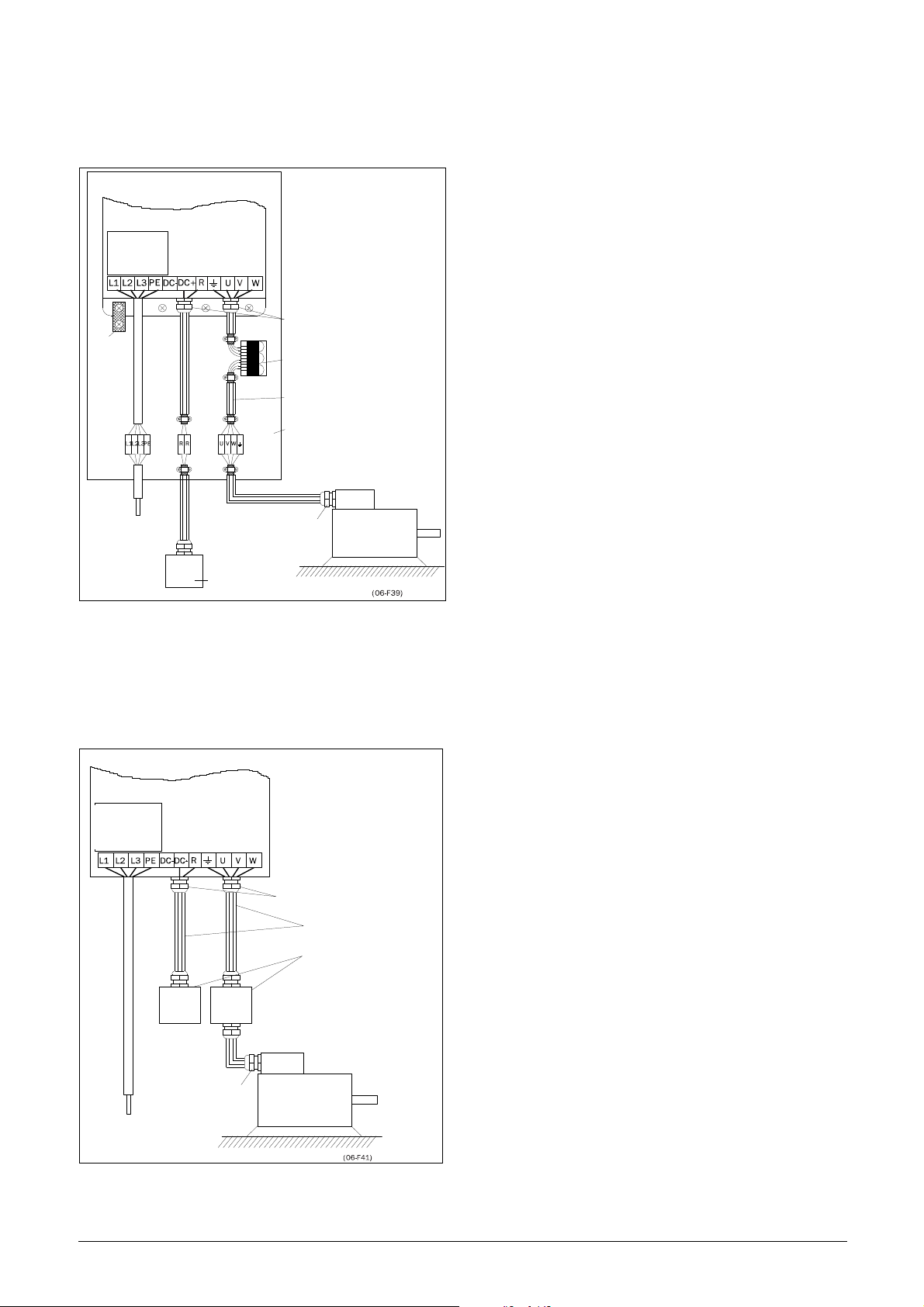
Connect the mains cables according to fig. 20 or 21.
The VSD has as standard a built-in RFI mains filter that
complies with category C3 which suits the Second Environment standard.
Fig. 20 Mains and motor connections, 0003-0018
3.2 Cable connections for
0003 to 0073
3.2.1 Mains cables
Dimension the mains and motor cables according to
local regulations. The cable must be able to carry the
VSD load current.
Recommendations for selecting mains
cables
• To fulfil EMC purposes it is not necessary to use
screened mains cables.
• Use heat-resistant cables, +60°C or higher.
• Dimension the cables and fuses in accordance with
local regulations and the nominal current of the
motor. See table 49, page 165.
• The litz ground connection see fig. 23, is only necessary if the mounting plate is painted. All the variable
speed drives have an unpainted back side and are
therefore suitable for mounting on an unpainted
mounting plate.
Fig. 21 Mains and motor connections, 0026-0046
Table 6 Mains and motor connection
L1,L2,L3
PE
U, V, W
(DC-),DC+,R
Mains supply, 3 -phase
Safety earth (protected earth)
Motor earth
Motor output, 3-phase
Brake resistor, DC-link
connections (optional)
Installation 15
Page 19
NOTE: The Brake and DC-link Terminals are only fitted if
Screen connection
of signal cables
PE
Motor cable
shield connection
the Brake Chopper Option is built-in.
mounting plate.
Connect the motor cables according to U - U, V - V and
W - W, see Fig. 20 and Fig. 21.
WARNING: The Brake Resistor must be
connected between terminals DC+ and R.
WARNING: In order to work safely, the mains
earth must be connected to PE and the
motor earth to .
3.2.2 Motor cables
To comply with the EMC emission standards the variable speed drive is provided with a RFI mains filter. The
motor cables must also be screened and connected on
both sides. In this way a so-called “Faraday cage” is created around the VSD, motor cables and motor. The RFI
currents are now fed back to their source (the IGBTs) so
the system stays within the emission levels.
Recommendations for selecting motor
cables
• Use screened cables according to specification in
table 7. Use symmetrical shielded cable; three
phase conductors and a concentric or otherwise
symmetrically constructed PE conductor, and a
shield.
• When the conductivity of the cable PE conductor is
<50% of the conductivity of the phase conductor, a
separate PE conductor is required.
• Use heat-resistant cables, +60°C or higher.
NOTE: The terminals DC-, DC+ and R are options.
Switches between the motor and the
VSD
If the motor cables are to be interrupted by maintenance switches, output coils, etc., it is necessary that
the screening is continued by using metal housing,
metal mounting plates, etc. as shown in the Fig. 23.
Fig. 24 shows an example when there is no metal
mounting plate used (e.g. if IP54 variable speed drives
are used). It is important to keep the “circuit” closed, by
using metal housing and cable glands.
• Dimension the cables and fuses in accordance with
the nominal output current of the motor. See table
49, page 165.
• Keep the motor cable between VSD and motor as
short as possible.
• The screening must be connected with a large contact surface of preferable 360
° and always at both
ends, to the motor housing and the VSD housing.
When painted mounting plates are used, do not be
afraid to scrape away the paint to obtain as large
contact surface as possible at all mounting points
for items such as saddles and the bare cable
screening. Relying just on the connection made by
the screw thread is not sufficient.
NOTE: It is important that the motor housing has the
same earth potential as the other parts of the machine.
• The litz ground connection, see fig. 24, is only necessary if the mounting plate is painted. All the variable speed drives have an unpainted back side and
are therefore suitable for mounting on an unpainted
Fig. 22 Screen connection of cables.
Pay special attention to the following points:
• If paint must be removed, steps must be taken to
prevent subsequent corrosion. Repaint after making
connections!
• The fastening of the whole variable speed drive
housing must be electrically connected with the
mounting plate over an area which is as large as
possible. For this purpose the removal of paint is
necessary. An alternative method is to connect the
variable speed drive housing to the mounting plate
with as short a length of litz wire as possible.
• Try to avoid interruptions in the screening wherever
possible.
• If the variable speed drive is mounted in a standard
16 Installation
Page 20
cabinet, the internal wiring must comply with the
VSD built into cabinet
VSD
RFI-Filter
(option)
Mains
Metal EMC cable glands
Output coil (option)
Screened cables
Unpainted mounting plate
Metal connector housing
Motor
Metal coupling
nut
Brake resistor
(option)
Mains
(L1,L2,L3,PE)
Litz
Motor
VSD
RFI-Filter
Mains
Metal EMC cable
glands
Screened cables
Metal housing
Brake
resistor
(option)
Output
coils
(option)
Metal connector housing
Motor
Metal cable gland
Mains
EMC standard. Fig. 23 shows an example of a VSD
built into a cabinet.
Fig. 23 Variable speed drive in a cabinet on a mounting plate
Fig. 24 shows an example when there is no metal
mounting plate used (e.g. if IP54 variable speed drives
are used). It is important to keep the “circuit” closed, by
using metal housing and cable glands.
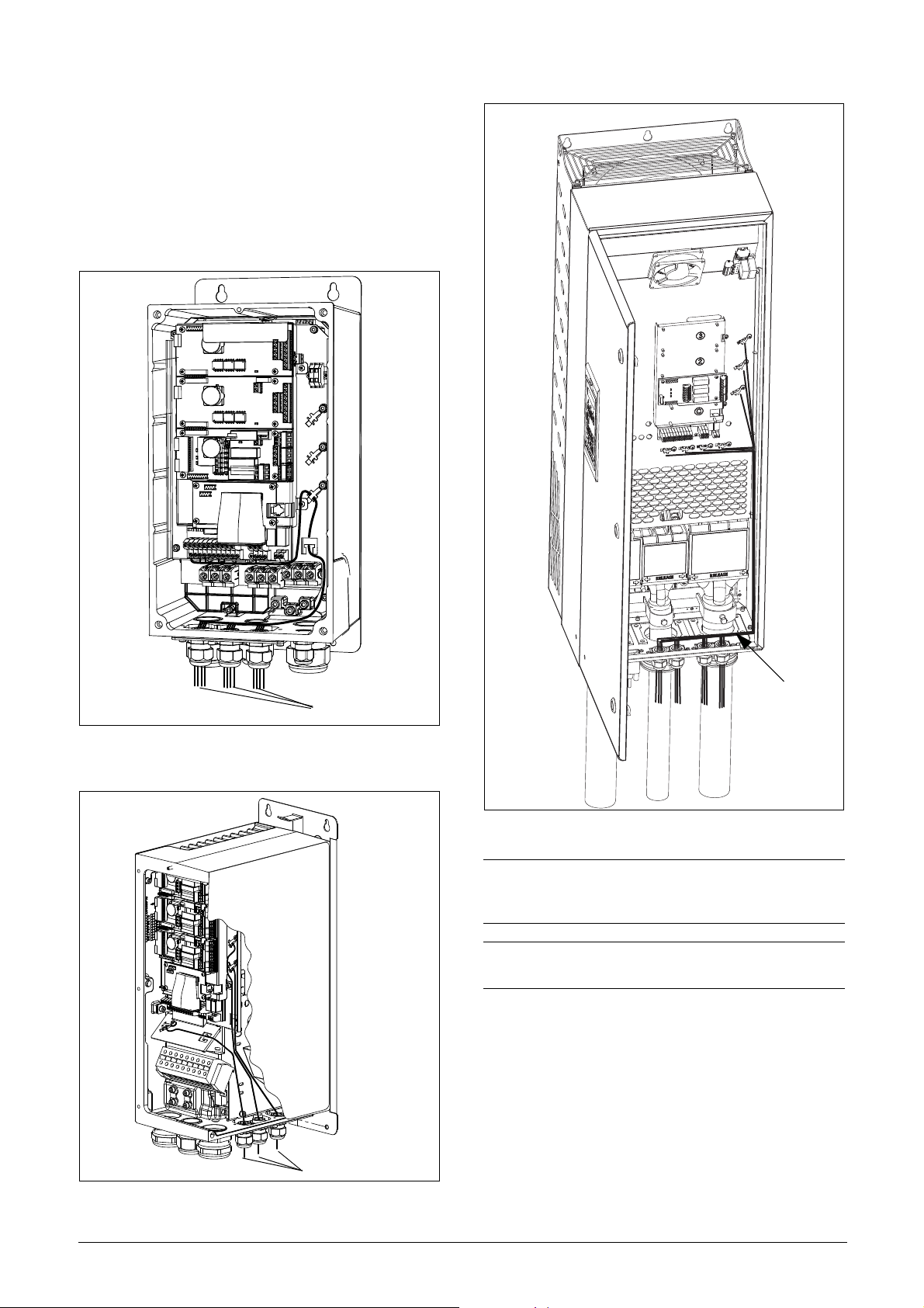
Connect motor cables
1. Remove the cable interface plate from the VSD
housing.
2. Put the cables through the glands.
3. Strip the cable according to Table 8.
4. Connect the stripped cables to the respective motor
terminal.
5. Put the cable interface plate in place and secure
with the fixing screws.
6. Tighten the EMC gland with good electrical contact
to the motor and brake chopper cable screens.
Placing of motor cables
Keep the motor cables as far away from other cables as
possible, especially from control signals. The minimum
distance between motor cables and control cables is
300 mm.
Avoid placing the motor cables in parallel with other
cables.
The power cables should cross other cables at an angle
of 90°.
Long motor cables
If the connection to the motor is longer than 100 m (40
m for models 0003-0018), it is possible that capacitive
current peaks will cause tripping at overcurrent. Using
output coils can prevent this. Contact the supplier for
appropriate coils.
Switching in motor cables
Switching in the motor connections is not advisable. In
the event that it cannot be avoided (e.g. emergency or
maintenance switches) only switch if the current is
zero. If this is not done, the VSD can trip as a result of
current peaks.
Fig. 24 Variable speed drive as stand alone
Installation 17
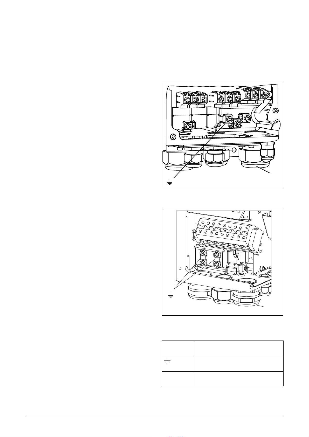
Page 21
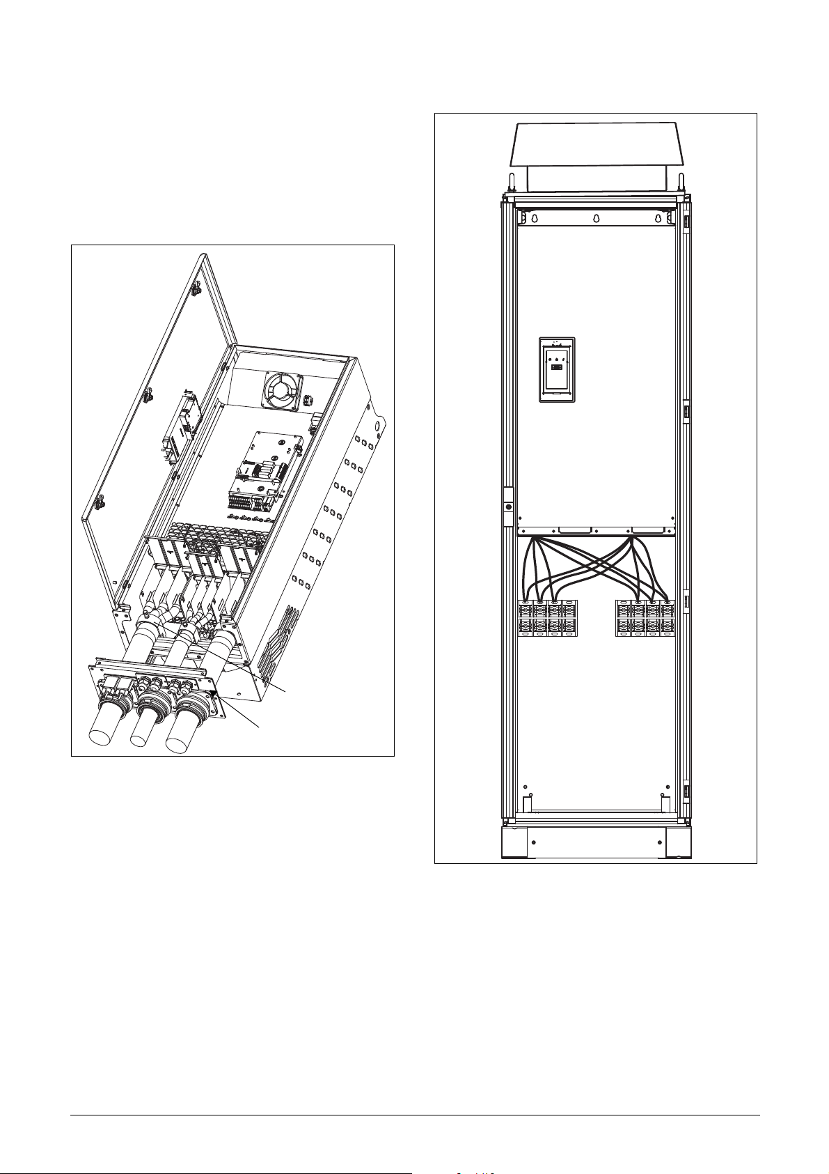
3.3 Connect motor and mains
Cable interface
Clamps for screening
cables for 0090 to 1500
VSD JNFX48-0090 to 0250 and JNFX69-0090
to 0175
To simplify the connection of thick motor and mains
cables to the VSD model JNFX48-0090 to 0250 and
JNFX69-0090 to 0175 the cable interface plate can be
removed.
VSD model 0300 to 1500
Fig. 25 Connecting motor and mains cables
1. Remove the cable interface plate from the VSD
housing.
2. Put the cables through the glands.
3. Strip the cable according to Table 8.
4. Connect the stripped cables to the respective
mains/motor terminal.
5. Fix the clamps on appropriate place and tighten the
cable in the clamp with good electrical contact to
the cable screen.
6. Put the cable interface plate in place and secure
with the fixing screws.
L1 L2 L3 PE PE U V W
Fig. 26 Connecting motor and mains cables
VSD models 0300 to 1500 are supplied with Klockner
Moeller K3x240/4 power clamps.
For all type of wires to be connected the stripping
length should be 32 mm.
18 Installation
Page 22

3.4 Cable specifications
(06-F45-cables only)
MotorMains
Table 7 Cable specifications
Cable Cable specification
Mains
Motor
Control
Power cable suitable for fixed installation for the
voltage used.
Symmetrical three conductor cable with concentric protection (PE) wire or a four conductor cable
with compact low-impedance concentric shield
for the voltage used.
Control cable with low-impedance shield,
screened.
3.5.2 Tightening torque for mains and motor cables
Table 9 Model JNFX48/52 0003 to 0046
Brake chopper Mains/motor
Tightening torque, Nm 1.2-1.4 1.2-1.4
Table 10 Model JNFX40/50 0060 to 0073
All cables 60 A All cables 73 A
Tightening torque, Nm 1.5 3.2
Table 11 Model JNFX48 0090 to 0109
3.5 Stripping lengths
Fig. 27 indicates the recommended stripping lengths
for motor and mains cables.
Table 8 Stripping lengths for mains and motor cables
Mains cable Motor cable
Model
0003-0018 90 10 90 10 20
0026–0046 150 14 150 14 20
0060–0073 130 11 130 11 34
0090-0175 160 16 160 16 41
JNFX480210–0250
JNFX69-00900175
a
(mm)b (mm)a (mm)b (mm)c (mm)
170 24 170 24 46
Brake chopper Mains/motor
Block, mm
Cable diameter, mm
Tightening torque, Nm 14 14
2
2
95 95
16-95 16-95
Table 12 Model JNFX48 0146 to 0175
Brake chopper Mains/motor
Block, mm
Cable diameter, mm
Tightening torque, Nm 14 14 24
2
2
95 150
16-95 35-95 120-150
Table 13 Model JNFX48 0210 to 0250 and JNFX69 0090
to 0175
Brake chopper Mains/motor
Block, mm
Cable diameter, mm
Tightening torque, Nm 14 24 14 24
2
2
150 240
35-95 120-150 35-70 95-240
Fig. 27 Stripping lengths for cables
3.5.1 Dimension of cables and fuses
Please refer to the chapter Technical data, section
14.6, page 160.
Installation 19
Page 23

3.6 Thermal protection on the motor
Standard motors are normally fitted with an internal
fan. The cooling capacity of this built-in fan is dependent on the frequency of the motor. At low frequency, the
cooling capacity will be insufficient for nominal loads.
Please contact the motor supplier for the cooling characteristics of the motor at lower frequency.
WARNING: Depending on the cooling
characteristics of the motor, the application,
the speed and the load, it may be necessary
to use forced cooling on the motor.
Motor thermistors offer better thermal protection for
the motor. Depending on the type of motor thermistor
fitted, the optional PTC input may be used. The motor
thermistor gives a thermal protection independent of
the speed of the motor, thus of the speed of the motor
fan. See the functions, Motor I
2
I
t current [232].
2
t type [231] and Motor
3.7 Motors in parallel
It is possible to have motors in parallel as long as the
total current does not exceed the nominal value of the
VSD. The following has to be taken into account when
setting the motor data:
Menu [221]
Motor Voltage:
Menu [222]
Motor Frequency:
Menu [223]
Motor Power:
Menu [224]
Motor Current:
Menu [225]
Motor Speed:
Menu [227]
Motor Cos PHI:
The motors in parallel must have the
same motor voltage.
The motors in parallel must have the
same motor frequency.
Add the motor power values for the
motors in parallel.
Add the current for the motors in parallel.
Set the average speed for the motors in
parallel.
Set the average Cos PHI value for the
motors in parallel.
20 Installation
Page 24
4. Control Connections
X8
X2
X3
X1
S2S1
S3 S4
X5
X4
X6
X7
U
II
UU
I
I
U
1
12
22
11
41
42 43
31 32
33
51
52
23 4 567 89 10
13 14 15 16 17 18 19 20 21
AO1
AO2
DI4
DI5
DI6 DI7
DO1
DO2
DI8
+24VDI3
DI2
DI1-10V
AI4
AI3AI2
AI1+10V
NC
NC
NO
NO
NO
C
C
C
R01
R02
R03
321
C
Relay outputs
Control
signals
Switches
Option
Control
Panel
Communication
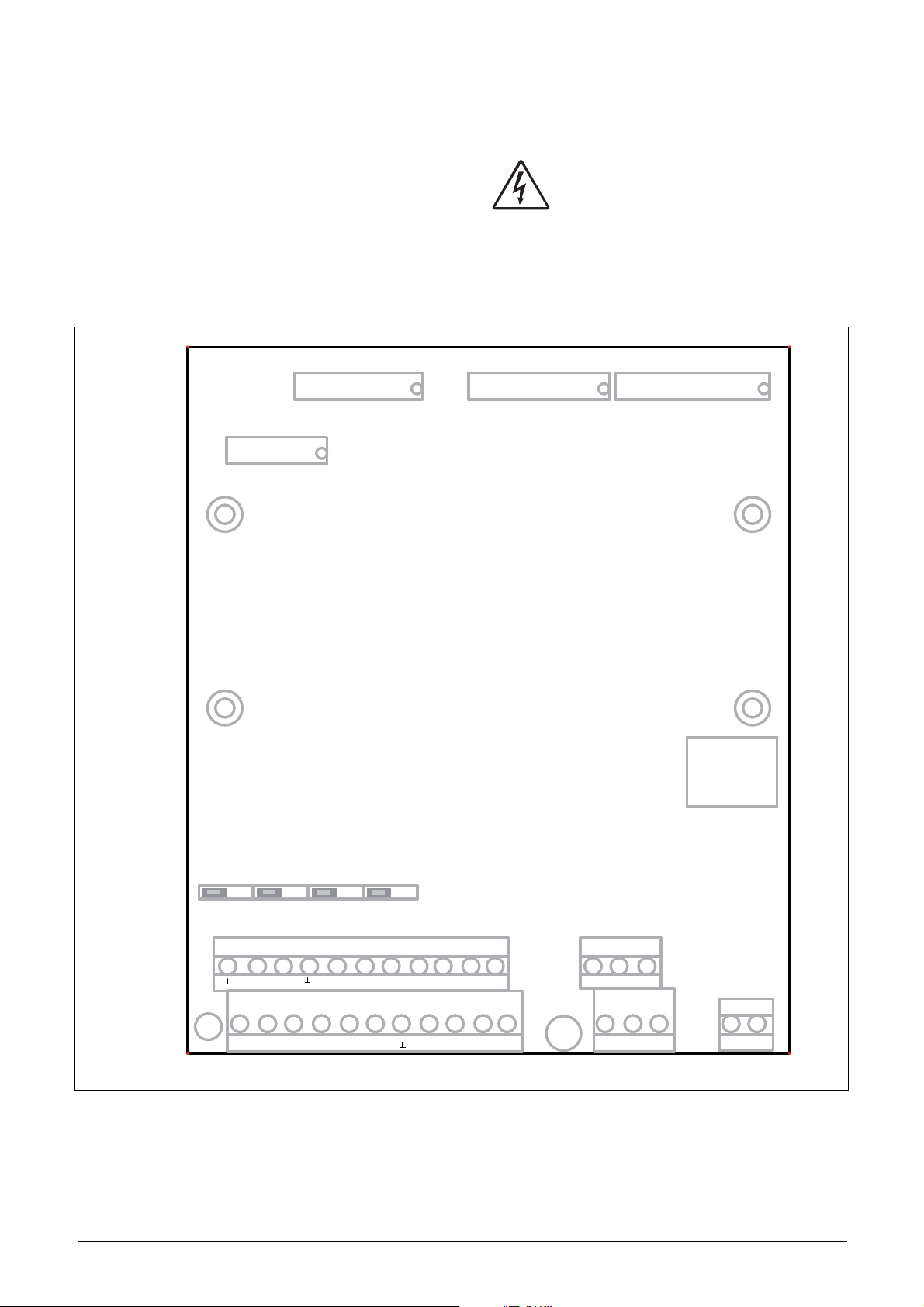
4.1 Control board
Fig. 28 shows the layout of the control board which is
where the parts most important to the user are located.
Although the control board is galvanically isolated from
the mains, for safety reasons do not make changes
while the mains supply is on!
WARNING: Always switch off the mains
voltage and wait at least 5 minutes to allow
the DC capacitors to discharge before
connecting the control signals or changing
position of any switches. If the option External supply is
used, switch of the mains to the option. This is done to
prevent damage on the control board.
Fig. 28 Control board layout
Control Connections 21
Page 25
4.2 Terminal connections
U
I
U
I
U
I
U
I
U
I
U
I
U
I
U
I
The terminal strip for connecting the control signals is
accessible after opening the front panel.
The table describes the default functions for the signals. The inputs and outputs are programmable for
other functions as described in chapter 11. page 53.
For signal specifications refer to chapter 14. page 153.
NOTE: The maximum total combined current for outputs
11, 20 and 21 is 100mA.
Table 14 Control signals
Terminal Name Function (Default)
Outputs
1 +10 V +10 VDC supply voltage
6 -10 V -10 VDC supply voltage
7 Common Signal ground
11 +24 V +24 VDC supply voltage
12 Common Signal ground
15 Common Signal ground
Digital inputs
8DigIn 1RunL (reverse)
9DigIn 2RunR (forward)
10 DigIn 3 Off
16 DigIn 4 Off
17 Di gIn 5 Off
18 DigIn 6 Off
19 DigIn 7 Off
22 DigIn 8 RESET
Digital outputs
20 DigOut 1 Ready
21 DigOut 2 Brake
Analogue inputs
2AnIn 1Process Ref
3AnIn 2Off
4AnIn 3Off
5AnIn 4Off
Analogue outputs
13 Speed Min speed to max speed
14 Torque 0 to max torque
Relay outputs
31 N/C 1
32 COM 1
33 N/O 1
Relay 1 output
Trip, active when the VSD is in a
TRIP condition.
Table 14 Control signals
Terminal Name Function (Default)
41 N/C 2
42 COM 2
43 N/O 2
51 C OM 3
52 N/O 3
NOTE: N/C is opened when the relay is active and N/O is
closed when the relay is active.
Relay 2 output
Run, active when the VSD is
started.
Relay 3 output
Off
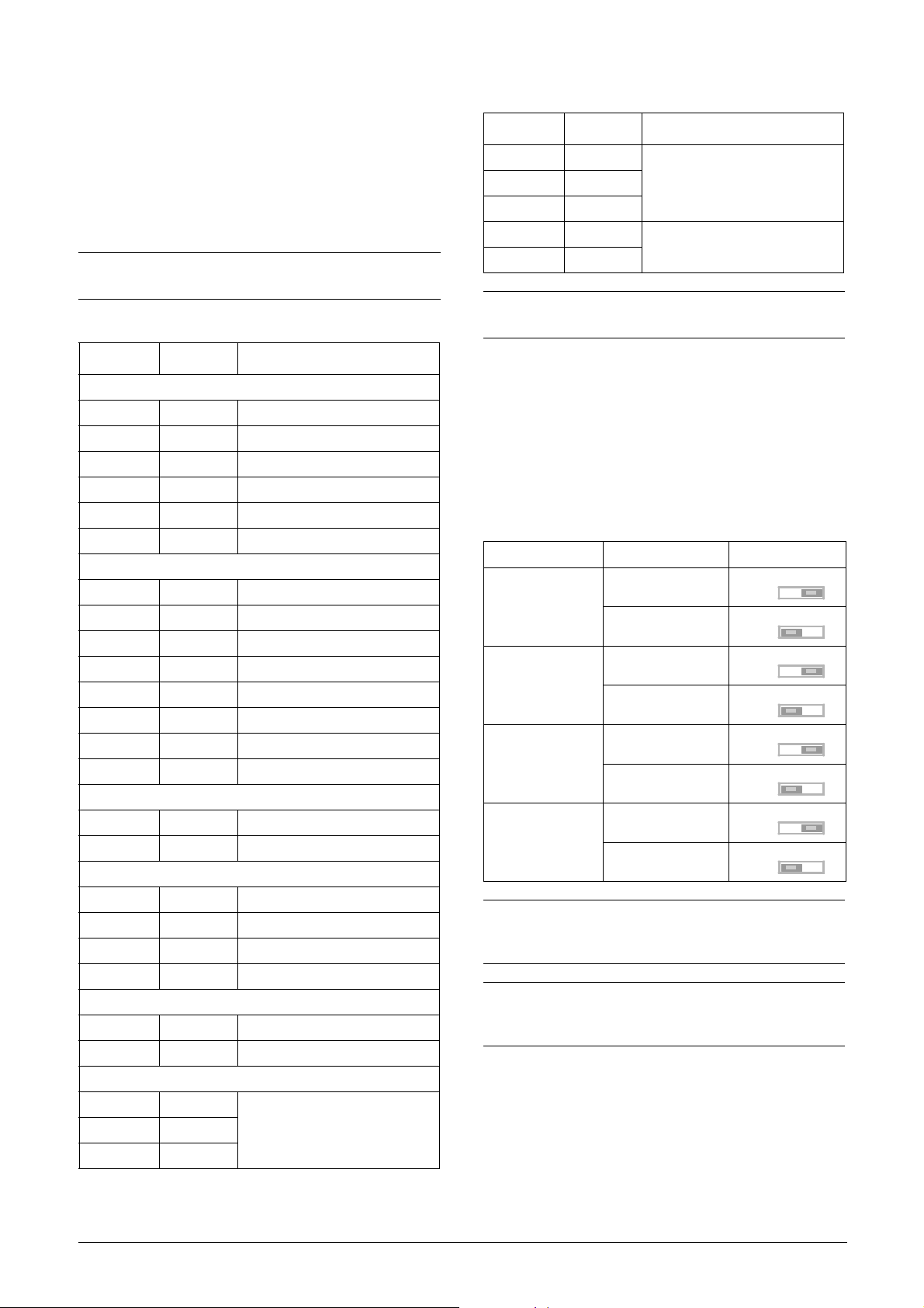
4.3 Inputs configuration
with the switches
The switches S1 to S4 are used to set the input configuration for the 4 analogue inputs AnIn1, AnIn2, AnIn3
and AnIn4 as described in table 15. See Fig. 28 for the
location of the switches.
Table 15 Switch settings
Input Signal type Switch
Voltage
AnIn1
Current (default)
Voltage
AnIn2
Current (default)
Voltage
AnIn3
Current (default)
Voltage
AnIn4
Current (default)
NOTE: Scaling and offset of AnIn1 - AnIn4 can be
configured using the software. See menus [512], [515],
[518] and [51B] in section 11.5, page 106.
NOTE: the 2 analogue outputs AnOut 1 and AnOut 2 can
be configured using the software. See menu [530]
section 11.5.3, page 114
S1
S1
S2
S2
S3
S3
S4
S4
22 Control Connections
Page 26
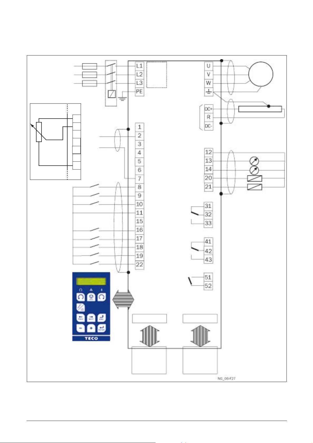
4.4 Connection example
RFIfilter
+10 VDC
AnIn 1: Reference
AnIn 2
AnIn 3
AnIn 4
-10 VDC
Common
DigIn 1:RunL*
DigIn 2:RunR*
DigIn3
+24 VDC
Common
DigIn 4
DigIn 5
DigIn 6
DigIn 7
DigIn 8:Reset*
Common
AnOut 1
AnOut 2
DigOut 1
DigOut 2
Motor
Fieldbus option
or PC
Option board
Other options
0 - 10 V
4 - 20 mA
Alternative for
potentiometer control**
Optional
* Default setting
Relay 1
Relay 2
Relay 3
** The switch S1 is set to U
Fig. 29 gives an overall view of a VSD connection example.
1
2
3
4
5
6
7
Fig. 29 Connection example
Control Connections 23
Page 27
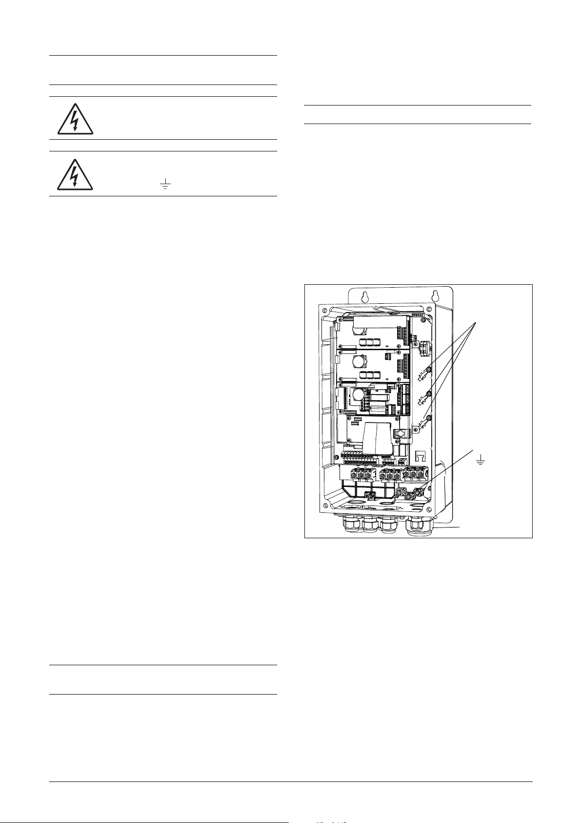
4.5 Connecting the Control
Control signals
Control signals
Control signals
Signals
4.5.1 Cables
The standard control signal connections are suitable for
stranded flexible wire up to 1.5 mm
up to 2.5 mm
2
.
2
and for solid wire
.
Fig. 30 Connecting the control signals 0003 to 0018
Fig. 31 Connecting the control signals 0026 to 0046
Fig. 32 Connecting the control signals 0060 to 0175
NOTE: The screening of control signal cables is
necessary to comply with the immunity levels given in
the EMC Directive (it reduces the noise level).
NOTE: Control cables must be separated from motor and
mains cables.
24 Control Connections
Page 28
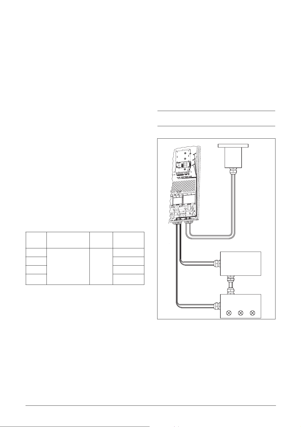
4.5.2 Types of control signals
Control board
Pressure
sensor
(example)
External control
(e.g. in metal housing)
Control consol
Always make a distinction between the different types
of signals. Because the different types of signals can
adversely affect each other, use a separate cable for
each type. This is often more practical because, for
example, the cable from a pressure sensor may be connected directly to the variable speed drive.
We can distinguish between the following types of control signals:
Analogue inputs
Voltage or current signals, (0-10 V, 0/4-20 mA) normally used as control signals for speed, torque and PID
feedback signals.
Analogue outputs
Voltage or current signals, (0-10 V, 0/4-20 mA) which
change slowly or only occasionally in value. In general,
these are control or measurement signals.
Digital
Voltage or current signals (0-10 V, 0-24 V, 0/4-20 mA)
which can have only two values (high or low) and only
occasionally change in value.
angle. Do not let the signal cable go in parallel with the
mains and motor cable.
4.5.4 Single-ended or double-ended connection?
In principle, the same measures applied to motor
cables must be applied to all control signal cables, in
accordance with the EMC-Directives.
For all signal cables as mentioned in section 4.5.2 the
best results are obtained if the screening is connected
to both ends. See Fig. 33.
NOTE: Each installation must be examined carefully
before applying the proper EMC measurements.
Data
Usually voltage signals (0-5 V, 0-10 V) which change
rapidly and at a high frequency, generally data signals
such as RS232, RS485, Profibus, etc.
Relay
Relay contacts (0-250 VAC) can switch highly inductive
loads (auxiliary relay, lamp, valve, brake, etc.).
Signal
type
Analogue Rigid cable:
Digital Screened
Data Screened
Relay Not screened
Maximum wire size
0.14-2.5 mm
Flexible cable:
0.14-1.5 mm
Cable with ferrule:
0.25-1.5 mm
2
2
2
Tightening
torque
0.5 Nm
Cable type
Screened
Example:
The relay output from a variable speed drive which controls an auxiliary relay can, at the moment of switching,
form a source of interference (emission) for a measurement signal from, for example, a pressure sensor.
Therefore it is advised to separate wiring and screening
to reduce disturbances.
Fig. 33 Electro Magnetic (EM) screening of control signal
cables.
4.5.3 Screening
For all signal cables the best results are obtained if the
screening is connected to both ends: the VSD side and
the at the source (e.g. PLC, or computer). See Fig. 33.
It is strongly recommended that the signal cables be
allowed to cross mains and motor cables at a 90°
Control Connections 25
Page 29

4.5.5 Current signals ((0)4-20 mA)
A current signal like (0)4-20 mA is less sensitive to disturbances than a 0-10 V signal, because it is connected
to an input which has a lower impedance (250 Ω) than
a voltage signal (20 kΩ). It is therefore strongly advised
to use current control signals if the cables are longer
than a few metres.
4.5.6 Twisted cables
Analogue and digital signals are less sensitive to interference if the cables carrying them are “twisted”. This is
certainly to be recommended if screening cannot be
used. By twisting the wires the exposed areas are minimised. This means that in the current circuit for any
possible High Frequency (HF) interference fields, no
voltage can be induced. For a PLC it is therefore important that the return wire remains in proximity to the signal wire. It is important that the pair of wires is fully
twisted over 360°.
4.6 Connecting options
The option cards are connected by the optional connectors X4 or X5 on the control board see Fig. 28, page 21
and mounted above the control board. The inputs and
outputs of the option cards are connected in the same
way as other control signals.
26 Control Connections
Page 30

5. Getting Started
VSD
RFI-Filter
Mains
Metal EMC cable
glands
Screened cables
Metal housing
Brake
resistor
(option)
Output
coils
(option)
Metal connector housing
Motor
Metal cable gland
Mains
100
200
300
220
221
210
PREV
ENTERENTER
NEXT
ESCESC
ENTERENTER
ENTERENTER
NEXT
ENTER
ESC
NEXTNEXT
PREVPREV
This chapter is a step by step guide that will show you the
quickest way to get the motor shaft turning. We will show you
two examples, remote control and local control.
We assume that the VSD is mounted on a wall or in a cabinet
as in the chapter 2. page 9.
First there is general information of how to connect mains,
motor and control cables. The next section describes how to
use the function keys on the control panel. The subsequent
examples covering remote control and local control describe
how to program/set the motor data and run the VSD and
motor.
5.1 Connect the mains and motor cables
Dimension the mains and motor cables according to local regulations. The cable must be able to carry the VSD load current.
5.1.1 Mains cables
1. Connect the mains cables as in Fig. 34. The VSD has, as
standard, a built-in RFI mains filter that complies with category C3 which suits the Second Environment standard.
Table 16 Mains and motor connection
L1,L2,L3
PE
U, V, W
Mains supply, 3 -phase
Safety earth
Motor earth
Motor output, 3-phase
WARNING: In order to work safely the mains
earth must be connected to PE and the motor
earth to .
5.2 Using the function keys
5.1.2 Motor cables
2. Connect the motor cables as in Fig. 34. To comply with the
EMC Directive you have to use screened cables and the
motor cable screen has to be connected on both sides: to
the housing of the motor and the housing of the VSD.
Fig. 35 Example of menu navigation when entering motor
voltage
step to lower menu level or confirm changed setting
step to higher menu level or ignore changed setting
step to next menu on the same level
step to previous menu on the same level
increase value or change selection
decrease value or change selection
Fig. 34 Connection of mains and motor cables
Getting Started 27
Page 31

5.3 Remote control
X2
X3
X1
1
12
22
11
41
42
43
31
32
33
51
52
2
3
4
5
6
7
8
9
10
13
14
15
16
17
18
19
20
21
Start
Reference
4-20 mA
+
0V
NEXT
ENTERENTER
NEXT
ENTERENTER
ENTERENTER
ENTERENTER
RESET
In this example external signals are used to control the
VSD/motor.
A standard 4-pole motor for 400 V, an external start
button and a reference value will also be used.
5.3.1 Connect control cables
Here you will make up the minimum wiring for starting.
In this example the motor/VSD will run with right rotation.
To comply with the EMC standard, use screened control
cables with plaited flexible wire up to 1.5 mm
wire up to 2.5 mm
2
.
3. Connect a reference value between terminals 7
(Common) and 2 (AnIn 1) as in Fig. 36.
4. Connect an external start button between terminal
11 (+24 VDC) and 9 (DigIn2, RUNR) as in Fig. 36.
2
or solid
Menu [100], Preferred View is displayed when started.
1. Press to display menu [200], Main Setup.
2. Press and then to display menu [220], Motor
Data.
3. Press to display menu [221] and set motor voltage.
4. Change the value using the and keys. Confirm with .
5. Set motor frequency [222].
6. Set motor power [223].
7. Set motor current [224].
8. Set motor speed [225].
9. Set power factor (cos ϕ) [227].
10.Select supply voltage level used [21B]
11.[229] Motor ID run: Choose Short, confirm with
and give start command .
The VSD will now measure some motor parameters.
The motor makes some beeping sounds but the
shaft does not rotate. When the ID run is finished
after about one minute ("Test Run OK!" is displayed),
press to continue.
Fig. 36 Wiring
5.3.2 Switch on the mains
Close the door to the VSD. Once the mains is switched
on, the internal fan in the VSD will run for 5 seconds.
5.3.3 Set the Motor Data
Enter correct motor data for the connected motor. The
motor data is used in the calculation of complete operational data in the VSD.
Change settings using the keys on the control panel.
For further information about the control panel and
menu structure, see the chapter 9. page 41.
12.Use AnIn1 as input for the reference value. The
default range is 4-20 mA. If you need a 0-10 V reference value, change switch (S1) on control board
and set [512] Anln 1 Set-up to 0-10V.
13.Switch off power supply.
14.Connect digital and analogue inputs/outputs as in
Fig. 36.
15.Ready!
16.Switch on power supply.
5.3.4 Run the VSD
Now the installation is finished, and you can press the
external start button to start the motor.
When the motor is running the main connections are
OK.
28 Getting Started
Page 32

5.4 Local control
NEXT
ENTERENTER
ENTERENTER
NEXT
ENTERENTER
NEXT
ENTERENTER
ESCESC
NEXT
ENTERENTER
ENTERENTER
NEXT
ESCESC
PREV
NEXT
ENTERENTER
Manual control via the control panel can be used to
carry out a test run.
Use a 400 V motor and the control panel.
5.4.1 Switch on the mains
Close the door to the VSD. Once the mains is switched
on, the VSD is started and the internal fan will run for 5
seconds.
5.4.2 Select manual control
Menu [100], Preferred View is displayed when started.
1. Press to display menu [200], Main Setup.
2. Press to display menu [210], Operation.
3. Press to display menu [211], Language.
4. Press to display menu [214], Reference Control.
5. Select Keyboard using the key and press to
confirm.
6. Press to get to menu [215], Run/Stop Control.
7. S e l e ct Keyboard using the key and press to
confirm.
8. Press to get to previous menu level and then
to display menu [220], Motor Data.
5.4.3 Set the Motor Data
Enter correct motor data for the connected motor.
9. Press to display menu [221].
10.Change the value using the and keys. Confirm with .
11.Press to display menu [222].
12.Repeat step 9 and 10 until all motor data is entered.
13.Press twice and then to display menu [100],
Preferred View.
5.4.4 Enter a Reference Value
Enter a reference value.
14.Press until menu [300], Process is displayed.
15.Press to display menu [310], Set/View reference
value.
16.Use the and keys to enter, for example, 300
rpm. We select a low value to check the rotation
direction without damaging the application.
5.4.5 Run the VSD
Press the key on the control panel to run the motor
forward.
If the motor is running the main connections are OK.
Getting Started 29
Page 33

30 Getting Started
Page 34

6. Applications
This chapter contains tables giving an overview of many
different applications/duties in which it is suitable to
use variable speed drives from TECO. Further on you
6.1 Application overview
6.1.1Pumps
Challenge TECO F33 solution Menu
Dry-running, cavitation and overheating damage
the pump and cause downtime.
Sludge sticks to impeller when pump has been running at low speed or been stationary for a while.
Reduces the pump’s efficiency.
Motor runs at same speed despite varying
demands in pressure/flow. Energy is lost and
equipment stressed.
Process inefficiency due to e.g. a blocked pipe, a
valve not fully opened or a worn impeller.
Water hammer damages the pump when stopped.
Mechanical stress on pipes, valves, gaskets, seals.
Pump Curve Protection detects deviation. Sends
warning or activates safety stop.
Automatic pump rinsing function: pump is set to
run at full speed at certain intervals, then return
to normal speed.
PID continuously adapts pressure/flow to the
level required. Sleep function activated when
none is needed.
Pump Curve Protection detects deviation. Warning is sent or safety stop activated.
Smooth linear stops protect the equipment. Eliminates need for costly motorized valves.
will find application examples of the most common
applications and solutions.
411–419, 41C1– 41C9
362–368, 560, 640
320, 380, 342, 354
411–419, 41C1–41C9
331–336
6.1.2 Fans
Challenge TECO F33 solution Menu
Starting a fan rotating in the wrong direction can be
critical, e.g. a tunnel fan in event of a fire.
Draft causes turned off fan to rotate the wrong way.
Starting causes high current peaks and mechanical
stress.
Regulating pressure/flow with dampers causes
high energy consumption and equipment wear.
Motor runs at same speed despite varying
demands in pressure/flow. Energy is lost and
equipment stressed.
Process inefficiency due to e.g. a blocked filter, a
damper not fully opened or a worn belt.
Fan is started at low speed to ensure correct
direction and proper function.
Motor is gradually slowed to complete stop before
starting. Avoids blown fuses and breakdown.
Automatic regulation of pressure/flow with motor
speed gives more exact control.
PID continuously adapts to the level required.
Sleep function is activated when none is needed.
Load Curve Protection detects deviation. Warning
is sent or safety stop activated.
219, 341
219, 33A, 335
321, 354
320, 380, 342, 354
411–419, 41C1–41C9
Applications 31
Page 35

6.1.3 Compressors
Challenge TECO F33 solution Menu
Compressor is damaged when cooling media
enters the compressor screw.
Pressure is higher than needed, causing leaks,
stress on the equipment and excessive air use.
Motor runs at same speed when no air is compressed. Energy is lost and equipment stressed.
Process inefficiency and energy wasted due to e.g.
the compressor idling.
6.1.4 Blowers
Challenge TECO F33 solution Menu
Difficult to compensate for pressure fluctuations.
Wasted energy and risk of production stop.
Motor runs at same speed despite varying
demands. Energy is lost and equipment stressed.
Process inefficiency due to e.g. a broken damper, a
valve not fully opened or a worn belt.
Overload situation is quickly detected and safety
stop can be activated to avoid breakdown.
Load Curve Protection function detects deviation.
Warning is sent or safety stop activated.
PID continuously adapts to the level required.
Sleep function activated when none is needed.
Load Curve Protection quickly detects deviation.
Warning is sent or safety stop activated.
PID function continuously adapts pressure to the
level required.
PID continuously adapts air flow to level required.
Sleep function activated when none is needed.
Load Curve Protection quickly detects deviation.
Warning is sent or safety stop activated.
411–41A
411–419, 41C1–41C9
320, 380, 342, 354
411–419, 41C1–41C9
320, 380
320, 380, 342, 354
411–419, 41C1–41C9
32 Applications
Page 36

7. Main Features
{
(NG06-F03_1)
Run/Stop
-
Torques
-
Controllers
-
Limits/Prot.
-
-Max Alarm
Parameter Set A
Set B
Set C
Set D
11
10
16
Set Ctrl1
Set Ctrl2
+24 V
This chapter contains descriptions of the main features
of the VSD.
7.1 Parameter sets
Parameter sets are used if an application requires different settings for different modes. For example, a
machine can be used for producing different products
and thus requires two or more maximum speeds and
acceleration/deceleration times. With the four parameter sets different control options can be configured with
respect to quickly changing the behaviour of the VSD. It
is possible to adapt the VSD online to altered machine
behaviour. This is based on the fact that at any desired
moment any one of the four parameter sets can be activated during Run or Stop, via the digital inputs or the
control panel and menu [241].
Each parameter set can be selected externally via a digital input. Parameter sets can be changed during operation and stored in the control panel.
NOTE: The only data not included in the parameter set is
Motor data 1-4, (entered separately), language,
communication settings, selected set, local remote, and
keyboard locked.
Define parameter sets
When using parameter sets you first decide how to
select different parameter sets. The parameter sets
can be selected via the control panel, via digital inputs
or via serial communication. All digital inputs and virtual inputs can be configured to select parameter set.
The function of the digital inputs is defined in the menu
[520].
Fig. 37 shows the way the parameter sets are activated
via any digital input configured to Set Ctrl 1 or Set Ctrl
2.
Fig. 37 Selecting the parameter sets
Select and copy parameter set
The parameter set selection is done in menu [241],
Select Set. First select the main set in menu [241], normally A. Adjust all settings for the application. Usually
most parameters are common and therefore it saves a
lot of work by copying set A>B in menu [242]. When
parameter set A is copied to set B you only change the
parameters in the set that need to be changed. Repeat
for C and D if used.
With menu [242], Copy Set, it is easy to copy the complete contents of a single parameter set to another
parameter set. If, for example, the parameter sets are
selected via digital inputs, DigIn 3 is set to Set Ctrl 1 in
menu [523] and DigIn 4 is set to Set Ctrl 2 in menu
[524], they are activated as in Table 17.
Activate the parameter changes via digital input by setting menu [241], Select Set to DigIn.
Table 17 Parameter set
Parameter set Set Ctrl 1 Set Ctrl 2
A00
B10
C01
D11
NOTE: The selection via the digital inputs is immediately
activated. The new parameter settings will be activated
on-line, also during Run.
NOTE: The default parameter set is parameter set A.
Examples
Different parameter sets can be used to easily change
the setup of a VSD to adapt quickly to different application requirements. For example when
• a process needs optimized settings in different
stages of the process, to
- increase the process quality
- increase control accuracy
- lower maintenance costs
- increase operator safety
With these settings a large number of options are available. Some ideas are given here:
Multi frequency selection
Within a single parameter set the 7 preset references
can be selected via the digital inputs. In combination
with the parameter sets, 28 preset references can be
selected using all 4 digital inputs: DigIn1, 2 and 3 for
selecting preset reference within one parameter set
Main Features 33
Page 37

and DigIn 4 and DigIn 5 for selecting the parameter
sets.
Bottling machine with 3 different products
Use 3 parameter sets for 3 different Jog reference
speeds when the machine needs to be set up. The 4th
parameter set can be used for “normal” remote control
when the machine is running at full production.
Manual - automatic control
If in an application something is filled up manually and
then the level is automatically controlled using PID regulation, this is solved using one parameter set for the
manual control and one for the automatic control.
7.1.1 One motor and one parameter
set
This is the most common application for pumps and
fans.
Once default motor M1 and parameter set A have been
selected:
1. Enter the settings for motor data.
One motor must stop before changing to an other
motor.
1. Select parameter set A in menu [241].
2. Select motor M1 in menu [212].
3. Enter motor data and settings for other parameters
e.g. inputs and outputs.
4. Select parameter set B in menu [241].
5. Select M2 in menu [212].
6. Enter motor data and settings for other parameters
e.g. inputs and outputs.
7.1 .4 Autor eset at t rip
For several non-critical application-related failure conditions, it is possible to automatically generate a reset
command to overcome the fault condition. The selection can be made in menu [250]. In this menu the maximum number of automatically generated restarts
allowed can be set, see menu [251], after this the VSD
will stay in fault condition because external assistance
is required.
2. Enter the settings for other parameters e.g. inputs
and outputs
7.1.2 One motor and two parameter
sets
This application is useful if you for example have a
machine running at two different speeds for different
products.
Once default motor M1 is selected:
1. Select parameter set A in menu [241].
2. Enter motor data in menu [220].
3. Enter the settings for other parameters e.g. inputs
and outputs.
4. If there are only minor differences between the settings in the parameter sets, you can copy parameter
set A to parameter set B, menu [242].
5. Enter the settings for parameters e.g. inputs and
outputs.
Note: Do not change motor data in parameter set B.
Example
The motor is protected by an internal protection for thermal overload. When this protection is activated, the
VSD should wait until the motor is cooled down enough
before resuming normal operation. When this problem
occurs three times in a short period of time, external
assistance is required.
The following settings should be applied:
• Insert maximum number of restarts; set menu [251]
to 3.
•Activate Motor I
menu [25A] to 300 s.
• Set relay 1, menu [551] to AutoRst Trip; a signal will
be available when the maximum number of restarts
is reached and the VSD stays in fault condition.
• The reset input must be constantly activated.
2
t to be automatically reset; set
7.1.5 Reference priority
The active speed reference signal can be programmed
from several sources and functions. The table below
shows the priority of the different functions with
regards to the speed reference.
7.1.3 Two motors and two parameter
sets
This is useful if you have a machine with two motors
that can not run at the same time, such as a cable
winding machine that lifts up the reel with one motor
and then turns the wheel with the other motor.
34 Main Features
Table 18 Reference priority
Jog
Mode
On/Off On/Off On/Off Option cards
On On/Off On/Off Jog Ref
Off On On/Off Preset Ref
Off Off On Motor pot commands
Preset
Reference
Motor Pot Ref. Signal
Page 38

7.1.6 Preset references
X
X1
1
12
22
11
2
3
4
5
6
7
8
9
10
13
14
15
16
17
18
19
20
21
RunR
Reset
+24 V
!
The VSD is able to select fixed speeds via the control of
digital inputs. This can be used for situations where the
required motor speed needs to be adapted to fixed values, according to certain process conditions. Up to 7
preset references can be set for each parameter set,
which can be selected via all digital inputs that are set
to Preset Ctrl1, Preset Ctrl2 or Preset Ctrl3. The amount
digital inputs used that are set to Preset Ctrl determines the number of Preset References available;
using 1 input gives 2 speeds, using 2 inputs gives 4
speeds and using 3 inputs gives 8 speeds.
Example
The use of four fixed speeds, at 50 / 100 / 300 / 800
rpm, requires the following settings:
• Set DigIn 5 as first selection input; set [525] to Pre-
set Ctrl1.
• Set DigIn 6 as second selection input; set [526] to
Preset Ctrl2.
• Set menu [341], Min Speed to 50 rpm.
• Set menu [362], Preset Ref 1 to 100 rpm.
• Set menu [363], Preset Ref 2 to 300 rpm.
• Set menu [364], Preset Ref 3 to 800 rpm.
With these settings, the VSD switched on and a RUN
command given, the speed will be:
• 50 rpm, when both DigIn 5 and DigIn 6 are low.
• 100 rpm, when DigIn 5 is high and DigIn 6 is low.
• 300 rpm, when DigIn 5 is low and DigIn 6 is high.
• 800 rpm, when both DigIn 5 and DigIn 6 are high.
Fig. 38 Default setting Run/Reset commands
The inputs are default set for level-control. The rotation
is determined by the setting of the digital inputs.
Enable and Stop functions
Both functions can be used separately or simultaneously. The choice of which function is to be used
depends on the application and the control mode of the
inputs (Level/Edge [21A]).
NOTE: In Edge mode, at least one digital input must be
programmed to “stop”, because the Run commands are
otherwise only able to start the VSD.
Enable
Input must be active (HI) to allow any Run signal. If the
input is made LOW, the output of the VSD is immediately disabled and the motor will coast.
7.2 Remote control functions
Operation of the Run/Stop/Enable/Reset functions
CAUTION: If the Enable function is not
programmed to a digital input, it is considered
to be active internally.
As default, all the run/stop/reset related commands
are programmed for remote operation via the inputs on
the terminal strip (terminals 1-22) on the control board.
With the function Run/Stp Ctrl [215] and Reset Control
[216], this can be selected for keyboard or serial communication control.
Stop
If the input is low then the VSD will stop according to
the selected stop mode set in menu [33B] Stop Mode.
Fig. 39 shows the function of the Enable and the Stop
input and the Stop Mode=Decel [33B].
NOTE: The examples in this paragraph do not cover all
possibilities. Only the most relevant combinations are
given. The starting point is always the default setting
(factory) of the VSD.
Default settings of the Run/Stop/
Enable/Reset functions
The default settings are shown in Fig. 38. In this example the VSD is started and stopped with DigIn 2 and a
reset after trip can be given with DigIn 8.
To run the input must be high.
NOTE: Stop Mode=Coast [33B] will give the same
behaviour as the Enable input.
Main Features 35
Page 39

(06-F104_NG)
STOP
(STOP=DECEL)
OUTPUT
SPEED
ENABLE
OUTPUT
SPEED
(or if Spinstart is selected)
!
X1
1
12
22
11
2
3
4
5
6
7
8
9
10
13
14
15
16
17
18
19
20
21
Stop
Reset
+24 V
RunL
RunR
Enable
(06-F103new_1)
INPUTS
OUTPUT
STATUS
ENABLE
STOP
RUN R
RUN L
Right rotation
Left rotation
Standstill
Fig. 39 Functionality of the Stop and Enable input
Reset and Autoreset operation
If the VSD is in Stop Mode due to a trip condition, the
VSD can be remotely reset by a pulse (“low” to “high”
transition) on the Reset input, default on DigIn 8.
Depending on the selected control method, a restart
takes place as follows:
Level-control
If the Run inputs remain in their position the VSD will
start immediately after the Reset command is given.
t
Fig. 40 Example of wiring for Run/Stop/Enable/Reset inputs
The Enable input must be continuously active in order
t
to accept any run-right or run-left command. If both
RunR and RunL inputs are active, then the VSD stops
according to the selected Stop Mode. Fig. 41 gives an
example of a possible sequence.
Edge-control
After the Reset command is given a new Run command
must be applied to start the VSD again.
Autoreset is enabled if the Reset input is continuously
active. The Autoreset functions are programmed in
menu Autoreset [250].
Run Inputs Level-controlled.
The inputs are set as default for level-control. This
means that an input is activated by making the input
continuously “High”. This method is commonly used if,
for example, PLCs are used to operate the VSD.
The examples given in this and the following paragraphs follow the input selection shown in Fig. 40.
36 Main Features
NOTE: If the control commands are programmed for
Keyboard control or Com, Autoreset is not possible.
CAUTION: Level-controlled inputs DO NOT
comply with the Machine Directive, if the inputs
are directly used to start and stop the machine.
Fig. 41 Input and output status for level-control
Run Inputs Edge-controlled
Menu [21A] Start signal Level/Edge must be set to
Edge to activate edge control. This means that an input
is activated by a “low” to “high” transition or vice versa.
NOTE: Edge-controlled inputs comply with the Machine
Directive (see chapter EMC and Machine Directive), if
the inputs are directly used for starting and stopping the
machine.
Page 40

See Fig. 40. The Enable and Stop input must be active
(06-F94new_1)
INPUTS
ENABLE
STOP
RUN R
RUN L
OUTPUT
STATUS
Right rotation
Left rotation
Standstill
VSD
continuously in order to accept any run-right or run-left
command. The last edge (RunR or RunL) is valid. Fig.
42 gives an example of a possible sequence.
7.4 Using the Control Panel
Memory
Data can be copied from the VSD to the memory in the
control panel and vice versa. To copy all data (including
parameter set A-D and motor data) from the VSD to the
control panel, select Copy to CP[244], Copy to CP.
To copy data from the control panel to the VSD, enter
the menu [245], Load from CP and select what you
want to copy.
The memory in the control panel is useful in applications with VSDs without a control panel and in applications where several variable speed drives have the
same setup. It can also be used for temporary storage
of settings. Use a control panel to upload the settings
from one VSD and then move the control panel to
another VSD and download the settings.
NOTE: Load from and copy to the VSD is only possible
when the VSD is in stop mode.
Fig. 42 Input and output status for edge-control
7.3 Performing an
Identification Run
To get the optimum performance out of your VSD/
motor combination, the VSD must measure the electrical parameters (resistance of stator winding, etc.) of
the connected motor. See menu [229], Motor ID-Run.
Fig. 43 Copy and load parameters between VSD and control
panel
Main Features 37
Page 41

7.5 Load Monitor and Process
Protection [400]
7.5.1 Load Monitor [410]
The monitor functions enable the VSD to be used as a
load monitor. Load monitors are used to protect
machines and processes against mechanical overload
and underload, such as a conveyer belt or screw conveyer jamming, belt failure on a fan or a pump dry running. The load is measured in the VSD by the calculated
motor shaft torque. There is an overload alarm (Max
Alarm and Max Pre-Alarm) and an underload alarm
(Min Alarm and Min Pre-Alarm).
The Basic Monitor type uses fixed levels for overload
and underload (pre-)alarms over the whole speed
range. This function can be used in constant load applications where the torque is not dependent on the
speed, e.g. conveyor belt, displacement pump, screw
pump, etc.
For applications with a torque that is dependent on the
speed, the Load Curve monitor type is preferred. By
measuring the actual load curve of the process, characteristically over the range of minimum speed to maximum speed, an accurate protection at any speed can
be established.
The max and min alarm can be set for a trip condition.
The pre-alarms act as a warning condition. All the
alarms can be monitored on the digital or relay outputs.
The autoset function automatically sets the 4 alarm levels whilst running: maximum alarm, maximum prealarm, minimum alarm and minimum pre-alarm.
Fig. 44 gives an example of the monitor functions for
constant torque applications
38 Main Features
Page 42

.
Ramp-down phase
Stationary phase
Stationary phaseRamp-up phase
[413] Ramp Alarm=On
[411] Alarm Select=Max or Max0Min
[413] Ramp Alarm=On or Off
[411] Alarm Select=Max or Max0Min
[411] Alarm Select=Max or Max0Min
[411] Alarm Select=Max or Max0Min
[413] Ramp Alarm=On or Off
[413] Ramp Alarm=On
Must be <t (or t´) otherwise no (pre)alarm
[4192] MinAlarmDel (0.1s)
[4172] MaxPreAlDel (0.1s)
[414] Start Delay (0.2s)
Must be <t (or t´) otherwise no (pre)alarm
[4161] MaxAlarmMar (15%)
[4171] MaxPreAlMar (10%)
100%
Default: T
NOM
or
Autoset: T
MOMENTARY
[4191] MinAlarmMar (15%)
[4181] MinPreAlMar (10%)
Must be elapsed before first (pre)alarm
Max Alarm
Max PreAlarm
Min Alarm
Min PreAlarm
[4162] MaxAlarmDel (0.1s)
[4172] MaxPreAlDel (0.1s)
[4162] MaxAlarmDel (0.1s)
[4182] MinPreAlDel (0.1s)
[4192] MinAlarmDel (0.1s)
[4182] MinPreAlDel (0.1s)
Tor que [ %]
t [s]
[41B]
Fig. 44
Main Features 39
Page 43

7.6 Pump function
Δ
FLOW /
PRESSURE
Add pump
FREQUENCY (master pump P)
Stop pump
P1=on P2=on P3=on P4=on P5=on P6=on
P=on
TIM E
FLOW /
PRESSURE
(50-PC-3_1)
7.6.1 Introduction
A maximun of 4 pumps can be controlled with the
standard F33 variable speed drive.
If I/O Board options are installed, a maximum of 7
pumps can be controlled. The I/O Board can also be
used as a general extended I/O.
The Pump Control function is used to control a number
of drives (pumps, fans, etc., with a maximum of 3 additional drives per I/O-board connected) of which one is
always driven by the F33. Other names for this kind of
controllers are ‘Cascade controller’ or ‘Hydrophore controller’.
Depending on the flow, pressure or temperature, additional pumps can be activated via the appropriate signals by the output relays of the F33 and/or the I/O
Board. The system is developed in such a way that one
F33 will be the master of the system.
Select relay on the control board or on an option board.
The relays are set to functions for controlling pumps. In
the pictures in this section, the relays are named
R:Function, e.g. R:SlavePump1, which means a relay on
the control board or on a option board set to function
SlavePump1.
All additional pumps can be activated via an VSD, soft
starter, Y/
or D.O.L. switches.
Fig. 46 Pressure control with pump control option
Pumps in parallel will operate as a flow controller, See
Fig. 40.
Fig. 45 Flow control with pump control option
Pumps in series will operate as a pressure controller
see Fig. 41. The basic control principle is shown in Fig.
42.
NOTE: Read this instruction manual carefully before
commencing installation, connecting or working with
the variable speed drive with Pump Control option.
40 Main Features
Fig. 47 Basic Control Principle
Page 44

7.6.2 Fixed MASTER
See menu:
[393] Select Drive
[39H] to [39N] Run Time 1 - 6, Pump
[554] to [55C] Relays
See menu:
[393] to [396]
[553] to [55C]
This is the default setting of the Pump Control. The F33
controls the Master pump which is always running. The
relay outputs start and stop the other pumps P1 to P6,
depending on flow/pressure. In this configuration a
maximum of 7 pumps can be controlled, see Fig. 43. To
equalize the lifetime of the additional pumps it is possible to select the pumps depending on the run time history of each pump.
Fig. 49 Alternating MASTER Control
NOTE: The pumps MUST have all the same power.
Fig. 48 Fixed MASTER control
NOTE: The pumps MAY have different powers, however
the MASTER pump MUST always be the largest.
7.6.3 Alternating MASTER
With this function the Master pump is not fixed to the
F33 all the time. After the VSD is powered up or started
again after a stop or sleep mode the Master pump is
selected via the relay set to function Master Pump. section 7.6.7 on page 44 shows a detailed wiring diagram
with 3 pumps. The purpose of this function is that all
pumps are used equally, so the lifetime of all pumps,
including the Master pump, will be equalized. Maximum
6 pumps can be controlled with this function.
7.6.4 Feedback ‘Status’ input
In this example the additional pumps are controlled by
an other kind of drive (e.g. soft starter, frequency
inverter, etc.). The digital inputs on the I/O Board can
be programmed as a “Error” input for each pump. If a
drive fails the digital input will monitor this and the
PUMP CONTROL option will not use that particular drive
anymore and automatically switch to another drive.
This means that the control continues without using
this (faulty) drive. This function can also be used to
manually stop a particular pump for maintenance purposes, without shutting down the whole pump system.
Of course the maximum flow/pressure is then limited to
the maximum pump power of the remaining pumps.
Main Features 41
Page 45

Fig. 50 Feedback “Status” input
See menu:
[529] to [52H] Digital Input
[554] to [55C] Relay
See menu:
[554] to [55C] Relays
[55D4] to [55DC] Mode
7.6.5 Fail safe operation
Some pump systems must always have a minimum flow
or pressure level, even if the frequency inverter is
tripped or damaged. So at least 1 or 2 (or maybe all)
additional pumps must keep running after the inverter
is powered down or tripped. This kind of “safe” pump
operation can be obtained by using the NC contacts of
the pump control relays. These can be programmed for
each individual additional pump. In this example
pumps P5 and P6 will run at maximum power if the
inverter fails or is powered down.
Fig. 51 Example of “fail safe” operation
42 Main Features
Page 46

7.6.6 PID control
See menu:
[381] to [385]
[553] to [55C]
[411] to [41C]
Set
Value
Feedback
Value
Flow/Pressure
measurement
When using the Pump Control option it is mandatory to
activate the PID controller function. Analogue inputs
AnIn1 to AnIn4 can be set as functions for PID set values and/or feedback values.
Fig. 52 PID control
Main Features 43
Page 47

7.6.7 Wiring Alternating Master
!
K1S
B2:R1
Slave
Pump1
K1M
B1:R1
Master
Pump1
~
N
(NG_50-PC-11_3)
K2M
B1:R2
Master
Pump2
K2S
B2:R2
Slave
Pump2
K3M
B1:R3
Master
Pump3
K3S
B2:R3
Slave
Pump3
K1S
K1M
K2M
K2S
K3MK3S
Fig. 48 and Fig. 49 show the relay functions
MasterPump1- 6 and SlavePump1-6. The Master and
Additional contactors also interlock with each other to
prevent dual powering of the pump and damage to the
inverter. (K1M/K1S, K2M/ K2S, K3M/K3S). Before
running, the F33 will select a pump to be Master,
depending on the pump run times.
CAUTION: The wiring for the Alternating
Master control needs special attention and
should be wired exactly as described here,
to avoid destructive short circuit at the output of the
inverter.
Fig. 53 Power connections for Alternating MASTER circuit
with 3 pumps
Fig. 54 Control connections for Alternating MASTER circuit
with 3 pumps
44 Main Features
Page 48

7.6.8 Checklist And Tips
1. Main Functions
Start by choosing which of the two main functions to use:
- "Alternating MASTER" function
In this case the “Master” pump can be alternated, although this function needs slightly more complicated wiring than the
“Fixed MASTER” function described below. The I/O Board option is necessary.
- "Fixed MASTER" function:
One pump is always the master, only the additional pumps alternate.
Notice that there is a big difference in the wiring of the system between these main functions, so it not possible to switch
between these 2 functions later on. For further information see section 7.6.2, page 41.
2. Number of pumps/drives
If the system consists of 2 or 3 pumps the I/O Board option is not needed. However, this does mean that the following
functions are not then possible:
- "Alternating MASTER" function
- With isolated inputs
With the I/O Board option installed, the maximum number of pumps is:
- 6 pumps if "Alternating MASTER" function is selected. (see section 7.6.3 on page 41)
- 7 pumps if "Fixed MASTER" function is selected. (see section 7.6.2, page 41)
3. Pump size
- "Alternating MASTER" function:
The sizes of the pumps must be equal.
- "Fixed MASTER" function:
The pumps may have different power sizes, but the master pump (F33) must always have the greatest power.
4. Programming the Digital inputs
If the digital inputs are used, the digital input function must be set to Drive feedback.
5. Programming the Relay outputs
After the Pump controller is switched on in menu [391] the number of drives (pumps, fans, etc.) must be set in menu [392]
(Number of Drives). The relays themselves must be set to the function SlavePump1-6 and if Alternate master is used,
MasterPump1-6 as well.
6. Equal Pumps
If all pumps are equal in power size it is likely that the Upper band is much smaller than the Lower band, because the maximum pump discharge of the master pump is the same if the pump is connected to the mains (50Hz). This can give a very
narrow hysteresis causing an unstable control area in the flow/pressure. By setting the maximum frequency of the inverter
only slightly above 50Hz it means that the master pump has a slightly bigger pump discharge than the pump on the mains.
Of course caution is essential in order to prevent the master pump running at a higher frequency for a longer period of
time, which in turn prevents the master pump from overloading.
7. Minimum Speed
With pumps and fans it is normal to use a minimum speed, because at lower speed the discharge of the pump or fan will
be low until 30-50% of the nominal speed (depending on size, power, pump properties, etc.). When using a minimum
speed, a much smoother and better control range of the whole system will be achieved.
Main Features 45
Page 49

7.6.9 Functional Examples of Start/
Flow
Set view ref. [310]
Feedback Flow
time
Master pump
Max speed
Speed
Transition Speed Start
Min speed
Lower band
Upper band
Start delay [399] Settle time start [39D]
Start ramp depends
on start method
Start command
Speed
2nd pump
time
time
[39E]
[343]
[341]
Stop Transitions
Starting an additional pump
This figure shows a possible sequence with all levels
and functions involved when a additional pump is
started by means of the pump control relays. The starting of the second pump is controlled by one of the relay
outputs. The relay in this example starts the pump
directly on line. Of course other start/stop equipment
like a soft starter could be controlled by the relay output.
Fig. 55 Time sequence starting an additional pump
46 Main Features
Page 50

Stopping an additional pump
Set view ref. [310]
Feedback Flow
time
Master pump
Max speed
Speed
Transition Speed Stop
Min speed
Lower band
Upper band
Stop delay [39A] Settle time stop [39F]
Stop ramp depends
on start method
Stop command
Speed
2nd pump
time
time
[39G]
[343]
[341]
This figure shows a possible sequence with all levels
and functions involved when an additional pump is
stopped by means of the pump control relays. The stopping of the second pump is controlled by one of the
relay outputs. The relay in this example stops the pump
directly on line. Of course other start/stop equipment
like a soft starter could be controlled by the relay output.
(NG_50-PC-20_1)
Fig. 56 Time sequence stopping an additional pump
Main Features 47
Page 51

48 Main Features
Page 52

8. EMC and Machine Directive
8.1 EMC standards
The variable speed drive complies with the following
standards:
EN(IEC)61800-3:2004 Adjustable speed electronic
power drive systems, part 3, EMC product standards:
Standard: category C3, for systems of rated supply
voltage< 1000 VAC, intended for use in the second
environment.
Optional: Category C2, for systems of rated supply
voltage <1.000 V, which is neither a plug in device nor
a movable device and, when used in the first environment, is intended to be installed and commissioned
only by experienced person with the necessary skills in
installing and/or commissioning variable speed drives
including their EMC aspects.
8.2 Stop categories and emergency stop
The following information is important if emergency
stop circuits are used or needed in the installation
where a variable speed drive is used. EN 60204-1
defines 3 stop categories:
Category 2: Controlled STOP:
Stopping while the supply voltage is still present. This
STOP can be implemented with each of the variable
speed drives STOP command.
WARNING: EN 60204-1 specifies that every
machine must be provided with a category 0
stop. If the application prevents this from
being implemented, this must be explicitly
stated. Furthermore, every machine must be provided
with an Emergency Stop function. This emergency stop
must ensure that the voltage at the machine contacts,
which could be dangerous, is removed as quickly as
possible, without resulting in any other danger. In such
an Emergency Stop situation, a category 0 or 1 stop may
be used. The choice will be decided on the basis of the
possible risks to the machine.
NOTE: With option Safe Stop, a stop according EN954-1
Category 3 can be achieved. See chapter 13.8 page 159
Category 0: Uncontrolled STOP:
Stopping by switching off the supply voltage. A mechanical stop must be activated. This STOP may not be
implemented with the help of a variable speed drive or
its input/output signals.
Category 1: Controlled STOP:
Stopping until the motor has come to rest, after which
the mains supply is switched off. This STOP may not be
implemented with the help of a variable speed drive or
its input/output signals.
EMC and Machine Directive 49
Page 53

50 EMC and Machine Directive
Page 54

9. Operation via the Control Panel
LC Display
LEDs
Control Keys
Toggle Key
Function Keys
221 Motor Volt
Stp M1: 400V
T
A
AC
DF
B
E
300 Process Appl
Stp
A
220 Motor Data
Stp
A
221 Motor Volt
Stp M1: 400V
A
4161 Max Alarm
Stp 0.1s
A
This chapter describes how to use the control panel.
The VSD can be delivered with a control panel or a
blank panel.
9.1 General
The control panel displays the status of the VSD and is
used to set all the parameters. It is also possible to control the motor directly from the control panel. The control panel can be built-in or located externally via serial
communication. The VSD can be ordered without the
control panel. Instead of the control panel there will be
a blank panel.
NOTE: The VSD can run without the control panel being
connected. However the settings must be such that all
control signals are set for external use.
9.2 The control panel
Area A: Shows the actual menu number (3 or 4
digits).
Area B Shows if the menu is in the toggle loop or
the VSD is set for Local operation.
Area C: Shows the heading of the active menu.
Area D: Shows the status of the VSD (3 digits).
The following status indications are possi ble:
Acc : Acceleration
Dec : Deceleration
2
I
t : Active I2t protection
Run : Motor runs
Trp : Tripped
Stp : Motor is stopped
VL : Operating at Voltage limit
SL : Operating at Speed limit
CL : Operating at Current limit
TL : Operating at Torque limit
OT : Operating at Temperature Limit
LV : Operating at Low Voltage
Sby : Operating from Standby power supply
SST : Operating Safe Stop, is blinking when
activated
LCL : Operating with low cooling liquid level
Area E: Shows active parameter set and if it is a
motor parameter.
Area F: Shows the setting or selection in the active
menu.This area is empty at the 1st level and
2nd level menu. This area also shows warnings and alarm messages.
Fig. 57 Control panel
9.2.1 The display
The display is back lit and consists of 2 rows, each with
space for 16 characters. The display is divided into six
areas.
The different areas in the display are described below:
Fig. 58 The display
Fig. 59 Example 1st level menu
Fig. 60 Example 2nd level menu
Fig. 61 Example 3d level menu
Fig. 62 Example 4th level menu
Operation via the Control Panel 51
Page 55

9.2.2 Indications on the display
Run
Green
Tri p
Red
Power
Green
RESET
LOC/
REM
The display can indicate +++ or - - - if a parameter is out
of range. In the VSD there are parameters which are
dependent on other parameters. For example, if the
speed reference is 500 and the maximum speed value
is set to a value below 500, this will be indicated with
+++ on the display. If the minimum speed value is set
over 500, - - - is displayed.
Ta b l e 2 0 Co n t r o l k e y s
RUN R:
NOTE: It is not possible to simultaneously activate the
Run/Stop commands from the keyboard and remotely
from the terminal strip (terminals 1-22).
gives a start with
right rotation
9.2.3 LED indicators
The symbols on the control panel have the following
functions:
Fig. 63 LED indications
Table 19 LED indication
Symbol
POWER
(green)
TRIP (red) VSD tripped Warning/Limit No trip
RUN
(green)
NOTE: If the control panel is built in, the back light of the
display has the same function as the Power LED in Table
19 (Blank panel LEDs).
ON BLINKING OFF
Power on ---------------- Power off
Motor shaft
rotates
Function
Motor speed
increase/
decrease
Motor
stopped
9.2.5 The Toggle and Loc/Rem Key
This key has two functions: Toggle and
switching between Loc/Rem function.
Press one second to use the toggle function
Press and hold the toggle key for more than five seconds to switch between Local and Remote function,
depending on the settings in [2171] and [2172].
When editing values, the toggle key can be used to
change the sign of the value, see section 9.5, page 54.
Toggle function
Using the toggle function makes it possible to easily
step through selected menus in a loop. The toggle loop
can contain a maximum of ten menus. As default the
toggle loop contains the menus needed for Quick
Setup. You can use the toggle loop to create a quickmenu for the parameters that are most importance to
your specific application.
NOTE: Do not keep the Toggle key pressed for more than
five seconds without pressing either the +, - or Esc key,
as this may activate the Loc/Rem function of this key
instead. See menu [217].
9.2.4 Control keys
The control keys are used to give the Run, Stop or Reset
commands directly. As default these keys are disabled,
set for remote control. Activate the control keys by
selecting Keyboard in the menus Ref Control [214] and
Reset Ctrl [216].
If the Enable function is programmed on one of the digital inputs, this input must be active to allow Run/Stop
commands from the control panel
Ta b le 20 C o nt r ol k ey s
RUN L:
STOP/RESET:
52 Operation via the Control Panel
.
gives a start with
left rotation
stops the motor or resets
the VSD after a trip
Add a menu to the toggle loop
1. Go to the menu you want to add to the loop.
2. Press the Toggle key and keep it pressed while
pressing the + key.
Delete a menu from the toggle loop
1. Go to the menu you want to delete using the toggle
key.
2. Press the Toggle key and keep it pressed while
pressing the - key.
Delete all menus from the toggle loop
1. Press the Toggle key and keep it pressed while
pressing the Esc key.
2. Confirm with Enter. The menu Preferred view [100]
is displayed.
Default toggle loop
Fig. 64 shows the default toggle loop. This loop contains the necessary menus that need to be set before
starting. Press Toggle to enter menu [211] then use the
Page 56

Next key to enter the sub menus [212] to [21A] and
100
211
212
331
222
213
228
LOC/
REM
NEXT
NEXT
221
341
511
Toggle loop
Sub menus
Sub menus
T
L
ENTER
ESC
PREVPREV
NEXTNEXT
enter the parameters. When you press the Toggle key
again, menu [221] is displayed.
operation, the display will show in area B in the display.
The VSD will be started and stopped using the keys on
the control panel. The reference signal can be controlled using the + and - keys on the keyboard, when in the
menu [310] according to the selection in Keyboard Reference menu [369].
Remote mode
When the VSD is switched to REMOTE operation, the
VSD will be controlled according to selected control
methods in the menu’s Reference Control [214], Run/
Stop Control [215] and Reset Control [216]. The actual
operation status of the VSD will reflect the status and
settings of the programmed control selections, e.g.
Start/Stop status and settings of the programmed control selections, acceleration or deceleration speed
according to the selected reference value in the menu
Acceleration Time [331] / Deceleration Time [332].
To monitor the actual Local or Remote status of the
VSD control, a “Loc/Rem” function is available on the
Digital Outputs or Relays. When the VSD is set to Local,
the signal on the DigOut or Relay will be active high, in
Remote the signal will be inactive low. See menu Digital
Outputs [540] and Relays [550].
Fig. 64 Default toggle loop
Indication of menus in toggle loop
Menus included in the toggle loop are indicated with a
in area B in the display.
Loc/Rem function
The Loc/Rem function of this key is disabled as default.
Enable the function in menu [2171] and/or [2172].
With the function Loc/Rem you can change between
local and remote control of the VSD from the control
panel. The function Loc/Rem can also be changed via
the DigIn, see menu Digital inputs [520]
Change control mode
1. Press the Loc/Rem key for five seconds, until Local?
or Remote? is displayed.
2. Confirm with Enter.
3. Cancel with Esc.
Local mode
Local mode is used for temporary operation. When
switched to LOCAL operation, the VSD is controlled via
the defined Local operation mode, i.e. [2171] and
[2172]. The actual status of the VSD will not change,
e.g. Run/Stop conditions and the actual speed will
remain exactly the same. When the VSD is set to Local
9.2.6 Function keys
The function keys operate the menus and are also used
for programming and read-outs of all the menu settings.
Table 21 Function keys
-step to a lower menu
ENTER key:
ESCAPE key:
PREVIOUS key:
NEXT key:
- key:
+ key:
Fig. 65 Menu structure
level
- confirm a changed
setting
-step to a higher
menu level
- ignore a changed
setting, without
confirming
- step to a previous
menu within the same
level
-go to more significant
digit in edit mode
-step to a next menu
within the same level
- go to less significant
digit in edit mode
- decrease a value
- change a selection
- increase a value
- change a selection
Operation via the Control Panel 53
Page 57

9.3 The menu structure
NG_06-F28
4161
4162
2621 Baudrate
Stp 38400
The menu structure consists of 4 levels:
300 Process and Application Parameters
Settings more relevant to the application such as Reference Speed, torque limitations, PID control settings,
etc.
Main Menu
1st level
2nd level The second character in the menu number.
3rd level The third character in the menu number.
4th level The fourth character in the menu number.
This structure is consequently independent of the
number of menus per level.
For instance, a menu can have one selectable menu
(Set/View Reference Value [310]), or it can have 17
selectable menus (menu Speeds [340]).
NOTE: If there are more than 10 menus within one level,
the numbering continues in alphabetic order.
The first character in the menu number.
400 Shaft Power Monitor and Process
Protection
The monitor function enables the VSD to be used as a
load monitor to protect machines and processes
against mechanical overload and underload.
500 Inputs/Outputs and Virtual
Connections
All settings for inputs and outputs are entered here.
600 Logical Functions and Timers
All settings for conditional signal are entered here.
700 View Operation and Status
Viewing all the operational data like frequency, load,
power, current, etc.
800 View Trip Log
Viewing the last 10 trips in the trip memory.
900 Service Information and VSD Data
Electronic type label for viewing the software version
and VSD type.
9.4 Programming during
Fig. 66 Menu structure
9.3.1 The main menu
This section gives you a short description of the functions in the Main Menu.
100 Preferred View
Displayed at power-up. It displays the actual process
value as default. Programmable for many other readouts.
200 Main Setup
Main settings to get the VSD operable. The motor data
settings are the most important. Also option utility and
settings.
operation
Most of the parameters can be changed during operation without stopping the VSD. Parameters that can not
be changed are marked with a lock symbol in the display.
NOTE: If you try to change a function during operation
that only can be changed when the motor is stopped, the
message “Stop First” is displayed.
9.5 Editing values in a menu
Most values in the second row in a menu can be
changed in two different ways. Enumerated values like
the baud rate can only be changed with alternative 1.
Alternative 1
When you press the + or - keys to change a value, the
cursor is blinking to the left in the display and the value
is increased or decreased when you press the appropriate key. If you keep the + or - keys pressed, the value
will increase or decrease continuously. When you keep
the key pressed the change speed will increase. The
Toggle key is used to change the sign of the entered
54 Operation via the Control Panel
Page 58

value. The sign of the value will also change when zero
331 Acc Time
Stp 2.00s
A
Blinking
331 Acc Time
Stp 4.00s
A
Blinking
100 0rpm
Stp 0.0A
A
NEXT
200 MAIN SETUP
Stp
A
NEXT
300 Process
Stp
A
ENTER
310 Set/View Ref
Stp
A
NEXT
330 Run/Stop
Stp
A
ENTER
331 Acc Time
Stp 2.00s
A
331 Acc Time
Stp 2.00s
A
Blinking
ENTER
331 Acc Time
Stp 4.00s
A
is passed. Press Enter to confirm the value.
Menu 100 appears
after power-up.
Alternative 2
Press the + or - key to enter edit mode. Then press the
Prev or Next key to move the cursor to the right most
position of the value that should be changed. The cursor will make the selected character blink. Move the
cursor using the Prev or Next keys. When you press the
+ or - keys, the character at the cursor position will
increase or decrease. This alternative is suitable when
you want to make large changes, i.e. from 2 s to 400 s.
To change the sign of the value, press the toggle key.
This makes it possible to enter negative values.
Example: When you press Next the 4 will blink.
Press Enter to save the setting and Esc to leave the edit
mode.
9.6 Copy current parameter to all sets
When a parameter is displayed, press the Enter key for
5 seconds. Now the text To all sets? is displayed. Press
Enter to copy the setting for current parameter to all
sets.
Press Next for menu
[200].
Press Next for menu
[300].
Press Enter for menu
[310].
Press Next two times
for menu [330].
Press Enter for menu
[331].
9.7 Programming example
This example shows how to program a change of the
Acc. Time set from 2.0 s to 4.0 s.
The blinking cursor indicates that a change has taken
place but is not saved yet. If at this moment, the power
fails, the change will not be saved.
Use the ESC, Prev, Next or the Toggle keys to proceed
and to go to other menus.
Keep key pressed
until desired value has
been reached.
Save the changed
value by pressing
Enter.
Fig. 67 Programming example
Operation via the Control Panel 55
Page 59

56 Operation via the Control Panel
Page 60

10. Serial communication
The VSD provides possibility for different types of serial
communication.
• Modbus RTU via RS232/485
• Fieldbuses as Profibus DP and DeviceNet
• Industrial Ethernet type Modbus/TCP
10.1 Modbus RTU
The VSD has an asynchronous serial communication
interface behind the control panel. The protocol used
for data exchange is based in the Modbus RTU protocol,
originally developed by Modicon. the physical connection is RS232. The VSD acts as a slave with address 1
in a master-slave configuration. The communication is
half-duplex. It has a standard no return zero (NRZ) format.
The baud rate is fixed to 9600.
The character frame format (always 11 bits) has:
• one start bit
• eight data bits
•two stop bits
•no parity
It is possible to temporarily connect a personal computer with for example the software EmoSoftCom (programming and monitoring software) to the RS232
connector on the control panel. This can be useful
when copying parameters between variable speed
drives etc. For permanent connection of a personal
computer you have to use one of the communication
option boards.
Fig. 68 Mounting frame for the control panel
10.2 Parameter sets
Communication information for the different parameter
sets.
The different parameter sets in the VSD have the following DeviceNet instance numbers and Profibus slot/
index numbers:
Parameter
set
A 43001–43556 168/160 to 170/205
B 44001–44529 172/140 to 174/185
C 45001–45529 176/120 to 178/165
D 46001–46529 180/100 to 182/145
Modbus/DeviceNet
Instance number
Profibus
Slot/Index
NOTE: This RS232 port is not isolated.
Correct and safe use of a RS232 connection
depends on the ground pins of both ports
being the same potential. Problems can
occur when connecting two ports of e.g.
machinery and computers where both ground pins are
not the same potential. This may cause hazardous
ground loops that can destroy the RS232 ports.
The control panel RS232 connection is not galvanic
isolated.
The optional RS232/485 card from TECO is galvanic
isolated.
Note that the control panel RS232 connection can
safely be used in combination with commercial available
isolated USB to RS232 converters.
Parameter set A contains parameters 43001 to 43556.
The parameter sets B, C and D contains the same type
of information. For example parameter 43123 in
parameter set A contain the same type of information
as 44123 in parameter set B.
A DeviceNet instance number can easily be converted
into a Profibus slot/index number according to description in section section 11.8.2, page 149.
Serial communication 57
Page 61

10.3 Motor data
B15 B14 B13 B12 B11 B10 B9 B8 B7 B6 B5 B4 B3 B2 B1 B0
F=1 e3 e2 e1 e0 m10 m9 m8 m7 m6 m5 m4 m3 m2 m1 m0
F=0 B14 B13 B12 B11 B10 B9 B8 B7 B6 B5 B4 B3 B2 B1 B0
Communication information for the different motors.
Motor
Modbus/DeviceNet
Instance number
Profibus
Slot/Index
If a parameter is in Eint format, the 16 bit number
should be interpreted like this:
F EEEE MMMMMMMMMMM
F Format bit:
0=Unsinged integer mode,
1=Eint mode
M1 43041–43048 168/200 to 168/207
M2 44041–44048 172/180 to 174/187
M3 45041–45048 176/160 to 176/167
M4 46041–46048 180/140 to 180/147
M1 contains parameters 43041 to 43048. The M2,
M3, and M4 contains the same type of information. For
example parameter 43043 in motor M1 contain the
same type of information as 44043 in M2.
A DeviceNet instance number can easily be converted
into a Profibus slot/index number according to description in section section 11.8.2, page 149.
10.4 Start and stop commands
Set start and stop commands via serial communication.
Modbus/DeviceNet
Instance number
42901 0 Reset
42902 1
42903 2 RunR
Integer
value
Function
Run, active together with
either RunR or RunL to
perform start.
EEEE 2 complement signed
exponent
MMMMMMMMMMM 2 complement signed
mantissa.
If the format bit is 0, then can a positive number 032767 be represented by bit 0-14.
If the format bit is 1, then is the number interpreted as
this:
Value = M * 10^E
Example
If you write the value 1004 to a register and this register has 3 significant digits, it will be stored as 1000.
In the TECO floating point format (F=1), one 16-bit word
is used to represent large (or very small numbers) with
3 significant digits.
If data is read or written as a fixed point (i.e. no decimals) number between 0-32767, the TECO 15-bit fixed
point format (F=0) may be used.
F=Format. 1=TECO floating point format, 0=15 bit
TECO 15-bit fixed point format.
The matrix below describes the contents of the 16-bit
word for the two different EInt formats:
42904 3 RunL
10.5 Reference signal
The reference value is set in modbus number 42905.
0-4000 h corresponds to 0-100% of actual reference
value.
10.6 Description of the EInt formats
Modbus parameters can have different formats e.g. a
standard unsigned/signed integer, or eint. EInt, which
is described below. All parameters written to a register
may be rounded to the number of significant digits
used in the internal system.
58 Serial communication
Example of TECO floating point format
e3-e0 4-bit signed exponent.
-8..+7 (binary 1000 .. 0111)
m10-m0 11-bit signed mantissa.
-1024..+1023 (binary
10000000000..01111111111)
A signed number should be represented as a two complement binary number, like below:
Page 62

Value Binary
-8 1000
-7 1001
..
-2 1110
-1 1111
0 0000
1 0001
2 0010
..
6 0110
7 0111
The value represented by the EInt floating point format
is m·10
e
.
To convert a value from the EInt floating point format to
a floating point value, use the formula above.
To convert a floating point value to the EInt floating
point format, see the code float_to_eint below.
Example
The number 1.23 would be represented by this in EInt
F EEEE MMMMMMMMMMM
1 1110 00001111011
F=1 -> Eint
E=-2
M=123
-2
The value is then 123x10
= 1.23
Serial communication 59
Page 63

Programming example:
typedef struct
{
int m:11; // mantissa, -1024..1023
int e: 4; // exponent -8..7
unsigned int f: 1; // format, 1->special emoint format
} eint16;
//--------------------------------------------------------------------------unsigned short int float_to_eint16(float value)
{
eint16 etmp;
int dec=0;
while (floor(value) != value && dec<16)
{
dec++; value*=10;
}
if (value>=0 && value<=32767 && dec==0)
*(short int *)&etmp=(short int)value;
else if (value>=-1000 && value<0 && dec==0)
{
etmp.e=0;
etmp.f=1;
etmp.m=(short int)value;
}
else
{
etmp.m=0;
etmp.f=1;
etmp.e=-dec;
if (value>=0)
etmp.m=1; // Set sign
else
etmp.m=-1; // Set sign
value=fabs(value);
while (value>1000)
{
etmp.e++; // increase exponent
value=value/10;
}
value+=0.5; // round
etmp.m=etmp.m*value; // make signed
}
Rreturn (*(unsigned short int *)&etmp);
}
//--------------------------------------------------------------------------float eint16_to_float(unsigned short int value)
{
float f;
eint16 evalue;
evalue=*(eint16 *)&value;
if (evalue.f)
{
if (evalue.e>=0)
f=(int)evalue.m*pow10(evalue.e);
else
f=(int)evalue.m/pow10(abs(evalue.e));
}
else
f=value;
return f;
}
//---------------------------------------------------------------------------
60 Serial communication
Page 64

Example TECO 15-bit fixed point format
B15 B14 B13 B12 B11 B10 B9 B8 B7 B6 B5 B4 B3 B2 B1 B0
0 0 0 0 0 0 0 0 0 1 0 0 1 0 0 0
The value 72.0 can be represented as the fixed point
number 72. It is within the range 0-32767, which
means that the 15-bit fixed point format may be used.
The value will then be represented as:
Where bit 15 indicates that we are using the fixed point
format (F=0).
Serial communication 61
Page 65

62 Serial communication
Page 66

11. Functional Description
Menu no. Menu name
StatusSelected value
100 0rpm
Stp 0.0A
A
100 (1st Line)
Stp (2nd Line)
A
110 1st Line
Stp Process Val
A
This chapter describes the menus and parameters in
the software. You will find a short description of each
function and information about default values, ranges,
etc. There are also tables containing communication
information. You will find the Modbus, DeviceNet and
Fieldbus address for each parameter as well as the
enumeration for the data.
NOTE: Functions marked with the sign cannot be
changed during Run Mode.
Description of table layout
Default:
Selection or
range
Integer value of
selection
Description
Fig. 69 Display functions
11.1.1 1st Line [110]
Sets the content of the upper row in the menu [100]
Preferred View
Default: Process Val
Dependent on menu
Process Val 0 Process value
Speed 1 Speed
Torqu e 2 Torque
Process Ref 3 Process reference
.
Resolution of settings
The resolution for all range settings described in this
chapter is 3 significant digits. Exceptions are speed values which are presented with 4 significant digits. Table
22 shows the resolutions for 3 significant digits.
Ta b le 22
3 Digit Resolution
0.01-9.99 0.01
10.0-99.9 0.1
100-999 1
1000-9990 10
10000-99900 100
11.1 Preferred View [100]
This menu is displayed at every power-up. During operation, the menu [100] will automatically be displayed
when the keyboard is not operated for 5 minutes. The
automatic return function will be switched off when the
Toggle and Stop key is pressed simultaneously. As
default it displays the actual current.
Shaft Power 4 Shaft power
El Power 5 Electrical power
Current 6 Current
Output volt 7 Output voltage
Frequency 8 Frequency
DC Voltage 9 DC voltage
Heatsink Tmp 10 Heatsink temperature
Motor Temp 11 Motor temperature
VSD Status 12 VSD status
Run Time 13 Run Time
Energy 14 Energy
Mains Time 15 Mains time
Communication information
Modbus Instance no/DeviceNet no: 43001
Profibus slot/index 168/160
Fieldbus format UInt
Modbus format UInt
Menu [100], Preferred View displays the settings made
in menu [110], 1st line, and [120], 2nd line. See Fig.
69.
Functional Description 63
Page 67

11.1.2 2nd Line [120]
120 2nd Line
Stp Current
A
211 Language
Stp English
A
212 Select Motor
Stp M1
A
213 Drive Mode
Stp V/Hz
A
Sets the content of the lower row in the menu [100]
Preferred View. Same selection as in menu [110].
Default: Current
11.2 Main Setup [200]
The Main Setup menu contains the most important settings to get the VSD operational and set up for the
application. It includes different sub menus concerning
the control of the unit, motor data and protection, utilities and automatic resetting of faults. This menu will
instantaneously be adapted to build in options and
show the required settings.
11.2.1 Operation [210]
Selections concerning the used motor, VSD mode, control signals and serial communication are described in
this submenu and is used to set the VSD up for the
application.
Select Motor [212]
This menu is used if you have more than one motor in
your application. Select the motor to define. It is possible to define up to four different motors, M1 to M4, in
the VSD.
Default: M1
M1 0
M2 1
M3 2
M4 3
Communication information
Modbus Instance no/DeviceNet no: 43012
Profibus slot/index 168/171
Fieldbus format UInt
Modbus format UInt
Motor Data is connected to selected
motor.
Language [211]
Select the language used on the LC Display. Once the
language is set, this selection will not be affected by the
Load Default command.
Default: English
English 0 English selected
Svenska 1 Swedish selected
Nederlands 2 Dutch selected
Deutsch 3 German selected
Français 4 French selected
Español 5 Spanish selected
Руccкий 6Russian selected
Italiano 7 Italian selected
Česky 8 Czech selected
Communication information
Modbus Instance no/DeviceNet no: 43011
Profibus slot/index 168/170
Fieldbus format UInt
Modbus format UInt
Drive Mode [213]
This menu is used to set the control mode for the
motor. Settings for the reference signals and read-outs
is made in menu Process source, [321].
• V/Hz Mode (output speed [712] in rpm) .
Default: V/Hz
All control loops are related to frequency
control. In this mode multi-motor applications are possible.
NOTE: All the functions and menu read-
V/Hz 2
Communication information
Modbus Instance no/DeviceNet no: 43013
Profibus slot/index 168/172
Fieldbus format UInt
Modbus format UInt
outs with regard to speed and rpm (e.g.
Max Speed = 1500 rpm, Min Speed=0
rpm, etc.) remain speed and rpm,
although they represent the output
frequency.
64 Functional Description
Page 68

Reference control [214]
214 Ref Control
Stp Remote
A
215 Run/Stp Ctrl
Stp Remote
A
216 Reset Ctrl
Stp Remote
A
To control the speed of the motor, the VSD needs a reference signal. This reference signal can be controlled
by a remote source from the installation, the keyboard
of the VSD, or by serial or fieldbus communication.
Select the required reference control for the application
in this menu
Default: Remote
Remote 0
Keyboard 1
Com 2
Option 3
.
The reference signal comes from the analogue inputs of the terminal strip (terminals
1-22).
Reference is set with the + and - keys on
the Control Panel. Can only be done in
menu Set/View reference [310].
The reference is set via the serial communication (RS 485, Fieldbus.) See section
section 10.5 for further information.
The reference is set via an option. Only
available if the option can control the reference value.
Communication information
Modbus Instance no/DeviceNet no: 43015
Profibus slot/index 168/174
Fieldbus format UInt
Modbus format UInt
Reset Contmrol [216]
When the VSD is stopped due to a failure, a reset command is required to make it possible to restart the VSD.
Use this function to select the source of the reset signal.
Default: Remote
Remote 0
Keyboard 1
Com 2
The command comes from the inputs of
the terminal strip (terminals 1-22).
The command comes from the command
keys of the Control Panel.
The command comes from the serial
communication (RS 485, Fieldbus).
NOTE: If the reference is switched from Remote to
Keyboard, the last remote reference value will be the
default value for the control panel.
Communication information
Modbus Instance no/DeviceNet no: 43014
Profibus slot/index 168/173
Fieldbus format UInt
Modbus format UInt
Run/Stop Control [215]
This function is used to select the source for run and
stop commands. Start/stop via analogue signals can
be achieved by combining a few functions. This is
described in the Chapter 7. page 33.
Default: Remote
Remote 0
Keyboard 1 Start and stop is set on the Control Panel.
Com 2
Option 3 The start/stop is set via an option.
The start/stop signal comes from the digital
inputs of the terminal strip (terminals 1-22).
The start/stop is set via the serial communication (RS 485, Fieldbus.) See Fieldbus or
RS232/485 option manual for details.
Remote +
Keyb
Com +
Keyb
Rem+Keyb
+Com
Option 6
The command comes from the inputs of
3
the terminal strip (terminals 1-22) or the
keyboard.
The command comes from the serial
4
communication (RS485, Fieldbus) or the
keyboard.
The command comes from the inputs of
the terminal strip (terminals 1-22), the
5
keyboard or the serial communication
(RS485, Fieldbus).
The command comes from an option.
Only available if the option can control
the reset command.
Communication information
Modbus Instance no/DeviceNet no: 43016
Profibus slot/index 168/175
Fieldbus format UInt
Modbus format UInt
Local/Remote key function [217]
The Toggle key on the keyboard, see section 9.2.5,
page 52, has two functions and is activated in this
menu. As default the key is just set to operate as a Toggle key that moves you easily through the menus in the
toggle loop. The second function of the key allows you
to easily swap between Local and normal operation (set
up via [214] and [215]) of the VSD. Local mode can
Functional Description 65
Page 69

also be activated via a digital input. If both [2171] and
2171 LocRefCtrl
Stp Standard
A
2172 LocRunCtrl
Stp Standard
A
218 Lock Code
Stp 0
A
Right
Left
219 Rotation
Stp R+L
A
[2172] is set to Standard, the function is disabled.
reversed if these functions are set to be controlled from
the keyboard.
Default: Standard
Standard 0 Local reference control set via [214]
Remote 1 Local reference control via remote
Keyboard 2 Local reference control via keyboard
Com 3 Local reference control via communication
Communication information
Modbus Instance no/DeviceNet no: 43009
Profibus slot/index 168/168
Fieldbus format UInt
Modbus format UInt
Default: Standard
Standard 0 Local Run/Stop control set via [215]
Remote 1 Local Run/Stop control via remote
Keyboard 2 Local Run/Stop control via keyboard
Com 3 Local Run/Stop control via communication
Default: 0
Range: 0–9999
Rotation [219]
Overall limitation of motor rotation direction
This function limits the overall rotation, either to left or
right or both directions. This limit is prior to all other
selections, e.g.: if the rotation is limited to right, a RunLeft command will be ignored. To define left and right
rotation we assume that the motor is connected U-U, VV and W-W.
Speed Direction and Rotation
The speed direction can be controlled by:
• RunR/RunL commands on the control panel.
• RunR/RunL commands on the terminal strip
(terminals 1-22).
• Via the serial interface options.
• The parameter sets.
Communication information
Modbus Instance no/DeviceNet no: 43010
Profibus slot/index 168/169
Fieldbus format UInt
Modbus format UInt
Lock Code [218]
To prevent the keyboard being used or to change the
setup of the VSD and/or process control, the keyboard
can be locked with a password. This menu, Lock Code
[218], is used to lock and unlock the keyboard. Enter
the password “291” to lock/unlock the keyboard operation. If the keyboard is not locked (default) the selection
“Lock Code?” will appear. If the keyboard is already
locked, the selection “Unlock Code?” will appear.
When the keyboard is locked, parameters can be
viewed but not changed. The reference value can be
changed and the VSD can be started, stopped and
Fig. 70 Rotation
In this menu you set the general rotation for the motor.
Default: R + L
Speed direction is limited to right rota-
R1
L2
R+L 3 Both speed directions allowed.
tion. The input and key RunL are disabled.
Speed direction is limited to left rotation.
The input and key RunR are disabled.
66 Functional Description
Page 70

Communication information
21A Level/Edge
Stp Level
A
!
21B Supply Volts
Stp Not defined
A
11.2.3 Mains supply voltage [21B]
Modbus Instance no/DeviceNet no: 43019
Profibus slot/index 168/178
Fieldbus format UInt
Modbus format UInt
11.2.2 Remote Signal Level/Edge [21A]
In this menu you select the way to control the inputs for
RunR, RunL, Stop and Reset that are operated via the
digital inputs on the terminal strip. The inputs are
default set for level-control, and will be active as long as
the input is made and kept high. When edge-control is
selected, the input will be activated by the low to high
transition of the input.
Default: Level
The inputs are activated or deactivated
Level 0
Edge 1
by a continuous high or low signal. Is
commonly used if, for example, a PLC is
used to operate the VSD.
The inputs are activated by a transition;
for Run and Reset from “low” to “high”,
for Stop from “high” to “low”.
WARNING: This menu must be set according
to the VSD product lable and the supply
voltage used. Wrong setting might damage
the VSD or brake resistor.
In this menu the nominal mains supply voltage connected to the VSD can be selected. The setting will be
valid for all parameter sets. The default setting, Not
defined, is never selectable and is only visible until a
new value is selected.
Once the supply voltage is set, this selection will not be
affected by the Load Default command [243].
Brake chopper activation level is adjusted using the setting of [21B].
NOTE: The setting is affected by the Load from CP
command [245] and if loading parameter file via
EmoSoftCom.
Default: Not defined
Not Defined 0
220-240 V 1 Only valid for JNFX40/48
380-415 V 3 Only valid for JNFX40/48/50
Inverter default value used. Only valid if
this parameter is never set.
Communication information
Modbus Instance no/DeviceNet no: 43020
Profibus slot/index 168/179
Fieldbus format UInt
Modbus format UInt
CAUTION: Level controlled inputs DO NOT
comply with the Machine Directive if the inputs
are directly used to start and stop the machine.
NOTE: Edge controlled inputs can comply with the
Machine Directive (see the Chapter 8. page 49) if the
inputs are directly used to start and stop the machine.
440-480 V 4 Only valid for JNFX48/50/52
500-525 V 5 Only valid for JNFX50/52/69
550-600 V 6 Only valid for JNFX69
660-690 V 7 Only valid for JNFX69
Communication information
Modbus Instance no/DeviceNet no: 43381
Profibus slot/index 170/30
Fieldbus format UInt
Modbus format UInt
11.2.4 Motor Data [220]
In this menu you enter the motor data to adapt the VSD
to the connected motor. This will increase the control
accuracy as well as different read-outs and analogue
output signals.
Motor M1 is selected as default and motor data
entered will be valid for motor M1. If you have more
Functional Description 67
Page 71

than one motor you need to select the correct motor in
221 Motor Volts
Stp M1: 400V
A
222 Motor Freq
Stp M1: 50Hz
A
223 Motor Power
Stp M1: (P
NOM
)kW
A
menu [212] before entering motor data.
NOTE: The parameters for motor data cannot be
changed during run mode.
Communication information
Modbus Instance no/DeviceNet no: 43042
Profibus slot/index 168/201
Fieldbus format Long, 1=1 Hz
NOTE: The default settings are for a standard 4-pole
motor according to the nominal power of the VSD.
NOTE: Parameter set cannot be changed during run if
the sets is set for different motors.
NOTE: Motor Data in the different sets M1 to M4 can be
revert to default setting in menu [243], Default>Set.
WARNING: Enter the correct motor data to
prevent dangerous situations and assure
correct control.
Motor Voltage [221]
Set the nominal motor voltage.
400 V for JNFX40 and 48
Default:
Range: 100-700 V
Resolution 1 V
500 V for JNFX50 and 52
690 V for JNFX69
Modbus format EInt
Motor Power [223]
Set the nominal motor power.
Default: P
Range: 1W-120% x P
Resolution 3 significant digits
NOTE: The Motor Power value will always be stored as a
3 digit value in W up to 999 W and in kW for all higher
powers.
Communication information
Modbus Instance no/DeviceNet no: 43043
Profibus slot/index 168/202
Fieldbus format
Modbus format EInt
NOM
VSD
NOM
Long,
1=1 W
NOTE: The Motor Volts value will always be stored as a 3
digit value with a resolution of 1 V.
Communication information
Modbus Instance no/DeviceNet no: 43041
Profibus slot/index 168/200
Fieldbus format
Modbus format EInt
Long,
1=0.1 V
Motor Frequency [222]
Set the nominal motor frequency.
Default: 50 Hz
Range: 24-300 Hz
Resolution 1 Hz
P
is the nominal VSD power.
NOM
68 Functional Description
Page 72

Motor Current [224]
224 Motor Curr
Stp M1: (I
NOM
)A
A
225 Motor Speed
Stp M1: (n
MOT
)rpm
A
226 Motor Poles
Stp M1: 4
A
227 Motor Cosϕ
Stp M1:
A
228 Motor Vent
Stp M1: Self
A
Set the nominal motor current.
[226], appears automatically. In this menu the actual
pole number can be set which will increase the control
accuracy of the VSD.
Default: I
Range: 25 - 150% x I
(see note section 11.2.4, page 67)
NOM
NOM
Communication information
Modbus Instance no/DeviceNet no: 43044
Profibus slot/index 168/203
Fieldbus format
Modbus format EInt
is the nominal VSD current
I
NOM
Long,
1=0.1 A
Motor Speed [225]
Set the nominal asynchronous motor speed.
Default: n
Range: 50 - 18000 rpm
Resolution 1 rpm, 4 sign digits
(see note section 11.2.4, page 67)
MOT
Default: 4
Range: 2-144
Communication information
Modbus Instance no/DeviceNet no: 43046
Profibus slot/index 168/205
Fieldbus format Long, 1=1 pole
Modbus format EInt
Motor Cos ϕ [227]
Set the nominal Motor cosphi (power factor).
Default: P
Range: 0.50 - 1.00
Communication information
Modbus Instance no/DeviceNet no: 43047
(see note section 11.2.4, page 67)
NOM
WARNING: Do NOT enter a synchronous (noload) motor speed.
NOTE: Maximum speed [343] is not automatically
changed when the motor speed is changed.
NOTE: Entering a wrong, too low value can cause a
dangerous situation for the driven application due to
high speeds.
Communication information
Modbus Instance no/DeviceNet no: 43045
Profibus slot/index 168/204
Fieldbus format
Modbus format UInt
UInt
1=1 rpm
Motor Poles [226]
When the nominal speed of the motor is ≤500 rpm, the
additional menu for entering the number of poles,
Profibus slot/index 168/206
Fieldbus format Long, 1=0.01
Modbus format EInt
Motor ventilation [228]
Parameter for setting the type of motor ventilation.
Affects the characteristics of the I
lowering the actual overload current at lower speeds.
Default: Self
2
None 0 Limited I
Self 1
Forced 2
Normal I
motor stands lower current at low speed.
Expanded I
motor stands almost the whole current also
at lower speed.
t overload curve.
2
t overload curve. Means that the
2
2
t motor protection by
t overload curve. Means that the
Functional Description 69
Page 73

Communication information
1.00
0.90
0.87
0.55
0.20
0.70 2.00
xSync Speed
xI
nom
for I2t
Forced
Self
None
229 Motor ID-Run
Stp M1: Off
A
22A Motor Sound
Stp M1: F
A
Modbus Instance no/DeviceNet no: 43048
Profibus slot/index 168/207
Fieldbus format UInt
Modbus format UInt
.
Default: Off, see Note
Off 0 Not active
When the motor has no cooling fan, None is selected
and the current level is limited to 55% of rated motor
current.
With a motor with a shaft mounted fan, Self is selected
and the current for overload is limited to 87% from 20%
of synchronous speed. At lower speed, the overload current allowed will be smaller.
When the motor has an external cooling fan, Forced is
selected and the overload current allowed starts at
90% from rated motor current at zero speed, up to
nominal motor current at 70% of synchronous speed.
Fig. 71 shows the characteristics with respect for Nominal Current and Speed in relation to the motor ventilation type selected.
Short 1
Parameters are measured with injected DC
current. No rotation of the shaft will occur.
Communication information
Modbus Instance no/DeviceNet no: 43049
Profibus slot/index 168/208
Fieldbus format UInt
Modbus format UInt
NOTE: To run the VSD it is not mandatory for the ID RUN
to be executed, but without it the performance will not
be optimal.
NOTE: If the ID Run is aborted or not completed the
message “Interrupted!” will be displayed. The previous
data do not need to be changed in this case. Check that
the motor data are correct.
Motor Sound [22A]
Sets the sound characteristic of the VSD output stage
by changing the switching frequency and/or pattern.
Generally the motor noise will go down at higher switching frequencies.
Fig. 71 I
2
t curves
Motor Identification Run [229]
This function is used when the VSD is put into operation
for the first time. To achieve an optimal control performance, fine tuning of the motor parameters using a
motor ID run is needed. During the test run the display
shows “Test Run” blinking.
To activate the Motor ID run, select “Short” and press
Enter. Then press RunL or RunR on the control panel to
start the ID run. If menu [219] Rotation is set to L the
RunR key is inactive and vice versa. The ID run can be
aborted by giving a Stop command via the control panel
or Enable input. The parameter will automatically return
to OFF when the test is completed. The message “Test
Run OK!” is displayed. Before the VSD can be operated
normally again, press the STOP/RESET key on the control panel.
During the Short ID run the motor shaft does not rotate.
The VSD measures the rotor and stator resistance.
70 Functional Description
Default: F
E 0 Switching frequency 1.5 kHz
F 1 Switching frequency 3 kHz
G 2 Switching frequency 6 kHz
H3
Switching frequency 6 kHz, random frequency (+
750 Hz)
Communication information
Modbus Instance no/DeviceNet no: 43050
Profibus slot/index 168/209
Fieldbus format UInt
Modbus format UInt
Page 74

NOTE: At switching frequencies >3 kHz derating may
22B Encoder
Stp M1: Off
A
22C Enc Pulses
Stp M1: 1024
A
22D Enc Speed
Stp M1: XXrpm
A
231 Mot I2t Type
Stp M1: Trip
A
become necessary. If the heat sink temperature gets too
high the switching frequency is decreased to avoid
tripping. This is done automatically in the VSD. The
default switching frequency is 3 kHz.
you get the wrong sign for the value, swap encoder
input A and B.
Encoder Feedback [22B]
Only visible if the Encoder option board is installed. This
parameter enables or disables the encoder feedback
from the motor to the VSD.
Default: Off
On 0 Encoder feedback enabled
Off 1 Encoder feedback disabled
Communication information
Modbus Instance no/DeviceNet no: 43051
Profibus slot/index 168/210
Fieldbus format UInt
Modbus format UInt
Encoder Pulses [22C]
Only visible if the Encoder option board is installed. This
parameter describes the number of pulses per rotation
for your encoder, i.e. it is encoder specific. For more
information please see the encoder manual.
Unit: rpm
Resolution: speed measured via the encoder
Communication information
Modbus Instance no/DeviceNet no: 42911
Profibus slot/index 168/70
Fieldbus format Int
Modbus format Int
11.2.5 Motor Protection [230]
This function protects the motor against overload
based on the standard IEC 60947-4-2.
Motor I2t Type [231]
The motor protection function makes it possible to protect the motor from overload as published in the standard IEC 60947-4-2. It does this using Motor I2t Current,
[232] as a reference. The Motor I2t Time [233] is used
to define the time behaviour of the function. The current set in [232] can be delivered infinite in time. If for
instance in [233] a time of 1000 s is chosen the upper
curve of Fig. 72 is valid. The value on the x-axis is the
multiple of the current chosen in [232]. The time [233]
is the time that an overloaded motor is switched off or
is reduced in power at 1.2 times the current set in
[232].
Default: 1024
Range: 5–16384
Communication information
Modbus Instance no/DeviceNet no: 43052
Profibus slot/index 168/211
Fieldbus format Long, 1=1 pulse
Modbus format EInt
Encoder Speed [22D]
Only visible if the Encoder option board is installed. This
parameter shows the measured motor speed. To check
if the encoder is correctly installed, set Encoder [23B]
to Off, run the VSD at any speed and compare with the
value in this menu. The value in this menu [22D]
should be about the same as the motor speed [712]. If
Default: Trip
2
Off 0 I
Tri p 1
Limit 2
Communication information
Modbus Instance no/DeviceNet no: 43061
t motor protection is not active.
When the I2t time is exceeded, the VSD will
trip on “Motor I2t”.
This mode helps to keep the inverter running when the Motor I2t function is just
before tripping the VSD. The trip is
replaced by current limiting with a maximum current level set by the value out of
the menu [232]. In this way, if the reduced
current can drive the load, the VSD continues running.
Functional Description 71
Page 75

Profibus slot/index 168/220
232 Mot I2t Curr
Stp 100%
A
233 Mot I2t Time
Stp M1: 60s
A
10
100
1000
10000
100000
1 1.1 1.2 1.3 1.4 1.5 1.6 1.7 1.8 1.9 2
t [s]
i / I2t-current
60 s (120%)
120 s (120%)
240 s (120%)
480 s (120%)
1000 s (120%)
Actual output current/ I2t-current
Fieldbus format UInt
Modbus format UInt
Motor I2t Time [233]
Sets the time of the I2t function. After this time the limit
for the I
current value. Valid when start from 0 rpm.
2
t is reached if operating with 120% of the I2t
NOTE: When Mot I2t Type=Limit, the VSD can control the
speed < MinSpeed to reduce the motor current.
Motor I2t Current [232]
Sets the current limit for the motor I2t protection.
Default: 100% of I
Range: 0–150% of I
Communication information
Modbus Instance no/DeviceNet no: 43062
Profibus slot/index 168/221
Fieldbus format Long, 1=1%
Modbus format EInt
NOTE: When the selection Limit is set in menu [231], the
value must be above the no-load current of the motor.
MOT
MOT
NOTE: Not the time constant of the motor.
Default: 60 s
Range: 60–1200 s
Communication information
Modbus Instance no/DeviceNet no: 43063
Profibus slot/index 168/222
Fieldbus format Long, 1=1 s
Modbus format EInt
Fig. 72 I
2
t function
Fig. 72 shows how the function integrates the square of
the motor current according to the Mot I
72 Functional Description
2
t Curr [232]
and the Mot I
2
t Time [233].
Page 76

When the selection Trip is set in menu [231] the VSD
234 Thermal Prot
Stp Off
A
235 Mot Class
Stp F 140°C
A
236 PT100 Inputs
Stp PT100 1+2+3
A
trips if this limit is exceeded.
When the selection Limit is set in menu [231] the VSD
reduces the torque if the integrated value is 95% or
closer to the limit, so that the limit cannot be exceeded.
NOTE: If it is not possible to reduce the current, the VSD
will trip after exceeding 110% of the limit.
Motor Class [235]
Only visible if the PTC/PT100 option board is installed.
Set the class of motor used. The trip levels for the
PT100 sensor will automatically be set according to the
setting in this menu.
Example
In Fig. 72 the thick grey line shows the following example.
• Menu [232] Mot I
2
t Curr is set to 100%.
1.2 x 100% = 120%
• Menu [233] Mot I
2
t Time is set to 1000 s.
This means that the VSD will trip or reduce after 1000 s
if the current is 1.2 times of 100% nominal motor current.
Thermal Protection [234]
Only visible if the PTC/PT100 option board is installed.
Set the PTC input for thermal protection of the motor.
The motor thermistors (PTC) must comply with DIN
44081/44082. Please refer to the manual for the PTC/
PT100 option board.
Menu [234] PTC contains functions to enable or disable the PTC input.
Default: Off
Off 0
PTC 1
PT100 2
PTC+PT100 3
Communication information
Modbus Instance no/DeviceNet no: 43064
Profibus slot/index 168/223
Fieldbus format UInt
Modbus format UInt
NOTE: PTC option and PT100 selections can only be
selected when the option board is mounted.
PTC and PT100 motor protection are disabled.
Enables the PTC protection of the motor
via the insulated option board.
Enables the PT100 protection for the
motor via the insulated option board.
Enables the PTC protection as well as the
PT100 protection for the motor via the
insulated option board.
Default: F 140°C
A 100
°C0
°C1
E 115
°C2
B 120
F 140
°C3
F Nema 145
H 165
°C4
°C5
Communication information
Modbus Instance no/DeviceNet no: 43065
Profibus slot/index 168/224
Fieldbus format UInt
Modbus format UInt
NOTE: This menu is only valid for PT 100.
PT100 Inputs [236]
Sets which of PT100 inputs that should be used for
thermal protection. Deselecting not used PT100 inputs
on the PTC/PT100 option board in order to ignore those
inputs, i.e. extra external wiring is not needed if port is
not used.
Default: PT100 1+2+3
PT100 1, PT100 2, PT100 1+2, PT100
Selection:
PT100 1 1 Channel 1 used for PT100 protection
PT100 2 2 Channel 2 used for PT100 protection
PT100 1+2 3 Channel 1+2 used for PT100 protection
PT100 3 4 Channel 3 used for PT100 protection
PT100 1+3 5 Channel 1+3 used for PT100 protection
PT100 2+3 6 Channel 2+3 used for PT100 protection
PT100 1+2+3 7
3, PT100 1+3, PT100 2+3, PT100
1+2+3
Channel 1+2+3 used for PT100 protection
Functional Description 73
Page 77

Communication information
237 Motor PTC
Stp Off
A
Modbus Instance no/DeviceNet no: 43066
Profibus slot/index 168/225
Fieldbus format UInt
Modbus format UInt
up for different processes or applications such as different motors used and connected, activated PID controller, different ramp time settings, etc.
A parameter set consists of all parameters with the
exception of the menu [211] Language, [217] Local
Remote, [218] Lock Code, [220] Motor Data, [241]
Select Set and [260] Serial Communication.
NOTE: This menu is only valid for PT 100 thermal
protection.
Motor PTC [237]
In this menu the internal motor PTC hardware option is
enabled. This PTC input complies with DIN 44081/
44082. Please refer to the manual for the PTC/PT100
option board for electrical specification.
This menu is only visible if a PTC (or resistor <2 kOhm)
is connected to terminals X1: 78–79.
To enable the function:
1. Connect the thermistor wires to X1: 78–79 or for
testing the input, connect a resistor to the terminals.
Use resistor value between 50 and 2000 ohm.
Menu [237] will now appear.
2. Enable input by setting menu [237] Motor PTC=On.
If enabled and <50 ohm a sensor error trip will occur.
The message “Motor PTC” is shown.
If the function is disabled and the PTC or resistor is
removed, the menu will disappear after the next power
up
NOTE: Actual timers are common for all sets. When a set
is changed the timer functionality will change according
to the new set, but the timer value will stay unchanged.
NOTE: This option is available only for (size B and C)
JNFX48/52-003-046.
Default: Off
Off 0 Motor PTC protection is disabled
On 1 Motor PTC protection is enabled
Communication information
Modbus Instance no/DeviceNet no: 43067
Profibus slot/index 168/226
Fieldbus format UInt
Modbus format UInt
11.2.6 Parameter Set Handling [240]
There are four different parameter sets available in the
VSD. These parameter sets can be used to set the VSD
74 Functional Description
Page 78

Select Set [241]
241 Select Set
Stp A
A
242 Copy Set
Stp A>B
A
Here you select the parameter set. Every menu
included in the parameter sets is designated A, B, C or
D depending on the active parameter set. Parameter
sets can be selected from the keyboard, via the programmable digital inputs or via serial communication.
Parameter sets can be changed during the run. If the
sets are using different motors (M1 to M4) the set will
be changed when the motor is stopped.
Default: A
Selection: A, B, C, D, DigIn, Com, Option
A0
B1
C2
D3
DigIn 4
Com 5
Option 6
Communication information
Fixed selection of one of the 4 parameter
sets A, B, C or D.
Parameter set is selected via a digital
input. Define which digital input in menu
[520], Digital inputs.
Parameter set is selected via serial communication.
The parameter set is set via an option.
Only available if the option can control the
selection.
Copy Set [242]
This function copies the content of a parameter set into
another parameter set.
Default: A>B
A>B 0 Copy set A to set B
A>C 1 Copy set A to set C
A>D 2 Copy set A to set D
B>A 3 Copy set B to set A
B>C 4 Copy set B to set C
B>D 5 Copy set B to set D
C>A 6 Copy set C to set A
C>B 7 Copy set C to set B
C>D 8 Copy set C to set D
D>A 9 Copy set D to set A
D>B 10 Copy set D to set B
D>C 11 Copy set D to set C
Communication information
Modbus Instance no/DeviceNet no: 43021
Profibus slot/index 168/180
Fieldbus format UInt
Modbus format UInt
Modbus Instance no/DeviceNet no: 43022
Profibus slot/index 168/181
Fieldbus format UInt
Modbus format UInt
The active set can be viewed with function [721] FI status.
NOTE: Parameter set cannot be changed during run if
this also would imply a change of the motor set (M2M4).
NOTE: The actual value of menu [310] will not be copied
into the other set.
A>B means that the content of parameter set A is copied into parameter set B.
Functional Description 75
Page 79

Load Default Values Into Set [243]
243 Default>Set
Stp A
A
244 Copy to CP
Stp No Copy
A
245 Load from CP
Stp No Copy
A
With this function three different levels (factory settings) can be selected for the four parameter sets.
When loading the default settings, all changes made in
the software are set to factory settings. This function
also includes selections for loading default settings to
the four different Motor Data Sets.
Default: A
A0
B1
C2
D3
ABCD 4
Factory 5
M1 6
M2 7
M3 8
M4 9
M1234 10
Communication information
Only the selected parameter set will revert
to its default settings.
All four parameter sets will revert to the
default settings.
All settings, except [211], [221]-[22D],
[261], [3A1] and [923], will revert to the
default settings.
Only the selected motor set will revert to its
default settings.
All four motor sets will revert to default settnings.
Copy All Settings to Control Panel [244]
All the settings can be copied into the control panel
including the motor data. Start commands will be
ignored during copying.
Default: No Copy
No Copy 0 Nothing will be copied
Copy 1 Copy all settings
Communication information
Modbus Instance no/DeviceNet no: 43024
Profibus slot/index 168/183
Fieldbus format UInt
Modbus format UInt
NOTE: The actual value of menu [310] will not be copied
into control panel memory set.
Load Settings from Control Panel [245]
This function can load all four parameter sets from the
control panel to the VSD. Parameter sets from the
source VSD are copied to all parameter sets in the target VSD, i.e. A to A, B to B, C to C and D to D.
Start commands will be ignored during loading.
Modbus Instance no/DeviceNet no: 43023
Profibus slot/index 168/182
Fieldbus format UInt
Modbus format UInt
NOTE: Trip log hour counter and other VIEW ONLY menus
are not regarded as settings and will be unaffected.
NOTE: If “Factory” is selected, the message “Sure?” is
displayed. Press the + key to display “Yes” and then
Enter to confirm.
NOTE: The parameters in menu [220], Motor data, are
not affected by loading defaults when restoring
parameter sets A–D.
Default: No Copy
No Copy 0 Nothing will be loaded.
A 1 Data from parameter set A is loaded.
B 2 Data from parameter set B is loaded.
C 3 Data from parameter set C is loaded.
D 4 Data from parameter set D is loaded.
ABCD 5
A+Mot 6
B+Mot 7
C+Mot 8
D+Mot 9
ABCD+Mot 10
Data from parameter sets A, B, C and D are
loaded.
Parameter set A and Motor data are
loaded.
Parameter set B and Motor data are
loaded.
Parameter set C and Motor data are
loaded.
Parameter set D and Motor data are
loaded.
Parameter sets A, B, C, D and Motor data
are loaded.
76 Functional Description
Page 80

M1 11 Data from motor 1 is loaded.
251 No of Trips
Stp 0
A
252 Overtemp
Stp Off
A
M2 12 Data from motor 2 is loaded.
M3 13 Data from motor 3 is loaded.
M4 14 Data from motor 4 is loaded.
M1M2M3
M4
All 16 All data is loaded from the control panel.
Communication information
Modbus Instance no/DeviceNet no: 43025
Profibus slot/index 168/184
Fieldbus format UInt
Modbus format UInt
15 Data from motor 1, 2, 3 and 4 are loaded.
Number of Trips [251]
Any number set above 0 activates the Autoreset. This
means that after a trip, the VSD will restart automatically according to the number of attempts selected. No
restart attempts will take place unless all conditions
are normal.
If the Autoreset counter (not visible) contains more trips
than the selected number of attempts, the Autoreset
cycle will be interrupted. No Autoreset will then take
place.
If there are no trips for more than 10 minutes, the
Autoreset counter decreases by one.
If the maximum number of trips has been reached, the
trip message hour counter is marked with an “A”.
If the Autoreset is full then the VSD must be reset by a
normal Reset.
NOTE: Loading from the control panel will not affect the
value in menu [310].
11.2.7 Trip Autoreset/Trip Conditions [250]
The benefit of this feature is that occasional trips that
do not affect the process will be automatically reset.
Only when the failure keeps on coming back, recurring
at defined times and therefore cannot be solved by the
VSD, will the unit give an alarm to inform the operator
that attention is required.
For all trip functions that can be activated by the user
you can select to control the motor down to zero speed
according to set deceleration ramp to avoid water hammer.
Also see section 12.2, page 152.
Autoreset example:
In an application it is known that the main supply voltage sometimes disappears for a very short time, a socalled “dip”. That will cause the VSD to trip an “Undervoltage alarm”. Using the Autoreset function, this trip
will be acknowledged automatically.
• Enable the Autoreset function by making the reset
input continuously high.
• Activate the Autoreset function in the menu [251],
Number of trips.
• Select in menus [252] to [25N] the Trip condition
that are allowed to be automatically reset by the
Autoreset function after the set delay time has
expired.
Example:
•Autoreset = 5
• Within 10 minutes 6 trips occur
• At the 6th trip there is no Autoreset, because the
Autoreset trip log contains 5 trips already.
• To reset, apply a normal reset: set the reset input
high to low and high again to maintain the Autoreset
function. The counter is reset.
Default: 0 (no Autoreset)
Range: 0–10 attempts
Communication information
Modbus Instance no/DeviceNet no: 43071
Profibus slot/index 168/230
Fieldbus format UInt
Modbus format UInt
NOTE: An auto reset is delayed by the remaining ramp
time.
Over temperature [252]
Delay time starts counting when the fault is gone.
When the time delay has elapsed, the alarm will be
reset if the function is active.
Default: Off
Off 0 Off
1–3600 1–3600 1–3600 s
Functional Description 77
Page 81

Communication information
253 Overvolt D
Stp Off
A
254 Overvolt G
Stp Off
A
255 Overvolt
Stp Off
A
256 Motor Lost
Stp Off
A
257 Locked Rotor
Stp Off
A
Modbus Instance no/DeviceNet no: 43072
Profibus slot/index 168/231
Fieldbus format Long, 1=1 s
Modbus format EInt
Overvolt [255]
Delay time starts counting when the fault is gone.
When the time delay has elapsed, the alarm will be
reset if the function is active.
NOTE: An auto reset is delayed by the remaining ramp
time.
Overvolt D [253]
Delay time starts counting when the fault is gone.
When the time delay has elapsed, the alarm will be
reset if the function is active
Default: Off
Off 0 Off
1–3600 1–3600 1–3600 s
Communication information
Modbus Instance no/DeviceNet no: 43075
Profibus slot/index 168/234
Fieldbus format Long, 1=1 s
Modbus format EInt
.
Default: Off
Off 0 Off
1–3600 1–3600 1–3600 s
Communication information
Modbus Instance no/DeviceNet no: 43077
Profibus slot/index 168/236
Fieldbus format Long, 1=1 s
Modbus format EInt
Motor Lost [256]
Delay time starts counting when the fault is gone.
When the time delay has elapsed, the alarm will be
reset if the function is active.
Default: Off
Off 0 Off
1–3600 1–3600 1–3600 s
NOTE: An auto reset is delayed by the remaining ramp
time.
Overvolt G [254]
Delay time starts counting when the fault is gone When
the time delay has elapsed, the alarm will be reset if
the function is active.
Default: Off
Off 0 Off
1–3600 1–3600 1–3600 s
Communication information
Modbus Instance no/DeviceNet no: 43076
Profibus slot/index 168/235
Fieldbus format Long, 1=1 s
Modbus format EInt
NOTE: Only visible when Motor Lost is selected.
Communication information
Modbus Instance no/DeviceNet no: 43083
Profibus slot/index 168/242
Fieldbus format Long, 1=1 s
Modbus format EInt
Locked Rotor [257]
Delay time starts counting when the fault is gone.
When the time delay has elapsed, the alarm will be
reset if the function is active
Default: Off
Off 0 Off
1–3600 1–3600 1–3600 s
.
78 Functional Description
Page 82

Communication information
258 Power Fault
Stp Off
A
259 Undervoltage
Stp Off
A
25A Motor I2t
Stp Off
A
25B Motor I2t TT
Stp Trip
A
25C PT100
Stp Off
A
Modbus Instance no/DeviceNet no: 43086
Profibus slot/index 168/245
Fieldbus format Long, 1=1 s
Modbus format EInt
Motor I2t [25A]
Delay time starts counting when the fault is gone.
When the time delay has elapsed, the alarm will be
reset if the function is active
.
Power Fault [258]
Delay time starts counting when the fault is gone.
When the time delay has elapsed, the alarm will be
reset if the function is active
Default: Off
Off 0 Off
1–3600 1–3600 1–3600 s
Communication information
Modbus Instance no/DeviceNet no: 43087
Profibus slot/index 168/246
Fieldbus format Long, 1=1 s
Modbus format EInt
.
Undervoltage [259]
Delay time starts counting when the fault is gone.
When the time delay has elapsed, the alarm will be
reset if the function is active
.
Default: Off
Off 0 Off
1–3600 1–3600 1–3600 s
Communication information
Modbus Instance no/DeviceNet no: 43073
Profibus slot/index 168/232
Fieldbus format Long, 1=1 s
Modbus format EInt
Motor I2t Trip Type [25B]
Select the preferred way to react to a Motor I2t trip.
Default: Trip
Trip 0 The motor will trip
Deceleration 1 The motor will decelerate
Communication information
Default: Off
Off 0 Off
1–3600 1–3600 1–3600 s
Communication information
Modbus Instance no/DeviceNet no: 43088
Profibus slot/index 168/247
Fieldbus format Long, 1=1 s
Modbus format EInt
Modbus Instance no/DeviceNet no: 43074
Profibus slot/index 168/233
Fieldbus format UInt
Modbus format UInt
PT100 [25C]
Delay time starts counting when the fault is gone.
When the time delay has elapsed, the alarm will be
reset if the function is active.
Default: Off
Off 0 Off
1–3600 1–3600 1–3600 s
Functional Description 79
Page 83

Communication information
25D PT100 TT
Stp Trip
A
25E PTC
Stp Off
A
25F PTC TT
Stp Trip
A
25G Ext Trip
Stp Off
A
25H Ext Trip TT
Stp Trip
A
Modbus Instance no/DeviceNet no: 43078
Profibus slot/index 168/237
Fieldbus format Long, 1=1 s
PTC Trip Type [25F]
Select the preferred way to react to a PTC trip.
Modbus format EInt
PT100 Trip Type [25D]
Delay time starts counting when the fault is gone.
When the time delay has elapsed, the alarm will be
reset if the function is active.
Default: Trip
Selection: Same as menu [25B]
Communication information
Modbus Instance no/DeviceNet no: 43079
Profibus slot/index 168/238
Fieldbus format Uint
Modbus format UInt
PTC [25E]
Delay time starts counting when the fault is gone.
When the time delay has elapsed, the alarm will be
reset if the function is active.
Default: Trip
Selection: Same as menu [25B]
Communication information
Modbus Instance no/DeviceNet no: 43085
Profibus slot/index 168/244
Fieldbus format UInt
Modbus format UInt
External Trip [25G]
Delay time starts counting when the fault is gone.
When the time delay has elapsed, the alarm will be
reset if the function is active.
Default: Off
Off 0 Off
1–3600 1–3600 1–3600 s
Communication information
Default: Off
Off 0 Off
1–3600 1–3600 1–3600 s
Communication information
Modbus Instance no/DeviceNet no: 43084
Profibus slot/index 168/243
Fieldbus format Long, 1=1 s
Modbus format EInt
Modbus Instance no/DeviceNet no: 43080
Profibus slot/index 168/239
Fieldbus format Long, 1=1 s
Modbus format EInt
External Trip Type [25H]
Select the preferred way to react to an alarm trip.
Default: Trip
Selection: Same as menu [25B]
Communication information
Modbus Instance no/DeviceNet no: 43081
Profibus slot/index 168/240
Fieldbus format UInt
Modbus format UInt
80 Functional Description
Page 84

Communication Error [25I]
25I Com Error
Stp Off
A
25J Com Error TT
Stp Trip
A
25K Min Alarm
Stp Off
A
25L Min Alarm TT
Stp Trip
A
25M Max Alarm
Stp Off
A
25N Max Alarm TT
Stp Trip
A
Delay time starts counting when the fault is gone. When the
time delay has elapsed, the alarm will be reset if the function
is active.
Communication information
Modbus Instance no/DeviceNet no: 43091
Profibus slot/index 168/250
Fieldbus format Long, 1=1 s
Modbus format EInt
Default: Off
Off 0 Off
1–3600 1–3600 1–3600 s
Communication information
Modbus Instance no/DeviceNet no: 43089
Profibus slot/index 168/248
Fieldbus format Long, 1=1 s
Modbus format EInt
Communication Error Trip Type [25J]
Select the preferred way to react to a communication
trip.
Default: Trip
Selection: Same as menu [25B]
Min Alarm Trip Type [25L]
Select the preferred way to react to a min alarm trip.
Default: Trip
Selection: Same as menu [25B]
Communication information
Modbus Instance no/DeviceNet no: 43092
Profibus slot/index 168/251
Fieldbus format UInt
Modbus format UInt
Max Alarm [25M]
Delay time starts counting when the fault is gone.
When the time delay has elapsed, the alarm will be
reset if the function is active.
Communication information
Modbus Instance no/DeviceNet no: 43090
Profibus slot/index 168/249
Fieldbus format UInt
Modbus format UInt
Min Alarm [25K]
Delay time starts counting when the fault is gone.
When the time delay has elapsed, the alarm will be
reset if the function is active.
Default: Off
Off 0 Off
1–3600 1–3600 1–3600 s
Default: Off
Off 0 Off
1–3600 1–3600 1–3600 s
Communication information
Modbus Instance no/DeviceNet no: 43093
Profibus slot/index 168/252
Fieldbus format Long, 1=1 s
Modbus format EInt
Max Alarm Trip Type [25N]
Select the preferred way to react to a max alarm trip.
Default: Trip
Selection: Same as menu [25B]
Functional Description 81
Page 85

Communication information
25O Over curr F
Stp Off
A
25P Pump
Stp Off
A
25Q Over speed
Stp Off
A
25R Ext Mot Temp
Stp Off
A
25S Ext Mot TT
Stp Trip
A
Modbus Instance no/DeviceNet no: 43094
Profibus slot/index 168/253
Fieldbus format UInt
Modbus format UInt
Over Speed [25Q]
Delay time starts counting when the fault is gone.
When the time delay has elapsed, the alarm will be
reset if the function is active.
Over current F [25O]
Delay time starts counting when the fault is gone.
When the time delay has elapsed, the alarm will be
reset if the function is active.
Default: Off
Off 0 Off
1–3600 1–3600 1–3600 s
Communication information
Modbus Instance no/DeviceNet no: 43082
Profibus slot/index 168/241
Fieldbus format Long, 1=1 s
Modbus format EInt
Pump [25P]
Delay time starts counting when the fault is gone.
When the time delay has elapsed, the alarm will be
reset if the function is active.
Default: Off
Off 0 Off
1–3600 1–3600 1–3600 s
Communication information
Modbus Instance no/DeviceNet no: 43096
Profibus slot/index 169/0
Fieldbus format Long, 1=1 s
Modbus format EInt
External Motor Temperature [25R]
Delay time starts counting when the fault disappears.
When the time delay has elapsed, the alarm will be
reset if the function is active.
Default: Off
Off 0 Off
1–3600 1–3600 1–3600 s
Default: Off
Off 0 Off
1–3600 1–3600 1–3600 s
Communication information
Modbus Instance no/DeviceNet no: 43095
Profibus slot/index 168/254
Fieldbus format Long, 1=1 s
Modbus format EInt
Communication information
Modbus Instance no/DeviceNet no: 43097
Profibus slot/index 168/239
Fieldbus format Long, 1=1 s
Modbus format EInt
External Motor Trip Type [25S]
Select the preferred way to react to an alarm trip.
Default: Trip
Selection: Same as menu [25B]
82 Functional Description
Page 86

Communication information
25T LC Level
Stp Off
A
25U LC Level TT
Stp Trip
A
261 Com Type
Stp RS232/485
A
262 RS232/485
Stp
2621 Baudrate
Stp 9600
A
Modbus Instance no/DeviceNet no: 43098
Profibus slot/index 168/240
Fieldbus format UInt
Modbus format UInt
11.2.8 Serial Communication [260]
This function is to define the communication parameters for serial communication. There are two types of
options available for serial communication, RS232/
485 (Modbus/RTU) and fieldbus modules (Profibus,
DeviceNet and Ethernet). For more information see
chapter Serial communication and respective option
manual.
Liquid cooling low level [25T]
Delay time starts counting when the fault disappears.
When the time delay has elapsed, the alarm will be
reset if the function is active.
Default: Off
Off 0 Off
1–3600 1–3600 1–3600 s
Communication information
Modbus Instance no/DeviceNet no: 43099
Profibus slot/index 169/3
Fieldbus format Long, 1=1 s
Modbus format EInt
Liquid Cooling Low level Trip Type [25U]
Select the preferred way to react to an alarm trip.
Comm Type [261]
Select RS232/485 [262] or Fieldbus [263].
Default: RS232/485
RS232/485 0 RS232/485 selected
Fieldbus 1
NOTE: Toggling the setting in this menu will perform a
soft reset (re-boot) of the Fieldbus module.
Fieldbus selected (Profibus, DeviceNet or
Modbus/TCP)
RS232/485 [262]
Press Enter to set up the parameters for RS232/485
(Modbus/RTU) communication.
Default: Trip
Selection: Same as menu [25B]
Communication information
Modbus Instance no/DeviceNet no: 43100
Profibus slot/index 169/4
Fieldbus format UInt
Modbus format UInt
Baud rate [2621]
Set the baud rate for the communication.
NOTE: This baud rate is only used for the isolated
RS232/485 option.
Default: 9600
2400 0
4800 1
9600 2
19200 3
38400 4
Selected baud rate
Address [2622]
Enter the unit address for the VSD.
NOTE: This address is only used for the isolated RS232/
485 option.
Functional Description 83
Page 87

Default: 1
2622 Address
Stp 1
A
263 Fieldbus
Stp
A
2631 Address
Stp 62
A
2632 PrData Mode
Stp Basic
A
2633 Read/Write
Stp RW
A
2634 AddPrValues
Stp 0
A
2641 ComFlt Mode
Stp Off
A
Selection: 1–247
Additional Process Values [2634]
Define the number of additional process values sent in
cyclic messages.
Fieldbus [263]
Press Enter to set up the parameters for fieldbus communication.
Address [2631]
Enter the unit address of the VSD.
Default: 62
Range: Profibus 0–126, DeviceNet 0–63
Node address valid for Profibus and DeviceNet
Process Data Mode [2632]
Enter the mode of process data (cyclic data). For further information, see the Fieldbus option manual.
Default: Basic
None 0 Control/status information is not used.
Basic 4
Extended 8
Read/Write [2633]
Select read/write to control the inverter over a fieldbus
network. For further information, see the Fieldbus
option manual.
4 byte process data control/status information is used.
4 byte process data (same as Basic setting) + additional proprietary protocol for
advanced users is used.
Default: 0
Range: 0-8
Communication Fault [264]
Main menu for communication fault/warning settings.
For further details please see the Fieldbus option manual.
Communication Fault Mode [2641]]
Selects action if a communication fault is detected.
Default: Off
Off 0 No communication supervision.
RS232/485 selected:
The VSD will trip if there is no communication for time set in parameter [2642].
Fieldbus selected:
Tri p 1
Warning 2
NOTE: Menu [214] and/or [215] must be set to COM to
activate the communication fault function.
The VSD will trip if:
1. The internal communication between
the control board and fieldbus option is
lost for time set in parameter [2642].
2. If a serious network error has occurred.
RS232/485 selected:
The VSD will give a warning if there is no
communication for time set in parameter
[2642].
Fieldbus selected:
The VSD will give a warning if:
1. The internal communication between
the control board and fieldbus option is
lost for time set in parameter [2642].
2. If a serious network error has occurred.
Default: RW
RW 0
Read 1
Valid for process data. Select R (read only) for logging process without writing process data. Select RW in normal cases
to control inverter.
84 Functional Description
Communication information
Modbus Instance no/DeviceNet no: 43037
Profibus slot/index 168/196
Fieldbus format UInt
Modbus format UInt
Page 88

Communication Fault Time [2642]]
2642 ComFlt Time
Stp 0.5s
A
2651 IP Address
000.000.000.000
2652 MAC Address
Stp 000000000000
A
2653 Subnet Mask
0.000.000.000
2654 Gateway
0.000.000.000
2655 DHCP
Stp Off
A
2661 FB Signal 1
Stp 0
A
269 FB Status
Stp
Defines the delay time for the trip/warning.
Default: 0.5 s
Range: 0.1-15 s
DHCP [2655]
Default: Off
Selection: On/Off
Communication information
Modbus Instance no/DeviceNet no: 43038
Profibus slot/index 168/197
Fieldbus format Long, 1=0.1 s
Modbus format EInt
Ethernet [265]
Settings for Ethernet module (Modbus/TCP). For further
information, see the Fieldbus option manual.
NOTE: The Ethernet module must be re-booted to
activate the below settings. For example by toggling
parameter [261]. Non-initialized settings indicated by
flashing display text.
IP Address [2651]
Default: 0.0.0.0
Fieldbus Signals [266]
Defines modbus mapping for additional process values.
For further information, see the Fieldbus option manual.
FB Signal 1 - 16 [2661]-[266G]
Used to create a block of parameters which are read/
written via communication. 1 to 8 read + 1 to 8 write
parameters possible.
Default: 0
Range: 0-65535
Communication information
Modbus Instance no/DeviceNet no: 42801-42816
Profibus slot/index 167/215-167/230
Fieldbus format UInt
Modbus format UInt
MAC Address [2652]
Default: An unique number for the Ethernet module.
Subnet Mask [2653]
Default: 0.0.0.0
Gateway [2654]
Default: 0.0.0.0
FB Status [269]
Sub menus showing status of fieldbus parameters.
Please see the Fieldbus manual for detailed information.
Functional Description 85
Page 89

11.3 Process and Application
310 Set/View ref
Stp 0rpm
Communication information
Parameters [300]
These parameters are mainly adjusted to obtain optimum process or machine performance.
The read-out, references and actual values depends on
selected process source, [321}:
Ta b le 23
Selected process
source
Speed rpm 4 digits
Torque % 3 digits
PT100
Frequency Hz 3 digits
11.3.1 Set/View Reference Value [310]
View reference value
As default the menu [310] is in view operation. The
value of the active reference signal is displayed. The
value is displayed according to selected process
source, [321] or the process unit selected in menu
[322].
Set reference value
If the function Reference Control [214] is set to: Ref
Control = Keyboard, the reference value can be set in
menu Set/View Reference [310] as a normal parameter
or as a motor potentiometer with the + and - keys on
the control panel depending on the selection of Keyboard Reference Mode in menu [369]. The ramp times
used for setting the reference value with the Normal
function selected in menu [369] are according to the
set Acc Time [331] and Dec Time [332]. The ramp
times used for setting the reference value with the MotPot function selected in [369] are according to the set
Acc MotPot [333] and Dec MotPot [334]. Menu [310]
displays on-line the actual reference value according to
the Mode Settings in Table 23.
Default: 0 rpm
Dependent on:
Speed mode 0 - max speed [343]
Torque mode 0 - max torque [351]
Other modes
Unit for reference and
actual value
°C3 digits
Process Source [321] and Process Unit
[322]
Min according to menu [324] - max according to menu [325]
Resolution
Modbus Instance no/DeviceNet no: 42991
Profibus slot/index 168/150
Fieldbus format Long
Modbus format EInt
NOTE: The actual value in menu [310] is not copied, or
loaded from the control panel memory when Copy Set
[242], Copy to CP [244] or Load from CP [245] is
performed.
NOTE: If the MotPot function is used, the reference value
ramp times are according to the Acc MotPot [333] and
Dec MotPot [334] settings. Actual speed ramp will be
limited according to Acc Time [331] and Dec Time [332].
11.3.2 Process Settings [320]
With these functions, the VSD can be set up to fit the
application. The menus [110], [120], [310], [362][368] and [711] use the process unit selected in [321]
and [322] for the application, e.g. rpm, bar or m3/h.
This makes it possible to easily set up the VSD for the
required process requirements, as well as for copying
the range of a feedback sensor to set up the Process
Value Minimum and Maximum in order to establish
accurate actual process information.
Process Source [321]
Select the signal source for the process value that controls the motor. The Process Source can be set to act as
a function of the process signal on AnIn F(AnIn), a function of the motor speed F(Speed), a function of the
shaft torque F(Torque) or as a function of a process
value from serial communication F(Bus). The right function to select depends on the characteristics and
behaviour of the process. If the selection Speed, Torque
or Frequency is set, the VSD will use speed, torque or
frequency as reference value.
Example
An axial fan is speed-controlled and there is no feedback signal available. The process needs to be controlled within fixed process values in “m
process read-out of the air flow is needed. The characteristic of this fan is that the air flow is linearly related
to the actual speed. So by selecting F(Speed) as the
Process Source, the process can easily be controlled.
The selection F(xx) indicates that a process unit and
scaling is needed, set in menus [322]-[328]. This
makes it possible to e.g. use pressure sensors to measure flow etc. If F(AnIn) is selected, the source is automatically connected to the AnIn which has Process
Value as selected.
3
/hr” and a
86 Functional Description
Page 90

321 Proc Source
Stp Speed
A
322 Proc Unit
Stp rpm
A
Modbus Instance no/DeviceNet no: 43303
Profibus slot/index 169/207
Default: Speed
F(AnIn) 0
Speed 1 Speed as process reference1.
PT100 3 Temperature as process reference.
F(Speed) 4 Function of speed
F(Bus) 6 Function of communication reference
Frequency 7 Frequency as process reference
1
. Only when Drive mode [213] is set to Speed or V/Hz.
NOTE: When PT100 is selected, use PT100 channel 1 on
the PTC/PT100 option board.
NOTE: If Speed, Torque or Frequency is chosen in menu
[321] Proc Source, menus [322] - [328] are hidden.
NOTE: The motor control method depends on the
selection of drive mode [213], regardless of selected
process source, [321].
Function of analogue input. E.g. via PID
control, [330].
1
.
Communication information
Fieldbus format UInt
Modbus format UInt
User-defined Unit [323]
This menu is only displayed if User is selected in menu
[322]. The function enables the user to define a unit
with six symbols. Use the Prev and Next key to move the
cursor to required position. Then use the + and - keys to
scroll down the character list. Confirm the character by
moving the cursor to the next position by pressing the
Next key.
Character
Space 0 m 58
0–9 1–10 n 59
A11ñ60
B12o61
C13 ó62
D14 ô 63
E15p64
No. for serial
comm.
Character
No. for serial
comm.
Modbus Instance no/DeviceNet no: 43302
Profibus slot/index 169/206
Fieldbus format UInt
Modbus format UInt
Process Unit [322]
Default: rpm
Off 0 No unit selection
%1Percent
°C 2 Degrees Centigrade
°F 3 Degrees Fahrenheit
bar 4 bar
Pa 5 Pascal
Nm 6 Torque
Hz 7 Frequency
rpm 8 Revolutions per minute
3
m
/h 9 Cubic meters per hour
gal/h 10 Gallons per hour
3
ft
/h 11 Cubic feet per hour
User 12 User defined unit
F16q65
G17 r 66
H18 s 67
I19t68
J20u69
K21 ü 70
L22v71
M23 w 72
N24 x 73
O25 y 74
P26z 75
Q27 å76
R28ä77
S29ö78
T30! 79
U31 ¨80
Ü32#81
V33$82
W34 % 83
X35&84
Y36· 85
Z37( 86
Functional Description 87
Page 91

Character
323 User Unit
Stp
A
324 Process Min
Stp 0
A
325 Process Max
Stp 0
A
Å38) 87
Ä39*88
Ö40 +89
a41, 90
á42- 91
b43. 92
c44/93
No. for serial
comm.
Character
No. for serial
comm.
169/208
169/209
Profibus slot/index
Fieldbus format UInt
Modbus format UInt
169/210
169/211
169/212
169/213
When sending a unit name you send one character at a
time starting at the right most position.
d45: 94
e46; 95
é47 <96
ê48=97
ë49>98
f50?99
g51@100
h52^101
i53_102
í54
j55
k56
l57
°
2
3
103
104
105
Example:
Create a user unit named kPa.
1. When in the menu [323] press Next to move the cur-
sor to the right most position.
2. Press the + key until the character k is displayed.
3. Press Next.
4. Then press the + key until P is displayed and con-
firm with Next.
Process Min [324]
This function sets the minimum process value allowed.
Default: 0
0.000-10000 (Speed, Torque, F(Speed),
Range:
F(Torque))
-10000– +10000 (F(AnIn, PT100, F(Bus))
Communication information
Modbus Instance no/DeviceNet no: 43310
Profibus slot/index 169/214
Fieldbus format Long, 1=0.001
Modbus format EInt
Process Max [325]
This menu is not visible when speed, torque or frequency is selected. The function sets the value of the
maximum process value allowed.
5. Repeat until you have entered kPa.
Default: No characters shown
Communication information
Modbus Instance no/DeviceNet no:
88 Functional Description
43304
43305
43306
43307
43308
43309
Default: 0
Range: 0.000-10000
Communication information
Modbus Instance no/DeviceNet no: 43311
Profibus slot/index 169/215
Fieldbus format Long, 1=0.001
Modbus format EInt
Ratio [326]
This menu is not visible when speed, frequency or
torque is selected. The function sets the ratio between
the actual process value and the motor speed so that it
Page 92

has an accurate process value when no feedback sig-
326 Ratio
Stp Linear
A
Ratio=Linear
Ratio=Quadratic
Process
Process
Process
Min Max
unit
Max
[325]
Min
[324]
Speed
[341]
Speed
Speed
[343]
327 F(Val) PrMin
Stp Min
A
328 F(Val) PrMax
Stp Max
A
nal is used. See Fig. 73.
Default: Linear
Linear 0 Process is linear related to speed/torque
Quadratic 1
Process is quadratic related to speed/
torque
Communication information
Modbus Instance no/DeviceNet no: 43312
Profibus slot/index 169/216
Fieldbus format UInt
Modbus format UInt
F(Value), Process Min [327]
This function is used for scaling if no sensor is used. It
offers you the possibility of increasing the process
accuracy by scaling the process values. The process
values are scaled by linking them to known data in the
VSD. With F(Value), Proc Min [327] the precise value at
which the entered Process Min [324] is valid can be
entered.
NOTE: If Speed, Torque or Frequency is chosen in menu
[321] Proc Source, menus [322]- [328] are hidden.
Default: Min
Min -1
Max -2
0.000-10000 0-10000 0.000-10000
According to Min Speed setting in
[341].
According to Max Speed setting in
[343].
Fig. 73 Ratio
Communication information
Modbus Instance no/DeviceNet no: 43313
Profibus slot/index 169/217
Fieldbus format Long, 1=1 rpm
Modbus format EInt
F(Value), Process Max [328]
This function is used for scaling if no sensor is used. It
offers you the possibility of increasing the process
accuracy by scaling the process values. The process
values are scaled by linking them to known data in the
VSD. With F(Value), Proc Max the precise value at which
the entered Process Max [525] is valid can be entered.
NOTE: If Speed, Torque or Frequency is chosen in menu
[321] Proc Source, menus [322]- [328] are hidden.
Default: Max
Min -1 Min
Max -2 Max
0.00010000
0-10000 0.000-10000
Functional Description 89
Page 93

Communication information
F(Value)
PrMax
[328]
1500
150
F(Value
PrMin
[327]
10
Process Min [324]
100
Process Max [325]
Linear
Bottles/s
331 Acc Time
Stp 10.0s
A
Nominal
Speed
Max Speed
100% n
MOT
80% n
MOT
Modbus Instance no/DeviceNet no: 43314
Profibus slot/index 169/218
Fieldbus format Long, 1=1 rpm
Modbus format EInt
Example
A conveyor belt is used to transport bottles. The
required bottle speed needs to be within 10 to 100 bottles/s. Process characteristics:
10 bottles/s = 150 rpm
100 bottles/s = 1500 rpm
The amount of bottles is linearly related to the speed of
the conveyor belt.
Set-up:
Process Min [324] = 10
Process Max [325] = 100
Ratio [326] = linear
F(Value), ProcMin [327] = 150
F(Value), ProcMax [328] = 1500
11.3.3 Start/Stop settings [330]
Submenu with all the functions for acceleration, deceleration, starting, stopping, etc.
Acceleration Time [331]
The acceleration time is defined as the time it takes for
the motor to accelerate from 0 rpm to nominal motor
speed.
NOTE: If the Acc Time is too short, the motor is
accelerated according to the Torque Limit. The actual
Acceleration Time may then be longer than the value
set.
Default: 10.0 s
Range: 0.50–3600 s
Communication information
With this set-up, the process data is scaled and linked
to known values which results in an accurate control.
Fig. 74
Modbus Instance no/DeviceNet no: 43101
Profibus slot/index 169/5
Fieldbus format Long, 1=0.01 s
Modbus format EInt
Fig. 75 shows the relationship between nominal motor
speed/max speed and the acceleration time. The same
is valid for the deceleration time.
rpm
(06-F12)
10s8s
t
90 Functional Description
Fig. 75 Acceleration time and maximum speed
Fig. 76 shows the settings of the acceleration and
deceleration times with respect to the nominal motor
speed.
Page 94

Fig. 76 Acceleration and deceleration times
rpm
(NG_06-F11)
Nom. Speed
Acc Time [331]
Dec Time [332]
332 Dec Time
Stp 10.0s
A
333 Acc MotPot
Stp 16.0s
A
334 Dec MotPot
Stp 16.0s
A
Deceleration Time [332]
The deceleration time is defined as the time it takes for
the motor to decelerate from nominal motor speed to 0
rpm.
Default: 10.0 s
Range: 0.50–3600 s
Communication information
Modbus Instance no/DeviceNet no: 43102
Profibus slot/index 169/6
Fieldbus format Long, 1=0.01 s
Default: 16.0 s
Range: 0.50–3600 s
Communication information
Modbus Instance no/DeviceNet no: 43103
Profibus slot/index 169/7
Fieldbus format Long, 1=0.01 s
Modbus format EInt
Deceleration Time Motor Potentiometer
[334]
If the MotPot function is selected, this is the deceleration time for the MotPot down command. The deceleration time is defined as the time it takes for the motor
potentiometer value to decrease from nominal speed to
0 rpm.
Default: 16.0 s
Range: 0.50–3600 s
Communication information
Modbus format EInt
NOTE: If the Dec Time is too short and the generator
energy cannot be dissipated in a brake resistor, the
motor is decelerated according to the overvoltage limit.
The actual deceleration time may be longer than the
value set.
Acceleration Time Motor Potentiometer
[333]
It is possible to control the speed of the VSD using the
motor potentiometer function. This function controls
the speed with separate up and down commands, over
remote signals. The MotPot function has separate
ramps settings which can be set in Acc MotPot [333]
and Dec MotPot [334].
If the MotPot function is selected, this is the acceleration time for the MotPot up command. The acceleration
time is defined as the time it takes for the motor potentiometer value to increase from 0 rpm to nominal
speed.
Modbus Instance no/DeviceNet no: 43104
Profibus slot/index 169/8
Fieldbus format Long, 1=0.01
Modbus format EInt
Acceleration Time to Minimum Speed
[335]
If minimum speed, [341]>0 rpm, is used in an application, the VSD uses separate ramp times below this
level. With Acc>MinSpeed [335] and Dec<MinSpeed
[336] you can set the required ramp times. Short times
can be used to prevent damage and excessive pump
wear due too little lubrication at lower speeds. Longer
times can be used to fill up a system smoothly and prevent water hammer due to rapidly exhausting air from
the pipe system.
If a Minimum speed is programmed, this parameter will
be used to set the acceleration time to the minimum
speed at a run command. The ramp time is defined as
the time it takes for the motor to accelerate from 0 rpm
to nominal motor speed.
Functional Description 91
Page 95

Default: 10.0 s
335 Acc>Min Spd
Stp 10.0s
A
time
rpm
Nom.Speed
Max speed
Min speed
[335]
[331] [332]
[336]
[341]
[343]
[225]
336 Dec<Min Spd
Stp 10.0s
A
337 Acc Rmp
Stp Linear
A
rpm
t
Linear
S-curve
Range: 0.50-3600 s
Communication information
Modbus Instance no/DeviceNet no: 43105
Profibus slot/index 169/9
Fieldbus format Long, 1=0.01
Modbus format EInt
Fig. 77
Deceleration Time from Minimum
Speed [336]
If a minimum speed is programmed, this parameter will
be used to set the deceleration time from the minimum
speed to 0 rpm at a stop command. The ramp time is
defined as the time it takes for the motor to decelerate
from the nominal motor speed to 0 rpm.
Default: 10.0 s
Range: 0.50-3600 s
Acceleration Ramp Type [337]
Sets the type of all the acceleration ramps in a parameter set. See Fig. 78. Depending on the acceleration and
deceleration requirements for the application, the
shape of both the ramps can be selected. For applications where speed changes need to be started and
stopped smoothly, such as a conveyor belt with materials that can drop following a quick speed change, the
ramp shape can be adapted to a S-shape and prevent
speed change shocks. For applications that are not critical in this, the speed change can be fully linear over
the complete range.
Default: Linear
Linear 0 Linear acceleration ramp.
S-Curve 1 S-shape acceleration ramp.
NOTE: For S-curve ramps the ramp times, [331] and
[332], defines the maximum acceleration and
deceleration rated, i.e. linear part of S-curve, just as for
the linear ramps. The S-curves are implemented so that
for a speed step below sync speed the ramps are fully Sshaped while for larger steps the middle part will be
linear. Therefore will a S-curve ramp from 0 –sync speed
take 2 x Time while a step from 0–2 x sync speed will
take 3 x Time (middle part 0.5sync speed – 1.5sync
speed linear). Also valid for menu [337], D.eceleration
ramp type.
Communication information
Modbus Instance no/DeviceNet no: 43107
Profibus slot/index 169/11
Fieldbus format UInt
Modbus format UInt
Communication information
Modbus Instance no/DeviceNet no: 43106
Profibus slot/index 169/10
Fieldbus format Long, 1=0.01 s
Modbus format EInt
92 Functional Description
Fig. 78 Shape of acceleration ramp
Page 96

Deceleration Ramp Type [338]
338 Dec Rmp
Stp Linear
A
t
Linear
S-curve
339 Start Mode
Stp Fast
A
33A Spinstart
Stp Off
A
33B Stop Mode
Stp Decel
A
Sets the ramp type of all deceleration parameters in a
parameter set Fig. 79.
Default: Linear
Selection: Same as menu [337]
Communication information
Modbus Instance no/DeviceNet no: 43108
Profibus slot/index 169/12
Fieldbus format UInt
Modbus format UInt
Spinstart [33A]
The spinstart will smoothly start a motor which is
already rotating by catching the motor at the actual
speed and control it to the desired speed. If in an application, such as an exhausting fan, the motor shaft is
already rotating due to external conditions, a smooth
start of the application is required to prevent excessive
wear. With the spinstart=on, the actual control of the
motor is delayed due to detecting the actual speed and
rotation direction, which depend on motor size, running
conditions of the motor before the Spinstart, inertia of
the application, etc. Depending on the motor electrical
time constant and the size of the motor, it can take
maximum a couple of minutes before the motor is
caught.
Default: Off
Off 0
On 1
No spinstart. If the motor is already running
the VSD can trip or will start with high current.
Spinstart will allow the start of a running
motor without tripping or high inrush currents.
Fig. 79 Shape of deceleration ramp
Start Mode [339]
Sets the way of starting the motor when a run command is given.
Default: Fast (fixed)
The motor flux increases gradually. The
Fast 0
Communication information
Modbus Instance no/DeviceNet no: 43109
Profibus slot/index 169/13
Fieldbus format UInt
Modbus format UInt
motor shaft starts rotating immediately
once the Run command is given.
Communication information
Modbus Instance no/DeviceNet no: 43110
Profibus slot/index 169/14
Fieldbus format UInt
Modbus format UInt
Stop Mode [33B]
When the VSD is stopped, different methods to come to
a standstill can be selected in order to optimize the
stop and prevent unnecessary wear, like water hammer. Stop Mode sets the way of stopping the motor
when a Stop command is given.
Default: Decel
Decel 0
Coast 1 The motor freewheels naturally to 0 rpm.
Communication information
Modbus Instance no/DeviceNet no: 43111
Profibus slot/index 169/15
Fieldbus format UInt
Modbus format UInt
The motor decelerates to 0 rpm according
to the set deceleration time.
Functional Description 93
Page 97

11.3.4 Mechanical brake control
33C Brk Release
Stp 0.00s
A
n
t
Release Speed [33D]
Mechanical
Brake
Brake Relay
Output
Action must take place within
these time intervals
Brake release
time [33C]
Brake engage
time [33E]
Brake wait
time [33F]
Closed
On
Off
Open
Start
33D Release Spd
Stp 0rpm
A
The four brake-related menus [33C] to [33F] can be
used to control mechanical brakes.
Brake Release Time [33C]
The Brake Release Time sets the time the VSD delays
before ramping up to whatever final reference value is
selected. During this time a predefined speed can be
generated to hold the load where after the mechanical
brake finally releases. This speed can be selected at
Release Speed, [33D]. Immediate after the brake
release time expiration the brake lift signal is set. The
user can set a digital output or relay to the function
Brake. This output or relay can control the mechanical
brake.
Default: 0.00 s
Range: 0.00–3.00 s
Communication information
Modbus Instance no/DeviceNet no: 43112
Profibus slot/index 169/16
Fieldbus format Long, 1=0.01 s
Modbus format EInt
Fig. 80 shows the relation between the four Brake functions.
• Brake Release Time [33C]
• Start Speed [33D]
• Brake Engage Time [33E]
• Brake Wait Time [33F]
The correct time setting depends on the maximum load
and the properties of the mechanical brake. During the
brake release time it is possible to apply extra holding
torque by setting a start speed reference with the function start speed [33D].
Fig. 80 Brake Output functions
NOTE: This function is designed to operate a mechanical
brake via the digital outputs or relays (set to brake
function) controlling a mechanical brake.
94 Functional Description
Release Speed [33D]
The release speed only operates with the brake function: brake release [33C]. The release speed is the initial speed reference during the brake release time.
Default: 0 rpm
Range: - 4x Sync. Speed to 4x Sync.
Page 98

Depend on:
33E Brk Engage
Stp 0.00s
A
33F Brk Wait
Stp 0.00s
A
33G Vector Brake
Stp Off
A
341 Min Speed
Stp 0rpm
A
Communication information
Modbus Instance no/DeviceNet no: 43113
Profibus slot/index 169/17
Fieldbus format Int, 1=1 rpm
Modbus format Int, 1=1 rpm
4xmotor sync speed, 1500 rpm for 1470
rpm motor.
Brake Engage Time [33E]
The brake engage time is the time the load is held to
engage a mechanical brake.
Default: 0.00 s
Range: 0.00–3.00 s
Communication information
Modbus Instance no/DeviceNet no: 43114
Profibus slot/index 169/18
Fieldbus format Long, 1=0.01 s
Modbus format EInt
Wait Before Brake Time [33F]
The brake wait time is the time to keep brake open and
to hold the load, either in order to be able to speed up
immediately, or to stop and engage the brake.
Vector Brake [33G]
Braking by increasing the internal electrical losses in
the motor.
Default: Off
Off 0
On 1
Communication information
Modbus Instance no/DeviceNet no: 43116
Profibus slot/index 169/20
Fieldbus format UInt
Modbus format UInt
Vector brake switched off. VSD brakes normal with voltage limit on the DC link.
Maximum VSD current (ICL) is available for
braking.
11.3.5 Speed [340]
Menu with all parameters for settings regarding to
speeds, such as Min/Max speeds, Jog speeds, Skip
speeds.
Minimum Speed [341]
Sets the minimum speed. The minimum speed will
operate as an absolute lower limit. Used to ensure the
motor does not run below a certain speed and to maintain a certain performance.
Default: 0.00 s
Range: 0.00–30.0 s
Communication information
Modbus Instance no/DeviceNet no: 43115
Profibus slot/index 169/19
Fieldbus format Long, 1=0.01 s
Modbus format EInt
Default: 0 rpm
Range: 0 - Max Speed
Dependent on: Set/View ref [310]
NOTE: A lower speed value than the set minimum speed
can be shown in the display due to motor slip.
Functional Description 95
Page 99

Communication information
342 Stp<MinSpd
Stp Off
A
PID ref
Min
PID out
PID fb
[342]
speed
343 Max Speed
Stp 1500 rpm
A
344 SkipSpd 1 Lo
Stp 0rpm
A
Modbus Instance no/DeviceNet no: 43121
Profibus slot/index 169/25
Fieldbus format Int, 1=1 rpm
Modbus format Int, 1=1 rpm
Stop/Sleep when less than Minimum
Speed [342]
With this function it is possible to put the VSD in “sleep
mode” when it is running at minimum speed for the
length of time set, due to process value feedback or a
reference value that corresponds to a speed lower than
the min speed set. The VSD will go into sleep mode
after programmed time. When the reference signal or
process value feedback raises the required speed
value above the min speed value, the VSD will automatically wake up and ramp up to the required speed.
Maximum Speed [343]
Sets the maximum speed at 10 V/20 mA, unless a
user- defined characteristic of the analogue input is
programmed. The synchronous speed (Sync-spd) is
determined by the parameter motor speed [225]. The
maximum speed will operate as an absolute maximum
limit.
This parameter is used to prevent damage due to high
speed.
Default: 1500 rpm
Range: Min Speed - 4 x Motor Sync Speed
Dependent on: Motor Speed [225]
Communication information
NOTE: Menu [386] has higher priority than menu [342].
Default: Off
Off 0 Off
1–3600 1–3600 1–3600 s
Communication information
Modbus Instance no/DeviceNet no: 43122
Profibus slot/index 169/26
Fieldbus format Long, 1=0.01 s
Modbus format EInt
Modbus Instance no/DeviceNet no: 43123
Profibus slot/index 169/27
Fieldbus format Int, 1=1 rpm
Modbus format Int, 1=1 rpm
NOTE: It is not possible to set the maximum speed lower
than the minimum speed.
NOTE: Maximum speed [343] must be set to the
synchronus speed of the motor (no-load speed) to reach
a speed corresponding to the rated frequency of the
motor Example: 4-pole 50 Hz motor= 1500 rpm.
Skip Speed 1 Low [344]
Within the Skip Speed range High to Low, the speed
cannot be constant in order to avoid mechanical resonance in the VSD system.
When Skip Speed Low ≤ Ref Speed ≤ Skip Speed High,
then Output Speed=Skip Speed HI during deceleration
and Output Speed=Skip Speed LO during acceleration.
Fig. 82 shows the function of skip speed hi and low.
Between Skip Speed HI and LO, the speed changes
with the set acceleration and deceleration times.
Skipspd1 LO sets the lower value for the 1st skip range.
Fig. 81
96 Functional Description
(NG_50-PC-9_1)
Default: 0 rpm
Range: 0 - 4 x Motor Sync Speed
Page 100

Communication information
(NG_06-F17)
n
Skip Speed HI
Skip Speed LO
Speed Reference
345 SkipSpd 1 Hi
Stp 0rpm
A
346 SkipSpd 2 Lo
Stp 0rpm
A
347 SkipSpd 2 Hi
Stp 0rpm
A
348 Jog Speed
Stp 50rpm
A
Communication information
Modbus Instance no/DeviceNet no: 43124
Profibus slot/index 169/28
Fieldbus format Int
Modbus format Int
Fig. 82 Skip Speed
Modbus Instance no/DeviceNet no: 43126
Profibus slot/index 169/30
Fieldbus format Int, 1=1 rpm
Modbus format Int, 1=1 rpm
Skip Speed 2 High [347]
The same function as menu [345] for the 2nd skip
range.
Default: 0 rpm
Range: 0 – 4 x Motor Sync Speed
Communication information
Modbus Instance no/DeviceNet no: 43127
Profibus slot/index 169/31
Fieldbus format Int, 1=1 rpm
Modbus format Int, 1=1 rpm
NOTE: The two Skip Speed ranges may be overlapped.
Jog Speed [348]
Skip Speed 1 High [345]
Skipspd1 HI sets the higher value for the 1st skip
range.
Default: 0 rpm
Range: 0 – 4 x Sync Speed
Communication information
Modbus Instance no/DeviceNet no: 43125
Profibus slot/index 169/29
Fieldbus format Int
Modbus format Int
Skip Speed 2 Low [346]
The same function as menu [344] for the 2nd skip
range.
The Jog Speed function is activated by one of the digital
inputs. The digital input must be set to the Jog function
[520]. The Jog command/function will automatically
generate a run command as long as the Jog command/
function is active. The rotation is determined by the
polarity of the set Jog Speed.
Example
If Jog Speed = -10, this will give a Run Left command at
10 rpm regardless of RunL or RunR commands. Fig. 83
shows the function of the Jog command/function.
Default: 50 rpm
Range:
Dependent on:
Communication information
-4 x motor sync speed to +4 x motor sync
speed
Defined motor sync speed. Max = 400%, normally max=VSD I
max
/motor I
nom
x 100%.
Default: 0 rpm
Range: 0 – 4 x Motor Sync Speed
Modbus Instance no/DeviceNet no: 43128
Profibus slot/index 169/32
Fieldbus format Int
Modbus format Int
Functional Description 97
 Loading...