

Page 1

Page 2

Preface
Failure to heed the information indicated by this symbol may lead to
dangerous conditions, possibly resulting in death or serious bodily
injuries.
Failure to heed the information indicated by this symbol may lead to
dangerous conditions, possibly resulting in minor or light bodily injuries
and/or substantial property damage.
This icon indicates information which, if not followed, can result in the inverter not operating to full efficiency,
as well as information concerning incorrect operations and settings which can result in accidents.
This icon indicates information that can prove handy when performing certain settings or operations.
This icon indicates a reference to more detailed information.
The EQ7 product is designed to drive a three-phase induction motor. Read through this instruction manual to
become familiar with proper handling and correct use. Improper handling might result in incorrect operation,
shorter life cycle, or failure of this product as well as the motor.
Have this Instruction Manual delivered to the end user of this product. Keep this Instruction Manual in a safe
place accessible by only people in connection with the VFD until this product is no longer being used.
Read this Instruction Manual in conjunction with EQ7 User Manual.
All EQ7 documentation is subject to change without notice
Available Documentation:
1. EQ7 Quick Setting Guide
2. EQ7 Instruction Manual
3. EQ7 User Manual
Safety Precautions
Read this instruction manual thoroughly before proceeding with installation, connections (wiring), operation, or
maintenance and inspection. Ensure you have sound knowledge of the device and familiarize yourself with all
safety information and precautions before proceeding to operate the inverter.
Safety precautions are classified into the following two categories in this manual.
Failure to ignore the information contained under the CAUTION title can also result in serious consequences.
These safety precautions are of utmost importance and must be observed at all times.
Icons
The following icons are used throughout this quick start manual.
i
Page 3

Table of Contents
Safety and Conformity ......................................................................................................... iv
Application ............................................................................................................................................................. iv
Installation .............................................................................................................................................................. iv
Wiring ..................................................................................................................................................................... v
Operation ............................................................................................................................................................... vi
Maintenance, Inspection and Part Replacements ................................................................................................. vii
Conformity with UL standards and CSA standards (cUL –listed for Canada) ....................................................... viii
1. Drive Model Identification, Installation and Wiring Practices ....................................... 1-1
1.1 Drive Models Constant Torque (CT) / Variable Torque (VT) HP Ratings ....................................................... 1-2
1.2 Installation and wiring practices ....................................................................................................................... 1-3
1.3 Precautions in running Inverters ...................................................................................................................... 1-11
1.4 Precautions in using special motors ................................................................................................................ 1-11
2. Mounting and Wiring the Inverter.................................................................................... 2-1
2.1 Operating Environment .................................................................................................................................... 2-1
2.2 Installing the Inverter ....................................................................................................................................... 2-1
2.3 Wiring ............................................................................................................................................................... 2-4
2.4 Mounting and Connecting the Keypad ............................................................................................................ 2-27
2.5 Input Power and Motor Connection ................................................................................................................. 2-28
3. Operation using the Keypad ............................................................................................ 3-1
3.1 LED Monitor, LCD Monitor, and Keys ............................................................................................................. 3-1
3.2 Overview of Operating Modes ......................................................................................................................... 3-3
3.3 Running Mode ................................................................................................................................................. 3-4
3.4 Programming Mode ......................................................................................................................................... 3-8
4. Function Codes / Parameters ......................................................................................... 4-1
4.1 Function Code Tables ..................................................................................................................................... 4-1
4.2 Details of Function Codes ............................................................................................................................... 4-25
5. Check Motor Rotation and Direction ............................................................................... 5-1
6. Speed Reference Command Configuration .................................................................... 6-1
6.1 Reference from the Keypad ............................................................................................................................. 6-1
6.2 Reference from an Analog Signal (0-10V / 4-20mA) / Speed Pot ................................................................... 6-2
6.3 Reference from Serial Communication – RS485 ............................................................................................ 6-4
ii
Page 4

7. Operation Method Configuration (Run / Stop) ............................................................... 7-1
7.1 Run / Stop from the Keypad ............................................................................................................................ 7-1
7.2 Run / Stop from External Switch / Contact or Pushbutton .............................................................................. 7-2
7.3 Run / Stop from Serial Communication – RS485 ............................................................................................ 7-4
8. Motor and Application Specific Settings ........................................................................ 8-1
8.1 Set Motor Nameplate Data .............................................................................................................................. 8-1
8.2 Acceleration and Deceleration Time................................................................................................................ 8-2
8.3 Torque Boost Setting ....................................................................................................................................... 8-3
8.3 Load Selection / Auto Torque Boost / Auto Energy Saving Operation ............................................................ 8-4
8.4 Reset EQ7 back to Factory Default ................................................................................................................. 8-6
9. Using PID Control for Constant Flow / Pressure Applications ..................................... 9-1
9.1 What is PID Control ......................................................................................................................................... 9-1
9.2 Connect Transducer Feedback Signal ........................................................................................................... 9-2
9.3 Setpoint Scaling / Transducer Feedback Scaling ............................................................................................ 9-4
10. Troubleshooting ............................................................................................................. 10-1
10.1 Protective Functions ...................................................................................................................................... 10-1
10.2 Before Proceeding with Troubleshooting ..................................................................................................... 10-2
10.3 If Neither an Alarm Nor “Light Alarm” Indication( ) Appears on the LED Monitor .................................. 10-5
10.4 If an Alarm Code Appears on the LED Monitor ............................................................................................. 10-12
10.5 If the “Light Alarm” Indication ( ) Appears on the LED Monitor .............................................................. 10-25
10.6 If an Abnormal Pattern Appears on the LED Monitor .................................................................................... 10-26
10.7 If the inverter is running on Single-Phase Power .......................................................................................... 10-27
11. Specifications ................................................................................................................. 11-1
11.1 Drive Ratings ................................................................................................................................................. 11-1
11.2 Common Specifications ................................................................................................................................. 11-7
11.3 External Dimensions, Drive, Panel Cutting, DCR, Keypad ........................................................................... 11-12
iii
Page 5

Application
• The EQ7 drive is designed to drive a three-phase induction motor. Do not use it for single-phase
motors or for other purposes.
Fire or an accident could occur.
• The EQ7 drive may not be used for a life-support system or other purposes directly related to the
human safety.
• Though the EQ7 drive is manufactured under strict quality control, install safety devices for
applications where serious accidents or property damages are foreseen in relation to the failure of
it.
An accident could occur.
• Install the inverter on a base made of metal or other non-flammable material.
Otherwise, a fire could occur.
• Do not place flammable object nearby.
Doing so could cause fire.
• Inverters with a capacity of 50 HP or above, whose protective structure is IP00 (Open Chassis),
involve a possibility that a human body may touch the live conductors of the main circuit terminal
block. Inverters to which an optional DC reactor is connected also involve the same. Install such
inverters in an inaccessible place.
Otherwise, electric shock or injuries could occur.
• Do not support the inverter by its front cover during transportation.
Doing so could cause a drop of the inverter and injuries.
• Prevent lint, paper fibers, sawdust, dust, metallic chips, or other foreign materials from getting into
the inverter or from accumulating on the heat sink.
• When changing the positions of the top and bottom mounting bases, use only the specified screws.
Otherwise, a fire or an accident might result.
• Do not install or operate an inverter that is damaged or lacking parts.
Doing so could cause fire, an accident or injuries.
Installation
iv
Page 6

Wiring
• If no zero-phase current (earth leakage current) detective device such as a ground-fault relay is
installed in the upstream power supply line in order to avoid the entire power supply system's
shutdown undesirable to factory operation, install a residual-current-operated protective device
(RCD)/earth leakage circuit breaker (ELCB) individually to inverters to break the individual inverter
power supply lines only.
Otherwise, a fire could occur.
• When wiring the inverter to the power source, insert a recommended molded case circuit breaker
(MCCB) or residual-current-operated protective device (RCD)/earth leakage circuit breaker (ELCB)
(with overcurrent protection) in the path of each pair of power lines to inverters. Use the
recommended devices within the recommended current capacity.
• Use wires of the specified size.
• Tighten terminals with specified torque.
Otherwise, a fire could occur.
• When there is more than one combination of an inverter and motor, do not use a multi-conductor
cable for the purpose of running the leads together.
• Do not connect a surge absorber to the inverter's output (secondary) circuit.
Doing so could cause a fire.
• Be sure to connect an optional DC reactor (DCR) when the capacity of the power supply
transformer exceeds 500 kVA and is 10 times or more the inverter rated capacity.
Otherwise, a fire could occur.
• Ground the inverter in compliance with the national or local electric code.
• Be sure to ground the inverter's grounding terminals G.
Otherwise, an electric shock or a fire could occur.
• Qualified electricians should carry out wiring.
• Be sure to perform wiring after turning the power OFF.
Otherwise, an electric shock could occur.
• Be sure to perform wiring after installing the inverter unit.
Otherwise, an electric shock or injuries could occur.
• Ensure that the number of input phases and the rated voltage of the product match the number of
phases and the voltage of the AC power supply to which the product is to be connected.
Otherwise, a fire or an accident could occur.
• Do not connect the power supply wires to output terminals (U, V, and W).
• When connecting a DC braking resistor (DBR), never connect it to terminals other than terminals
P(+) and DB.
Doing so could cause fire or an accident.
• In general, the insulation of the control signal wires are not specifically designed to withstand a high
voltage (i.e., reinforced insulation is not applied). Therefore, if a control signal wire comes into direct
contact with a live conductor of the main circuit, the insulation may break down, which would
expose the signal wire to the high voltage of the main circuit. Make sure that the control signal wires
will not come into contact with live conductors of the main circuit.
Doing so could cause an accident or an electric shock.
v
Page 7
• Before changing the switches or touching the control circuit terminal symbol plate, turn OFF the
power and wait at least five minutes for inverters of 40 HP or below, or at least ten minutes
for inverters of 50 HP or above. Make sure that the LED monitor and charging lamp are turned
OFF. Further, make sure, using a multimeter or a similar instrument, that the DC link bus voltage
between the terminals P(+) and N(-) has dropped to the safe level (+25 VDC or below).
Otherwise, an electric shock could occur.
• The inverter, motor and wiring generate electric noise. This may cause the malfunction of nearby
sensors and devices. To prevent malfunctioning, implement noise control measures.
Otherwise an accident could occur.
• Be sure to mount the front cover before turning the power ON. Do not remove the cover when the
inverter power is ON.
Otherwise, an electric shock could occur.
• Do not operate switches with wet hands.
Doing so could cause electric shock.
• If the auto-reset function has been selected, the inverter may automatically restart and drive the
motor depending on the cause of tripping. Design the machinery or equipment so that human safety
is ensured at the time of restarting.
Otherwise, an accident could occur.
• If the stall prevention function (current limiter), automatic deceleration (anti-regenerative control), or
overload prevention control has been selected, the inverter may operate with
acceleration/deceleration or frequency different from the commanded ones. Design the machine so
that safety is ensured even in such cases.
• If any of the protective functions have been activated, first remove the cause. Then, after checking
that the all run commands are set to OFF, release the alarm. If the alarm is released while any run
commands are set to ON, the inverter may supply the power to the motor, running the motor.
Otherwise, an accident could occur.
• If you enable the "Restart mode after momentary power failure" (Function code F14 = 3 to 5), then
the inverter automatically restarts running the motor when the power is recovered.
Design the machinery or equipment so that human safety is ensured after restarting.
• If the user configures the function codes wrongly without completely understanding this Instruction
Manual and the EQ7 DRIVE User's Manual, the motor may rotate with a torque or at a speed not
permitted for the machine.
An accident or injuries could occur.
• Even if the inverter has interrupted power to the motor, if the voltage is applied to the main circuit
input terminals L1/R, L2/S and L3/T, voltage may be output to inverter output terminals U, V, and W.
• Even if the run command is set to OFF, voltage is output to inverter output terminals U, V, and W if
the servo-lock command is ON.
• Even if the motor is stopped due to DC braking or preliminary excitation, voltage is output to inverter
output terminals U, V, and W.
An electric shock may occur.
• The inverter can easily accept high-speed operation. When changing the speed setting, carefully
check the specifications of motors or equipment beforehand.
Otherwise, injuries could occur.
Operation
vi
Page 8
• Do not touch the heat sink and braking resistor because they become very hot.
Doing so could cause burns.
• The DC brake function of the inverter does not provide any holding mechanism.
Injuries could occur.
• Ensure safety before modifying the function code settings.
Run commands (e.g., "Run forward" FWD), stop commands (e.g., "Coast to a stop" BX), and
frequency change commands can be assigned to digital input terminals. Depending upon the
assignment states of those terminals, modifying the function code setting may cause a sudden
motor start or an abrupt change in speed.
• When the inverter is controlled with the digital input signals, switching run or frequency command
sources with the related terminal commands (e.g., SS1, SS2, SS4, SS8, Hz2/Hz1, Hz/PID, IVS, and
LE) may cause a sudden motor start or an abrupt change in speed.
• Ensure safety before modifying customizable logic related function code settings (U codes and
related function codes) or turning ON the "Cancel customizable logic" terminal command CLC.
Depending upon the settings, such modification or cancellation of the customizable logic may
change the operation sequence to cause a sudden motor start or an unexpected motor operation.
An accident or injuries could occur.
• Before proceeding to the maintenance/inspection jobs, turn OFF the power and wait at least five
minutes for inverters of 40 HP or below, or at least ten minutes for inverters of 50 HP or
above. Make sure that the LED monitor and charging lamp are turned OFF. Further, make sure,
using a multimeter or a similar instrument, that the DC link bus voltage between the terminals P(+)
and N(-) has dropped to the safe level (+25 VDC or below).
Otherwise, an electric shock could occur.
• Maintenance, inspection, and parts replacement should be made only by qualified persons.
• Take off the watch, rings and other metallic objects before starting work.
• Use insulated tools.
Otherwise, an electric shock or injuries could occur.
• Never modify the inverter.
Doing so could cause an electric shock or injuries.
• Treat the inverter as an industrial waste when disposing of it.
Otherwise injuries could occur.
GENERAL PRECAUTIONS
Drawings in this manual may be illustrated without covers or safety shields for explanation of detail
parts. Restore the covers and shields in the original state and observe the description in the manual
before starting operation.
Maintenance, inspection and parts replacement
Disposal
vii
Page 9
Conformity with UL standards and CSA standards (cUL-listed for Canada)
1. Solid state motor overload protection (motor protection by electronic thermal overload relay) is provided in each
model.
Use function codes F10 to F12 to set the protection level.
2. Use Cu wire only.
3. Use Class 1 wire only for control circuits.
4. Short circuit rating
"Suitable For Use On A Circuit Of Delivering Not More Than 100,000 rms Symmetrical Amperes, 240 Volts
Maximum for 230 V class input 40 HP or below, 230 Volts maximum for 230 V class input 50 HP or above
when protected by Class J Fuses or a Circuit Breaker having an interrupting rating not less than 100,000 rms
Symmetrical Amperes, 240 Volts Maximum." Models FRN; rated for 230 V class input.
"Suitable For Use On A Circuit Of Delivering Not More Than 100,000 rms Symmetrical Amperes, 480 Volts
Maximum when protected by Class J Fuses or a Circuit Breaker having an interrupting rating not less than
100,000 rms Symmetrical Amperes, 480 Volts Maximum." Models FRN; rated for 460 V class input.
"Integral solid state short circuit protection does not provide branch circuit protection. Branch circuit protection
must be provided in accordance with the National Electrical Code and any additional local codes."
5. Field wiring connections must be made by a UL Listed and CSA Certified closed-loop terminal connector sized
for the wire gauge involved. Connector must be fixed using the crimp tool specified by the connector
manufacturer.
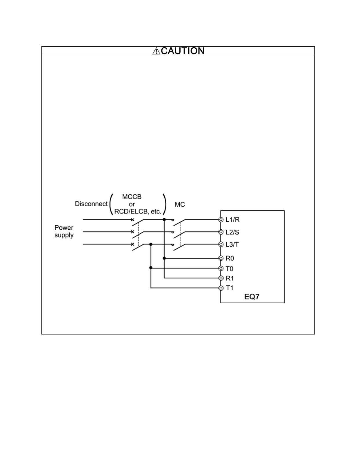
6. All circuits with terminals L1/R, L2/S, L3/T, R0, T0, R1, T1 must have a common disconnect and be connected
to the same pole of the disconnect if the terminals are connected to the power supply.
7. When using the inverter as a UL Enclosed Type (UL TYPE1), purchase Type 1 kit (option) and mount it on the
inverter as instructed.
UL/cUL-listed inverters are subject to the regulations set forth by the UL standards and CSA standards (cULlisted for Canada) by installation within precautions listed below.
viii
Page 10
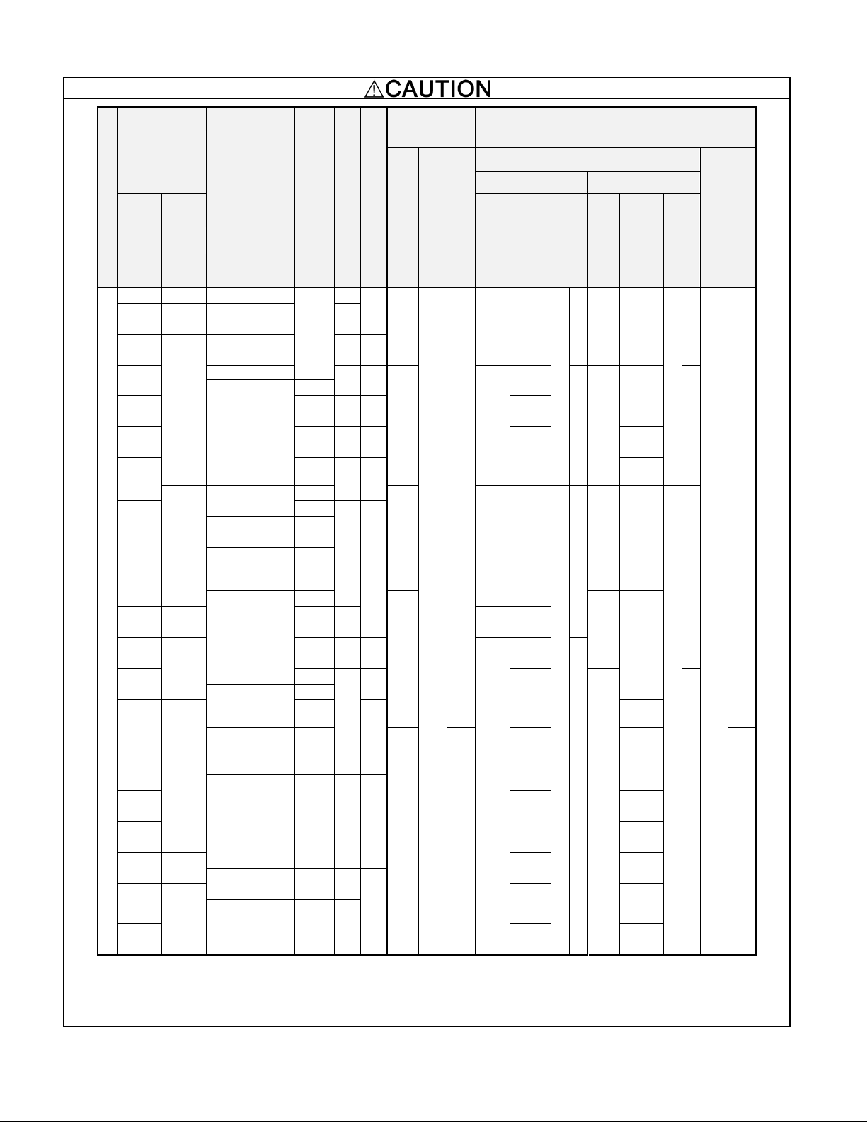
Conformity with UL standards and CSA standards (cUL-listed for Canada) (continued)
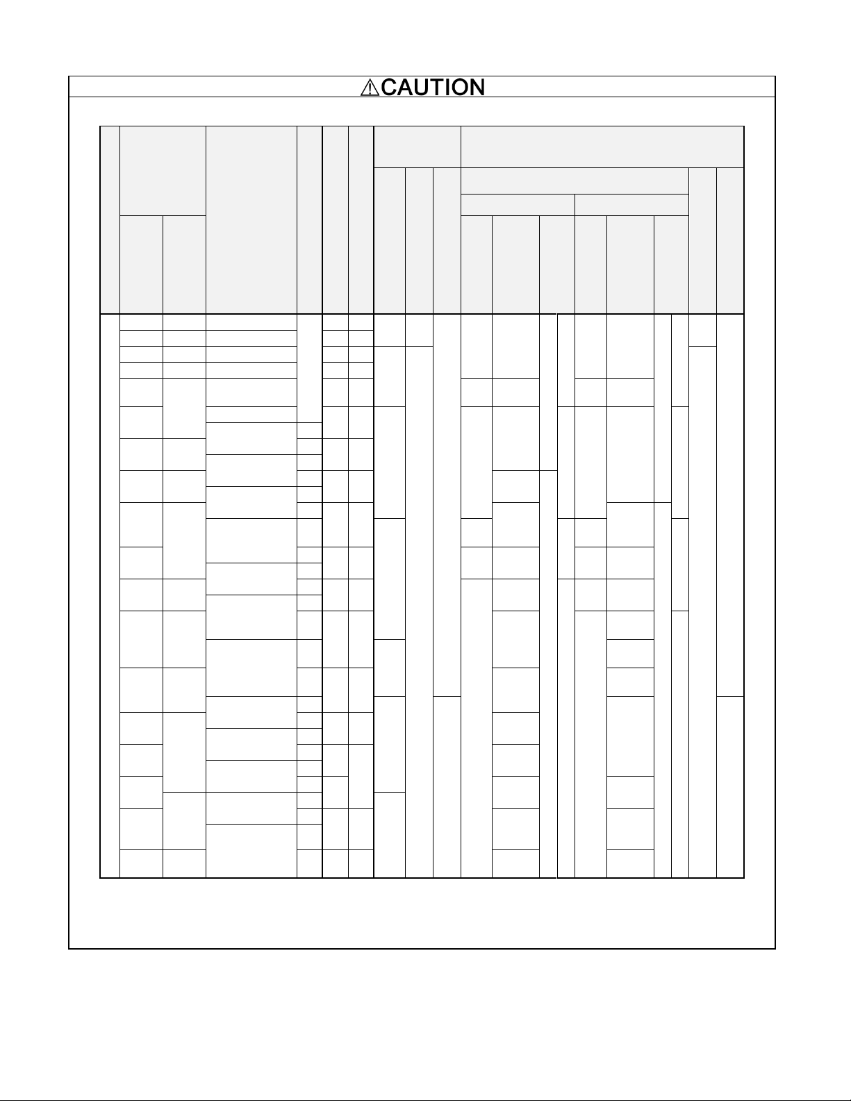
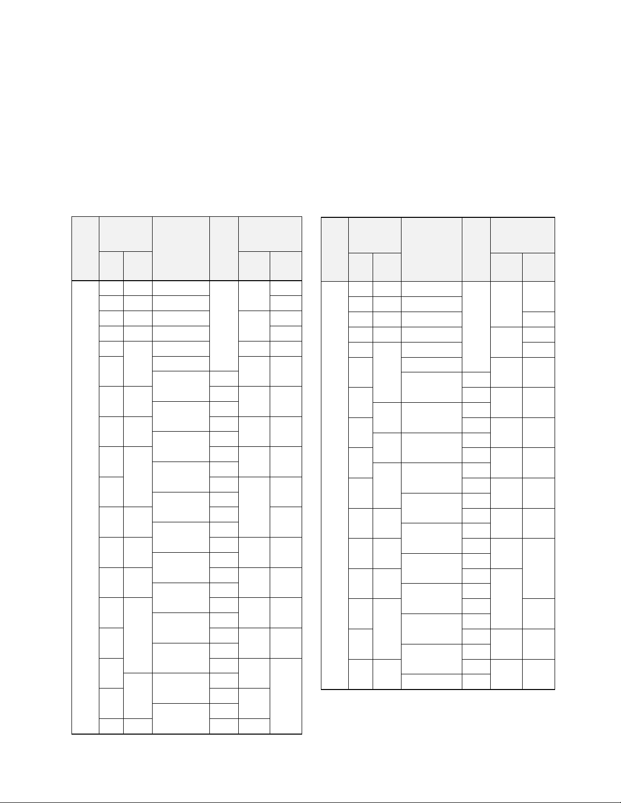
8. Install UL certified fuses or circuit breaker between the power supply and the inverter, referring to the table below.
Power supply voltage
Nominal
applied motor
(HP)
Inverter type
CT/VT mode
Class J fuse size (A)
Circuit breaker trip size (A)
Required
torque
lb-in (Nm)
Wire size
AWG (mm
2
)
Main terminal
Aux. control power
supply
Aux. Fan power supply
Main terminal
Aux. control power
supply
Aux. fan power supply
L1/R, L2/S, L3/T
U, V, W
Three-
phase
Single-
phase
60C (140F)
Cu wire
75C (167F)
Cu wire
Remarks
60C (140F)
Cu wire
75C (167F)
Cu wire
Remarks
230 V
0.5
0.25
EQ7-20P5-C
CT/
VT
10
5
10.6
(1.2)
-
-
14
(2.1)
14
(2.1)
*1
-
14
(2.1)
14
(2.1)
*1
-
-
-
1
0.5
EQ7-2001-C
15
10
2
1
EQ7-2002-C
20
15
15.9
(1.8)
10.6
(1.2)
14
(2.1)
*1
*2
3
1.5
EQ7-2003-C
30
20
5
3
EQ7-2005-C
40
30
10
(5.3)
10
(5.3)
12
(3.3)
12
(3.3)
7.5
EQ7-2007-C
60
50
30.9
(3.5)
-
8
(8.4)
*2
*3
-
8
(8.4)
*2
*3
EQ7-2010-C
CT
10
5
VT
75
75
EQ7-2015-C
CT
15
7.5
VT
100
100
6
(13.3)
-
EQ7-2020-C
CT
20
10
VT
150
125
4
(21.2)
6
(13.3)
-
EQ7-2025-C
CT
51.3
(5.8)
3
(26.7)
-
4
(21.2)
-
25
VT
175
150
1
(42.4)
3
(26.7)
3
(26.7) 4 (21.2)
EQ7-2030-C
CT
30
15
VT
200
175
-
2
(33.6)
*2
*3
2
(33.6) 3 (26.7)
EQ7-2040-C
CT
40
20
VT
250
200
2/0
(67.4)
-
2
(33.6)
*2
*3
EQ7-2050-C
CT
119.4
(13.5)
1
(42.4)
50
25
VT
350
250
3/0
(85)
1/0
(53.5)
EQ7-2060-C
CT
238.9
(27)
10.6
(1.2)
4/0
(107.2)
14
(2.1)
60
30
VT
400
300
4/0
(107.2)
EQ7-2075-C
CT
75
VT
450
350
2/0×2
(67.4×2)
EQ7-2100-C
CT
100
VT
500
3/0×2
(85×2)
3/0×2
(85×2)
40
EQ7-2125-C
CT
424.7
(48)
125
VT
600
400
4/0×2
(107.2×2
)
4/0×2
(107.2×2
)
EQ7-2150-C
CT
150
50
VT
700
500
300×2
(152×2)
300×2
(152×2)
Note 1: Control circuit terminals Tightening torque: 6.1 b-in (0.7 Nm), Recommended wire size: AWG 19 or 18 (0.65 to 0.82 mm2)
*1 No terminal end treatment is required for connection.
*2 Use 75 C (167 F) Cu (Copper) wire only.
*3 The wire size of UL Open Type and Enclosed Type are common. Please contact us if UL Open Type exclusive wire is necessary.
ix
Page 11
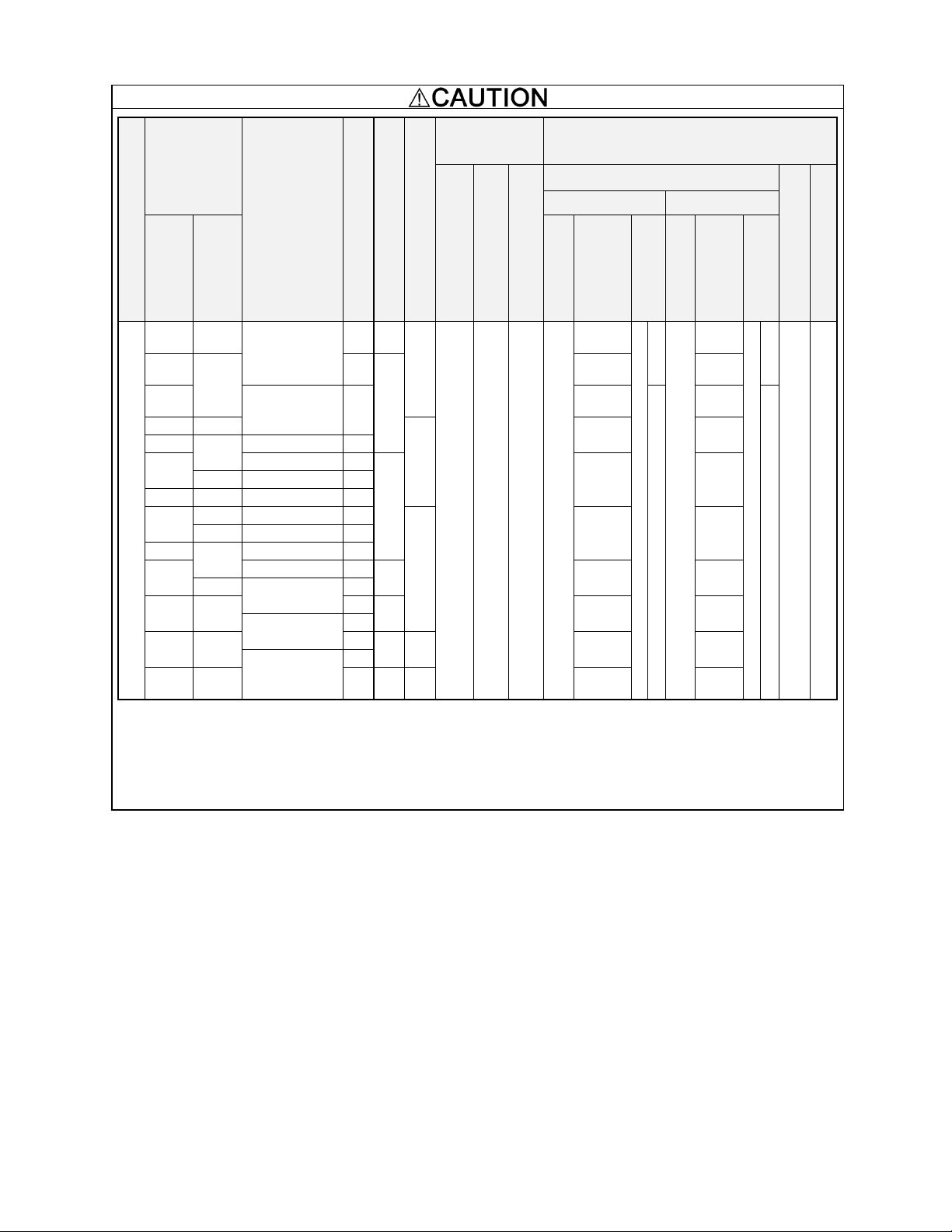
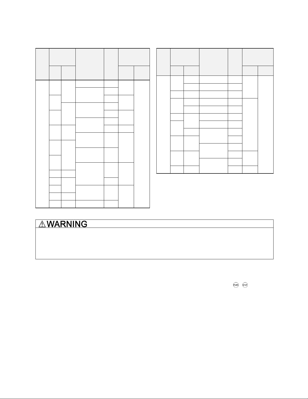
Conformity with UL standards and CSA standards (cUL-listed for Canada) (continued)
Power supply voltage
Nominal applied
motor
(HP)
Inverter type
CT/VT mode
Class J fuse size (A)
Circuit breaker trip size (A)
Required
torque
b-in (Nm)
Wire size
AWG (mm
2
)
Main terminal
Aux. control power supply
Aux. Fan power supply
Main terminal
Aux. control power supply
Aux. fan power supply
L1/R, L2/S, L3/T
U, V, W
Three-
phase
Single-
phase
60 C (140 F)
Cu wire
75 C (167 F)
Cu wire
Remarks
60 C (140 F)
Cu wire
75 C (167 F)
Cu wire
Remarks
460 V
0.5
0.25
EQ7-40P5-C
CT/
VT
3
5
10.6
(1.2)
-
-
14
(2.1)
14
(2.1)
*1
-
14
(2.1)
14
(2.1)
*1
-
-
-
1
0.5
EQ7-4001-C
6
2
1
EQ7-4002-C
10
10
15.9
(1.8)
10.6
(1.2)
14
(2.1)
*1
*2
3
1.5
EQ7-4003-C
15
15
5
3
EQ7-4005-C
20
20
7.5
EQ7-4007-C
30
30
30.9
(3.5)
-
12
(3.3)
*2
*3
-
12
(3.3)
*2
*3
EQ7-4010-C
CT
10
VT
40
40
10
(5.3)
5
EQ7-4015-C
CT
15
VT
60
50
8
(8.4)
10
(5.3)
7.5
EQ7-4020-C
CT
20
VT
70
60
8
(8.4)
10
EQ7-4025-C
CT
51.3
(5.8)
6
(13.3)
6
(13.3)
-
-
6
(13.3)
6
(13.3)
-
-
25
VT
90
75
EQ7-4030-C
CT
30
15
VT
100
100
4
(21.2)
EQ7-4040-C
CT
40
20
VT
125
125
3
(26.7)
4
(21.2)
4
(21.2)
EQ7-4050-C
CT
119.4
(13.5)
2
(33.6)
2
(33.6)
50
25
VT
175
2
(33.6)
3
(26.7)
EQ7-4060-C
CT
60
30
VT
200
150
-
2
(33.6)
*2
*3
EQ7-4075-C
CT
75
VT
250
200
1/0
(53.5)
-
*2
*3
EQ7-4100-C
CT
100
40
VT
175
1/0
(53.5)
EQ7-4125-C
CT
238.9
(27)
10.6
(1.2)
2/0
(67.4)
4/0
(107.2)
14
(2.1)
*1
*2
125
50
VT
300
200
EQ7-4150-C
CT/VT
350
250
150
1/0×2
(53.5×2
)
1/0×2
(53.5×2)
60
EQ7-4200-C
CT/VT
400
300
200
2/0×2
(67.4×2)
EQ7-4250-C
CT/VT
500
350
424.7
(48)
250
75
3/0×2
(85×2)
3/0×2
(85×2)
EQ7-4300-C
CT/VT
600
500
300
100
4/0×2
(107.2×
2)
250×2
(127×2)
EQ7-4350-C
CT/VT
700
350
250×2
(127×2)
300×2
(152×2)
EQ7-4450-C
CT
700
Note 1: Control circuit terminals Tightening torque: 6.1 lb-in (0.7 Nm), Recommended wire size: AWG 19 or 18 (0.65 to 0.82 mm2)
*1 No terminal end treatment is required for connection.
*2 Use 75 C (167 F) Cu (Copper) wire only.
*3 The wire size of UL Open Type and Enclosed Type are common. Please contact us if UL Open Type exclusive wire is necessary.
x
Page 12
Conformity with UL standards and CSA standards (cUL-listed for Canada) (continued)
Power supply voltage
Nominal applied
motor
HP
Inverter type
CT//VT mode
Class J fuse size (A)
Circuit breaker trip size (A)
Required
torque lb-in
(Nm)
Wire size
AWG (mm
2
)
Main terminal
Aux. control power supply
Aux. Fan power supply
Main terminal
Aux. control power supply
Aux. fan power supply
L1/R, L2/S, L3/T
U, V, W
Three-
phase
Single-
phase
60 C (140 F)
Cu wire
75 C (167 F)
Cu wire
Remarks
60 C (140 F)
Cu wire
75 C (167 F)
Cu wire
Remarks
460 V
350
-
EQ7-4450-C
CT
800
600
424.7
(48)
10.6
(1.2)
10.6
(1.2)
-
300×2
(152×2)
-
*2
*3
-
350×2
(177×2)
-
*2
*3
14
(2.1)
*1
*2
14
(2.1)
*1
*2
450
125
VT
1000
400×2
(203×2)
400×2
(203×2)
400
EQ7-4500-C
CT
250×2
(127×2)
*2
*4
300×2
(152×2)
*2
*4
450
-
800
300×2
(152×2)
350×2
(177×2)
-
150
EQ7-4600-C
CT
500
EQ7-4500-C
VT
1200
400×2
(203×2)
400×2
(203×2)
-
EQ7-4600-C
CT - 150
EQ7-4700-C
CT
600
200
EQ7-4600-C
VT
1200
500×2
(253×2)
500×2
(253×2)
-
EQ7-4700-C
CT
-
200
EQ7-4800-C
CT
700
EQ7-4700-C
VT
1400
600×2
(304×2)
600×2
(304×2)
-
EQ7-4800-C
CT
800
250
VT
1600
350×3
(177×3)
400×3
(203×3)
EQ7-4900-C
CT
900
300
VT
2000
1400
500×3
(253×3)
600×3
(304×3)
EQ7-41000-C
CT
1000
400
VT
2200
1600
600×3
(304×3)
500×4
(253×4)
Note: Control circuit terminals Tightening torque: 6.1 lb-in (0.7 Nm), Recommended wire size: AWG 19 or 18 (0.65 to 0.82 mm2)
*1 No terminal end treatment is required for connection.
*2 Use 75 C (167 F) Cu (Copper) wire only.
*3 The wire size of UL Open Type and Enclosed Type are common. Please contact us if UL Open Type exclusive wire is necessary.
*4 It is showing the wire size for UL Open Type.
See additional material INR-SI47-1365-JE for UL Enclosed Type (Pack with TYPE1 kit).
xi
Page 13
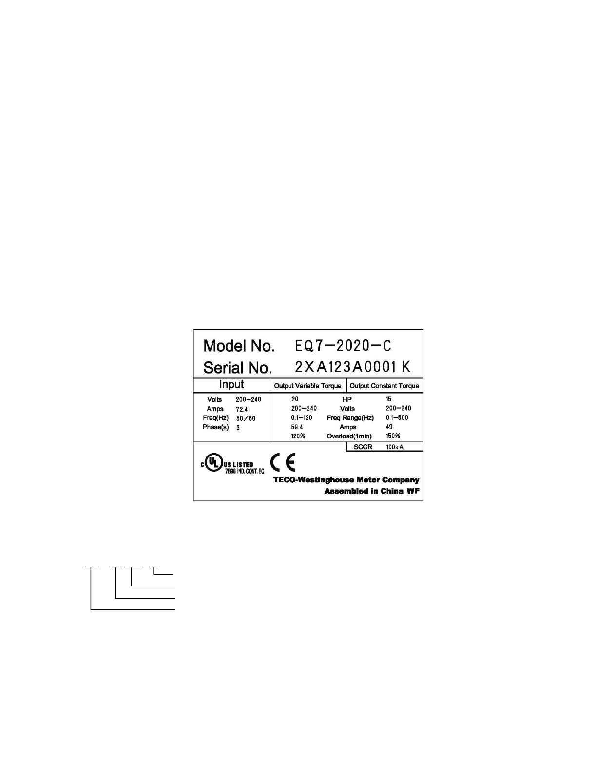
Chapter 1 Drive Model Identification
EQ7 – X XXX - X
C = Chassis; IP20 or IP00
HP Rating (Variable Torque)
2 = 230V, 4 = 460V
Product Type
It is essential to verify the EQ7 drive nameplate and make sure that the EQ7 drive has the correct rating so it can be
used in your application with the proper sized AC motor.
Unpack the EQ7 drive and check the following:
(1) The EQ7 drive and quick start guide (this document) are contained in the package. The EQ7 DRIVE-2100-C /
EQ7 DRIVE-4100-C and higher rated types come with a DC reactor (DCR). Be sure to connect the DCR.
(2) The EQ7 drive has not been damaged during transportation there should be no dents or parts missing.
(3) The EQ7 drive is the type you ordered. You can check the type and specifications on the main nameplate. (Main
and sub nameplates are attached to the EQ7 drive and are located as shown below.)
(4) Check that the input voltage range meets the input power requirements.
(5) Ensure that for variable torque applications the motor rated current matches the variable torque FLA or for
constant torque applications it matches the constant torque FLA. Verify that the output voltage rating on the EQ7
drive label meets the motor requirements (nameplate).
TYPE: Type of inverter
Figure 1.1 Nameplate
1-1
Page 14

1.1 Drive Models Constant Torque (CT) / Variable Torque (VT) HP Ratings
Voltage
EQ7 DRIVE
Variable Torque HP
Constant Torque HP
Frame /
Enclosure
230V
EQ7-20P5-C
0.5
0.5
Plastic
EQ7-2001-C
1 1 Plastic
EQ7-2002-C
2 2 Plastic
EQ7-2003-C
3 3 Plastic
EQ7-2005-C
5 5 Plastic
EQ7-2007-C
7.5
7.5
Plastic
EQ7-2010-C
10
7.5
Plastic
EQ7-2015-C
15
10
Plastic
EQ7-2020-C
20
15
Plastic
EQ7-2025-C
25
20
Plastic
EQ7-2030-C
30
25
Plastic
EQ7-2040-C
40
30
Plastic
EQ7-2050-C
50
40
Sheet Metal
EQ7-2060-C
60
50
Sheet Metal
EQ7-2075-C
75
60
Sheet Metal
EQ7-2100-C
100
75
Sheet Metal
EQ7-2125-C
125
100
Sheet Metal
EQ7-2150-C
150
125
Sheet Metal
460V
EQ7-40P5-C
0.5
0.5
Plastic
EQ7-4001-C
1 1 Plastic
EQ7-4002-C
2 2 Plastic
EQ7-4003-C
3 3 Plastic
EQ7-4005-C
5 5 Plastic
EQ7-4007-C
7.5
7.5
Plastic
EQ7-4010-C
10
7.5
Plastic
EQ7-4015-C
15
10
Plastic
EQ7-4020-C
20
15
Plastic
EQ7-4025-C
25
20
Plastic
EQ7-4030-C
30
25
Plastic
EQ7-4040-C
40
30
Plastic
EQ7-4050-C
50
40
Sheet Metal
EQ7-4060-C
60
50
Sheet Metal
EQ7-4075-C
75
60
Sheet Metal
EQ7-4100-C
100
75
Sheet Metal
EQ7-4125-C
125
100
Sheet Metal
EQ7-4150-C
150
125/150*
Sheet Metal
EQ7-4200-C
200
200*
Sheet Metal
EQ7-4250-C
250
250*
Sheet Metal
EQ7-4300-C
300
300*
Sheet Metal
EQ7-4350-C
350
350*
Sheet Metal
EQ7-4450-C
400/450
350
Sheet Metal
EQ7-4500-C
500
400/450*
Sheet Metal
EQ7-4600-C
600
500*
Sheet Metal
EQ7-4700-C
700
600*
Sheet Metal
EQ7-4800-C
800
700*
Sheet Metal
EQ7-4900-C
900
800
Sheet Metal
EQ7-41000-C
1000
900
Sheet Metal
This table shows the Variable Torque and Constant Torque ratings for all EQ7 drive models.
* The HP ratings marked with (*) are suitable for constant torque V/F Control. Refer to EQ7 Instruction Manual
chapter 11 for constant torque vector control HP ratings.
Table 1.1
1-2
Page 15

1.2 Installation and wiring practices
Environments
Possible problems
Sample measures
Applications
Highly concentrated
sulfurizing gas or
other corrosive gases
Corrosive gases cause parts
inside the inverter to corrode,
resulting in an inverter
malfunction.
Any of the following measures may be
necessary.
-Mount the inverter in a sealed panel
with IP6X or air-purge mechanism.
-Place the panel in a room free from
influence of the gases.
Paper manufacturing, sewage
disposal, sludge treatment,
tire manufacturing, gypsum
manufacturing, metal
processing, and a particular
process in textile factories.
A lot of conductive
dust or foreign
material (e.g., metal
powders or shavings,
carbon fibers, or
carbon dust)
Entry of conductive dust into
the inverter causes a short
circuit.
Any of the following measures may be
necessary.
-Mount the inverter in a sealed panel.
-Place the panel in a room free from
influence of the conductive dust.
Wiredrawing machines, metal
processing, extruding
machines, printing presses,
combustors, and industrial
waste treatment.
A lot of fbrous or
paper dust
Fibrous or paper dust
accumulated on the heat sink
lowers the cooing effect.
Entry of dust into the inverter
causes the electronic circuitry
to malfunction.
Any of the following measures may be
necessary.
-Mount the inverter in a sealed panel
that shuts out dust.
-Ensure a maintenance space for
periodical cleaning of the heat sink in
panel engineering design.
-Employ external cooling when
mounting the inverter in a panel for
easy maintenance and perform
periodical maintenance.
Textile manufacturing and
paper manufacturing.
High humidity or dew
condensation
In an environment where a
humidifier is used or where the
air conditioner is not equipped
with a dehumidifier, high
humidity or dew condensation
results, which causes a shortcircuiting or malfunction of
electronic circuitry inside the
inverter.
- Put a heating module such
as a space heater in the panel.
Outdoor installation.
Film manufacturing line,
pumps and food processing.
V bration or shock
exceeding the
specified level
If a large vibration or shock
exceeding the specified level is
applied to the inverter, for
example, due to a carrier
running on seam joints of rails
or blasting at a construction
site, the inverter structure gets
damaged.
-Insert shock-absorbing materials
between the mounting base of the
inverter and the panel for safe
mounting.
Installation of an inverter
panel on a carrier or selfpropelled machine.
Ventilating fan at a
construction site or a press
machine.
Fumigation for export
packaging
Halogen compounds such as
methyl bromide used in
fumigation corrodes some
parts inside the inverter.
-When exporting an inverter built in a
panel or equipment, pack them in a
previously fumigated wooden crate.
-When packing an inverter alone for
export, use a laminated veneer lumber
(LVL).
Exporting.
Mounting of the EQ7 drive is extremely important for accessibility as well as for the environment. Various EQ7 drive
models are available and the mounting dimensions (footprint) may be different. Install the EQ7 drive in an
environment that satisfies the requirements.
TECO-Westinghouse Motor Company strongly recommends installing inverters in a panel for safety reasons, in
particular, when installing the ones that have an enclosure rating of IP00.
When installing the EQ7 drive in a place out of the specified environmental requirements, it is necessary to derate the
inverter or consider the panel engineering design suitable for the special environment or the panel installation
location. For details consult your TECO-Westinghouse Motor Company representative. The special environments
listed below require using the specially designed panel or considering the panel installation location.
Installation environment
Table 1.2: Installation environment
1-3
Page 16
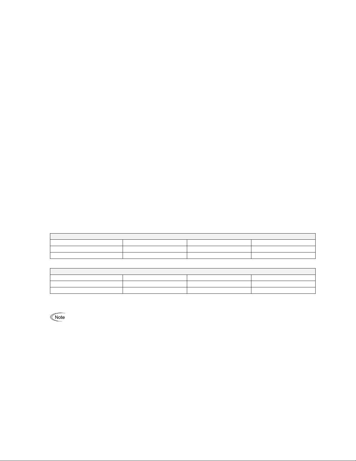
Storage environment
Inverter 7.5 HP and larger
Motor Insulation Level
1000 V
1300 V
1600 V
460 VAC Input Voltage
66 ft (20 m)
328 ft (100 m)
1312 ft (400 m)*
230 VAC Input Voltage
1312 ft (400 m)*
1312 ft (400 m)*
1312 ft (400 m)*
Inverter 5 HP and smaller
Motor Insulation Level
1000 V
1300 V
1600 V
460 VAC Input Voltage
66 ft (20 m)
165 ft (50 m)*
165 ft (50 m)*
230 VAC Input Voltage
328 ft (100 m)*
328 ft (100 m)*
328 ft (100 m)*
• When a motor protective thermal O/L relay is inserted between the inverter and the motor, the thermal
O/L relay may malfunction (particularly in the 460 V series), even when the cable length is 165 ft (50 m) or
less. To correct, insert a filter or reduce the carrier frequency. (Use function code F26 "Motor sound".)
• For the vector control mode, wiring length is 328 ft (100 m) or less.
The storage environment in which the inverter is stored after purchase is different from the operation environment.
For details, refer to the EQ7 DRIVE User's Manual, Chapter 2.
Wiring precautions
(1) Route the wiring of the control circuit terminals as far from the wiring of the main circuit as possible. Otherwise
electric noise may cause malfunctions.
(2) Place the control circuit wires inside the inverter to keep them away from the live parts of the main circuit (such as
the terminal block of the main circuit).
(3) If more than one motor is to be connected to a single inverter, the wiring length should be the sum of the length of
the wires to the motors.
(4) Drive output terminals (U, V, W)
1) Connect these terminals to a 3-phase motor in the correct phase sequence. If the direction of motor rotation is
incorrect, exchange any two of the U, V, and W phases.
2) Do not connect a power factor correction capacitor or surge suppressor to the inverter output.
3) If the cable from the inverter to the motor is very long, a high-frequency current may be generated by stray
capacitance between the cables and result in an overcurrent trip of the inverter, an increase in leakage current,
or a reduction in current indication precision.
When a motor is driven by a PWM-type inverter, the motor terminals may be subject to surge voltage
generated by inverter element switching. If the motor cable (with 460 V series motors, in particular) is particularly
long, surge voltage will deteriorate motor insulation. To prevent this, use the following guidelines:
* For this case the cable length is determined by secondary effects and not voltage spiking.
(5) When an output circuit filter is inserted in the secondary circuit or the wiring between the inverter and the
motor is long, a voltage loss occurs due to reactance of the filter or wiring so that the insufficient voltage may cause
output current oscillation or a lack of motor output torque. To avoid it, select the constant torque load by setting the
function code F37 (Load Selection/Auto Torque Boost/Auto Energy Saving Operation 1) to "1" and keep the inverter
output voltage at a higher level by configuring H50/H52 (Non-linear V/f Pattern, Frequency) and H51/H53 (Non-linear
V/f Pattern, Voltage).
1-4
Page 17

Precautions for connection of peripheral equipment
3)61800 (IEC 67×
(V) voltage average phase-Three
(V) voltage Min - (V) voltageMax
=(%) unbalance Voltage -
DCR models
Input power factor
Remarks
DCR2/4-/A/B
Approx. 90% to 95%
The last letter identifies the capacitance.
DCR2/4-C
Approx. 86% to 90%
Exclusively designed for inverters of 50 HP or above.
For selecting DCR models, refer to Chapter 11 "SPECIFICATIONS."
(1) Phase-advancing capacitors for power factor correction
Do not mount a phase-advancing capacitor for power factor correction in the inverter's input (primary) or output
(secondary) circuit. Mounting it in the input (primary) circuit takes no effect. To correct the inverter power factor,
use an optional DC reactor (DCR). Mounting it in the output (secondary) circuit causes an overcurrent trip,
disabling operation.
An overvoltage trip that occurs when the inverter is stopped or running with a light load is assumed to be due to
surge current generated by open/close of phase-advancing capacitors in the power system. An optional DC/AC
reactor (DCR/ACR) is recommended as a measure to be taken at the inverter side.
Input current to an inverter contains a harmonic component that may affect other motors and phase-advancing
capacitors on the same power supply line. If the harmonic component causes any problems, connect an optional
DCR/ACR to the inverter. In some cases, it is necessary to insert a reactor in series with the phase-advancing
capacitors.
(2) Power supply lines (Application of a DC/AC reactor)
Use an optional DC reactor (DCR) when the capacity of the power supply transformer is 500 kVA or more and is
10 times or more the inverter rated capacity or when there are thyristor-driven loads. If no DCR is used, the
percentage-reactance of the power supply decreases, and harmonic components and their peak levels increase.
These factors may break rectifiers or capacitors in the converter section of the inverter, or decrease the
capacitance of the capacitors.
If the input voltage unbalance rate is 2% to 3%, use an optional AC reactor (ACR).
(3) DC reactor (DCR) for correcting the inverter input power factor (for suppressing harmonics)
To correct the inverter input power factor (to suppress harmonics), use an optional DCR. Using a DCR increases
the reactance of inverter’s power source so as to decrease harmonic components on the power source lines and
correct the power factor of the inverter.
(4) PWM converter for correcting the inverter input power factor
Using a PWM converter (High power-factor, regenerative PWM converter) corrects the inverter power factor up to
nearly 100%. When combining an inverter with a PWM converter, disable the main power down detection by
setting the function code H72 to "0." If the main power loss detection is enabled (H72 = 1 by factory default), the
inverter interprets the main power as being shut down, ignoring an entry of a run command.
1-5
Page 18
(5) Molded case circuit breaker (MCCB) or residual-current-operated protective device (RCD)/earth leakage circuit
Power
supply
voltage
Nominal
applied
motor
(HP)
Inverter type
CT/VT
mode
Rated current of
MCCB and
RCD/ELCB (A)
Three
-
phase
Single-
phase
w/ DCR
w/o
DCR
230 V
0.5
0.25
EQ7-20P5-C
CT/VT
5
5
1
0.5
EQ7-2001-C
10 2 1
EQ7-2002-C
10
15 3 1.5
EQ7-2003-C
20
5
3
EQ7-2005-C
20
30
7.5
EQ7-2007-C
30
50
EQ7-2010-C
CT
10
5
VT
40
75
EQ7-2015-C
CT
15
7.5
VT
50
100
EQ7-2020-C
CT
20
10
VT
75
125
EQ7-2025-C
CT
25
VT
100
150
EQ7-2030-C
CT
30
15
VT
175
EQ7-2040-C
CT
40
20
VT
150
200
EQ7-2050-C
CT
50
25
VT
175
250
EQ7-2060-C
CT
60
30
VT
200
300
EQ7-2075-C
CT
75
VT
250
350
EQ7-2100-C
CT
100
VT
350
--
40
EQ7-2125-C
CT
125
VT
400
EQ7-2150-C
CT
150
50
VT
350
Power
supply
voltage
Nominal
applied
motor
(HP)
Inverter type
CT/VT
mode
Rated current of
MCCB and
RCD/ELCB (A)
Three
-
phase
Single-
phase
w/ DCR
w/o
DCR
460 V
0.5
0.25
EQ7-40P5-C
CT/VT
5
5
1
0.5
EQ7-4001-C
2
1
EQ7-4002-C
10 3 1.5
EQ7-4003-C
10
15
5 3 EQ7-4005-C
20
7.5
EQ7-4007-C
15
30
EQ7-4010-C
CT
10
VT
20
40
5
EQ7-4015-C
CT
15
VT
30
50
7.5
EQ7-4020-C
CT
20
VT
40
60
10
EQ7-4025-C
CT
25
VT
40
75
EQ7-4030-C
CT
30
15
VT
50
100
EQ7-4040-C
CT
40
20
VT
75
125
EQ7-4050-C
CT
50
25
VT
100
EQ7-4060-C
CT
60
30
VT
150
EQ7-4075-C
CT
75
VT
125
200
EQ7-4100-C
CT
100
40
VT
175
--
EQ7-4125-C
CT
breaker (ELCB)
Install a recommended MCCB or RCD/ELCB (with overcurrent protection) in the primary circuit of the inverter to
protect the wiring. Since using an MCCB or RCD/ELCB with a lager capacity than recommended ones breaks the
protective coordination of the power supply system, be sure to select recommended ones. Also select ones with
short-circuit breaking capacity suitable for the power source impedance.
Molded Case Circuit Breaker (MCCB) and Residual-Current-Operated Protective Device (RCD)/Earth Leakage
Circuit Breaker (ELCB)
1-6
Page 19
Molded Case Circuit Breaker (MCCB) and Residual-
Power
supply
voltage
Nominal
applied
motor
(HP)
Inverter type
CT/VT
mode
Rated current of
MCCB and
RCD/ELCB (A)
Three
-
phase
Single-
phase
w/ DCR
w/o
DCR
460 V
125
50
EQ7-4125-C
VT
200
--
EQ7-4150-C
CT
150
CT/VT
250
60
EQ7-4200-C
CT
200
CT/VT
300
EQ7-4250-C
CT
250
75
CT/VT
350
EQ7-4300-C
CT/VT
500
300
100
EQ7-4350-C
CT/VT
350
EQ7-4450-C
CT
600
350
-
450
125
VT
400
EQ7-4500-C
CT
800
450
-
-
150
EQ7-4600-C
CT
Power
supply
voltage
Nominal
applied
motor
(HP)
Inverter type
CT/VT
mode
Rated current of
MCCB and
RCD/ELCB (A)
Three-
phase
Single-
phase
w/ DCR
w/o
DCR
460 V
500
150
EQ7-4500-C
VT
800
--
-
EQ7-4600-C
CT - 150
EQ7-4700-C
CT
600
200
EQ7-4600-C
VT
1200
-
EQ7-4700-C
CT
-
200
EQ7-4800-C
CT
700
EQ7-4700-C
VT
-
EQ7-4800-C
CT
800
250
VT
EQ7-4900-C
CT
900
300
VT
1400
EQ7-41000-C
CT
1000
400
VT
1600
If no zero-phase current (earth leakage current) detective device such as a ground-fault relay is installed in the
upstream power supply line in order to avoid the entire power supply system's shutdown undesirable to factory
operation, install a residual-current-operated protective device (RCD)/earth leakage circuit breaker (ELCB)
individually to inverters to break the individual inverter power supply lines only.
Otherwise, a fire could occur.
Current-Operated Protective Device (RCD)/Earth
Leakage Circuit Breaker (ELCB)
(6) Magnetic contactor (MC) in the inverter input (primary) circuit
Avoid frequent ON/OFF operation of the magnetic contactor (MC) in the input circuit; otherwise, the inverter failure
may result. If frequent start/stop of the motor is required, use FWD/REV terminal signals or the / keys on the
inverter's keypad.
The frequency of the MC's ON/OFF should not be more than once per 30 minutes. To assure 10 -year or longer
service life of the inverter, it should not be more than once per hour.
1-7
Page 20

• From the system's safety point of view, it is recommended to employ such a sequence that shuts down
the magnetic contactor (MC) in the inverter input circuit with an alarm output signal ALM issued on
inverter's programmable output terminals. The sequence minimizes the secondary damage even if the
inverter breaks.
When the sequence is employed, connecting the MC's primary power line to the inverter's auxiliary
control power input makes it possible to monitor the inverter's alarm status on the keypad.
• The breakdown of a braking unit or misconnection of an external braking resistor may trigger that of the
inverter's internal parts (e.g., charging resistor). To avoid such a breakdown linkage, introduce an MC
and configure a sequence that shuts down the MC if a DC link voltage establishment signal is not
issued within three seconds after the MC is switched on.
For the braking transistor built-in type of inverters, assign a transistor error output signal DBAL on
inverter's programmable output terminals to switch off the MC in the input circuit.
(7) Magnetic contactor (MC) in the inverter output (secondary) circuit
If a magnetic contactor (MC) is inserted in the inverter's output (secondary) circuit for switching the motor to a
commercial power or for any other purposes, it should be switched on and off when both the inverter and motor
are completely stopped. This prevents the contact point from getting rough due to a switching arc of the MC. The
MC should not be equipped with any main circuit surge killer.
Applying a commercial power to the inverter's output circuit breaks the inverter. To avoid it, interlock the MC on the
motor's commercial power line with the one in the inverter output circuit so that they are not switched ON at the
same time.
(8) Surge absorber/surge killer
Do not install any surge absorber or surge killer in the inverter's output (secondary) lines.
Noise reduction
If noise generated from the inverter affects other devices, or that generated from peripheral equipment causes the
inverter to malfunction, follow the basic measures outlined below.
(1) If noise generated from the inverter affects the other devices through power wires or grounding wires:
- Isolate the grounding terminals of the inverter from those of the other devices.
- Connect a noise filter to the inverter power wires.
- Isolate the power system of the other devices from that of the inverter with an insulated transformer.
- Decrease the inverter's carrier frequency (F26).
1-8
Page 21

(2) If induction or radio noise generated from the inverter affects other devices:
Problem
Measures
An earth leakage circuit
breaker* that is
connected to the input
(primary) side has
tripped.
*With overcurrent
protection
1) Decrease the carrier frequency.
2) Make the wires between the inverter and motor shorter.
3) Use an earth leakage circuit breaker with lower sensitivity than the one currently
used.
4) Use an earth leakage circuit breaker that features measures against the high
frequency current component.
An external thermal relay
was activated.
1) Decrease the carrier frequency.
2) Increase the current setting of the thermal relay.
3) Use the electronic thermal overload protection built in the inverter, instead of the
external thermal relay.
- Isolate the main circuit wires from the control circuit wires and other device wires.
- Put the main circuit wires through a metal conduit pipe, and connect the pipe to the ground near the inverter.
- Install the inverter into the metal panel and connect the whole panel to the ground.
- Connect a noise filter to the inverter's power wires.
- Decrease the inverter's carrier frequency (F26).
(3) When implementing measures against noise generated from peripheral equipment:
- For inverter's control signal wires, use twisted or shielded-twisted wires. When using shielded-twisted wires,
connect the shield of the shielded wires to the common terminals of the control circuit.
- Connect a surge absorber in parallel with magnetic contactor's coils or other solenoids (if any).
Leakage current
A high frequency current component generated by insulated gate bipolar transistors (IGBTs) switching on/off inside the
inverter becomes leakage current through stray capacitance of inverter input and output wires or a motor. If any of the
problems listed below occurs, take an appropriate measure against them.
Selecting inverter capacity
(1) To drive a general-purpose motor, select an inverter according to the nominal applied motor rating listed in the
standard specifications table. When high starting torque is required or quick acceleration or deceleration is
required, select an inverter with one rank higher capacity than the standard.
(2) Special motors may have larger rated current than general-purpose ones. In such a case, select an inverter that
meets the following condition.
Inverter rated current > Motor rated current
1-9
Page 22

1.3 Precautions in running inverters
Precautions for running inverters to drive motors or motor-driven machinery are described below.
Motor temperature
When an inverter is used to run a general-purpose motor, the motor temperature becomes higher than when it is
operated with a commercial power supply. In the low-speed range, the motor cooling effect will be weakened, so
decrease the output torque of the motor when running the inverter in the low-speed range.
Motor noise
When a general-purpose motor is driven by an inverter, the noise level is higher than that when it is driven by a
commercial power supply. To reduce noise, raise carrier frequency of the inverter. Operation at 60 Hz or higher can
also result in higher noise level.
Machine vibration
When an inverter-driven motor is mounted to a machine, resonance may be caused by the natural frequencies of the
motor-driven machinery. Driving a 2-pole motor at 60 Hz or higher may cause abnormal vibration. If it happens, do any
of the following:
- Consider the use of a rubber coupling or vibration-proof rubber.
- Use the inverter's jump frequency control feature to skip the resonance frequency zone(s).
- Use the vibration suppression related function codes that may be effective. For details, refer to the description of
H80 in Chapter 4 "FUNCTION CODES" of the user manual.
1.4 Precautions in using special motors
When using special motors, please read the following section:
Explosion-proof motors
When driving an explosion-proof motor with an inverter, use a combination of a motor and an inverter that has been
approved in advance.
Submersible motors and pumps
These motors have a larger rated current than general-purpose motors. Select an inverter with rated output current
that is greater than that of the motor. These motors differ from general-purpose motors in thermal characteristics.
Decrease the thermal time constant of the electronic thermal overload protection to match the motor rating.
Brake motors
For motors equipped with parallel-connected brakes, their power supply for braking must be supplied from the inverter
input (primary) circuit. If the power supply for braking is mistakenly connected to the inverter's output (secondary)
circuit, the brake may not work when the inverter output is shut down. Do not use inverters for driving motors
equipped with series-connected brakes.
Geared motors
If the power transmission mechanism uses an oil-lubricated gearbox or speed changer/reducer, then continuous
operation at low speed may cause poor lubrication. Avoid such operation.
Synchronous motors
It is necessary to take special measures suitable for this motor type. Contact your TECO-Westinghouse Motor
Company representative for details.
Single-phase motors
Single-phase motors are not suitable for inverter-driven variable speed operation.
1-10
Page 23

High-speed motors
If the reference frequency is set to 120 Hz or higher to drive a high-speed motor, test-run the combination of the
inverter and motor beforehand to check it for the safe operation.
Precautions for use on single-phase power
An inverter is a device that converts alternating current of the input line to direct current via the ac-to-dc rectifier and
then converts it to alternating current via the dc-to-ac switching inverter circuit in order to output the required
alternating current. The EQ7 drive is designed to connect to the three-phase power and this manual stipulates the
specifications for the use on the three-phase power.
If the inverter designed for connection to three-phase power runs on single-phase power, ripples (voltage fluctuation)
on the DC link bus voltage rectified from the input power become larger than those in the inverter running on threephase power. The DC-voltage ripple affects the inverter output; that is, ripples could be superimposed on the output
voltage or current, making control hard.
Accordingly, the inverter may not work in full performance or function correctly. To use the EQ7 drive on single-phase
power, therefore, you need to take the following into account.
Output current
Select the inverter capacity to keep the output current within the specified level, referring to chapter 11. Output current
exceeding the limit extremely increases voltage ripples on the DC link bus, impeding normal operation or resulting in
an inverter breakdown.
Wiring
When connecting 230 V inverters of 60 HP or above or 460 V ones of 125 HP or above to single-phase power, use L1
and L3 phases since cooling fans and magnetic contactors inside the inverter are supplied with power via L1 and L3.
Using L2 does not work cooling fans or magnetic contactors, causing abnormal heat, in the worst case, resulting in an
inverter breakdown.
Connecting peripheral devices
For the specifications of circuit breakers and fuses to apply, refer to pages 1-6 and 1-7.
Configuring function codes
(1) Cancel the input phase loss protection of the protection/maintenance function with function code H98 (Bit 1 = 0).
This is because the inverter judges single-phase power as a phase loss.
(2) Limit the drive mode to the VT / CT-V mode (Function code F80 = 0 or 1).
(3) Do not use "Vector control without speed sensor" or torque control. (Function codes F42 5, H18 = 0)
(4) "V/f control with slip compensation inactive" is recommended (F42 = 0). Any other drive control calculates the
motor model using the motor parameters inside the inverter. As ripples on the DC link bus voltage become larger,
therefore, calculation causes some errors so that the inverter may not provide the desired performance. Consider
this problem before use. In particular, when using "Vector control with speed sensor" (F42 = 6), dancer control
(J01 = 3), or brake signals (J68, J69, J70, etc.), assure the operation and safety of those speed sensors.
1-11
Page 24
Item
Specifications
Site location
Indoors
Surrounding/ambient
temperature
-10 to +50 C (14 to 122 F) (Note 1)
Relative humidity
5 to 95% (No condensation)
Atmosphere
The inverter must not be exposed to dust, direct sunlight,
corrosive gases, flammable gases, oil mist, vapor or water drops.
Pollution degree 2 (IEC60664-1) (Note 2)
The atmosphere can contain a small amount of salt.
(0.01 mg/cm2 or less per year)
The inverter must not be subjected to sudden changes in
temperature that will cause condensation to form.
Altitude
3300 ft (1000 m) max. (Note 3)
Atmospheric
pressure
86 to 106 kPa
Vibration
Inverters of
100 HP or below (230 V series)
125 HP or below (460 V series)
Inverters of
125 HP or above (230 V series)
150 HP or above (460 V series)
0.12 inch (3 mm)
(Max. amplitude)
0.12 inch (3 mm)
(Max. amplitude)
2 to less than 9 Hz
2 to less than 9 Hz
9.8 m/s2
9 to less than 20 Hz
2 m/s2
9 to less than 55 Hz
2 m/s2
20 to less than 55 Hz
1 m/s2
55 to less than 200 Hz
1 m/s2
55 to less than 200 Hz
Install the inverter on a base made of metal or other non-flammable material.
Install the inverter on a base made of metal or other non-flammable material.
Otherwise, a fire could occur.
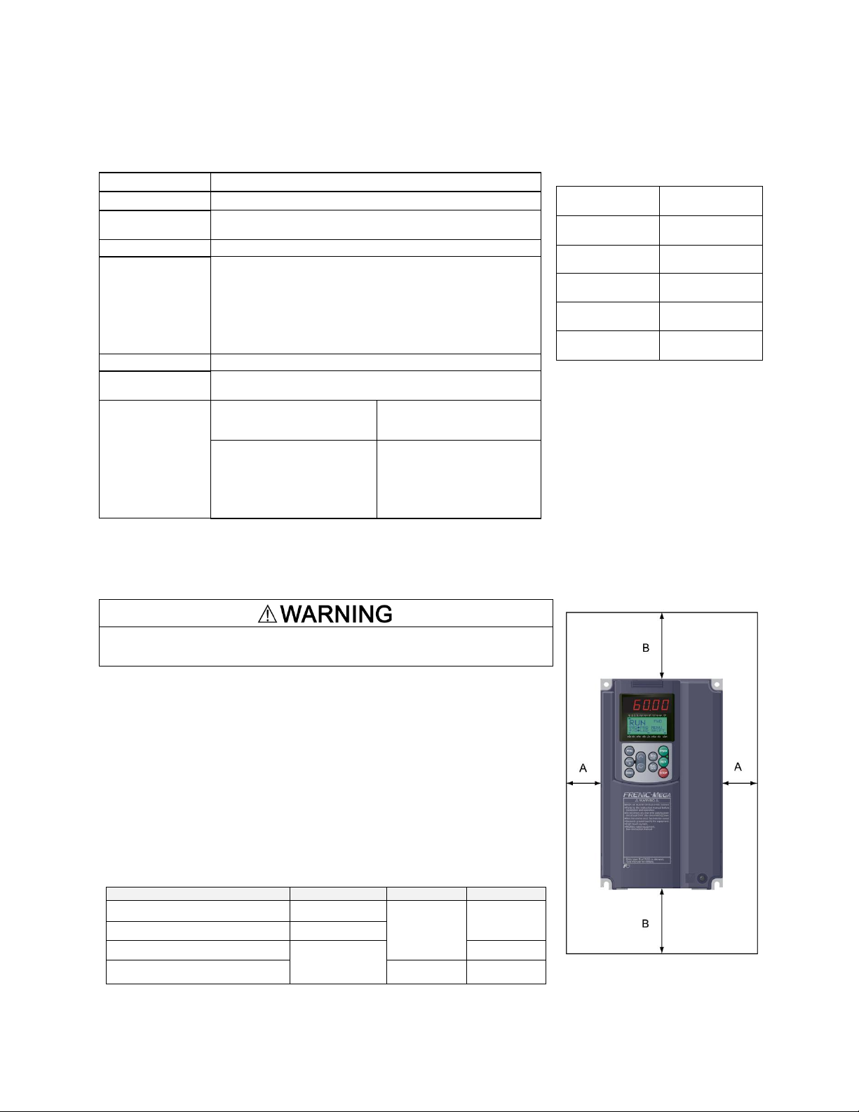
(2) Clearances
Ensure that the minimum clearances indicated in Figure 2.1 and Table 2.3 are
maintained at all times. When mounting the inverter in the panel of your system,
take extra care with ventilation inside the panel as the surrounding temperature
easily rises. Do not mount the inverter in a small panel with poor ventilation.
When mounting two or more inverters
When mounting two or more inverters in the same unit or panel, install them side
by side. When one must be mounted above the other, be sure to separate them
with a partition plate, or the like, so that any heat radiating from an inverter will not
affect the one/s above.
As long as the surrounding temperature is 40°C (104°F) or lower, inverters of 40
HP or below can be mounted side by side without any clearance between them.
Table 2.3 Clearances
inch (mm)
Inverter capacity
A B C
0.5 to 2 HP
2.0 (50)
3.9 (100)
0
3 to 40 HP
0.39 (10)
50 to 450 HP
2.0 (50)
3.9 (100)
500 to 1000 HP
5.9 (150)
5.9 (150)
C: Space required in front of the inverter unit
Table 2.2 Output Current Derating
Factor in Relation to Altitude
Altitude
Output current
derating factor
3300 ft (1000 m)
or lower
1.00
3300 to 4900 ft
(1000 to 1500 m)
0.97
4900 to 6600 ft
(1500 to 2000 m)
0.95
6600 to 8200 ft
(2000 to 2500 m)
0.91
8200 to 9800 ft
(2500 to 3000 m)
0.88
(Note 1) When inverters (40 HP or
below) are mounted side-by-side without
any clearance between them, the
surrounding temperature should be within
the range from -10 to +40 C (14 to 104 F).
This specification also applies to the
inverters (40 HP) equipped with a NEMA1
kit.
(Note 2) Do not install the inverter in an
environment where it may be exposed to
lint, cotton waste or moist dust or dirt
which will clog the heat sink of the
inverter. If the inverter is to be used in
such an environment, install it in a
dustproof panel.
(Note 3) If you use the inverter in an
altitude above 3300 ft (1000 m), you
should apply an output current derating
factor as listed in Table 2.2.
Figure 2.1 Mounting Direction and
Required Clearances
Chapter 2 Mounting and Wiring the Inverter
2.1 Operating Environment
Install the inverter in an environment that satisfies the requirements listed in Table 2.1.
Table 2.1 Environmental Requirements
2.2 Installing the Inverter
(1) Mounting base
2-1
Page 25
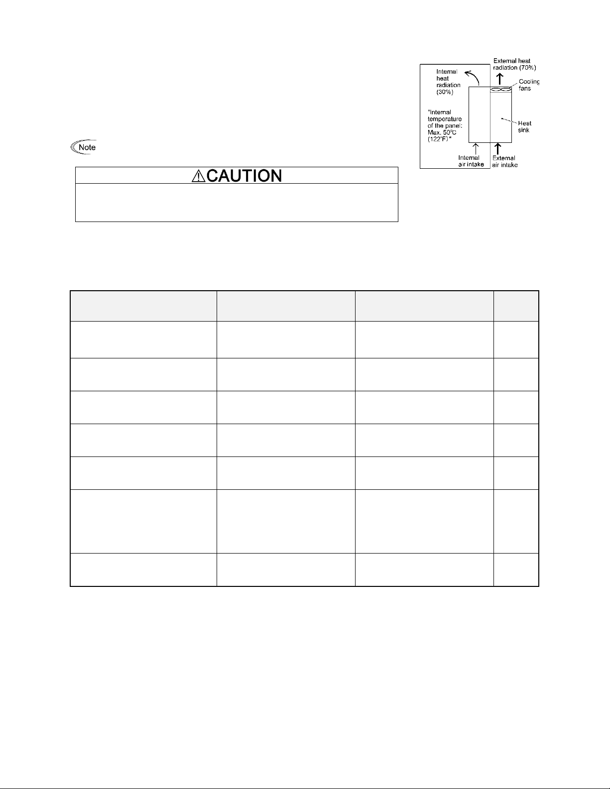
When employing external cooling
In external cooling, the heat sink, which dissipates about 70% of the total heat (total
loss) generated into air, is situated outside the equipment or the panel. The external
cooling, therefore, significantly reduces heat radiating inside the equipment or panel.
To employ external cooling for inverters (except DCR built-in type) of 40 HP or below,
use the mounting adapter for external cooling (option); for those of 50 HP or above,
simply change the positions of the mounting bases.
The DCR built-in type of 40 HP or below cannot employ external cooling.
Prevent lint, paper fibers, sawdust, dust, metallic chips, or other foreign
materials from getting into the inverter or from accumulating on the heat sink.
Otherwise, a fire or accident could occur.
Figure 2.2 External Cooling
Inverter type
Base fixing screw
(Screw size and q'ty)
Case fixing screw
(Screw size and q'ty)
Tightening
torque
lb-in (Nm)
EQ7-2050-C /EQ7-2060-C
EQ7-4050-C
EQ7-4100-C
M6 20
5 pcs for upper side,
3 pcs for lower side
M6 20
2 pcs for upper side
51.3
(5.8)
EQ7-2075-C / EQ7-4100-C
EQ7-4125-C
M6 20
3 pcs each for upper and lower
sides
M6 12
3 pcs for upper side
51.3
(5.8)
EQ7-2125-C
EQ7-4150-C / EQ7-4200-C
M5 12
7 pcs each for upper and lower
sides
M5 12
7 pcs for upper side
31.0
(3.5)
EQ7-4250-C / EQ7-4300-C
M5 16
7 pcs each for upper and lower
sides
M5 16
7 pcs for upper side
31.0
(3.5)
EQ7-2150-C
EQ7-4350-C / EQ7-4450-C
M5 16
8 pcs each for upper and lower
sides
M5 16
8 pcs for upper side
31.0
(3.5)
EQ7-4500-C / EQ7-4600-C
EQ7-4700-C / EQ7-4800-C
M5 16
2 pcs each for upper and lower
sides
M6 20
6 pcs each for upper and lower
sides
M5 16
2 pcs each for upper and lower
sides
M6 20
6 pcs each for upper and lower
sides
31.0
(3.5)
51.3
(5.8)
EQ7-4900-C / EQ7-41000-C
M8 20
8 pcs each for upper and lower
sides
M8 20
8 pcs each for upper and lower
sides
119
(13.5)
To utilize external cooling for inverters of 50 HP or above, change the positions of the top and bottom mounting bases
from the edge to the center of the inverter as shown in Figure 2.3.
Screws differ in size and count for each inverter. Refer to the table below.
Table 2.4 Screw Size, Count and Tightening Torque
1) Remove all base fixing screws and case fixing screws from the top of the inverter.
2) Move the top mounting base to the center of the inverter and secure it to the case fixing screw holes with the base
fixing screws. (After changing the position of the top mounting base, some screws may be left unused.)
3) Remove the base fixing screws from the bottom of the inverter, move the bottom mounting base to the center of the
inverter, and secure it with the base fixing screws, just as in step 2). (Inverters of 450 HP or below have no case
fixing screws on the bottom.)
2-2
Page 26
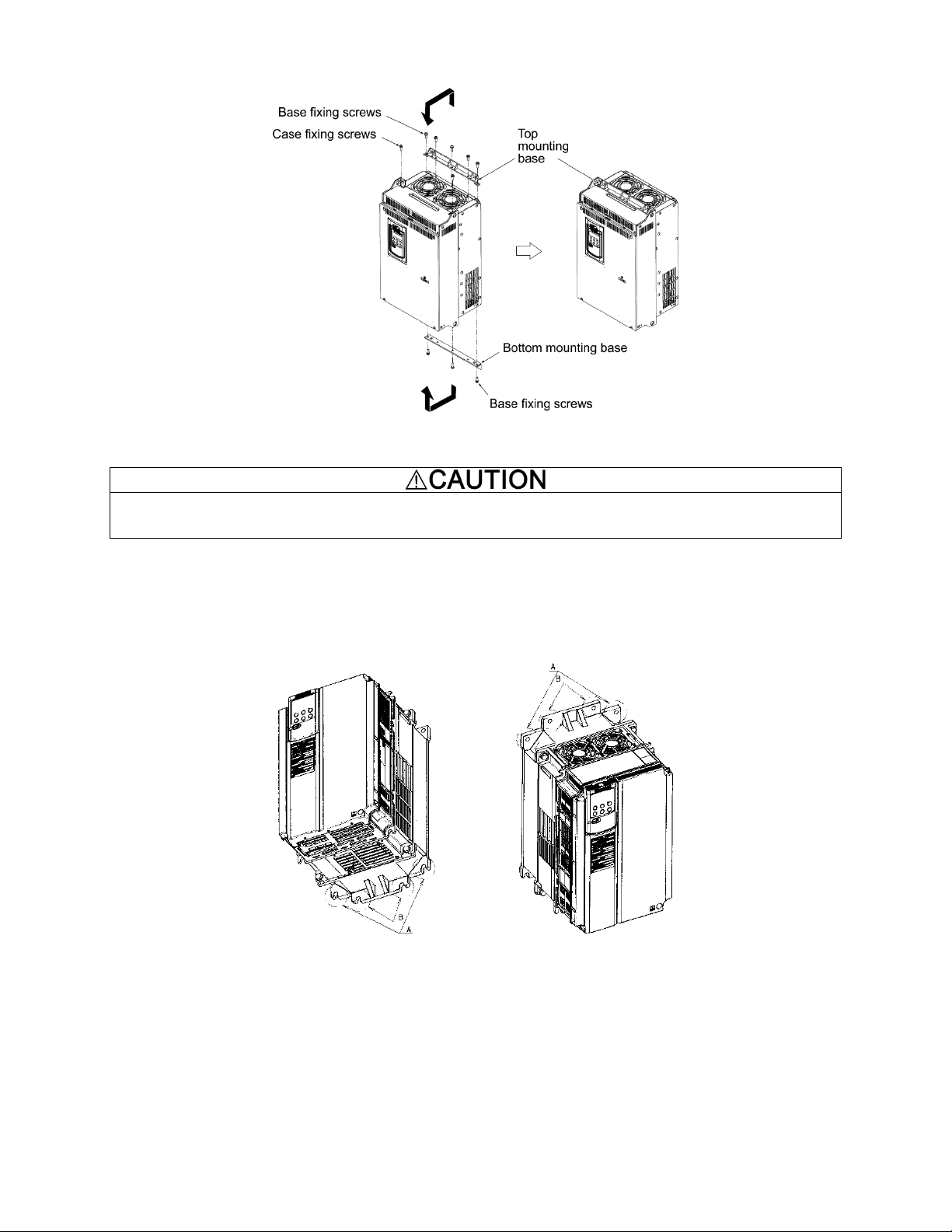
When changing the positions of the top and bottom mounting bases, use only the specified screws.
Otherwise, a fire or accident could occur.
Figure 2.3 Changing the Positions of the Top and Bottom Mounting Bases
(3) Mounting notes
The EQ7-2007-C / EQ7-4007-C through EQ7-2040-C / EQ7-4040-C should be mounted with four screws or bolts using
screw holes A or B shown below. Note that, at each of the top and bottom of the inverter, the two screws or bolts should
be located in a bilaterally symmetrical position.
2-3
Page 27
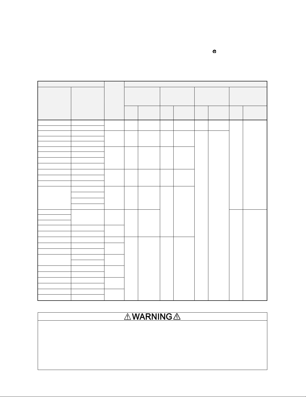
To expose the control printed circuit board (control PCB), open the keypad enclosure.
2.3 Wiring
Follow the procedure below. (In the following description, the inverter has already been installed.)
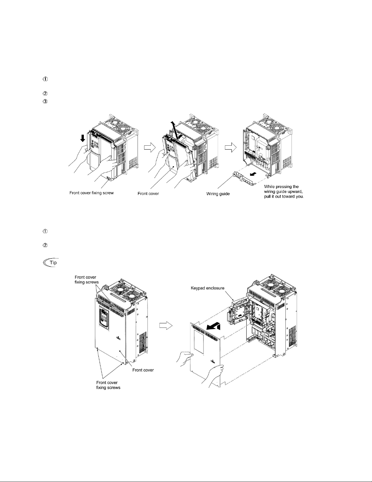
2.3.1 Removing and mounting the front cover and the wiring guide
(1) For inverters of 40 HP or below
First loosen the front cover fixing screw, slide the cover downward holding both sides, tilt it forward, and then pull it
upward, as shown below.
While pressing the wiring guide upward, pull it out and forward.
After carrying out wiring (see Sections 2.3.2 through 2.3.6), put the wiring guide and the front cover back into place
in the reverse order of removal.
Figure 2.4 Removing the Front Cover and the Wiring Guide (e.g EQ7-4020-C)
(2) For inverters of 50 to 1000 HP
Loosen the four front cover fixing screws, hold the cover with both hands, slide it upward slightly, and pull it forward,
as shown below.
After carrying out wiring (see Sections 2.3.2 through 2.3.6), align the screw holes provided in the front cover with the
screws on the inverter case, and then put the front cover back into place in the reverse order of removal.
Figure 2.5 Removing the Front Cover (e.g. EQ7-4050-C)
2-4
Tightening torque: 15.9 lb-in (1.8 Nm) (M4)
31.0 lb-in (3.5 Nm) (M5)
Page 28
Inverter type
Refer to:
Screw specifications
Three-phase
230 V
Three-phase
460 V
Main circuit
terminals
Grounding
terminals
Auxiliary control
power input
terminals
[R0, T0]
Auxiliary fan
power input
terminals
[R1, T1]
Screw
size
Tightening
torque
lb-in (N·m)
Screw
size
Tightening
torque
lb-in (N·m)
Screw
size
Tightening
torque
b-in (N·m)
Screw
size
Tightening
torque
lb-in (N·m)
EQ7-20P5-C
EQ7-40P5-C
Figure A
M3.5
10.6 (1.2)
M3.5
10.6 (1.2)
--
--
--
--
EQ7-2001-C
EQ7-4001-C
EQ7-2002-C
EQ7-4002-C
Figure B
M4
15.9 (1.8)
M4
15.9 (1.8)
M3.5
10.6 (1.2)
EQ7-2003-C
EQ7-4003-C
EQ7-2005-C
EQ7-4005-C
EQ7-2007-C
EQ7-4007-C
Figure C
M5
31.0 (3.5)
M5
31.0 (3.5)
EQ7-2010-C
EQ7-4010-C
EQ7-2015-C
EQ7-4015-C
EQ7-2020-C
EQ7-4010-C
EQ7-2025-C
EQ7-4025-C
Figure D
M6
51.3 (5.8)
M6
51.3 (5.8)
EQ7-2030-C
EQ7-4030-C
EQ7-2040-C
EQ7-4040-C
EQ7-2050-C
EQ7-4050-C
Figure E
M8
119 (13.5)
M8
119 (13.5)
EQ7-4060-C
EQ7-4075-C
EQ7-4100-C
EQ7-2060-C
EQ7-4125-C
Figure F
M10
239 (27)
M3.5
10.6 (1.2)
EQ7-2075-C
EQ7-2100-C
--
EQ7-4150-C
Figure G
--
EQ7-4200-C
EQ7-2125-C
--
Figure M
M12
425 (48)
M10
239 (27)
--
EQ7-4250-C
Figure H
--
EQ7-4300-C
EQ7-2150-C
EQ7-4350-C
Figure I
EQ7-4450-C
--
EQ7-4500-C
Figure J
--
EQ7-4600-C
--
EQ7-4700-C
Figure K
--
EQ7-4800-C
--
EQ7-4900-C
Figure L
--
EQ7-41000-C
When the inverter power is ON, a high voltage is applied to the following terminals.
Main circuit terminals: L1/R, L2/S, L3/T, P1, P(+), N(-), DB, U, V, W, R0, T0, R1, T1, AUX-contact (30A, 30B, 30C,
Y5A, Y5C)
Insulation level
Main circuit - Enclosure : Basic insulation (Overvoltage category III, Pollution degree 2)
Main circuit - Control circuit : Reinforced insulation (Overvoltage category III, Pollution degree 2)
Relay output - Control circuit : Reinforced insulation (Overvoltage category II, Pollution degree 2)
An electric shock may occur.
2.3.2 Screw specifications and recommended wire sizes
(1) Arrangement of main circuit terminals
The tables and figures given below show the screw specifications and wire sizes. Note that the terminal arrangements
differ depending on the inverter types. In each of the figures, two grounding terminals ( G) are not exclusive to the
power supply wiring (primary circuit) or motor wiring (secondary circuit).
Use crimp terminals covered with an insulation sheath or with an insulation tube.
The recommended wires for main circuit terminals are selected according to the sizes conforming to UL508C.
Table 2.5 Screw Specifications
2-5
Page 29

*
Refer to
Section
2.3.3 (9).
Unit: inch (mm)
2-6
Page 30
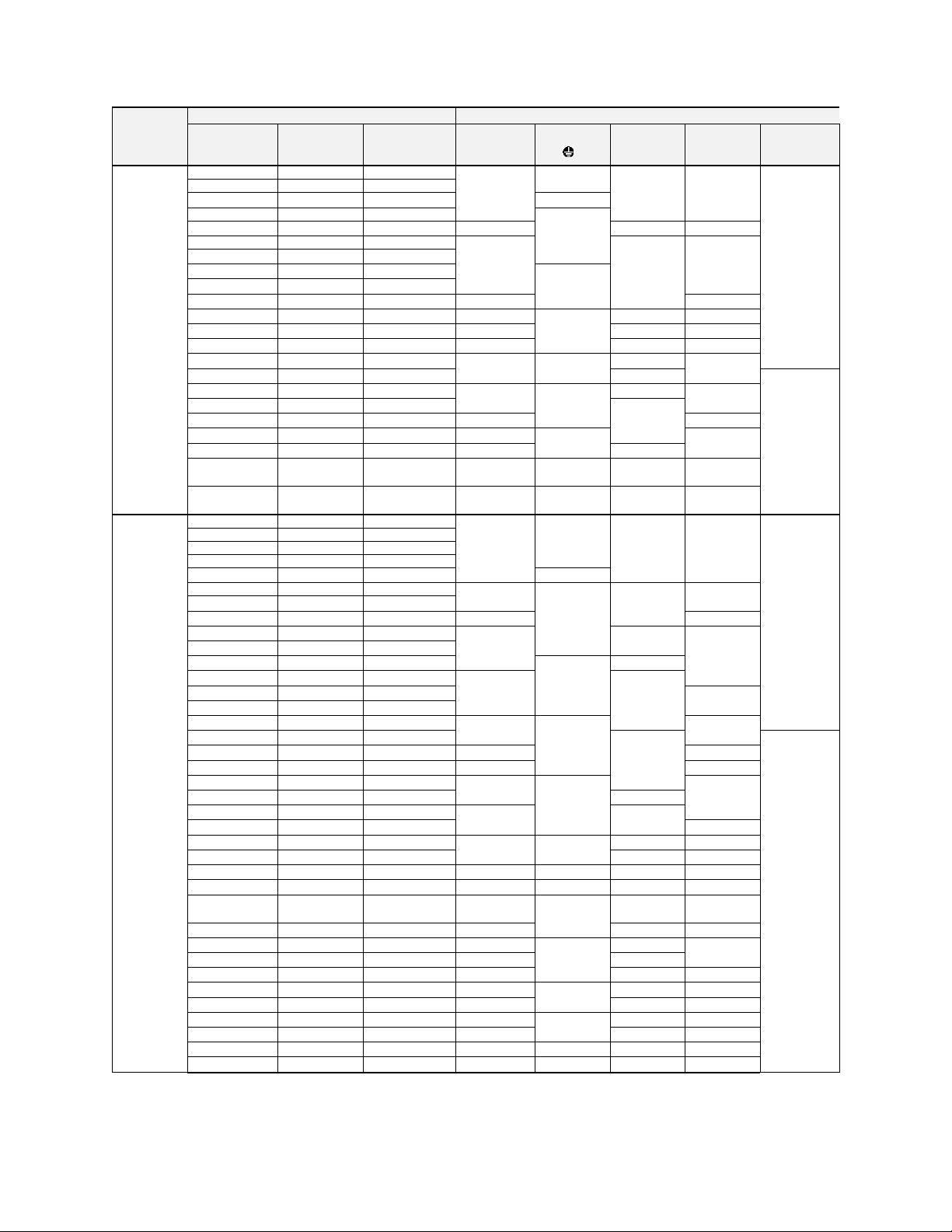
Power supply
voltage
Inverter type
Recommended wire size AWG (mm2)
Variable
Torque mode
Constant
Torque mode
CT-Vector
mode
L1/R, L2/S,
L3/T
Grounding
[ G]
U, V, W
DCR
[P1, P(+)]
Braking
resistor
[P(+), DB]
Single-phase/
Three-phase
230V
EQ7-20P5-C
EQ7-20P5-C
EQ7-20P5-C
14 (2.1)
14 (2.1)
14 (2.1)
14 (2.1)
10 (5.3)
EQ7-2001-C
EQ7-2001-C
EQ7-2001-C
EQ7-2002-C
EQ7-2002-C
EQ7-2002-C
12 (3.3)
EQ7-2003-C
EQ7-2003-C
EQ7-2003-C
10 (5.3)
EQ7-2005-C
EQ7-2005-C
EQ7-2005-C
10 (5.3)
12 (3.3)
10 (5.3)
EQ7-2007-C
EQ7-2007-C
EQ7-2007-C
8 (8.4)
8 (8.4)
8 (8.4)
--
EQ7-2010-C
EQ7-2010-C
EQ7-2010-C
--
8 (8.4)
--
--
EQ7-2015-C
EQ7-2015-C
EQ7-2015-C
EQ7-2020-C
6 (13.3)
4 (21.2)
EQ7-2020-C
EQ7-2020-C
EQ7-2025-C
4 (21.2)
6 (13.3)
6 (13.3)
3 (26.7)
EQ7-2025-C
EQ7-2025-C
EQ7-2030-C
3 (26.7)
4 (21.2)
2 (33.6)
EQ7-2030-C
EQ7-2030-C
EQ7-2040-C
2 (33.6)
3 (26.7)
1 (42.4)
EQ7-2040-C
EQ7-2040-C
--
2/0 (67.4)
4 (21.2)
2 (33.6)
2/0 (67.4)
--
EQ7-2050-C
1 (42.4)
--
EQ7-2050-C
EQ7-2050-C
--
3/0 (85)
3 (26.7)
1/0 (53.5)
4/0 (107.2)
--
--
EQ7-2060-C
4/0 (107.2)
EQ7-2060-C
EQ7-2060-C
EQ7-2075-C
4/0 (107.2)
250 (127)
EQ7-2075-C
EQ7-2075-C
EQ7-2100-C
2/0 (67.4) 2
2 (33.6)
350 (177)
EQ7-2100-C
EQ7-2100-C
EQ7-2125-C
3/0 (85) 2
3/0 (85) 2
EQ7-2125-C
EQ7-2125-C
EQ7-2150-C
4/0 (107.2) 2
1 (42.4)
4/0 (107.2)
2
500 (253)
EQ7-2150-C
EQ7-2150-C
--
300 (152) 2
1/0 (53.5)
300 (152) 2
4/0 (107.2)
2
Single-phase/
Three-phase
460V
EQ7-40P5-C
EQ7-40P5-C
EQ7-40P5-C
14 (2.1)
14 (2.1)
14 (2.1)
14 (2.1)
10 (5.3)
EQ7-4001-C
EQ7-4001-C
EQ7-4001-C
EQ7-4002-C
EQ7-4002-C
EQ7-4002-C
EQ7-4003-C
EQ7-4003-C
EQ7-4003-C
EQ7-4005-C
EQ7-4005-C
EQ7-4005-C
12 (3.3)
EQ7-4007-C
EQ7-4007-C
EQ7-4007-C
12 (3.3)
10 (5.3)
12 (3.3)
12 (3.3)
--
--
EQ7-4010-C
EQ7-4010-C
EQ7-4010-C
EQ7-4015-C
10 (5.3)
10 (5.3)
EQ7-4015-C
EQ7-4015-C
--
8 (8.4)
10 (5.3)
8 (8.4)
--
--
EQ7-4020-C
EQ7-4020-C
EQ7-4020-C
--
8 (8.4)
8 (8.4)
--
--
EQ7-4025-C
6 (13.3)
6 (13.3)
EQ7-4025-C
EQ7-4025-C
EQ7-4030-C
6 (13.3)
EQ7-4030-C
EQ7-4030-C
EQ7-4040-C
EQ7-4040-C
EQ7-4040-C
--
4 (21.2)
6 (13.3)
4 (21.2)
--
--
EQ7-4050-C
2 (33.6)
--
EQ7-4050-C
EQ7-4050-C
EQ7-4060-C
3 (26.7)
2 (33.6)
EQ7-4060-C
EQ7-4060-C
EQ7-4075-C
2 (33.6)
1 (42.4)
EQ7-4075-C
EQ7-4075-C
EQ7-4100-C
1/0 (53.5)
4 (21.2)
1/0 (53.5)
EQ7-4100-C
EQ7-4100-C
--
1/0 (53.5)
--
--
EQ7-4125-C
2/0 (67.4)
4/0 (107.2)
EQ7-4125-C
EQ7-4125-C
EQ7-4150-C
3/0 (85)
EQ7-4150-C
EQ7-4150-C
EQ7-4200-C
1/0 (53.5)
3 (26.7)
1/0 (53.5)
4/0 (107.2)
EQ7-4200-C
EQ7-4200-C
EQ7-4250-C
2 (33.6)
250 (127)
EQ7-4250-C
EQ7-4250-C
EQ7-4300-C
3/0 (85) 2
2 (33.6)
3/0 (85) 2
350 (177)
EQ7-4300-C
EQ7-4300-C
EQ7-4350-C
4/0 (107.2) 2
1 (42.4)
250 (127) 2
600 (304)
EQ7-4350-C
EQ7-4350-C
EQ7-4450-C
250 (127) 2
1/0 (53.5)
300 (152) 2
4/0 (107.2)
2
--
EQ7-4450-C
--
300 (152) 2
350 (177) 2
250 (127) 2
EQ7-4450-C
--
--
400 (203) 2
2/0 (67.4)
400 (203) 2
300 (152) 2
--
--
EQ7-4500-C
250 (127) 2
300 (152) 2
--
EQ7-4500-C
EQ7-4600-C
300 (152) 2
350 (177) 2
350 (177) 2
EQ7-4500-C
EQ7-4600-C
EQ7-4700-C
400 (203) 2
3/0 (85)
400 (203) 2
400 (203) 2
EQ7-4600-C
EQ7-4700-C
EQ7-4800-C
500 (253) 2
500 (253) 2
500 (253) 2
EQ7-4700-C
EQ7-4800-C
--
600 (304) 2
4/0 (107.2)
600 (304) 2
300 (152) 3
EQ7-4800-C
--
EQ7-4900-C
350 (177) 3
400 (203) 3
400 (203) 3
EQ7-4900-C
--
EQ7-41000-C
500 (253) 3
250 (127)
600 (304) 3
600 (304) 3
EQ7-41000-C
--
--
600 (304) 3
350 (177)
500 (253) 4
400 (203) 4
Table 2.6 Recommended Wire Sizes
Note: The wire sizes above are specified for 75 C (167 F) copper (Cu) wire.
2-7
Page 31

Terminals common to all inverters
Recommended wire size
AWG (mm2)
Remarks
Auxiliary control power input terminals [R0] and [T0]
14 (2.1)
2 HP or above
Auxiliary fan power input terminals [R1] and [T1]
230 V series with 60 HP or above
460 V series with 125 HP or above
Terminal type
Screw size: M3 (0.7 N·m)
Spring (screwless)
Recommended wiring size
(mm2)*
0.75
0.65 to 0.82 (AWG 19 or
18)
e.g. EQ7-4005-C
e.g. EQ7-2020-C
(2) Arrangement of control circuit terminals (common to all inverter types)
* Using wires exceeding the recommended sizes may lift the front cover
depending upon the number of wires used, impeding keypad's normal
operation.
2.3.3 Wiring precautions
Follow the rules below when performing wiring for the inverter.
(1) Make sure that the source voltage is within the rated voltage range specified on the nameplate.
(2) Be sure to connect the three-phase power wires to the main circuit power input terminals L1/R, L2/S and L3/T of
the inverter. If the power wires are connected to other terminals, the inverter will be damaged when the power is
turned ON.
(3) Always connect the grounding terminal to prevent electric shock, fire or other disasters and to reduce electric
noise.
(4) Use crimp terminals covered with insulated sleeves for the main circuit terminal wiring to ensure a reliable
connection.
(5) Keep the power supply wiring (primary circuit) and motor wiring (secondary circuit) of the main circuit, and control
circuit wiring as far away as possible from each other.
(6) After removing a screw from the main circuit terminal block, be sure to restore the screw even if no wire is
connected.
(7) Use the wiring guide to separate wiring. For inverters of 5 HP or below, the wiring guide separates the main circuit
wires and the control circuit wires. For those of 7.5 to 40 HP, it separates the upper and lower main circuit wires,
and control circuit wires. Be careful about the wiring order.
Preparing for the wiring guide
Inverters of 20 to 40 HP (three-phase, 230 V series) are sometimes lacking in wiring space for main circuit wires
depending upon the wire materials used. To assure a sufficient wiring space, remove the clip-off sections (see
below) as required with a nipper. Note that the enclosure rating of IP20 may not be ensured when the wiring guide
itself is removed to secure a space for thick main circuit wiring.
2-8
Page 32

Before removal of clip-off sections After removal of clip-off sections
Wiring Guide (e.g. EQ7-4025-C)
(8) In some types of inverters, the wires from the main circuit terminal block cannot be routed straight into the terminal.
Route such wires as shown below so that the front cover can be reinstalled.
(9) For inverters of 900 and 1000 HP, two L2/S input terminals are arranged vertically to the terminal block. When
connecting wires to these terminals, use the bolts, washers and nuts that come with the inverter, as shown below.
2-9
Page 33

• When wiring the inverter to the power source, insert a recommended molded case circuit breaker (MCCB) or
residual-current-operated protective device (RCD)/earth leakage circuit breaker (ELCB) (with overcurrent
protection) in the path of each pair of power lines to inverters. Use the recommended devices within the
recommended current capacity.
• Be sure to use wires in the specified size.
• Tighten terminals with specified torque.
Otherwise, a fire could occur.
• When there is more than one combination of an inverter and motor, do not use a multiconductor cable for the
purpose of running the leads together.
• Do not connect a surge killer to the inverter's output (secondary) circuit.
Doing so could cause a fire.
• Ground the inverter in compliance with the national or local electric code.
• Be sure to ground the inverter's grounding terminals G.
Otherwise, an electric shock or fire could occur.
• Qualified electricians should carry out wiring.
• Be sure to perform wiring after turning the power OFF.
Otherwise, electric shock could occur.
• Be sure to perform wiring after installing the inverter unit.
Otherwise, electric shock or injuries could occur.
• Ensure that the number of input phases and the rated voltage of the product match the number of phases and
the voltage of the AC power supply to which the product is to be connected.
Otherwise, a fire or an accident could occur.
• Do not connect the power source wires to inverter output terminals (U, V, and W).
Doing so could cause fire or an accident.
2-10
Page 34

2.3.4 Wiring of main circuit terminals and grounding terminals
This section shows connection diagrams with the Enable input function used.
SINK mode input by factory default
2-11
Page 35

When there is more than one combination of an inverter and motor, do not use a multi-conductor cable for the
purpose of running the leads together.
*1 Install a recommended molded case circuit breaker (MCCB) or residual-current-operated protective device
(RCD)/earth leakage circuit breaker (ELCB) (with overcurrent protection function) in the primary circuit of the
inverter to protect wiring. Ensure that the circuit breaker capacity is equivalent to or lower than the recommended
capacity.
*2 Install a magnetic contactor (MC) for each inverter to separate the inverter from the power supply, apart from the
MCCB or RCD/ELCB, when necessary.
Connect a surge absorber in parallel when installing a coil such as the MC or solenoid near the inverter.
*3 The R0 and T0 terminals are provided for inverters with a capacity of 2 HP or above.
To retain an alarm output signal ALM issued on inverter's programmable output terminals by the protective function
or to keep the keypad alive even if the main power has shut down, connect these terminals to the power supply
lines. Without power supply to these terminals, the inverter can run.
*4 Normally no need to be connected. Use these terminals when the inverter is equipped with a high power-factor,
regenerative PWM converter (RHC series).
*5 When connecting an optional DC reactor (DCR), remove the jumper bar from the terminals P1 and P(+).
EQ7-2100-C/EQ7-4100-C and larger HP models require a DCR (packed with the EQ7) to be connected.
Use a DCR when the capacity of the power supply transformer exceeds 500 kVA and is 10 times or more the
inverter rated capacity, or when there are thyristor-driven loads in the same power supply line.
*6 EQ7-2015-C/EQ7-4015-C and smaller have a built-in braking resistor (DBR) between the terminals P(+) and DB.
When connecting an external braking resistor (DBR), be sure to disconnect the built-in one.
*7 A grounding terminal for a motor. Use this terminal if needed.
*8 For control signal wires, use twisted or shielded-twisted wires. When using shielded-twisted wires, connect the
shield of them to the common terminals of the control circuit. To prevent malfunction due to noise, keep the control
circuit wiring away from the main circuit wiring as far as possible (recommended: 10 cm/3.9 inches or more). Never
install them in the same wire duct. When crossing the control circuit wiring with the main circuit wiring, set them at
right angles.
*9 The connection diagram shows factory default functions assigned to digital input terminals [X1] to [X7], [FWD] and
[REV], transistor output terminals [Y1] to [Y4], and relay contact output terminals [Y5A/C] and [30A/B/C].
*10 Switching connectors in the main circuits. For details, refer to "Instruction manual section 2.3.4 Switching
connectors" later in this section.
*11 Slide switches on the control printed circuit board (control PCB). Use these switches to customize the inverter
operations. For details, refer to Section 2.3.6 "Setting up the slide switches."
*12 When the Enable input function is not to be used, keep terminals [EN1]-[PLC] and terminals [EN2]-[PLC]
short-circuited using jumper wires. For opening and closing the hardware circuit between terminals [EN1] and [PLC]
and between [EN2] and [PLC], use safety components such as safety relays and safety switches that comply with
EN954-1 or EN ISO13849-1 Category 3 or higher.
*13 To bring the inverter into compliance with the European Standard, Low Voltage Directive EN61800-5-1, be sure to
insert the specified fuse in the primary circuit of the inverter.
Primary grounding terminal ( G) for inverter enclosure
Two grounding terminals ( G) are not exclusive to the power supply wiring (primary circuit) or motor wiring (secondary
circuit). Be sure to ground either of the two grounding terminals for safety and noise reduction. The inverter is designed
for use with safety grounding to avoid electric shock, fire and other disasters.
The grounding terminal for inverter enclosure should be grounded as follows:
1) Ground the inverter in compliance with the national or local electric code.
2) Use a thick grounding wire with a large surface area and keep the wiring length as short as possible.
Inverter output terminals U, V, and W and secondary grounding terminals ( G) for motor
Inverter’s output terminals should be connected as follows:
1) Connect the three wires of the 3-phase motor to terminals U, V, and W, aligning the phases each other.
2) Connect the secondary grounding wire to the grounding terminal ( G).
2-12
Page 36

• The wiring length should be 33 ft (10 m) or below.
• Do not remove the jumper bar when a DCR is not used.
• The EQ7-2100-C / EQ7-4100-C and higher types come with a DCR. Be sure to connect the DCR.
• If a PWM converter is connected to the inverter, no DCR is required.
Be sure to connect an optional DC reactor (DCR) when the capacity of the power supply transformer exceeds 500
kVA and is 10 times or more the inverter rated capacity.
Otherwise, a fire could occur.
Capacity
(HP)
Braking transistor
Built-in DC braking
resistor (DBR)
Optional devices
Option mounting
steps required
0.5 to 15
Built-in
Built-in
External DC braking resistor
(with a larger capacity)
1), 2), 3)
20 to 40
Built-in
None
External DC braking resistor
2), 3)
When connecting a DC braking resistor (DBR), never connect it to terminals other than terminals P(+) and DB.
Otherwise, a fire could occur.
DC reactor terminals P1 and P (+)
Connect a DC reactor (DCR) to these terminals for power factor correction.
1) Remove the jumper bar from terminals P1 and P(+).
2) Connect an optional DCR to those terminals.
DC braking resistor terminals P(+) and DB (for inverters of 40 HP or below)
For inverters of 15 HP or below, if the capacity of the built-in DC braking resistor (DBR) is insufficient since the inverter
undergoes frequent start/stop or heavy inertial load, mount an optional external DC braking resistor (DBR) with a larger
capacity to increase the braking capability, using the following steps. Before mounting the external DBR, remove the
built-in DBR.
1) For inverters of 0.5 to 5 HP, disconnect the wiring of the built-in DBR from terminals P(+) and DB; for those of 7.5 to
15 HP, disconnect the wiring from terminal DB and the internal relay terminal (see the figure below).
Insulate the terminals of the disconnected wires with insulating tape or other materials.
2) Connect an optional DBR to terminals P(+) and DB.
The internal relay terminal on inverters of 7.5 to 15 HP is left unused.
3) Arrange the DBR and inverter so that the wiring length comes to 16 ft (5 m) or less and twist the two DBR wires or
route them together in parallel.
2-13
Page 37

Capacity
(HP)
Braking
transistor
Built-in DC braking
resistor (DBR)
Optional devices
Devices and terminals
50 to 1000
None
None
Braking unit
Inverter - Braking unit:
P(+) and N(-)
DC braking resistor
(DBR)
Braking unit -DBR:
P(+) and DB
When you need to use the DC link bus terminals P(+) and N(-), consult your TECO-Westinghouse Motor
Company representative.
Connector
configuration
Power source voltage
398 to 440 V/50 Hz, 430 to 480 V/60 Hz
(Factory default)
380 to 398 V/50 Hz
380 to 430 V/60 Hz
Connector configuration
Power source voltage
398 to 440 V/50 Hz, 430 to 480 V/60 Hz
(Factory default)
380 to 398 V/50 Hz,
380 to 430 V/60 Hz
The allowable power input voltage fluctuation is within -15% to +10% of the power source voltage.
CN UX (red)
CN UX (red)
CN UX (red)
CN UX (red)
DC link bus terminals P(+) and N(-)
1) Connecting an optional braking unit or DC braking resistor (DBR)
Inverters of 50 HP or above require both a braking unit and DBR.
Connect the terminals P(+) and N(-) of a braking unit to those on the inverter. Arrange the inverter and the braking
unit so that the wiring length comes to 16 ft (5 m) or less and twist the two wires or route them together in parallel.
Next, connect the terminals P(+) and DB of a DBR to those on the braking unit. Arrange the braking unit and DBR
so that the wiring length comes to 33 ft (10 m) or less and twist the two wires or route them together in parallel.
For details about the wiring, refer to the Braking Unit Instruction Manual.
2) Connecting other external devices
A DC link bus of other inverter(s) or a PWM converter is connectable to these terminals.
Switching connectors
Power switching connectors (CN UX) (on inverters of 125 HP or above for 460 V)
Inverters of 125 HP or above for 460 V are equipped with a set of switching connectors (male) which should be
configured according to the power source voltage and frequency. By factory default, a jumper (female connector) is set
to U1. If the power supply to the main power inputs (L1/R, L2/S, L3/T) or the auxiliary fan power input terminals (R1,
T1) matches the conditions listed below, change the jumper to U2.
For the switching instructions, see Figures 2.6 and 2.7.
(a) EQ7-4125-C to EQ7-4200-C
(b) EQ7-4250-C to EQ7-41000-C
2-14
Page 38

Connector configuration
Use conditions
When not using terminal R1 or T1
(Factory default)
When using terminals R1 and T1
• Feeding the DC-linked power
• Combined with a PWM converter
Connector
configuration
Use conditions
When not using terminal R1 or T1
(Factory default)
When using terminals R1 and T1
• Feeding the DC-linked power
• Combined with a PWM converter
By factory default, the fan power supply switching connectors CN R and CN W are set on the FAN and NC
positions, respectively. Do not exchange them unless you drive the inverter with a DC-linked power supply.
Wrong configuration of these switching connectors cannot drive the cooling fans, causing a heat sink overheat
alarm 0h1 or a charger circuit alarm pbf.
(a) EQ7-2060-C to EQ7-2125-C,
EQ7-4125-C to EQ7-4200-C
(b) EQ7-2150-C,
EQ7-4250-C to EQ7-41000-C
CN W (white)
CN R (red)
CN W (white)
CN R (red)
CN W
(white)
CN R
(red)
CN W
(white)
CN R
(red)
Power switching
connectors (CN UX)
Fan power
supply switching
connectors
(CN R and
CN W)
Auxiliary fan
power input
terminals
Power PCB
Auxiliary power input
terminals
Power switching
connectors (CN UX)
Fan power
supply
switching
connectors
(CN R and
CN W)
Auxiliary fan power input
terminals
Auxiliary
power input
terminals
Keypad enclosure
Fan power supply switching connectors (CN R and CN W) (on inverters of 60 HP or above for 230 V and
those of 125 HP or above for 460 V)
The standard EQ7 series accepts DC-linked power input in combination with a PWM converter. Inverters of 60 HP or
above for 230 V and those of 125 HP or above for 460 V, however, contain AC-driven components such as AC fans. To
supply AC power to those components, exchange the CN R and CN W connectors as shown below and connect the
AC power line to the auxiliary fan power input terminals (R1, T1).
For the switching instructions, see Figures 2.6 and 2.7.
(a) EQ7-2060-C to EQ7-2125-C, EQ7-4125-C to EQ7-4200-C
b) EQ7-2150-C, EQ7-4150-C to EQ7-41000-C
Location of the switching connectors
The switching connectors are located on the power printed circuit board (power PCB) as shown below.
Figure 2.6 Location of Switching Connectors and Auxiliary Power Input Terminals
2-15
Page 39

Figure 2.7 Inserting/Removing the Jumpers
To remove each of the jumpers, pinch its upper side
between your fingers, unlock its fastener, and pull it up.
When mounting it, fit the jumper over the connector until it
snaps into place.
It is recommended to insert a manually operable magnetic contactor (MC) that allows you to disconnect the
inverter from the power supply in an emergency (e.g., when the protective function is activated), preventing a
failure or accident from causing secondary disasters.
When introducing a residual-current-operated protective device (RCD)/earth leakage circuit breaker (ELCB),
connect its output (secondary) side to terminals R0 and T0. Connecting its input (primary) side to those
terminals causes the RCD/ELCB to malfunction since the input power voltage to the inverter is three-phase but
the one to terminals R0 and T0 is single-phase. To avoid such problems, be sure to insert an isolation
transformer or auxiliary B contacts of a magnetic contactor in the location shown in Figure 2.8.
Figure 2.8 Connection Example of Residual-current-operated Protective Device (RCD)/
Earth Leakage Circuit Breaker (ELCB)
Main circuit power input terminals L1/R, L2/S, and L3/T (three-phase input)
The three-phase input power lines are connected to these terminals.
1) For safety, make sure that the molded case circuit breaker (MCCB) or magnetic contactor (MC) is turned OFF
before wiring the main circuit power input terminals.
2) Connect the main circuit power supply wires (L1/R, L2/S and L3/T) to the input terminals of the inverter via an
MCCB or residual-current-operated protective device (RCD)/earth leakage circuit breaker (ELCB)*, and an MC if
necessary.
It is not necessary to align phases of the power supply wires and the input terminals of the inverter with each other.
* With overcurrent protection
Auxiliary control power input terminals R0 and T0 (on inverters of 2 HP or above)
In general, the inverter runs normally without power supplied to the auxiliary control power input terminals R0 and T0. If
the inverter main power is shut down, however, no power is supplied to the control circuit so that the inverter cannot
issue a variety of output signals or display on the keypad.
To retain an alarm output signal ALM issued on inverter's programmable output terminals by the protective function or
to keep the keypad alive even if the main power has shut down, connect the auxiliary control power input terminals R0
and T0 to the power supply lines. If a magnetic contactor (MC) is installed in the inverter's primary circuit, connect the
primary circuit of the MC to these terminals R0 and T0.
Terminal rating:
200 to 240 VAC, 50/60 Hz, Maximum current 1.0 A (230 V series with 40 HP or below)
200 to 230 VAC, 50/60 Hz, Maximum current 1.0 A (230 V series with 50 HP or above)
380 to 480 VAC, 50/60 Hz, Maximum current 0.5 A (460 V series)
2-16
Page 40

When connecting a PWM converter with an inverter, do not connect the power supply line directly to terminals
R0 and T0. If a PWM is to be connected, insert an isolation transformer or auxiliary B contacts of a magnetic
contactor at the power supply side.
For connection examples at the PWM converter side, refer to the PWM Converter Instruction Manual.
Figure 2.9 Connection Example of PWM Converter
Auxiliary fan power input terminals R1 and T1
Inverters of 60 HP or above for 230 V and those of 125 HP or above for 460 V are equipped with terminals R1 and T1.
Only if the inverter works with the DC-linked power input whose source is a PWM converter, these terminals are used
to feed AC power to the fans, while they are not used in any power system of ordinary configuration.
In this case, set up the fan power supply switching connectors (CN R and CN W).
Terminal rating:
200 to 220 VAC/50 Hz, 200 to 230 VAC/60 Hz, Maximum current 1.0 A (230 V series with 60 HP or above)
380 to 440 VAC/50 Hz, 380 to 480 VAC/60 Hz, Maximum current 1.0 A (460 V series with 125 to 800 HP)
380 to 440 VAC/50 Hz, 380 to 480 VAC/60 Hz, Maximum current 2.0 A (460 V series with 900 and 1000 HP)
2-17
Page 41

In general, the covers of the control signal wires are not specifically designed to withstand a high voltage (i.e.,
reinforced insulation is not applied). Therefore, if a control signal wire comes into direct contact with a live
conductor of the main circuit, the insulation of the cover might break down, which would expose the signal wire
to a high voltage of the main circuit. Make sure that the control signal wires will not come into contact with live
conductors of the main circuit.
Failure to observe these precautions could cause electric shock or an accident.
Noise may be emitted from the inverter, motor and wires.
Take appropriate measures to prevent the nearby sensors and devices from malfunctioning due to such noise.
An accident could occur.
Strip length of wire end
8 to 10 mm
0.31 to 0.39 inch
Type of screwdriver (tip shape)
Flat (0.6 3.5 mm/0.024 0.14 inch)
For strand wires, the strip length specified above should apply after twisting of them.
If the strip length is out of the specified range, the wire may not be firmly clamped or may be
short-circuited with other wires.
Wires
Flat screwdriver
Wires
Wire inlet
Clamp release button
2.3.5 Wiring for control circuit terminals
This section shows connection diagrams with the Enable input function used.
Connecting/disconnecting wires to/from a control circuit terminal of spring (screwless) type
Strip the wire end by 8 to 10 mm/0.31 to 0.39 inch as shown below.
Twist the end of the stripped wires for easy insertion and insert it firmly into the wire inlet on the control circuit
terminal. If the insertion is difficult, hold down the clamp release button on the terminal with a flat screwdriver.
When disconnecting the wires from the terminal, hold down the clamp release button on the terminal with a flat
screwdriver and pull out the wires. Connecting wire to terminal disconnecting wire from terminal
2-18
Page 42

Classifi-
cation
Symbol
Name
Functions
Analog input
[13]
Power supply
for the
potentiometer
Power supply (+10 VDC) for an external frequency command potentiometer
(Variable resistor: 1 to 5k)
The potentiometer of 1/2 W rating or more should be connected.
[12]
Analog
setting
voltage input
(1) The frequency is commanded according to the external voltage input.
• 0 to 10 VDC/0 to 100% (Normal operation)
• +10 to 0 VDC/0 to 100% (Inverse operation)
(2) In addition to frequency setting, PID command, PID feedback signal, auxiliary frequency
command setting, ratio setting, torque limiter level setting, or analog input monitor can be
assigned to this terminal.
(3) Hardware specifications
• Input impedance: 22k
• The maximum input is 15 VDC, however, the voltage higher than 10 VDC is handled
as 10 VDC.
• Inputting a bipolar analog voltage (0 to 10 VDC) to terminal [12] requires setting function
code C35 to "0."
[C1]
Analog
setting
current input
(1) The frequency is commanded according to the external current input.
• 4 to 20 mA DC/0 to 100% (Normal operation)
• 20 to 4 mA DC/0 to 100 % (Inverse operation)
(2) In addition to frequency setting, PID command, PID feedback signal, auxiliary frequency
command setting, ratio setting, torque limiter level setting, or analog input monitor can be
assigned to this terminal.
(3) Hardware specifications
• Input impedance: 250
• The maximum input is +30 mA DC, however, the current larger than +20 mA DC is
handled as +20 mA DC.
PTC/NTC
thermistor
input
(1) Connects PTC (Positive Temperature
Coefficient)/NTC (Negative Temperature
Coefficient) thermistor for motor
protection. Ensure that the slide switch
SW5 on the control PCB is turned to the
PTC/NTC position (see section 2.3.6
"Setting up the slide switches").
The figure shown at the right illustrates the
internal circuit diagram where SW5
(switching the input of terminal [C1]
between C1 and PTC/NTC) is turned to
the PTC/NTC position. For details on
SW5, refer to Instruction manual section
2.3.6 "Setting up the slide switches." In
this case, you must change data of the
function code H26.
Figure 2.10 Internal Circuit Diagram
(SW5 Selecting PTC/NTC)
[V2]
Analog
setting
voltage input
(1) The frequency is commanded according to the external voltage input.
• 0 to 10 VDC/0 to 100 % (Normal operation)
• +10 to 0 VDC/0 to 100% (Inverse operation)
(2) In addition to frequency setting, PID command, PID feedback signal, auxiliary frequency
command setting, ratio setting, torque limiter level setting, or analog input monitor can be
assigned to this terminal.
(3) Hardware specifications
• Input impedance: 22k
• The maximum input is 15 VDC, however, the voltage higher than 10 VDC is handled
as 10 VDC.
• Inputting a bipolar analog voltage (0 to 10 VDC) to terminal [V2] requires setting
function code C45 to "0."
[11]
Analog
common
Common for analog input/output signals ([13], [12], [C1], [V2], [FM1] and [FM2]).
Isolated from terminals [CM] and [CMY].
Table 2.7 lists the symbols, names and functions of the control circuit terminals. The wiring to the control circuit
terminals differs depending upon the setting of the function codes, which reflects the use of the inverter. Route wires
properly to reduce the influence of noise.
Table 2.7 Symbols, Names and Functions of the Control Circuit Terminals
2-19
Page 43

Classifi-
cation
Symbol
Name
Functions
Digital input
- Since low level analog signals are handled, these signals are especially susceptible to the external noise
effects. Route the wiring as short as possible (within 66 ft (20 m)) and use shielded wires. In principle, ground
the shielded sheath of wires; if effects of external inductive noises are considerable, connection to terminal [11]
may be effective. As shown in Figure 2.11, be sure to ground the single end of the shield to enhance the shield
effect.
- Use a twin-contact relay for low level signals if the relay is used in the control circuit. Do not connect the relay's
contact to terminal [11].
- When the inverter is connected to an external device outputting the analog signal, the external device may
malfunction due to electric noise generated by the inverter. If this happens, according to the circumstances,
connect a ferrite core (a toroidal core or equivalent) to the device outputting the analog signal or connect a
capacitor having the good cut-off characteristics for high frequency between control signal wires as shown in
Figure 2.12.
- Do not apply a voltage of +7.5 VDC or higher to terminal [C1]. Doing so could damage the internal control
circuit.
Figure 2.11 Connection of Shielded Wire Figure 2.12 Example of Electric Noise Reduction
[X1]
Digital input 1
(1) Various signals such as "Coast to a stop," "Enable external alarm trip," and "Select
multi-frequency" can be assigned to terminals [X1] to [X7], [FWD] and [REV] by setting
function codes E01 to E07, E98, and E99. For details, refer to Chapter 4, Section 4.2
"Details of Function Codes."
(2) Input mode, i.e. SINK/SOURCE, is changeable by using the slide switch SW1. (Refer to
Instruction manual section 2.3.6 "Setting up the slide switches.")
(3) Switches the logic value (1/0) for ON/OFF of the terminals [X1] to [X7], [FWD], or [REV]. If
the logic value for ON of the terminal [X1] is 1 in the normal logic system, for example, OFF
is 1 in the negative logic system and vice versa.
(4) Digital input terminal [X7] can be defined as a pulse train input terminal with the function
codes.
Maximum wiring length 20 m/66 ft
Maximum input pulse 30 kHz: When connected to a pulse generator with open collector
transistor output
(Needs a pull-up or pull-down resistor. See notes on page
2-22.)
100 kHz: When connected to a pulse generator with complementary
transistor output
For the settings of the function codes, refer to Chapter 4 "FUNCTION CODES."
(Digital input circuit specifications)
Figure 2.13 Digital Input Circuit
[X2]
Digital input 2
[X3]
Digital input 3
[X4]
Digital input 4
[X5]
Digital input 5
[X6]
Digital input 6
[X7]
Digital input 7
[FWD]
Run forward
command
[REV]
Run reverse
command
Item
Min.
Max.
Operating
voltage
(SINK)
ON level
0 V
2 V
OFF level
22 V
27 V
Operating
voltage
(SOURCE)
ON level
22 V
27 V
OFF level
0 V
2 V
Operating current at ON
(Input voltage is at 0 V)
2.5 mA
5 mA
(For [X7])
(9.7 mA)
(16 mA)
Allowable leakage current at
OFF
0.5 mA
Table 2.7 Symbols, Names and Functions of the Control Circuit Terminals (Continued)
2-20
Page 44

Classifi-
cation
Symbol
Name
Functions
Digital input
[EN1]
[EN2]
Enable inputs
(1) Turning off the circuit between terminals [EN1] and [PLC] or terminals [EN2] and [PLC]
stops the inverter's output transistor. (Safe Torque Off: STO)
(2) These terminals are exclusively used for the source mode input and cannot be switched to
the sink mode.
(3) If either one of these input terminals is kept OFF for 50 ms or more, the inverter interprets it
as a discrepancy, causing an alarm ecf. This alarm state can be cleared only by turning the
inverter power off and on clears this alarm.
For details of connection to this terminal and precautions, refer to User Manual Chapter 9,
Section 9.4 "Compliance with EN954-1, Category 3."
<Terminal [EN1] [EN2] circuit specification>
[PLC]
Photocoupler
[CM]
<Control circuit>
5.4k
+24 VDC
[EN1]
5.4k
[EN2]
[PLC]
PLC signal
power
(1) Connects to the power supply of PLC output signals.
Rated voltage: +24 VDC (Allowable range: +22 to +27 VDC), Maximum 100 mA DC
(2) This terminal also supplies power to the load connected to the transistor output terminals.
Refer to "Transistor output" described later in this table for more.
[CM]
Digital input
common
Common terminal for digital input signals
This terminal is electrically isolated from the terminals [11]s and [CMY].
Using a relay contact to turn [X1] to [X7], [FWD], or [REV] ON or OFF
Figure 2.14 shows two examples of a circuit that uses a relay contact to turn control signal input [X1] to [X7],
[FWD], or [REV] ON or OFF. In circuit (a), the slide switch SW1 is turned to SINK, whereas in circuit (b) it is turned
to SOURCE.
Note: To configure this kind of circuit, use a highly reliable relay.
[PLC]
Photocoupler
[CM]
<Control circuit>
[X1] to [X7],
[FWD], [REV]
+24 VDC
SOURCE
SINK
[PLC]
Photocoupler
[CM]
<Control circuit>
[X1] to [X7],
[FWD], [REV]
+24 VDC
SOURCE
SINK
(a) With the switch turned to SINK
(b) With the switch turned to SOURCE
Figure 2.14 Circuit Configuration Using a Relay Contact
Using a programmable logic controller (PLC) to turn [X1] to [X7], [FWD], or [REV] ON or OFF
Figure 2.15 shows two examples of a circuit that uses a programmable logic controller (PLC) to turn control signal
input [X1] to [X7], [FWD], or [REV] ON or OFF. In circuit (a), the slide switch SW1 is turned to SINK, whereas in
circuit (b) it is turned to SOURCE.
In circuit (a) below, short-circuiting or opening the transistor's open collector circuit in the PLC using an external
power supply turns ON or OFF control signal [X1] to [X7], [FWD], or [REV]. When using this type of circuit, observe
the following:
- Connect the + node of the external power supply (which should be isolated from the PLC's power) to terminal
[PLC] of the inverter.
- Do not connect terminal [CM] of the inverter to the common terminal of the PLC.
Item
Min.
Max.
Operating
voltage
ON level
22 V
27 V
OFF level
0 V
2 V
Operating current at ON
(Input voltage is at 27 V)
2.5 mA
5 mA
Allowable leakage current at
OFF
05 mA
Table 2.7 Symbols, Names and Functions of the Control Circuit Terminals (Continued)
2-21
Page 45

Classifi-
cation
Symbol
Name
Functions
Digital input
[PLC]
Photocoupler
[CM]
<Control circuit>
[X1] t o [X7],
[FWD], [REV]
+24 VDC
Programmable
logic controller
SOURCE
SINK
[PLC]
Photocoupler
[CM]
<Control circuit>
[X1] to [X7],
[FWD], [REV]
+24 VDC
Programmable
logic controller
SOURCE
SINK
(a) With the switch turned to SINK (b) With the switch turned to SOURCE
Figure 2.15 Circuit Configuration Using a PLC
For details about the slide switch setting, refer to Instruction manual for section 2.3.6 "Setting up the slide switches."
For inputting a pulse train through the digital input terminal [X7]
• Inputting from a pulse generator with an open collector transistor output
Stray capacity on the wiring between the pulse generator and the inverter may disable transmission of the pulse
train. As a countermeasure against this problem, insert a pull-up resistor between the open collector output
signal (terminal [X7]) and the power source terminal (terminal [PLC]) if the switch selects the SINK mode input;
insert a pull-down resistor between the output signal and the digital common terminal (terminal [CM]) if the switch
selects the SOURCE mode input.
A recommended pull-up/down resistor is 1k 2 W. Check if the pulse train is correctly transmitted because stray
capacity is significantly affected by the wire types and wiring conditions.
Analog output
[FM1]
[FM2]
Analog
monitor
Both terminals output monitor signals for analog DC voltage (0 to +10 V) or analog DC current
(+4 to +20 mA). The output form (VO/IO) for each of [FM1] and [FM2] can be switched with the
slide switches on the control PCB and the function codes, as listed below.
Terminal
Terminal function is
specified by:
Output form
Content is
specified by:
Analog DC voltage
Analog DC current
[FM1]
Slide switch SW4
VO1
IO1
Function code
F31
Function code F29
0
1
[FM2]
Slide switch SW6
VO2
IO2
Function code
F35
Function code F32
0
1
The signal content can be selected from the following with function codes F31 and F35.
• Output frequency • Output current • Output voltage
• Output torque • Load factor • Input power
• PID feedback amount • Speed (PG feedback value) • DC link bus voltage
• Universal AO • Motor output • Cal bration
• PID command • PID output
* Input impedance of the external device: Min. 5k (at 0 to 10 VDC output)
(While the terminal is outputting 0 to 10 VDC, it is capable of driving up to two analog
voltmeters with 10 k impedance.)
* Input impedance of the external device: Max. 500 (at 4 to 20 mA DC output)
* Adjustable range of the gain: 0 to 300%
[11]
Analog
common
Two common terminals for analog input and output signals.
These terminals are electrically isolated from terminals [CM] and [CMY].
Table 2.7 Symbols, Names and Functions of the Control Circuit Terminals (Continued)
2-22
Page 46

Classifi-
cation
Symbol
Name
Functions
Transistor output
[Y1]
Transistor
output 1
(1) Various signals such as inverter running, speed/freq. arrival and overload early warning can
be assigned to any terminals, [Y1] to [Y4] by setting function code E20 to E24. Refer to
Chapter 4, Section 4.2 "Details of Function Codes" for details.
(2) Switches the logic value (1/0) for ON/OFF of the terminals between [Y1] to [Y4], and [CMY].
If the logic value for ON between [Y1] to [Y4] and [CMY] is 1 in the normal logic system, for
example, OFF is 1 in the negative logic system and vice versa.
[Y2]
Transistor
output 2
[Y3]
Transistor
output 3
(Transistor output circuit specification)
Photocoupler
<Control circuit>
[Y1]
to
[Y4]
[CMY]
31 to 35 V
Voltage
Current
Figure 2.16 Transistor Output Circuit
Item
Max.
Operation
voltage
ON level
2 V
OFF level
27 V
Maximum current at ON
50 mA
Leakage current at OFF
0.1 mA
Figure 2.17 shows examples of connection between the control circuit and a PLC.
[Y4]
Transistor
output 4
- When a transistor output drives a control relay, connect a surge-absorbing diode
across relay’s coil terminals.
- When any equipment or device connected to the transistor output needs to be
supplied with DC power, feed the power (+24 VDC: allowable range: +22 to +27 VDC,
100 mA max.) through the [PLC] terminal. Short-circuit between the terminals [CMY]
and [CM] in this case.
[CMY]
Transistor
output
common
Common terminal for transistor output signals
This terminal is electrically isolated from terminals [CM] and [11]s.
Connecting programmable logic controller (PLC) to terminal [Y1], [Y2], [Y3] or [Y4]
Figure 2.17 shows two examples of circuit connection between the transistor output of the inverter’s control
circuit and a PLC. In example (a), the input circuit of the PLC serves as a SINK for the control circuit output,
whereas in example (b), it serves as a SOURCE for the output.
C0
+24 VDC
Programmable
logic controller
SINK input
Photocoupler
<Control circuit>
[Y1]
to
[Y4]
[CMY]
31 to
35 V
Current
C0
Programmable
logic controller
SOURCE input
+24 VDC
Photocoupler
<Control circuit>
[Y1]
to
[Y4]
[CMY]
31 to
35 V
Current
(a) PLC serving as SINK
(b) PLC serving as SOURCE
Figure 2.17 Connecting PLC to Control Circuit
Relay output
[Y5A/C]
General
purpose relay
output
(1) A general-purpose relay contact output usable as well as the function of the transistor output
terminal [Y1], [Y2], [Y3] or [Y4].
Contact rating: 250 VAC 0.3 A, cos = 0.3, 48 VDC, 0.5 A
(2) Switching of the normal/negative logic output is applicable to the following two contact
output modes: "Active ON" (Terminals [Y5A] and [Y5C] are closed (excited) if the signal is
active.) and "Active OFF" (Terminals [Y5A] and [Y5C] are opened (non-excited) if the signal
is active while they are normally closed.).
Table 2.7 Symbols, Names and Functions of the Control Circuit Terminals (Continued)
2-23
Page 47

Classifi-
cation
Symbol
Name
Functions
Relay output
[30A/B/C]
Alarm relay
output
(for any error)
(1) Outputs a contact signal (SPDT) when a protective function has been activated to stop
the motor.
Contact rating: 250 VAC, 0.3A, cos = 0.3, 48 VDC, 0.5A
(2) Any one of output signals assigned to terminals [Y1] to [Y4] can also be assigned to this
relay contact to use it for signal output.
(3) Switching of the normal/negative logic output is applicable to the following two
contact output modes: "Active ON" (Terminals [30A] and [30C] are closed (excited) if the
signal is active.) and "Active OFF" (Terminals [30A] and [30C] are opened (non-excited) if
the signal is active while they are normally closed.).
Communication
[DX+]/
[DX-]/
[SD]
RS-485
communications
port 2
(Terminals on
control PCB)
A communications port transmits data through the RS-485 multipoint protocol between the
inverter and a computer or other equipment such as a PLC.
(For setting of the terminating resistor, refer to Section 2.3.6 "Setting up the slide switches.")
RJ-45
connector
for the
keypad
RS-485
communications
port 1
(Standard RJ-45
connector)
(1) Used to connect the inverter with the keypad. The inverter supplies the power to the
keypad through the pins specified below. The extension cable for remote operation also
uses wires connected to these pins for supplying the keypad power.
(2) Remove the keypad from the standard RJ-45 connector and connect the RS-485
communications cable to control the inverter through the PC or PLC (Programmable
Logic Controller). For setting of the terminating resistor, refer to Section 2.3.6 "Setting up
the slide switches."
Figure 2.18 RJ-45 Connector and its Pin Assignment*
* Pins 1, 2, 7, and 8 are exclusively assigned to power lines for the keypad, so do not
use those pins for any other equipment.
Table 2.7 Symbols, Names and Functions of the Control Circuit Terminals (Continued)
2-24
Page 48

- Route the wiring of the control circuit terminals as far from the wiring of the main circuit as possible.
Otherwise electric noise may cause malfunctions.
- Fix the control circuit wires with a cable tie inside the inverter to keep them away from the live parts of the
main circuit (such as the terminal block of the main circuit).
Before changing the switches or touching the control circuit terminal symbol plate, turn OFF the power and wait at
least five minutes for inverters of 40 HP or below, or at least ten minutes for those of 50 HP or above. Make
sure that the LED monitor and charging lamp are turned OFF. Further, make sure, using a multimeter or a similar
instrument, that the DC link bus voltage between the terminals P(+) and N(-) has dropped to the safe level (+25 VDC
or below).
An electric shock may result if this warning is not heeded as there may be some residual electric charge in
the DC bus capacitor even after the power has been turned OFF.
Control circuit terminal block
Cable tie
Wiring support
Wiring for control
circuit terminals
Left side panel
Wiring for control
circuit terminals
Section A
Details of Section A
Wiring for control circuit terminals
For EQ72125-C, EQ72150-C and EQ74250-C to EQ741000-C
(1) As shown in Figure 2.19, route the control circuit wires along the left side panel to the outside of the inverter.
(2) Secure those wires to the wiring support, using a cable tie (e.g., Insulok) with 0.15 inch (3.8 mm) or less in width
and 0.059 inch (1.5 mm) or less in thickness.
Figure 2.19 Wiring Route and Fixing Position for the Control Circuit Wires
2.3.6 Setting up the slide switches
Switching the slide switches located on the control PCB allows you to customize the operation mode of the analog
output terminals, digital I/O terminals, and communications ports. The locations of those switches are shown in Figure
2.20.
To access the slide switches, remove the front cover so that you can see the control PCB. For inverters of 50 HP or
above, open also the keypad enclosure.
For details on how to remove the front cover and how to open and close the keypad enclosure, refer to Section
2.3.1 "Removing and mounting the front cover and the wiring guide."
2-25
Page 49

Switch
Function
SW1
Switches the service mode of the digital input terminals between SINK and SOURCE.
▪ This switches the input mode of digital input terminals [X1] to [X7], [FWD] and [REV] to be
used as the SINK or SOURCE mode.
▪ The factory default is SINK.
SW2
Switches the terminating resistor of RS-485 communications port on the inverter ON and OFF.
(RS-485 communications port 2, on the control PCB)
▪ If the inverter is connected to the RS-485 communications network as a terminating device,
turn SW2 to ON.
SW3
Switches the terminating resistor of RS-485 communications port on the inverter ON and OFF.
(RS-485 communications port 1, for connecting the keypad)
▪ To connect a keypad to the inverter, turn SW3 to OFF. (Factory default)
▪ If the inverter is connected to the RS-485 communications network as a terminating device,
turn SW3 to ON.
SW4/SW6
Switches the output form of analog output terminals [FM1] and [FM2] between voltage and
current.
When changing the setting of SW4 and SW6, also change the data of function codes F29 and
F32, respectively.
Output form
[FM1]
[FM2]
SW4
F29 data
SW6
F32 data
Voltage output (Factory default)
VO1
0
VO2
0
Current output
IO1 1 IO2
1
SW5
Switches the property of the analog input terminal [C1] between analog setting current input,
PTC thermistor input, and NTC thermistor input.
When changing this switch setting, also change the data of function code H26.
Function
SW5
H26 data
Analog setting current input (Factory defau
C1
0
PTC thermistor input
PTC/NTC
1 (alarm) or 2
(warning)
NTC thermistor input
PTC/NTC
3
Switch Configuration and Factory Defaults
SW1
SW2
SW3
SW4/SW
6
SW5
Factory
default
SINK
OFF
OFF VO1/VO2 C1
---
SOURCE
ON
ON
IO1/IO2
PTC/NTC
Figure 2.20 Location of the Slide Switches
on the Control PCB
To move a switch slider, use a tool with a narrow tip (e.g., a tip of tweezers). Be careful not to touch other
electronic parts, etc. If the slider is in an ambiguous position, the circuit is unclear whether it is turned ON
or OFF and the digital input remains in an undefined state. Be sure to place the slider so that it contacts
either side of the switch.
Table 2.8 lists function of each slide switch.
Table 2.8 Function of Each Slide Switch
Figure 2.20 shows the location of slide switches on the control PCB for the input/output terminal configuration.
2-26
Page 50

Parts name
Type
Remarks
Extension cable
LAN cable
0BASE-T/100BASE-TX straight type cable
compliant with US ANSI/TIA/EIA-568A Category 5. (Less than 66 ft (20 m))
RJ-45
connector
M3 x 12
(Coarse thread tapping screws)
Panel
Inside the panel
Mount the keypad with four M3 x 12 screws provided--two fine thread
screws and two coarse thread tapping screws. The recommended
tightening torque is 6.2 lb-in (0.7 Nm).
For panel cutting dimensions, refer to Chapter 11, Section 11.3.2.
0.43 inches (11 mm)
(Effective length of
screw)
0 51 inches (13 mm)
(Effective length of
tapping screw)
M3 x 12
(Fine thread screws)
0.05 to 0 09 inch*
(1.2 to 2.3 mm)
* If the thickness of the panel wall is out of
the range specified above, use screws of
an appropriate length.
2.4 Mounting and Connecting the Keypad
The standard keypad TP-G1W-J1 meets UL Type 4 (NEMA4) by itself.
On the panel or at a remote site
The keypad can be mounted on the panel wall as shown below or installed at a remote site for operation on hand.
Figure 2.21 Mounting the Keypad on the Panel Wall
To mount the keypad on a place other than an inverter, the parts listed below are needed.
On the inverter
To remove the keypad from the inverter, pull it forward while holding down the hook (pointed by the arrow in Figure
2.22). When mounting it, put the keypad back into place in the reverse order of removal.
Figure 2.22 Removing the Keypad
2-27
Page 51

MOTOR
U V W
3Ø Induction
motor
Use L1, L2, L3 for
3Ø Input Power
Connect
frame to
ground
Input
Protection
(Fuse or Magnetic
Contactor)
To change direction of
motor rotation swap any
two of the three motor
leads.
L1
L2
L3
(R/L1)
(S/L2)
(T/L3)
(U/T1)
(V/T2)
(W/T3)
Ground
Use L1 & L3 for
1Ø Input Power
Ground
2
INPUT POWER
L1/R L2/S L3/T
P1
P(+)
N(-)
DB
WARNING DO NOT CONNECT ANY OF THE
FOLLOWING TERMINALS TO EARTH GROUND
Fig. 2.23
GND GND
*1 *1
*
DCR
P(+)
P1
EQ7
2.5 Input Power and Motor Connection
Checking prior to powering on
Fig.2.23 below shows the electrical connections for the input power and motor terminals for various EQ7 DRIVE
models. Verify the input power and motor terminals of the model you are installing. WITH POWER OFF, make the
appropriate connections.
Make sure to follow good wiring practices and all applicable codes. Ensure that the equipment is grounded
properly as shown.
DANGER, LETHAL VOLTAGES ARE PRESENT- Before applying power to the EQ7 drive, ensure that the
terminal cover is fastened and all wiring connections are secure. After the power has been turned OFF, wait at
least ten minutes until the charge indicator extinguishes completely before touching any wiring, circuit boards
or components.
2-28
*1. Refer to page 2-11 & 2-12 for connecting a DC reactor from the terminals P1 and P(+).
*2. Make sure the drive is properly sized for single phase input (consult factory).
(Refer to Table 2.6 Recommended Wire Sizes in this manual).
Page 52

Never connect power supply wires to the EQ7 drive output terminals U, V, and W. Doing so and turning
the power ON damages the inverter.
Be sure to connect the grounding wires of the EQ7 drive and the motor to the ground electrodes.
Otherwise, an electric shock could occur.
Check the following before powering on the EQ7 drive.
1) Check that the wiring is correct. Especially check the wiring to the EQ7 drive input terminals L1/R, L2/S
and L3/T and output terminals U, V, and W. Also check that the grounding wires are connected to the
grounding terminals ( G) correctly. See Figure 2.23.
2) Check the control circuit terminals and main circuit terminals for short circuits or ground faults.
3) Check for loose terminals, connectors and screws.
4) Check that the motor is separated from mechanical equipment.
5) Make sure that all switches of devices connected to the inverter are turned OFF. Powering on the
inverter with any of those switches being ON may cause an unexpected motor operation.
6) Check that safety measures are taken against runaway of the equipment. Also ensure that all safety
guards are in place to prevent human injury.
2-29
Page 53

Chapter 3 Operation using the Keypad
Item
Monitor
Functions
Monitors
Five-digit, 7-segment LED monitor which displays the following according to the operation modes:
In Run mode: Running status information (e.g., output frequency, current, and voltage).
In Programming mode: Same as above.
In Alarm mode: Alarm code, which identifies the alarm when the protective function is activated.
LCD monitor which displays the following according to the operation modes:
In Run mode: Running status information.
In Programming mode: Menus, function codes and their settings.
In Alarm mode: Alarm code, which identifies the alarm when the protective function is activated.
Indication
Units
In Run mode, these show the unit for the number displayed on the 7-segment LED monitor and the
running status information on the LCD monitor. For details, see the next page.
7-segment LED Monitor
Program
Indication units
STOP key
RUN key (forward)
RUN key (reverse)
Reset key
Shift key
LED light
DOWN key
UP key
Function/Data key
Remote/Local key
3.1 LED Monitor, LCD Monitor, and Keys
The keypad allows you to start and stop the motor, view various data including maintenance information and alarm
information, configure function codes, monitor I/O signal status, copy data, and calculate the load factor.
Table 3.1: Overview of Keypad Functions
3-1
Page 54

Table 3.1 Overview of Keypad Functions (Continued)
Item
Keys
Functions
Programming
keys
Switches the operation modes of the inverter.
Shifts the cursor to the right for entry of a numerical value.
Pressing this key after removing the cause of an alarm switches the inverter to Running
mode. This key is used to reset settings or screen transition.
and
UP and DOWN keys, which are used to select the setting items or change the function code
data.
Function/Data key, which switches the operation mode as follows:
In Run mode: Pressing this key switches the information to be displayed
concerning the status of the inverter (output frequency (Hz), output
current (A), output voltage (V), etc.).
In Programming mode: Pressing this key displays the function code and establishes the
newly entered data.
In Alarm mode: Pressing this key displays the details of the problem indicated by the
alarm code that has come up on the LED monitor.
Operation keys
Starts running the motor in the forward rotation.
Starts running the motor in the reverse rotation.
Stops the motor.
Holding down this key for more than 1 second toggles between local and remote modes.
LED
lamp
Lights while a run command is supplied to the inverter.
Type
Item
Description (information, condition, and status)
Unit of
number on
LED monitor
Hz
Output frequency and reference frequency
A
Output current
V
Output voltage
%
Calculated torque, load factor, and speed
r/min
Preset and actual motor speeds and preset and actual load shaft speeds
m/min
Preset and actual line speeds
kW
Input power and motor output
X10
Data exceeding 99,999
min
Preset and actual constant feeding rate times
sec
Timer
PID
PID process value
Details of Indicator Indexes
3-2
Page 55

Type
Item
Description (information, condition, and status)
Running status
FWD
Running in the forward rotation
REV
Running in the reverse rotation
STOP
No output frequency
Run command
source
REM
Remote mode
LOC
Local mode
COMM
Via communications link (RS-485 (standard, optional), fieldbus option)
JOG
Jogging mode
HAND
Via keypad (This item lights also in local mode.)
Mode
Description
Running Mode
This mode allows you to specify run/stop commands in regular operation. It is also possible to
monitor the running status in real time.
If a light alarm occurs, the * appears on the LED monitor.
Programming Mode
This mode allows you to configure function code data and check a variety of information relating
to the inverter status and maintenance.
Alarm Mode
If an alarm condition arises, the inverter automatically enters the Alarm mode in which you can
view the corresponding alarm code* and its related information on the LED and LCD monitors.
* Alarm code that represents the cause((s) of the alarm(s) that has been triggered by the protective
function. For details, refer to the "Protective Functions" in Chapter 10, Section 10.1.
Programming mode
Configura ion of function
code data and monitor of
maintenance/alarm info
and various status
Alarm mode
Display of alarm status
Occurrence of
an alarm
(Press this key if
an alarm has
occurred.)
Running mode
Release of
a light alarm
Monitor of running status
Light alarm displayed
Run/Stop of motor
Run/Stop of motor
Detection of
a light alarm
Power ON
Release of
an alarm
or
3.2 Overview of Operation Modes
The EQ7 features the following three operation modes.
Table 3.2 Operation Modes
Figures 3.1 shows the status transition of the inverter between these three operation modes.
Figure 3.1 Status Transition between Operation Modes
3-3
Page 56

3.3 Running Mode
Status/Direction
Display
Meaning
Running status
RUN
STOP
A run command is given or the inverter is running the motor.
A run command is not given and the inverter is stopped.
Rotational direction
FWD
REV
Blank
Running in the forward rotation
Running in the reverse rotation
Stopped
Rotational direc ion
Running status
Operation guide
3.3.1 Running or stopping the motor
By factory default, pressing the key starts running the motor in the forward direction and pressing the key
decelerates the motor to a stop. The key is disabled. Running or stopping the motor with the keypad is enabled only
in Running and Programming modes.
To run the motor in reverse direction or run the motor in reversible mode, change the setting of function code F02.
For details of function code F02, refer to Chapter 4 "FUNCTION CODES."
Figure 3.2 Rotational Direction of Motor
Note) The rotational direction of an IEC-compliant motor is opposite to the one shown above.
Displaying the running status on the LCD monitor
(1) When function code E45 (LCD monitor item selection) is set at "0"
The LCD monitor displays the running status, the rotational direction, and the operation guide.
(The upper indicators show the unit of values displayed on the LED monitor as detailed in Section 3.3.2. The lower
ones show the running status and run command source.)
Figure 3.3 Display of Running Status
The running status and the rotational direction are displayed as shown in Table 3.3.
Table 3.3 Running Status and Rotational Direction
3-4
Page 57

(2) When function code E45 (LCD monitor item selection) is set at "1"
Monitored Items on the
LED Monitor
Example
Unit
Meaning of Displayed Value
Function
code E43
Monitor page
#
Speed Monitor
Function code E48 specifies what to be displayed.
0
0
Output frequency 1
(before slip
compensation)
Hz
Frequency actually being output (Hz)
(E48 = 0)
Output frequency 2
(after slip
compensation)
Hz
Frequency actually being output (Hz)
(E48 = 1)
Reference frequency
Hz
Frequency actually being specified (Hz)
(E48 = 2)
Motor speed
r/mi
n
Output frequency (Hz) x
120
P01
(E48 = 3)
Load shaft speed
r/mi
n
Output frequency (Hz) x E50
(E48 = 4)
Line speed
m/mi
n
Output frequency (Hz) x E50
(E48 = 5)
Display speed (%)
%
Output frequency (Hz
)
Maximum frequency (Hz)
x 100
(E48 = 7)
Output current
A
Current output from the inverter in RMS
3
8
Input power
kW
Input power to the inverter
9
9
Calculated torque
%
Motor output torque in %
(Calculated value)
8
10
Output voltage
V
Voltage output from the inverter in RMS
4
11
Motor output
kW
Motor output in kW
16
12
Load factor
%
Load factor of the motor in % as the rated
output being at 100%
15
13
Output frequency
Output current
Bar chart
Calculated torque
The LCD monitor displays the output frequency, output current, and calculated torque in a bar chart.
(The upper indicators show the unit of values displayed on the LED monitor as detailed in Section 3.3.2. The lower
ones show the running status and run command source.)
The full scale (maximum value) for each parameter is as follows:
Output frequency: Maximum frequency
Output current: 200% of inverter’s rated current
Calculated torque: 200% of rated torque generated by motor
Figure 3.4 Bar Chart
3.3.2 Monitoring the running status on the LED monitor
The items listed below can be monitored on the 7-segment LED monitor. Immediately after the power is turned ON, the
monitor item specified by function code E43 is displayed.
Pressing the key in Running mode switches between monitor items in the sequence shown in Table 3.4. The "Monitor
page #" column shows the monitor page of the items supported.
Table 3.4 Items Monitored
3-5
Page 58

Table 3.4 Items Monitored (Continued)
Monitored Items on the
LED Monitor
Example
Unit
Meaning of Displayed Value
Function
code E43
Monitor
page #
PID command
(Note 1)
-
PID command/feedback amount
transformed to that of physical value of
the object to be controlled (e.g.,
temperature). Refer to function codes
E40 and E41 for details.
10
14
PID feedback amount
(Note 1)
-
12
15
PID output
(Note 1)
%
PID output in % as the maximum
frequency being at 100%
14
16
Analog input
(Note 2)
-
Analog input to the inverter in a format
suitable for a desired scale
Refer to function codes E40 and E41
for details.
17
18
Torque current
(Note 3)
%
Torque current command value or
calculated torque current
23
21
Magnetic flux command
(Note 3)
%
Magnetic flux command value
(Available only under vector control)
24
22
Input watt-hour
kWh
Input watt-hour (kWh
)
100
25
23
Monitor items
Operation guide
Monitor page #
(See Table 3.4.)
The LCD monitor (given below) shows information related to the item shown on the LED monitor. The monitor items on
the LED monitor can be switched by pressing the key.
(Note 1) These PID related items appear only under PID control specified by function code J01 (= 1, 2 or 3). When a PID
(Note 2) The analog input monitor appears only when the analog input monitor is enabled by any of function codes E61 to E63
(Note 3) Under V/f control, a zero (0) is displayed.
command or PID output is displayed, the dot at the lowest digit on the LED monitor blinks; when a PID feedback
amount is displayed, it is lit.
(Select terminal function).
Figure 3.5 LCD Monitor Sample Detailed for the LED Monitor Item
3-6
Page 59

3.3.3 Monitoring light alarms
Means that a light
alarm has occurred.
Rotational direction
Indicator indexes
Means that a light
alarm has occurred.
Operation guides
Running status
The has
disappeared and the
normal LED monitor is
displayed.
Rotational direction
Indicator indexes
Operation guides
Running status
The operation guides
remain displayed.
The EQ7 identifies abnormal states in two categories--Alarm and Light alarm. If the former occurs, the inverter
immediately trips; if the latter occurs, the appears on the LED monitor and the "L-ALARM" appears blinking in the
operation guide area on the LCD monitor, but the inverter continues to run without tripping.
Which abnormal states are categorized as a light alarm ("Light alarm" object) should be defined with function codes H81
and H82 beforehand.
Assigning the LALM signal to any one of the digital output terminals with any of function codes E20 to E24 and E27
(data = 98) enables the inverter to output the LALM signal on that terminal upon occurrence of a light alarm.
Figure 3.6 Display of Light Alarm
For details of the light alarms, refer to Chapter 10 "TROUBLESHOOTING."
How to check a light alarm
If a light alarm occurs, the appears on the LED monitor. To check the current light alarm, enter Programming mode
by pressing the key and select LALM1 on Menu #5 "Maintenance Information."
It is also possible to check the last three light alarms by selecting LALM2 (last) to LALM4 (3rd last).
For details of the menu transition of the maintenance information, refer to Section 3.4.6 "Reading maintenance
information."
How to remove the current light alarm
After checking the current light alarm, to switch the LED monitor from the indication back to the running status
display (e.g., output frequency), press the key in Running mode.
If the light alarm has been removed, the "L-ALARM" disappears and the LALM output signal turns OFF. If not (e.g. DC
fan lock), the on the LED monitor disappears so that normal monitoring becomes available, but the "L-ALARM"
remains displayed on the LCD monitor (as shown below) and the LALM output signal remains ON.
3-7
Page 60

3.4 Programming Mode
Menu #
Menu
Used to:
User
Manual
Section:
0
Quick Setup
Display only basic function codes previously selected.
3.4.1
1
Data Setting
Display and change the data of the function code selected.
(Note)
3.4.2
2
Data Checking
Display the function code selected and its data on the same
screen. Also this menu is used to change the function code
data or check whether the data has been changed from the
factory default.
3.4.3
3
Drive Monitoring
Display the running information required for maintenance or
test running.
3.4.4
4
I/O Checking
Display external interface information.
3.4.5
5
Maintenance Information
Display maintenance information including cumulative run
time.
3.4.6
6
Alarm Information
Display the recent four alarm codes. Also this menu is used
to view the information on the running status at the time the
alarm occurred.
3.4.7
7
Alarm Cause
Display the cause of the alarm.
3.4.8
8
Data Copying
Read or write function code data, as well as verifying it.
3.4.9
9
Load Factor
Measurement
Measure the maximum output current, average output
current, and average braking power.
3.4.10
10
User Setting
Add or delete function codes covered by Quick Setup.
3.4.11
11
Communication
Debugging
Confirm the data of function codes exclusively designed for
communication (S, M, W, X, and Z codes).
3.4.12
Programming mode provides you with these functions--setting and checking function code data, monitoring
maintenance information and checking input/output (I/O) signal status. These functions can be easily selected with a
menu-driven system. Table 3.5 lists menus available in Programming mode.
When the inverter enters Programming mode from the second time on, the menu se lected last in Programming mode
will be displayed.
Table 3.5 Menus Available in Programming Mode
Figure 3.7 shows the transitions between menus in Programming mode.
Figure 3.7 Menu Transition in Programming Mode
If no key is pressed for approx. 5 minutes, the inverter automatically goes back to Running mode and turns the backlight
OFF.
3-8
Page 61

3.4.1 Setting up function codes quickly using Quick Setup -- Menu #0 "Quick Setup" --
Function Code
Group
Function
Description
F codes
Fundamental functions
Functions concerning basic motor running
E codes
Extension terminal
functions
Functions concerning the assignment of control circuit terminals
Functions concerning the display of the LED monitor
C codes
Control functions
Functions associated with frequency settings
P codes
Motor 1 parameters
Functions for setting up characteristics parameters (such as
capacity) of the 1st motor
H codes
High performance functions
Highly added-value functions
Functions for sophisticated control
A codes
Motor 2 parameters
Functions for setting up characteristics parameters (such as
capacity) of the 2nd motor
J codes
Application functions 1
Functions for applications such as PID control
d codes
Application functions 2
Functions for applications such as speed control
y codes
Link functions
Functions for controlling communication
o codes
Option functions
Functions for options (Note)
Menu #0 "Quick Setup" in Programming mode quickly displays and sets up a basic set of function codes specified
beforehand.
Using Menu #10 "User Setting" adds or deletes function codes to/from the set of function codes registered for Quick
Setup by default. The set of function codes registered for Quick Setup is held in the inverter memory (not the keypad). If
the keypad on a particular inverter is mounted on any other inverter, therefore, the set of function codes held in the latter
inverter is subject to Quick Setup.
The set of function codes subject to Quick Setup can be copied with the copy function (Menu #8 "Data Copying").
Performing data initialization (function code H03) resets the set of function codes subject to Quick Setup to the factory
default.
For the list of function codes subject to Quick Setup by factory default, refer to Chapter 4 "FUNCTION CODES."
The menu transition in Menu #0 is just like that in Menu #1 "Data Setting" given in the next section.
Basic key operation
Same as the basic key operation for Menu #1 "Data Setting."
3.4.2 Setting up function codes -- Menu #1 "Data Setting" --
Menu #1 "Data Setting" in Programming mode allows you to set up all function codes for making the inverter functions
match your needs.
Table 3.6 Function Code List
(Note) The o codes are displayed only when the corresponding option is mounted on the inverter. For details, refer to the
instruction manual of the corresponding option.
Function codes requiring simultaneous keying
To modify the data of function code F00 (data protection), H03 (data initialization), or H97 (clear alarm data),
simultaneous keying of " + keys" or ”
+ keys" is required.
Changing, validating, and saving function code data when the inverter is running
Some function codes can be modified when the inverter is running. The modification may or may not take effect
immediately. For details, refer to the "Change when running" column in Chapter 5, Section 5.1 "Function Code Tables."
3-9
Page 62

Basic configuration of screens
Function code #, name
: Function code that has been changed from factory default
Data
Allowable entry range
Operation guide
Data before change
Data being changed
Menu screen
List of function codes
Function code data
modification screens
Function code
Func ion code name
Operation guide, scrolling horizontally to display the function of each key.
The function code currently selected blinks, indicating that the cursor has moved
to this position (F03 blinks in this example).
Figure 3.8 shows the LCD screen transition for Menu #1 "Data Setting."
A hierarchy exists among those screens that are shifted in the order of "menu screen," "list of function codes," and
"function code data modification screens."
On the modification screen of the target function code, you can modify or check its data.
Figure 3.8 Configuration of Screens for "DATA SET"
Screen samples for changing function code data
The "list of function codes" shows function codes, their names, and operation guides.
The "function code data modification screen" shows the function code, its name, its data (before and after change),
allowable entry range, and operation guides.
<Before change>
<Changing data>
Figure 3.9 Screen Samples for Changing Function Code Data
3-10
Page 63

Basic key operation
(1) To display this menu screen, press key in Running mode to switch to Programming mode.
Press key to establish the selected menu and proceed to a list of function codes.
((6) To go back to the menu screen, press key.)
(5) Press key to establish the function code data.
To cancel change of data, press key.
(2) Move the pointer to "1. DATA SET" with and keys.
(4) Change the function code data with and keys.
(3) Move the cursor with
and
keys to select the desired function code.
/
/
/
Press key to establish the selected function code and display its data screen.
This section gives a description of the basic key operation, following the example of the data changing flow shown
below. This example shows how to change F03 data (maximum frequency) from 58.0 Hz to 58.1 Hz.
(1) Turn the inverter ON. It automatically enters Running mode. In that mode, press the
Programming mode and display the menu screen.
key to switch to
(2) Move the pointer to "1. DATA SET" with the and keys, then press the key to proceed to a list of function
codes.
(3) Select the desired function code (F03 in this example) with the and keys, then press the key to display the
corresponding function code data screen.
(4) Change the function code data with the and keys.
Pressing the key causes the blinking digit place to shift (cursor shifting) (The blinking digit can be changed).
(5) Press the key to establish the function code data.
The data will be saved in the inverter's memory. The display returns to a list of function codes and the cursor moves
to the next function code (F04 in this example).
Pressing the key instead of the key cancels the new function code data, reverts to the previous data, returns to
a list of function codes, and returns the cursor to the previous function code (F03 in this example).
(6) Press the key to go back to the menu screen.
Figure 3.10 Screen Transition for "Data Checking"
3-11
Page 64

3.4.3 Checking changed function codes -- Menu #2 "Data Checking" --
Page # in
operation
guide
Item
Symbol
Description
1
Output frequency
Fot1
Output frequency (before slip compensation)
Output frequency
Fot2
Output frequency (after slip compensation)
Output current
Iout
Output current
Output voltage
Vout
Output voltage
2
Calculated torque
TRQ
Calculated output torque generated by motor
Reference frequency
Fref
Frequency specified by a frequency command
Running direction
FWD
REV
(Blank)
Forward
Reverse
Stopped
Current limit
IL
Current limiting
Undervoltage
Voltage limit
LU
VL
Undervoltage detected
Voltage limiting
Torque limit
TL
Torque limiting
Speed limit
SL
Speed limiting
Motor selected
M1-M4
Motor 1 to 4
Drive control
VF
DTV
VF-SC
VF-PG
VC-SL
VC-PG
V/f control without slip compensation
Dynamic torque vector control
V/f control with slip compensation
Dynamic torque vector control with speed sensor
Vector control without speed sensor
Vector control with speed sensor
3
Motor speed
SYN
P01
120
× Hz)frequency (Output
Load shaft speed
LOD
Output frequency (Hz) Function code E50
Line speed
LIN
Output frequency (Hz) Function code E50
Constant peripheral
speed control monitor
LSC
Actual peripheral speed under constant peripheral speed
control
Operation guide, scrolling horizontally to display the function of each key.
Function code
Function code data
Changed
Menu #2 "Data Checking" in Programming mode allows you to check function codes and their data that has been
changed. The function codes whose data has been changed from the factory defaults are marked with an asterisk ( ).
Select a function code and press the
key to view or change its data.
The LCD screen transition from Menu #2 is the same as that from Menu #1 "Data Setting," except a list of function codes
as shown below.
Figure 3.11 List of Function Codes
Basic key operation
Same as the basic key operation for Menu #1 "Data Setting."
3.4.4 Monitoring the running status -- Menu #3 "Drive Monitoring" --
Menu #3 "Drive Monitoring" in Programming mode allows you to monitor the running status during maintenance and test
running.
Table 3.7 Drive Monitoring Items
3-12
Page 65

Table 3.7 Drive Monitoring Items (Continued)
Page # in
operation
guide
Item
Symbol
Description
4
PID command value
SV
The PID command value and PID feedback amount are displayed
after conversion to the virtual physical values (e.g., temperature
or pressure) of the object to be controlled using function code E40
and E41 data (PID display coefficients A and B).
Display value = (PID command value or feedback amount)
(Coefficient A - B) + B
PID feedback amount
PV
PID output value
MV
PID output value, displayed in % (assuming the maximum
frequency (F03) as 100%).
5
Torque limit value A
TLA
Driving torque limit value A (based on motor rated torque)
Torque limit value B
TLB
Driving torque limit value B (based on motor rated torque)
Reference torque bias
TRQB
Reserved.
6
Current position pulse
P
Current position pulse for positioning control
Stop position target pulse
E
Stop position target pulse for positioning control
Position deviation pulse
dP
Position deviation pulse for positioning control
Positioning control status
MODE
Positioning control status
7
Motor temperature
NTC
Temperature detected by the NTC thermistor built in the motor
Ratio setting
Rati
When this setting is 100%, the LED monitor shows 1.00 time of
the value to be displayed.
Magnetic flux command
value
FLUX
Flux command value in %.
Deviation in SY synchronous
operation
SY-d
Deviation in SY synchronous operation
8
Current position pulse,
4-multiplied
P4
Current position pulse for positioning control
Stop position target pulse,
4-multiplied
E4
Stop position target pulse for positioning control
Position deviation pulse,
4-multiplied
dP4
Position deviation pulse for positioning control
Positioning control status
MODE
Reserved.
(1) To display this menu screen, press key in Running mode to switch to Programming mode.
(2) Move the pointer to "3. OPR MNTR" with and keys.
Select desired menu by moving the pointer with / key.
/
Basic key operation
(1) Turn the inverter ON. It automatically enters Running mode. In that mode, press the
Programming mode and display the menu screen.
(2) Move the pointer to "3. OPR MNTR" with the and keys.
(3) Press the key to establish the selected menu and proceed to a list of monitoring items (consisting of several
pages).
(4) Use the and keys to select the page on which the desired monitoring item is shown, then check the running
status information of that item.
(5) Press the key to go back to the menu screen.
Figure 3.12 shows an example of the LCD screen transition starting from Menu #3 "Drive Monitoring."
3-13
key to switch to
Page 66

Output frequency (before slip compensation)
Output frequency (after slip compensation)
Output current
Output voltage
Calculated torque
Reference frequency
Running status (See Table 3.7.)
Motor speed
Load shaft speed
Line speed
Constant peripheral speed control monitor
PID command value
PID feedback amount
PID output value
Torque limit value A
Torque limit value B
Reserved.
Current position pulse
Stop position target pulse
Position deviation pulse
Positioning control status
Motor temperature
Ratio setting
Magnetic flux command value
Deviation in SY synchronous operation
Current position pulse
Stop position target pulse
Position deviation pulse
Reserved.
: End of page
(3) Press key to establish the desired menu and proceed to a list of monitoring items.
1/8: Page # in operation guide, means that this page continues to the next page.
/
/
/ / /
/
(4) Use and keys to select the page on which the desired monitor item is shown.
((5) To go back to the menu screen, press key.)
/
Common operation items
To access the target data, switch to the desired page using the and keys.
: This page continues to the next page.
: This page is continued from the previous page and continues to the next page.
: This page is continued from the previous page.
Figure 3.12 Screen Transition for "Drive Monitoring"
3-14
Page 67

3.4.5 Checking I/O signal status -- Menu #4 "I/O Checking" --
Page # in
operation
guide
Item
Symbol
Description
1
Input signals on the
control circuit
terminals
FWD, REV,
X1 - X7, EN
ON/OFF state of input signals on the control circuit terminal
block.
(Highlighted when short-circuited; normal when open)
2
Input signals via
communications link
FWD, REV,
X1 - X7, XF,
XR, RST
Input information for function code S06 (communication)
(Highlighted when 1; normal when 0)
3
Output signals
Y1 - Y4, Y5,
30ABC
Output signal information
4
I/O signals
(hexadecimal)
Di
Input signals on the control circuit terminal block (in
hexadecimal)
Do
Output signals (in hexadecimal)
LNK
Input signal entered via communications link (in hexadecimal)
5
Analog input signals
12
Input voltage on terminal [12]
C1
Input current on terminal [C1]
V2
Input voltage on terminal [V2]
6
Analog output signals
FM1
FM1
FM2
FM2
Output voltage on terminal [FM1] *
Output current on terminal [FM1]
Output voltage on terminal [FM2]
Output current on terminal [FM2]
7
Input signals on the
digital input interface
card (option)
Di-o
Input signals on the option card in hexadecimal
Output signals on the
digital output interface
card (option)
Do-o
Output signals on the option card in hexadecimal
Pulse train input
X7
Pulse count signals of pulse train input on terminal [X7]
8
PG pulse rate
P1
Pulse rate (p/s) of the A/B phase signal fed back from the
reference PG
Z1
Pulse rate (p/s) of the Z phase signal fed back from the
reference PG
P2
Pulse rate (p/s) of the A/B phase signal fed back from the slave
PG
Z2
Pulse rate (p/s) of the Z phase signal fed back from the slave
PG
9
I/O signals of analog
input/output interface
card (option)
32
Input voltage on terminal [32] (option)
C2
Input current on terminal [C2] (option)
A0
Output voltage on terminal [A0] (option)
CS
Output current on terminal [CS] (option)
Menu #4 "I/O Checking" in Programming mode allows you to check the I/O states of digital and analog signals. It is used
to check the running status during maintenance or test running.
Table 3.8 I/O Check Items
* Some screens differ depending upon the specifications even on the same inverter models.
3-15
Page 68

Basic key operation
(1) To display this menu screen, press key in Running mode to switch to Programming mode.
Highlighted when short-circuited
Normal when open
Highlighted when 1
Normal when 0
Highlighted when ON
Normal when OFF
Input signals at the control circuit terminal block
Output signal
Input signals via communications link (See Note 1 on the next page.)
Input voltage at terminal [12]
Input current at terminal [C1]
Input voltage at terminal [V2]
Output voltage at terminal [FM1]
Output current at terminal [FM1]
Output voltage at terminal [FM2]
Output current at terminal [FM2]
(2) Move the pointer to "4. I/O CHECK" with and keys.
(3) Press key to establish the selected menu and proceed to a list of I/O check items.
/
/
/
/ /
Input signals at the control circuit terminal block
Input signals via communications link (See Note 1 on the next page.)
Output signals
I/O signals (hexadecimal) (See Note 2 on the next page )
Analog input signals
Analog output signals
/
/
((5) To go back to the menu screen, press key.)
(4) Use and keys to select the page of the desired item.
(1) Turn the inverter ON. It automatically enters Running mode. In that mode, press the
key to switch to
Programming mode and display the menu screen.
(2) Move the pointer to "4. I/O CHECK" with the and keys.
(3) Press the key to establish the selected menu and proceed to a list of I/O check items (consisting of several
pages).
(4) Use the and keys to select the page on which the desired item is shown, then check the running status
information of that item.
(5) Press the key to go back to the menu screen.
Figure 3.13 shows an example of the LCD screen transition starting from Menu #4 "I/O Checking."
3-16
Page 69

Input signal
Output signal
Pulse rate signal
A/B phase signal from reference PG
Z phase signal from reference PG
A/B phase signal from slave PG
Z phase signal from slave PG
Input voltage at terminal [32]
Input current at terminal [C2]
Output voltage at terminal [A0]
Output current at terminal [CS]
/
PG pulse rate (option)
Analog I/O signals (option)
I/O signals (option) (in hex.) (See Note 2 given below.)
/
Common operation items
To access the target data, switch to the desired page using the and keys.
: This page continues to the next page.
: This page is continued from the previous page and continues to the next page.
: This page is continued from the previous page.
Figure 3.13 Screen Transition for "I/O Checking"
Note: “---“shown on the display indicates an option card that is not installed.
3-17
Page 70

Chapter 4 Function Codes / Parameters
Notation
Change when running
Validating and saving function code data
Y*
Possible
If the data of the codes marked with Y* is changed with and keys,
the change will immediately take effect; however, the change is not saved
into the inverter's memory. To save the change, press the key. If you
press the key without pressing the key to exit the current state,
then the changed data will be discarded and the previous data will take
effect for the inverter operation.
Y
Possible
Even if the data of the codes marked with Y is changed with and
keys, the change will not take effect. Pressing the key will make the
change take effect and save it into the inverter's memory.
N
Impossible
—
Function code data
Description
7
Turning BX ON causes the motor to coast to a stop. (Active-ON)
1007
Turning BX OFF causes the motor to coast to a stop. (Active-OFF)
Refer to the user manual for function code descriptions not covered in this section.
4.1 Function Code Tables
Function codes enable the EQ7 series of inverters to be set up to match your system requirements.
Each function code consists of a 3-letter alphanumeric string. The first letter is an alphabet that identifies its group and the following two
letters are numerals that identify each individual code in the group. The function codes are classified into 13 groups: Fundamental
Functions (F codes), Extension Terminal Functions (E codes), Control Functions (C codes), Motor 1 Parameters (P codes), High
Performance Functions (H codes), Motor 2 (A codes), Application Functions 1 and 2 (J and d), Link Functions (y codes) and Option
Functions (o codes). To determine the property of each function code, set data to the function code.
This manual does not contain the descriptions of Option Function (o codes). For Option Function (o codes), refer to the instruction
manual for each option.
The following descriptions supplement those given in the function code tables on the following pages.
Changing, validating, and saving function code data when the inverter is running
Function codes are indicated by the following based on whether they can be changed or not when the inverter is running:
Copying data
The keypad is capable of copying of the function code data stored in the inverter's memory into the keypad's memory (refer to Menu #7
"Data copying" in Programming mode). With this feature, you can easily transfer the data saved in a source inverter to other destination
inverters.
If the specifications of the source and destination inverters differ, some code data may not be copied to ensure safe operation of your
power system. Whether data will be copied or not is detailed with the following symbols in the "Data copying" column of the function code
tables given on the following pages.
Y: Will be copied unconditionally.
Y1: Will not be copied if the rated capacity differs from the source inverter.
Y2: Will not be copied if the rated input voltage differs from the source inverter.
N: Will not be copied. (The function code marked with "N" is not subject to the Verify operation, either.)
For details of copying operation, refer to the User Manual Chapter 3, Section 3.4.9.
Using negative logic for programmable I/O terminals
The negative logic signaling system can be used for the programmable, digital input and output terminals by setting the function code
data specifying the properties for those terminals. Negative logic refers to the inverted ON/OFF (logical value 1 (true)/0 (false)) state of
input or output signal. An active-ON signal (the function takes effect if the terminal is short-circuited.) in the normal logic system is
functionally equivalent to active-OFF signal (the function takes effect if the terminal is opened.) in the negative logic system. Active-ON
signals can be switched to active-OFF signals, and vice versa, with the function code data setting, except some signals.
To set the negative logic system for an input or output terminal, enter data of 1000s (by adding 1000 to the data for the normal logic) in
the corresponding function code.
Example: "Coast to a stop" command BX assigned to any of digital input terminals [X1] to [X7] using any of function codes E01 through
E07
4-1
Page 71

Drive control
Abbreviation in "Drive control"
column in function code tables
Control target (H18)
Drive control (F42)
V/f
Speed
(Frequency for V/f)
V/f control
Dynamic torque control
w/o PG
Vector control without speed sensor
w/ PG
Vector control with speed sensor
Torque control
Torque
Vector control with/without speed sensor
The EQ7 is a general-purpose inverter whose operation is customized by frequency-basis function codes, like
conventional inverters. Under the speed-basis drive control, however, the control target is a motor speed, not a
frequency, so convert the frequency to the motor speed according to the following expression.
Motor speed (r/min) = 120 Frequency (Hz) Number of poles
The EQ7 runs under any of the following drive controls. Some function codes apply exclusively to the specific drive control, which is
indicated by letters Y (Applicable) and N (Not applicable) in the "Drive control" column in the function code tables given on the following
pages.
For details about the drive control, refer to "Function code F42 (Drive Control Selection 1)."
4-2
Page 72

F codes: Fundamental Functions
Code
Name
Data setting range
Change when
running
Data
copying
Default
setting
Drive control
Refer to
Page
V/f
Vector
Control
w/
PG
Torque
control
w/o
PG
F00
Data Protection
0: Disable both data protection and digital
reference protection
1: Enable data protection and disable digital
reference protection
2: Disable data protection and enable digital
reference protection
3: Enable both data protection and digital
reference protection
Y Y 0 Y Y Y Y
4-26
F01
Frequency Command 1
0: / keys on keypad
1: Voltage input to terminal [12] (-10 to +10
VDC)
2: Current input to terminal [C1] (4 to 20 mA
DC)
3: Sum of voltage and current inputs to
terminals [12] and [C1]
5: Voltage input to terminal [V2] (-10 to +10
VDC)
7: Terminal command UP/DOWN control
8: / keys on keypad
(balanceless-bumpless switching
available)
11: Digital input interface card (option)
12: Pulse train input
N Y 0 Y Y Y N
4-26
F02
Operation Method
0: Keypad
1: Terminal command FWD or REV
2: Keypad (Forward direction)
3: Keypad (Reverse direction)
N Y 0 Y Y Y Y
4-34
F03
Maximum Frequency 1
25.0 to 500.0 Hz
N Y 60.0 Y Y Y Y
F04
Base Frequency 1
25.0 to 500.0 Hz
N Y 60.0 Y Y Y Y
F05
Rated Voltage at Base Frequency 1
0: Output a voltage in proportion to
input voltage
80 to 240 V: Output an AVR-controlled
voltage
(for 230 V series)
160 to 500 V: Output an AVR-controlled
voltage
(for 460 V series)
N
Y2
230
460
Y Y Y
Y
F06
Maximum Output Voltage 1
80 to 240 V: Output an AVR-controlled
voltage
(for 230 V series)
160 to 500 V: Output an AVR-controlled
voltage
(for 460 V series)
N
Y2
230
460
Y N N
Y
F07
Acceleration Time 1
0.00 to 6000 s
Note: Entering 0.00 cancels the acceleration
time, requiring external soft-start.
Y Y *1 Y Y Y N
4-37
F08
Deceleration Time 1
Y Y *1 Y Y Y N
F09
Torque Boost 1
0.0% to 20.0% (percentage with respect to
"Rated Voltage at Base Frequency 1")
Y Y 0.0 Y N N N
4-40
4-56
F10
Electronic Thermal Overload Protection for
Motor 1
(Select motor characteristics)
1: For a general-purpose motor with
shaft-driven cooling fan
2: For an inverter-driven motor, non-ventilated
motor, or motor with separately powered
cooling fan
Y Y 1 Y Y Y Y
4-41
F11
(Overload detection level)
0.00: Disable
1% to 135% of the rated current (allowable
continuous drive current) of the motor
Y
Y1
Y2
*2 Y Y Y Y
F12
(Thermal time constant)
0.5 to 75.0 min
Y Y *3 Y Y Y Y
F14
Restart Mode after Momentary Power
Failure (Mode selection)
0: Trip immediately
1: Trip after a recovery from power failure
2: Trip after decelerate-to-stop
3: Continue to run, for heavy inertia or general
loads
4: Restart at the frequency at which the power
failure occurred, for general loads
5: Restart at the starting frequency
Y Y 0 Y Y Y N
4-43
F15
Frequency Limiter (High)
0.0 to 500.0 Hz
Y Y 70.0 Y Y Y N
4-49
F16
Frequency Limiter (Low)
0.0 to 500.0 Hz
Y Y 0.0 Y Y Y N
4-49
F18
Bias (Frequency command 1)
-100.00% to 100.00%
Y* Y 0.00 Y Y Y N
4-50
4-26
F20
DC Braking 1 (Braking starting frequency)
0.0 to 60.0 Hz
Y Y 0.0 Y Y Y N
4-50
F21
(Braking level)
0% to 80% (LD/MD mode) *4, 0% to 100%
(HD mode)
Y Y 0 Y Y Y N
F22
(Braking time)
0.00 (Disable); 0.01 to 30.00 s
Y Y 0.00 Y Y Y N
F23
Starting Frequency 1
0.0 to 60.0 Hz
Y Y 0.5 Y Y Y N
4-51
F24
(Holding time)
0.00 to 10.00 s
Y Y 0.00 Y Y Y N
F25
Stop Frequency
0.0 to 60.0 Hz
Y Y 0.2 Y Y Y N
The shaded function codes are applicable to the quick setup.
Y: Applicable / N: Not Applicable.
4-3
Page 73

Code
Name
Data setting range
Change when
running
Data
copying
Default
setting
Drive control
Refer to
Page
V/f
Vector
Control
w/
PG
Torque
control
w/o
PG
F26
Motor Sound (Carrier frequency)
Variable Torque Models
0.5 to 30HP: 0.75 to 16 KHz
40 to 100HP: 0.75 to 10 KHz
125 to 900HP: 0.75 to 6 KHz
1000HP: 0.75 to 4 KHz
Constant Torque Models
0.5 to 75HP: 0.75 to 16 KHz
100 to 125HP: 0.75 to 10 KHz
150 to 700HP: 0.75 to 2 KHz
800 to 900HP: 0.75 to 6 KHz
CT-V Models
0.5 to 75HP: 0.75 to 16 KHz
100 to 700HP: 0.75 to 10 KHz
800 to 900HP: 0.75 to 6 KHz
Y Y 2KHz Y Y Y Y
4-54
F27
Motor Sound (Tone)
0: Level 0 (Inactive)
1: Level 1
2: Level 2
3: Level 3
Y Y 0 Y N N Y
4-54
F29
Analog Output [FM1]
(Mode selection)
0: Output in voltage (0 to 10 VDC)
1: Output in current (4 to 20 mA DC)
2: Output in current (0 to 20 mA DC)
Y Y 0 Y Y Y Y
F30
(Voltage adjustment)
0% to 300%
Y* Y 100 Y Y Y Y
F31
(Function)
Select a function to be monitored from the
followings.
0: Output frequency 1 (before slip
compensation)
1: Output frequency 2 (after slip
compensation)
2: Output current
3: Output voltage
4: Output torque
5: Load factor
6: Input power
7: PID feedback amount (PV)
8: PG feedback value
9: DC link bus voltage
10: Universal AO
13: Motor output
14: Calibration (+)
15: PID command (SV)
16: PID output (MV)
Y Y 0 Y Y Y Y
17: Positional deviation in synchronous run
mode
N N Y N
F32
Analog Output [FM2]
(Mode selection)
0: Output in voltage (0 to 10 VDC)
1: Output in current (4 to 20 mA DC)
2: Output in current (0 to 20 mA DC)
Y Y 0 Y Y Y Y
F34
(Voltage adjustment)
0% to 300%
Y* Y 100 Y Y Y Y
F35
(Function)
Select a function to be monitored from the
followings.
0: Output frequency 1 (before slip
compensation)
1: Output frequency 2 (after slip
compensation)
2: Output current
3: Output voltage
4: Output torque
5: Load factor
6: Input power
7: PID feedback amount (PV)
8: PG feedback value
9: DC link bus voltage
10: Universal AO
13: Motor output
14: Calibration (+)
15: PID command (SV)
16: PID output (MV)
Y Y 0 Y Y Y Y
17: Positional deviation in synchronous run
mode
N N Y N
The shaded function codes are applicable to the quick setup.
Y: Applicable / N: Not Applicable.
4-4
Page 74

Code
Name
Data setting range
Change when
running
Data
copying
Default
setting
Drive control
Refer to
Page
V/f
Vector
Control
w/
PG
Torque
control
w/o
PG
F37
Load Selection/
Auto Torque Boost/
Auto Energy Saving Operation 1
0: Variable torque load
1: Constant torque load
2: Auto torque boost
3: Auto energy saving
(Variable torque load during ACC/DEC)
4: Auto energy saving
(Constant torque load during
ACC/DEC)
5: Auto energy saving
(Auto torque boost during ACC/DEC)
N Y 1 Y N Y N
4-56
F38
Stop Frequency(Detection mode)
0: Detected speed 1: Reference speed
N Y 0 N N Y N
4-58
F39
(Holding Time)
0.00 to 10.00 s
Y Y 0.00 Y Y Y N
F40
Torque Limiter 1-1
-300% to 300%; 999 (Disable)
Y Y 999 Y Y Y Y
F41
1-2
-300% to 300%; 999 (Disable)
Y Y 999 Y Y Y Y
F42
Drive Control Selection 1
0: V/f control with slip compensation
inactive
1: Dynamic torque control
5: Vector control without speed sensor
6: Vector control with speed sensor
N Y 0 Y Y Y Y
4-65
F43
Current Limiter (Mode selection)
0: Disable (No current limiter works.)
1: Enable at constant speed (Disable during
ACC/DEC)
2: Enable during ACC/constant speed
operation
Y Y 2 Y N N
N
4-67
F44
(Level)
20% to 200% (The data is interpreted as
the rated output current of the inverter for
100%.)
Y Y *5 Y N N N
F50
Electronic Thermal Overload Protection for
Braking Resistor
(Discharging capability)
0 (Braking resistor built-in type), 1 to 9000
kWs,
OFF (Disable)
Y
Y1 Y2
*6 Y Y Y Y
4-68
F51
(Allowable average loss)
0.001 to 99.99 kW
Y
Y1 Y2
0.001 Y Y Y Y
F52
(Resistance)
0.01 to 999Ω
Y
Y1 Y2
0.01 Y Y Y Y
F80
Switching between LD, MD and HD drive
modes
1: LD (Variable Torque mode)
2: MD (Constant Torque mode)
0: HD (CT-Vector mode)
N Y 1 Y Y Y Y
4-69
The shaded function codes are applicable to the quick setup.
*1 6.00 s for inverters of 40 HP or below; 20.00 s for those of 50 HP or above
*2 The motor rated current is automatically set. See Table B (P03/A17).
*3 5.0 min for inverters of 40 HP or below; 10.0 min for those of 50 HP or above
*4 0% to 100% for inverters of 7.5 HP or below
*5 160% for inverters of 7.5 HP or below; 130% for those of 10 HP or above
*6 0 for inverters of 15 HP or below; OFF for those of 20 HP or above
The shaded function codes are applicable to the quick setup.
Y: Applicable / N: Not Applicable.
4-5
Page 75

E codes: Extension Terminal Functions
Code
Name
Data setting range
Change when
running
Data copying
Default
setting
Drive control
Refer to
Page
V/f
Vector
Control
w/
PG
Torque
control
w/o
PG
Selecting function code data assigns the corresponding
function to terminals [X1] to [X7] as listed below.
4-71
E01
Terminal [X1] Function
0 (1000): Select multi-frequency (0 to 1 steps) (SS1)
N Y 0 Y Y Y N
E02
Terminal [X2] Function
1 (1001): Select multi-frequency (0 to 3 steps) (SS2)
N Y 1 Y Y Y N
E03
Terminal [X3] Function
2 (1002): Select multi-frequency (0 to 7 steps) (SS4)
N Y 2 Y Y Y N
E04
Terminal [X4] Function
3 (1003): Select multi-frequency (0 to 15 steps) (SS8)
N Y 3 Y Y Y N
E05
Terminal [X5] Function
4 (1004): Select ACC/DEC time (2 steps) (RT1)
N Y 4 Y Y Y N
E06
Terminal [X6] Function
5 (1005): Select ACC/DEC time (4 steps) (RT2)
N Y 5 Y Y Y N
E07
Terminal [X7] Function
6 (1006): Enable 3-wire operation (HLD)
N Y 8 Y Y Y Y
7 (1007): Coast to a stop (BX)
Y Y Y Y
8 (1008): Reset alarm (RST)
Y Y Y Y
9 (1009): Enable external alarm trip (THR)
(9 = Active OFF, 1009 = Active ON)
Y Y Y Y
10 (1010): Ready for jogging (JOG)
Y Y Y N
11 (1011): Select frequency command 2/1 (Hz2/Hz1)
Y Y Y N
12 (1012): Select motor 2 (M2)
Y Y Y Y
13: Enable DC braking (DCBRK)
Y Y Y N
14 (1014): Select torque limiter level 2/1 (TL2/TL1)
Y Y Y Y
15: Switch to commercial power (50 Hz) (SW50)
Y N N N
16: Switch to commercial power (60 Hz) (SW60)
Y N N N
17 (1017): UP (Increase output frequency) (UP)
Y Y Y N
18 (1018): DOWN (Decrease output frequency) (DOWN)
Y Y Y N
19 (1019): Enable data change with keypad (WE-KP)
Y Y Y Y
20 (1020): Cancel PID control (Hz/PID)
Y Y Y N
21 (1021): Switch normal/inverse operation (IVS)
Y Y Y N
22 (1022): Interlock (IL)
Y Y Y Y
23 (1023): Cancel torque control (Hz/TRQ)
N N N Y
24 (1024):Enable communications link via
RS-485 or fieldbus (option) (LE)
Y Y Y Y
25 (1025): Universal DI (U-DI)
Y Y Y Y
26 (1026): Enable auto search for idling motor
speed at starting (STM)
Y Y N
Y
30 (1030): Force to stop (STOP)
(30 = Active OFF, 1030 = Active ON)
Y Y Y Y
32 (1032): Pre-excitation (EXITE)
N Y Y N
33 (1033): Reset PID integral and differential
components (PID-RST)
Y Y Y
N
34 (1034): Hold PID integral component (PID-HLD)
Y Y Y N
35 (1035): Select local (keypad) operation (LOC)
Y Y Y Y
39: Protect motor from dew condensation (DWP)
Y Y Y Y
40: Enable integrated sequence to switch
to commercial power (50 Hz) (ISW50)
Y N N N 41: Enable integrated sequence to switch
to commercial power (60 Hz) (ISW60)
Y N N
N
47 (1047): Servo-lock command (LOCK)
N N Y N
48: Pulse train input (available only on
terminal [X7] (E07)) (PIN)
Y Y Y
Y
49 (1049): Pulse train sign (available on terminals
except [X7] (E01 to E06)) (SIGN)
59 (1059): Enable battery operation (BATRY)
Y
Y
Y
Y
Y
Y
Y
Y
70 (1070): Cancel constant peripheral speed
control (Hz/LSC)
Y Y Y N 71 (1071): Hold the constant peripheral speed
control frequency in the memory (LSC-HLD)
Y Y Y N 72 (1072): Count the run time of commercial
power-driven motor 1 (CRUN-M1)
Y N N Y 73 (1073): Count the run time of commercial
power-driven motor 2 (CRUN-M2)
Y N N
Y
76 (1076): Select droop control (DROOP)
Y Y Y N
77 (1077): Cancel PG alarm (PG-CCL)
N N Y Y
80 (1080): Cancel customizable logic (CLC)
Y Y Y Y
81 (1081): Clear all customizable logic timers (CLTC)
Y Y Y Y
100: No function assigned (NONE)
Y Y Y Y
Setting the value in parentheses ( ) shown above assigns a
negative logic input to a terminal.
The shaded function codes are applicable to the quick setup.
Y: Applicable / N: Not Applicable.
4-6
Page 76

Code
Name
Data setting range
Change when
running
Data copying
Default
setting
Drive control
Refer to
Page
V/f
Vector
Control
w/
PG
Torque
control
w/o
PG
E10
Acceleration Time 2
0.00 to 6000 s
Note: Entering 0.00 cancels the acceleration time, requiring
external soft-start and -stop.
Y Y *1 Y Y Y N
4-37
E11
Deceleration Time 2
Y Y *1 Y Y Y N
E12
Acceleration Time 3
Y Y *1 Y Y Y N
E13
Deceleration Time 3
Y Y *1 Y Y Y N
E14
Acceleration Time 4
Y Y *1 Y Y Y N
E15
Deceleration Time 4
Y Y *1 Y Y Y N
E16
Torque Limiter 2-1
-300% to 300%; 999 (Disable)
Y Y 999 Y Y Y Y
4-58
E17
Torque Limiter 2-2
-300% to 300%; 999 (Disable)
Y Y 999 Y Y Y Y
Selecting function code data assigns the corresponding
function to terminals [Y1] to [Y5A/C] and [30A/B/C] as listed
below.
4-88
E20
Terminal [Y1] Function
0 (1000): Inverter running (RUN)
N Y 0 Y Y Y Y
E21
Terminal [Y2] Function
1 (1001): Frequency (speed) arrival signal (FAR)
N Y 1 Y Y Y N
E22
Terminal [Y3] Function
2 (1002): Frequency (speed) detected (FDT)
N Y 2 Y Y Y Y
E23
Terminal [Y4] Function
3 (1003): Undervoltage detected (Inverter stopped) (LU)
N Y 7 Y Y Y Y
E24
Terminal [Y5A/C]
Function
4 (1004): Torque polarity detected (B/D)
5 (1005): Inverter output limiting (IOL)
N Y 15 Y Y Y Y
E27
Terminal [30A/B/C]
Function
N Y 99 Y Y Y Y (Relay output)
6 (1006): Auto-restarting after momentary power
failure (IPF)
Y Y Y
Y
7 (1007): Motor overload early warning (OL)
Y Y Y Y
8 (1008): Keypad operation enabled (KP)
Y Y Y Y
10 (1010): Inverter ready to run (RDY)
Y Y Y Y
11: Switch motor drive source between
commercial power and inverter output
(For MC on commercial line) (SW88)
Y
N
N
N
12: Switch motor drive source between
commercial power and inverter output
(For secondary side) (SW52-2)
Y
N
N
N
13: Switch motor drive source between
commercial power and inverter output
(For primary side) (SW52-1)
Y
N
N
N
15 (1015): Select AX terminal function
(For MC on primary side) (AX)
Y Y Y
Y
22 (1022): Inverter output limiting with delay (IOL2)
Y Y Y Y
25 (1025): Cooling fan in operation (FAN)
Y Y Y Y
26 (1026): Auto-resetting (TRY)
Y Y Y Y
27 (1027): Universal DO (U-DO)
Y Y Y Y
28 (1028): Heat sink overheat early warning (OH)
Y Y Y Y
29 (1029): Synchronization completed (SY)
N N Y N
30 (1030): Lifetime alarm (LIFE)
Y Y Y Y
31 (1031): Frequency (speed) detected 2 (FDT2)
Y Y Y Y
33 (1033): Reference loss detected (REF OFF)
Y Y Y Y
35 (1035): Inverter output on (RUN2)
Y Y Y Y
36 (1036): Overload prevention control (OLP)
Y Y Y N
37 (1037): Current detected (ID)
Y Y Y Y
38 (1038): Current detected 2 (ID2)
Y Y Y Y
39 (1039): Current detected 3 (ID3)
Y Y Y Y
41 (1041): Low current detected (IDL)
Y Y Y Y
42 (1042): PID alarm (PID-ALM)
Y Y Y N
43 (1043): Under PID control (PID-CTL)
Y Y Y N
44 (1044): Motor stopped due to slow
flowrate under PID control (PID-STP)
Y Y Y
N
45 (1045): Low output torque detected (U-TL)
Y Y Y Y
46 (1046): Torque detected 1 (TD1)
Y Y Y Y
47 (1047): Torque detected 2 (TD2)
Y Y Y Y
48 (1048): Motor 1 selected (SWM1)
Y Y Y Y
49 (1049): Motor 2 selected (SWM2)
Y Y Y Y
52 (1052): Running forward (FRUN)
Y Y Y Y
53 (1053): Running reverse (RRUN)
Y Y Y Y
54 (1054): In remote operation (RMT)
Y Y Y Y
56 (1056): Motor overheat detected by thermistor (THM)
Y Y Y Y
57 (1057): Brake signal (BRKS)
Y Y Y N
58 (1058): Frequency (speed) detected 3 (FDT3)
Y Y Y Y
59 (1059): Terminal [C1] wire break (C1OFF)
Y Y Y Y
*1 6.00 s for inverters of 40 HP or below; 20.00 s for those of 50 HP or above
Item values in parentheses indicated value for negative logic.
Y: Applicable / N: Not Applicable.
4-7
Page 77

Code
Name
Data setting range
Change when
running
Data copying
Default
setting
Drive control
Refer to
Page
V/f
Vector
Control
w/
PG
Torque
control
w/o
PG
70 (1070): Speed valid (DNZS)
N Y Y Y
4-88
71 (1071): Speed agreement (DSAG)
N Y Y N
72 (1072): Frequency (speed) arrival signal 3 (FAR3)
Y Y Y N
76 (1076): PG error detected (PG-ERR)
N Y Y N
82 (1082): Positioning completion signal (PSET)
N N Y N
84 (1084): Maintenance timer (MNT)
Y Y Y Y
98 (1098): Light alarm (L-ALM)
Y Y Y Y
99 (1099): Alarm output (for any alarm) (ALM)
Y Y Y Y
101 (1101): Enable circuit failure detected (DECF)
Y Y Y Y
102 (1102): Enable input OFF (EN OFF)
Y Y Y Y
105 (1105): Braking transistor broken (DBAL)
Y Y Y Y
111 (1111): Customizable logic output signal 1 (CLO1)
Y Y Y Y
112 (1112): Customizable logic output signal 2(CLO2)
Y Y Y Y
113 (1113): Customizable logic output signal 3(CLO3)
Y Y Y Y
114 (1114): Customizable logic output signal 4(CLO4)
Y Y Y Y
115 (1115): Customizable logic output signal 5(CLO5)
Y Y Y Y
Setting the value in parentheses ( ) shown above
assigns a negative logic output to a terminal.
E30
Frequency Arrival (Hysteresis
width)
0.0 to 10.0 Hz
Y Y 2.5 Y Y Y N
4-93
E31
Frequency Detection 1 (Level)
0.0 to 500.0 Hz
Y Y 60.0 Y Y Y Y
4-94
E32
(Hysteresis width)
0.0 to 500.0 Hz
Y Y 1.0 Y Y Y Y
E34
Overload Early Warning/Current
Detection (Level)
0.00 (Disable); Current value of 1% to 200% of the
inverter rated current
Y
Y1 Y2
*2 Y Y Y Y
4-95
E35
(Timer)
0.01 to 600.00s
Y Y 10.00 Y Y Y Y
E36
Frequency Detection 2 (Level)
0.0 to 500.0 Hz
Y Y 60.0 Y Y Y Y
4-96
E37
Current Detection 2/
Low Current Detection (Level)
0.00 (Disable); Current value of 1% to 200% of the
inverter rated current
Y
Y1 Y2
*2 Y Y Y Y
4-96
E38
(Timer)
0.01 to 600.00 s
Y Y 10.00 Y Y Y Y
4-96
E40
PID Display Coefficient A
-999 to 0.00 to 9990
Y Y 100 Y Y Y N
4-96
E41
PID Display Coefficient B
-999 to 0.00 to 9990
Y Y 0.00 Y Y Y N
E42
LED Display Filter
0.0 to 5.0 s
Y Y 0.5 Y Y Y Y
4-97
E43
LED Monitor (Item selection)
0: Speed monitor (select by E48)
3: Output current
4: Output voltage
8: Calculated torque
9: Input power
10: PID command
12: PID feedback amount
14: PID output
15: Load factor
16: Motor output
17: Analog input
23: Torque current (%)
24: Magnetic flux command (%)
25: Input watt-hour
Y Y 0 Y Y Y Y
4-98
E44
Display when stopped
0: Specified value 1: Output value
Y Y 0 Y Y Y Y
4-99
E45
LCD Monitor (Item selection)
0: Running status, rotational direction and operation
guide
1: Bar charts for output frequency, current and
calculated torque
Y Y 0 Y Y Y Y
E46
Language selection
Type: TP-G1W-J1
0: Japanese
1: English
2: German
3: French
4: Spanish
5: Italian
Y Y 1 Y Y Y
Y
4-100
E47
Contrast control
0 (Low) to 10 (High)
Y Y 5 Y Y Y Y
E48
LED Monitor(Speed monitor
item)
0: Output frequency 1 (Before slip compensation)
1: Output frequency 2 (After slip compensation)
2: Reference frequency
3: Motor speed in r/min
4: Load shaft speed in r/min
5: Line speed in m/min
7: Display speed in %
Y Y 0 Y Y Y Y
4-100
*2 The motor rated current is automatically set. See Table B (P03/A17).
Item values in parentheses indicated value for negative logic.
Y: Applicable / N: Not Applicable.
4-8
Page 78

Code
Name
Data setting range
Change when
running
Data copying
Default
setting
Drive control
Refer to
Page
V/f
Vector
Control
w/
PG
Torque
control
w/o
PG
E50
Coefficient for Speed Indication
0.01 to 200.00
Y Y 30.00 Y Y Y Y
4-100
E51
Display Coefficient for Input
Watt-hour Data
0.000 (Cancel/reset), 0.001 to 9999
Y Y 0.010 Y Y Y Y
E54
Frequency Detection 3 (Level)
0.0 to 500.0 Hz
Y Y 60.0 Y Y Y Y
4-101
4-94
E55
Current Detection 3 (Level)
0.00 (Disable);
Current value of 1% to 200% of the inverter rated
current
Y
Y1 Y2
*2 Y Y Y Y
4-101
4-95
E56
(Timer)
0.01 to 600.00 s
Y Y 10.00 Y Y Y Y
4-102
E61
Terminal [12] Extended Function
0: None
1: Auxiliary frequency command 1
2: Auxiliary frequency command 2
3: PID command 1
5: PID feedback amount
6: Ratio setting
7: Analog torque limit value A
8: Analog torque limit value B
10:Torque command
11: Torque current command
17: Speed limit FWD
18: Speed limit REV
20: Analog input monitor
N Y 0 Y Y Y Y
E62
Terminal [C1] Extended
Function
N Y 0 Y Y Y Y
E63
Terminal [V2] Extended
Function
N Y 0 Y Y Y Y
E64
Saving of Digital Reference
Frequency
0: Automatic saving (when main power is turned OFF)
1: Saving by pressing key
Y Y 1 Y Y Y Y
4-103
E65
Reference Loss Detection
(Continuous running frequency)
0: Decelerate to stop, 20% to 120%, 999: Disable
Y Y 999 Y Y Y Y
E78
Torque Detection 1 (Level)
0% to 300%
Y Y 100 Y Y Y Y
4-104
E79
(Timer)
0.01 to 600.00 s
Y Y 10.00 Y Y Y Y
E80
Torque Detection 2/
Low Torque Detection (Level)
0% to 300%
Y Y 20 Y Y Y Y
E81
(Timer)
0.01 to 600.00 s
Y Y 20.00 Y Y Y Y
Selecting function code data assigns the corresponding
function to terminals [FWD] and [REV] as listed below.
4-71
4-104
E98
Terminal [FWD] Function
0 (1000): Select multi-frequency (0 to 1 steps) (SS1)
N Y 98 Y Y Y N
E99
Terminal [REV] Function
1 (1001): Select multi-frequency (0 to 3 steps) (SS2)
N Y 99 Y Y Y N
2 (1002): Select multi-frequency (0 to 7 steps) (SS4)
Y Y Y N
3 (1003): Select multi-frequency (0 to 15 steps) (SS8)
Y Y Y N
4 (1004): Select ACC/DEC time (2 steps) (RT1)
Y Y Y N
5 (1005): Select ACC/DEC time (4 steps) (RT2)
Y Y Y N
6 (1006): Enable 3-wire operation (HLD)
Y Y Y Y
7 (1007): Coast to a stop (BX)
Y Y Y Y
8 (1008): Reset alarm (RST)
Y Y Y Y
9 (1009): Enable external alarm trip (THR)
(9 = Active OFF, 1009 = Active ON)
Y Y Y Y
10 (1010): Ready for jogging (JOG)
Y Y Y N
11 (1011): Select frequency command 2/1 (Hz2/Hz1)
Y Y Y N
12 (1012): Select motor 2 (M2)
Y Y Y Y
13: Enable DC braking (DCBRK)
Y Y Y N
14 (1014): Select torque limiter level 2/1 (TL2/TL1)
Y Y Y Y
15: Switch to commercial power (50 Hz) (SW50)
Y N N N
16: Switch to commercial power (60 Hz) (SW60)
Y N N N
17 (1017): UP (Increase output frequency) (UP)
Y Y Y N
18 (1018): DOWN (Decrease output frequency)
(DOWN)
Y Y Y N
19 (1019): Enable data change with keypad (WE-KP)
Y Y Y Y
20 (1020): Cancel PID control (Hz/PID)
Y Y Y N
21 (1021): Switch normal/inverse operation (IVS)
Y Y Y N
22 (1022): Interlock (IL)
Y Y Y Y
23 (1023): Cancel torque control (Hz/TRQ)
N N N Y
24 (1024): Enable communications link via RS-485
or fieldbus (LE)
Y Y Y
Y
25 (1025): Universal DI (U-DI)
Y Y Y Y
26 (1026): Enable auto search for idling motor
speed at starting (STM)
Y Y N
Y
The shaded function codes are applicable to the quick setup.
*2 The motor rated current is automatically set. See Table B (P03/A17).
Item values in parentheses indicated value for negative logic.
Y: Applicable / N: Not Applicable.
4-9
Page 79

Code
Name
Data setting range
Change when
running
Data copying
Default
setting
Drive control
Refer to
Page
V/f
Vector
Control
w/
PG
Torque
control
w/o
PG
30 (1030): Force to stop (STOP)
(30 = Active OFF, 1030 = Active ON)
Y Y Y Y
4-71
4-104
32 (1032): Pre-excitation (EXITE)
N Y Y N
33 (1033): Reset PID integral and differential
components (PID-RST)
Y Y Y
N
34 (1034): Hold PID integral component (PID-HLD)
Y Y Y N
35 (1035): Select local (keypad) operation (LOC)
Y Y Y Y
39: Protect motor from dew condensation (DWP)
Y Y Y Y
40: Enable integrated sequence to switch
to commercial power (50 Hz) (ISW50)
Y N N N 41: Enable integrated sequence to switch
to commercial power (60 Hz) (ISW60)
Y N N
N
47 (1047): Servo-lock command (LOCK)
N N Y N
49 (1049): Pulse train sign (SIGN)
59 (1059): Enabled battery operation (BATRY)
Y Y Y Y Y Y Y
Y
70 (1070): Cancel constant peripheral speed
control (Hz/LSC)
Y Y Y N
71 (1071): Hold the constant peripheral speed
control frequency in the memory(LSC-HLD)
Y Y Y N
72 (1072): Count the run time of commercial
power-driven motor 1 (CRUN-M1)
Y N N Y 73 (1073): Count the run time of commercial
power-driven motor 2 (CRUN-M2)
Y N N
Y
76 (1076): Select droop control (DROOP)
Y Y Y N
77 (1077): Cancel PG alarm (PG-CCL)
N N Y Y
80 (1080): Cancel customizable logic (CLC)
Y Y Y Y
81 (1081): Clear all customizable logic timers (CLTC)
Y Y Y Y
98: Run forward (FWD)
Y Y Y Y
99: Run reverse (REV)
Y Y Y Y 100: No function assigned (NONE)
Y Y Y Y
Setting the value in parentheses ( ) shown above
assigns a negative logic input to a terminal.
Item values in parentheses indicated value for negative logic.
Y: Applicable / N: Not Applicable.
4-10
Page 80

C codes: Control Functions of Frequency
Code
Name
Data setting range
Change when
running
Data copying
Default
setting
Drive control
Refer to
Page
V/f
Vector
Control
w/
PG
Torque
control
w/o
PG
C01
Jump Frequency 1
0.0 to 500.0 Hz
Y Y 0.0 Y Y Y N
4-105
C02
2
Y Y
0.0 Y Y Y N
C03
3
Y Y
0.0 Y Y Y N
C04
(Hysteresis width)
0.0 to 30.0 Hz
Y Y 3.0 Y Y Y N
C05
Multi-frequency 1
0.00 to 500.00 Hz
Y Y 0.00 Y Y Y N
C06
2
Y Y
0.00 Y Y Y N
C07
3
Y Y
0.00 Y Y Y N
C08
4
Y Y
0.00 Y Y Y N
C09
5
Y Y
0.00 Y Y Y N
C10
6
Y Y
0.00 Y Y Y N
C11
7
Y Y
0.00 Y Y Y N
C12
8
Y Y
0.00 Y Y Y N
C13
9
Y Y
0.00 Y Y Y N
C14
10
Y Y
0.00 Y Y Y N
C15
11
Y Y
0.00 Y Y Y N
C16
12
Y Y
0.00 Y Y Y N
C17
13
Y Y
0.00 Y Y Y N
C18
14
Y Y
0.00 Y Y Y N
C19
15
Y Y
0.00 Y Y Y N
C20
Jogging Frequency
0.00 to 500.00 Hz
Y Y 0.00 Y Y Y N
4-107
C30
Frequency Command 2
0: Enable / keys on the keypad
1: Voltage input to terminal [12] (-10 to +10 VDC)
2: Current input to terminal [C1] (4 to 20 mA DC)
3: Sum of voltage and current inputs to terminals
[12]and [C1]
5: Voltage input to terminal [V2] (-10 to +10 VDC)
7: Terminal command UP/DOWN control
8: Enable / keys on the keypad
(balanceless-bumpless switching available)
11: Digital input interface card (option)
12: Pulse train input
N Y 2 Y Y Y N
4-26
4-107
C31
Analog Input Adjustment for [12]
(Offset)
-5.0% to 5.0%
Y* Y 0.0 Y Y Y Y
4-107
C32
(Gain)
0.00% to 400.00%
Y* Y 100.00 Y Y Y Y
C33
(Filter time constant)
0.00 to 5.00 s
Y Y 0.05 Y Y Y Y
C34
(Gain base point)
0.00% to 100.00%
Y* Y 100.00 Y Y Y Y
C35
(Polarity)
0: Bipolar 1: Unipolar
N Y 1 Y Y Y Y
C36
Analog Input Adjustment for [C1]
(Offset)
-5.0% to 5.0%
Y* Y 0.0 Y Y Y Y
C37
(Gain)
0.00% to 400.00%
Y* Y 100.00 Y Y Y Y
C38
(Filter time constant)
0.00 to 5.00s
Y Y 0.05 Y Y Y Y
C39
(Gain base point)
0.00% to 100.00%
Y* Y 100.00 Y Y Y Y
C40
Terminal [C1] Range Selection
0: 4 to 20 mA
1: 0 to 20 mA
N Y 0 Y Y Y Y
C41
Analog Input Adjustment for [V2]
(Offset)
-5.0% to 5.0%
Y* Y 0.0 Y Y Y Y
C42
(Gain)
0.00% to 400.00%
Y* Y 100.00 Y Y Y Y
C43
(Filter time constant)
0.00 to 5.00 s
Y Y 0.05 Y Y Y Y
C44
(Gain base point)
0.00% to 100.00%
Y* Y 100.00 Y Y Y Y
C45
(Polarity)
0: Bipolar 1: Unipolar
N Y 1 Y Y Y Y
4-26
4-107
C50
Bias (Frequency command 1)
(Bias base point)
0.00% to 100.00%
Y* Y 0.00 Y Y Y Y
4-26
4-108
C51
Bias (PID command 1)(Bias value)
-100.00% to 100.00%
Y* Y 0.00 Y Y Y Y
C52
(Bias base point)
0.00% to 100.00%
Y* Y 0.00 Y Y Y Y
4-108
C53
Selection of Normal/Inverse
Operation(Frequency command 1)
0: Normal operation
1: Inverse operation
Y Y 0 Y Y Y Y
4-71
4-108
Y: Applicable / N: Not Applicable.
4-11
Page 81

P codes: Motor 1 Parameters
Code
Name
Data setting range
Change when
running
Data copying
Default
setting
Drive control
Refer to
Page
V/f
Vector
Control
w/
PG
Torque
control
w/o
PG
P01
Motor 1 (No. of poles)
2 to 22 poles
N
Y1 Y2 4 Y Y Y Y 4-109
P02
(Rated capacity)
0.01 to 1000 kW (when P99 = 0, 2, 3 or 4)
0.01 to 1000 HP (when P99 = 1)
N
Y1 Y2
*7 Y Y Y Y
4-109
P03
(Rated current)
0.00 to 2000 A
N
Y1 Y2
*7 Y Y Y Y
P04
(Auto-tuning)
0: Disable
1: Tune while the motor stops. (%R1, %X and rated
slip frequency)
2: Tune while the motor is rotating under V/f control
(%R1, %X, rated slip frequency, no-load current,
magnetic saturation factors 1 to 5, and magnetic
saturation extension factors "a" to "c")
3: Tune while the motor is rotating under vector
control
(%R1, %X, rated slip frequency, no-load current,
magnetic saturation factors 1 to 5, and magnetic
saturation extension factors "a" to "c." Available
when the vector control is enabled.)
N N 0 Y Y Y Y
4-110
P05
(Online tuning)
0: Disable 1: Enable
Y Y 0 Y N N N
4-111
P06
(No-load current)
0.00 to 2000 A
N
Y1 Y2
*7 Y Y Y Y
P07
(%R1)
0.00% to 50.00%
Y
Y1 Y2
*7 Y Y Y Y
P08
(%X)
0.00% to 50.00%
Y
Y1 Y2
*7 Y Y Y Y
P09
(Slip compensation gain for
driving)
0.0% to 200.0%
Y* Y 100.0
Y Y Y
N
4-112
P10
(Slip compensation response
time)
0.01 to 10.00 s
Y
Y1 Y2
0.12
Y N N
N
P11
(Slip compensation gain for
braking)
0.0% to 200.0%
Y* Y 100.0
Y Y Y
N
P12
(Rated slip frequency)
0.00 to 15.00 Hz
N
Y1 Y2
*7 Y Y Y N
P13
(Iron loss factor 1)
0.00% to 20.00%
Y
Y1 Y2
*7 Y Y Y Y
P14
(Iron loss factor 2)
0.00% to 20.00%
Y
Y1 Y2
0.00 Y Y Y Y
P15
(Iron loss factor 3)
0.00% to 20.00%
Y
Y1 Y2
0.00 Y Y Y Y
P16
(Magnetic saturation factor 1)
0.0% to 300.0%
Y
Y1 Y2
*7 Y Y Y Y
P17
(Magnetic saturation factor 2)
0.0% to 300.0%
Y
Y1 Y2
*7 Y Y Y Y
P18
(Magnetic saturation factor 3)
0.0% to 300.0%
Y
Y1 Y2
*7 Y Y Y Y
P19
(Magnetic saturation factor 4)
0.0% to 300.0%
Y
Y1 Y2
*7 Y Y Y Y
P20
(Magnetic saturation factor 5)
0.0% to 300.0%
Y
Y1 Y2
*7 Y Y Y Y
P21
(Magnetic saturation extension
factor "a")
0.0% to 300.0%
Y
Y1 Y2
*7 Y Y Y Y
P22
(Magnetic saturation extension
factor "b")
0.0% to 300.0%
Y
Y1 Y2
*7 Y Y Y Y
P23
(Magnetic saturation extension
factor "c")
0.0% to 300.0%
Y
Y1 Y2
*7 Y Y Y Y
P53
(%X correction factor 1)
0% to 300%
Y
Y1 Y2
100 Y Y Y Y
4-113
P54
(%X correction factor 2)
0% to 300%
Y
Y1 Y2
100 Y Y Y Y
P55
(Torque current under vector
control)
0.00 to 2000 A
N
Y1 Y2
*7 N Y Y Y
P56
(Induced voltage factor under
vector control)
50% to 100%
N
Y1 Y2
85 (90)
*8
N Y Y
Y
P57
Reserved *9
― - - - - - - - ―
P99
Motor 1 Selection
0: Motor characteristics 0 (Reserved)
1: Motor characteristics 1 (HP rating motors)
2: Motor characteristics 2 (Reserved)
3: Motor characteristics 3 (Reserved)
4: Motor characteristics 1 (kW rating motors)
N
Y1 Y2 1 Y Y Y Y 4-113
The shaded function code are applicable to the quick setup.
*7 The motor parameters are automatically set, depending upon the inverter's capacity. See Table B.
*8 85% for inverters of 150 HP or less; 90% for those of 175 HP or above.
*9 Factory use. Do not access these function codes.
The shaded function codes are applicable to the quick setup.
Y: Applicable / N: Not Applicable.
4-12
Page 82

Code
Name
Data setting range
Change when
running
Data
copying
Default
setting
Drive control
Refer to
Page
V/f
Vector
Control
w/
PG
Torque
control
w/o
PG
H03
Data Initialization
0: Disable initialization
1: Initialize all function code data to the factory
defaults
2: Initialize motor 1 parameters
3: Initialize motor 2 parameters
N N 0 Y Y Y Y
*11
H04
Auto-reset (Times)
0: Disable; 1 to 10
Y Y 0 Y Y Y Y
H05
(Reset interval)
0.5 to 20.0 s
Y Y 5.0 Y Y Y Y
H06
Cooling Fan ON/OFF Control
0: Disable (Always in operation)
1: Enable (ON/OFF controllable)
Y Y 0 Y Y Y Y
H07
Acceleration/Deceleration
Pattern
0: Linear
1: S-curve (Weak)
2: S-curve (Arbitrary, according to H57 to H60 data)
3: Curvilinear
Y Y 0 Y Y Y N
H08
Rotational Direction Limitation
0: Disable
1: Enable (Reverse rotation inhibited)
2: Enable (Forward rotation inhibited)
N Y 0 Y Y Y N
H09
Starting Mode (Auto search)
0: Disable
1: Enable (At restart after momentary power failure)
2: Enable (At restart after momentary power failure
and at normal start)
N Y 0 Y N N N
H11
Deceleration Mode
0: Normal deceleration 1: Coast-to-stop
Y Y 0 Y Y Y N
H12
Instantaneous Overcurrent
Limiting
(Mode selection)
0: Disable
1: Enable
Y Y 1 Y N N N
H13
Restart Mode after Momentary
Power Failure (Restart time)
0.1 to 20.0 s
Y
Y1 Y2
*10 Y Y Y N
H14
(Frequency fall rate)
0.00: Deceleration time selected by F08,
0.01 to 100.00 Hz/s, 999: Follow the current limit
command
Y Y 999 Y Y N N
H15
(Continuous running level)
200 to 300 V for 230 V series
400 to 600 V for 460 V series
Y
Y2
235
470
Y N N
N
H16
(Allowable momentary power
failure time)
0.0 to 30.0 s
999: Automatically determined by inverter
Y Y 999 Y Y Y N
H18
Torque Control (Mode selection)
0: Disable (Speed control)
2: Enable (Torque current command)
3: Enable (Torque command)
N Y 0 N Y Y Y
H26
Thermistor (for motor)
(Mode selection)
0: Disable
1: PTC (The inverter immediately trips with 0h4
displayed.)
2: PTC (The inverter issues output signal THM and
continues to run.)
3: NTC (When connected)
Y Y 0 Y Y Y Y
H27
(Level)
0.00 to 5.00 V
Y Y 0.35 Y Y Y Y
H28
Droop Control
-60.0 to 0.0 Hz
Y Y 0.0 Y Y Y N
H30
Communications Link Function
(Mode selection)
Frequency command Run command
0: F01/C30 F02
1: RS-485 (Port 1) F02
2: F01/C30 RS-485 (Port 1)
3: RS-485 (Port 1) RS-485 (Port 1)
4: RS-485 (Port 2) F02
5: RS-485 (Port 2) RS-485 (Port 1)
6: F01/C30 RS-485 (Port 2)
7: RS-485 (Port 1) RS-485 (Port 2)
8: RS-485 (Port 2) RS-485 (Port 2)
Y Y 0 Y Y Y Y
H42
Capacitance of DC Link Bus
Capacitor
Indication for replacement of DC link bus capacitor
0 to 65535
Y N - Y Y Y Y
H43
Cumulative Run Time of Cooling
Fan
Indication for replacement of cooling fan
0 to 99990 hours
Y N - Y Y Y Y
H44
Startup Counter for Motor 1
Indication of cumulative startup count
0 to 65535 times
Y N - Y Y Y Y
H45
Mock Alarm
0: Disable
1: Enable (Once a mock alarm occurs, the data
automatically returns to 0.)
Y N 0 Y Y Y Y
H46
Starting Mode
(Auto search delay time 2)
0.1 to 20.0 s
Y
Y1 Y2
*7 Y Y N Y
H47
Initial Capacitance of DC Link
Bus Capacitor
Indication for replacement of DC link bus capacitor
0 to 65535
Y N - Y Y Y Y
H48
Cumulative Run Time of
Capacitors on Printed Circuit
Boards
Indication for replacement of capacitors
0 to 99990 hours
(The cumulative run time can be modified or reset.)
Y N - Y Y Y Y
*7 The motor parameters are automatically set, depending upon the inverter's capacity. See Table B.
*10 The factory default differs depending upon the inverter's capacity. See Table A.
*11 Refer to the User Manual for detailed information on these parameters.
Y: Applicable / N: Not Applicable.
H codes: High Performance Functions
4-13
Page 83

Code
Name
Data setting range
Change when
running
Data
copying
Default
setting
Drive control
Refer to
Page
V/f
Vector
Control
w/
PG
Torque
control
w/o
PG
H49
Starting Mode
(Auto search delay time 1)
0.0 to 10.0 s
Y Y 0.0 Y Y Y Y
*11
H50
Non-linear V/f Pattern 1
(Frequency)
0.0: Cancel, 0.1 to 500.0 Hz
N Y 0.0 Y N N N
H51
(Voltage)
0 to 240: Output an AVR-controlled voltage
(for 230 V series)
0 to 500: Output an AVR-controlled voltage
(for 460 V series)
N
Y2 0 Y N N
N
H52
Non-linear V/f Pattern 2
(Frequency)
0.0: Cancel, 0.1 to 500.0 Hz
N Y 0.0 Y N N N
H53
(Voltage)
0 to 240: Output an AVR-controlled voltage
(for 230 V series)
0 to 500: Output an AVR-controlled voltage
(for 460 V series)
N
Y2 0 Y N N
N
H54
Acceleration Time (Jogging)
0.00 to 6000 s
Y Y *1 Y Y Y N
H55
Deceleration Time (Jogging)
0.00 to 6000 s
Y Y *1 Y Y Y N
H56
Deceleration Time for Forced
Stop
0.00 to 6000 s
Y Y *1 Y Y Y N
H57
1st S-curve acceleration range
(Leading edge)
0% to 100%
Y Y 10 Y Y Y N
H58
2nd S-curve acceleration range
(Trailing edge)
0% to 100%
Y Y 10 Y Y Y N
H59
1st S-curve deceleration range
(Leading edge)
0% to 100%
Y Y 10 Y Y Y N
H60
2nd S-curve deceleration range
(Trailing edge)
0% to 100%
Y Y 10 Y Y Y N
H61
UP/DOWN Control
(Initial frequency setting)
0: 0.00 Hz
1: Last UP/DOWN command value on releasing the
run command
N Y 1 Y Y Y N
H63
Low Limiter (Mode selection)
0: Limit by F16 (Frequency limiter: Low) and
continue to run
1: If the output frequency lowers below the one
limited by F16 (Frequency limiter: Low),
decelerate to stop the motor.
Y Y 0 Y Y Y N
H64
(Lower limiting frequency)
0.0: Depends on F16 (Frequency limiter, Low)
0.1 to 60.0 Hz
Y Y 1.6 Y N N N
H65
Non-linear V/f Pattern 3
(Frequency)
0.0: Cancel, 0.1 to 500.0 Hz
N Y 0.0 Y N N N
H66
(Voltage)
0 to 240: Output an AVR-controlled voltage
(for 230 V series)
0 to 500: Output an AVR-controlled voltage
(for 460 V series)
N
Y2 0 Y N N
N
H67
Auto Energy Saving Operation
(Mode selection)
0: Enable during running at constant speed
1: Enable in all modes
Y Y 0 Y N Y N
H68
Slip Compensation 1
(Operating conditions)
0: Enable during ACC/DEC and at base frequency
or above
1: Disable during ACC/DEC and enable at base
frequency or above
2: Enable during ACC/DEC and disable at base
frequency or above
3: Disable during ACC/DEC and at base frequency
or above
N Y 0 Y N N N
H69
Automatic Deceleration
(Mode selection)
0: Disable
2: Torque limit control with Force-to-stop if actual
deceleration time exceeds three times the
specified one
3: DC link bus voltage control with Force-to-stop if
actual deceleration time exceeds three times the
specified one
4: Torque limit control with Force-to-stop disabled
5: DC link bus voltage control with Force-to-stop
disabled
Y Y 0 Y Y Y N
H70
Overload Prevention Control
0.00:Follow the deceleration time selected
0.01 to 100.0 Hz/s
999: Cancel
Y Y 999 Y Y Y N
H71
Deceleration Characteristics
0: Disable 1: Enable
Y Y 0 Y N N N
H72
Main Power Down Detection
(Mode selection)
0: Disable 1: Enable
Y Y 1 Y Y Y Y
*1 6.00 s for inverters of 40 HP or below; 20.00 s for those of 50 HP or above.
*11 Refer to the User Manual for detailed information on these parameters.
Y: Applicable / N: Not Applicable.
4-14
Page 84

Code
Name
Data setting range
Change when
running
Data
copying
Default
setting
Drive Control
Refer to
Page
V/f
Vector
Control
w/
PG
Torque
control
w/o
PG
H73
Torque Limiter
(Operating conditions)
0: Enable during ACC/DEC and running at
constant speed
1: Disable during ACC/DEC and enable during
running at constant speed
2: Enable during ACC/DEC and disable during
running at constant speed
N Y 0 Y Y Y Y
*11
H74
(Control target)
0: Motor-generating torque limit
1: Torque current limit
2: Output power limit
N Y 1 N Y Y Y
H75
(Target quadrants)
0: Drive/brake
1: Same for all four quadrants
2: Upper/lower limits
N Y 0 N Y Y Y
H76
(Frequency increment limit
for braking)
0.0 to 500.0 Hz
Y Y 5.0 Y N N N
H77
Service Life of DC Link Bus
Capacitor (Remaining time)
0 to 87600 hours
Y N - Y Y Y Y
H78
Maintenance Interval (M1)
0: Disable; 1 to 99990 hours
Y N 87600 Y Y Y Y
H79
Preset Startup Count for
Maintenance (M1)
0: Disable; 1 to 65535 times
Y N 0 Y Y Y Y
H80
Output Current Fluctuation
Damping Gain for Motor 1
0.00 to 1.00
Y Y 0.20 Y N N Y
H81
Light Alarm Selection 1
0000 to FFFF (hex.)
Y Y 0 Y Y Y Y
H82
Light Alarm Selection 2
0000 to FFFF (hex.)
Y Y 0 Y Y Y Y
H84
Pre-excitation (Initial level)
100% to 400%
Y Y 100 N Y Y Y
H85
(Time)
0.00: Disable; 0.01 to 30.00 s
Y Y 0.00 N Y Y Y
H86
Reserved *9
― - - - - - -
-
H87
Reserved *9
― - - - - - - - H88
Reserved *9
― - - - - - -
-
H89
Reserved *9
― - - - - - - - H90
Reserved *9
― - - - - - -
-
H91
PID Feedback Wire Break
Detection
0.0: Disable alarm detection
0.1 to 60.0 s
Y Y 0.0 Y Y Y N
H92
Continuity of Running (P)
0.000 to 10.000 times; 999
Y
Y1Y2
999 Y N N N
H93
(I)
0.010 to 10.000 s; 999
Y
Y1Y2
999 Y N N N
H94
Cumulative Motor Run Time 1
0 to 99990 hours
(The cumulative run time can be modified or reset.)
N N - Y Y Y Y
H95
DC Braking
(Braking response mode)
0: Slow
1: Quick
Y Y 1 Y N N N
H96
STOP Key Priority/
Start Check Function
Data STOP key priority Start check function
0: Disable Disable
1: Enable Disable
2: Disable Enable
3: Enable Enable
Y Y 3 Y Y Y Y
H97
Clear Alarm Data
0: Disable
1: Enable (Setting "1" clears alarm data and then
returns to "0.")
Y N 0 Y Y Y Y
H98
Protection/Maintenance Function
(Mode selection)
0 to 255: Display data in decimal format
Bit 0: Lower the carrier frequency automatically
(0: Disabled; 1: Enabled)
Bit 1: Detect input phase loss
(0: Disabled; 1: Enabled)
Bit 2: Detect output phase loss
(0: Disabled; 1: Enabled)
Bit 3: Select life judgment threshold of DC link bus
capacitor
(0: Factory default level; 1: User setup level)
Bit 4: Judge the life of DC link bus capacitor
(0: Disabled; 1: Enabled)
Bit 5: Detect DC fan lock (0: Enabled; 1: Disabled)
Bit 6: Detect braking transistor error
(for 40 HP or below)
(0: Disabled; 1: Enabled)
Bit 7: Switch IP20/IP40 enclosure
(0: IP20; 1: IP40)
Y Y 83 Y Y Y Y
*9 Factory use. Do not access these function codes.
*11 Refer to the User Manual for detailed information on these parameters.
Y: Applicable / N: Not Applicable.
4-15
Page 85

Code
Name
Data setting range
Change when
running
Data copying
Default
setting
Drive Control
Refer to
Page
V/f
Vector
Control
w/
PG
Torque
control
w/o
PG
A01
Maximum Frequency 2
25.0 to 500.0 Hz
N Y 60.0 Y Y Y Y
*11
A02
Base Frequency 2
25.0 to 500.0 Hz
N Y 60.0 Y Y Y Y
A03
Rated Voltage at Base Frequency
2
0: Output a voltage in proportion to input
voltage
80 to 240: Output an AVR-controlled voltage
(for 230 V series)
160 to 500: Output an AVR-controlled voltage
(for 460 V series)
N
Y2
230
460
Y Y Y
Y
A04
Maximum Output Voltage 2
80 to 240: Output an AVR-controlled voltage
(for 230 V series)
160 to 500: Output an AVR-controlled voltage
(for 460 V series)
N
Y2
230
460
Y N N
Y
A05
Torque Boost 2
0.0% to 20.0%
(percentage with respect to "A03: Rated Voltage at
Base Frequency 2")
Y Y 0.0 Y N N N
A06
Electronic Thermal Overload
Protection for Motor 2
(Select motor characteristics)
1: For a general-purpose motor with shaft-driven
cooling fan
2: For an inverter-driven motor, non-ventilated
motor, or motor with separately powered cooling
fan
Y Y 1 Y Y Y Y
A07
(Overload detection level)
0.00: Disable
1% to 135% of the rated current (allowable
continuous drive current) of the motor
Y
Y1
Y2
*2 Y Y Y Y
A08
(Thermal time constant)
0.5 to 75.0 min
Y Y *3 Y Y Y Y
A09
DC Braking 2
(Braking starting frequency)
0.0 to 60.0 Hz
Y Y 0.0 Y Y Y N
A10
(Braking level)
0% to 80% (LD/MD mode)*4, 0% to 100% (HD
mode)
Y Y 0 Y Y Y N
A11
(Braking time)
0.00: Disable; 0.01 to 30.00 s
Y Y 0.00 Y Y Y N
A12
Starting Frequency 2
0.0 to 60.0 Hz
Y Y 0.5 Y Y Y N
A13
Load Selection/
Auto Torque Boost
Auto Energy Saving Operation 2
0: Variable torque load
1: Constant torque load
2: Auto-torque boost
3: Auto-energy saving operation
(Variable torque load during ACC/DEC)
4: Auto-energy saving operation
(Constant torque load during ACC/DEC)
5: Auto-energy saving operation
(Auto-torque boost during ACC/DEC)
N Y 1 Y N Y N
A14
Drive Control Selection 2
0: V/f control with slip compensation inactive
1: Dynamic torque control
5: Vector control without speed sensor
6: Vector control with speed sensor
N Y 0 Y Y Y Y
A15
Motor 2 (No. of poles)
2 to 22 poles
N
Y1
Y2
4 Y Y Y Y
A16
(Rated capacity)
0.01 to 1000 kW (when A39 = 0, 2. 3 or 4)
0.01 to 1000 HP (when A39 = 1)
N
Y1
Y2
*7 Y Y Y Y
A17
(Rated current)
0.00 to 2000 A
N
Y1
Y2
*7 Y Y Y Y
*2 The motor rated current is automatically set. See Table B (P03/A17).
*3 5.0 min for inverters of 40 HP or below; 10.0 min for those of 50 HP or above.
*4 0% to 100% for inverters of 7.5 HP or below.
*7 The motor parameters are automatically set, depending upon the inverter's capacity. See Table B.
*11 Refer to the User Manual for detailed information on these parameters.
Y: Applicable / N: Not Applicable.
A codes: Motor 2 Parameters
4-16
Page 86

Code
Name
Data setting range
Change when
running
Data copying
Default
setting
Drive Control
Refer to
Page
V/f
Vector
Control
w/
PG
Torque
control
w/o
PG
A18
Motor 2 (Auto-tuning)
0: Disable
1: Tune while the motor stops. (%R1, %X and
rated slip frequency)
2: Tune while the motor is rotating under V/f
control (%R1, %X, rated slip frequency, no-load
current, magnetic saturation factors 1 to 5, and
magnetic saturation extension factors "a" to "c")
3: Tune while the motor is rotating under vector
control (%R1, %X, rated slip frequency, no-load
current, magnetic saturation factors 1 to 5, and
magnetic saturation extension factors "a" to "c."
Available when the vector control is enabled.
N N 0 Y Y Y Y
*11
A19
(Online tuning)
0: Disable 1: Enable
Y Y 0 Y N N N
A20
(No-load current)
0.00 to 2000 A
N
Y1
Y2
*7 Y Y Y Y
A21
(%R1)
0.00% to 50.00%
Y
Y1
Y2
*7 Y Y Y Y
A22
(%X)
0.00% to 50.00%
Y
Y1
Y2
*7 Y Y Y Y
A23
(Slip compensation gain for driving)
0.0% to 200.0%
Y* Y 100.0 Y Y Y N
A24
(Slip compensation response time)
0.01 to 10.00s
Y
Y1
Y2
0.12 Y N N N
A25
(Slip compensation gain for braking)
0.0% to 200.0%
Y* Y 100.0 Y Y Y N
A26
(Rated slip frequency)
0.00 to 15.00 Hz
N
Y1
Y2
*7 Y Y Y N
A27
(Iron loss factor 1)
0.00% to 20.00%
Y
Y1
Y2
*7 Y Y Y Y
A28
(Iron loss factor 2)
0.00% to 20.00%
Y
Y1
Y2
0.00 Y Y Y Y
A29
(Iron loss factor 3)
0.00% to 20.00%
Y
Y1
Y2
0.00 Y Y Y Y
A30
(Magnetic saturation factor 1)
0.0% to 300.0%
Y
Y1
Y2
*7 Y Y Y Y
A31
(Magnetic saturation factor 2)
0.0% to 300.0%
Y
Y1
Y2
*7 Y Y Y Y
A32
(Magnetic saturation factor 3)
0.0% to 300.0%
Y
Y1
Y2
*7 Y Y Y Y
A33
(Magnetic saturation factor 4)
0.0% to 300.0%
Y
Y1
Y2
*7 Y Y Y Y
A34
(Magnetic saturation factor 5)
0.0% to 300.0%
Y
Y1
Y2
*7 Y Y Y Y
A35
(Magnetic saturation extension
factor "a")
0.0% to 300.0%
Y
Y1
Y2
*7 Y Y Y Y
A36
(Magnetic saturation extension
factor "b")
0.0% to 300.0%
Y
Y1
Y2
*7 Y Y Y Y
A37
(Magnetic saturation extension
factor "c")
0.0% to 300.0%
Y
Y1
Y2
*7 Y Y Y Y
A39
Motor 2 Selection
0: Motor characteristics 0 ( Consult Factory)
1: Motor characteristics 1 (HP rating motors)
2: Motor characteristics 2 (Consult Factory)
3: Motor characteristics 3 (Consult Factory)
4: Consult Factory
N
Y1
Y2
1 Y Y Y Y
A40
Slip Compensation 2
(Operating conditions)
0: Enable during ACC/DEC and at base frequency
or above
1: Disable during ACC/DEC and enable at base
frequency or above
2: Enable during ACC/DEC and disable at base
frequency or above
3: Disable during ACC/DEC and at base frequency
or above
N Y 0 Y N N N
A41
Output Current Fluctuation Damping
Gain for Motor 2
0.00 to 1.00
Y Y 0.20 Y N N N
A42
Motor/Parameter Switching 2
(Mode selection)
0: Motor (Switch to the 2nd motor)
1: Parameter (Switch to particular A codes)
N Y 0 Y Y Y Y
4-73
A43
Speed Control 2
(Speed command filter)
0.000 to 5.000 s
Y Y 0.020 N Y Y N
*11
A44
(Speed detection filter)
0.000 to 0.100 s
Y* Y 0.005 N Y Y N
A45
P (Gain)
0.1 to 200.0 times
Y* Y 10.0 N Y Y N
A46
I (Integral time)
0.001 to 9.999 s
999: Disable integral action
Y* Y 0.100 N Y Y N
A48
(Output filter)
0.000 to 0.100 s
Y Y 0.002 N Y Y N
A49
(Notch filter resonance frequency)
1 to 200 Hz
Y Y 200 N N Y N
A50
(Notch filter attenuation level)
0 to 20 dB
Y Y 0 N N Y N
A51
Cumulative Motor Run Time 2
0 to 99990 hours
(The cumulative run time can be modified or
reset.)
N N - Y Y Y Y
A52
Startup Counter for Motor 2
Indication of cumulative startup count
0 to 65535 times
Y N - Y Y Y Y
4-17
Page 87

Code
Name
Data setting range
Change when
running
Data copying
Default
setting
Drive Control
Refer to
Page
V/f
Vector
Control
w/
PG
Torque
control
w/o
PG
A53
Motor 2 (%X correction factor 1)
0% to 300%
Y
Y1
Y2
100 Y Y Y Y
*11
A54
(%X correction factor 2)
0% to 300%
Y
Y1
Y2
100 Y Y Y Y
A55
(Torque current under vector control)
0.00 to 2000 A
N
Y1
Y2
*7 N Y Y Y
A56
(Induced voltage factor under
vector control)
50 to 100
N
Y1
Y2
85 (90)
*8
N Y Y
Y
A57
Reserved *9
― - - - - - -
-
*7 The motor parameters are automatically set, depending upon the inverter's capacity. See Table B.
*8 85% for inverters of 150 HP or less; 90% for those of 175 HP or above.
*9 Factory use. Do not access these function codes.
*11 Refer to the User Manual for detailed information on these parameters.
Y: Applicable / N: Not Applicable.
4-18
Page 88

Code
Name
Data setting range
Change when
running
Data copying
Default
setting
Drive Control
Refer to
Page
V/f
Vector
Control
w/
PG
Torque
control
w/o
PG
J01
PID Control (Mode selection)
0: Disable
1: Enable (Process control, normal operation)
2: Enable (Process control, inverse operation)
3: Enable (Dancer control)
N Y 0 Y Y Y N
*11
J02
(Remote command SV)
0: / keys on keypad
1: PID command 1
(Analog input terminals [12], [C1], and [V2])
3: UP/DOWN
4: Command via communications link
N Y 0 Y Y Y N
J03
P (Gain)
0.000 to 30.000 times
Y Y 0.100 Y Y Y N
J04
I (Integral time)
0.0 to 3600.0 s
Y Y 0.0 Y Y Y N
J05
D (Differential time)
0.00 to 600.00 s
Y Y 0.00 Y Y Y N
J06
(Feedback filter)
0.0 to 900.0 s
Y Y 0.5 Y Y Y N
J08
(Pressurization starting frequency)
0.0 to 500.0 Hz
Y Y 0.0 Y Y Y N
J09
(Pressurizing time)
0 to 60 s
Y Y 0 Y Y Y N
J10
(Anti reset windup)
0% to 200%
Y Y 200 Y Y Y N
J11
(Select alarm output)
0: Absolute-value alarm
1: Absolute-value alarm (with Hold)
2: Absolute-value alarm (with Latch)
3: Absolute-value alarm (with Hold and Latch)
4: Deviation alarm
5: Deviation alarm (with Hold)
6: Deviation alarm (with Latch)
7: Deviation alarm (with Hold and Latch)
Y Y 0 Y Y Y N
J12
(Upper level alarm (AH))
-100% to 100%
Y Y 100 Y Y Y N
J13
(Lower level alarm (AL))
-100% to 100%
Y Y 0 Y Y Y N
J15
(Stop frequency for slow flowrate)
0.0: Disable; 1.0 to 500.0 Hz
Y Y 0.0 Y Y Y N
J16
(Slow flowrate level stop latency)
0 to 60 s
Y Y 30 Y Y Y N
J17
(Starting frequency)
0.0 to 500.0 Hz
Y Y 0.0 Y Y Y N
J18
(Upper limit of PID process output)
-150% to 150%; 999: Depends on setting of F15
Y Y 999 Y Y Y N
J19
(Lower limit of PID process output)
-150% to 150%; 999: Depends on setting of F16
Y Y 999 Y Y Y N
J21
Dew Condensation Prevention
(Duty)
1% to 50%
Y Y 1 Y Y Y Y
J22
Commercial Power Switching
Sequence
0: Keep inverter operation (Stop due to alarm)
1: Automatically switch to commercial-power
operation
N Y 0 Y N N Y
J56
PID Control(Speed command filter)
0.00 to 5.00 s
Y Y 0.10 Y Y Y N
J57
(Dancer reference position)
-100% to 0% to 100%
Y Y 0 Y Y Y N
J58
(Detection width of dancer
position deviation)
0: Disable switching PID constant
1% to 100% (Manually set value)
Y Y 0 Y Y Y N
J59
P (Gain) 2
0.000 to 30.000 times
Y Y 0.100 Y Y Y N
J60
I (Integral time) 2
0.0 to 3600.0 s
Y Y 0.0 Y Y Y N
J61
D (Differential time) 2
0.00 to 600.00 s
Y Y 0.00 Y Y Y N
J62
(PID control block selection)
0 to 3
bit 0: PID output polarity
0: Plus (add), 1: Minus (subtract)
bit 1: Select compensation factor for PID output
0 = Ratio (relative to the main setting)
1 = Speed command (relative to maximum
frequency)
N Y 0 Y Y Y N
J68
Brake Signal(Brake-OFF current)
0% to 300%
Y Y 100 Y Y Y N
J69
(Brake-OFF frequency/speed)
0.0 to 25.0 Hz
Y Y 1.0 Y N N N
J70
(Brake-OFF timer)
0.0 to 5.0 s
Y Y 1.0 Y Y Y N
J71
(Brake-ON frequency/speed)
0.0 to 25.0 Hz
Y Y 1.0 Y N N N
J72
(Brake-ON timer)
0.0 to 5.0 s
Y Y 1.0 Y Y Y N
J95
(Brake-OFF torque)
0% to 300%
Y Y 100 N Y Y N
J96
(Speed condition selection
0 to 31
N Y 0
(Braking conditions))
Bit 0: Criterion speed for brake-ON
(0: Detected speed, 1: Reference speed)
N Y Y
N
Bit 1: Reserved.
N N N
N
Bit 2: Response for brake-OFF current
(0: Slow response, 1: Quick response)
Y Y Y
N
Bit 3: Criterion frequency for brake-ON
(0: Stop frequency (F25),
1: Brake-ON frequency (J71)
N Y Y
N
Bit 4: Output condition of brake signal
(0: Independent of a run command ON/OFF
1: Only when a run command is OFF)
N Y Y
N
J97
Servo-lock (Gain)
0.00 to 10.00 times
Y* Y 0.10 N N Y N
J98
(Completion timer)
0.000 to 1.000 s
Y Y 0.100 N N Y N
J99
(Completion range)
0 to 9999 pulses
Y Y 10 N N Y N
Y: Applicable / N: Not Applicable.
J codes: Application Functions 1
4-19
Page 89

Code
Name
Data setting range
Change when
running
Data copying
Default
setting
Drive Control
Refer to
Page
V/f
Vector
Control
w/
PG
Torque
control
w/o
PG
d01
Speed Control 1
(Speed command filter)
0.000 to 5.000 s
Y Y 0.020 N Y Y N
*11
d02
(Speed detection filter)
0.000 to 0.100 s
Y* Y 0.005 N Y Y N
d03
P (Gain)
0.1 to 200.0 times
Y* Y 10.0 N Y Y N
d04
I (Integral time)
0.001 to 9.999 s
Y* Y 0.100 N Y Y N
d06
(Output filter)
0.000 to 0.100 s
Y Y 0.002 N Y Y N
d07
(Notch filter resonance frequency)
1 to 200 Hz
Y Y 200 N N Y N
d08
(Notch filter attenuation level)
0 to 20 dB
Y Y 0 N N Y N
d09
Speed Control (Jogging)
(Speed command filter)
0.000 to 5.000 s
Y Y 0.020 N Y Y N
d10
(Speed detection filter)
0.000 to 0.100 s
Y* Y 0.005 N Y Y N
d11
P (Gain)
0.1 to 200.0 times
Y* Y 10.0 N Y Y N
d12
I (Integral time)
0.001 to 9.999 s
Y* Y 0.100 N Y Y N
d13
(Output filter)
0.000 to 0.100 s
Y Y 0.002 N Y Y N
d14
Feedback Input
(Pulse input format)
0: Pulse train sign/Pulse train input
1: Forward rotation pulse/Reverse rotation pulse
2: A/B phase with 90 degree phase shift
N Y 2 N N Y Y
d15
(Encoder pulse resolution)
20 to 60000 pulses
N Y 1024 N N Y Y
d16
(Pulse count factor 1)
1 to 9999
N Y 1 N N Y Y
d17
(Pulse count factor 2)
1 to 9999
N Y 1 N N Y Y
d21
Speed Agreement/PG Error
(Hysteresis width)
0.0% to 50.0%
Y Y 10.0 N Y Y N
d22
(Detection timer)
0.00 to 10.00 s
Y Y 0.50 N Y Y N
d23
PG Error Processing
0: Continue to run 1
1: Stop running with alarm 1
2: Stop running with alarm 2
3: Continue to run 2
4: Stop running with alarm 3
5: Stop running with alarm 4
N Y 2 N Y Y Y
d24
Zero Speed Control
0: Not permit at startup
1: Permit at startup
N Y 0 N Y Y N
d25
ASR Switching Time
0.000 to 1.000 s
Y Y 0.000 N Y Y Y
d32
Torque Control (Speed limit 1)
0 to 110 %
Y Y 100 N Y Y Y
d33
(Speed limit 2)
0 to 110 %
Y Y 100 N Y Y Y
d41
Application-defined Control
0: Disable (Ordinary control)
N Y 0
Y Y Y Y 1: Enable (Constant peripheral speed control)
N N N
N
2: Enable (Simultaneous synchronization, without
Z phase)
N N Y
N
3: Enable (Standby synchronization)
N N Y
N
4: Enable (Simultaneous synchronization, with Z
phase)
N N Y
N
d51
Reserved *9
― - - - - - -
-
d52
Reserved *9
― - - - - - - - d53
Reserved *9
― - - - - - -
-
d54
Reserved *9
― - - - - - - - d55
Reserved *9
― - - - - - -
-
d59
Command (Pulse Rate Input)
(Pulse input format)
0: Pulse train sign/Pulse train input
1: Forward rotation pulse/Reverse rotation pulse
2: A/B phase with 90 degree phase shift
N Y 0 Y Y Y Y
d60
(Encoder pulse resolution)
20 to 3600 pulses
N Y 1024 N N Y N
d61
(Filter time constant)
0.000 to 5.000 s
Y Y 0.005 Y Y Y Y
d62
(Pulse count factor 1)
1 to 9999
N Y 1 Y Y Y Y
d63
(Pulse count factor 2)
1 to 9999
N Y 1 Y Y Y Y
d67
Starting Mode (Auto search)
0: Disable
1: Enable (At restart after momentary power
failure)
2: Enable (At restart after momentary power failure
and at normal start)
N Y 2 N Y N Y
d68
Reserved *9
― - - - - - - - d69
Reserved *9
― - - - - - - - d70
Speed Control Limiter
0.00 to 100.00%
Y Y 100.00 N N Y N
*9 Factory use. Do not access these function codes.
*11 Refer to the User Manual for detailed information on these parameters.
Y: Applicable / N: Not Applicable.
d codes: Application Functions 2
4-20
Page 90

Code
Name
Data setting range
Change when
running
Data copying
Default
setting
Drive Control
Refer to
Page
V/f
Vector
Control
w/
PG
Torque
control
w/o
PG
d71
Synchronous Operation
(Main speed regulator gain)
0.00 to 1.50 times
Y Y 1.00 N N Y N
*11
d72
(APR P gain)
0.00 to 200.00 times
Y Y 1500 N N Y N
d73
(APR positive output limiter)
20 to 200%, 999: No limiter
Y Y 999 N N Y N
d74
(APR negative output limiter)
20 to 200%, 999: No limiter
Y Y 999 N N Y N
d75
(Z phase alignment gain)
0.00 to 10.00 times
Y Y 1.00 N N Y N
d76
(Synchronous offset angle)
0 to 359 degrees
Y Y 0 N N Y N
d77
(Synchronization completion detection
angle)
0 to 100 degrees
Y Y 15 N N Y N
d78
(Excessive deviation detection range)
0 to 65535 (in units of 10 pulses)
Y Y 65535 N N Y N
d98
Reserved *9
― - - - - - - - d99
Reserved *9
― - - - - - -
-
*9 Factory use. Do not access these function codes.
*11 Refer to the User Manual for detailed information on these parameters.
Y: Applicable / N: Not Applicable.
4-21
Page 91

Code
Name
Data setting range
Change when
running
Data copying
Default
setting
Drive Control
Refer to
Page
V/f
Vector
Control
w/
PG
Torque
control
w/o
PG
y01
RS-485 Communication 1
(Station address)
1 to 255
N Y 1 Y Y Y Y
*11
y02
(Communications error processing)
0: Immediately trip with alarm er8
1: Trip with alarm er8 after running for the period
specified by timer y03
2: Retry during the period specified by timer y03. If
the retry fails, trip with alarm er8.
If it succeeds, continue to run.
3: Continue to run
Y Y 0 Y Y Y Y
y03
(Timer)
0.0 to 60.0 s
Y Y 2.0 Y Y Y Y
y04
(Baud rate)
0: 2400 bps
1: 4800 bps
2: 9600 bps
3: 19200 bps
4: 38400 bps
Y Y 3 Y Y Y Y
y05
(Data length)
0: 8 bits 1: 7 bits
Y Y 0 Y Y Y Y
y06
(Parity check)
0: None (2 stop bits)
1: Even parity (1 stop bit)
2: Odd parity (1 stop bit)
3: None (1 stop bit)
Y Y 0 Y Y Y Y
y07
(Stop bits)
0: 2 bits 1: 1 bit
Y Y 0 Y Y Y Y
y08
RS-485 Communication 1(No-response
error detection time)
0: No detection; 1 to 60 s
Y Y 0 Y Y Y Y
y09
(Response interval)
0.00 to 1.00 s
Y Y 0.01 Y Y Y Y
y10
(Protocol selection)
0: Modbus RTU protocol
1: TECO Link Software protocol (SX protocol)
Y Y 1 Y Y Y Y
y11
RS-485 Communication 2
(Station address)
1 to 255
N Y 1 Y Y Y Y
y12
(Communications error processing)
0: Immediately trip with alarm erp
1: Trip with alarm erp after running for the period
specified by timer y13
2: Retry during the period specified by timer y13. If
the retry fails, trip with alarm erp. If it
succeeds, continue to run.
3: Continue to run
Y Y 0 Y Y Y Y
y13
(Timer)
0.0 to 60.0 s
Y Y 2.0 Y Y Y Y
y14
(Baud rate)
0: 2400 bps, 1: 4800 bps, 2: 9600 bps
3: 19200 bps, 4: 38400 bps
Y Y 3 Y Y Y Y
y15
(Data length)
0: 8 bits 1: 7 bits
Y Y 0 Y Y Y Y
y16
(Parity check)
0: None (2 stop bits)
1: Even parity (1 stop bit)
2: Odd parity (1 stop bit)
3: None (1 stop bit)
Y Y 0 Y Y Y Y
y17
(Stop bits)
0: 2 bits 1: 1 bit
Y Y 0 Y Y Y Y
y18
(No-response error detection time)
0: No detection; 1 to 60 s
Y Y 0 Y Y Y Y
y19
(Response interval)
0.00 to 1.00 s
Y Y 0.01 Y Y Y Y
y20
(Protocol selection)
0: Modbus RTU protocol
Y Y 0 Y Y Y Y
y97
Communication Data Storage Selection
0: Save into nonvolatile storage (Rewritable times
limited)
1: Write into temporary storage (Rewritable times
unlimited)
2: Save all data from temporary storage to
nonvolatile one
(After saving data, the y97 data automatically
returns to "1.")
Y Y 0 Y Y Y Y
y98
Bus Link Function(Mode selection)
Frequency command Run command
0: Follow H30 data Follow H30 data
1: Via fieldbus option Follow H30 data
2: Follow H30 data Via fieldbus option
3: Via fieldbus option Via fieldbus option
Y Y 0 Y Y Y Y
y99
Loader Link Function
(Mode selection)
Frequency command Run command
0: Follow H30 and y98 data
Follow H30 and y98 data
1: Via RS-485 link Follow H30 and y98
data (TECO Link Software)
2: Follow H30 and y98 data Via RS-485 link
(TECO Link Software)
3: Via RS-485 link Via RS-485 link
(TECO Link Software) (TECO Link Software)
Y N 0 Y Y Y Y
*11 Refer to the User Manual for detailed information on these parameters.
Y: Applicable / N: Not Applicable.
y codes: LINK Functions
4-22
Page 92

Inverter
capacity
HP
Auto-restart after
momentary power failure
H13
Inverter
capacity
HP
Auto-restart after
momentary power failure
H13
0.5
0.5
100
1.5
1
125
2
150
3
200 5 250
2.0
7
300
10
350
2.5
15
450
20
1.0
500
25
600
4.0
30
700
40
800
5.0
50
900
60
1000
75
1.5
Inverter
capacity
HP
Auto-restart after
momentary power failure
H13
Inverter
capacity
HP
Auto-restart after
momentary power failure
H13
0.5
0.5
100
1.5
1
125
2
150 3 200
5
250
2.0
7
300
10
350
2.5
15
450
20
1.0
500
25
600
4.0
30
700
40
800
5.0
50
900
60
1000
75
1.5
4-23
Page 93

Table B Motor Parameters
When the "HP rating motors" is selected with P99/A39 (data = 1)
Three-phase 230 V series (EQ7-2_ _ _-C)
4-24
Page 94

Three-phase 460 V series (EQ7-4_ _ _-C)
.
Table B Motor Parameters (Continued)
4-25
Page 95

F00
Data Protection
Data for F00
Changing function code data
Changing digital reference data
with the / keys
From the keypad
Via communications link
0
Allowed
Allowed
Allowed
1
Not allowed *
Allowed
Allowed
2
Allowed
Allowed
Not allowed
3
Not allowed *
Allowed
Not allowed
WE-KP
Changing function code data
From the keypad
Via communications link
OFF
Not allowed
Allowed
ON
Follow the F00 setting
• If you mistakenly assign the terminal command WE-KP, you can no longer edit or modify function code
data. To undo this temporarily turn this WE-KP-assigned terminal ON and reassign the WE-KP to a
correct command.
• WE-KP is only a signal that allows changing function code data, so it does not protect the frequency
settings or PID command specified by the and keys.
Even when F00 = 1 or 3, function code data can be changed via the communications link.
F01
Frequency Command 1 (Related parameters listed here)
F18 (Bias, Frequency command 1) C30 (Frequency Command 2)
C31 to C35 (Analog Input Adjustment for [12]) C36 to C39 (Analog Input Adjustment for [C1])
C41 to C45 (Analog Input Adjustment for [V2]) C50 (Bias (Frequency command 1), Bias base point)
H61 (UP/DOWN Control, Initial frequency setting) d59, d61 to d63 (Command (Pulse Rate Input))
Data for
F01, C30
Function
Refer
to:
0
Enable / keys on the keypad.
[ 1 ]
1
Enable the voltage input to terminal [12] (0 to 10 VDC, maximum frequency obtained at 10 VDC).
[ 2 ]
2
Enable the current input to terminal [C1] (+4 to +20 mA DC, maximum frequency obtained at +20 mA
DC). (SW5 on the control PCB should be turned to the C1 side (factory default).)
3
Enable the sum of voltage (0 to 10 VDC) and current inputs (+4 to +20 mA DC) given to terminals [12]
and [C1], respectively. See the two items listed above for the setting range and the value required for
maximum frequencies. (SW5 on the control PCB should be turned to the C1 side (factory default).)
Note: If the sum exceeds the maximum frequency (F03), the maximum frequency will apply.
5
Enable the voltage input to terminal [V2] (-10 to ±10 VDC, maximum frequency obtained at ±10 VDC).
(SW5 on the control circuit board should be turned to the V2 position (factory default).)
7
Enable UP and DOWN commands assigned to the digital input terminals.
The UP command (any of E01 to E07 = 17) and DOWN command (any of E01 to E07 = 18) should be
assigned to any of digital input terminals [X1] to [X7].
For details, refer to the descriptions of E01 through E07.
[ 3 ]
8
Enable / keys on the keypad (balanceless-bumpless switching available).
[ 1 ]
11
Enable a digital input interface card (option).
(For details, refer to the Digital Input Interface Card Instruction Manual.)
-
12
Enable the "Pulse train input" PIN command assigned to digital input terminal [X7] (E07 = 48), or a PG
interface card (option).
[ 4 ]
4.2 Details of Function Codes
This section provides the details of the function codes. The descriptions are, in principle, arranged in the order of
function code groups and in numerical order. However, highly relevant function codes are collectively described where
one of them first appears.
4.2.1 Fundamental Functions
F00 specifies whether to protect function code data (except F00) and digital reference data (such as frequency
command and PID command) from accidentally getting changed by pressing the / keys on the keypad.
*
Only F00 data can be modified with the keypad, while all other function codes cannot.
To change F00 data, simultaneously press " + " (from 0 to 1) or " + " (from 1 to 0) keys.
For similar purposes, WE-KP, a signal that enables editing of function code data from the keypad is provided as a
terminal command for digital input terminals. (Refer to the descriptions of E01 through E07, data = 19)
The relationship between the terminal command WE-KP and F00 data are as shown below.
F01 or C30 sets a command source that specifies reference frequency 1 or reference frequency 2.
4-26
Page 96

When you start accessing the reference frequency or any other parameter with the and keys,
the least significant digit on the display blinks and starts changing. As you are holding down the key,
blinking gradually moves to the upper digit places and the upper digits becomes changeable.
Pressing the key moves the changeable digit place (blinking), making it easy to change upper
digits.
Setting function code C30 at "0" (Enable / keys on the keypad) and selecting frequency
command 2 as a frequency command source makes it possible to access the reference frequency in
the same manner using the and keys.
If you have set function code F01 at "0" ( / keys on keypad) but have selected a frequency
command source other than frequency 1 (i.e., frequency 2, via communications link, or as a
multi-frequency), then using the or key cannot change the frequency command even if the
keypad is in Running mode. Pressing either of these keys just displays the currently selected
frequency command.
Setting function code F01 at "8" ( / keys on keypad) enables the balanceless-bumpless
switching. When the frequency command source is switched to the keypad from any other source, the
inverter inherits the current frequency that has applied before switching, providing smooth switching
and shockless running.
When the frequency command source is other than the digital reference setting, the LCD monitor
displays the following.
Keypad takes precedence.
The lowest digit blinks.
Allowable entry range
Operation guide
Keypad is not enabled.
Setting on the analog terminal [12] is
effective. (See the table below.)
Configuring a reference frequency
[ 1 ] Using and keys (F01 = 0 (factory default) or 8)
(1) Set function code F01 at "0" or "8" ( / keys on keypad). This cannot be done when the keypad is in
Programming or Alarm mode. To enable frequency setting using the and keys, first place the keypad in
Running mode.
(2) Press the or key. The 7-segment LED monitor displays the reference frequency and the LCD monitor
displays the related information including the operation guide, as shown below.
Example of Reference Frequency Configuration Screen
(3) To change the reference frequency, press the or key again. To save the new setting into the
inverter's memory, press the key (when E64 = 1 (factory default)). When the power is turned ON next time,
the new setting will be used as an initial reference frequency.
In addition to saving with the key described above, "Automatic saving when the main power is turned
OFF" is also possible (when E64 = 0).
4-27
Page 97

Symbol
Command source
Symbol
Command source
Symbol
Command source
HAND
Keypad
MULTI
Multi-frequency
PID-HAND
PID keypad
command
12
Terminal [12]
PID-P1
PID command 1
(Analog command)
C1
Terminal [C1]
RS485-1
RS-485 (Port 1) *1
PID-P2
PID command 2
(Analog command)
12 + C1
Terminal [12] +
Terminal [C1]
RS485-2
RS-485 (Port 2) *2
PID-U/D
PID UP/DOWN
command
V2
Terminal [V2]
BUS
Bus option
PID_LINK
PID communications
command
U/D
UP/DOWN control
LOADER
Inverter support
software
"TECO Link Software"
PID+MULTI
PID multi-frequency
command
Data for
F01
Input terminal
Input range
Bias
Gain
Polarity
Filter
time
constant
Offset
Bias
Base
point
Gain
Base
point
1
[12]
0 to +10 V,
-10 to +10V
F18
C50
C32
C34
C35
C33
C31
2
[C1]
4 to 20 mA
F18
C50
C37
C39 - C38
C36
3
[12] + [C1]
(Sum of the two
values)
0 to +10 V,
-10 to +10 V
F18
C50
C32
C34
C35
C33
C31
4 to 20 mA
F18
C50
C37
C39 - C38
C36
5
[V2]
0 to +10 V,
-10 to +10 V
F18
C50
C42
C44
C45
C43
C41
Data for C35/C45
Terminal input specifications
0
-10 to +10 VDC
1
0 to +10 VDC (negative value of voltage is regarded as 0 V)
The table below lists the available command sources and their symbols.
Available Command Sources
*1 COM port 1 which refers to the RJ-45 connector on the inverter.
*2 COM port 2 which is on the inverter's terminal block.
[ 2 ] Using analog input (F01 = 1 to 3, or 5)
When any analog input (voltage input to terminals [12] and [V2], or current input to terminal [C1]) is selected by
F01, it is possible to arbitrarily specify the reference frequency by multiplying the gain and adding the bias. The
polarity can be selected and the filter time constant and offset can be adjusted.
Adjustable elements of frequency command 1
Offset (C31, C36, C41)
C31, C36 or C41 specifies an offset for analog input voltage or current. The offset also applies to signals from
external devices (PLCs, Feedback Sensors, Signal Converters, etc…).
Filter time constant (C33, C38, C43)
C33, C38, or C43 specifies a filter time constant for analog input voltage or current. Choose an appropriate value
for the time constant taking into account the response speed of the machinery system since a large time constant
slows down the response. When the input voltage fluctuates due to noise, specify a larger time constant.
Polarity (C35, C45)
C35 or C45 specifies the input range for analog input voltage.
4-28
Page 98

If F01 = 3 (the sum of [12] + [C1] is enabled), the bias and gain are independently applied to each of the
voltage and current inputs given to terminals [12] and [C1], and the sum of the two values is applied as the
reference frequency.
• The analog input less than the bias base point (C50) is limited by the bias value (F18).
• Specifying that the data of the bias base point (C50) is equal to or greater than that of each gain base
point (C34, C39 or C44) will be interpreted as invalid, so the inverter will reset the reference frequency
to 0 Hz.
Gain and bias
In the case of unipolar input (terminal [12] with C35 = 1, terminal [C1], terminal [V2] with C45 = 1)
As shown in the graph above, the relationship between the analog input and the reference frequency specified by
frequency command 1 can arbitrarily be determined by points "A" and "B." Point "A" is defined by the combination
of the bias (F18) and its base point (C50); Point "B," by the combination of the gain (C32, C37 or C42) and its base
point (C34, C39 or C44).
The combination of C32 and C34 applies to terminal [12], that of C37 and C39, to [C1] (C1 function), and that of
C42 and C44, to [C1] (V2 function).
Configure the bias (F18) and gain (C32, C37 or C42), assuming the maximum frequency as 100%, and the bias
base point (C50) and gain base point (C34, C39 or C44), assuming the full scale (10 VDC or 20 mA DC) of analog
input as 100%.
Example: Setting the bias, gain and their base points when the reference frequency 0 to 60 Hz follows the analog
(Point A)
To set the reference frequency to 0 Hz for an analog input being at 1 V, set the bias to 0% (F18 = 0). Since 1 V is
the bias base point and it is equal to 10% of 10 V (full scale of terminal [12]), set the bias base point to 10% (C50 =
10).
(Point B)
To make the maximum frequency equal to the reference frequency for an analog input being at 5 V, set the gain to
100% (C32 = 100). Since 5 V is the gain base point and it is equal to 50% of 10 V (full scale of terminal [12]), set
the gain base point to 50% (C34 = 50).
input of 1 to 5 VDC to terminal [12] (in frequency command 1).
4-29
Page 99

Configuring F18 (Bias) and C50 (Bias base point) to specify an arbitrary value (Points A1, A2, and A3)
gives the bias as shown above.
A reference frequency can be specified not only with the frequency (Hz) but also with other menu items,
depending on the setting of function code E48 (= 3 to 5, or 7).
UP
DOWN
Function
Data = 17
Data = 18
OFF
OFF
Keep the current output frequency.
ON
OFF
Increase the output frequency with the acceleration time currently
specified.
OFF
ON
Decrease the output frequency with the deceleration time currently
specified.
ON
ON
Keep the current output frequency.
In the case of bipolar input (terminal [12] with C35 = 0, terminal [V2] with C45 = 0)
Setting C35 and C45 data to "0" enables terminal [12] and [V2] to be used for bipolar input (-10 V to +10 V)
respectively.
When both F18 (Bias) and C50 (Bias base point) are set to "0," the negative and positive voltage inputs produce
reference frequencies symmetric about the origin point as shown below.
[ 3 ] Using digital input signals UP/DOWN (F01 = 7)
When the UP/DOWN control is selected for frequency setting with a run command ON, turning the terminal
command UP or DOWN ON causes the output frequency to increase or decrease, respectively, within the range
from 0 Hz to the maximum frequency as listed below.
To enable the UP/DOWN control for frequency setting, it is necessary to set F01 data to "7" and assign the UP
and DOWN commands to any of digital input terminals [X1] to [X7], [FWD] and [REV] with any of E01 to E07 (data
= 17 or 18).
4-30
Page 100

Data for H61
Initial value to start the UP/DOWN control
0
Mode fixing the value at "0":
The inverter automatically clears the value to "0" when restarted (including powered
ON). Speed up by the UP command.
1
Mode holding the final output frequency in the previous UP/DOWN control:
The inverter internally holds the last output frequency set by the UP/DOWN control and
applies the held frequency at the next restart (including powering ON).
At the time of restart, if an UP or DOWN terminal command is entered before the internal frequency
reaches the output frequency saved in the memory, the inverter saves the current output frequency into the
memory and starts the UP/DOWN control with the new frequency.
Pressing one of these keys overwrites the frequency held in the inverter.
Frequency command
source
Switching command
Initial frequency for UP/DOWN control
H61 = 0
H61 = 1
Other than UP/DOWN
(F01, C30)
Select frequency
command 2/1 (Hz2/Hz1)
Reference frequency given by the frequency
command source used just before switching
PID control
Cancel PID control
(Hz/PID)
Reference frequency given by PID control (PID
controller output)
Multi-frequency
Select multi-frequency
(SS1, SS2, SS4 and SS8)
Reference frequency
given by the
frequency command
source used just
before switching
Reference frequency
at the time of previous
UP/DOWN control
Communications link
Enable communications
link
via RS-485 or fieldbus (LE)
Specifying the initial value for the UP/DOWN control
Specify the initial value to start the UP/DOWN control.
Initial frequency for the UP/DOWN control when the frequency command source is switched
When the frequency command source is switched to the UP/DOWN control from other sources, the initial
frequency for the UP/DOWN control is as listed below:
4-31
 Loading...