

Tecnoinox PC35G7, PC70G7, PC105G7, PCP70G7, PCP105G7 Instruction Manual For Installation And Use
...
08/2005 5410.263.00
IT
PIANI DI COTTURA A GAS
Libretto d’istruzione per l’uso e la manutenzione
GB-IE
GAS RANGE
Instruction manual for installation and use
DE-AT-CH
GASHERDE
Gebrauchs -und Installationsanleitung
РУ
ГАЗОВЫЕ ПОВЕРХНОСТИ ГОТОВКИ
Инструкции по использованию и обслуживанию
FR
PLANS DE CUISSON A GAZ
Notice d'emploi et de maintenance
ES
PLACAS DE COCCIÓN A GAS
Manual de instrucciones para el uso y manteniminto
Mod.
PC35G7 – 70G7 – 105G7
PCP70G7 – 105G7
PPC70G7
II 5410.263.00
IT
Con la presente l'azienda dichiara, sotto la propria responsabilità, che le apparecchiature appartenenti a questa documentazione,
soddisfano per progettazione e costruzione i requisiti della direttiva europea 90/396/CEE.
GB
IE
We, the company, declare herewith on our own responsability that the above-mentioned product meets the requirements of the gas
directive for what concerns engineering and construtions 90/396/CEE.
DE
AT
CH
Hiermit bestätigt die Firma unter eigener Verantwortung, dass das o.a. Produkt in Bezug auf Entwurf und Fertigung den Anforderungen
der 90/396EWG entspricht .
РУ
В настоящем документе фабрика заявляет, под собственную ответственность, что оборудование принадлежащее к этой
доментации удовлетворяют в проектировании и реализации реквизитам предписания европейских норм 90/396/CEE .
FR
La société déclare, sous sa propre responsabilité, que les appareils figurant dans cette documentation, aussi bien en ce qui concerne leur
projet que leur fabrication, sont conformes aux normes de la directive européenne 90/396/CEE.
ES
Por medio de la presente la sociedad declara, bajo su responsabilidad, que los equipos incluidos en esta documentación, por lo que a
proyecto y construcción se refiere, cumplen con los requisitos de la directiva europea 90/396/CEE.
TI, via Torricelli 1
33080 PORCIA (PN)
Amministratore delegato
Dario Colonnello
III 5410.263.00
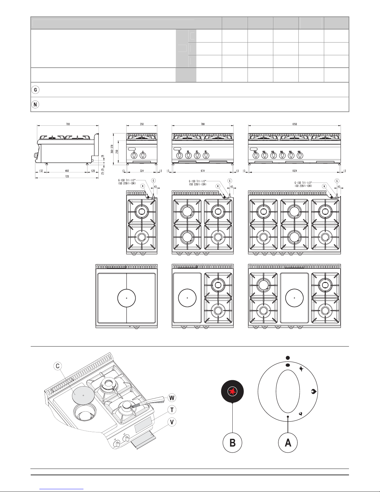
PC35G7 PC70G7 PC105G7 PCP70G7 PCP105G7 PPC70G7
L 350 700 1050 700 1050 700
P 700 700 700 700 700 700
Dimensioni esterne - External dimensions – Außenmaße - Внешние
разм. - Dimensions extérieures - Dimensiones externas.
mm
H
280 280 280 280 280 280
Potenza installata - Installed power – Nennleistung – Установленная
мощность - Puissance installée - Potencia instalada.
kW
10.5 19.5 30 15
22.8 9
Attacco gas - Gas inlet connection – Gasanschluss - Вход газа - Arrivée gaz - Entrada gas
G-ISO 7/1 – 1/2"
ISO 228/1 – (DK)
Morsetto equipotenziale - Unipotential earthing connection – Potentialausgleich - Эквипотенциальная клеммная коробка - Vis équipotentiel - Tornillo equipotencial
Fig.1 - Abb.1 - рис.1
Fig.2 - Abb.2 - рис.2 Fig.3 - Abb.3 - рис.3
IV 5410.263.00
Fig.4 - Abb.4 - рис.4 Fig.5 - Abb.5 - рис.5
- PPC70G7 -
Fig.6 - Abb.6 - рис.6
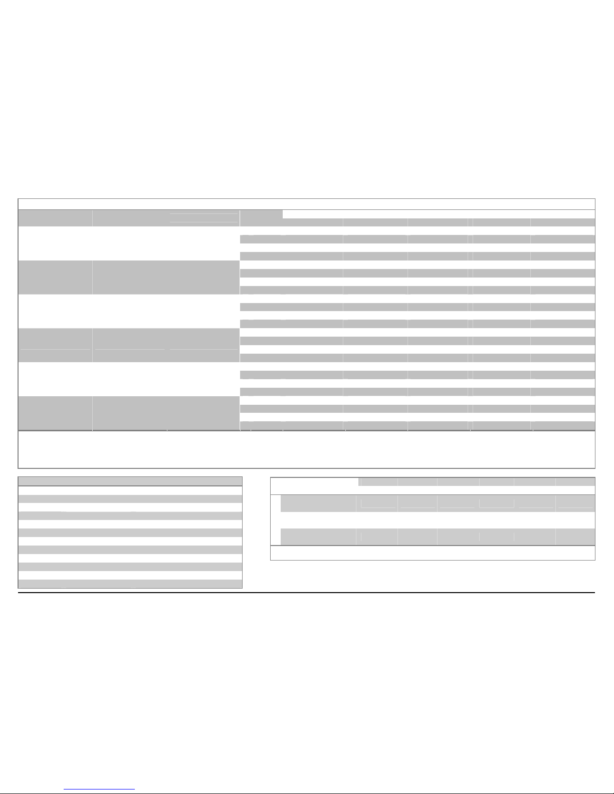
DATI TECNICI - TECHNISCHE DATEN - TECHNICAL DATA - DONNEES TECHNIQUES - DATOS TÉCNICOS 5410.263.00
▲- Brennerdüse - Burner nozzle - Макс.поз. - Injecteur du brûleur - Inyectores de los quemadores. ▼- Kleinstellschraube - Minimum adjusing screw - Мин.поз. - Vis de réglage minimum - Tornillo de regulación del mínimo
□ - Zündbrennerdüse - Pilot burner nozzle - Пламя - Injecteur de la veilleuse - Inyectores del piloto.
☼ - Warmhalteplatte - Heating plate - Плитка - Plaque chauffante - Plancha
H - Aria primaria - Primärluft Abstand - Первычный воздух - Primary air - Air primaire - Aire primario
T1. Tabella ugelli – Düsentabelle - Таблица форсунок - Nozzle table - Tableau des injecteurs - Tabla de los inyectores
Bruciatore (Brenner, burner, горелка, brûleur, quemador) ½ PIASTRA ☼ PIASTRA
CATEGORIA
(Kat.;Cat.)
P
[mbar]
GAS
Dim.
1/100 mm 3.3 kW 4.5 kW 7.2 kW 4.5 kW 9 kW
▲ MAX 130 155 200 155 220
▼ MIN REG. REG. REG. REG. REG.
□ PILOTA 35 35 35 35 35
2E;2E+;2H 20 G20
H [mm] 10 14 14 12 11
▲ MAX 85 105 130 105 140
▼ MIN 55 65 80 65 85
□ PILOTA 20 20 20 20 25
3+;3B/P+ 28-30/37 G30/G31
H [mm] MAX MAX MAX MAX MAX
▲ MAX 80 90 115 90 130
▼ MIN 50 55 70 55 70
□ PILOTA 20 20 20 20 25
3B/P 50 G30/G31
H [mm] MAX MAX MAX MAX MAX
▲ MAX 150 170 225 170 250
▼ MIN REG. REG. REG. REG. REG.
□ PILOTA 35 35 35 35 35
2LL 20 G25
H [mm] 9 12 12 10 9
▲ MAX 135 165 215 165 240
▼ MIN REG. REG. REG. REG. REG.
□ PILOTA 35 35 35 35 35
2L 25 G25
H [mm] 9 12 12 10 9
▲ MAX 140 165 220 165 240
▼ MIN REG. REG. REG. REG. REG.
□ PILOTA 35 35 35 35 35
2S 25 G25.1
H [mm] 9 10 11 9 9
Cat. (kat.) P Paese (land - country - pays - país)
I2E
20 mbar LU,PL
I2E+
20/25 mbar BE
I3+
28-30/37 mbar BE,LU
I3B/P
28-30 mbar NL,NO,CY,MT
II2E+3+
20/25, 28-30/37 mbar BE,FR
II2ELL3B/P
20, 50 mbar DE
II2H3+
20, 28-30/37 mbar ES,GB,GR,IE,IT,PT,SK
II2H3B/P
20, 28-30 mbar BG,DK,EE,FI,LV,LT,CZ,SE,SI
II2H3B/P
20, 50 mbar AT,CH
II2L3B/P
25, 28-30 mbar NL
II2S3B/P
25, 30 mbar HU
II2S3B/P
25, 50 mbar HU
PC35G7 PC70G7 PC105G7 PCP70G7 PCP105G7 PPC70G7
kW
10.5 19.5 30 15 22.8 9
Metano (G20)
(Hi = 9.45 kWh/m3) m3/h
1.11 2.06 3.17 1.59 2.41 0.95
Metano (G25 - G25.1)
(Hi = 8.13 kWh/m
3
) m3/h
1.29 2.40 3.69 1.84 2.80 1.10
Consumo *
GPL (G30)
(Hi = 12.68 kWh/kg) kg/h
0.83 1.54 2.37 1.82 1.79 0.71
* Gasverbrauch - Gas consumption - Consommation du gaz - Consumo de gas

GB / IE - 1 5410.263.00
Part 1 Installation
GAS COOKTOPS
General Instructions
The appliance described in this manual has been built to meet UNI
EN 203 and UNI EN 437 standards.
This appliance has been designed exclusively for cooking food, any
other use is considered improper. It should only be used by qualified
personnel in professional kitchens.
The unit must never be left unattended when it is being used! The
appliance should be checked once a year by a qualified technician.
Switch the appliance off in the case of a failure or malfunction.
The appliance should be installed under an extractor hood f or removing any cooking fumes.
Care must be taken when using the appliance because the cooking surfaces are very hot.
The appliance must be installed, connected and serviced properly by qualified personnel according to the regulations and
directives in force in the country where it is installed, as well as the instructions in this manual.
Unit characteristics
This instruction manual refers to the installation and use of the
Category II2H3+ gas cooktops.
The self-adhesive polyester data plate "T" (fig.2) is behind the
control panel (inside the appliance).
It contains the following information:
Model PC35G7 PC70G7 PC105G7
Serial number: xxxxxx
Category: II2H3+
Year of construction: XXXX
Nominal thermal capacity: 10.5 kW 19.5 kW 30 kW
Type of construction: A
Test base: UNI EN 203-1
Connection pressure:
G30
G20
28-30/37 mbar
20 mbar
Consumption:
G30
G20
0.83
1.11
Kg/h
m
3
/h
1.54
2.06
Kg/h
m3/h
2.36
3.17
Kg/h
m
3
/h
The supplementary plate is also made of self-adhesive polyester and
is affixed near the data plate; it contains all information regarding the
appliance.
Both the appliances have a fitting for gas connection. The "G" gas
distribution network connection (fig.1) meets ISO 7/1 and ISO 228/1
(DK) standards with a ø ½” connection, situated at the back of the
machine.
Model N. of burners Type
PC35G7 2 Burner
PC70G7 4 Cooker
PC105G7 6 Cooker
PCP70G7 2+1 Cooker + hot plate
PCP105G7 4+1 Cooker + hot plate
PPC70G7 1 Hot plate
The structure of the appliance is made of stainless steel, the burners
are made of cast iron and the oven is made of stainless steel. All
models have adjustable feet.
The main gas pipe is made of galvanised steel. The pipes between
the tap and burner are made of copper.
WARNING! Install a shut-off cock in the line between the
appliance and the gas distribution network.
Connection to the distribution network
Before you install the appliance, make sure that the
gas company has authorised the installation,
compare the data relevant of the appliance (data
plate) with the local supply.
Remove the packaging from the appliance as well as the protective
plastic sheet, and, if necessary, remove traces of glue with a suitable
solvent. To dispose of the packaging, follow local directives (for more
details refer to the chapter “ECOLOGY AND THE ENVIRONMENT”.
Prior to connecting the unit to the gas network, check the data plate
to see if the unit has been set and tested for the type of gas supplied.
If the gas type indicated on the data plate is not the same as that
supplied, please refer to the paragraph “CONVERSION AND
ADAPTATION”.
Connect the appliance to the gas distribution network using metal
pipes with a suitable diameter; install a homologated on/off cock
between the appliance and the distribution network. If flexible pipes
are used they must be made of stainless steel according to the
standards in force. When installing the appliance, all the regulations
in force must be observed, such as:
■ UNI-CIG 8723 safety standard, Act n.46 of the 5th of March 1990
and circular n.68.
■ Regional and/or local regulations, such as building codes;
■ Accident prevention regulations in force;
■ Fire prevention regulations;
■ Applicable I.E.C. regulations.
We recommend installing the appliance in a well-ventilated
environment, or under an extraction hood to remove the fumes or
vapours produced during the cooking cycle.
The appliance can be installed alone or in line.
Respect a minimum distance of 80mm between the appliance and
any walls made of flammable material, partitions, kitchen furniture or
nearby equipment.
The contact surfaces must be covered with non-combustible heat
insulating material.
The appliance must not be installed near heat sources, the ambient
temperature in the place where the appliance is installed must not
rise to over 50°C.
After installing the appliance check for any leaks in the fittings. Use
non-corrosive foam products, such as leak detection sprays, to look
for any leaks.

GB / IE - 2 5410.263.00
When checking for leaks do not use naked flames!
The manufacturer shall not be held responsible and the guarantee is void in the case of damage caused by negligence in
following the operating and installation instructions or by improper use. The guarantee is void in the case of connections which
have been made in a way which doesn't meet the current standards and fire-fighting regulations.
Evacuation of unburnt gases
This equipment doesn't need to be connected to a flue (A1type of construction), but we do recommend installing it under an extractor hood.
Checking the pressure
The distribution network pressure must meet the following
specifications:
ALLOWED
From 20/25 to 35/45 mbar
LPG
NOT ALLOWED
Below 20/25 above 35/40 mbar
ALLOWED
From 17 to 25 mbar
METHANE
H
NOT ALLOWED
Below 17 above 25 mbar
If the gas distribution network pressure on the installation site doesn't
meet the above values, inform the gas board and do not turn the unit
on until the cause and a solution have been found.
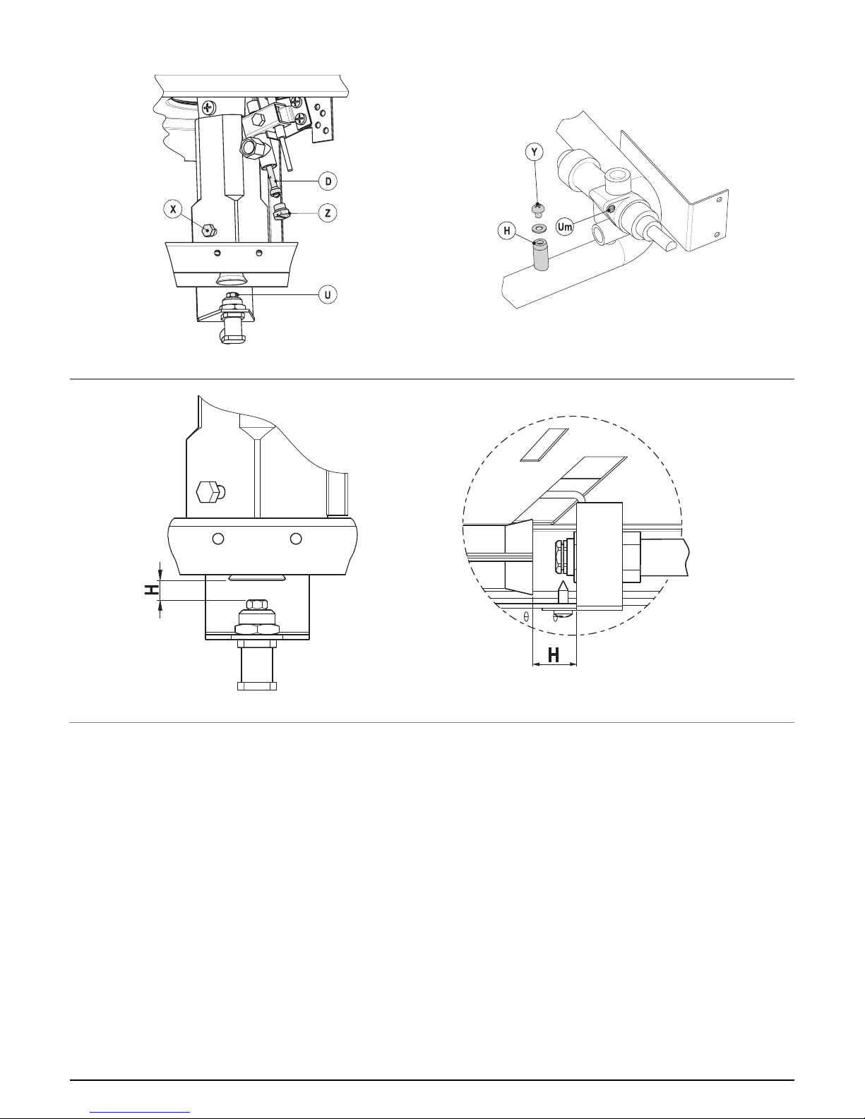
The distribution network pressure can be taken with a U manometer
(min. definition 0.1 mbar), connected to the pressure outlet behind
control panel “H” (fig.5).
1. Remove the control panel.
2. Remove screw "Y" and the sealing washer (fig.5) from the
pressure outlet and connect the manometer.
3. Turn the appliance on following the enclosed instructions and
check that the pressure is within the permitted pressure range.
4. Disconnect the manometer and replace screw "Y" and the
sealing washer (fig.5) in the pressure outlet.
5. Remove the control panel.

GB / IE - 3 5410.263.00
Part 2 Transformation and adaptation
To convert the appliance to another type of gas, e.g. from natural gas
to LPG, the nozzles of the main burner, by-pass and pilot light have
to be changed. All the nozzles are marked with a number that
indicates the diameter in 1/100 and are supplied in a bag.
After each conversion or adaptation, the unit must undergo an
operating test and the supplementary plate must be updated
according to the conversion or adaptation carried out.
Connections to the distribution network, installation, and maintenance of the appliance must only be carried out by qualified
technicians only, in observance of all applicable regulations!
Cooktop burner – Nozzles and air adjustment
BURNER:
1. Pull the knobs off.
2. Remove the control panel by unscrewing the fixing screws at the
rear, locate the burners.
3. Replace nozzle "U" (fig.4) with a suitable one for the new type of
gas indicated in the "MAX" nozzles table T1 section
Specifications.
4. Repeat the operation for all the burners.
ADJUSTING THE AIR:
5. Tighten the fixing screw "X" (fig.4).
6. Adjust the primary air by moving the bush a distance “H” (fig.6).
indicated in the nozzles table T1section Specifications.
7. Block the bush, by screwing in fixing screw “X” (fig.4)
PILOT LIGHT:
8. Unscrew and remove closing nut "Z" (fig.4)
9. Unscrew and replace the pilot nozzle (fig.4) with the type
indicated in nozzles table T1 section Specifications.
10. Replace and tighten closing nut "Z" (fig.4)
MINIMUM:
11. Unscrew and replace or adjust nozzle "Um" (fig.5) on the basis
of the indications in nozzles table T1 section Specifications.
12. Replace the control panel, tighten the fixing screws at the rear
and replace the knobs.

GB / IE - 4 5410.263.00
Part 3 Use
Turning the burner of the appliance on and off
COOKTOP BURNERS
Press and turn knob “A” (fig.3) from position “
” to " " keeping it
pressed in.
Light the pilot light with igniter "W" (fig.2) or a match. After the flame
has lit, hold the knob down for roughly 10 seconds (count to twenty);
so the thermocouple heats up and keeps the safety valve open.
HOT PLATE
In the models with a hot plate, lift cover "C" (fig.2) and follow the
previous instructions.
For model PPC70G7 light the pilot by pressing igniter button "B"
repeatedly (fig.3).
To light the main burner, turn the knob again until it reaches the
desired position.
Off
Flame on
pilot light
Burner MAX Burner min
Note: if the piezoelectric device cannot be used, you can light the
flame by hand using a match or a gas lighter.
TURNING THE BURNER OFF: Turn the knob from the position it is
in to the “
” position.
TURNING THE APPLIANCE OFF: Turn the knob to the “
“
position.
What to do if the unit is not going to be used for a long time
Turn the gas shut-off cock installed upstream off. Clean the
appliance with soapy water, rinse, dry carefully and apply a light
layer of liquid paraffin.
Malfunctions
Malfunctions do not always depend on the quality of the components
used. These appliances are manufactured using top quality
components. Failures may be caused by voltage surges, or dust and
dirt in the operating components.
In any situation where improper functioning of the appliance is
suspected, turn it off and DISCONNECT IT FROM THE MAINS. Call
the authorised repair service.
Unauthorised persons should never attempt to repair the appliance, or carry out maintenance. Tampering with the appliance
voids the warranty!
Operational checks
Before the unit is delivered to the user the following checks must be
carried out.
THERMAL CAPACITY
Check that the pressure and type of gas supplied where the unit is to
be used is the same as that indicated on the plate. If it is not, the unit
must either be converted or adapted. In this case please refer to the
paragraph: “Conversion or Adaptation”.
Check that the right nozzles have been installed. Refer to the nozzle
table and check that the nozzles indicated in the table are the same
as those installed on the unit.
An additional check of thermal capacity entails verifying the gas
consumed with the volumetric method: start the burner and after
approximately 10 minutes (in working conditions) check that the gas
flow (in m
3
/h or in kg/h) corresponds to that in the nozzle table.
APPEARANCE OF THE FLAME
The flame should be blue and there should be no yellow dots in it; it
must be stable at its base.
If the colour of the flame tends towards yellow it means the primary
airflow is not adjusted properly. If the primary airflow is too fast the
flame will be short and tend to burn above the burner.
The appearance of the flame must also be checked 15 minutes after
the appliance has been running at full power. The flame must remain
stable even when passing quickly from minimum to maximum.
USER'S INSTRUCTIONS
The user must be trained on the correct use and functions of the
appliance. We would like to point out that any alterations made to the
room where the unit is installed could influence the amount of air
used for combustion and for this reason the appliance must be
checked again. When these checks have been done, test the unit for
leaks.
Replacing parts
Only qualified personnel should replace faulty parts. Prior to
commencing any kind of work, disconnect the unit from the gas
distribution network. After having removed the control panel, all the
functional parts of the appliance are easily accessible.
Only order spare parts from the manufacturer or an authorised reseller.

GB / IE - 5 5410.263.00
Part 4 Maintenance and cleaning
Cleaning and care of the appliance
WARNING! The unit must be cold to clean it.
Keeping the appliance clean is very important for a long and troublefree working life.
The removable parts, for example drawer "V" (fig.2) should be
washed separately with warm water and detergent, then rinsed in
running water.
The steel parts may be cleaned with a damp cloth and with a nonabrasive detergent and then dried by using a soft, dry cloth. For very
resistant stains, use hot water and vinegar.
Do not use harsh or abrasive detergents to clean the stainless steel
parts. Iron cleaning pads should not be used as they cause the
formation of rust. For the same reason, avoid contact with ferrous
materials.
When cleaning, avoid using abrasive paper or cloth; instead and only
in special cases you can use pumice stone powder; we recommend
using sponges (ex. Scotch) to remove stubborn deposits. You can
also use common sprays for cleaning ovens and grills to remove
stubborn deposits. If spray products are used, follow the
manufacturer’s instructions.
Maintenance
The appliance needs no specific maintenance besides normal cleaning; we do however suggest having it checked once a year by the
assistance centre for which, we recommend drawing up a maintenance contract.
Safety precautions
REMEMBER THAT THE APPLIANCE:
■ Must never be left unattended when it is being used!
■ When the unit is switched on, its surfaces get very hot so please
take great care!
■ The appliance is intended for professional use and therefore
only qualified personnel should use it!
■ Installation as well as any conversion or adaptation to a different
type of gas must be carried out in accordance with current laws
and only by qualified and authorized personnel.
■ At least once a year have the appliance checked by qualified
personnel.
■ All the parts that come into contact with oil or fat during use,
should be cleaned regularly as indicated in the chapter
“Cleaning and Care”.
FIRE:
In the case of fire, close the shut-off cock to cut off the gas supply
immediately, then use a suitable fire extinguisher to fight the fire.
The Manufacturer declines any responsibility for damage caused by improper or incorrect installation or maintenance of the appliance, or
failure to observe safety regulations!
Ecology and environment
Our appliances are studied and optimised, with lab tests, to provide
high performance and yields. However, to keep energy consumption
low (electricity, gas and water), we suggest not using the appliance
for any length of time if it is empty or in conditions that compromise
optimum yield.
All packaging materials are environment-friendly. They can be kept
without problem or burnt in a waste incinerator plant. The plastic
components that can be recycled are:
■ Polyethylene: external packaging material and/or pluribol film
■ Polypropylene: straps
■ Polystyrene foam: corner pieces, sheets and protection blocks
At the end of the appliance’s useful life, dispose of it properly.
90% of each appliance is made of metal (stainless steel, iron,
aluminated sheet, etc.) hence it can be recycled by the relative
recycling organisations in compliance with the standards in force in
your country.
Prepare the appliance for disposal, so it cannot be used any more,
by removing the power cable and any locks so that no one can get
locked inside accidentally.

08/2005 DISEGNI / DIAGRAMS - A 5410.263.00

08/2005 DISEGNI / DIAGRAMS - B 5410.263.00

08/2005 DISEGNI / DIAGRAMS - C 5410.263.00

08/2005 DISEGNI / DIAGRAMS - D 5410.263.00
TAB.A – Cock nozzle
ø RIC.CODE
0.50 01207
0.55 01208
0.65 01209
0.70 01210
0.80 00582
0.85 50012
REG. 50022
MODEL:
PC35G7
PC70G7
PC105G7
PCP70G7
PCP105G7
PPC70G7
TAB-B – Pilot nozzle
ø RIC.CODE
0.20 00435
0.25 01211
0.35 00436
MODEL:
PC35G7
PC70G7
PC105G7
PCP70G7
PCP105G7
PPC70G7
TAB-C – Top burner nozzle
ø RIC.CODE
0.80 01188
0.85 00390
0.90 00391
1.05 00979
1.15 01189
1.30 01190
1.35 01191
1.40 01192
1.50 01193
1.55 01194
1.65 01195
1.70 01196
2.00 01197
2.15 01198
2.20 01199
2.25 01200
MODEL:
PC35G7
PC70G7
PC105G7
PCP70G7
PCP105G7
TAB-E – Hot plate nozzle
ø RIC.CODE
1.30 01202
1.40 00588
2.20 01205
2.40 01206
2.50 00590
MODEL:
PPC70G7

Il costruttore si riserva il diritto di modificare senza preavviso, le caratteristiche delle apparecchiature presenti in questa pubblicazione.
The manufacturer reserves the right to modify the appliances presented in this publication without notice.
Der Hersteller behält sich das Recht vor, die in dieser Broschüre vorgelegten Geräte ohne Voranzeige zuändern.
Фабрика оставляет за собой право без предупреждения изменять характеристики оборудования, описываемого в данной инструкции.
Le Fabricant se réserve le droit de modifier sans préavis les caractéristiques des appareils présentés dans cette publication.
El Fabricante se reserva el derecho de modificar sin previo aviso las características de los aparatos presentados en esta publicación.
 Loading...