

TECNOEKA EKF 1664 UD, EKF 2011 UD Use And Instruction Manual
USE AND INSTRUCTION MANUAL
MOD. EKF 1664 UD - EKF 2011 UD
rev. 0
TECNOEKA S.r.l.
Via Marco Polo, n.11 - 35010 Borgoricco (Padova) Italy
Tel. +39.049.9300344 – +39.049.5791479 Fax +39.049.5794387
www.tecnoeka.com E-mail: info@tecnoeka.com
_______________________________________________________________________ use and instruction manual
pag 2 _________________________________________________________________________________________
CE DECLARATION OF CONFORMITY
Annex II A, of Directive 2006/42/CE
Manufacturer's name
TECNOEKA Srl
Manufacturer's address
Via Marco Polo, 11 - 35010 Borgoricco (PD)
Name of the person in
charge of the technical file
Lorenzo Minotto
Address of the person in
charge of the technical file
Via Marco Polo, 11 - 35010 Borgoricco (PD)
Product type
Electronic oven
Purpose of the product
Cooking food
Model
EKF 1664 UD – EKF 2011 UD
TECNOEKA Srl declares that the above mentioned products comply with all provisions
pertaining to the following directives:
Low voltage directive 2006/95/CE end of validity 20/04/2016
Low voltage directive 2014/35/UE valid from 20/04/2016
Electromagnetic compatibility directive 2004/108/CE end of validity 20/04/2016
Electromagnetic compatibility directive 2014/30/UE valid from 20/04/2016
TECNOEKA Srl declares that the above mentioned products comply with the following
harmonised directives:
EN 60335-1 ; EN 60335-2-42
EN 55014-1 ; EN 55014-2 ; EN 61000-3-2 ; EN 61000-3-3 ;
EN 62233
TECNOEKA Srl declares that the above mentioned products also comply with the
following directives:
Machinery directive 2006/42/CE;
General product safety directive 2001/95/CE;
Directive restricting the use of hazardous substances in electrical and electronic equipment
2011/65/CE;
Directive on waste of electrical and electronic equipment 2012/19/UE.
TECNOEKA Srl declares that the above mentioned products comply with
(CE) Regulation 1907/2006
Borgoricco, 02/02/2016.
_________________________________
Board Representative Signature (Lora Cristina)

Electric Oven rev.0________________________________________________________ EKF 2011 UD – EKF 1664 UD
_________________________________________________________________________________________ pag 3

_______________________________________________________________________ use and instruction manual
pag 4 _________________________________________________________________________________________
Index
1.
Technical service
2.
General warnings
3.
Technical specifications
4.
Instructions for the installer
5.
Use instructions (for the user)
6.
Residual risks (for the user)
7.
How to use the control panel
8.
Oven cooking
9.
Cleaning
10.
Maintenance
11.
Possible faults
12.
Technical service
13.
Informations to the consumers
14.
Wiring layout
15.
The Warranty

Electric Oven rev.0________________________________________________________ EKF 2011 UD – EKF 1664 UD
_________________________________________________________________________________________ pag 5
1. Technical service
A technical check-up once or twice a year helps prolong the life of the appliance and
guarantees better operation.
Make sure that assistance is carried out solely and exclusively by qualified personnel.
For any spare parts orders or for any information about the appliance, always mention the serial
number and model (data indicated on the "technical data" plate at the rear of the oven).
2. General warnings
Very important!: keep this instruction book together with the appliance for future consultation.
These warnings were drafted for your safety and for that of others. Please read them carefully
before installing or using the appliance:
- If, on receipt of the goods, the packaging is damaged, write the following on the delivery
note: “I REVERSE THE RIGHT TO CONTROL THE GOODS”, specify the damage and get
the driver to sign in acceptance; send a claim in writing to the seller within 4 calendar
days from the date of receipt. No claim shall be accepted after such period.
- The appliance is intended for professional use and must be utilised by qualified personnel
trained to use it.
- Any modification which may be necessary on the electrical system to enable installation
of the appliance, must be carried out solely by competent personnel.
- It is dangerous to modify or attempt to modify the characteristics of this appliance.
- Never clean the appliance with direct water jets, because, if any water enters, it could
limit the machine's safety .
- Before doing any maintenance or cleaning jobs, disconnect the appliance from the
electrical mains and allow it to cool.
- Do not attempt to carry out the periodic controls or any repairs by yourself. Contact the
nearest Service Centre and use only original spare parts.
N.B.: Improper or incorrect use and failure to observe the installation instructions shall release
the manufacture from all responsibility. In this connection, the directives in the
"POSITIONING" paragraph must be strictly observed.
_______________________________________________________________________ use and instruction manual
pag 6 _________________________________________________________________________________________
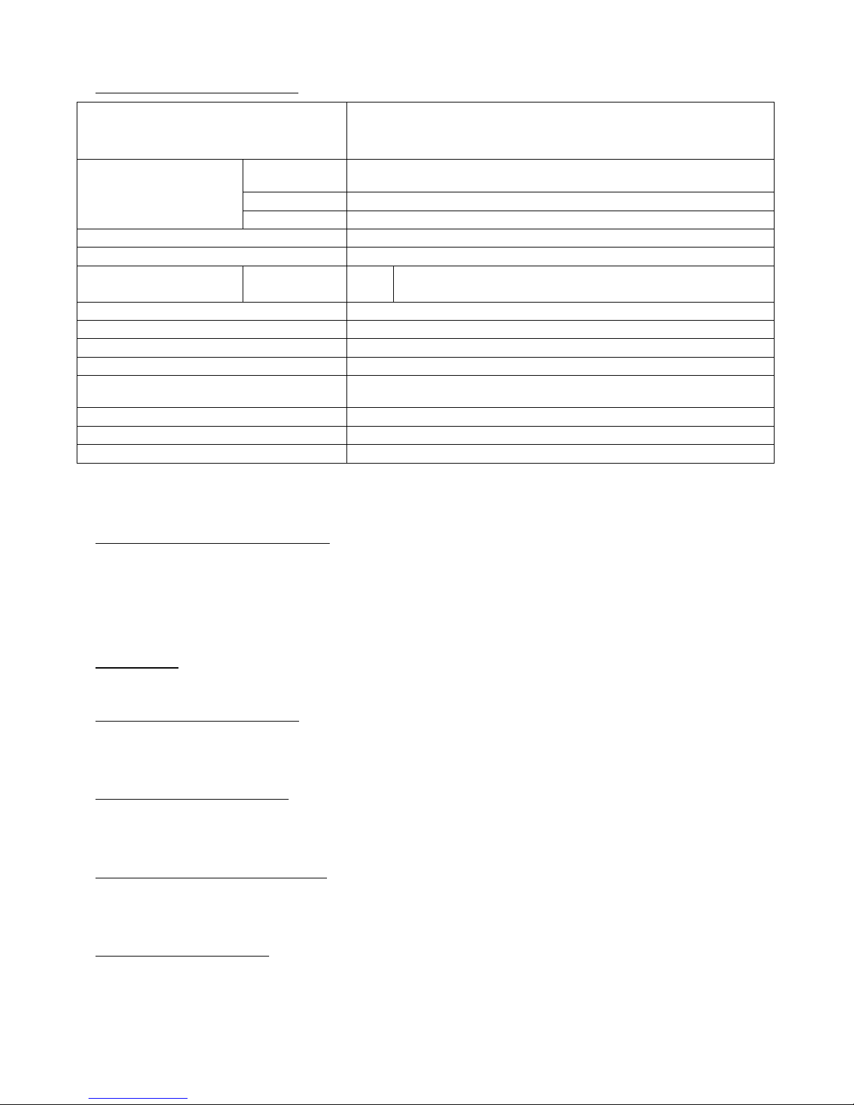
3. Technical specifications
Modd.
EKF 1664 UD
EKF 2011 UD
Dimensions of
appliance
height
(with feet)
cm 192
width
cm 98,5
depth
cm 103
Weight (Kg)
244,5
Maximum load per tray:
Kg 4
Electrical power:
Convection
resistors
5
kW 28,5
Convection heating element (kW)
30
Class
I Degree of protection against humidity
IPX3
Water pressure kPa 100 – 200
Power supply voltage (V)
400V 3N 50 Hz
Power cable diameter:
5G 10 (5 x 10 mm2)
Type of cable
H07RN-F
Connecting electric cable: Tipo : Y
The noise level of the appliance in operation is below 70 dB (A).
4. Instructions for the installer
The following instructions are aimed at the skilled installer for them to perform installation,
electrical and water connection operations in the most correct manner and according to the
safety regulations in force in the place of installation of the appliance.
The manufacturer shall not be liable for damage or harm to persons, pets or property arising
from installation errors. Nor are they responsible for any appliance breakage caused by faulty
installation.
4.1 Storage
In the event the appliance has been warehoused at temperatures below 0°C (maximum allowed
– 5°C), it must be brought back to a temperature of at least +10°C before operating it.
4.2 Transport of the appliance
During transport the appliance must be left in its packaging in order to protect it from any
external damage.
The weight of the appliance must also be taken into account in order to prevent overturning.
4.3 Unpacking the appliance
Remove packaging before installation. It consists of a wooden pallet supporting the appliance
and a cardboard casing protecting it. Ensure the appliance has not undergone any damage
during transport; otherwise immediately alert your dealer and/or carrier.
4.4 Removal of the protecting film
Before using the appliance accurately remove the special film protecting the stainless steel
components, avoiding to leave glue residues on the surfaces; if required, immediately remove
them using an appropriate solvent of non-flammable type.
4.5 Disposal of packaging
The packaging must be disposed of in strict compliance with the regulations in force in the
place of installation of the appliance. The various materials (wood-paper-cardboard-nylon-metal
staples) the packaging consists of must be suitably separated and delivered to the suitable
collection centres. In any case adhere to environmental protection regulations.

Electric Oven rev.0________________________________________________________ EKF 2011 UD – EKF 1664 UD
_________________________________________________________________________________________ pag 7
4.6 Placement
Check the place of installation ensuring transit areas (any doors and corridors) are sufficiently
wide (the dimensions of the appliance without pallet are shown in Fig.1).
The appliance must be installed in a well-aerated room with permanent vents.
The maximum working height, referred to the highest surface level, must be 1.6 metres from
the floor. After installing the appliance apply the suitable adhesive symbol (supplied) at a height
of 1.6 metres.
To assure accessibility and air circulation around the appliance, leave at least 50cm of space
between the left side and the wall (or other appliance), and at least 10 cm between the back
and the wall and between the right side and the wall (see Fig.1). It is strictly forbidden to
obstruct, even partially, the forced aeration vents on the left side, even for short periods of time.
Failure to comply with this explicit prohibition shall void any liability from the appliance's
manufacturer and immediately forfeit any warranty rights on the same, since its constructive
conformity has been deliberately impaired. For the same reason, do not place any appliances
that might produce heat sources and/or spray hot liquids (fryers) near the left side.
Should the appliance be installed near walls, shelves, tops and the like, these must be of the
non-flammable or heat-insensitive type; otherwise, they must be protected by adequate fire
retardant coating. In this connection it is indispensable to act in compliance with the fire
prevention regulations in force.
Cooking produces hot smoke and smells which are expelled from the suitable vent device at the
top of the appliance. It is recommended to place the appliance under an extraction hood or to
use the suitable TECNOEKA hoods, in order to convey the smoke to the outside.
The appliance must be positioned on a flat and level floor. After placement, ensure the
appliance is horizontally aligned. This check may be carried out by placing a "bubble level" on
the 4 top sides of its casing. Ensure the tray trolley is able to go in and out of the cooking
chamber easily, without rubbing against the lower surface, even when it is "fully loaded". In the
event this operation should not be possible, the appliance feet must be adjusted to lower it so
that the tray trolley may be moved properly. In any case, upon completing adjustment, ensure
the wheels of the tray trolley, inserted in the cooking chamber, are raised from the floor (not
more than 5 mm), and that the trolley is supported by the suitable guides at the bottom of the
appliance.
The tray trolley must be moved using the handgrip supplied. The handgrip must be inserted into
the suitable seats at the front of the trolley up to the "stopping point".
The tray trolley must be inserted inside the cooking chamber, freely sliding on the suitable
guides in the lower portion of the appliance.
Warning
Appliance malfunctioning may occur unless the tray trolley is correctly positioned.

_______________________________________________________________________ use and instruction manual
pag 8 _________________________________________________________________________________________
Electrical connection
The connection to the main supply must be in conformity with current legislation in force.
Before making the electrical connections, make sure that:
- the voltage and frequency values of the power supply system match the values on
the "technical data" plate affixed on the rear of appliance;
- the pressure relief valve and the system must be able to support the appliance load
(see the data on the technical rating plate;
- the power supply system must be equipped with an efficient earth connection
according to current regulations;
- with direct-to-mains connection, a multi-pole switch must be installed between the
appliance and the mains with a minimum opening between the contacts of the
overvoltage category III (4000 V), of a sufficient size for the load and conforming to
current regulations (e.g. an automatic magnetothermal switch);
- the multi-pole switch that is used for the connection must be easily accessible once
the appliance is installed;
- the yellow/green earth wire must not be disconnected by the switch;
- the supply voltage must not differ from the rated voltage level by ±10% when the
appliance is operating;
- make sure that after inserting the power supply cord into the terminal block it does
not come into contact with any of the cooking range's hot parts.
- if the supply cable is damaged then it must be replaced by the manufacturer or by
your technical support or by a qualified person to avoid any risk.
The appliance must be connected to an equipotential system after checking its efficiency
according to current regulations.
This connection must be made between different appliances using the special terminal marked
with . The equipotential lead must have a minimum diameter of 2,5mm2. The equipotential
terminal is on the rear of the appliance.
 Loading...