

ORIGINAL OPERATING AND INSTRUCTION MANUAL
MODD. EKF 1111G E UD – EKF 1064G E UD
rev. 0
CATEGORY II2H3B/P
DK
0705
TECNOEKA S.r.l.
Via Marco Polo, n.11 - 35010 Borgoricco (Padova) Italy
Tel. +39.049.9300344 – +39.049.5791479 Fax +39.049.5794387
www.tecnoeka.com E-mail: info@tecnoeka.com

TECNOEKA Srl _____________________________________________________________ use and instruction manual
CE
DECLARATION OF CONFORMITY
Annexed document II A, of directive 2006/42/EC
Manufacturer name
TECNOEKA Srl
Manufacturer address
Name of person responsible
for technical file
Address of person
responsible for technical file
Type of product
Purpose of product
Model
Via Marco Polo, 11 - 35010 Borgoricco (PD)
Minotto Lorenzo
Via Marco Polo, 11 - 35010 Borgoricco (PD)
Gas oven
Cooking food
EKF 1111G E UD – EKF 1064G E UD
TECNOEKA Srl hereby declares that the above-mentioned products meet all the relevant
requirements of the following directives:
Low voltage directive 2006/95/EC
Electromagnetic compatibility directive 2004/108/EC.
TECNOEKA Srl hereby declares that the above-mentioned products meet the requirements of the
following harmonized standards:
IEC EN 60335-1; IEC EN 60335-2-42
IEC EN 55014-1; IEC EN 55014-2; IEC EN 61000-3-2; IEC EN 61000-3-3; IEC EN 61000-4-2
IEC EN 61000-4-4; IEC EN 61000-4-5; IEC EN 61000-4-6; IEC EN 61000-4-11; IEC EN 62233
TECNOEKA Srl hereby declares that the above-mentioned products also meet the requirements of
the following directives:
Gas Appliances directive 2009/142/EC
Machinery directive 2006/42/EC;
General product safety directive 2001/95/EC;
Restriction of hazardous substances in electrical and electronic equipment (RoHS) directive
2002/95/EC;
Waste electrical and electronic equipment directive 2002/96/EC.
TECNOEKA Srl hereby declares that the above-mentioned products meet the requirements of
EC Regulation 1907/2006
_________________________________
Borgoricco, 25/05/2015.
X:\Sgq\PRODOTTI\1 - FORNI\FORNO GAS\LEka\MANUALI D'USO - Forno gas - LEka\Lingua Inglese\Linea
EKF\Manuali per Danimarca\Instruction manual EKF 1111G E UD - EKF 1064G E UD- DK - rev. 0.doc
page. 2 __________________________________________________________________________________________
Signature of a Representative of the Board of Directors
(Lora Cristina)
Convection gas oven rev. 0___________________________________ MODD. EKF 1111G E UD – EKF 1064G E UD
1 Descriptions and general warnings
1.1
General warnings
1.2 Data
-
plate and warning
-
plate
1.3 Technical specifications
2 General instruction
(for installation technician)
2.1 Storage
2.2 Transporting the oven
2.3 Unpacking the oven
2.4 Removing the protective film
2.5 Disposing
of the packaging
2.6 Positioning
2.7 Gas connection
2.8 Electrical connection
2.9 Connection to water mains
2.10
Water outlet
2.11
Thermal breaker safety devices
3 Start
-
up
(for installation technician)
3.1 Check
of nominal thermal capacity
3.2 Check of connection pressure
3.3 Adaptation to other gas
3.4 Injector replacement and adjustment of primary air
4 User instructions
4.1 General information
4.1.1
Residual risks
4.2 How to use the control panel
4.2.1
Control panel
5 Switching on
6 Operative mode
s
7 Cooking types
8 Door device
9 Black out
10 Communicating with the PC
11 Cleaning
11.1
General information
11.2
Cleaning the cooking chamber
11.3
Cleaning the door seal
11.4
Cleaning t
he door
11.5
Cleaning the external casing
11.6
Periods without use
12 Maintenance
12.1
General information
12.2
Changing the lighting lamp in the cooking chamber
12.3
Changing the door seal
12.4
Cleaning the fans
12.5
Resetting the thermal
breaker safety device
13 Possible faults
14 Possible alarms
15 Wiring layout
16 Technical assistance and original spare parts
16.1
Spare parts list
17 Informations to the consumers
18 The Warranty
19
Availability and supply of spare parts
Index
2.12
Disposing of the oven
_________________________________________________________________________________________ page. 3

TECNOEKA Srl _____________________________________________________________ use and instruction manual
Note 1:
The information provided in this manual are valid only for the oven’s models listed in the cover
and for the country whose initials are therein indicated with the category of membership.
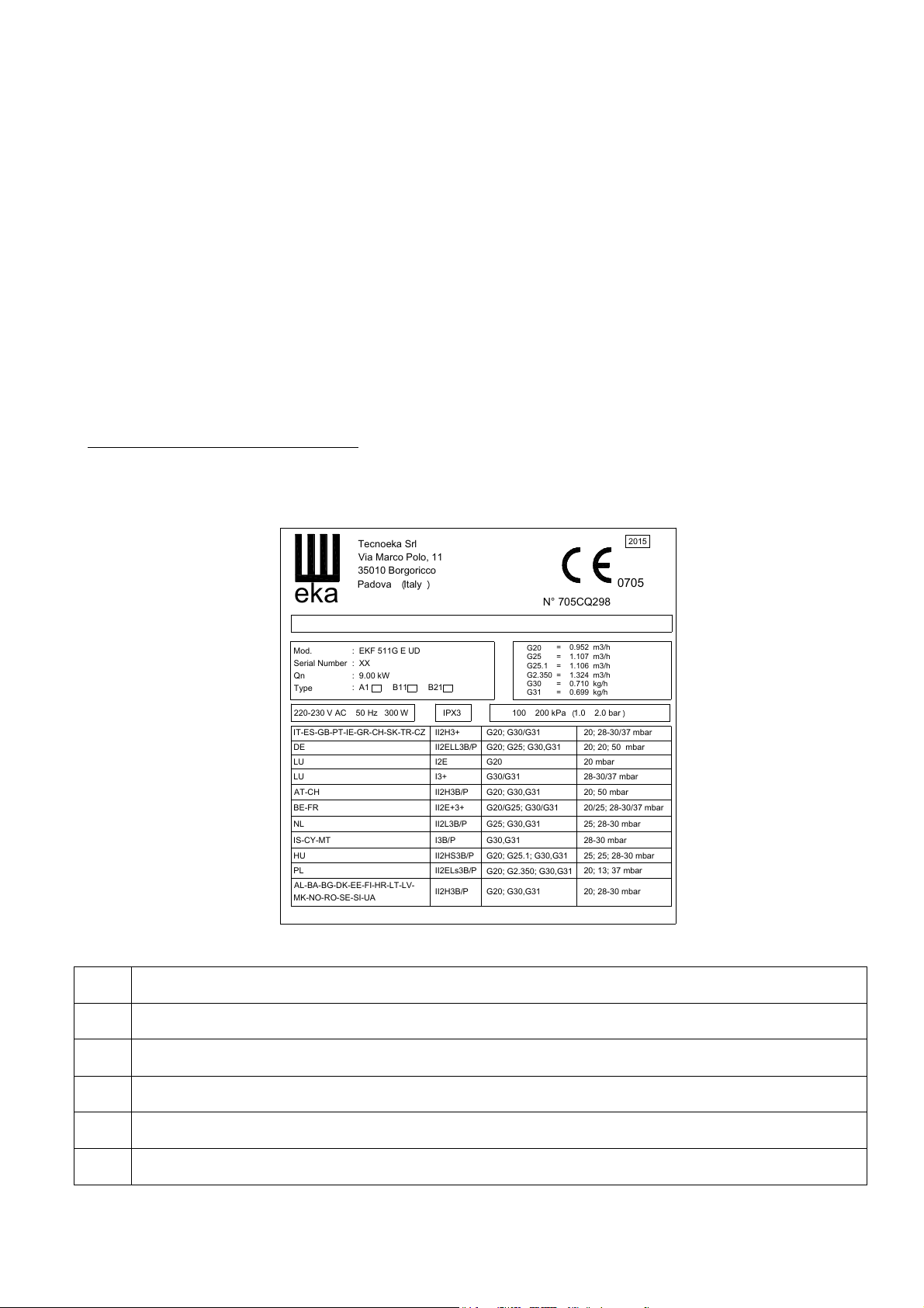
For European countries whose initials are present in the data plate on the left side panel (see
Fig. 1), the operating instructions will be provided in the official language with functional
adaptations to the country (as the additional injector for gas available and its conditions of
supply).
Note 2:
These instructions apply only if the EU country code is given on the nameplate of the oven. If
the code does not appear, you should refer to the technical instructions which will provide
necessary instructions regarding the adaptation of the unit to the conditions of use of other
non-EU countries.
1. Description and general warnings
The model convector oven bears (EKF 1064G E UD – EKF 1111G E UD) an official CE mark,
issued by a Notified Body, entrusted with and responsible for evaluating the observance of the
essential requirements specified by Gas Directive 2009/142/EC. The oven and the quality of the
production system are subjected to regular surveillance by means of inspection checks in order
to ascertain their conformity to the type certificate specified by the above mentioned Directive.
This appliance may be marketed in all the European countries whose abbreviated reference is
present on the technical data-plate. The appliance must be installed to conform with the local
laws on the installation of electrical-gas appliance for collective use, and shall include the
accessories and functional adaptations required in the destination countries, which are
described in the original language in the use and maintenance handbook.
The oven has an atmospheric burner and a heat exchanger for heating the cooking
compartment. Heat is diffused by an internal two-way fan. The parameters relative to cooking
(times, temperatures and climate) you set electronically and appear on the digital display.
It is possible to get steam inside the oven chamber. If the burner doesn’t switch on, a red block
light: it is possible to restart safely the ingnition of burner through the reset button. If the oven
chamber overheats, a safety thermostat blocks the gas delivery and the power to the oven is cut
off; it will be possible to switch it on again only manually. The device is located on the rear of
the unit.
1.1 General warnings
- If, on receipt of the goods, the
note:
“I REVERSE THE RIGHT TO CONTROL THE GOODS”
packaging
the driver to sign in acceptance; send a claim in writing to the seller within 4 calendar
days from the date of receipt. No claim shall be accepted after such period.
- Read this handbook carefully: it supplies information on safe use, installation and
maintenance. The purpose of this manual is to provide information to operators on the
essential prescriptions and criteria to ensure their own safety and prolong the oven’s
operating life. This manual must be read by all personnel authorised to work on the
machine before it is started up. It must be stored together with the machine for all future
consultation. If the manual becomes worn or is mislaid, ask for another copy directly
from the manufacturer. These instructions are valid only for countries whose abbreviated
reference appears on the cover of this manual and on the data-plate. In European
countries where marketing is possible, manuals in the official language shall be provided
with specific references to gas, pressures, categories and conditions for the connection.
In European countries where marketing is possible, manuals in the official language shall
be provided with specific references to gas, pressures, categories and conditions for the
connection.
Maintenance, adaptation to another type of gas, installation, and the functional check
-
must be performed only by qualified personnel authorised by the manufacturer. Install
page. 4 __________________________________________________________________________________________
is damaged, write the following on the delivery
, specify the damage and get
Convection gas oven rev. 0___________________________________ MODD. EKF 1111G E UD – EKF 1064G E UD
“Dieses Gerat muß nach geltenden Vorschriften angeschlossen und darf nur in einem gut belufteten Raum betrieben werden.
“L’appareil do
it être raccordé conformément aux normes en vigueur et il ne doit être installé que dans locaux bien aérés.
“El apparato debe ser con
ectado conforme a las normas vigentes y se tiene que instalar solo en locales bien aireados.
“The appliance must be connected accordin
g to the standards in force and must be installed only in well aired premises.
O aparelho deve ser ligado em conformidade com as normas vigentes e dev
e ser instalado somente em locais bem ventilados.
"L'apparecchio deve essere allacciato conformemente alle norme in vigore e deve es
sere installato solo in locali ben aerati.
the appliance in a suitable ventilated room and put it into operation while observing the
laws in force. Insist on original spare parts and, after replacing and/or adjusting a part,
such as primary air, make sure that it is sealed with paint to prevent any tampering. We
advise you to take out a maintenance contract.
- This appliance is designed for cooking or heating foods. Do not use it for other purposes;
all other uses are considered improper. The appliance is intended for collective and
professional use and must be utilised by personnel trained to use it.
- Before every oven cleaning or maintenance job, switch off electrical power, and shut off
gas and water supplies.
- The appliance is not intended to be used by children and/or persons with impaired
physical, sensory or mental abilities, or who lack experience or knowledge, unless they
are supervised by a person responsible for their safety, or who has been instructed on
N.B.: Improper or incorrect use and failure to observe the installation instructions shall release the
using the appliance.
manufacturer from all responsibility.
1.2 Data-plate and warning-plate
The technical data-plate (Fig.1) and the plate with the installation warnings (Fig. 2) are
permanently and visibly fitted on the rear panel of the oven. An additional plate – to be
removed with all packing material – is situated inside the packing.
Tecnoeka Sr
Via Marco Polo, 1
eka
Mod
.
Serial Number
Q
n
Typ
e
220-230 V AC 50 Hz 300 W
IT-ES-GB-PT-IE-GR-CH-SK-TR-CZ
D
E
L
U
L
U
AT-CH
BE-FR
N
L
IS-CY-M
H
U
P
L
AL-BA-BG-DK-EE-FI-HR-LT-LV-
MK-NO-RO-SE-SI-UA
35010 Borgoricc
Padova (Italy
: EKF 511G E U
: XX
: 9.00 k
: A1 B11 B2
T
l
o
)
IT ; G20 ; 2H ; 20 mba
DK ; G30,G31 ; 3B/P ; 28-30mbar
D
W
1
N° 705CQ298
r
G20
G25
G25.1
G2.35
1
IPX
3
II2H3
+
II2ELL3B/PG20; G25; G30,G31
I2E
I3+
II2H3B/
P
II2E+3+
II2L3B/PG25; G30,G3
I3B/P
II2HS3B/PG20; G25.1; G30,G3
II2ELs3B/
P
II2H3B/PG20; G30,G3
G30
G31
100
200 kPa(1.0
÷
G20; G30/G3
G20
G30/G31
G20; G30,G3
G20/G25; G30/G3
G30,G31
G20; G2.350; G30,G3
1
1
1
1
= 0.952 m3/
= 1.107 m3/
= 1.106 m3/
0
= 1.324 m3/
= 0.710 kg/
= 0.699 kg/
1
1
1
201
5
070
5
h
h
h
h
h
h
÷ 2.0 ba
r
)
20; 28-30/37 mbar
20; 20; 50 mba
20 mbar
28-30/37 mbar
20; 50 mbar
20/25; 28-30/37 mba
25; 28-30 mba
28-30 mba
25; 25; 28-30 mba
20; 13; 37 mbar
20; 28-30 mba
r
r
r
r
r
r
DE
FR
ES
GB
PT
IT
Bitte beachten Sie vor Inbetriebnahme des Gerates die Gebrauchs- und Wartungsanleitung.“
Faire attention aux instructions relatives á l’utilisation et l’entretien de l’appareil avant de le mettre en marche.“
Prestese especial atencion a las instrucciones para el luso y mantenimiento del apparato antes de ponerlo en marcha.”
It is recommended to follow the use and servicing instructions of the appliance before operating it.”
Deve-se prestar particular atenção às instruções para o uso e a manutenção do aparelho antes de pô-lo em funcionamento.
Si presti particolare attenzione alle istruzioni per l'uso e la manutenzione dell'apparecchio prima di metterlo in funzione."
Fig 1
Fig. 2
_________________________________________________________________________________________ page. 5
TECNOEKA Srl _____________________________________________________________ use and instruction manual
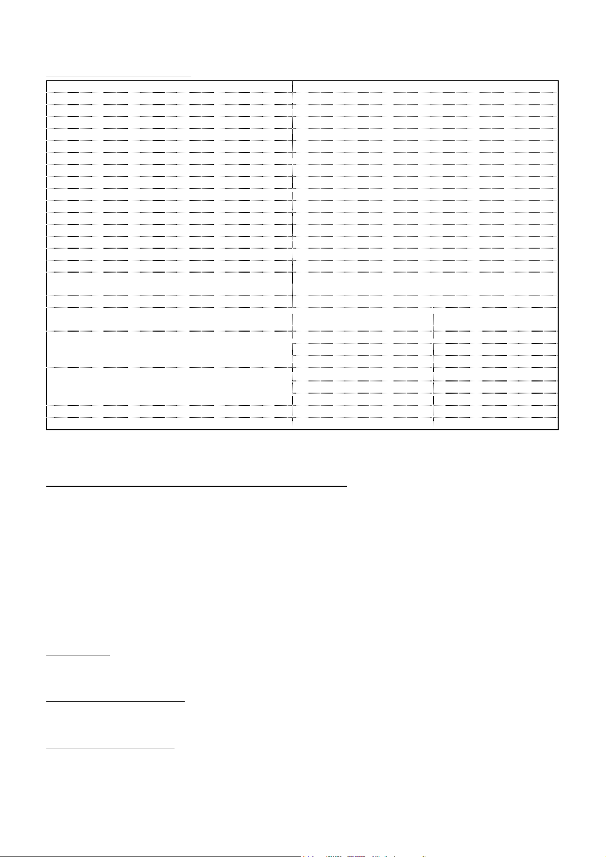
External overall dimension L x D x H
935 x 980
x 1388 mm
Weight
152 Kg
Nominal thermal capacity
17,50 kW
Tray maximal load (GN1/1)
4 kg
Total load (10 trays GN 1/1)
44 kg
ISO 7
-
1 gas union
1/2 “
Water union
3/4 “
Fume exhaustion vertical tube
Ø 150 mm; height
min. 10
00 mm
Appliance categor
y (for
Danimarca
) II2H3
B/P
Factory adjustment
Methane gas
G20 ,
20 mbar
Type of construction
B
/ B21
Electrical power
220-230
V ~
Electrical capacity
0,7 kW
Class
I
Power cable type
H07RN
-
F 3 x 1,5 mm
Connecting electric cable
Type Y
Liquid butane/propane gas
G30/G31 :
28-30 mbar
Water connection pressure
Max. 200 kPa (2,0 bar)
Gas consumption calculated at low heat value of
Hi
at
fume load
31.63 g/s
fume temperature
136.8 °C
fume pressure
-2.1 Pa
fume temperature
141.6 °C
fume
pressure
-2.3 Pa
Main injector diameter
G30/G31 :
220
G20 :
32
0
Primary air bush adjustment
G30/G
31 :
3
6 mm
G20 :
24 mm
1.3 Technical specifications
11
2
Gas connection pressure
15° and 1013 mbar
Parameters to the chimney B11 (Ø 150 mm, L=1 m)
(G20 20 mbar)
Parameters to the chimney B11 (Ø 150 mm, L=1 m)
(G30 28-30 mbar)
Table 1
G30 : 1,380 kg / h G20 : 1,852 m3 / h
The noise level of the appliance in operation is less than 70 dB (A).
Methane gas G20: 20 mbar
fume load 29.60 g/s
1/100 mm
1/100 mm
2. General instruction (for installation technician)
The installation technician must make sure that start-up conforms to current national
regulations. The appliance must be installed only by qualified personnel authorised by the
manufacturer. She must observe the safety regulations in force in the country where the
appliance is installed. All extraordinary maintenance jobs (possible adaptation to another type of
gas or replacement of parts) must be performed by qualified personnel having the necessary
professional qualifications. The protected devices and / or sealed by the manufacturer and that
are not intended for maintenance, adjustment, or adaptation to change of gas must not be
handled either by the installer or user. The seals that must be removed to change the gas must
be restored at the end of the adaptation. The manufacturer will not respond for damage to
people, animals and property due to installation errors. Likewise the manufacturer is not
responsible for breakage caused to the appliance by incorrect installation.
2.1 Storage
If the appliance has been stored in a warehouse at a temperature below 0°C (min. allowed is –
5°C), it should be brought to a temperature of at least +10°C before it is turned on.
2.2 Transporting the oven
During transport, the appliance must be left in its original wooden cage to protect it against
damage.
2.3 Unpacking the oven
Remove all the packaging before installation, which is formed of a wooden pallet that holds the
appliance and cardboard casing to protect it. Check that the appliance has not been damaged
during transport and if any damage is discovered immediately inform your retailer and/or the
haulier.
page. 6 __________________________________________________________________________________________

Convection gas oven rev. 0___________________________________ MODD. EKF 1111G E UD – EKF 1064G E UD
2.4 Removing the protective film
Before using the appliance, carefully remove the special protective film over the stainless steel
parts, without leaving any glue residue on the surfaces. If necessary, remove the residue at once
with a suitable non-inflammable solvent (e.g. acetone).
2.5 Disposing of the packaging
The packaging must be disposed of in accordance with current legislation in force in the place
where the appliance is installed. The various types of materials (wood – paper – cardboard –
nylon – metal staples) used for the packaging must be separated and delivered to the specific
waste disposal centres. In all circumstances the environmental protection regulations must be
strictly adhered to.
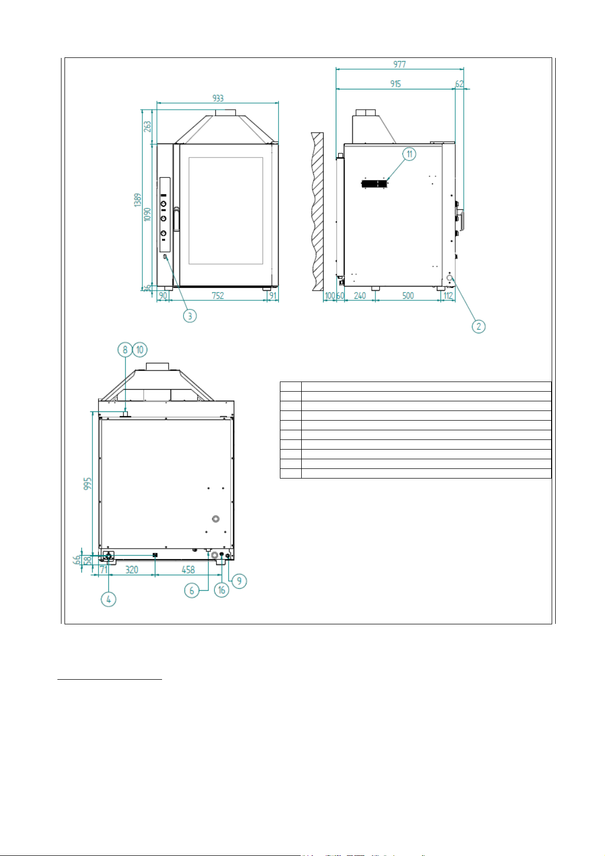
2.6 Positioning
Check the place where the appliance will be installed to ensure that the passages (doors and
corridors) are wide enough (the appliance measurements are given in Fig. 3).
The appliance must be installed in a well ventilated room with permanent ventilation openings –
if possible, it should be placed under an exhaustion hood ensuring complete evacuation of
burned gasses produced during baking. Locate the oven on a table or similar support. We
advise to use the support given by the manufacturer; otherwise you must consider the weight
of the oven. Never on the floor.
The maximum working height, referred to the highest surface level, must be 1.6 meters from
the floor. After installing the appliance apply the suitable adhesive symbol at a height of 1.6
meters. For easier access and to allow the air to circulate freely around the appliance, leave at
least 50 cm between the left side and the wall (or other appliances), and at least 10 cm
between the back and the wall and the right side and the wall (see Fig. 3). The natural
ventilation that is needed to ensure efficient working for the oven is through the openings on
the walls of the outer covering (left side and back). Consequently, it is strictly forbidden to
obstruct these aeration openings, even partially and even for short periods.
Failure to observe
this specific prohibition, shall release the manufacturer from all liability for the appliance and
shall immediately cancel any guarantee rights for the said appliance,
because its constructive
conformity has been voluntarily compromised.
For the same reason, do not position equipment with a source of heat on the left hand side of
the oven; in fact if ambient temperature on that side becomes too high, the oven switches itself
off for safety reasons
If the appliance is installed near walls, tops, shelves or other similar items, they must not be
inflammable or sensitive to heat, otherwise they must be protected by a suitable fireproof
covering. In all cases, all fire prevention standards must be strictly adhered to.
With regards to the methods of discharging combustion fumes and in compliance with the
provisions of the local legislation for the installation of gas equipment, this oven can be
classified and therefore installed as follows:
Type A1 Installation: drawing the comburent air and discharging flue gases directly into the
installation room. This installation requires the working environment to be kept wholesome by
emptying the foul air and drawing fresh air through wall fans or extraction equipment.
Type B
Type B
Installation: installation required under extraction equipment.
21
Installation: discharging the flue gases out of the installation room with a draught-
11
diverter compatible with a vertical tube (diam. 150 mm) making the discharge of the flue gases
into the extraction unit or directly into the building flue easy.
Since flue gases can reach high temperatures, pay particular attention not to overheat any
temperature sensitive elements (extraction equipment filters, electrical cables, etc.).
For the details regarding the installation (for instance minimum sections of ventilation, storing of
the gas canisters, etc.) see the applicable regulations in force in the country of destination. Pay
particular attention so that the volume of air required for the combustion is not obstructed in
any way by objects placed under or around the unit.
_________________________________________________________________________________________ page. 7

TECNOEKA Srl _____________________________________________________________ use and instruction manual
The type of installation of ovens (A1, B11 or B21) is subject to national rules; for that reason,
the technician in charge must comply with national regulations and then classify the oven by
placing a cross on the box on the data plate (A1-B11-B21).
The classification on the method of the flues depends on the thermal capacity of the device, on
its type, the volume of the room and the type of ventilation present (forced or natural); typically
the sections of inflow air and exhaust fumes / vapor depend, among other things, by the total
thermal load of equipment present in the room (technical area).
Tecnoeka ovens are equipped with a device to let the fumes out fixed on the roof (see Fig. 3); it
acts as a draft diverter / windproof in case of installation B11 provided with direct connection to
the flue by means of a vertical pipe; However,
the device is an integral part of the oven, and
should never be removed, regardless of the type of installation.
Installation / connection layout
page. 8 __________________________________________________________________________________________
Convection gas oven rev. 0___________________________________ MODD. EKF 1111G E UD – EKF 1064G E UD
2 SERIAL PORT
3 PLUG FOR CORE PROBE
4 WATER OULET TUBE (DN 30)
5 CLEANING SYSTEM WATER INLET (THREADED ELECTROVALVE 3/4")
6 SOFTENED WATER INLET (THREADED ELECTROVALVE 3/4")
8 STEAM EXHAUST
9 CABLE GLAND FOR POWER SUPPLY
10 WARNING HOT SURFACE
11 DO NOT OBSTRUCT VENTS
16 GAS INLET (THREADED JOINT 1/2")
Fig. 3 (Dimensions in mm.)
2.7 Gas connection
Before installing, make sure that the oven is designed for use with the available gas. If it is not,
consult paragraph “Adaptation to other gas” or contact the manufacturer’s technical assistance
service. Connection to the gas mains must be made according to the current national norm and
subsequent amendments.
The oven gas connection is R 1/2; this entry section must not be reduced.
Connection to the gas supply line must be made by using rigid or flexible pipes (maximum
length 1,5m) , exclusively in metal, with diameters in proportion to the power of the appliance
and the length of the pipe route. Make sure that the pipe does not pass close to the hot areas
and that it is not subjected to torsion and traction stresses. Install a rapid ON/OFF tap between
_________________________________________________________________________________________ page. 9

TECNOEKA Srl _____________________________________________________________ use and instruction manual
the gas mains and each appliance, in a position facilitating tap opening and shutting operations.
After installing the appliance, run a tightness test on the entire gas circuit, using a leak-detector
spray or other non-corrosive foam generating substances (do not use flames for this operation).
The unions of the copper pipes must be made by using mechanical couplings without seals.
2.8 Electrical connection
Connection to the electrical mains must be made according to the current legal regulations.
Before making the electrical connection, make sure that the voltage and frequency shown on
the rating-plate match those of the electrical supply system and that the latter is provided with
an efficient earth connection. The power cable used must not have lower characteristics than:
rubber insulated type H07RN-F with diameter of 3 x 1,5 mm2. If connection to the electrical
mains is permanent, a multi-core protective switch of adequate capacity must be installed, with
contact opening distance of the overvoltage category III (4000 V).
The yellow/green earth wire must not be disconnected by the switch.
If the supply cable is damaged then it must be replaced by the manufacturer or by your
technical support or by a qualified person to avoid any risk.
The appliance must be part of an equipotential system - this connection is obtained with the
stop screw marked with the symbol located at the rear. The diameter of the equipotential
wire must be 2,5 mm2.
When the appliance is operating, the supplied voltage must not deviate from the nominal
voltage value of ± 10%.
To replace the cable, cut off electrical power, and access the terminal board by removing the
oven rear panel. Locate the cables so that the earth conductor is the last to detach from its
terminal in the event of reverse pulling. Use an electrical cable with characteristics not below to
those mentioned above.
If the power supply cable is damaged it must be replaced by another one with the same
characteristics (paragraph 1.3), by the manufacturer or their technical support service, or in any
case by a person with similar qualifications, to prevent any risk.
2.9 Connection to water mains
The oven must be supplied with softened drinking water (see the respective signal next to the
connection solenoid-valve), with a hardness value of 0,5 to 5°F (it is mandatory using a water
softener to reduce the formation of scaling inside the boiler). The water pressure must be in the
range of 100 to 200 kPa (1,0 – 2,0 bar). If the water pressure exceeds 2,0 bar, install a pressure
reducer device upstream. If the pressure is below 1,0 bar, use a pressure pump to increase the
level.
The connection to the water supply is done using the ¾” threaded solenoid valve on the back
(at the bottom) of the appliance (see fig. 3), fitting a mechanical filter with a cut-off cock
(before connecting the filter, allow a certain amount of water to flow out in order to remove
any waste from the pipe).
Warning
Any damage caused by limescale or other chemicals contained in the water are not covered by
warranty.
2.10 Connection Water outlet
A drain pipe comes out of the rear of the appliance (see Fig.1) to drain the cooking chamber.
This pipe must be connected to piping with 30 mm inner diameter (DN 30) resistant to steam
temperature (90°C-100°C). To avoid choking the pipe should be stiff and there should be no
"elbows" along the drain path. The pipe must also maintain constant slope (min. 5%) along its
entire length (the length considered is that of the appliance's drain pipe at the drain point and
must not exceed 2 metres). The drain piping must be conveyed into an open floor drain (Fig.2);
otherwise, there must be at least 30 cm height difference between the drain pipe of the
appliance and the drain point in order to assure regular water drainage.
page. 10 __________________________________________________________________________________________

Convection gas oven rev. 0___________________________________ MODD. EKF 1111G E UD – EKF 1064G E UD
Furthermore, the minimum "air gap" must be 25 mm (distance between the drain pipe from
the appliance and the cup of the drain duct pipe). In any case, for reasons of compliance with
health regulations in force, the piping connected to the drain pipe of the appliance must not be
in direct contact with the drain point. It is recommended to connect the appliance's drain to the
grey water network through an adequate syphon, in order to stop steam from coming out of
the drain. The connection to drain water must be done separately for each appliance; in case of
several appliances connected to the same drain pipe, ensure the pipe is suitably sized to assure
regular drainage with no hindrances.
FIG. 4 FIG. 5
2.11 Thermal breaker safety devices
The appliance is equipped with a manually reset safety thermostat, to protect against excessive
and hazardous overheating which might accidentally occur inside it. In the event of tripping the
device interrupts power supply to the appliance and the incoming gas to the burner.
2.12 Disposing of the oven
The appliance is made using recyclable raw materials and contains no toxic or harmful
substances for people or the environment. The appliance, and its packaging, must be disposed
of in conformity with the current regulations in force in the place of installation. The various
materials used for its construction must be separated and delivered to the specialised waste
disposal centres. In all cases the environment protection regulations must be strictly adhered to.
3. START-UP (for installation technician)
3.1 Check of nominal thermal capacity
The nominal thermal capacity must be verified by an authorised technician or by the gas supply
Body, observing the information in this use manual. This check must be performed for new
installations, adaptation to another type of gas and during all extraordinary maintenance jobs.
There is no other possibility of adjusting the nominal thermal capacity – this is done by
measuring correct connection pressure and checking if the injector being used is of appropriate
diameter. The nominal thermal capacity is controlled by using a gas meter and a chronometer.
The exact volume of gas that must flow through per time unit can be obtained from the
technical specifications table. This value must be maintained in the specified range, the
permissible tolerance being ±5%.
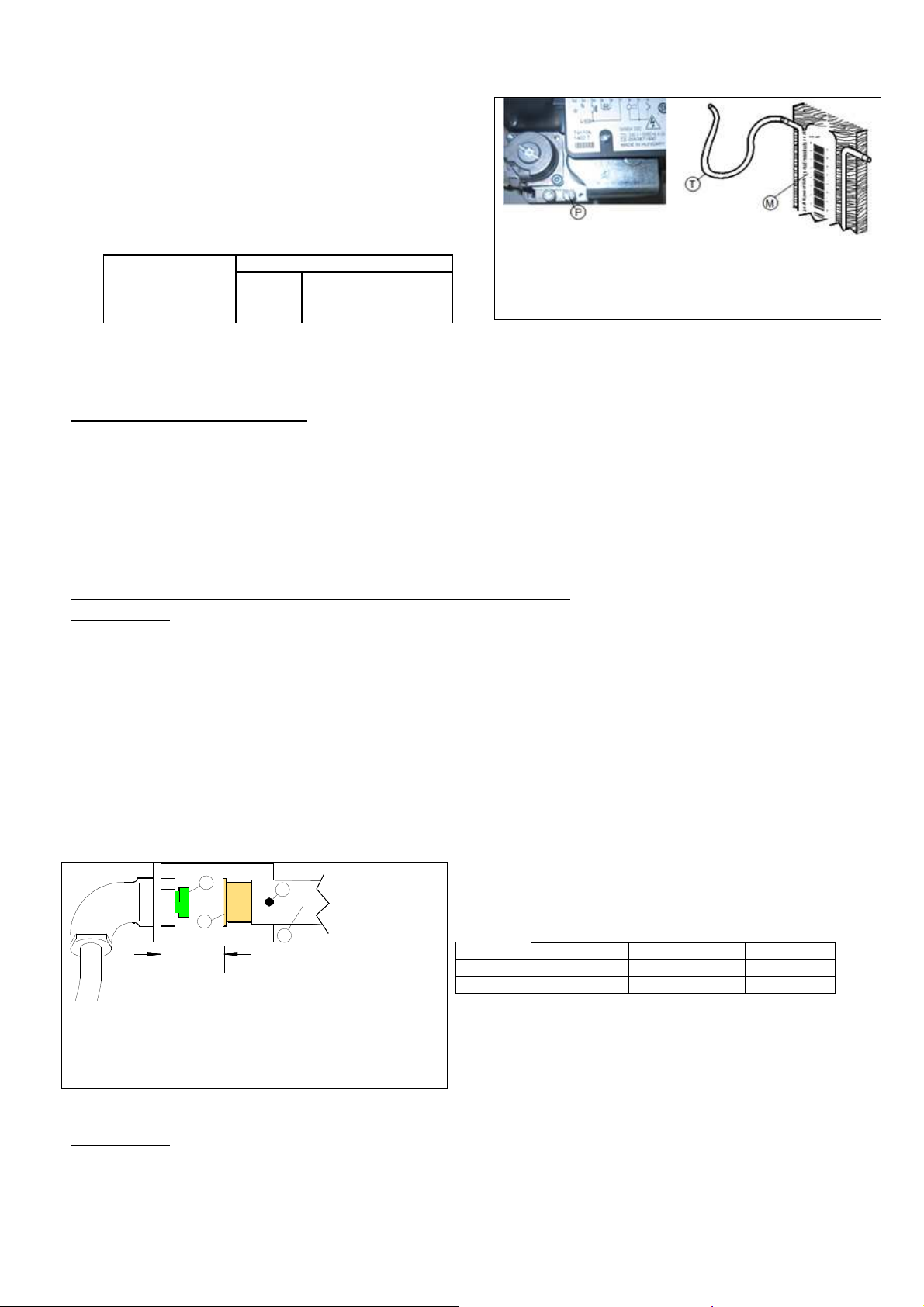
3.2 Check of connection pressure (Fig. 6)
The connection pressure is measured, with the unit working, using a pressure gauge for liquids
(for instance a liquid-level gauge with a minimum resolution of 0,1 mbar). To carry out this test,
remove the back of the unit and connect the “T” hose of the “M” gauge to the “P” inlet
pressure tapping point of the gas solenoid valve, after unscrewing the tapping point screw.
_________________________________________________________________________________________ page. 11
TECNOEKA Srl _____________________________________________________________ use and instruction manual
Measure the conne
ction pressure: if this value is
Fig. 6
not in the range shown in table 2 and it cannot be
brought within these values by adjusting the
pressure reducers of the gas supply system,
definitive start-up of the appliance is quite
impossible.
The gas supply Body must be informed about this
Type of gas
Methane gas H G20 20 17 25
LPG gas G30/G31 28-30 18-20 33-35
Gas pressure (mbar)
Normal Minimum Maximum
Table 2
.
Key:
T = Hose
M = “U” pressure gauge
P = Pressure take-off at entry of gas solenoid-valve
After you have measured the connection pressure, disconnect the hose “T” and screw the
tightness screw of the pressure take-off “P”.
3.3 Adjustment to Other Gas
To adapt the oven to a type of gas that differs from the one tested in the factory (see technical
data plate), replace the injector of the main burner and adjust primary air inflow with the
adjustment bush. For this, disconnect the power and, after removing the lateral left panel,
access the burner and the primary air adjuster. If you do not have the necessary spare parts,
contact the manufacturer’s technical assistance service. Adaptation must be effected by
qualified personnel. Consult the technical specifications in table 1 and 3, and then replace the
main injector and adjust primary air.
3.4 Injector replacement and adjustment of primary air (Fig. 7)
WARNINGS!
Before you attempt this operation, make sure you shut off the gas ON/OFF tap
located upstream of the appliance and disconnect electrical power to the appliance.
After removing the lateral left panel of the unit, carry out the following operations in series:
- Loosen the “V” locking screw with a spanner or a screwdriver and pull out bush “B“
towards the burner Venturi pipe.
- Using a 13 mm wrench, unscrew and replace injector “U” with the appropriate injector
for the new type of gas installed, referring to table 3 and checking if the diameter is
stamped on it.
- Adjust air bush “B” to the correct distance H, which is the distance in millimetres
between the flat seat of the injector-holder and the adjustment bush.
- Seal the screw and bush with paint.
- Refit the back of the unit.
U
B
H
Key:
B = Primary air bush
T = Burner Venturi tube
U = Injector
V = Bush securing screw
WARNINGS!
- Using an indelible adhesive, apply the data referring to the new installation on the
- Run the appropriate tightness tests on the gas circuit.
page. 12 __________________________________________________________________________________________
After every adaptation to a new gas, make sure of the following:
technical data-plate or apply a new data-plate to identify the current state of the gas
regulation.
Fig. 7
V
Table 3
T
Gas Pressure Injector diameter Distance H
G30,G31 28-30 mbar 220 1/100 mm 36 mm
G20 20 mbar 320 1/100 mm 24 mm

Convection gas oven rev. 0___________________________________ MODD. EKF 1111G E UD – EKF 1064G E UD
ATTENTION!:
4. USER INSTRUCTIONS (for the user)
-
The appliance is in tented for professional use and must be utilised by personnel
trained to use it.
-
All ordinary maintenance and repair jobs must be carried out strictly by qualified
personnel.
-
All installation, set-up and maintenance operations must be carried out strictly by
installation technicians authorised by the manufacturer, observing the current
national regulations.
-
We advise you to have the appliance periodically controlled by a specialised
technician in order to keep it perfectly efficient – to this end, you are recommend
to sign a maintenance contract.
4.1 General Information
- When using the oven for the first time, we advise you to run it load-free at maximum
temperature for about one hour. In this way, any unpleasant smells, due to thermal
insulation, and grease residue from assembly are eliminated.
- Make sure that nothing prevents air from flowing into the burner and, in general, into
the ventilation of the room. Do not obstruct the burned gasses outlet or the oven flue,
and do not place any objects over these points.
- Check regularly the efficiency of the extraction unit, the exhaust pipes and the building
flue (no soot for instance).
- Survey the oven while it is in operation
- Shut the gas and water ON/OFF taps upstream and disconnect electrical power when you
have finished using the oven.
- This appliance must be exclusively used for the purposes for which it was expressly
designed, i.e. cooking foods in the oven, any other use is improper.
- The oven can be used for all oven cooking of pastry, bakery and gastronomy products,
fresh and frozen, for re-conditioning refrigerated and deep frozen foods, for steam
cooking meat, fish and vegetables.
- When placing food in the cooking chamber, allow a space of at least 40 mm between
pans to avoid over-obstructing the airflow.
- Do not use pans with edges higher than necessary: the edges act like barriers preventing
circulation of hot air.
- Pre-heat the oven before each time it is used to guarantee the best performance.
- For the cooking to be as even as possible, place the food evenly in each pan, considering
the size of the pieces, layers or the thickness.
- Do not salt the food when it is in the cooking chamber.
- To check the cooking cycle is proceeding correctly use the internal light in the chamber
do not open the door if it is not necessary, to avoid wasting energy and prolonging
cooking times.
- Do not tamper with the devices sealed by the manufacturer; any tampering is forbidden
and dangerous. The misuse of this unit and partial or total failure to follow these
instructions release the manufacturer from all responsibilities for any damage to property
or injury to people.
4.1.1 Residual risks
After a cooking operation, open the door cautiously, to avoid a violent outflow of heat which
could cause burns. While the oven is in operation, pay attention to the hot zones (marked on
the appliance) of its external surfaces.
The bench or support must be able to support the weight of the machine and house it
correctly. The appliance contains electrical parts and must never be washed with a jet of water
or steam. The appliance is electrically connected: before attempting any cleaning operation, cut
power to the appliance. To prevent incorrect connection of the appliance, the relevant electrical,
gas and water connections are marked by identification plates. identification plates.
_________________________________________________________________________________________ page. 13

TECNOEKA Srl _____________________________________________________________ use and instruction manual
1. Tim
e display
2
10
13
14
21
23
24
26
27
4.2 How to use the control panel
4.2.1 Control panel
The keys on the control panel may only be activated with one's fingers, any other object or tool
may cause damage and/or malfunctioning, hence forfeiting the product's warranty
2. Key “+1” to display hours/minutes (on time
display)
3. Key to display current time (on time display)
4. Green LED showing active step
5. Key to select steps
6. Knob
7. Temperature display
8. Set temperature in cooking chamber
9. Actual temperature in cooking chamber
10. Set core probe temperature
11. Actual core probe temperature
1
3
12. Set temperature “
13. Key to select temperatures (shown on
temperature display)
14. Knob
4
15. Blue LED bar to display humidity/steam
16. “Motors at 1/2 speed” key
6
5
17. “STOP motors” key
18. “Preheating” function key
19. Knob
20. “START/STOP” cooking cycle key
7
8
9
21. Program display
22. Key to store programs
23. Key to scroll programs (1÷99)
24. “ON/OFF” key
11
12
25. Key for cooking chamber lighting
26. Key for cooking chamber cooling
27. Key for washing boiler ”(not activable)
to select times
“1”
T”
∆
to select temperatures
“2”
to set humidity/ steam
“3”
15
16
19
page. 14 __________________________________________________________________________________________
17
18
20
22
25

Convection gas oven rev. 0___________________________________ MODD. EKF 1111G E UD – EKF 1064G E UD
5 Switching on
The control panel is automatically activated as soon as the oven is electrically powered.
The
time display
“0000”), the
shows the current time. Press the key to activate the
temperature display
(digits “000”) and the
blue LED bar
time display
(digits
(white LED on). The oven
is ready for setting cooking parameters
6 Operative mode
Programming the cooking time
To set the cooking time (from 1 minute to 4 hours) use knob “1”. Any set value is visible on
the
time display
Programming cooking temperature
To set the cooking temperature (from 50°C to 270°C in cooking chamber and from 0°C to
100°C for “∆T” and for the “core” probe) use knob “2”. Any set value is visible on the
temperature display.
Programming cooking humidity/steam
To set the amount of humidity/steam use knob “3”. The set value is visible on the
formed by
function is disabled (convection operation) .
Warning
The white led blinks whenever the burner of the oven is active.
Selection of cooking step
.
10 blue LEDs
light bar
(from 10 to 100%). The white LED indicates that the humidity/steam
To select the cooking step (from 1 to 4) press the key . The green LED comes on to indicate
the selected step.
The desired cooking parameters may be set for each selected step (times / temperatures
/ humidity / steam).
Press the key and the time of each cooking step may be checked at any moment.
During oven operation (on the time display) it is possible to view the residual cooking time of all
4 steps (the flashing LED indicates the operative step at that moment).
An “infinite” time may be set in the first and fourth step (turn knob “1” anti-clockwise): the
time display reads “
of cooking). In these cases the other steps can no longer be selected.
” (first step) or “
inF
” (fourth step: useful to keep food warm at the end
HoLd
Selecting cooking temperature
To select cooking temperature (in cooking chamber/“core” probe/”∆T”) press the key .
The green LED comes on to indicate the selected temperature.
The values of selected temperatures are visible on the
temperature display
.
Temperature in cooking chamber
When the oven is switched “ON” the temperature is automatically selected in cooking chamber
(LED on ) .
To set the desired value use the knob “2”. During oven operation the display reads alternatively
the set temperature (led on ) and the actual temperature in cooking chamber (led on ).
_________________________________________________________________________________________ page. 15

TECNOEKA Srl _____________________________________________________________ use and instruction manual
Temperature “at the core” of the food
To set the temperature at which you wish to cook the inside of the food, press the key until
the LED of the symbol comes on and use the knob “2”. During oven operation (with the
needle-shaped thermal probe inserted in the food) the display reads alternatively the set
temperature (led on ) and the actual temperature inside the food (led on ).
Temperature ∆T (DELTA-T)
To set the temperature related to function “∆T”, press the key until the LED of the symbol
comes on and use knob “2”.
∆T
During oven operation (with the needle-shaped thermal probe inserted in the food) the display
reads alternatively the actual temperature in cooking chamber (led on ) and the temperature
set for “∆T” (led on
Note:
If the temperature in the cooking chamber is set and then the "core” temperature of the
food, the function “
).
∆T
∆T” is automatically disabled.
If the "core” temperature of the food is set and then the temperature for function “∆T”,
the cooking chamber function is automatically disabled.
Selection of the cooking program number
To select the cooking program number (there are 99 programs) press the key (from 1 to
99) or key (from 99 to 1). The selected program number is visible on the
To scroll programs quickly hold the key.
programs display.
Function “motors at ½ speed”
To activate this function press the key . Activation is confirmed by the green LED coming on.
The function remains operative until the key is pressed again.
If the function is inserted in one of the four cooking steps, it is automatically disabled when
moving to the next cooking step.
The function cannot be activated during a programmed cooking cycle
.
It is useful to bear in mind that by halving the motors speed (fans), the heating power is also
halved hence it is indispensable to adapt cooking times and quantities. (The different noise
produced by motors is wholly normal at reduced speed).
“Stop motors” Function
To activate this function press the key . Activation is confirmed by the green LED coming on.
The function remains operative until the key is pressed again.
If the function is inserted in one of the cooking steps, it is automatically disabled when moving
to the next cooking step
.
The function may be activated and disabled at any time, including during a programmed
cooking cycle
.
It is useful to bear in mind that with motors (fans) blocked the heating elements and climate
adjustment are disabled.
For this reason the function, suitably inserted within a program, may be used as delay to start
the cooking cycle or as pause during the cycle itself (leavening the food inside the cooking
chamber).
page. 16 __________________________________________________________________________________________

Convection gas oven rev. 0___________________________________ MODD. EKF 1111G E UD – EKF 1064G E UD
“Preheating” function
To activate this function press the key . Activation is confirmed by the green LED coming on
The function is automatically disabled when the “preheating” temperature
is reached;
otherwise, it may be disabled by pressing the key even during an operative step (oven
“preheating” may be interrupted at any time).
The function activated in a programmed cooking cycle is not stored with the other program
parameters, that is why it must be activated in real time, every time a new cooking cycle starts:
either programmed or in “manual” mode.
The function adds a temperature ∆ (delta) (+30°C) always and only to the temperature value
already set in the first step of the cooking cycle
, in order to offset the heat loss due to opening
the oven door when the food to be cooked is loaded.
If the step is activated, when the cooking cycle starts the time display reads “HEAt”. As soon as
the set "preheating" is reached, a “beep” goes off, which is only interrupted when the oven
door is opened to load the food (“HEAt” continues flashing).
When the door is subsequently closed, the programmed cooking cycle is automatically started,
and the time display shows again the set cooking time.
Storing programs
Select the number of the program you intend to store. Set in sequence the parameters:
time/temperature and climate for each of the four cooking steps. Press the key until the
“beep” of successful storage.
To delete a stored program just replace it with a new program (having the same number) where
new parameters for the four cooking steps are to be set. The new program must then be
stored.
“START/STOP” key
After selecting a programmed cooking cycle or setting a cycle in “manual” mode, press the key
.
to start cooking. The start of the cooking cycle is confirmed by the green LED coming on
and the “beep”. Press the key again to interrupt cooking at any time.
“Stop gas” Reset
- The “stop gas” words signals the “thermal shutdown” of the oven, i.e. non
ignition of the burner. It appears whenever insufficient gas is delivered to the burner (no flame)
while the oven is being started up or while it is operating.
Warning
When the oven burner is ignited for the first time, as there may be air in the gas pipe supplying
the appliance, the burner “release” operation may have to be repeated several times. In other
words, you may have to press the button several times to allow any air in the pipe to flow
out through the burner and thus obtain correct flow of gas to the burner (flame present).
“ON/OFF” key
Press the key to switch on and off the oven. When the oven is off the green LED is on and
vice versa. When the oven is in the cooking stage the key is disabled:
before switching off the oven
(press the “START/STOP” key).
cooking must be stopped
”LIGHT“ key
Press the key to light the cooking chamber. Activation of the function is confirmed by the
green LED coming on. The light goes out automatically after 60 seconds. If the key is kept
pressed until the confirmation “beep”, the light stays always on; press the key again to switch it
off.
_________________________________________________________________________________________ page. 17

TECNOEKA Srl _____________________________________________________________ use and instruction manual
“Cooking chamber cooling” key
To quickly cool the oven chamber after ending a cooking cycle, hold the door open and press
the key .
Activation of the function is confirmed by the green LED coming on. During forced ventilation,
the temperature display shows the temperature value in the cooking chamber moment by
moment.
Warning
During open door operation do not remove the fan cover; do not touch the moving fans and
resistors which are still hot.
“Clock +1” key
At the end of the cooking cycle a “beep” goes off for 10 seconds and the time display starts
flashing the digits “0000”.
During the flashing (active for 60 seconds) press the key . to lengthen cooking time: each
pressure of the key increases the time by one minute (option disabled at the end of a cooking
cycle with core probe).
With the oven “OFF” the time display shows the current time: to modify it or insert it ( if
missing) use the key .
Insert or modify the current time
With the oven ”OFF”, press the key and the two hour digits start flashing on the time
display.
Insert the current hour with knob “1”
The day of the week is visible on the temperature display (from 1=Monday to 7=Sunday). Insert
the current day with knob “2”
Press the key and the two minute digits start flashing on the time display. Insert the current
minutes with knob “1”
Pressing the key on the time display brings up the entire time.
“START clock” key
With the oven “ON” or during the cooking cycle, press the key to check the current time
on the time display at any time (the other displays are disabled).
Programmed switching on
With the oven ”OFF” press the key to view the parameters already inserted for
programmed switching on: the time (time display), the day (temperature display) and the
number of the cooking program (program display).
To modify them press the key .
The time display starts flashing the two hour digits: insert the desired switch on hour with the
knob “1”.
The temperature display starts flashing the day digit: insert the desired day with the knob “2”
(from 1=Monday to 7=Sunday).
The program display starts flashing the two program number digits: insert the desired cooking
program number with the scrolling buttons.
Press the key again and the time display starts flashing the two minute digits: insert the
desired minutes with knob “1”.
Press the key
and the time display shows the current time. Press the key : the green
LED starts flashing to confirm that the oven is ready (stand-by) for programmed switch on.
page. 18 __________________________________________________________________________________________

Convection gas oven rev. 0___________________________________ MODD. EKF 1111G E UD – EKF 1064G E UD
Press the key again to cancel the programmed switch on.
Cooking in “manual” mode
After switching on the oven (in “ON” / green LED off) set the value of each parameter required
for cooking.
Set the cooking time (visible on the time display) with knob “1”:
-
-
“inF” (steps excluded / step LED off)
from one minute to 4 hours per step (“inF” excluded / step LED on)
Set the cooking temperature (visible on the temperature display) for one or more steps, with knob “2”:
-
-
- ∆
Set the amount of humidity/steam (optional parameter) for one or more steps, with knob “3” (blue LEDs on from
10 to 100%)
cooking chamber from 50°C to 270°C (LED on )
core probe (optional parameter) from 0°C to 100°C (key
T / DELTA-T (optional parameter) from 0°C to 100°C (key
/LED on )
/ (LED on
“∆T”
)
Set the “preheating” function (optional parameter) pressing the key .
Set the “motors at ½ speed”function (optional parameter) for one or more steps pressing the
key . Start the cooking cycle by pressing the key .
Please note
If the cooking cycle is not controlled by the core probe and has been divided into one or more timed steps, the
oven automatically switches off when the time set in the individual step or overall in the various steps has elapsed.
If an “inF” (“infinite”) cooking time has been set the oven continues working until the operator switches it off by
pressing the key .
If the cooking cycle is controlled by the core probe and has been divided into one or more steps (even timed),
when the temperature set with the probe is reached it moves to the next step; if on the other hand one step only
has been opted for (even timed), or an “inF” time, the cycle ends and the oven switches off automatically,
regardless of the time set for the step.
Cooking in “programmed” mode
If cooking programs have already been stored - the program number matches a specific cooking
cycle for a specific food - using them is easy.
After switching on the oven (“ON”/green LED off) select the number of the stored program
(visible on the program display) using the key or .
Start the cooking cycle by pressing the key .
At the end of the cooking cycle the oven switches off automatically and a “beep” goes off for
10”.
Please note
Before starting the cooking cycle it is possible to check the value of the parameters set on the four
steps (press the key
operative they must be stored (press the key
) and modify them if necessary. For the modified parameters to become
until the confirming “beep”).
When the cooking cycle has started it is no longer possible to modify the value of stored parameters.
_________________________________________________________________________________________ page. 19

TECNOEKA Srl _____________________________________________________________ use and instruction manual
7. Cooking types
Convection cooking
Set in sequence the
knob “2”) for each of the steps provided (key ). Start the cooking cycle by pressing the key
.
Convection cooking + humidity/steam
Set in sequence the
knob “2”) and the
the steps provided (key ). Start the cooking cycle by pressing the key .
Cooking with “core temperature” function
Set in sequence the
“time”
“time”
parameter (turn knob “1”) and the
parameter (turn knob “1”), the
“humidity/steam”
“time”
parameter (turn knob “1”), the
“temperature”
“temperature”
parameter (turn
parameter (turn
parameter (turn knob “3”/blue LED bar active) for each of
“temperature”
parameter (turn
knob “2”), the
“core temperature”
the intended step (key ) and, if desired, the
parameter (key /green LED on /turn knob “2”) for
“humidity/steam”
parameter (turn knob
“3”/blue LED bar active) for each of the intended steps (key ). Start the cooking cycle by
pressing the key .
The temperature inside the food to be cooked (core) may be set, using the suitable needleshaped thermal probe (core probe) supplied.
The probe must be inserted inside the food, in the thickest area, avoiding contact with any
bones. After placing the food in the cooking chamber, extract the cable of the thermal probe
and close the oven door. The plug of the probe must be connected into the suitable socket
located at the bottom of the control panel.
When starting a cooking cycle where the core probe has been enabled in one of the steps (the
time display reads: “Prob”), when the set temperature is reached in the food, the cooking cycle
moves to the next step regardless of the set time.
If however, the core probe is enabled in any of the four steps, leaving the other three disabled,
the cooking cycle ends automatically when the temperature set inside the food is reached,
regardless of the set time. Since the needle-shaped thermal probe is an extractable accessory or
liable to be broken, it is a good rule to set the cooking time also in the step using it.
If the probe is connected and working, the step ends when the set temperature is reached;
otherwise (probe not connected or broken), the step uses the set time.
In any case failed connection (or breakage) of the probe is signalled upon
starting the cooking cycle: an acoustic alarm goes off (intermittent “beep”) for 10 seconds,
“Prob” starts flashing on the time display, while the
value previously set ( - - - ) disappears from the temperature display.
The "core" temperature of the food may even just be detected (no value set): it is sufficient for
the needle-shaped thermal probe to be inserted in the food.
In this case (with cooking cycle started), by pressing the key the temperature detected by
the probe is automatically selected (visible on the temperature display) (LED on ).
Warnings
Before removing the food from the oven after cooking with the needle shaped thermal probe
(core probe), carefully extract the still hot probe from the hot food, paying attention not to
let it hang outside the cooking chamber: it may cause burns. Before any immediate reuse it is
recommended to cool it (thus also preventing harmfully piercing the food).
damage the needle shaped thermal probe (core probe), avoid using it in high temperature cooking
(OVER 230°C); also avoid letting the probe cable come into contact with the hot metal surfaces inside
the cooking chamber.
page. 20 __________________________________________________________________________________________
In order not to irreparably

Convection gas oven rev. 0___________________________________ MODD. EKF 1111G E UD – EKF 1064G E UD
Cooking with function “∆T” (DELTA-T)
Set in sequence the
“time”
parameter (turn knob “1”), the
“core temperature”
parameter
(key /green LED on
(key /green LED on
turn knob “2”) for the intended step (key ), parameter
/
/turn knob “2”) and, if desired, the
“∆T”
“humidity/steam”
“∆T”
(parameter
(turn knob “3”/blue LED bar active) for each of the intended steps (key ). Start the
cooking cycle by pressing the key .
This function makes it possible to maintain constant, throughout the cooking step, the
difference (∆T) between the temperature inside the food (temperature detected by the needle-
shaped thermal probe) and the temperature inside the cooking chamber. This means that the
value of the temperature in the cooking chamber becomes the sum of the temperature inside
the food and a fixed temperature value “∆T” set by the user (see graph).
Cooking chamber (°C)
200
150
100
50
Temperature in
cooking chamber
Temperature
inside food
Delta T temperature
∆
0
Cooking time (min.)
The Delta-T temperature is obtained from the
difference between the values of the temperature
inside the food and the temperature in cooking
chamber
In practical terms, there is a slow increase of the temperature in cooking chamber, with a
constant difference with respect to the internal food temperature which, exactly because of
that, undergoes a prolonged and delicate cooking process (in the case of meat, proteins are
protected since surface tensions caused by excessively quick crust formation are avoided).
After selecting the cooking temperature for the inside of the food (“core” temperature) and
setting the value (knob “2”), press key again, in order to select function “∆T” (the
∆T
LED
switches on) and be able to set (knob “2”) the desired temperature value (experience suggests
this value should be between 30°C and 70°C).
Also for cooking with function “∆T”, the method to use the needle-shaped thermal probe is as
described in paragraph “cooking with “core temperature” function.
Please note
If the cooking cycle is not controlled by the core probe and has been divided into one or more timed steps, the
oven automatically switches off when the time set in the individual step or overall in the various steps has elapsed.
If an “inF” (“infinite”) cooking time has been set the oven continues working until the operator switches it off by
pressing the key .If the cooking cycle is controlled by the core probe and has been divided into one or more
steps (even timed), when the temperature set with the probe is reached it moves to the next step; if on the other
hand one step only has been opted for (even timed), or an “inF” time, the cycle ends and the oven switches off
automatically, regardless of the time set for the step.
_________________________________________________________________________________________ page. 21

TECNOEKA Srl _____________________________________________________________ use and instruction manual
8 Door device
The device interrupts oven operation (interrupting the cooking cycle) every time the door is
opened; when the door is closed the cooking cycle resumes from where it was interrupted.
9 Black-out
When power supply is restored after a black-out, the oven starts working again by pressing key
(the set cooking cycle parameters remain stored).
10 Communicating with the PC
In the lower portion of the control panel (side view) there is a serial port for interactive PC
communication. (Remove the suitable protection to access the serial port).
By connecting a PC with the “wineka software” (optional) to this port, it is possible to transmit
to the oven's “memory” up to 99 cooking programs (recipes) already pre-set (customised) in all
operative parameters; conversely, it is possible to acquire from the oven's “memory” the
existing cooking programs (recipes) already activated.
11. Cleaning
11.1 General cleaning
Before performing any cleaning on the appliance, disconnect the power supply (act on the
safety magnetic circuit breaker) and water supply (close the water cock). Let it cool completely.
The appliance must be cleaned at regular intervals, even daily, to assure best functionality and
lengthening its life cycle.
The appliance also has electrical components inside, for safety reasons
with water or steam jets especially if aimed at the vents on the metal surfaces of its outer casing
(possible hazardous seepage detrimental to electrical components).
In the event specific detergents (degreasers) are used for cleaning stainless steel, ensure they do
not contain corrosive acid substances (no presence of chlorine even if diluted) or abrasive
substances. Carefully follow the instructions and warnings of the detergent's manufacturer and
take precautions such as using adequate rubber gloves.
Strictly avoid using scouring pads, steel wool and scrapers that may ruin the treated surfaces.
Also avoid prolonged permanence on the steel surfaces of foods containing acidic substances
(lemon juice, vinegar, salt, etc.) which cause corrosive deterioration.
11.2 Cleaning the cooking chamber
Manual cleaning
For hygienic reasons it is good practice to clean the cooking chamber on a daily basis, at the
end of every day the oven is used. Correct cleaning also prevents the formation of corrosive
phenomena inside the chamber, as well as preventing the danger of accidental combustion due
to any grease and food residues accumulated over time.
To aid cleaning remove the side grilles.
The cleaning detergents must not contain abrasive substances or substances of acid/corrosive
nature.
In case of lack of appropriate detergents it is sufficient to clean the cooking chamber with a
sponge soaked in warm soapy water or warm water and a little vinegar..
Rinse with plenty of water (use the suitable shower head if available) and dry well with a soft
cloth.
The side grilles must be cleaned separately and fitted back on.
When cleaning is completed leave the oven door slightly open.
it is forbidden to wash it
page. 22 __________________________________________________________________________________________

Convection gas oven rev. 0___________________________________ MODD. EKF 1111G E UD – EKF 1064G E UD
Semi-automatic cleaning
(ovens fitted with automatic humidification/steam generator)
- spray specific degreaser for stainless steel on the internal walls of the cooking chamber,
on the side grilles, on the fan covers (do not spray onto the fans through the grille) and
on the internal door glass;
- let the product act for about 20 minutes with closed door;
- switch the oven on adjusting the temperature at 70-80°C;
- run a cycle with maximum steam (100%) for about 15 minutes;
- upon completing the cycle switch off the oven, let the cooking chamber cool and rinse it
with plenty of water (use the suitable shower head if available)
- dry by running a heating cycle adjusting the temperature at 150-160°C for about 10
minutes (repeat the cycle if necessary).
When cleaning is completed leave the oven door slightly open.
Automatic cleaning (set-up ovens)
If already installed, the “KWT” washing system allows the oven's cooking chamber
to be automatically cleaned.
The “KWT” washing system offers the following programs:
1. L1 – Short washing
2. L2 – Medium washing
3. L3 – Long washing
4. P – Pre-loading detergent and rinse aid from the peristaltic pumps
5. R – Rinse and dry the cooking chamber without using any chemicals.
The (optional) “KWT” kit is ready to be installed also at a later stage in oven models supporting
it.
Important
It is recommended to use the program “P” when first using the “KWT” washing system. In this
way the air inside peristaltic pumps and detergent and rinse aid tubes is removed, thus assuring
correct functionality of the system.
When cleaning is completed leave the oven door slightly open.
Warnings
Do not open the door during washing operations, as chemical substances used for cleaning and
hot fumes might escape.
Danger of corrosion and burns!
When the cooking chamber temperature exceeds 100°C (time display reads “Hot”) washing
cannot be activated.
Before starting a cooking cycle ensure there are no detergent residues in the chamber that has
just been washed. Any residues must be removed with a moist cloth suitably protecting your
hands, eyes and mouth, and the cooking chamber must be thoroughly rinsed.
11.3 Cleaning the door seal
For hygiene and good operations, it is good practice to clean the door seal at the end of each
day’s work. It should be carefully washed with warm soapy water, rinsed and dried with a soft
cloth. Any incrustations or food deposits must be carefully removed, without using sharp metal
tools which could irreparably damage the seal.
11.4 Cleaning the door
The glass on the door inside the cooking chamber can be cleaned with the same degreaser as
used for cleaning the chamber or a normal glass cleaning product can be used (non toxic).
Normal glass cleaning products can also be used to clean the glass on the outside of the door,
or simply warm soapy water, rinse and then dry the glass well with a soft cloth.
If dull marks form between the two door glasses, these can be removed by opening the internal
glass. To do this, with open door, move the " grip " available on the right side of the top (
metal ) section that holds the internal glass, and pull up to release the glass from its " clips"
seats.
After clearing the dirt between the two glasses , close the internal glass pushing the outer glass
until it hooks back to its " clips" seats.
_________________________________________________________________________________________ page. 23

TECNOEKA Srl _____________________________________________________________ use and instruction manual
11.5 Cleaning the external casing
The outer steel surfaces must be cleaned with a cloth soaked in warm soapy water or mixed
with a little vinegar, they must be rinsed well and dried with a soft cloth.
Should you wish to use specific products on the market, these must comply with the cleaning
requirements set out in the “General information” paragraph”.
It is worth remembering that the counter supporting the appliance or the floor surrounding the
area where the appliance is should also be cleaned without using acid corrosive substances (e.g.
muriatic acid) since the vapours released by them might corrode and deteriorate the outer steel
shell and cause irreparable damage to the electrical components inside the appliance.
11.6 Inactivity period
Should the appliance not be used for a long extent of time, it is good practice to disconnect it
from the power supply (act on the safety magnetic circuit breaker located upstream of the
appliance), the gas supply (close the stopcock on the mains) and water supply (close the
stopcock on the mains). It is recommended to clean it with care internally (cooking chamber)
and externally, paying special attention to removing any salt residues which might lead to
corrosion on the steel surfaces. It is also recommended to protect the appliance with oil-based
spray products (e.g. Vaseline oil) which form an effective protective film when sprayed on the
surfaces. Leave the door of the cooking chamber ajar.
Adequately covering the appliance, finally, allows it to be protected from dust.
12. Maintenance
12.1 General information
A periodic check (at least once a year) of the appliance contributes to extending its life and
assures proper functionality.
Any maintenance operation on the appliance must only be done by highly qualified personnel
trained in the operations to be performed. Before performing any maintenance on the
appliance, the power supply must be disconnected (act on the safety magnetic circuit breaker
located upstream of the appliance) and let it cool down. The components that might require
maintenance are accessible by removing the left side and/or back of the appliance.
12.2 Lamp on door
Electrically disconnect the appliance. The lamp is housed between the two door glass panes.
Just open the inside glass pane to replace it. Replace the lamp with one having the same
functional features. The lamp is of the halogen type: it must not be touched with bare hands.
Close the internal glass again and connect to the power supply.
12.3 Door gasket replacement
The door gasket has a rigid profile with retainer fins. This profile must be inserted in the suitable
guide on the front of the cooking chamber. To replace the gasket just remove the worn one
from the guide (pull harder at the 4 corners). Clean the guide from any dirt and insert the new
gasket (it is advisable to moisten the gasket profile with soapy water to make fitting easier).
12.4 Cleaning the fans
The fans must be regularly cleaned with appropriate descaling products. All their parts must be
thoroughly cleaned, eliminating any limescale. The fan cover must be removed to access fans.
When cleaning is completed fit the cover back on operating in reverse order.
Important
During the assembly of the fan-cover, pay attention to re-position properly, on its locations, the
2 pipes that introduce water to fans; in a different way, the pipes interfere with fans themselves
during the functioning, causing damages to the appliance, of which The Manufacturer cannot
be held responsible
12.5 Resetting the thermal breaker safety device
This device is accessed by removing the left side and/or back of the appliance. The device is
reset by pressing hard the relevant button.
page. 24 __________________________________________________________________________________________

Convection gas oven rev. 0___________________________________ MODD. EKF 1111G E UD – EKF 1064G E UD
Type of fault
Cause of the fault
Corrective action
Non conforming connection to the power mains.
Check connection to the mains.
M
ains voltage not present.
Restore power supply voltage.
Safety thermal device triggered
Contact a skilled technician.
Electronic board protection fuse (control panel)
Excessive over
-
temperature on motor winding.
Cooking cycle set and
/steam in cooking
water flows out of the inlet
Non conforming water mains connection
Check connection to water mains or
Closed stopcock (solenoid valve)
Check the cock.
Obstructed water inlet filter
Clean the filter.
Damaged water inlet solenoid valve or pump
Contact a skilled technician.
Closed door: /water/steam
Non conforming gasket assembl
y. Check gasket assembly.
Damaged gasket
Contact a skilled technician.
Loosened handle mechanism (side opening door)
Contact a skilled technician.
One of the motors is locked or turns at low speed
Contact a skilled techn
ician.
The motor does not reverse direction.
Contact a skilled technician.
Resistor not powered or damaged
Contact a skilled technician.
Damaged lamp.
Replace the lamp.
Lamp not correctly tightened
Ensure t
he lamp is correctly tightened.
Damaged lamp power supply unit
Contact a skilled technician
Core probe
-
electronic board
Check connection to the electronic
The temperature display reads
“Er3”
and
The temperature display flashes
“Hot”
Forced aeration vents on the oven
Non conforming water mains
Water level probe damaged by
13 Possible faults
The oven does not work
activated: the oven does
not work.
Production of
humidity
chamber activated: no
pipes
escapes through the
gasket.
The oven does not cook
evenly.
Lamp in the cooking
chamber does not work.
14 Possible alarms
blown.
Heat sources too close to the oven.
Door open or ajar.
Damaged door micro-switch/sensor.
Non conforming pump connection.
Tank without water (pump)
Contact a skilled technician.
Contact a skilled technician.
Close the door properly.
Contact a skilled technician.
pump connection.
Check for water in the tank.
Type of alarm Cause of the alarm Corrective action
The temperature display reads
The temperature display reads
a buzzer goes off which may be silenced
by pressing key .
Although cooking may continue, the
cause of the fault causing the oven's
electronic board to overheat must be
eliminated
The operating oven automatically
switches off and a buzzer goes off for
30 seconds.
The oven may only be restarted when
the electronic board has cooled down
completely
Intermittent buzzer alarm from steam
generator control unit (no water in the
steam generator).
“Er1”
“- - - “
Cooking chamber probe-electronic
board connection interrupted
Damaged cooking chamber probe Contact a skilled technician
connection interrupted
Damaged needle-shaped core probe Contact a skilled technician
Damaged cooling motorfan Contact a skilled technician
Forced aeration vents on the oven
casing obstructed
Heat sources too close to the oven Eliminate heat sources
Damaged cooling motorfan Contact a skilled technician
casing obstructed
Excessive heat sources too close to
the oven
connection
Closed stopcock Check the cock
Obstructed water inlet filter Clean the filter
Damaged water inlet solenoid valve Contact a skilled technician
Check connection to the electronic
board
board
Free the obstructed vents
Free the obstructed vents
Eliminate heat sources
Check connection to the water mains
_________________________________________________________________________________________ page. 25
limescale
Contact a skilled technician

TECNOEKA Srl _____________________________________________________________ use and instruction manual
15 Wiring layout
M Power supply terminal board
T1 Safety thermostat
MI Door microswitch
Filtro Anti-noise filter
E Water solenoid-valve
F Fuse
SMI Microprocessor card
CE Gas control card
SG Gas card
SL Washing card
Key
V1-V2 Radial motorised ventilator
V3 Tangential motorized ventilator
C1-C2 Capacitors
E1 Ignition electrode
E2 Detection electrode
S1 Cooking chamber probe
S2 Food core probe
T 230/12V transformer
L Lighting lamp
page. 26 __________________________________________________________________________________________

Convection gas oven rev. 0___________________________________ MODD. EKF 1111G E UD – EKF 1064G E UD
COMPONENTE
CODICE TECNOEKA
Oven burner
012036
10
Ignition/ detection plug
012
03620
Power cable
00002370
Gas control unit
01900031
Microprocessor card
01900050
Gas card
01900060
Washing card
01900480
Door microswitch
00010510
Capacitor
01201030
Water solenoid
-
valve
01201860
Gas solenoid
-
valve
01201810
Anti-noise filter
0
1202010
Power supply terminal board
01200720
Oven ventilation motor
01202600
Oven cooling motor
01202330
Lamp holder
00005690
Safety thermostat
01202780
T
ransformer
00012590
Fuse holder
00005840
Fuse 2A
01201820
The separate collection of the rubbish and subsequent treatment, recovery and disposal help to
16. TECHNICAL ASSISTANCE AND ORIGINAL SPARE PARTS
Before leaving the factory, this appliance was tested and set up by expert, specialised personnel,
to ensure best operating results. Any eventual assistance or regulation must be done with
maximal care and attention, using original spare parts.
For this reason it is necessary to apply to the distributor that has done the sale, specifying the
type of inconvenience and model of the appliance purchased. The required parts for different
gas type adaptation are available along with the appliance at the moment of sale or delivery.
For any maintenance the user can contact Tecnoeka by calling the telephone numbers on the
cover or going to
www.tecnoeka.com
16.1 Spare parts list
.
17. Informations to the consumers
Further to Directive 2002/96/EC, the symbol of the crossed rubbish skip on
the appliance means that at the end of its life, the product must be
disposed of separately from the other rubbish. The user must hand the
appliance to a specialised waste collection centre for electric and electronic
equipment.
produce other equipment using recycled materials, reducing the negative effects on the
environment and public health, which would be caused by incorrect management of the
rubbish.
Should the user dispose of the product abusively, administrative sanctions would be applied.
_________________________________________________________________________________________ page. 27

TECNOEKA Srl _____________________________________________________________ use and instruction manual
18. The Warranty
Your appliance is covered by warranty. The seller will replace or repair (and his decision will be final), free
of charge for the customer, only those parts that are defective due to a manufacturing fault on condition
that, under penalty of forfeiture:
− for domestic equipment, the customer notifies the fault within two months from the date when
he/she discovered it and anyway within 2 years form the date of purchase;
− for professional equipment, the customer notifies the fault within 8 days from the date when
he/she discovered it and anyway within 12 months from the date of purchase,
enclosing a copy of the invoice or receipt proving the purchase.
Apart from the case when the customer cannot produce the invoice or receipt proving the purchase or
when the above-mentioned terms are not complied with, the
warranty is expressly excluded
in the
following cases:
1) faults or breakage caused by the transport;
2) wrong or incorrect installation of the product (for instance because of insufficient draught of the
flue or exhausts) in light of the instructions given in the user’s handbook supplied with the
product;
3) inadequate or abnormal electrical, hydraulic and/or gas supplies;
4) carelessness, negligence or incompetence in using the product in light of the instructions given in
the user’s handbook supplied with the product;
5) use of the product for uses different from the one for which it was built or anyway in a manner
not compliant with the instructions given in the user’s handbook supplied with the product;
6) tampering with the product;
7) adjustments and/or maintenance and/or repairs carried out by unauthorised personnel and/or
with non original spare parts;
8) inadequate or careless maintenance of the product in contrast with the user’s handbook supplied
with the product;
9) damages caused by fire, natural disasters and accident as well as by any cause not attributable to
TECNOEKA SRL.
In addition painted or enamelled parts, knobs, handles, mobile or removal plastic parts, light globes,
glass parts, refractory stones, electronic parts and any accessory parts and transport from the consumers,
final user and/or purchases location to Tecnoeka srl and vice versa are excluded from the warranty.
Replacement costs of the oven and relative installation expenses are also excluded from the warranty.
TECNOEKA SRL cannot be held responsible for any damages, either direct or indirect, caused by the
product breaking down or following its non-use.
Any repairs carried out during the warranty do not cause said warranty to be extended or renewed.
Nobody is authorised to modify the terms and conditions of the warranty or to issue new verbal or
written warranties. Any dispute shall be settled by the competent Court in Padua.
Warning for the Buyer:
1. the cooking appliance is designed only for cooking purposes while the heating appliance is
designed only for heating domestic environments;
2. TECNOEKA S.r.l. does not install the appliances; the seller shall be responsible for any installation
carried out;
3. TECNOEKA S.r.l. cannot be held responsible for any damages, either direct or indirect, to people,
pets or property caused by the appliance breaking down or following its non-use.
The Manufacturer cannot be held responsible for any inaccuracies due to misprints or mistakes in
copying in this handbook. The Manufacturer reserves the right to modify the products as he deems fit,
also in the interest of the user, without affecting the vital characteristics of functionality and safety.
19 Availability and supply of spare parts
TECNOEKA SRL keeps and ensures the availability of spare parts for a maximum of 24 months
from the date of the sales invoice of the finished product to the dealer. Availability cannot be
guaranteed after said period.
page. 28 __________________________________________________________________________________________
 Loading...