

Page 1
WELDING CONTROL UNIT
INSTRUCTION MANUAL
TE700
FROM SOFTWARE RELEASE N° 1.13
TECNA
via Grieco 25/27 - 40024 Castel S. Pietro Terme – Bologna ITALY
Tel. +390516954411 – Fax +390516954490 – http://www.tecna.net
DOCUMENT
NUMBER:
EDITION: APRIL 2010
®
S.p.A.
MAN 4147
DISTRIBUTOR:
Page 2

Instruction Manual ITEM TE700 TECNA S.p.A.
This page is intentionally left blank.
2/128
Page 3

TECNA S.p.A. ITEM TE700 Instruction Manual
TABLE OF CONTENTS
CHAPTER 1 - TE700 WELDING CONTROL UNIT DESCRIPTION Pag. 6
1.1 - MAIN TECHNICAL FEATURES Pag. 7
1.2 - PANEL CONTROLS Pag. 8
1.3 - PANEL LEDs Pag. 9
1.4 - DESCRIPTION OF DISPLAYED INFORMATION Pag. 10
1.5 - CONTROL UNIT SWITCH-ON Pag. 18
CHAPTER 2 - CONTROL UNIT PROGRAMMING Pag. 20
2.1 - PROGRAM DATA Pag. 21
2.2 - CONSTANT CURRENT OPERATING MODE Pag. 23
2.3 - FIX OPERATING MODE Pag. 27
2.4 - CONSTANT SECONDARY VOLTAGE OPERATING MODE Pag. 31
2.5 - CONSTANT POWER OPERATING MODE Pag. 34
2.6 - CONSTANT ENERGY OPERATING MODE Pag. 37
2.7 - DYINAMIC COMPENSATION OPERATING MODE Pag. 41
2.8 - WORKING PROGRAM PARAMETERS DESCRIPTION Pag. 44
2.9 - SETUP MENU Pag. 54
2.10 - STEPPER MENU Pag. 57
2.11 - ADJUSTMENT STEPPER FUNCTION Pag. 61
2.12 - FEATURES TE700 Pag. 66
2.13 - FEATURES INVERTER Pag. 70
2.14 - PROGRAMS COPY Pag. 75
2.15 - CHECK INPUT – DIAGNOSTIC TE700 Pag. 77
2.16 - CHECK INPUT – DIAGNOSTIC INVERTER Pag. 78
2.17 - PROG. SEQUENCE Pag. 79
2.18 - THICKNESS SENSE Pag. 82
2.19 - TIP-DRESSING Pag. 86
CHAPTER 3 - SEAM WELD OPERATING MODE Pag. 91
CHAPTER 4 - CASCADE OPERATING MODE Pag. 97
CHAPTER 5 - THE WORK CYCLE Pag. 98
CHAPTER 6 - STOP BAD SPOTS Pag. 99
3/128
Page 4

Instruction Manual ITEM TE700 TECNA S.p.A.
CHAPTER 7 - WELDS COUNTER FUNCTION Pag. 105
CHAPTER 8 - ESCRIPTION OF THE INTERFACE OUTPUTS Pag. 107
8.1 - WELD ERROR (WRONG) Pag. 107
8.2 - END CYCLE Pag. 108
8.3 - LOCK Pag. 108
CHAPTER 9 - SELECTING THE WORK PROGRAM THROUGH EXTERNAL
RECALLS
CHAPTER 10 - DOUBLE STROKE FUNCTION Pag. 113
CHAPTER 11 – OPTIONS Pag. 114
11.1 - RS-232 SERIAL INTERFACE Pag. 114
11.2 - INTERFACE FOR PROPORTIONAL VALVE Pag. 116
CHAPTER 12 - DESCRIPTION OF THE SIGNALS ON THE TERMINAL
BOARD
CHAPTER 13 - LIST OF TE700 MESSAGES Pag. 120
13.1 - SYSTEM ERRORS – TE700 Pag. 120
13.2 - SYSTEM ERRORS - INVERTER Pag. 121
13.3 - WORK ERRORS
Pag. 124
Pag. 109
Pag. 117
CHAPTER 14 – TECHNICAL SPECIFICATIONS Pag. 126
4/128
Page 5

TECNA S.p.A. ITEM TE700 Instruction Manual
This page intentionally left blank.
The information contained in this document is subject to modification without prior notice.
No part of this document can be either reproduced or transferred in whatever format neither by electronic nor
mechanic means for whatever purpose, without TECNA’s written permission. TECNA is a registered brand.
5/128
by
Page 6
Instruction Manual ITEM TE700 TECNA S.p.A.
CHAPTER 1 – TE700 WELDING CONTROL UNIT DESCRIPTION
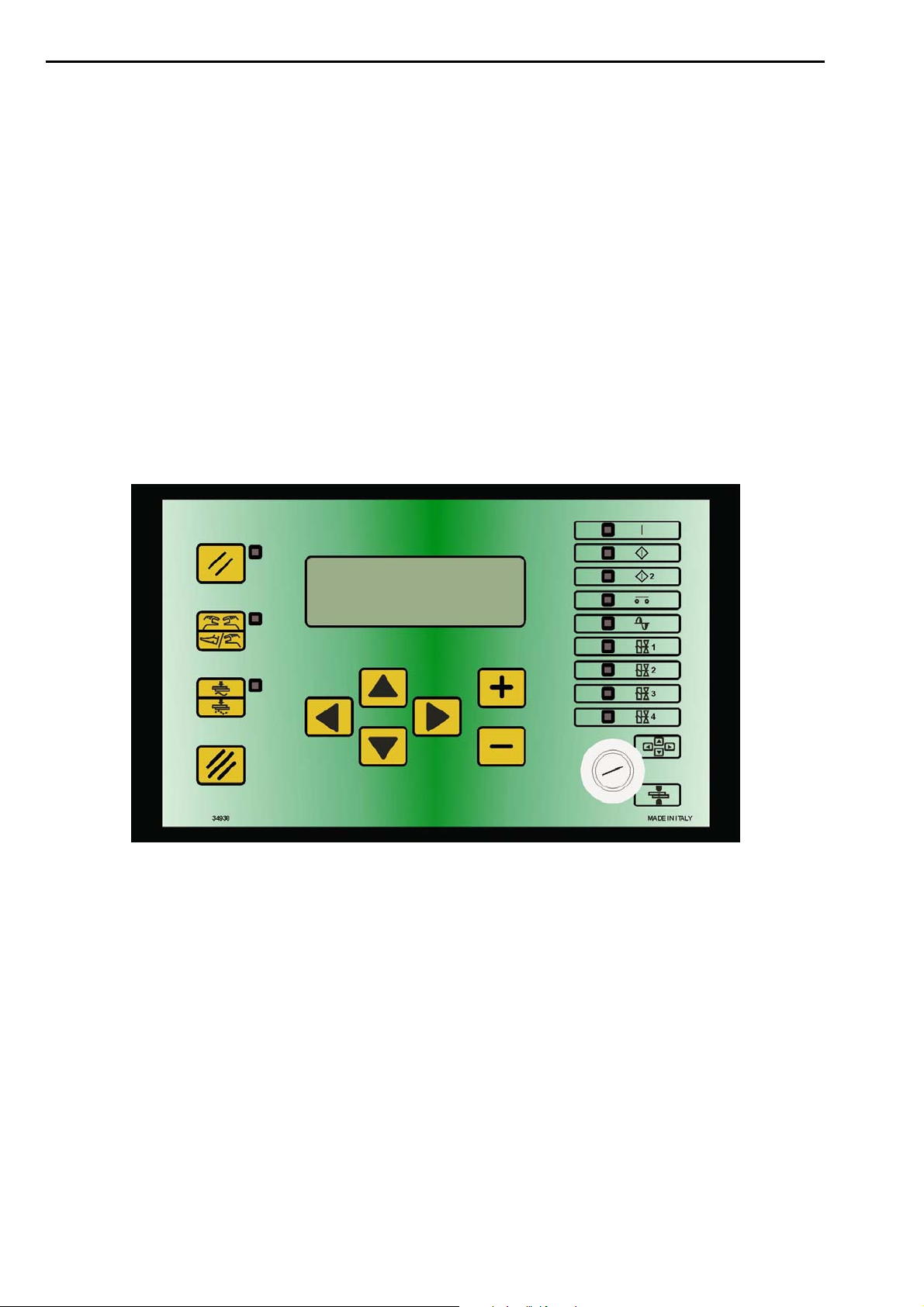
The TE700 is a microprocessor-based welding control unit for resistance welders equipped
with inverter technology. The task of the welding control unit is to manage the components of
the welder, specifically the IGBT power unit that adjusts the welding current.
The TE700 is a particularly versatile control unit since it can be adapted to different types of
welders. In addition to the spot and projection welders, it may also be installed on seam
welders and work with constant current, FIX, constant power, constant voltage, constant
energy adjustment and in dynamic mode. The number of the inputs and outputs may be
increased to better adapt the welding control unit to automatic machines.
The control unit can manage up to max 4 different welding transformers.
It is possible to store up to 300 different welding programs, 255 of which are recalled directly
from an external device. An alphanumeric identifier may be associated with each program to
simplify its identification. Each program comprises several programmable parameters that
describe the work cycle. In addition to the plain 4-stage welding cycle, the control unit allows
the running of welding processes with pre-welding current, post-welding current, slope and
pulses.
6/128
Page 7

TECNA S.p.A. ITEM TE700 Instruction Manual
1.1 – MAIN TECHNICAL FEATURES
Simplified programming via 6 keys and a backlit alphanumeric LCD.
Inverter command with medium frequency IGBT, with possibility of choosing the operating
frequency of the inverter between 1000 Hz and 4000 Hz.
Storage of up to 300 welding programs; 255 may be called from external devices.
Possibility of associating an 8-character alphanumeric identifier with each weld program.
Possibility of managing as many as 4 different welding transformers or one transformer and 4
different types of electrodes.
Overheating protection for the welding transformers.
Up to 32 programmable parameters for each program.
Slope up, Slope down, pulses, pre-weld, post-weld functions and adjustment of the welding times
with units of 1 mS.
Display of the RMS of the welding current, energy, power, RMS of voltage to the electrodes, of the
initial and final resistance, of the machine's thermal use percentage, of the machine's use
percentage and, as an option, of the initial thickness of the welded material and the indentation at
the end of the weld.
6 WORKING MODEs: conventional, constant current, constant power, constant voltage, FIX,
constant energy, DYNAMIC mode.
Limit indicators for: Current, voltage at the electrodes, energy, power, inverter use percentage,
initial and final resistance of the material to be welded; thickness and indentation limit of the
material (optional).
Double stroke function.
Stepper function to compensate the wear and tear of the electrodes with programmable curves and
possibility of intervening independently on the time and the welding current through differentiated
stepper laws. Possibility of using 4 different stepper options associated with 4 different spot
counters associated with each weld program.
Single and automatic cycle. WELD and NO-WELD function.
Control of 5 solenoid valves 24 VDC max. 5 W with self-protected output.
Self-adjustment to the mains frequency 50/60 Hz.
Serial communication with insulated RS232 as an option.
Output for proportional solenoid valve.
Key for selecting foot control or two-hand control.
Selectable languages: Italian, English, French, German, Spanish, Hungarian, Swedish or
Portuguese.
Possibility of upgrading control unit Firmware via appropriate software.
Electrode tip dressing for up to max of 4 different spot counters (optional).
7/128
Page 8
Instruction Manual ITEM TE700 TECNA S.p.A.
1.2 – PANEL CONTROLS
Left-hand direction key used for exiting from the programming menus.
Right-hand direction key used for entering the programming menus.
Upward direction key used for moving the cursor inside the upper
parameter.
Downward direction key used for moving the cursor inside the lower
parameter.
This key is used for increasing the value of a numeric parameter or
for changing the status of a parameter.
This key is used for decreasing the value of a numeric parameter or
for changing the status of a parameter.
RESTART key. It enables the commands and the outputs
of the control unit. Must be activated each time the
control unit is powered on. When this key is pressed, the
devices connected to the VAUX are powered and the
charge of the inverter capacitors is activated. Before
pressing this key check that the devices connected to
the VAUX cannot injure people or damage equipment.
Key for selecting the start cycle device: PEDAL or TWO-HANDS
CONTROL. When the nearby LED is switched off, the start cycle
command is carried out by the PEDAL whereas if the LED is switched
on, the command is carried out by the two-hand push buttons (TWOHANDS CONTROL). In order to work properly, the two push buttons
must be pressed at the same time or in sequence within a maximum
time of 0.5 seconds.
WELD-NO WELD Key.
In WELD position (LED switched on) the control unit runs the
programmed welding cycle. In NO-WELD position (LED switched off),
the control unit runs the programmed cycle without welding current
circulation keeping all the time parameters unchanged.
CLEAR Key. It is used to clear the error conditions and to set to zero
the weld counter.
PROG-RUN Key selector. In PROG position it enables the keyboard
and allows the running of all the foreseen programming operations. In
RUN start position it enables the spot welder commands and allows
the running of the work program only.
8/128
Page 9
TECNA S.p.A. ITEM TE700 Instruction Manual
1.3 – PANEL LEDs
The turning on of this LED indicates that the welder control unit is
powered.
The turning on of this LED indicates that start cycle 1 command is
activated.
The turning on of this LED indicates that start cycle 2 command is
activated.
The turning on of this LED indicates that the pressure-only stopping
command by means of the AUX1 and AUX2 inlets is activated.
The turning on of this LED indicates that the control unit is generating the
command signal for the inverter welding unit.
It indicates that the solenoid valve, which carries out the main cycle, is
activated.
It indicates that the solenoid valve, which controls the back pressure, is
activated.
It indicates that the solenoid valve, which enables the forging, is
activated.
It indicates that the solenoid valve, which controls the double stroke, is
activated.
9/128
Page 10
Instruction Manual ITEM TE700 TECNA S.p.A.
1.4 – DESCRIPTION OF DISPLAYED INFORMATION
Main work screen
The main screens display some information after every run weld cycle, both for cycles carried
out in weld mode, with the control unit set to WELD mode, and for cycles carried out in NO
WELD mode. The values displayed in the following description are for reference only.
PRG 005-FE ZN 10-01
WELD 0010mS E 00100J
IRMS 020.26 kA
SPOT 56002 r 055.4%
In WORK configuration, the displayed descriptions are always in English regardless of the
language selected in the SETUP MENU.
PRG 005-FE ZN 10-01
005 indicates the program used to carry out the last weld; the number may range from 001 to
300. It is displayed both in WELD and NO WELD mode.
FE ZN 10 is the alphanumeric identifier associated with the selected weld program. These are
8 characters that are defined at will by the operator to better identify the weld program. It is
displayed both in WELD and NO WELD mode.
01 is the identifier of the number of the tool used to carry out the weld. The number ranges
from 1 to 4. Displayed in WELD and NO WELD mode.
SPOT 56002
This is the counter that counts the carried out welds; the number may range from 00000 to
65000.
Each equipment is fitted with its own standalone spot counter that increases only when welds
are carried out through a program in which the equivalent tool number is set.
It is updated in WELD mode only and reset through the CLEAR key.
The following screen is displayed on pressing the CLEAR key:
CLEAR COUNTER
UP / DN TO SELECT:
RESET COUNTER T1?
<+> = OK <-> = CANCEL
Use keys and to select which of the four spot counters is to be reset or if all 4 are to be
reset at the same time. The number of the spot counters that are to be used depends on the
number of tools enabled inside the FEATURES INVERTER menu. Press key to reset the
selected counters or key to cancel the counter's deletion procedure.
WELD 0010mS
It indicates the weld time with which the last weld was carried out. The value ranges from
0001 to 9999. The same value is displayed both in WELD mode and in NO WELD mode.
10/128
Page 11
TECNA S.p.A. ITEM TE700 Instruction Manual
IRMS 020.26kA
It indicates the value of the current with which the last weld was carried out. In WELD mode
the value may range from 000.00 kA to 200.00 kA. In NO WELD mode the value is 000.00 kA.
It represents the average of the RMS values measured for each weld time millisecond. The
displayed value always refers to the main adjustment that is to say to that of the WELD
parameter. In the case of pulse welds, the displayed current value is the average of the RMS
values of the current supplied during the single pulses.
E 00100J
It indicates the value of the energy supplied during the welding operation. The displayed value
always refers to the energy supplied inside the weld's main block. In the case of the pulse
adjustment, the displayed value always refers to the last run pulse. The value is updated if the
control unit is in WELD mode, if the control unit is in NO WELD mode, 00000J is displayed.
The display of -----J indicates that the configuration of the set machine does not permit
measuring the energy.
r 055.4%
It indicates the use percentage of the welding unit (transformer + inverter). The displayed
number is directly proportional to the welding unit capacity of supplying current. Approaching
100% means approaching the max current the machine can supply. This value will depend on
the type of welding unit, the geometry of the machine and the features of the material to be
welded. Approaching 100% entails a loss of the control unit's current adjustment capacities.
The value is updated in WELD mode. 000.0% is displayed in NO WELD mode.
Use keys and inside this screen to view data relevant to the previously carried out 20
weld spots. The control unit only stores data relevant to spots carried out in WELD mode. The
execution of a weld in WELD mode and in NO WELD mode leads to the display of data
relevant to the last spot carried out in WELD mode.
Other screens containing information about the weld cycle carried out can be viewed by
pressing key in the main work screen.
Sequence screen
The sequence screen may be accessed only in case the sequence function has been enabled
inside the control unit.
PRG 005-FE ZN 10-01
ST 001-020 NXTPR 024
WELD 2048 RMS 010.00
SPOT 02345 r 000.0
PRG 005-FE ZN 10-01
005 Indicates the program used to carry out the last weld. The number ranges from 001 to
300. It is displayed both in WELD and NO WELD mode.
FE ZN 10 is the alphanumeric identifier associated with the selected weld program. These are
8 characters that are defined at will by the operator to better identify the weld program. It is
displayed both in WELD and NO WELD mode.
01 is the identifier of the number of the transformer used to carry out the weld or the number
of the tool used. The number ranges from 1 to 4. It is displayed both in WELD and NO WELD
mode.
11/128
Page 12

Instruction Manual ITEM TE700 TECNA S.p.A.
ST 001-020
001 Indicates the current spot inside the set welding sequence.
020 Indicates the total number of weld spots that make the sequence up.
The indication of the number of the spot inside the sequence increases both in WELD mode
and in NO WELD mode.
Use keys and to increase or decrease the present position inside the sequence so that
certain steps may be repeated or skipped.
NXTPR 024
It indicates the program with which the next spot will be carried out. The value is updated both
in WELD mode and in NO WELD mode.
WELD 2048
It indicates the weld time with which the last weld was carried out. The value ranges from
0001 to 9999. The same value is displayed both in WELD mode and in NO WELD mode.
RMS 010.00
It indicates the value of the current with which the last weld was carried out. In WELD mode
the value may range from 000.00 kA to 200.00 kA. In NO WELD mode the value is 000.00 kA.
It represents the average of the RMS values measured for every welding time millisecond.
The displayed value always refers to the main adjustment, that is to say to that of the WELD
parameter. If welding is by pulses, the current value is always the value of the last pulse
carried out.
SPOT 02345
It stands for the welded spots counter; it may be a number between 00000 and 65000. It is
updated in WELD mode only and it may be cleared by means of the CLEAR key.
r 000.0%
It indicates the use percentage of the welding unit (transformer + inverter). The displayed
number is directly proportional to the welding unit capacity of supplying current. Approaching
100% means approaching the max current the machine can supply. This value will depend on
the type of welding unit, the geometry of the machine and the features of the material to be
welded. Approaching 100% entails a loss of the control unit's current adjustment capacities.
The value is updated in WELD mode, 000.0% is displayed in NO WELD mode.
Weld analysis screen – 1
This screen may always be accessed regardless of the control unit's configuration.
PRG 005-FE ZN 10-01
POWER 000.0KW
VE 05.00V Th 083.0%
Rend 1285.0uOhm
PRG 005-FE ZN 10-01
005 Indicates the program used to carry out the last weld. The number ranges from 001 to
300. It is displayed both in WELD and NO WELD mode.
12/128
Page 13
TECNA S.p.A. ITEM TE700 Instruction Manual
FE ZN 10 is the alphanumeric identifier associated with the selected weld program. These are
8 characters that are defined at will by the operator to better identify the weld program. It is
displayed both in WELD and NO WELD mode.
01 is the identifier of the number of the transformer used to carry out the weld or the number
of the tool used. The number ranges from 1 to 4. It is displayed both in WELD and NO WELD
mode.
POWER 000.0KW
It indicates the average value of the power supplied during the weld's main block. The value is
updated when the control unit is in WELD mode whilst 000.0KW is displayed when the unit is
in NO WELD mode. The display of ---.-KW means that the present configuration of the control
unit does not allow viewing the supplied power value. The displayed value always refers to
the energy supplied inside the weld's main block and in the case of the pulse WORKING
MODE it always refers to the last pulse.
VE 05.00V
It indicates the average value of the RMS voltage at the electrodes carried out every
millisecond. The value is updated when the control unit is in WELD mode whilst 00.00V is
displayed when the control unit is in NO WELD mode. The display of --.—V means that the
present configuration of the control unit does not allow viewing the electrodes voltage value.
The displayed value always refers to the energy supplied inside the weld's main block and in
the case of the pulse WORKING MODE it always refers to the last pulse.
Use keys and inside this screen to view data relevant to the previously carried out 20
weld spots. The control unit only stores data relevant to spots carried out in WELD mode. The
execution of a weld in WELD mode and in NO WELD mode leads to the display of data
relevant to the last spot carried out in WELD mode.
Weld analysis screen – 2
This screen may be accessed when the programming of at least one of the following
parameters has been activated inside the control unit: pre-weld, weld 2 or post weld.
PRG 005-FE ZN 10-01
PRE 0000mS 000.00KA
POST 0000mS 000.00KA
W2 0000mS 000.00KA
PRG 005-FE ZN 10-01
005 Indicates the program used to carry out the last weld. The number ranges from 001 to
300. It is displayed both in WELD and NO WELD mode.
FE ZN 10 is the alphanumeric identifier associated with the selected weld program. These are
8 characters that are defined at will by the operator to better identify the weld program. It is
displayed both in WELD and NO WELD mode.
01 is the identifier of the number of the transformer used to carry out the weld or the number
of the tool used. The number ranges from 1 to 4. It is displayed both in WELD and NO WELD
mode.
PRE 0000mS 000.00KA
It indicates the duration in mS and the RMS welding current average during the pre-weld
block.
13/128
Page 14
Instruction Manual ITEM TE700 TECNA S.p.A.
The time value is displayed both in WELD mode and in NO WELD mode. The value of the
current is displayed only in WELD mode whilst 000.00KA is displayed in NO WELD mode.
If PRE ----mS ---.—KA is displayed, this means that the programming of the pre-weld
parameter is disabled inside the control unit.
POST 0000mS 000.00KA
It indicates the duration in mS and the RMS welding current average during the post-weld
block.
The time value is displayed both in WELD mode and in NO WELD mode. The value of the
current is displayed only in WELD mode whilst 000.00KA is displayed in NO WELD mode.
If POST ----mS ---.—KA is displayed, this means that the programming of the post-weld
parameter is disabled inside the control unit.
W2 0000mS 000.00KA
It indicates the duration in mS and the RMS welding current average during the weld 2 block.
The time value is displayed both in WELD mode and in NO WELD mode. The value of the
current is displayed only in WELD mode whilst 000.00KA is displayed in NO WELD mode.
If W2 ----mS ---.—KA is displayed, this means that the programming of the weld 2 parameter
is disabled inside the control unit.
Use keys and inside this screen to view data relevant to the previously carried out 20
weld spots. The control unit only stores data relevant to spots carried out in WELD mode. The
execution of a weld in WELD mode and in NO WELD mode leads to the display of data
relevant to the last spot carried out in WELD mode.
Stepper analysis screen
This screen may be accessed only if the stepper function is activated on the control unit.
PRG 005-FE ZN 10-01
STEP 1-7 SPOT 02400
INC1 001.0 % OF 060%
INC2 023.1 % OF 030%
PRG 005-FE ZN 10-01
005 Indicates the program used to carry out the last weld. The number ranges from 001 to
300. It is displayed both in WELD and NO WELD mode.
FE ZN 10 is the alphanumeric identifier associated with the selected weld program. These are
8 characters that are defined at will by the operator to better identify the weld program. It is
displayed both in WELD and NO WELD mode.
01 is the identifier of the number of the transformer used to carry out the weld or the number
of the tool used. The number ranges from 1 to 4. It is displayed both in WELD and NO WELD
mode.
STEP 1-7
It indicates the control unit's present STEP and the total number of STEPS activated on the
stepper’s parameterization. The datum increases only when the control unit is in WELD mode
and does not increase when the unit is in NO WELD mode.
14/128
Page 15
TECNA S.p.A. ITEM TE700 Instruction Manual
SPOT 02400
It indicates the number of the present spot. The counter increases when the control unit is in
WELD mode and does not increase when the unit is in NO WELD mode.
INC1 001.0 % 0F 060%
It indicates the present percentage increase of the quantity associated with stepper law 1 and
the final increment of the same quantity at the end of the present STEP.
If INC 1 000.0 % OF 000 % is displayed, this means that no quantity is present associated
with stepper law 1 or that a percentage increase of 0% has been associated with this quantity.
The value is not updated when the control unit is in NO WELD mode.
INC2 023.1 % OF 030 %
It indicates the present percentage increase of the quantity associated with stepper law 2 and
the final increment of the same quantity at the end of the present STEP.
If INC 2 000.0% OF 000 % is displayed, this means that no quantity is present associated
with stepper law 2 or that a percentage increase of 0% has been associated with this quantity.
The value is not updated when the control unit is in NO WELD mode.
Use keys and inside this screen to view data relevant to the previously carried out 20
weld spots. The control unit only stores data relevant to spots carried out in WELD mode. The
execution of a weld either in WELD mode or in NO WELD mode entails the display of the data
relevant to the last spot carried out in WELD mode.
Electrodes dressing analysis screen
This screen may be accessed only if the dressing function (optional) is activated on the
control unit.
PRG 005-FE ZN 10-01
SOT 00001
INC DRESS 01%
DRESSING -00500
PRG 005-FE ZN 10-01
005 Indicates the program used to carry out the last weld. The number ranges from 001 to
300. It is displayed both in WELD and NO WELD mode.
FE ZN 10 is the alphanumeric identifier associated with the selected weld program. These are
8 characters that are defined at will by the operator to better identify the weld program. It is
displayed both in WELD and NO WELD mode.
01 is the identifier of the number of the transformer used to carry out the weld or the number
of the tool used. The number ranges from 1 to 4. It is displayed both in WELD and NO WELD
mode.
SPOT 00001
It indicates the number of the present spot. The counter increases when the control unit is in
WELD mode and does not increase when the unit is in NO WELD mode.
INC DRESS 01%
It indicates the percentage increase of the weld parameter inside the present electrodes
dressing STEP. The value does not increase when the unit is in NO WELD mode.
15/128
Page 16

Instruction Manual ITEM TE700 TECNA S.p.A.
DRESSING – 00500
It indicates the remaining number of weld spots before the need to carry out the electrodes'
dressing or changing operations. The counter does not decrease when the control unit is in
NO WELD mode.
Use keys and inside this screen to view data relevant to the previously carried out 20
weld spots. The control unit only stores data relevant to spots carried out in WELD mode. The
execution of a weld either in WELD mode or in NO WELD mode entails the display of the data
relevant to the last spot carried out in WELD mode.
Quality analysis screen
This screen may be accessed only when the quality control function is enabled in the control
unit by measuring the resistance of the material to be spot welded or by measuring the
thickness of the material in between the electrodes.
PRG 005-FE ZN 10-01
IDENT. 00.000mm
THICK. 00.000mm
R START 0000.0uOhm
PRG 005-FE ZN 10-01
005 Indicates the program used to carry out the last weld. The number ranges from 001 to
300. It is displayed both in WELD and NO WELD mode.
FE ZN 10 is the alphanumeric identifier associated with the selected weld program. These are
8 characters that are defined at will by the operator to better identify the weld program. It is
displayed both in WELD and NO WELD mode.
01 is the identifier of the number of the transformer used to carry out the weld or the number
of the tool used. The number ranges from 1 to 4. It is displayed both in WELD and NO WELD
mode.
IDENT. 00.000MM
It indicates the measurement of the electrode penetration into the material at the end of the
welding procedure.
If this function is disabled, 00.000mm is displayed. The value is updated both in WELD mode
and in NO WELD mode.
THICK. 00.000mm
It indicates the initial thickness of the material to be welded. The measurement is carried out
before the current passage. If this function is not enabled, 00.000mm is displayed.
The value is updated both in WELD mode and in NO WELD mode.
R START 0000.0uOhm
It indicates the initial value of the resistance of the material to be spot welded. The value is
updated only when the control unit is in WELD mode.
Use keys
and inside this screen to view data relevant to the previously carried out 20
weld spots. The control unit only stores data relevant to spots carried out in WELD mode. The
execution of a weld either in WELD mode or in NO WELD mode entails the display of the data
relevant to the last spot carried out in WELD mode.
16/128
Page 17

TECNA S.p.A. ITEM TE700 Instruction Manual
Errors log screen
The errors log screen is always accessible and contains information about the last 20 errors
signalled by the control unit.
ERR: 162 INVERTER
SPOT: 00001 LOG: 05
DRESSING [165]
CAPS NEED DRESSING
ERR: 162
This is the code of the error displayed.
INVERTER
It indicates if the error originated from the INVERTER or the TE700 control unit.
SPOT: 00001
It indicates the value of the spot counter when the signalled error occurred.
LOG: 05
It indicates the position of the error inside the LOG. The value may range from 1 to 20. The
highest number refers to the last error that occurred whilst the lowest number indicates the
oldest error.
DRESSING [165] / CAPS NEED DRESSING
Concise description of the displayed error. For further information consult this manual.
Use keys and inside this screen to scroll through the list of errors saved inside the
control unit. Press the + key to scroll through the list of most recent errors or the – key to
scroll through the list of the earliest errors.
17/128
Page 18
Instruction Manual ITEM TE700 TECNA S.p.A.
1.5 – CONTROL UNIT SWITCH-ON
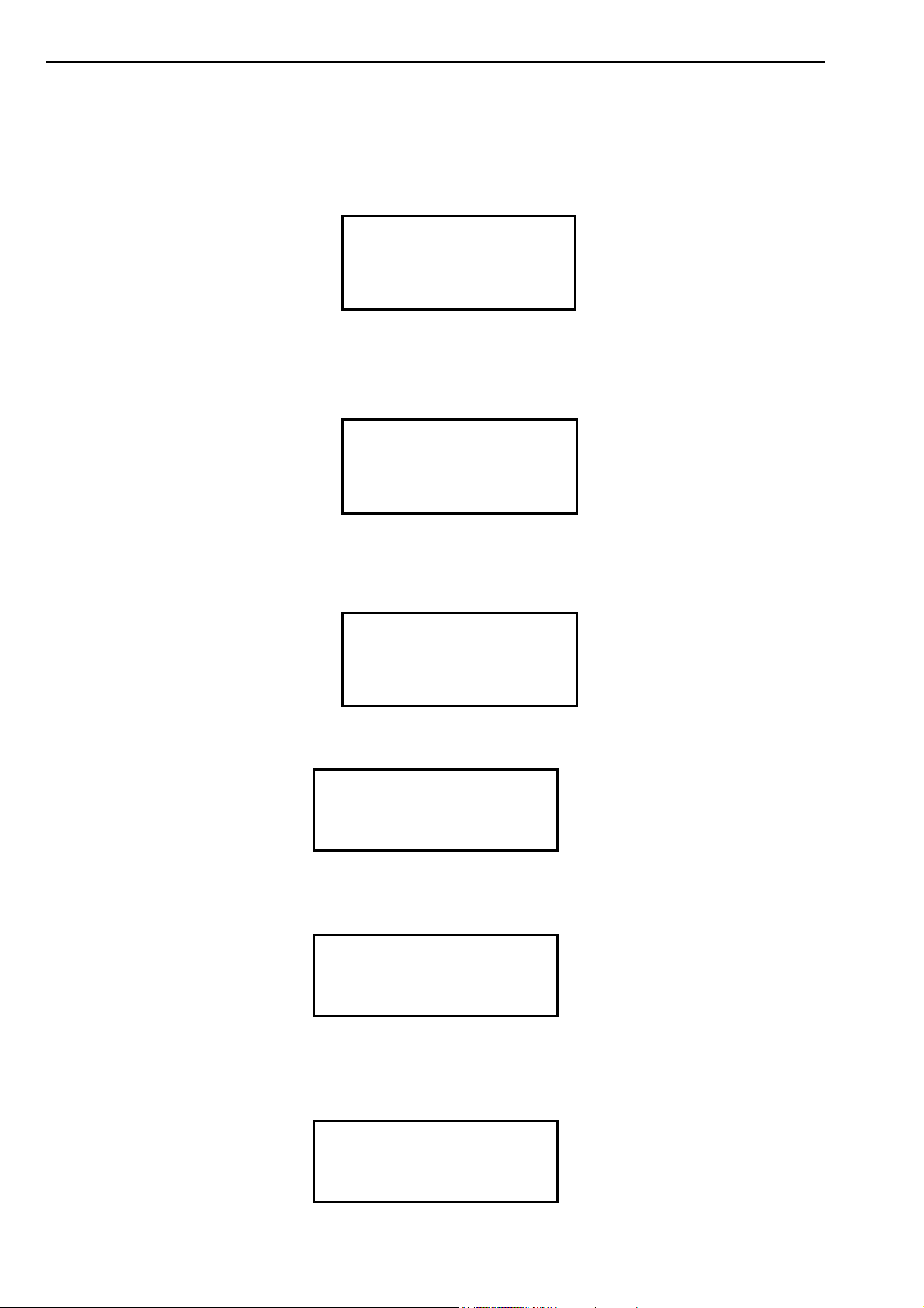
As soon as the control unit is switched on, the display notifies the operator that the
communication interface is initializing.
CAN INTERFACE
INIT
After the initialization of the communication interface, the control unit checks for the integrity
of the communication channel with the inverter. The following wait message is displayed until
the check is finished:
INVERTER COM CAN-BUS
NOT READY WAIT..
The following message is displayed once the working efficiency of the communication channel
has been checked.
INVERTER COM CAN-BUS
READY
Next, the mains frequency recognized by the control unit is displayed.
MAINS FREQUENCY
50 Hz
Both the type of control unit and the relevant software version are displayed.
TE700 REV. 1.09
WELD CONTROL UNIT
In order to complete the control unit switch-on sequence, the operator is asked to press the
RESTART button or to generate the RESTART sequence through external program recalls.
The displayed message is as follows.
PRESS RESTART
BUTTON [//]
18/128
Page 19
TECNA S.p.A. ITEM TE700 Instruction Manual
This RESTART button enables the control unit's commands and outputs. It must be pressed
every time the control unit is powered.
As soon as the RESTART command is issued, all the devices connected to the VAUX output
are supplied and the charging procedure for the capacitors bank is started on the inverter.
Before activating the RESTART command, it is important to check
that it will not cause damage to people or equipment.
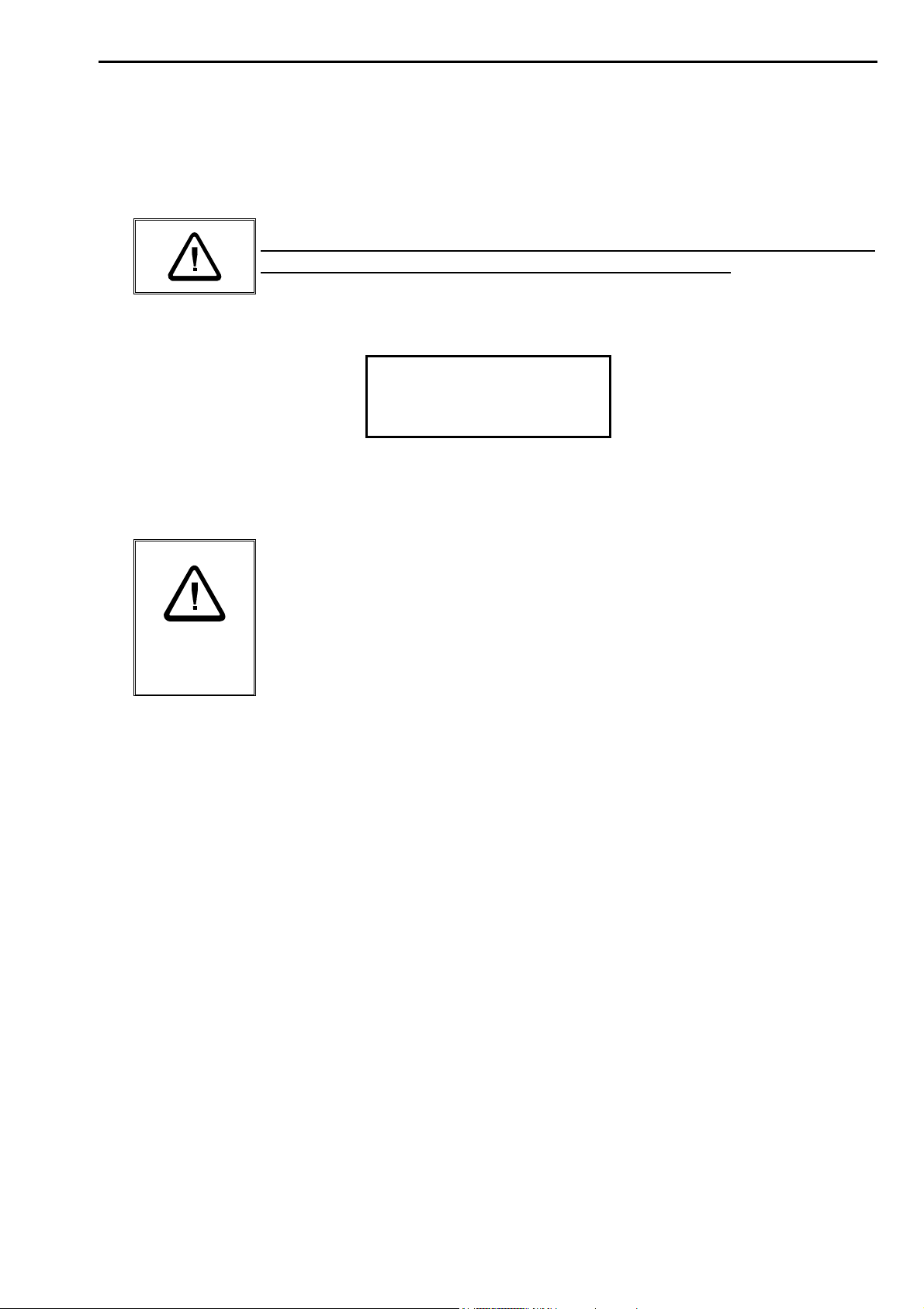
The following message is displayed until the inverter is ready to weld.
INVERTER CAPACITOR
CHARGING PLEASE WAIT
Before starting any welding operations, first program the welding data and set some general
operating parameters of the welder.
For safety reasons, the microprocessor does not start the welding
cycle if the cycle start signal is actuated when the welder is turned
on. Simply release the control and actuate it again. Micro-cutoffs or
excessive voltage drops do not alter the control unit's working
efficiency but stop it. To restore working efficiency, turn off the
machine and then turn it on again.
19/128
Page 20
Instruction Manual ITEM TE700 TECNA S.p.A.
CHAPTER 2 – CONTROL UNIT PROGRAMMING
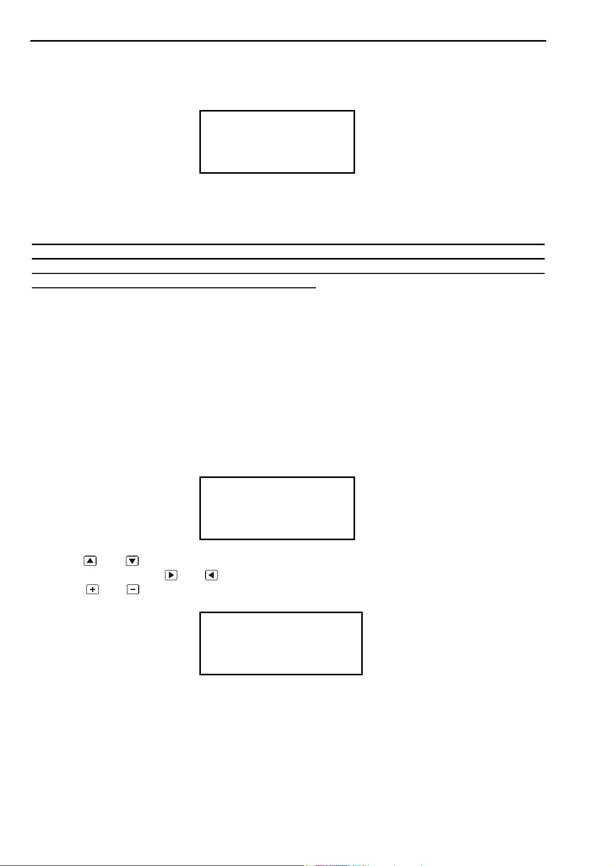
By placing the key in PROGRAM DATA position the following screen is displayed:
-TE700 VER. 1.09 ->PROGRAM DATA
SETUP MENU
STEPPER MENU
The first row reports the control unit type and the software version. Then the display lists all
the menus allowing accessing the various control unit functions.
The following list includes all the menus available in the control unit. However, it is
possible that not all of these menus are displayed by the control unit being used as
some of them depends either on the options actually inserted in the control unit or on
the welder type the control unit is installed onto.
_ PROGRAM DATA
_ SETUP MENU
_ STEPPER MENU
_ FEATURES TE700
_ FEATURES INVERTER
_ PROGRAM COPY
_ DIAGNOSTIC TE700
_ DIAGNOSTIC INV.
_ PROG. SEQUENCE
_ THICKNESS SENSE (It may be activated)
_ TIP-DRESSING (It may be activated)
-TE700 VER. 1.09 - PROGRAM DATA
>SETUP MENU
STEPPER MENU
Use keys
of the menus. Use keys
and to move up and down the > arrow cursor displayed on the left-hand side
and to enter and exit from the menu selected by the cursor.
Use keys and to modify the parameter indicated by the cursor.
PROGRAM DATA T1
PROGRAM N. 001
>PRG. NAME
TOOLS N° 1
20/128
Page 21
TECNA S.p.A. ITEM TE700 Instruction Manual
2.1 – PROGRAM DATA
-TE700 VER. 1.09->PROGRAM DATA
SETUP MENU
STEPPER MENU
The PROGRAM DATA menu contains all the weld cycle parameters, the times and the
currents which to carry out the welds with.
PROGRAM DATA T1
>PROGRAM N. 001
PRG. NAME
TOOLS N° 1
The first choice to make is the number of the program to be used. Choose among the 300
storable programs using the and keys.
After having selected the program number which to work with, use key to enter an
alphanumeric identifier associated with the number of the program so that it is easier to
recognize it during the recall or the display.
PROGRAM DATA T1
PROGRAM N. 001
>PRG. NAME USI1500P
TOOLS N° 1
Press key to select which character is to be entered or modified. Each time key is
pressed, the next character in the string is selected beginning from position 1 up to position
number 8. On reaching the eighth character, when key is pressed the operator may modify
the first character again.
PROGRAM DATA T1
PROGRAM N. 001
>PRG. NAME U<SI1500P
TOOLS N° 1
The affected character is indicated on the control unit display by the symbol "<" located on the
right-hand side of the character itself. In order to change the character, use keys and
and key [///]. The usable characters are the decimal numbers from 0 to 9, the space key and
the capital characters of the international alphabet from A to Z.
After having changed the name of the program to work with, use key to select the weld tool
number.
PROGRAM DATA T1
PROGRAM N. 001
PRG. NAME USI1500P
>TOOLS N° 1
The values of the parameter may range from 1 up to 4 at the most. The max value is set
inside the FEATURES INVERTER menu and is included between 1 and 4 (N.WELDING
21/128
Page 22
Instruction Manual ITEM TE700 TECNA S.p.A.
TRAFO). If 1 was set as max value, the value of the parameter cannot be changed by the
operator.
The WELD TOOL parameter permits identifying up to max 4 different types of electrodes
used during the welding operations.
The electrodes may be interchanged on the same welding head and, as such, share the same
welding transformer or they can be installed on different welding heads having different
welding transformers connected to the same welding unit.
An independent spot counter is associated with each WELD TOOL, which increases only
when the control unit welds with a program in which the corresponding WELD TOOL is
selected.
This allows the control unit to manage 4 different current increments or electrodes dressing
procedures, in which the current increment or electrode wear is calculated considering only
the weld spots carried out by that specific electrode ignoring the weld spots carried out with
other electrodes.
PROGRAM DATA T2
PROGRAM N. 001
PRG. NAME USI1500P
>TOOLS N° 2
The modification of the WELD TOOL number is indicated next to the PROGRAM DATA text
by means of the symbols T1, T2, T3, T4 so that, on scrolling the weld program parameters,
the operator may always see which tool identifier is associated with the weld program being
used.
PROGRAM DATA T1
PRG. NAME USI1500P
TOOLS N° 1
>WORKING MODE IK
Then the next parameters are searched for, using keys and to set the required value,
one at a time, using keys
and .
As such all the parameters will be set to the desired value for carrying out the welding
process.
Please, beware that the data is saved only and exclusively if the program is exited or if the
key is turned in RUN position.
Below the six WORKING MODEs are described and the six programming screens are
displayed according to the parameter selected in the WORKING MODE. The screens contain
all the programmable parameters.
The number of available WORKING MODEs may change depending on the configuration of
the spot welder on which the control unit is installed.
22/128
Page 23
TECNA S.p.A. ITEM TE700 Instruction Manual
2.2 - CONSTANT CURRENT OPERATING MODE (IK)
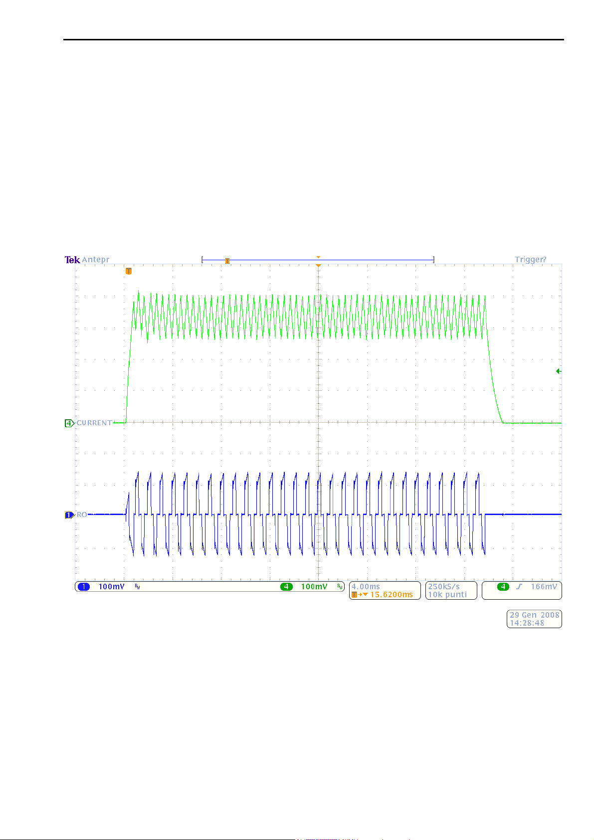
When the weld control unit works in constant current mode, the current value which to carry
out the welding with may be set directly. During the welding procedure, the control unit
measures the real effective value (RMS) of the welding current every mS and maintains the
set current according to a mathematical correction algorithm. The max welding current value
that may be set is restricted automatically to the max current than can be supplied by the
welding transformer set in the FEATURES INVERTER menu.
In addition to simplifying the programming operations, this WORKING MODE also permits to
keep the desired welding current even if some factors change such as: mains voltage,
welding circuit dimensions and impedance, conditions of the welding tools or surface
condition of the materials being processed.
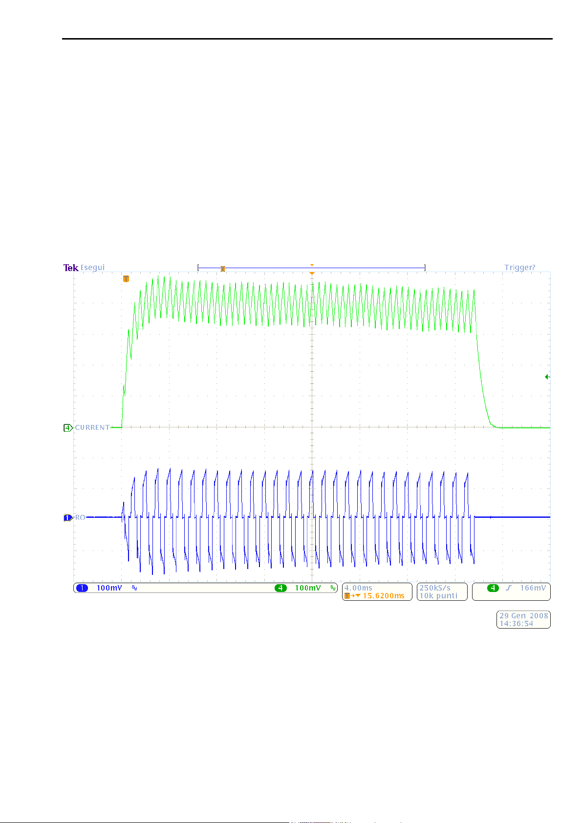
The above image shows the welding current maintained by the constant adjustment
mathematical algorithm. Notice that the current slicing (RO) of the inverter changes during the
welding operation to keep the welding current constant.
23/128
Page 24
Instruction Manual ITEM TE700 TECNA S.p.A.
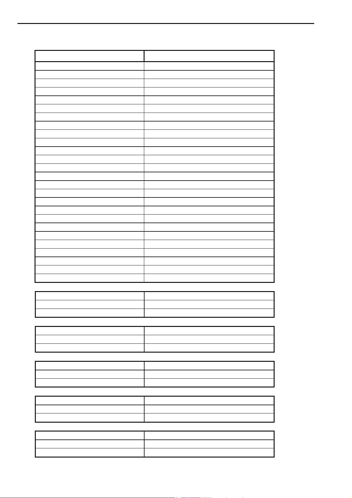
TABLE WITH CONSTANT CURRENT OPERATING MODE PARAMETERS
PARAMETER RANGE VALUE
PROGRAM N. 001 – 300
WORKING MODE IK
CONTROL MODE * NO
QUALITY – T* OFF
QUALITY – R * OFF
SQUEEZE 1 0.5 – 99.0 cycles
SQUEEZE 00.0 – 99.0 cycles
PRESSURE 00.5 – 10.0 bar
FORGE DELAY 00 – 99 cycles
FORG.PRESS. 00.5 – 10.0 bar
PRE-WELD 0000 – 1000 mS
PRE-CURR. 000.30 – 200.00 KA
COLD 1 0000 – 1000 mS
SLOPE UP 0000 – 1000 mS
WELD 0001 – 2000 mS
CURRENT 000.30 – 200.00 KA
COLD 2 0000 – 1000 mS
IMPULSE N. 1 – 9
WELD 2 0000 – 1000 mS
CURRENT 2 000.30 – 200.00 KA
SLOPE DOWN 0000 – 1000 mS
COLD 3 0000 – 1000 mS
POST-WELD 0000 – 1000 mS
POST-CURR. 000.30 – 200.00 KA
HOLD TIME 00.5 – 99.0 cycles
OFF TIME 00.0 – 99.0 cycles
CONTROL MODE * CUR
LIM I MIN 000.30 – 200.00 KA
LIM I MAX 000.30 – 200.00 KA
CONTROL MODE * RO
LIM RO MIN 005.0 – 100.0%
LIM RO MAX 005.0 – 100.0%
CONTROL MODE * VE
LIM V MIN 00.20 – 20.00 V
LIM V MAX 00.20 – 20.00 V
CONTROL MODE * PW
LIM P MIN 000.20 - 600.00 KW
LIM P MAX 000.20 – 600.00 KW
CONTROL MODE * ENE
LIM E MIN 00000 – 60000 J
LIM E MAX 00000 – 60000 J
24/128
Page 25

TECNA S.p.A. ITEM TE700 Instruction Manual
QUALITY –T * THICK
THICK. MIN 00.00 – 60.00 mm
THICK MAX 00.00 – 60.00 mm
QUALITY –T * IDENT
IDENT. MIN 0.000 – 6.000 mm
IDENT. MAX 0.000 – 6.000 mm
QUALITY –T * TH+ID
THICK. MIN 00.00 – 60.00 mm
THICK MAX 00.00 – 60.00 mm
IDENT. MIN 0.000 – 6.000 mm
IDENT. MAX 0.000 – 6.000 mm
QUALITY –T * ZERO
QUALITY –R * PRE
RMIN PRE 0 – 60000uOhm
RMAX PRE 0 – 60000uOhm
QUALITY –R * POST
RMIN POST 0 – 60000uOhm
RMAX POST 0 – 60000uOhm
QUALITY –R * PRE+POST
RMIN PRE 0 – 60000uOhm
RMAX PRE 0 – 60000uOhm
RMIN POST 0 – 60000uOhm
RMAX POST 0 – 60000uOhm
QUALITY –R * ZERO
There are some special conditions:
On setting the OFF TIME to zero, the control unit will work in single cycle.
On setting the PRE-WELD parameter to zero, the pre-welding process will not be carried
out.
On setting the POST-WELD parameter to zero, the post-welding process will not be
carried out.
On setting the WELD 2 parameter to zero, WELD 2 will not be carried out.
On setting LIM I MIN and LIM I MAX to the same value, the limits are deactivated.
On setting LIM RO MIN and LIM RO MAX to the same value, the limits are deactivated.
On setting LIM V MIN and LIM V MAX to the same value, the limits are deactivated.
On setting LIM P MIN and LIM P MAX to the same value, the limits are deactivated.
On setting LIM E MIN and LIM E MAX to the same value, the limits are deactivated.
On setting THICK. MIN and THICK. MAX to the same value, the limits are deactivated.
On setting IDENT. MIN and IDENT. MAX to the same value, the limits are deactivated.
On setting RMIN PRE and RMAX PRE to the same value, the limits are deactivated.
On setting RMIN POST and RMAX POST to the same value, the limits are deactivated.
It is advisable to activate the CONTROL UNIT in RO MODE and to check the limit use
conditions before proceeding with production. For instance, if use is meant to be with 2
25/128
Page 26

Instruction Manual ITEM TE700 TECNA S.p.A.
sheets, the limit conditions are either with 1 or 3 sheets. The constant welding current is
adjusted by the TE700 control unit (if the value of the r parameter for using the welding unit is
less than 100.0%). The operator must then check the values of the r indicator when welding
with 1 sheet and set this value as minimum limit and if welding with 3 sheets, set this value as
maximum limit.
If a more accurate spot quality control is required, activate the QUALITY-T parameters to
check the initial thickness of the sheets and the electrode penetration at the end of the
welding cycle, and the QUALITY-R parameter to obtain a measurement of the initial and final
values of the resistance.
The presence of the QUALITY-T and QUALITY-R parameters depends on the control unit's
configuration and which spot welder is used.
However, it is not possible to undoubtedly assure that the piece has been effectively
welded, as all the conditions and parameters involved in the welding process
execution should be checked.
26/128
Page 27
TECNA S.p.A. ITEM TE700 Instruction Manual
2.3 – FIX OPERATING MODE (FIX)
In FIX working mode the inverter welding unit does not make any adjustments to the current
supplied during welding. The operator must set the power slicing percentage supplied by the
inverter, which ranges from 5% to 100%. The power supplied during the welding operation
increases for higher slicing values.
In this case the current actually supplied by the inverter involves various factors and is no
longer constant.
The factors that might affect the current supply are: changes in the resistance of the material
to be welded, wearing out of the electrodes and changes in the geometry of the secondary
circuit or mains voltage fluctuations.
The FIX WORKING MODE may be advisable for short-term welding with great resistance
changes or when using the welder as a metal-heating device.
The slicing of the inverter (RO) is kept constant. The slicing is understood to be the
relationship between the switch-on time of the IGBT power devices and their OFF time. The
current supplied to the secondary circuit is no longer constant but depends on the resistance
of the secondary circuit and on the resistance of the material to be welded.
27/128
Page 28
Instruction Manual ITEM TE700 TECNA S.p.A.
TABLE WITH FIX OPERATING MODE PARAMETERS
PARAMETER RANGE VALUE
PROGRAM N. 001 – 300
WORKING MODE FIX
CONTROL MODE * NO
QUALITY – T* OFF
QUALITY – R * OFF
SQUEEZE 1 0.5 – 99.0 cycles
SQUEEZE 00.0 – 99.0 cycles
PRESSURE 00.5 – 10.0 bar
FORGE DELAY 00 – 99 cycles
FORG.PRESS. 00.5 – 10.0 bar
PRE-WELD 0000 – 1000 mS
PRE-RO 005.0 – 100.0 %
COLD 1 0000 – 1000 mS
SLOPE UP 0000 – 1000 mS
WELD 0001 – 2000 mS
RO 005.0 – 100.0 %
COLD 2 0000 – 1000 mS
IMPULSE N. 1 – 9
WELD 2 0000 – 1000 mS
RO 2 005.0 – 100.0 %
SLOPE DOWN 0000 – 1000 mS
COLD 3 0000 – 1000 mS
POST-WELD 0000 – 1000 mS
POST-RO 005.0 – 100.0 %
HOLD TIME 00.5 – 99.0 cycles
OFF TIME 00.0 – 99.0 cycles
CONTROL MODE * CUR
LIM I MIN 000.30 – 200.00 KA
LIM I MAX 000.30 – 200.00 KA
CONTROL MODE * RO
LIM RO MIN 005.0 – 100.0%
LIM RO MAX 005.0 – 100.0%
CONTROL MODE * VE
LIM V MIN 00.20 – 20.00 V
LIM V MAX 00.20 – 20.00 V
CONTROL MODE * PW
LIM P MIN 000.20 - 600.00 KW
LIM P MAX 000.20 – 600.00 KW
CONTROL MODE * ENE
LIM E MIN 00000 – 60000 J
LIM E MAX 00000 – 60000 J
28/128
Page 29
TECNA S.p.A. ITEM TE700 Instruction Manual
QUALITY –T * THICK
THICK. MIN 00.00 – 60.00 mm
THICK MAX 00.00 – 60.00 mm
QUALITY –T * IDENT
IDENT. MIN 0.000 – 6.000 mm
IDENT. MAX 0.000 – 6.000 mm
QUALITY –T * TH+ID
THICK. MIN 00.00 – 60.00 mm
THICK MAX 00.00 – 60.00 mm
IDENT. MIN 0.000 – 6.000 mm
IDENT. MAX 0.000 – 6.000 mm
QUALITY –T * ZERO
QUALITY –R * PRE
RMIN PRE 0 – 60000uOhm
RMAX PRE 0 – 60000uOhm
QUALITY –R * POST
RMIN POST 0 – 60000uOhm
RMAX POST 0 – 60000uOhm
QUALITY –R * PRE+POST
RMIN PRE 0 – 60000uOhm
RMAX PRE 0 – 60000uOhm
RMIN POST 0 – 60000uOhm
RMAX POST 0 – 60000uOhm
QUALITY –R * ZERO
There are some special conditions:
On setting the OFF TIME to zero, the control unit will work in single cycle.
On setting the PRE-WELD parameter to zero, the pre-welding process will not be carried
out.
On setting the POST-WELD parameter to zero, the post-welding process will not be
carried out.
On setting WELD 2 parameter to zero, WELD 2 will not be carried out.
On setting LIM I MIN and LIM I MAX to the same value, the limits are deactivated.
On setting LIM RO MIN and LIM RO MAX to the same value, the limits are deactivated.
On setting LIM V MIN and LIM V MAX to the same value, the limits are deactivated.
On setting LIM P MIN and LIM P MAX to the same value, the limits are deactivated.
On setting LIM E MIN and LIM E MAX to the same value, the limits are deactivated.
On setting THICK. MIN and THICK. MAX to the same value, the limits are deactivated.
On setting IDENT. MIN and IDENT. MAX to the same value, the limits are deactivated.
On setting RMIN PRE and RMAX PRE to the same value, the limits are deactivated.
On setting RMIN POST and RMAX POST to the same value, the limits are deactivated
In the FIX WORKING MODE, and current slicing being the same, the current supplied by the
inverter depends exclusively on the resistance of the secondary area and on the resistance of
29/128
Page 30

Instruction Manual ITEM TE700 TECNA S.p.A.
the material to be welded. This condition applies as long as the welding current is less than
the maximum current of the welding transformer. If the welding current tends to exceed the
value set as welding transformer max current, the welder intervenes automatically by reducing
the set current slicing value in real time to maintain current within the set limits.
30/128
Page 31
TECNA S.p.A. ITEM TE700 Instruction Manual
2.4 - CONSTANT SECONDARY VOLTAGE OPERATING MODE (VEK)
When working with constant secondary voltage, the welder calculates the real effective value
(RMS) of the voltage at the electrodes every mS and keeps the set voltage value constant
according to a mathematical algorithm. The value of the current supplied by the inverter is
consequently inversely proportional to the resistance of the secondary circuit and to the
resistance of the material to be welded. The value of the supplied current will be independent
from power line fluctuations. The secondary voltage is kept constant as long as it is lower than
the CURR. MAX parameter. If the welding current tends to exceed the value set in CURR.
MAX., the inverter unit will automatically decrease the value of the secondary voltage in real
time to maintain the welding current within the set limits. The CURR. MAX. value may be set
as high as the max value of the transformer welding current. Its task is to prevent damage to
the welding tools in the case of harsh changes in the resistance of the material to be welded.
The constant secondary voltage working mode may be used for welds with tungsten
electrodes or to compensate the wear of the electrodes during the welding operation.
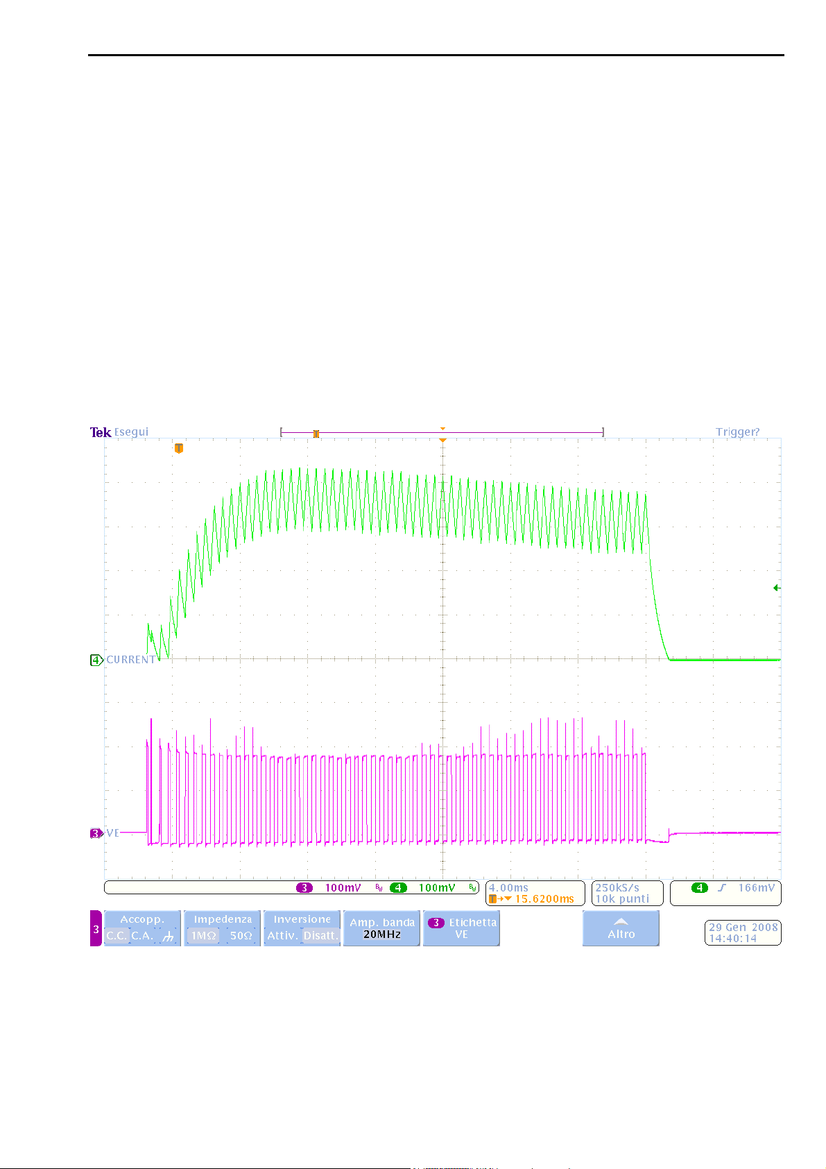
The VE value remains constant during the welding operation, but the current value changes
according to the impedance of the secondary circuit.
31/128
Page 32
Instruction Manual ITEM TE700 TECNA S.p.A.
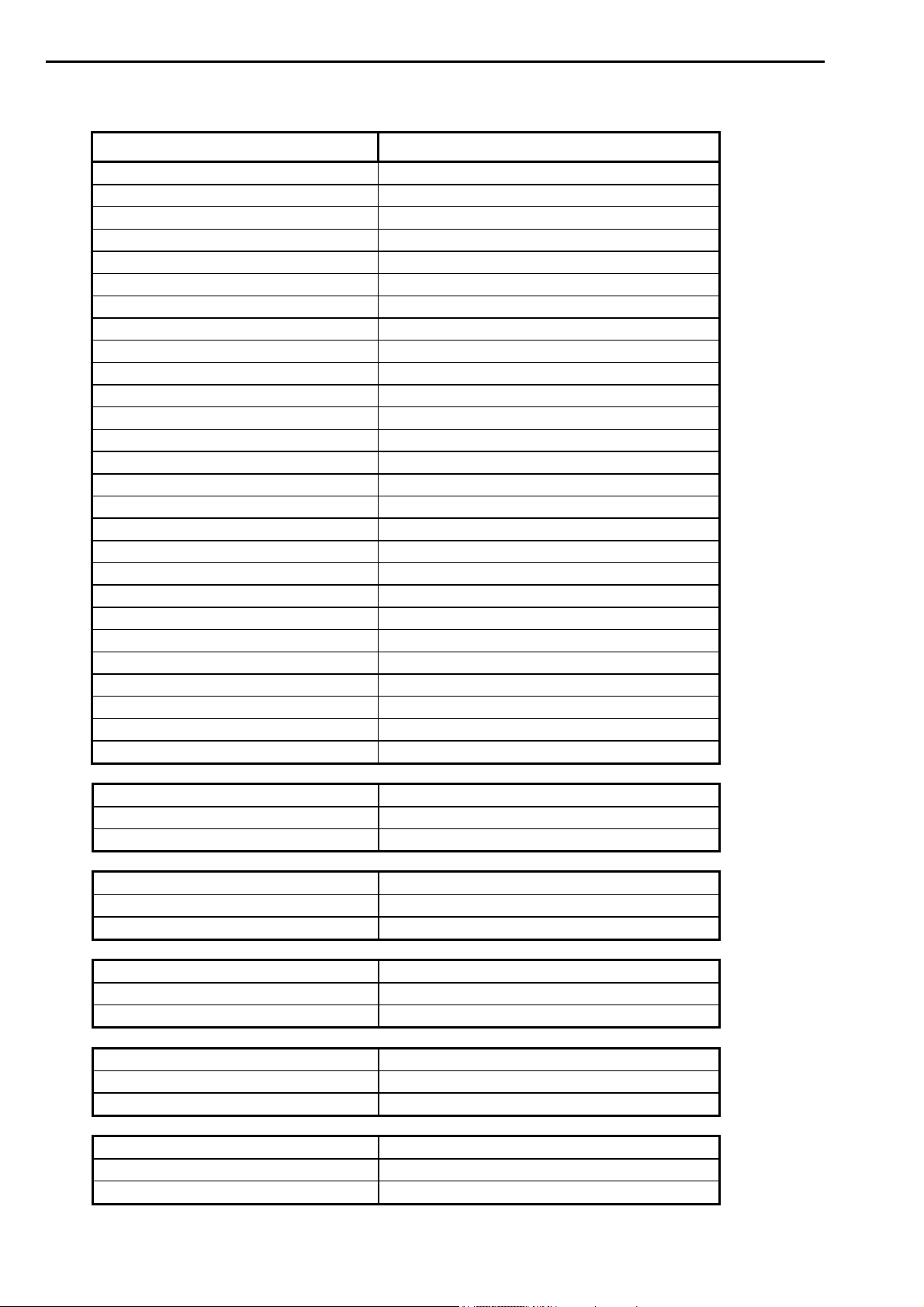
TABLE WITH CONSTANT SECONDARY VOLTAGE OPERATING MODE PARAMETERS
PARAMETER RANGE VALUE
PROGRAM N. 001 – 300
WORKING MODE VEK
CONTROL MODE * NO
QUALITY – T* OFF
QUALITY – R * OFF
SQUEEZE 1 0.5 – 99.0 cycles
SQUEEZE 00.0 – 99.0 cycles
PRESSURE 00.5 – 10.0 bar
FORGE DELAY 00 – 99 cycles
FORG.PRESS. 00.5 – 10.0 bar
PRE-WELD 0000 – 1000 mS
PRE-VE 00.20 – 20.00 V
COLD 1 0000 – 1000 mS
SLOPE UP 0000 – 1000 mS
WELD 0001 – 2000 mS
VE 00.20 – 20.00 V
CURR. MAX. 001.00 – 200.00 KA
COLD 2 0000 – 1000 mS
IMPULSE N. 1 – 9
WELD 2 0000 – 1000 mS
VE 2 00.20 – 20.00 V
SLOPE DOWN 0000 – 1000 mS
COLD 3 0000 – 1000 mS
POST-WELD 0000 – 1000 mS
POST-VE 00.20 – 20.00 V
HOLD TIME 00.5 – 99.0 cycles
OFF TIME 00.0 – 99.0 cycles
CONTROL MODE * CUR
LIM I MIN 000.30 – 200.00 KA
LIM I MAX 000.30 – 200.00 KA
CONTROL MODE * RO
LIM RO MIN 005.0 – 100.0%
LIM RO MAX 005.0 – 100.0%
CONTROL MODE * VE
LIM V MIN 00.20 – 20.00 V
LIM V MAX 00.20 – 20.00 V
CONTROL MODE * PW
LIM P MIN 000.20 - 600.00 KW
LIM P MAX 000.20 – 600.00 KW
CONTROL MODE * ENE
LIM E MIN 00000 – 60000 J
LIM E MAX 00000 – 60000 J
32/128
Page 33
TECNA S.p.A. ITEM TE700 Instruction Manual
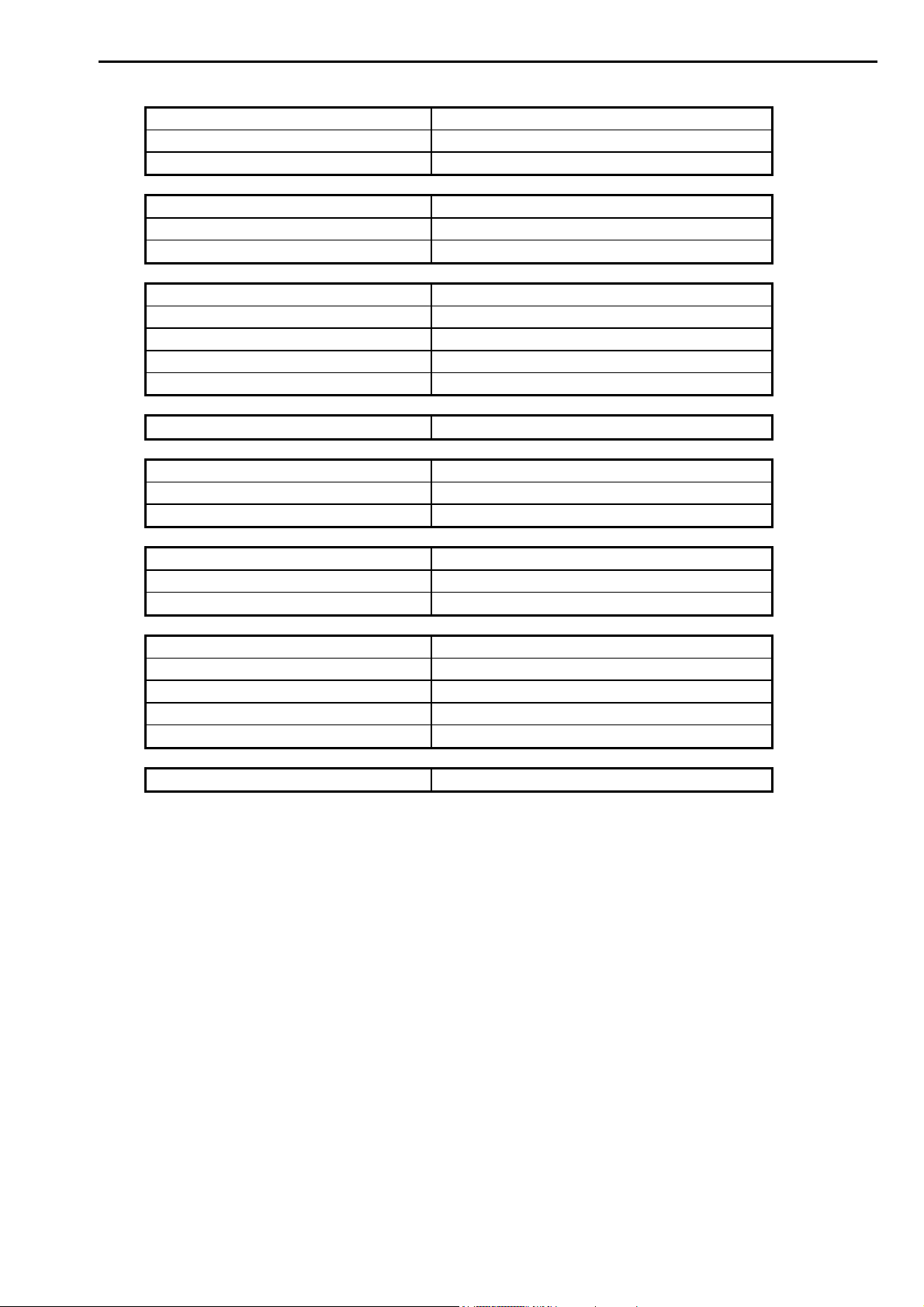
QUALITY –T * THICK
THICK. MIN 00.00 – 60.00 mm
THICK MAX 00.00 – 60.00 mm
QUALITY –T * IDENT
IDENT. MIN 0.000 – 6.000 mm
IDENT. MAX 0.000 – 6.000 mm
QUALITY –T * TH+ID
THICK. MIN 00.00 – 60.00 mm
THICK MAX 00.00 – 60.00 mm
IDENT. MIN 0.000 – 6.000 mm
IDENT. MAX 0.000 – 6.000 mm
QUALITY –T * ZERO
QUALITY –R * PRE
RMIN PRE 0 – 60000uOhm
RMAX PRE 0 – 60000uOhm
QUALITY –R * POST
RMIN POST 0 – 60000uOhm
RMAX POST 0 – 60000uOhm
QUALITY –R * PRE+POST
RMIN PRE 0 – 60000uOhm
RMAX PRE 0 – 60000uOhm
RMIN POST 0 – 60000uOhm
RMAX POST 0 – 60000uOhm
QUALITY –R * ZERO
There are some special conditions:
On setting the OFF TIME to zero, the control unit will work in single cycle.
On setting the PRE-WELD parameter to zero, the pre-welding process will not be carried
out.
On setting the POST-WELD parameter to zero, the post-welding process will not be
carried out.
On setting WELD 2 parameter to zero, WELD 2 will not be carried out.
On setting LIM I MIN and LIM I MAX to the same value, the limits are deactivated.
On setting LIM RO MIN and LIM RO MAX to the same value, the limits are deactivated.
On setting LIM V MIN and LIM V MAX to the same value, the limits are deactivated.
On setting LIM P MIN and LIM P MAX to the same value, the limits are deactivated.
On setting LIM E MIN and LIM E MAX to the same value, the limits are deactivated.
On setting THICK. MIN and THICK. MAX to the same value, the limits are deactivated.
On setting IDENT. MIN and IDENT. MAX to the same value, the limits are deactivated.
On setting RMIN PRE and RMAX PRE to the same value, the limits are deactivated.
On setting RMIN POST and RMAX POST to the same value, the limits are deactivated
33/128
Page 34
Instruction Manual ITEM TE700 TECNA S.p.A.
2.5 – CONSTANT POWER OPERATING MODE (PWK)
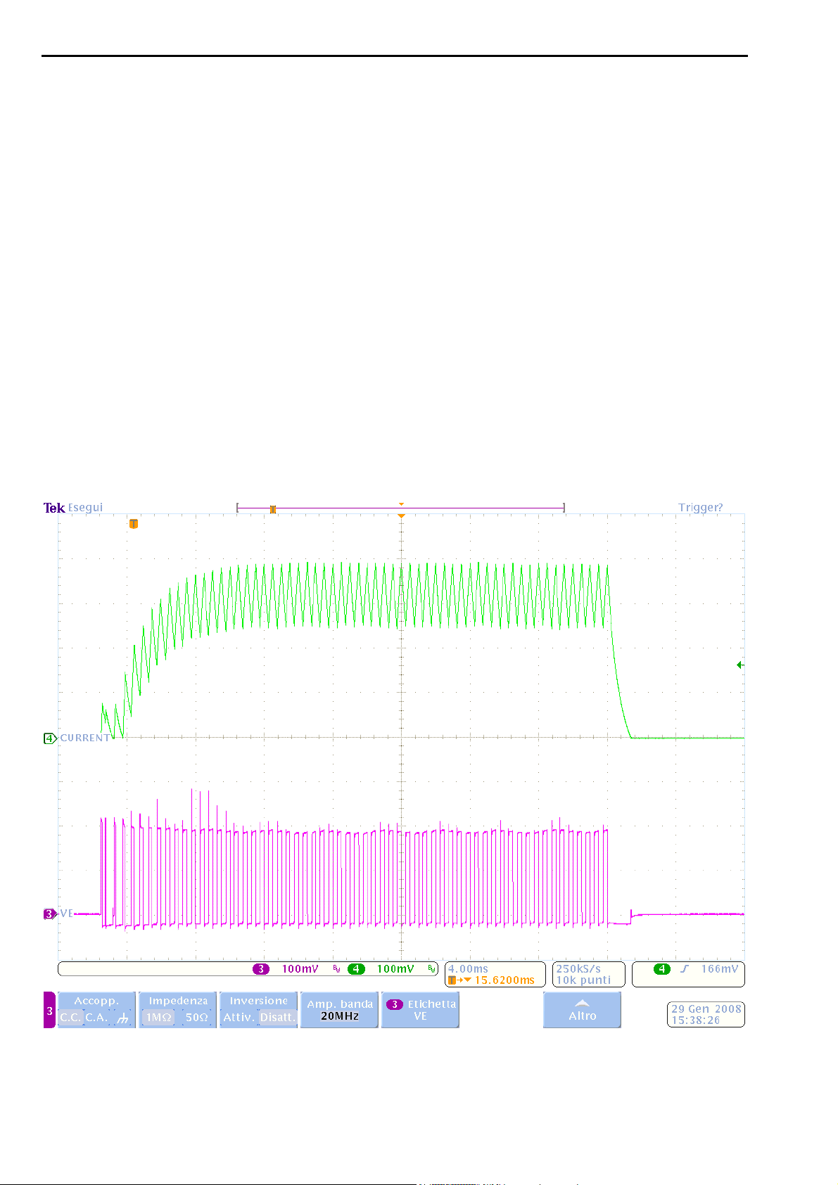
When working in constant power mode, the inverter calculates the real effective value (RMS)
of the secondary voltage and the secondary current every mS and maintains the product
constant through a mathematical algorithm during mains voltage changes. Consequently if the
secondary resistance decreases, the welding current will increase and vice versa when the
secondary resistance increases the welding current will decrease. The adjustment in constant
power works correctly until the welding current reaches the current value set in the CURR.
MAX. parameter. On attaining said limit, the inverter automatically reduces the supplied power
in real time to limit the value of the supplied current. The supplied welding current may never
exceed the max value set for the used welding transformer. Using constant power may be
seen as a constant energy welding at a known time. In fact, when working with constant
power during the welding operation, a constant energy value is always supplied at a fixed
time.
The use of the constant power working mode may be useful to compensate the wear of the
electrodes or to weld materials that are subjected to significant resistance changes during the
welding process such as, for instance, rod welding or highly-resistive metal welding. In these
cases the current decreases during the initial welding phase in which the resistance of the
material is typically higher. As such, the squirting of molten material is avoided, phenomena
that reduce the quality of the weld.
You can see the inconstancy of the current and secondary voltage to maintain constant the
product of the two quantities and, as such, the supplied power.
34/128
Page 35
TECNA S.p.A. ITEM TE700 Instruction Manual
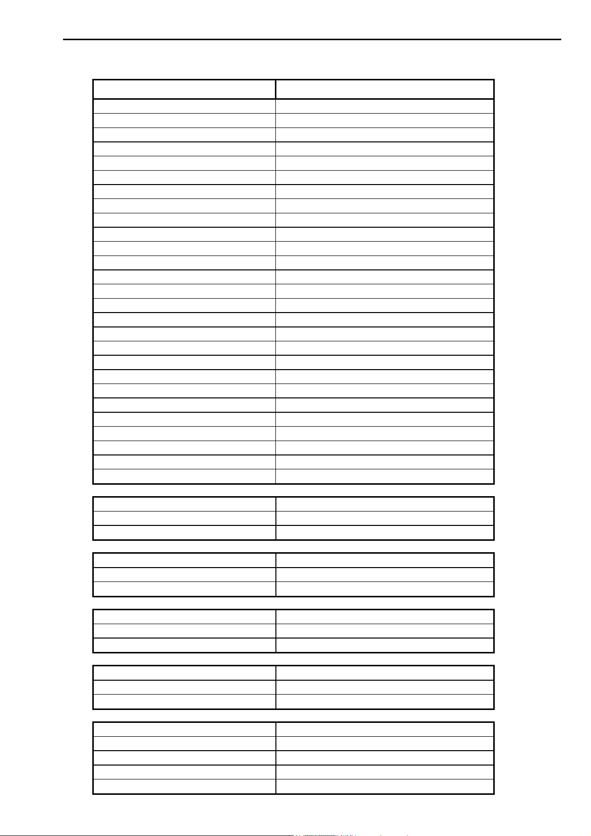
TABLE WITH CONSTANT POWER OPERATING MODE PARAMETERS
PARAMETER RANGE VALUE
PROGRAM N. 001 – 300
WORKING MODE PWK
CONTROL MODE * NO
QUALITY – T* OFF
QUALITY – R * OFF
SQUEEZE 1 0.5 – 99.0 cycles
SQUEEZE 00.0 – 99.0 cycles
PRESSURE 00.5 – 10.0 bar
FORGE DELAY 00 – 99 cycles
FORG.PRESS. 00.5 – 10.0 bar
PRE-WELD 0000 – 1000 mS
PRE-POWER 000.20 – 600.00 KW
COLD 1 0000 – 1000 mS
SLOPE UP 0000 – 1000 mS
WELD 0001 – 2000 mS
POWER 000.20 – 600.00 KW
CURR. MAX. 001.00 – 200.00 KA
COLD 2 0000 – 1000 mS
IMPULSE N. 1 – 9
WELD 2 0000 – 1000 mS
POWER 2 000.20 – 600.00 KW
SLOPE DOWN 0000 – 1000 mS
COLD 3 0000 – 1000 mS
POST-WELD 0000 – 1000 mS
POST-POWER 000.20 – 600.00 KW
HOLD TIME 00.5 – 99.0 cycles
OFF TIME 00.0 – 99.0 cycles
CONTROL MODE * CUR
LIM I MIN 000.30 – 200.00 KA
LIM I MAX 000.30 – 200.00 KA
CONTROL MODE * RO
LIM RO MIN 005.0 – 100.0%
LIM RO MAX 005.0 – 100.0%
CONTROL MODE * VE
LIM V MIN 00.20 – 20.00 V
LIM V MAX 00.20 – 20.00 V
CONTROL MODE * PW
LIM P MIN 000.20 - 600.00 KW
LIM P MAX 000.20 – 600.00 KW
CONTROL MODE * ENE
LIM E MIN 00000 – 60000 J
LIM E MAX 00000 – 60000 J
QUALITY –T * THICK
THICK. MIN 00.00 – 60.00 mm
35/128
Page 36
Instruction Manual ITEM TE700 TECNA S.p.A.
THICK MAX 00.00 – 60.00 mm
QUALITY –T * IDENT
IDENT. MIN 0.000 – 6.000 mm
IDENT. MAX 0.000 – 6.000 mm
QUALITY –T * TH+ID
THICK. MIN 00.00 – 60.00 mm
THICK MAX 00.00 – 60.00 mm
IDENT. MIN 0.000 – 6.000 mm
IDENT. MAX 0.000 – 6.000 mm
QUALITY –T * ZERO
QUALITY –R * PRE
RMIN PRE 0 – 60000uOhm
RMAX PRE 0 – 60000uOhm
QUALITY –R * POST
RMIN POST 0 – 60000uOhm
RMAX POST 0 – 60000uOhm
QUALITY –R * PRE+POST
RMIN PRE 0 – 60000uOhm
RMAX PRE 0 – 60000uOhm
RMIN POST 0 – 60000uOhm
RMAX POST 0 – 60000uOhm
QUALITY –R * ZERO
There are some special conditions:
On setting the OFF TIME to zero, the control unit will work in single cycle.
On setting the PRE-WELD parameter to zero, the pre-welding process will not be carried
out.
On setting the POST-WELD parameter to zero, the post-welding process will not be
carried out.
On setting WELD 2 parameter to zero, WELD 2 will not be carried out.
On setting LIM I MIN and LIM I MAX to the same value, the limits are deactivated.
On setting LIM RO MIN and LIM RO MAX to the same value, the limits are deactivated.
On setting LIM V MIN and LIM V MAX to the same value, the limits are deactivated.
On setting LIM P MIN and LIM P MAX to the same value, the limits are deactivated.
On setting LIM E MIN and LIM E MAX to the same value, the limits are deactivated.
On setting THICK. MIN and THICK. MAX to the same value, the limits are deactivated.
On setting IDENT. MIN and IDENT. MAX to the same value, the limits are deactivated.
On setting RMIN PRE and RMAX PRE to the same value, the limits are deactivated.
On setting RMIN POST and RMAX POST to the same value, the limits are deactivated
36/128
Page 37

TECNA S.p.A. ITEM TE700 Instruction Manual
2.6 – CONSTANT ENERGY OPERATING MODE (ENE)
With a constant energy control unit, all the settings are made as for conventional control units
except for the ENERGY parameter and the welding time parameter, where a set rating is not
required but minimum and maximum ratings are set.
The inverter constantly adjusts the welding current to match it with the set value. During the
welding operations, the inverter detects the real effective value (RMS) of the welding current,
the non-inductive component of the voltage at the electrodes in volts and the welding duration
in mS. The product of I x V x time gives the thermal energy produced during welding,
expressed in joules (W x sec).
Since the energy subtracted by conduction and that dissipated between the external sheets
and the electrodes, reduce the precision of the energy measured, it is advisable to weld with
short timings and high electrode force. Therefore it is important, for good execution of the spot
quality control, that the welding machine it is applied to has adequate specifications relating to
power, electrode force and welding current for the execution of high A and B class spots.
To ensure correct use of the control unit in this working mode, we recommend following the
procedure below step by step:
1. adjust the welding pressure, the welding current and the diameter of the
electrodes according to the traditional tables for the execution of the required
welding.
2. disable the stepper function or the dressing function if activated.
3. set AUTORETAIN ON
4. set the control unit to work in constant current mode.
5. carry one spot weld out and verify that it is satisfactory.
6. read the total developed energy value on the control unit.
7. set the control unit to work in constant energy mode.
8. set the energy value read in the ENERGY parameter of the work program.
9. adjust the minimum time (T. MIN. WELD.) equal to the number of mS required to
carry out the spot with the new electrodes.
10. adjust the maximum time (T. MAX. WELD.) equal to a number of mS that will not
damage the piece to be welded.
ENERGY TREND READINGS DURING WELDING
1400
1200
E
1000
n
800
e
r
600
g
400
y
200
0
02468101214
mS
TABLE WITH CONSTANT ENERGY OPERATIONG MODE PARAMETERS
37/128
Page 38
Instruction Manual ITEM TE700 TECNA S.p.A.
PARAMETER RANGE VALUE
PROGRAM N. 001 – 300
WORKING MODE ENE
CONTROL MODE * NO
QUALITY – T* OFF
QUALITY – R * OFF
SQUEEZE 1 0.5 – 99.0 cycles
SQUEEZE 00.0 – 99.0 cycles
PRESSURE 00.5 – 10.0 bar
FORGE DELAY 00 – 99 cycles
FORG.PRESS. 00.5 – 10.0 bar
PRE-WELD 0000 – 1000 mS
PRE-CURR. 000.30 – 200.00 KA
COLD 1 0000 – 1000 mS
SLOPE UP 0000 – 1000 mS
CURRENT 000.30 – 200.00 KA
ENERGY 0 – 60000 J
WELD. MIN. 0001 – 999 mS
WELD. MAX. 0002 – 1000 mS
COLD 2 0000 – 1000 mS
IMPULSE N. 1 – 9
WELD 2 0000 – 1000 mS
CURRENT 2 000.30 – 200.00 KA
SLOPE DOWN 0000 – 1000 mS
COLD 3 0000 – 1000 mS
POST-WELD. 0000 – 1000 mS
POST-CURR. 000.30 – 200.00 KA
HOLD TIME 00.5 – 99.0 cycles
OFF TIME 00.0 – 99.0 cycles
CONTROL MODE * CUR
LIM I MIN 000.30 – 200.00 KA
LIM I MAX 000.30 – 200.00 KA
CONTROL MODE * RO
LIM RO MIN 005.0 – 100.0%
LIM RO MAX 005.0 – 100.0%
CONTROL MODE * VE
LIM V MIN 00.20 – 20.00 V
LIM V MAX 00.20 – 20.00 V
CONTROL MODE * PW
LIM P MIN 000.20 - 600.00 KW
LIM P MAX 000.20 – 600.00 KW
QUALITY –T * THICK
38/128
Page 39
TECNA S.p.A. ITEM TE700 Instruction Manual
THICK. MIN 00.00 – 60.00 mm
THICK MAX 00.00 – 60.00 MM
QUALITY –T * IDENT
IDENT. MIN 0.000 – 6.000 mm
IDENT. MAX 0.000 – 6.000 mm
QUALITY –T * TH+ID
THICK. MIN 00.00 – 60.00 mm
THICK MAX 00.00 – 60.00 MM
IDENT. MIN 0.000 – 6.000 mm
IDENT. MAX 0.000 – 6.000 mm
QUALITY –T * ZERO
QUALITY –R * PRE
RMIN PRE 0 – 60000uOhm
RMAX PRE 0 – 60000uOhm
QUALITY –R * POST
RMIN POST 0 – 60000uOhm
RMAX POST 0 – 60000uOhm
QUALITY –R * PRE+POST
RMIN PRE 0 – 60000uOhm
RMAX PRE 0 – 60000uOhm
RMIN POST 0 – 60000uOhm
RMAX POST 0 – 60000uOhm
QUALITY –R * ZERO
There are some special conditions:
On setting the OFF TIME to zero, the control unit will work in single cycle.
On setting the PRE-WELD parameter to zero, the pre-welding process will not be carried
out.
On setting the POST-WELD parameter to zero, the post-welding process will not be
carried out.
On setting WELD 2 parameter to zero, WELD 2 will not be carried out.
On setting LIM I MIN and LIM I MAX to the same value, the limits are deactivated.
On setting LIM RO MIN and LIM RO MAX to the same value, the limits are deactivated.
On setting LIM V MIN and LIM V MAX to the same value, the limits are deactivated.
On setting LIM P MIN and LIM P MAX to the same value, the limits are deactivated.
On setting LIM E MIN and LIM E MAX to the same value, the limits are deactivated.
On setting THICK. MIN and THICK. MAX to the same value, the limits are deactivated.
On setting IDENT. MIN and IDENT. MAX to the same value, the limits are deactivated.
On setting RMIN PRE and RMAX PRE to the same value, the limits are deactivated
On setting RMIN POST and RMAX POST to the same value, the limits are deactivated
39/128
Page 40

Instruction Manual ITEM TE700 TECNA S.p.A.
It is advisable to activate the CONTROL UNIT in RO MODE and to check the limit use
conditions before proceeding with production. For instance, if use is meant to be with 2
sheets, the limit conditions are either with 1 or 3 sheets. The constant energy is adjusted by
the TE700 control unit. The operator must then check the current slicing percentage of the
inverter with 1 sheet and set this value as minimum limit. The value with 3 sheets should be
set as maximum limit.
However, it is not possible to undoubtedly assure that the piece has been effectively
welded, as all the conditions and parameters involved in the welding process
execution should be checked.
40/128
Page 41

TECNA S.p.A. ITEM TE700 Instruction Manual
2.7 - OPERATING IN DYNAMIC MODE (DYN)
The DYNAMIC MODE is an adaptive type inverter working mode. This unit is capable of
detecting faulty conditions, during the welding operation, such as the imperfect contact of the
sheets to be welded, presence of impurities between the pieces to be welded, presence of
shunts near the electrodes or wear of the electrodes. After having identified one or more
faulty conditions, the control unit can dynamically modify the welding process to correct said
conditions. The welding process is corrected by extending the welding time up to a max limit
defined by the operator. In DYNAMIC MODE the control unit adjusts the welding current for
the purpose of obtaining a correct weld and avoiding, at the same time, the squirting of molten
material that could lead to welds of lower classes.
Proceed as follows to use the DYNAMIC MODE:
Set the control unit to IK WORKING MODE.
Adjust the welding pressure, the welding current and the diameter of the
electrodes, conforming to the standard tables, to carry out the required weld.
In order to activate the DYNAMIC MODE at the end of the welding procedure, the
PULSE and CURRENT 2 parameters must NOT be set to IK WORKING MODE
otherwise it will not be possible to activate the DYNAMIC MODE.
Check that the electrodes used are in perfect working order.
Spot-weld a sample of material not subjected to anomalous conditions that is to
say with paired sheets, clean and without any shunt spots in the whereabouts.
If the quality of the welding is satisfactory, switch the control unit WORKING
MODE to DYN. The DYN mode may be activated only if the affected weld program
is the same with which the last weld was carried out and if the last weld was
carried out in IK WORKING MODE.
The control unit asks the operator whether or not to activate the DYNAMIC MODE. If the –
key is pressed, the working mode goes back to IK mode whilst if the + key is pressed, the
new WORKING MODE will be DYN.
ACTIVATE DYNAMIC ?
<+> OK <-> CANCEL
After having activated the dynamic mode, the welding parameters inside the program set to
dynamic mode should not be changed by the operator since they are compiled automatically
by the control unit. Should the operator change any of them, this would invalidate the
correcting capacity of the dynamic mode and therefore would entail a new calibration cycle to
work efficiently.
However, it is not possible to undoubtedly assure that the piece has been effectively
welded, as all the conditions and parameters involved in the welding process
execution should be checked.
41/128
Page 42
Instruction Manual ITEM TE700 TECNA S.p.A.
TABLE WITH DYNAMIC OPERATING MODE PARAMETERS
PARAMETER RANGE VALUE
PROGRAM N. 001 – 300
WORKING MODE DYN
CONTROL MODE * NO
QUALITY – T* OFF
QUALITY – R * OFF
SQUEEZE 1 0.5 – 99.0 cycles
SQUEEZE 00.0 – 99.0 cycles
PRESSURE 00.5 – 10.0 bar
FORGE DELAY 00 – 99 cycles
FORG.PRESS. 00.5 – 10.0 bar
PRE-WELD 0000 – 1000 mS
PRE-POWER 000.20 – 600.00 KW
COLD 1 0000 – 1000 mS
SLOPE UP 0000 – 1000 mS
WELD 0001 – 2000 mS
CURRENT 000.30 – 200.00 KA
POWER 2 000.20 – 600.00 KW
CURR. MAX. 001.00 – 200.00 KA
SLOPE DOWN 0000 – 1000 mS
COLD 3 0000 – 1000 mS
POST-WELD 0000 – 1000 mS
POST-POWER 000.20 – 600.00 KW
HOLD TIME 00.5 – 99.0 cycles
OFF TIME 00.0 – 99.0 cycles
CONTROL MODE * CUR
LIM I MIN 000.30 – 200.00 KA
LIM I MAX 000.30 – 200.00 KA
CONTROL MODE * RO
LIM RO MIN 005.0 – 100.0%
LIM RO MAX 005.0 – 100.0%
CONTROL MODE * VE
LIM V MIN 00.20 – 20.00 V
LIM V MAX 00.20 – 20.00 V
CONTROL MODE * PW
LIM P MIN 000.20 - 600.00 KW
LIM P MAX 000.20 – 600.00 KW
CONTROL MODE * ENE
LIM E MIN 00000 – 60000 J
LIM E MAX 00000 – 60000 J
42/128
Page 43
TECNA S.p.A. ITEM TE700 Instruction Manual
QUALITY –T * THICK
THICK. MIN 00.00 – 60.00 mm
THICK MAX 00.00 – 60.00 mm
QUALITY –T * IDENT
IDENT. MIN 0.000 – 6.000 mm
IDENT. MAX 0.000 – 6.000 mm
QUALITY –T * TH+ID
THICK. MIN 00.00 – 60.00 mm
THICK MAX 00.00 – 60.00 mm
IDENT. MIN 0.000 – 6.000 mm
IDENT. MAX 0.000 – 6.000 mm
QUALITY –T * ZERO
QUALITY –R * PRE
RMIN PRE 0 – 60000uOhm
RMAX PRE 0 – 60000uOhm
QUALITY –R * POST
RMIN POST 0 – 60000uOhm
RMAX POST 0 – 60000uOhm
QUALITY –R * PRE+POST
RMIN PRE 0 – 60000uOhm
RMAX PRE 0 – 60000uOhm
RMIN POST 0 – 60000uOhm
RMAX POST 0 – 60000uOhm
QUALITY –R * ZERO
There are some special conditions:
On setting the OFF TIME to zero, the control unit will work in single cycle.
On setting the PRE-WELD parameter to zero, the pre-weld. will not be carried out.
On setting the POST-WELD. parameter to zero, the post-welding process will not be
carried out.
On setting WELD 2 parameter to zero, WELD 2 will not be carried out.
On setting LIM I MIN and LIM I MAX to the same value, the limits are deactivated.
On setting LIM RO MIN and LIM RO MAX to the same value, the limits are deactivated.
On setting LIM V MIN and LIM V MAX to the same value, the limits are deactivated.
On setting LIM P MIN and LIM P MAX to the same value, the limits are deactivated.
On setting LIM E MIN and LIM E MAX to the same value, the limits are deactivated.
On setting THICK. MIN and THICK. MAX to the same value, the limits are deactivated.
On setting IDENT. MIN and IDENT. MAX to the same value, the limits are deactivated.
On setting RMIN PRE and RMAX PRE to the same value, the limits are deactivated.
On setting RMIN POST and RMAX POST to the same value, the limits are deactivated.
43/128
Page 44

Instruction Manual ITEM TE700 TECNA S.p.A.
2.8 – WORK PROGRAM PARAMETERS DESCRIPTION
All the following parameters that indicate non-weld times are expressed in periods, also called
mains cycles. The mains frequency determines the duration of a period:
Mains frequency 50 Hz - 1 period = 20 ms
Mains frequency 60 Hz - 1 period = 16.6 ms
WORKING MODE
The WORKING MODE parameter defines the program's welding current type of adjustments:
by current slicing percentage (FIX), by constant current (IK), by constant energy (ENE), by
constant power (PWK), by constant secondary voltage (VEK) and by DYNAMIC MODE
(DYN).
The foregoing modes affect the adjustments of the welding current, the secondary voltage
and the current slicing percentage of the inverter. The different adjustment modes affect the
welding blocks relevant to the welding, welding 2, pre welding and post welding.
The possibility of selecting a specific work mode depends on the configuration of the TE700 +
INVERTER units and on the configuration of the spot welder on which they are installed.
CONTROL MODE
This parameter allows the operator to select the control mode of the required weld parameter:
NO No control is carried out on the parameters of the run weld.
CUR The welding current min. and max. limits may be set.
RO The operator may set the minimum and maximum limits of the inverter current slicing
percentage when the weld is executed.
VE The operator may set the minimum and maximum limits of the average secondary
voltage RMS. The comparison is carried out when the secondary voltage is present during
the WELDING block. If working in pulse mode, the comparison is carried out on the last
run impulse.
PW The operator may set the minimum and maximum limits of the average supplied
power value. The comparison is carried out with the average power value supplied during
the WELDING block. If working in pulse mode, the comparison is carried out on the last
run pulse.
ENE The operator may set the minimum and maximum limits of the supplied energy value.
The comparison is carried out with the value of the energy supplied by the inverter during
the WELDING block. If working in pulse mode, the comparison is carried out on the last
run pulse.
The possibility of using a specific control mode depends on the configuration of the TE700 +
INVERTER units and on the configuration of the spot welder which they are installed on.
Moreover, the available control modes depend on the currently selected WORKING MODE.
QUALITY-T
This parameter allows the operator to select if and which controls are to be carried out on the
mechanical qualities of the welded material. The controls are carried out before the passage
of the welding current in order to measure the initial thickness of the material to be welded
and after the passage of the welding current to measure the electrode penetrations inside the
material to be welded.
OFF No control is carried out on the mechanical dimensions of the material present
between the electrodes.
THICK The thickness of the material to be welded is measured, before the passage of
the welding current, at the end of the SQUEEZE 1 and SQUEEZE times (if present).
The minimum and maximum limits may be set in the measurement carried out.
44/128
Page 45

TECNA S.p.A. ITEM TE700 Instruction Manual
IDENT At the end of the passage of the welding current and before the execution of
the HOLD TIME, the electrodes penetration into the material (that took place during the
welding operation), is measured. In order to identify the correct penetration values
according to the type of material to be welded, consult the specific welding tables. The
minimum and maximum limits may be set in the measurement carried out.
TH+ID Both measurements are carried out before and after the welding and the
minimum and maximum limits may be set in both.
ZERO In this mode the welder switches automatically to NO WELD mode. As such, the
operator may carry out a welding cycle without any material in between the electrodes.
During this cycle the control unit calculates the zero coordinate used as a reference for
the thickness and penetration measurements. The zero procedure is required every
time the machine is turned on, when the welder's secondary geometry changes or
when maintenance is performed to the electrodes.
This control mode may be activated only if the specific position sensor is properly installed on
the spot welder and is activated through the SETUP MENU.
QUALITY-R
This parameter allows the operator to select if and which controls are to be carried out on the
electrical qualities of the welded material. The activation of the parameter introduces an initial
weld (into the main welding cycle), with reduced current and time as compared to that set in
the WELDING block, capable of measuring the initial resistance of the material placed in
between the electrodes without altering it from a mechanical point of view. Moreover, a final
weld is introduced having the same time and current values as the initial one so as to
measure the final resistance of the welded material.
OFF The resistance of the material in between the electrodes is not measured.
PRE The initial resistance of the material to be welded is measured. The operator may
set the minimum and maximum limits on the measured value.
POST The final resistance of the material to be welded is measured. The operator may
set the minimum and maximum limits on the measured value.
PRE+POST Both the initial and the final resistances are measured and the operator
may set the minimum and maximum limits on both measured values.
ZERO When this mode is selected on the welder, the unit carries out a welding cycle
with reduced current and time as compared to that set in the WELDING block. The
procedure is intended to compensate the resistance of the arms so as to read the
actual resistance of the material in between the electrodes. The zero procedure must
be carried out each time the machine is turned on, when the welder's secondary
geometry changes or when maintenance is performed to the electrodes.
The activation of this control mode depends on the configuration mode of the control unit and
is activated through the SETUP MENU.
SQUEEZE 1
The SQUEEZE 1 time determines the time needed by the electrode to move down.
If a simple pneumatic circuit is present, such time represents the interval of time that elapses
from the beginning of the head descent to the welding process beginning. The set value must
be long enough to allow the electrodes to achieve the proper clamping force, before the
welding process begins.
In a pneumatic circuit with low-pressure squeeze, the SQUEEZE 1 time is combined with the
SQUEEZE time where the SQUEEZE 1 time is the one determining the duration of the low
force squeeze, that is to say the interval of time that elapses from the beginning of the head
descent to the application of the welding pressure. The set value must be long enough to
allow the electrodes to reach the work piece to be welded. During the SQUEEZE 1 time, it is
possible to end the cycle by disabling the start cycle signal.
45/128
Page 46

Instruction Manual ITEM TE700 TECNA S.p.A.
SQUEEZE
Even the SQUEEZE time is a wait time similar to that of SQUEEZE 1. It is required in the
case of welders that contemplate low-force squeeze function. In this case, said time
determines the interval between the application of the welding force to the electrodes (valve
EV2 energizes) and the beginning of the welding. It must be long enough to allow the
electrodes to reach the correct clamping force before the welding starts. An insufficient
adjustment of this time triggers sparks between the electrodes and the sheet when the
welding begins and could cause quality inconsistency. The SQUEEZE time is activated via
parameter LOW FORCE SQUEEZE inserted in the FEATURES TE700 menu. It is advisable
to activate this parameter only in the presence of a pneumatic circuit fitted with low-force
squeeze. The SQUEEZE time is summed up to the SQUEEZE time 1. The cycle may be
interrupted during the SQUEEZE time by deactivating the cycle start signal.
PRESSURE
This parameter, expressed in bar, represents the welding pressure value. It is used only if the
proportional valve is installed in the pneumatic system. The set value must guarantee a
suitable clamping force during the welding operation. An insufficient adjustment of this value
produces sparks between the electrodes and the sheet when the welding begins. This
parameter is activated through the PROP. VALVE function present in the FEATURES TE700
menu.
FORGE
The FORGE parameter expresses the delay time that elapses from the beginning of the
welding process and the application of the forging force. It is used exclusively with pneumatic
circuits that contemplate the forging function. Such function activates EV3 which permits to
increase the electrodes force during the welding cycle.
If the value is set to zero, the FORGE function is disabled, valve EV3 is activated either
simultaneously with SQUEEZE time 1 or with the SQUEEZE, if the relevant function was
activated. This parameter is activated through the specific function in the FEATURES TE700
menu.
PRES-FORG.
This parameter, expressed in bar, represents the forge pressure value. It is used only if the
proportional valve is installed in the pneumatic system. The set value must guarantee a
suitable clamping force during the forging. An insufficient adjustment of this value produces
sparks between the electrodes and the sheet during the welding operation. This parameter is
activated after the activation of the FORGE and PROP. VALVE parameters in the TE700
FEATURES menu.
PRE-WELD.
The pre-weld. time parameter (PRE-WELD) describes the duration of a current passage that
can be carried out before the weld itself. This parameter is expressed by four digits since it
can be adjusted with a 1-mS precision. If the parameter is set to 0, the pre-weld. will not be
carried out.
This parameter may be activated through the relevant function in the SETUP MENU.
PRE-CURR.
The value expressed in this parameter indicates the current which the PRE-WELD is carried
out with. This parameter is activated through the specific function in the SETUP MENU. This
parameter is displayed only in IK or ENE WORKING MODE.
46/128
Page 47

TECNA S.p.A. ITEM TE700 Instruction Manual
PRE-RO
The value expressed in this parameter indicates the current slicing percentage which the
PRE-WELD is carried out with. This parameter is activated through the specific function in the
SETUP MENU. This parameter is displayed only in FIX WORKING MODE.
PRE-VE
The value expressed in this parameter indicates the value of the secondary voltage which the
PRE-WELD is carried out with. This parameter is activated through the specific function in the
SETUP MENU. This parameter is displayed only in VEK WORKING MODE.
PRE-POWER
The value expressed in this parameter indicates the value of the secondary power which the
PRE-WELD is carried out with. This parameter is activated through the specific function in the
SETUP MENU. This parameter is displayed only in PWK or DYN WORKING MODE.
COLD 1
The COLD 1 parameter indicates the time that elapses from the pre-weld. to the weld.
If the pre-weld. is deactivated (that is, when PRE-WELD time = 0), this cold time is not carried
out. This parameter may be activated through the relevant function in the SETUP MENU.
SLOPE UP
The current slope up parameter (SLOPE UP) describes the time within which the
programmed value of the weld adjustment parameter is attained. The initial value of this
parameter is equivalent to the minimum value that the adjustment parameter may have if
COLD T. 1 differs from 0. If COLD T. 1 equals 0 and PRE-WELD is other than 0, then the
initial value will no longer be the minimum value of the adjustment parameter but the
adjustment quantity value used in the PRE-WELD..
Whilst the final value is equivalent to the current value programmed in the WELD parameter,
the inclination of the SLOPE UP is calculated automatically by the microprocessor according
to programmed values. The SLOPE UP time is summed up to the welding time.
WELD
The WELD time parameter represents the duration of the passage of the welding current. It
will be carried out according to the work mode selected for the control unit.
When the impulse work mode is activated, this parameter indicates the duration of every
single pulse. This parameter is expressed by four digits since it can be adjusted with a 1 mS
precision.
WELD. MIN.
The minimum weld. time parameter (WELD. MIN.) is expressed in mS and represents the
minimum welding duration. This is carried out with a current value equal to the one indicated
in the CURRENT parameter. The welding operation stops if on the elapsing of said time the
measured energy value is higher than or equal to the corresponding programmed value.
This parameter is displayed only on selecting the ENE WORKING MODE.
WELD. MAX.
The maximum weld. time parameter (WELD. MAX.) is expressed in mS and represents the
maximum welding duration. This is carried out with a power value equal to the one indicated
in the POWER parameter. In any case, the welding operation stops if on the elapsing of said
time the measured energy value is lower than the corresponding programmed value.
This parameter is displayed only on selecting the ENE WORKING MODE.
47/128
Page 48

Instruction Manual ITEM TE700 TECNA S.p.A.
CURR. MAX
The parameter indicates the maximum current that can circulate on the secondary circuit
when the unit's adjustment mode is not by constant current. The task of this parameter is to
protect the integrity of the tool used against excessive increases in the welding current.
The set value must be greater than the value of the welding current that usually circulates in
the machine's secondary circuit with a typical welding performed with a certain spot welder in
its work cycle.
This parameter is displayed only on selecting the VEK, PWK or DYN WORKING MODE.
CURRENT
The value expressed in this parameter indicates the current which the WELD is carried out
with. This parameter is displayed only in the IK or ENE WORKING MODE.
RO
The value expressed in this parameter indicates the current slicing percentage which the
WELD is carried out with. This parameter is displayed only in the FIX WORKING MODE.
VE
The value expressed in this parameter indicates the value of the secondary voltage which the
WELD is carried out with. This parameter is displayed only in the VEK WORKING MODE.
POWER
The value expressed in this parameter indicates the value of the secondary power which the
WELD is carried out with. This parameter is displayed only in the PWK or DYN WORKING
MODE
ENERGY
This parameter indicates the energy value, expressed in joules, which must be developed
during welding. This rating must be reached in a number of cycles between the minimum time
and the maximum time.
This parameter is only displayed when ENE (Constant Energy WORKING MODE) is selected.
IMPULSE N.
The number of impulses parameter (IMPULSE N.) indicates the number of impulses which the
weld is carried out with. The duration time of every single impulse is the one set in the weld.
time parameter (WELD). This parameter is not visible if it is selected as DYN WORKING
MODE.
COLD 2
The COLD 2 parameter is used in the pulse working mode; it indicates the time that elapses
from a welding impulse to the next one.
When the number of the impulses is programmed to zero, cold 2 time is carried out only if a
WELD 2 is programmed afterwards, otherwise it is not carried out. This parameter is not
visible if it is selected as DYN WORKING MODE.
WELD 2
The WELD 2 time parameter represents the duration of the passage of the welding current.
This is carried out conforming to the working mode selected for the control unit. This
parameter is expressed by four digits since it can be adjusted with a 1 mS precision. This
parameter is not visible if it is selected as DYN WORKING MODE. This parameter is activated
through the specific function in the SETUP MENU.
48/128
Page 49

TECNA S.p.A. ITEM TE700 Instruction Manual
CURRENT 2
The value expressed in this parameter indicates the current which the WELD is carried out
with. This parameter is displayed only in the IK or ENE WORKING MODE. This parameter is
activated through the specific function in the SETUP MENU.
RO 2
The value expressed in this parameter indicates the current slicing percentage which the
WELD is carried out with. This parameter is displayed only in the FIX WORKING MODE. This
parameter is activated through the specific function in the SETUP MENU.
VE 2
The value expressed in this parameter indicates the value of the secondary voltage which the
WELD is carried out with. This parameter is displayed only in the VEK WORKING MODE.
This parameter is activated through the specific function in the SETUP MENU.
POWER 2
The value expressed in this parameter indicates the value of the secondary power which the
WELD is carried out with. This parameter is displayed only with WORKING MODE in PWK.
This parameter is activated through the specific function in the SETUP MENU.
SLOPE DOWN
The current slope down parameter (SLOPE DOWN) is a weld. time that is added at the end of
the welding procedure during which the welding current decreases from the value set in the
adjustment parameter of the WELD or WELD 2 (if present) down to the minimum value
foreseen by the adjustment parameter if the COLD 3 TIME is other than zero whilst if the
COLD 3 TIME is zero and POST-WELD is other than zero, the minimum value will be the
value set for the adjustment parameter in POST WELD.
The downward inclination is calculated automatically by the microprocessor according to the
programmed values. The SLOPE DOWN time is always summed up to the welding time.
This parameter may be activated through the relevant function in the SETUP MENU.
COLD 3
The COLD 3 parameter indicates the time that elapses between the WELD time and the
POST-WELD time. This parameter is activated through the specific function in the SETUP
MENU.
POST-WELD
The post-weld. time parameter (POST-WELD) describes the duration of a current passage
that may be carried out after the weld. time. This parameter is expressed by four digits since it
can be adjusted with a 1-mS precision. If the parameter is set to 0, the post-weld. will not be
carried out. The post-weld. will be carried out in the adjustment mode set in the working mode
with value equal to that set in the control parameter. This parameter is activated through the
specific function in the SETUP MENU.
POST-CURR.
The value expressed in this parameter indicates the current which the POST WELD is carried
out with. This parameter is displayed only in the IK or ENE WORKING MODE. This parameter
is activated through the specific function in the SETUP MENU.
49/128
Page 50

Instruction Manual ITEM TE700 TECNA S.p.A.
POST-RO
The value expressed in this parameter indicates the current slicing percentage which the
POST-WELD is carried out with. This parameter is displayed only in the FIX WORKING
MODE. This parameter is activated through the specific function in the SETUP MENU.
POST-VE
The value expressed in this parameter indicates the value of the secondary voltage which the
POST-WELD is carried out with. This parameter is displayed only in the VEK WORKING
MODE. This parameter is activated through the specific function in the SETUP MENU.
POST-POWER
The value expressed in this parameter indicates the value of the secondary power which the
POST-WELD is carried out with. This parameter is displayed only with WORKING MODE in
PWK and DYN. This parameter is activated through the specific function in the SETUP MENU
HOLD TIME
The HOLD TIME parameter indicates the time that elapses from the end of the welding
process to the opening of the electrodes. It allows a quicker cooling of the welding spot and
prevents the spot from being stimulated before being properly cooled.
OFF TIME
The OFF TIME parameter indicates a welder wait time, namely the one that elapses from one
welder cycle to the next one when the welder is working in automatic cycle.
When this value is set to 0, the welder always works in single cycle; if it is set to another
value, the welder will work in the automatic cycle.
When the welder works in single cycle, the control unit carries out a single welding cycle each
time it receives a start cycle signal. When the welder works in automatic cycle, the welder
goes on executing welding cycles until the start cycle signal is released.
LIM I MI N
This parameter fixes a minimum current limit value. For each weld, the control unit monitors
that the welding current supplied by the welder is higher than the value set at this parameter;
if it is lower, an error message will be displayed (see the relevant paragraph).
Activate this parameter by setting the CONTROL MODE to CUR., otherwise the parameter is
not displayed during the programming phase. The display of this parameter depends on the
configuration of the machine set in the FEATURES INVERTER and FEATURES TE700
menus.
LIM I MAX
This parameter fixes a maximum current limit value. For each weld, the control unit monitors
that the welding current supplied by the welder is lower than the value set at this parameter; if
it is higher, an error message will be displayed (see the relevant paragraph).
Activate this parameter by setting the CONTROL MODE to CUR., otherwise the parameter is
not displayed during the programming phase. The display of this parameter depends on the
configuration of the machine set in the FEATURES INVERTER and FEATURES TE700
menus.
LIM RO MIN
This parameter defines a minimum current slicing limit value. Each time a weld is carried out
the control unit checks that the average current slicing held during the welding operation is
greater than the value set in this parameter. Otherwise an error condition occurs (see the
specific paragraph).
50/128
Page 51

TECNA S.p.A. ITEM TE700 Instruction Manual
Activate this parameter by setting the CONTROL MODE to RO, otherwise the parameter is
not displayed during the programming phase. The display of this parameter depends on the
configuration of the machine set in the FEATURES INVERTER and FEATURES TE700
menus.
LIM RO MAX
This parameter defines a maximum current slicing limit value. Each time a weld is carried out
the control unit checks that the average current slicing held during the welding operation is
less than the value set in this parameter. Otherwise an error condition occurs (see the specific
paragraph).
Activate this parameter by setting the CONTROL MODE to RO, otherwise the parameter is
not displayed during the programming phase. The display of this parameter depends on the
configuration of the machine set in the FEATURES INVERTER and FEATURES TE700
menus.
LIM V MIN
This parameter defines a minimum secondary voltage limit value. Each time a weld is carried
out the control unit checks that the secondary voltage during the welding operation is greater
than the value set in this parameter. Otherwise an error condition occurs (see the specific
paragraph).
Activate this parameter by setting the CONTROL MODE to VE, otherwise the parameter is
not displayed during the programming phase. The display of this parameter depends on the
configuration of the machine set in the FEATURES INVERTER and FEATURES TE700
menus.
LIM V MAX
This parameter defines a maximum secondary voltage limit value. Each time a weld is carried
out the control unit checks that the secondary voltage during the welding operation is less
than the value set in this parameter. Otherwise an error condition occurs (see the specific
paragraph).
Activate this parameter by setting the CONTROL MODE to VE, otherwise the parameter is
not displayed during the programming phase. The display of this parameter depends on the
configuration of the machine set in the FEATURES INVERTER and FEATURES TE700
menus.
LIM P MIN
This parameter defines a minimum power limit value. Each time a weld is carried out the
control unit checks that the power supplied by the welder is greater than the value set in this
parameter. Otherwise an error condition occurs (see the specific paragraph).
Activate this parameter by setting the CONTROL MODE to PW, otherwise the parameter is
not displayed during the programming phase. The display of this parameter depends on the
configuration of the machine set in the FEATURES INVERTER and FEATURES TE700
menus.
LIM P MAX
This parameter defines a maximum power limit value. Each time a weld is carried out the
control unit checks that the power supplied by the welder is less than the value set in this
parameter. Otherwise an error condition occurs (see the specific paragraph).
Activate this parameter by setting the CONTROL MODE to PW, otherwise the parameter is
not displayed during the programming phase. The display of this parameter depends on the
configuration of the machine set in the FEATURES INVERTER and FEATURES TE700
menus.
51/128
Page 52

Instruction Manual ITEM TE700 TECNA S.p.A.
LIM E MIN
This parameter defines a minimum energy limit value. Each time a weld is carried out the
control unit checks that the energy supplied by the welder is greater than the value set in this
parameter. Otherwise an error condition occurs (see the specific paragraph).
Activate this parameter by setting the CONTROL MODE to ENE, otherwise the parameter is
not displayed during the programming phase. The display of this parameter depends on the
configuration of the machine set in the FEATURES INVERTER and FEATURES TE700
menus.
LIM E MAX
This parameter defines a maximum energy limit value. Each time a weld is carried out the
control unit checks that the energy supplied by the welder is less than the value set in this
parameter. Otherwise an error condition occurs (see the specific paragraph).
Activate this parameter by setting the CONTROL MODE to ENE, otherwise the parameter is
not displayed during the programming phase. The display of this parameter depends on the
configuration of the machine set in the FEATURES INVERTER and FEATURES TE700
menus.
THICK MIN
This parameter defines a lower limit as concerns the minimum thickness of the material in
between the electrodes. Before the welding begins, the measurement of the thickness of the
material in between the electrodes must be greater than the set minimum limit. Otherwise an
error condition occurs (see the specific paragraph).
Activate this parameter by setting QUALITY-T. to THICK or TH+ID, otherwise the parameter
is not displayed during the programming phase. The display of this parameter depends on the
configuration of the machine set in the FEATURES INVERTER and FEATURES TE700
menus.
THICK MAX
This parameter defines an upper limit as concerns the maximum thickness of the material in
between the electrodes. Before the welding begins, the measurement of the thickness of the
material in between the electrodes must be less than the set maximum limit. Otherwise an
error condition occurs (see the specific paragraph).
Activate this parameter by setting QUALITY-T. to THICK or TH+ID, otherwise the parameter
is not displayed during the programming phase. The display of this parameter depends on the
configuration of the machine set in the FEATURES INVERTER and FEATURES TE700
menus.
IDENT MIN
This parameter defines a lower limit as concerns the minimum electrodes penetration at the
end of the welding procedure. At the end of the welding operation the measurement of the
penetration value must be greater than the set limit. Otherwise an error condition occurs (see
the specific paragraph).
Activate this parameter by setting QUALITY-T. to IDENT or TH+ID, otherwise the parameter
is not displayed during the programming phase. The display of this parameter depends on the
configuration of the machine set in the FEATURES INVERTER and FEATURES TE700
menus.
52/128
Page 53

TECNA S.p.A. ITEM TE700 Instruction Manual
IDENT MAX
This parameter defines an upper limit as concerns the maximum electrodes penetration at the
end of the welding procedure. At the end of the welding operation the measurement of the
penetration value must be less than the set limit. Otherwise an error condition occurs (see the
specific paragraph).
Activate this parameter by setting QUALITY-T. to IDENT or TH+ID, otherwise the parameter
is not displayed during the programming phase. The display of this parameter depends on the
configuration of the machine set in the FEATURES INVERTER and FEATURES TE700
menus.
R MIN PRE
This parameter defines a lower limit as concerns the value of the material's initial resistance.
Before starting the welding, the initial resistance value must be greater than the minimum set
value. Otherwise an error condition occurs (see the specific paragraph).
Activate this parameter by setting QUALITY-R. to PRE or PRE+POST, otherwise the
parameter is not displayed during the programming phase. The display of this parameter
depends on the configuration of the machine set in the FEATURES INVERTER and
FEATURES TE700 menus.
R MAX PRE
This parameter defines an upper limit as concerns the value of the material's initial resistance.
Before starting the welding, the initial resistance value must be less than the maximum set
value. Otherwise an error condition occurs (see the specific paragraph).
Activate this parameter by setting QUALITY-R. to PRE or PRE+POST, otherwise the
parameter is not displayed during the programming phase. The display of this parameter
depends on the configuration of the machine set in the FEATURES INVERTER and
FEATURES TE700 menus.
R MIN POST
This parameter defines a lower limit as concerns the value of the material's final resistance. At
the end of the welding, the value of the material's final resistance must be greater than the
minimum set limit. Otherwise an error condition occurs (see the specific paragraph).
Activate this parameter by setting QUALITY-R. to POST or PRE+POST, otherwise the
parameter is not displayed during the programming phase. The display of this parameter
depends on the configuration of the machine set in the FEATURES INVERTER and
FEATURES TE700 menus.
R MAX POST
This parameter defines the maximum limit as concerns the value of the material's final
resistance. At the end of the welding, the value of the material's final resistance must be
greater than the maximum set limit. Otherwise an error condition occurs (see specific
paragraph).
Activate this parameter by setting QUALITY-T. to THICK or TH+ID, otherwise the parameter
is not displayed during the programming phase. The display of this parameter depends on the
configuration of the machine set in the FEATURES INVERTER and FEATURES TE700
menus.
53/128
Page 54
Instruction Manual ITEM TE700 TECNA S.p.A.
2.9 - SETUP MENU
-TE700 VER. 1.13- PROGRAM DATA
>SETUP MENU
STEPPER MENU
In this menu, the operator may find those parameters that allow simplifying the programming
and better adjusting the control unit to the operator’s requirements.
SETUP MENU
>START 1 PRG 010
CYCLE START 2 006
PRINTER SPOTS NONE
SETUP MENU PARAMETERS TABLE
PARAMETER PARAMETER DESCRIPTION VALUE
START 1 PRG Start cycle 1 program 000 – 300
START 2 PRG Start cycle 2 program 001 – 300
PRINTER SPOTS Welding spots print ALL – NONE – BAD
STOP BAD SPOT T1 Number of spots to stop out of limit for tool 1 0 – 15
STOP BAD SPOT T2 Number of spots to stop out of limit for tool 2 0 – 15
STOP BAD SPOT T3 Number of spots to stop out of limit for tool 3 0 – 15
STOP BAD SPOT T4 Number of spots to stop out of limit for tool 4 0 – 15
LANGUAGE Language for describing parameters ITA – ENG – SPA – DEU -
FRA - UNG – POR - SWE
PRE-WELD It activates the parameters relevant to the PRE-
WELD.
POST-WELD It activates the parameters relevant to the POST-
WELD.
WELD 2 Activates the WELD 2 parameters ON – OFF
PROG. SEQUENCE Activates the sequence of programs ON - OFF
DYNAMIC TIME Max welding time adjustment in DYNAMIC mode 2X – 9X
DYNAMIC COMP Dynamic correction algorithm intervention
adjustment
WELD QUALITY Activation of the quality control limits in the weld
program during the welding operation.
OFF – R ONLY – T ONLY –
ON - OFF
ON - OFF
30 % - 200 %
R+T
START 1 PRG
This parameter indicates the program number to be run when the cycle is activated from the
start cycle 1 command.
The value of the program also includes 0 which, if set, allows the control unit to work with the
program selected in the programming frame.
START 2 PRG
This parameter indicates the program number to be run when the cycle is activated from the
start cycle 2 command.
PRINTER SPOTS
With this parameter, if the serial port is setup for print (see FEATURES TE700), the operator
can choose which welding spots to be printed. It is possible to disable the print, print all spots
or only the spots whose current value remains out of the set limits values.
54/128
Page 55

TECNA S.p.A. ITEM TE700 Instruction Manual
STOP BAD SPOT T1
The STOP BAD SPOT T1 parameter allows the operator to program the control unit so that it
stops when welds are carried out with weld programs associated with tool number 1 with
values of the controlled parameter beyond the set limits.
The programmed value indicates the number of consecutive "out of limits" welds that cause
the machine to stop. The limits error occurs when a welding is carried out with values that are
greater than or less than the set limits. Adjust the value with keys and from 0 to 15.
When the value is set to zero the function is disabled therefore the condition in which the
preset limits are exceeded does not stop the welder.
For further information, please, check the relevant paragraph.
STOP BAD SPOT T2
The STOP BAD SPOT T2 parameter allows the operator to program the control unit so that it
stops when welds are carried out with weld programs associated with tool number 2 with
values of the controlled parameter beyond the set limits.
The programmed value indicates the number of consecutive "out of limits" welds that cause
the machine to stop. The limits error occurs when a welding is carried out with values that are
greater than or less than the set limits. Adjust the value with keys and from 0 to 15.
When the value is set to zero the function is disabled therefore the condition in which the
preset limits are exceeded does not stop the welder.
For further information, please, check the relevant paragraph.
STOP BAD SPOT T3
The STOP BAD SPOT T3 parameter allows the operator to program the control unit so that it
stops when welds are carried out with weld programs associated with tool number 3 with
values of the controlled parameter beyond the set limits.
The programmed value indicates the number of consecutive "out of limits" welds that cause
the machine to stop. The limits error occurs when a welding is carried out with values that are
greater than or less than the set limits. Adjust the value with keys and from 0 to 15.
When the value is set to zero the function is disabled therefore the condition in which the
preset limits are exceeded does not stop the welder.
For further information, please, check the relevant paragraph.
STOP BAD SPOT T4
The STOP BAD SPOT T4 parameter allows the operator to program the control unit so that it
stops when welds are carried out with weld programs associated with tool number 4 with
values of the controlled parameter beyond the set limits.
The programmed value indicates the number of consecutive "out of limits" welds that cause
the machine to stop. The limits error occurs when a welding is carried out with values that are
greater than or less than the set limits. Adjust the value with keys and from 0 to 15.
When the value is set to zero the function is disabled therefore the condition in which the
preset limits are exceeded does not stop the welder.
For further information, please, check the relevant paragraph.
LANGUAGE
With this parameter the operator programs the language in which the control unit should
display both the parameters to be set and the error messages.
One may select the following languages: ITALIAN – ENGLISH – SPANISH – GERMAN –
FRENCH – HUNGARIAN – PORTUGUESE – SWEDISH.
55/128
Page 56

Instruction Manual ITEM TE700 TECNA S.p.A.
PRE-WELD
When set to ON it activates the pre-weld parameters in all the programs.
POST-WELD
When set to ON it activates the parameters relevant to the post welding, the cold 3 time and
the slope down in all the programs.
WELD 2
When set to ON it activates the welding 2 parameters in all the programs. If the WORKING
MODE of a program is set to DYNAMIC, the WELD 2 parameters in that program will not be
activated.
DYNAMIC TIME
This parameter allows the operator to set the time window inside which the DYN WORKING
MODE can intervene to correct any welding defects. The intervention time may be adjusted
from twice the time required to carry out the sample weld up to 9 times the time used to carry
out the sample weld. If the DYNAMIC control unit is not capable of correcting the error within
the max foreseen time, the control unit stops and signals the error (see the specific chapter).
DYNAMIC COMP
This parameter allows the operator to set, with DYN WORKING MODE active, how effective
the action of the weld correction algorithm should be. When using the machine under routine
conditions this parameter should be set to 30%. Increase the value of the parameter if the
corrective action is not satisfactory.
WELD QUALITY
This parameter allows the operator to activate additional weld quality controls inside the weld
program. The operator may choose to activate either the measurement of the initial and/or
final resistance quality or only the measurement of the initial thickness and/or penetration, or
activate both the measurement of the material's electrical resistance and the measurement of
its mechanical characteristics.
The activation of items T ONLY and R+T is subordinated to the correct installation of the
linear position transducer on the machine.
The activation of items R ONLY and R+T is subordinated to the presence of the cables that
measure the electrodes' voltage on the spot welder otherwise said items may not be selected.
56/128
Page 57
TECNA S.p.A. ITEM TE700 Instruction Manual
2.10 - STEPPER MENU
-TE700 VER. 1.09->PROGRAM DATA
SETUP MENU
STEPPER MENU
This menu contains parameters associated with the current stepper operations.
STEPPER MENU T1
>TOOLS N° 1
STEPPER WELD OFF
STEPPER TIME OFF
The unit can manage up to max 4 different stepper modules, one for each welding tool
managed by the control unit. This allows the operator to personalize a stepper curve, for each
type of tool used, which takes into consideration only the spots carried out by the specific tool
selected and the different wear speeds of the individual tools. For each tool the operator can
choose, in a self-contained and mutually exclusive manner, whether to activate the stepper
function or the electrodes dressing function. If the electrodes dressing function has already
been activated for the selected tool, when the operator attempts to activate the stepper
function the following screen will be displayed to warn the operator about the conflicting
condition.
SW OFF DRESSING ?
<+> OK <-> CANCEL
Press key – to deactivate the stepper function and activate the electrodes dressing function
for the selected tool. Press key + to deactivate the electrodes dressing function for the
selected tool (without losing the parameterization entered for the electrodes dressing) and
activate the stepper function on the same tool. Two different stepper laws, having segments
of the same duration as far as number of steps but different stepper percentages for each
segment, may be defined for each stepper module. The use of two different stepper laws
inside the same stepper module permits to correct parameter changes that occur at different
speeds during the welding operation.
For example, the operator may correct the wear of the electrode by increasing the welding
current and, at the same time, also correct the reduction of the dimensions of the electrode
within the QUALITY-T control on the initial thickness of the material to be welded. Or, with one
law it is possible to intervene on the increase of the welding current proportionally with the
consumption of the electrode and increase the weld. time with a second law. As such, the
total welding current increase can be restricted in case the tool or the spot welder is not
capable of withstanding the current increase that would be necessary without intervening on
the weld. time.
57/128
Page 58
Instruction Manual ITEM TE700 TECNA S.p.A.
STEPPER MENU PARAMETERS TABLE
PARAMETER PARAMETER DESCRIPTION RANGE VALUE
TOOLS N° Number of the tool which the
parameterization refers to
STEPPER WELD Stepper of the main adjustment
parameter
STEPPER TIME Weld time increase OFF – ON L1 – ON L2
STEPPER THICK. Decrease of the electrodes size OFF – ON L1 – ON L2
N.TOTAL STEPS Total number of steps 1 – 7
SPOTS 1 Spots step 1 0 – 10000
INCREMENT 1-L1 INCREMENT percentage law 1 0 – 50 %
INCREMENT 1-L2 INCREMENT percentage law 2 0 – 50 %
SPOTS 2 Spots step 2 0 – 5000
INCREMENT 2-L1 INCREMENT percentage law 1 0 – 50 %
INCREMENT 2-L2 INCREMENT percentage law 2 0 – 50 %
SPOTS 3 Spots step 3 0 – 5000
INCREMENT 3-L1 INCREMENT percentage law 1 0 – 50 %
INCREMENT 3-L2 INCREMENT percentage law 2 0 – 50 %
SPOTS 4 Spots step 4 0 – 5000
INCREMENT 4-L1 INCREMENT percentage law 1 0 – 50 %
INCREMENT 4-L2 INCREMENT percentage law 2 0 – 50 %
SPOTS 5 Spots step 5 0 – 5000
INCREMENT 5-L1 INCREMENT percentage law 1 0 – 50 %
INCREMENT 5-L2 INCREMENT percentage law 2 0 – 50 %
SPOTS 6 Spots step 6 0 – 5000
INCREMENT 6-L1 INCREMENT percentage law 1 0 – 50 %
INCREMENT 6-L2 INCREMENT percentage law 2 0 – 50 %
SPOTS 7 Spots step 7 0 – 5000
INCREMENT 7-L1 INCREMENT percentage law 1 0 – 50 %
INCREMENT 7-L2 INCREMENT percentage law 2 0 – 50 %
OFF – ON L1 – ON L2
1 – 4
TOOLS N°
This parameter allows the operator to choose on which INCREMENT module a corresponding
INCREMENT module will be available for each tool made available in the INVERTER
FEATURES menu. On changing the value of the parameter, all the next parameters will be
updated with the newly selected INCREMENT module.
STEPPER WELD
This parameter allows the operator to activate or deactivate the stepper of the welding
adjustment parameter. The stepper will act on the adjustment parameter selected in the
working mode of the called weld program. For example in the case of IK, the stepper will
affect the welding current, in the case of PWK the stepper will affect the power supplied
during the welding operation. The stepper of the main adjustment parameter may be left
deactivated or arbitrarily associated with one of the two available stepper laws.
STEPPER TIME
This parameter allows the operator to activate or deactivate the stepper of the parameter time
referred to the duration of each hot phase of the welding process, pre-weld time, slope-up
time, weld time, weld. 2 time, slope-down time and post-weld time. The cold weld times and
58/128
Page 59

TECNA S.p.A. ITEM TE700 Instruction Manual
the movement times are not increased. The time increase may be left deactivated or
arbitrarily associated with one of the two available stepper laws.
STEPPER THICK.
This parameter may be modified only if the sensors that check for the position of the
electrodes have been correctly installed in the spot welder. If affirmative, the parameter may
be changed and consequently it will be possible to define a law that corrects the thickness
reduction of the electrodes caused by wear and tear. The correction permits to maintain the
exact measurement of the initial thickness of the sheets to be welded. Otherwise if the
electrodes are very worn out and the operator does not wish to resort to a stepper law, the
zero procedure may be carried out more often than the rate at which the change in size of the
electrodes is corrected.
The parameter may be left deactivated or arbitrarily associated with one of the two available
stepper laws.
N.TOTAL STEPS
This parameter indicates by how many segments the current stepper curve is to be made up
of. In order to deactivate the stepper module function, STEPPER WELD. and STEPPER
TIME and STEPPER THICK must all be OFF.
SPOTS 1
This parameter indicates the number of spots which the associated segment is composed of.
When STEPPER 1-L1 = 0 and SPOTS 1 ≠ 0, the value set in parameter SPOTS 1 equals the
max number of weld spots.
INCREMENT 1-L1
This increment indicates the percentage increase relevant to the first segment of stepper law 1.
INCREMENT 1-L2
This increment indicates the percentage increase relevant to the first segment of stepper law 2.
SPOTS 2
This parameter indicates the number of spots which the associated segment is composed of.
INCREMENT 2-L1
This increment indicates the percentage increase relevant to the second segment of stepper
law 1.
INCREMENT 2-L2
This increment indicates the percentage increase relevant to the second segment of stepper
law 2.
SPOTS 3
This parameter indicates the number of spots which the associated segment is composed of.
INCREMENT 3-L1
This increment indicates the percentage increase relevant to the third segment of stepper law
1.
59/128
Page 60

Instruction Manual ITEM TE700 TECNA S.p.A.
INCREMENT 3-L2
This increment indicates the percentage increase relevant to the third segment of stepper law
2.
SPOTS 4
This parameter indicates the number of spots which the associated segment is composed of.
INCREMENT 4-L1
This increment indicates the percentage increase relevant to the fourth segment of stepper
law 1.
INCREMENT 4-L2
This increment indicates the percentage increase relevant to the fourth segment of stepper
law 2.
SPOTS 5
This parameter indicates the number of spots which the associated segment is composed of.
INCREMENT 5-L1
This increment indicates the percentage increase relevant to the fifth segment of stepper law
1.
INCREMENT 5-L2
This increment indicates the percentage increase relevant to the fifth segment of stepper law
2.
SPOTS 6
This parameter indicates the number of spots which the associated segment is composed of.
INCREMENT 6-L1
This increment indicates the percentage increase relevant to the sixth segment of stepper law
1.
INCREMENT 6-L2
This increment indicates the percentage increase relevant to the sixth segment of stepper law
2.
SPOTS 7
This parameter indicates the number of spots which the associated segment is composed of.
INCREMENT 7-L1
This increment indicates the percentage increase relevant to the seventh segment of stepper
law 1.
INCREMENT 7-L2
This increment indicates the percentage increase relevant to the seventh segment of stepper
law 2.
60/128
Page 61

TECNA S.p.A. ITEM TE700 Instruction Manual
2.11 - ADJUSTMENT STEPPER FUNCTION
The adjustment stepper function permits correcting the wear of the electrodes that affects the
quality of the welds. When the diameter of the electrodes increases, so does the contact
section between electrode and piece to be welded and consequently the welding current
density decreases (Amperes/mm2). If the same adjustment is maintained for the entire
electrodes' life, the quality of the last spots carried out is poorer as compared to the first ones.
In order to correct this event, the adjustment stepper function was introduced, also called
"stepper". The operating principle is to gradually increase the adjustment as the diameter of
the electrodes increases so that constant current density is maintained.
In order to describe the trend of the adjustment during the electrodes' lifespan, a stepper
curve is programmed. This curve is made up of one or more segments for each of which the
operator programs the number of welds and the relevant increment of the adjustment
parameter in percentage.
Once programmed, the increment of the adjustment parameter is applied to all the weld
programs that use the same tool number of the programmed stepper module.
Limits, if used, increase by the same percentage, as well as the pre-weld., post-weld. and
welding 2 adjustments and the energy value to be attained.
During the welding process, it is possible to correct the stepper curve trend by changing the
parameters determining its trend.
In order to begin a new stepper curve, reset the spot counter relevant to the stepper
module to be cleared, that is to say the one relevant to the tool in which the electrodes'
starting diameter was restored.
SIMPLIFIED USE OF THE STEPPER FUNCTION (LINEAR STEPPER)
The present example is carried out considering the control unit set to IK WORKING MODE.
Only tool 1 will be used and the only active stepper will be the one relevant to the parameter
adjustment associated with stepper law number 1.
The stepper function can be used in a simplified manner by programming a simple percent
increment for a specific number of welding spots that are to be carried out with the same
electrodes.
The operator must know the service life of the electrodes in order to adjust these parameters.
To do this run some welding tests with new electrodes before they are replaced. Under these
two conditions the currents, required for carrying out the welding spots of the required quality,
are assessed. The change in percent is calculated and then it is set in the control unit.
The parameters that allow the carrying out of the stepper function are entered in the
STEPPER MENU. The instructions for programming these parameters are outlined in the
relevant paragraph.
In the "simplified" stepper function use, always set N.TOTAL STEPS parameter to 1 (since
there is only one segment to be programmed). Enter the number of welds to be carried out in
parameter SPOTS 1. In practice, the foreseen service life of the electrodes. Enter the
required percentage increase in parameter INCREMENT 1-L1.
61/128
Page 62
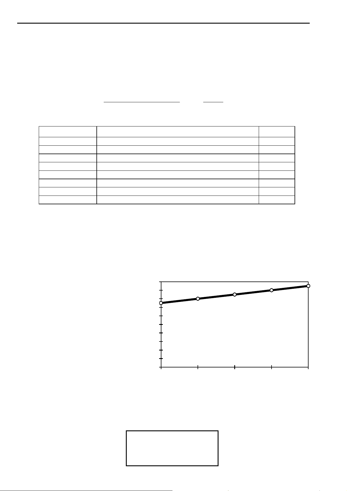
Instruction Manual ITEM TE700 TECNA S.p.A.
Example:
The welding tests proved that: the electrode life corresponds to 2000 welding spots; that with
new electrodes the required current is 15 kA; that after 2000 spots the electrodes diameter
increment requires a 19 kA current.
The percent variation is calculated as follows:
15
1519
%26100
Change
rentinitialcurendcurrent
100%
rentinitialcur
Consequently the following parameters are set in the "STEPPER MENU":
PARAMETER PARAMETER DESCRIPTION VALUE
TOOLS N° Identifier of the tool which the stepper module works on 1
STEPPER WELD Parameter adjustment increase, current in the example ON L1
STEPPER TIME Weld time increase OFF
STEPPER THICK. Electrodes thickness decrease OFF
TOTAL STEPS Total number of stepper steps 1
SPOTS 1 Number of spots of first segment 2000
INCREMENT 1-L1 Percentage increase of the first segment relevant to law L1 26 %
INCREMENT 1-L2 Percentage increase of the first segment relevant to law L2 00 %
The welding program must be set in order to carry out the first welding spot, which is with an
adjustment enabling to obtain the necessary current with the starting electrodes diameter:
15 kA.
Now the welding process can begin. Current will vary conforming to the set increment rule.
The graph below shows its pattern.
INITIAL CURRENT = 15 kA
FINAL CURRENT = 19 kA
INCREMENT PERCENT = 26 %
WELDING SPOTS NUMBERS = 2000
CURRENT INCREASE DURING THE PRODUCTION
20
18
16
14
12
10
8
6
4
WELDING CURRENT (kA)
2
0
0 500 1000 1500 2000
NUMBER OF WELDING SPOTS
On having completed the 2000 welding spots, the control unit stops the production cycle and
displays the following message:
STEPPER [164]
END
WARNING ON TOOLS T1
PUSH [///] TO RESET
62/128
Page 63
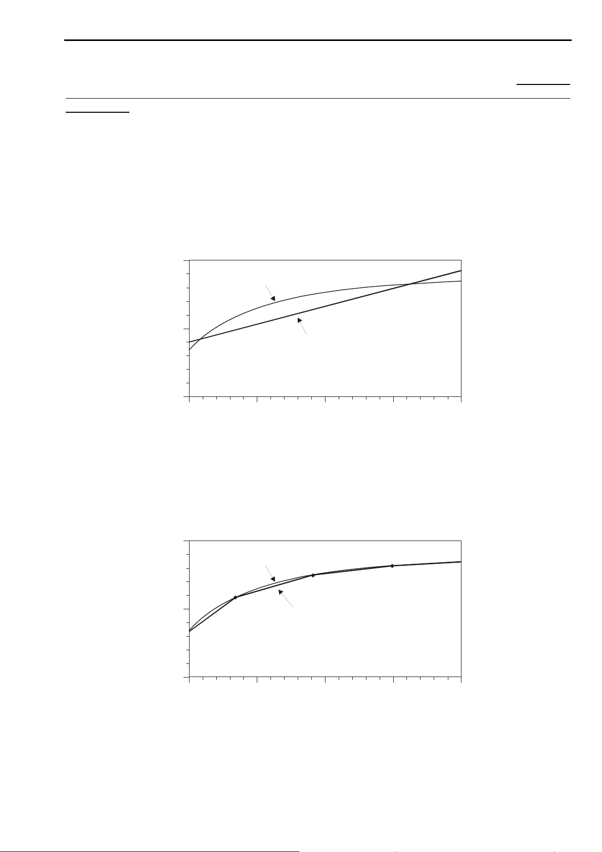
TECNA S.p.A. ITEM TE700 Instruction Manual
Now the operator replaces the electrodes (or restores their original diameter) and clears the
spots counter relevant to the tool whose electrodes were replaced to clear the stepper
calculations.
The TE700 resets the initial work parameters and begins a new stepper phase.
COMPLETE USE OF THE STEPPER FUNCTION (NON-LINEAR INCREMENT CURVE)
It is possible to use the non-linear increment curve function by knowing the real electrodes
consumption only.
In the aforesaid work method, a linear welding current increment is used during the whole life
span of the electrodes. In actual fact the increase of the contact section of the electrode on
the sheet is not linear but has a pattern that is similar to the one shown in the graph below.
IDEAL PATTERN
CURRENT
REAL PATTERN
WITH LINEAR INCREMENT
NUMBER OF WELDING SPOTS
As such the use of the linear increment is an approximation which nonetheless permits to
achieve good results in most applications. However when the operator wishes to achieve
utmost constancy during work conditions, a non-linear increment curve can be set that is
described by defining a certain number of segments.
This type of adjustment requires an adequate knowledge on how electrodes wear and on the
parameters required during their life. Consequently many welding spot tests are necessary for
assessing the work conditions in different moments of the electrodes' life.
IDEAL PATTERN
REAL PATTERN
CURRENT
WITH SET INCREMENT
CURVE
NUMBER OF WELDING S POT S
The increment curve is set by assessing a certain number of linear segments. The number of
welding spots and the desired increment are assessed for each segment.
63/128
Page 64
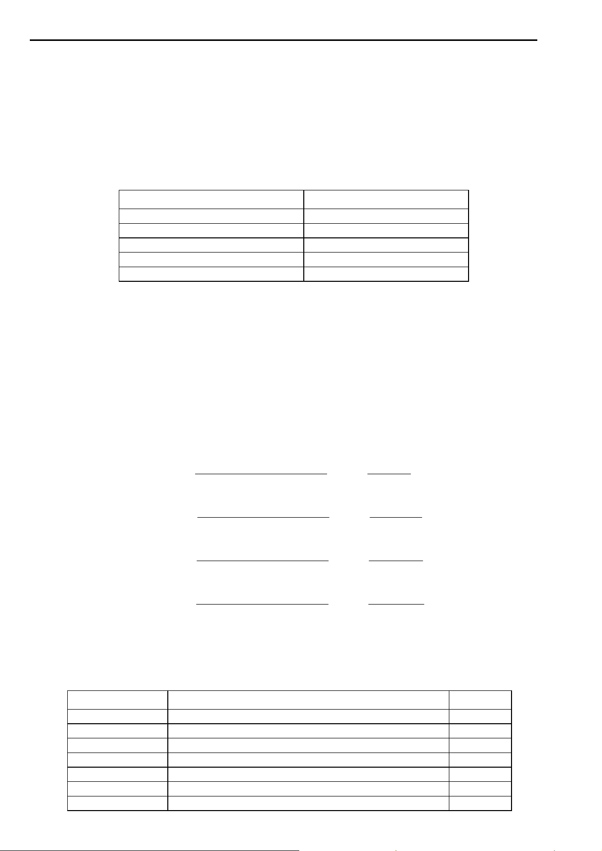
Instruction Manual ITEM TE700 TECNA S.p.A.
r
The N.TOTAL STEPS parameter determines the number of segments to be entered in the
stepper curve. Enter the number of welds that make up the segment in parameters SPOTS
1,2… and enter the relevant percentage increase to be carried out in parameter INCREMENT
1-L1,2-L1….
The programming procedure is outlined in the STEPPER MENU paragraph.
Example:
Welding tests have determined that the electrode life corresponds to 4000 welding spots, and
that the following currents values are necessary at different moments of the electrodes life
WELDING SPOTS EXECUTED NECESSARY CURRENT
0 (initial electrode diameter) 15 kA
700 17.8 kA
1800 19.5 kA
3000 20.2 kA
4000 (final electrode diameter) 20.7 kA
Therefore calculate the duration (in number of welding spots) and the percent increment of
each segment.
Please, notice that the percent increment must always be calculated referring to the beginning
of the considered segment.
spots 700=0-700=1segment ofDuration
spots 1100=700-1800=2segment ofDuration
spots 1200=1800-3000=3segment ofDuration
spots 1000=3000-4000=4segment ofDuration
15
158.17
8.17
5.19
220
.
rentinitialcurendcurrent
segmentChange
1001 %
rentinitialcur
rentinitialcurendcurrent
segmentChange
1002 %
rentinitialcur
rentinitialcurendcurrent
segmentChange
1003 %
rentinitialcur
4 segment % Change 3100
rentinitialcurendcurrent
100
rentinitialcu
The following parameters are consequently set in the STEPPER MENU:
PARAMETER PARAMETER DESCRIPTION VALUE
TOOLS N° Identifier of the tool on which the stepper module works 1
STEPPER WELD Parameter adjustment increase, current in the example ON L1
STEPPER TIME Weld time increase OFF
STEPPER THICK. Electrodes thickness decrease OFF
N.TOTAL STEPS Total number of stepper steps 4
SPOTS 1 Number of spots of first segment 700
INCREMENT 1-L1 Percentage increase of the first segment relevant to law L1 19 %
%19100
8.175.19
%10100
5.192.20
%4100
220820
..
%
64/128
Page 65
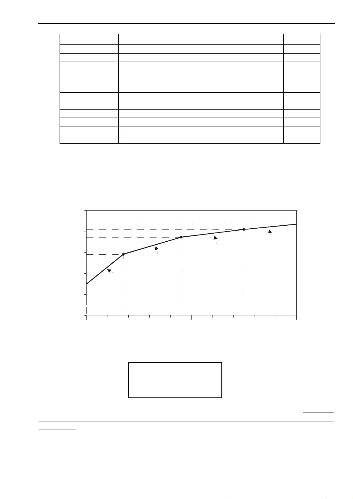
TECNA S.p.A. ITEM TE700 Instruction Manual
)
PARAMETER PARAMETER DESCRIPTION VALUE
INCREMENT 1-L2 Percentage increase of the first segment relevant to law L2 00 %
SPOTS 2 Number of spots of second segment 1100
INCREMENT 2-L1 Percentage increase of the second segment relevant to law
L1
INCREMENT 2-L2 Percentage increase of the second segment relevant to law
L2
SPOTS 3 Number of spots of third segment 1200
INCREMENT 3-L1 Percentage increase of the third segment relevant to law L1 4 %
INCREMENT 3-L2 Percentage increase of the third segment relevant to law L2 00 %
SPOTS 4 Number of spots of fourth segment 1000
INCREMENT 4-L1 Percentage increase of the fourth segment relevant to law L1 3 %
INCREMENT 4-L2 Percentage increase of the fourth segment relevant to law L2 00 %
The welding program must be set in order to carry out the first welding spot, which is with an
adjustment enabling to obtain the necessary current with the starting electrodes diameter:
15 kA.
Now the welding process can begin. Current will change according to the programmed
increment rule. The graph below shows its pattern.
22
10 %
00 %
21
20
19
17.8 kA
18
17
16
CURRENT (kA
15
14
13
19.5 kA
SEGMENT 1
700
20.2 kA
SEGMENT 2
20.7 kA
SEGMENT 3
1800
NUMBER OF WELDING SPOTS
SEGMENT 4
3000
40003000200010000
On having completed the 4000 welding spots, the control unit stops the production cycle and
displays the following message:
STEPPER [164]
END
WARNING ON TOOLS T1
PUSH [///] TO RESET
Now the operator replaces the electrodes (or restores their original diameter) and clears the
spots counter relevant to the tool the electrodes of which were replaced to clear the stepper
calculations.
The TE700 resets the initial work parameters and begins a new stepper phase.
65/128
Page 66
Instruction Manual ITEM TE700 TECNA S.p.A.
2.12 - FEATURES TE700
-TE700 VER. 1.13- SETUP MENU
STEPPER MENU
>FEATURES TE700
The TE700 installation menu contains the parameters that describe the complexity and the
typology of the welder on which the control unit works. Access to said menu is protected by
an access code due the importance of these parameters.
ENTER ACCESS CODE
FEATURES MENU
- - - - -
If the operator is not authorized to enter this menu and does not know the access code, the
following message is displayed:
WRONG CODE
TRY AGAIN !
The parameters can be edited only after having typed in the access code.
FEATURES TE700
>SERIAL COM. OFF
NET ADDRESS 01
OUT LOCK/END END
Keep in mind that only skilled personnel are permitted to edit the following
parameters to prevent damage to people or equipment.
PARAMETER PARAMETER DESCRIPTION RANGE VALUE
SERIAL COM. Serial communication 232 – 485 – OFF
NET ADDRESS Network address 01 – 31
OUT LOCK/END Output function END – LOCK
LOW FORCE SQ. Low force squeeze ON - OFF
FORGE Forging ON – OFF
PROP. VALVE Proportional valve ON - OFF
PRESSURE RATIO Proportional ratio 0.1 – 2.0
AUTORETAIN Start Autoretain ON – OFF
START 1-2 NC Operation of NC inputs OFF – RIC 7-8 – ON
BIC 1-2 NC Operation of NC inputs OFF – RIC 5-6 – ON
SEAM WELD MODE Spots / seams ON – OFF
CASCADE MODE Electric cascade function ON – OFF
WELD – NO WELD Operation of weld - no weld external
input
DSP UPG PRESS Command to update inverter SW <+>
INT – EXT – BOTH
66/128
Page 67
TECNA S.p.A. ITEM TE700 Instruction Manual
THICK SENSOR Enabling of the parameters relevant to
the thick sensor (position sensor)
STEPPER TIME Enabling of the stepper functionality on
the welding time
SERIAL COM.
The operator may choose whether to activate the serial data transmission port and how it is to
be used, connect a printer (232) or connect the control unit to a data supervision network
(485), or not to use this option (OFF).
NET ADDRESS
This parameter indicates the identifying address of the control unit when connected in the
network, activating the aforesaid option.
OUT LOCK/END
This parameter is used to indicate the time for activation of the corresponding output, interlock
(LOCK) or end of cycle (END).
LOW FORCE SQ.
This parameter is used for enabling the low-pressure squeeze function for pneumatic circuit
welders that are equipped with this function. Its enabling adds the SQUEEZE parameter to
the welding program.
FORGE
This parameter is used for enabling the forging for pneumatic circuit welders that are
equipped with this function. Its enabling adds the FORGE DELAY parameter to the work
program.
PROP. VALVE
This parameter is used for enabling the use of a proportional valve for pneumatic circuit
welders that are equipped with this function. Its enabling adds the PRESSURE parameter to
the work program.
If the FORGE parameter is enabled too, then the FORG.PRESS. parameter is added to the
work program.
PRESSURE RATIO
This parameter can be used to select the optimum bar/Volt ratio for the type of proportional
solenoid valve that is to be employed. It works only if the PROP. VALVE parameter is
enabled.
Further pieces of information are described in the paragraph INTERFACE FOR
PROPORTIONAL VALVE.
AUTORETAIN
This parameter allows disabling the AUTORETAIN cycle start signal.
On setting the parameter on the OFF value, the working cycle is stopped the moment the
cycle start signal is disabled and does not complete the welding time. This occurs even if the
welding current is in its flowing phase.
The welding time is always completed whenever the value is set to ON.
This function is specifically to be used when the machine works with mechanical devices
instead of pneumatic ones.
ON – OFF
ON – OFF
67/128
Page 68

Instruction Manual ITEM TE700 TECNA S.p.A.
If the control unit is in seam weld mode with autoretain deactivated, its activation implies the
automatic deactivation of the seam weld mode and automatic commutation of the unit to
SPOT mode.
START 1-2 NC
When this parameter is set to ON it enables the normally closed inputs of the cycle start
signals. This allows the starting of the welding cycle only in the presence of the double
exchange contact, normally open that closes and normally closed that opens.
When set to OFF, the control unit ignores the status of the two signals and the starting of the
welding only depends on the status of the NO inputs.
If set to RIC 7-8, the two NO inputs become program recalls from a functional point of view so
as to extend the number of recallable programs directly through the inputs.
BIC 1-2 NC
When this parameter is set to ON it enables the normally closed inputs of the cycle start
signals. This allows the starting of the welding cycle only in the presence of the double
exchange contact, normally open that closes and normally closed that opens.
When set to OFF, the control unit ignores the status of the two signals and the starting of the
welding only depends on the status of the NO inputs.
If set to RIC 5-6, the two NO inputs become program recalls so as to extend the number of
recallable programs directly through the inputs.
SEAM WELD MODE
This parameter is used to enable the function that adapts the control unit to seam welder
specifications. The activation of the seam weld mode automatically deactivates the autoretain.
Further information is supplied in the SEAM WELD MODE paragraph.
CASCADE MODE
This parameter allows reversing the output signal of the end cycle (END), that is to say from
normally open contact to normally closed contact, to allow putting more control units in
cascade.
Check the proper paragraph for further information.
WELD – NO WELD
When the optional board code 50200 is installed, this parameter allows the operator to select
the priority of the weld-no-weld control.
When the parameter is set to INT, the running of the external WELD-NO WELD line is
deactivated whilst the button on the TE700 control unit remains enabled.
When the parameter is set to EXT, the running of the external WELD-NO WELD line on board
code 50200 is active whilst the button on the front panel of the TE700 control unit is disabled.
When the parameter is set to BOTH, both WELD-NO WELD controls are enabled: the one on
the TE700 front panel and the external control line on the board code 50200. The two controls
are in series therefore to switch the unit to NO WELD mode, simply set only one of the two
controls to NO WELD mode whilst in order to switch the unit to WELD mode both controls
must be switched to WELD mode.
DSP UPG PRESS
If key <+> is pressed when this parameter is selected, the operator can remotely activate the
software upgrade procedure inside the inverter unit. The spot welder must not be off during
the upgrade procedure. Any other operation during the upgrade procedure is prohibited and
welds may not be carried out. In order to resume the running of the spot welder after the
upgrade procedure, it must be turned off and then back on again once the procedure is
finished.
68/128
Page 69

TECNA S.p.A. ITEM TE700 Instruction Manual
THICK SENSOR
This parameter enables the THICKNESS SENSE menu for parameterizing eventual position
sensors connected to the control unit. Also, by means of a stepper law, it enables the
possibility of compensating the electrode’s wear according to the initial quote.
STEPPER TIME
This parameter allows enabling the welding time stepper law inside the stepper menu. This
law is enabled either independently or associated with a current stepper value.
69/128
Page 70
Instruction Manual ITEM TE700 TECNA S.p.A.
2.13 - FEATURES INVERTER
-TE700 VER. 1.13- STEPPER MENU
FEATURES TE700
>FEATURES INVERTER
The inverter installation menu contains the parameters that describe the complexity and the
typology of the welder on which the control unit works. Access to said menu is protected by
an access code due the importance of these parameters.
ENTER ACCESS CODE
FEATURES MENU
- - - - -
If the operator is not authorized to enter this menu and does not know the access code, the
following message is displayed:
WRONG CODE
TRY AGAIN !
The parameters can be edited only after having typed in the access code.
FEATURES INVERTER
>INVERTER SIZE 0250A
TA TURNS 500
FREQUENCY 1000Hz
Keep in mind that only skilled personnel are permitted to edit the following
parameters to prevent damage to people or equipment.
PARAMETER PARAMETER DESCRIPTION RANGE VALUE
INVERTER SIZE Max current supplied by the inverter 50 A – 4000 A
TA TURNS Number of sensor turns primary current 500 – 2000
FREQUENCY Inverter operating frequency 1000–2000–3000–4000 Hz
CURRENT LOOP Current adjustment loop ROG – TA
EXT.REF.INPUT Analogue input for current profile OFF – ON
VE INPUT Electrodes voltage gauge OFF – ON
TH TR. PRIM. Transformer primary thermal current 0 – 60000 A
TH TR TIME Transformer thermal time constant 0.0 – 6000.0 S
TH TR DIODE Type of diodes installed in the welding
transformer
ROGOWSKY TEST Check for Rogowsky coil integrity OFF – ON
N° WELDING TRAFO Number of welding transformers or tools
used.
TURNS TR.1 Transformer 1 turns ratio 1 – 200
OFF – 2*56DN – 4*56DN –
8*56DN – 2*65DN – 4*65DN
– 8*65DN
1 – 4
70/128
Page 71
TECNA S.p.A. ITEM TE700 Instruction Manual
I MAX TR.1 Max supplied current 2.00 – 200.00 KA
TURNS TR.2 Transformer 2 turns ratio 1 – 200
I MAX TR.2 Max supplied current 2.00 – 200.00 KA
TURNS TR.3 Transformer 3 turns ratio 1 – 200
I MAX TR.3 Max supplied current 2.00 – 200.00 KA
TURNS TR.4 Transformer 4 turns ratio 1 – 200
I MAX TR.4 Max supplied current 2.00 – 200.00 KA
It is important to keep in mind that after having modified the following
parameters the memory of the TE700 control unit must always be reset.
INVERTER SIZE
Indicates the max current that the inverter can supply at output. If a wrong value is set, this
could damage the inverter and/or the welding transformer.
TA TURNS
Indicates the turns ratio of the current transducer installed inside the inverter. If a wrong value
is set, this could lead to a wrong adjustment of the welding current.
FREQUENCY
This parameter sets the frequency at which the power semiconductors are switched. This
control unit can work at 1000 Hz, 2000 Hz, 3000 Hz and 4000 Hz. The selected operating
frequency must be adapted to the welding transformer used otherwise it might be damaged. If
an operating frequency higher than 1000 Hz is selected, it will not be possible to activate the
thermal limit switches relevant to the welding transformer and/or the diodes. If the thermal
limit switches relevant to the welding transformer and/or the diodes were previously activated,
when a work frequency higher than 1000Hz is selected, the following message is displayed:
THERMAL LIMIT SW OFF
<+> OK <-> CANCEL
If key <-> is pressed, the previously set thermal limit switches will remain energized and the
operating frequency of the inverter remains at 1000 Hz. If key <+> is pressed, the thermal
limit switches relevant to diodes and welding transformer will be disabled automatically and
the operator will be able to use an inverter operating frequency higher than 1000 HZ.
CURRENT LOOP
This parameter allows the operator to choose which current transducer should be used in the
adjustment loop. If set to ROG, the Rogowsky coil installed on the secondary circuit of the
machine is used to adjust the current. If set to TA, a current sensor inside the inverter and
installed on the primary of the welding transformer is used for the adjustment.
The best performance of the current adjustment loop is achieved by selecting ROG and
installing the Rogowsky coil on the secondary circuit of the spot welder.
71/128
Page 72

Instruction Manual ITEM TE700 TECNA S.p.A.
The adjustment, made through TA, is to be used when a Rogowsky coil cannot be installed on
the secondary circuit of the spot welder or if set to seam weld mode.
If the seam weld mode is selected when Rogowsky has been selected as current sensor, a
continuous weld cannot be carried out but the minimum COLD 2 TIME will be 8 mS. If TA has
been selected as current sensor, the COLD 2 TIME may be set to 0mS and a continuous
weld may be carried out without any interruptions.
EXT.REF.INPUT
This parameter allows the operator to enable an analogue input in the inverter unit with
dynamics 0 – 10V by means of which a current profile may be supplied to the welder to be
followed through a variable voltage applied at the appropriate input.
VE INPUT
This parameter allows the gauging of the voltage at the electrodes but, before doing so, be
sure that the wires that carry out the measurement are properly installed.
TH TR. PRIM
This parameter allows the setting of the primary thermal current of the welding transformer. If
the value is equal to zero or the value of the TH TR. TIME parameter equals zero, the limit
switch at the thermal current of the welding transformer is deactivated. This function may be
activated only when the inverter unit has been set with an operating frequency of 1000 Hz. If
the operating frequency is greater than 1000 Hz the following message is displayed:
FAIL INIT THERMAL
LIM
CHECK PARAM. CONFIG.
This parameter may be modified only after having set an operating frequency of 1000 Hz. The
function cannot be activated if an operating frequency greater than 1000Hz is set.
TH TR. TIME
This parameter allows the setting of the thermal time constant of the welding transformer. If
the value is equal to zero or the value of the TH TR. PRIM parameter equals zero, the limit
switch at the thermal current of the welding transformer is deactivated. This function may be
activated only when the inverter unit has been set to an operating frequency of 1000 Hz. If the
operating frequency is greater than 1000 Hz the following message is displayed:
FAIL INIT THERMAL
LIM
CHECK PARAM. CONFIG.
The parameter may be modified only after having set an operating frequency of 1000 Hz.
72/128
Page 73

TECNA S.p.A. ITEM TE700 Instruction Manual
TH TR. DIODE
This parameter allows the setting of the type of rectifiers installed on the secondary circuit of
the welding transformer. This function may be activated only if the operating frequency of the
inverter equals 1000 Hz. If operating frequencies are greater, the parameter cannot be
modified and the following message is displayed:
FAIL INIT THERMAL
LIM
CHECK PARAM. CONFIG.
ROGOWSKY TEST
It enables the check for the integrity both of the Rogowsky coil and the cable that connects it
to the inverter unit. If the function is activated, the inverter periodically checks that the circuit
of the current sensor is neither open nor short circuited. If a fault occurs, welding is inhibited
and the condition is signalled on the TE700 display. The activation of the Rogowsky test
function leads to a decrease in the max number of spots that the inverter may carry out in one
minute.
N° WELDING TRAFO
This parameter sets the number of welding transformers used with the inverter or alternatively
the number of the different welding tools used. If the operator intends using different tools for
the welding operations but only one welding transformer, set the required number of tools and
set the same turns and max current value, in the following parameters, for all the welding
transformers. If the operator intends using different welding transformers, each transformer
should be characterized by its turns ratio and by the max secondary current that can be
supplied. If the operator uses different welding transformers the Rogowsky integrity test must
not be enabled. If the operator uses more than one transformer or welding tool, the thermal
limit switches cannot be activated at the primary thermal current and at the diodes thermal
switch.
If the operator wishes to use different tools for alternating welds on a single welding
transformer, he/she must set the parameter equal to the number of welding tools used and in
any case the max number is four. Moreover, the operator must set the turns ratio of the
welding transformers to an identical value for all the transformers and equivalent to the turns
ratio of the transformer installed on the spot welder. Even the max supplied current values
from each transformer must all be set to the same value of the max current that is supplied by
the transformer installed on the spot welder.
TURNS TR.1
It sets the number of turns of welding transformer 1.
IMAX TR.1
It sets the max current that may be supplied by welding transformer 1.
TURNS TR.2
It sets the number of turns of welding transformer 2.
IMAX TR.2
It sets the max current that may be supplied by welding transformer 2.
73/128
Page 74

Instruction Manual ITEM TE700 TECNA S.p.A.
TURNS TR.3
It sets the number of turns of welding transformer 3.
IMAX TR.3
It sets the max current that may be supplied by welding transformer 3.
TURNS TR.4
It sets the number of turns of welding transformer 4.
IMAX TR.4
It sets the max current that may be supplied by welding transformer 4.
74/128
Page 75
TECNA S.p.A. ITEM TE700 Instruction Manual
2.14 - PROGRAMS COPY
-TE700 VER. 1.13- FEATURES TE700
FEATURES INVERTER
>PROGRAM COPY
This menu is used for copying the values of the parameters of a program to other programs
without having to set one parameter at a time (to make programming quicker).
PROGRAM COPY
>SOURCE PROGRAM. 003
COPY FROM PRG. 006
TO PROGRAM 010
After having selected the source program and the programs which it is to be saved in, simply
press the ¼ key and a request will appear asking either to continue and copy or cancel the
operation.
COPY PROGRAM?
<+> OK <-> CANCEL
In order to copy, simply press key <+> and the following screen is displayed. The bar shows
the copying progress state.
PROGRAM COPY WAIT…
▌▌▌▌▌▌▌▌▌
When the copying procedure is finished, the main programming screen is displayed.
-TE700 VER. 1.09- FEATURES TE700
FEATURES INVERTER
>PROGRAM COPY
PROGRAM COPY MENU PARAMETERS TABLE
PARAMETER PARAMETER DESCRIPTION RANGE VALUE
SOURCE PROGRAM Source program 001 – 300
COPY FROM PRG Start copy/target program 001 – 300
TO PROGRAM Copy end program 001 – 300
75/128
Page 76

Instruction Manual ITEM TE700 TECNA S.p.A.
SOURCE PROGRAM
This program indicates the number of the program to be copied to other programs. The value
of this parameter may range from 001 to 250.
COPY FROM PRG
This program indicates the first program which the source program is copied into. The value
of this parameter may range from 001 to 250.
TO PROGRAM
This program indicates the last program which to copy the source program into. The value of
this parameter may range from 001 to 250.
76/128
Page 77
TECNA S.p.A. ITEM TE700 Instruction Manual
2.15 – CHECK INPUT – DIAGNOSTIC TE700
-TE700 VER. 1.13- FEATURES INVERTER
PROGRAM COPY
>DIAGNOSTIC TE700
This menu displays the status of the inputs of the TE700 weld control unit. It is used to check
the working efficiency of the external devices, connected to the TE700 control unit, required
for using the welder.
DIAGNOSTIC TE700
>START 1 PRG OFF
START1 NC-RIC7 OFF
AUX OFF
The following inputs are mentioned in the list which may be scrolled by means of the and
keys.
PARAMETER PARAMETER DESCRIPTION VALUE
START 1 PRG It indicates the status of the cycle start signal ON – OFF
START1 NC-RIC7 It indicates the status of cycle start NC signal or RIC7 ON – OFF
AUX It indicates the status of the auxiliary signal ON – OFF
AUX 3 It indicates the status of the auxiliary 3 signal ON – OFF
DOUBLE STROKE It indicates the status of the double stroke signal ON – OFF
START 2 PRG It indicates the status of the cycle 2 start signal ON – OFF
START2 NC-RIC8 It indicates the status of cycle start NC signal or RIC8 ON – OFF
TERM/FLUX It indicates the status of the thermostat signal ON – OFF
PRG.RECALL 1 It indicates the status of the recall 1 signal ON – OFF
PRG.RECALL 2 It indicates the status of the recall 2 signal ON – OFF
PRG.RECALL 3 It indicates the status of the recall 3 signal ON – OFF
PRG.RECALL 4 It indicates the status of the recall 4 signal ON – OFF
INVERTER READY It indicates the status of the READY signal from the inverter unit ON – OFF
SAFETY START 1 It indicates the status of the signal of safety start 1 ON – OFF
BIC1 NC-RIC5 It indicates the status of the NC signal of two-hand control button 1 or
RIC5
SAFETY START 2 It indicates the status of the signal of safety start 2 ON – OFF
BIC2 NC-RIC6 It indicates the status of the NC signal of two-hand control button 2 or
RIC6
ON – OFF
ON – OFF
(When Code 50200 option is present)
RESET DRESS It indicates the status of the accomplished electrodes dressing signal ON – OFF
WELD / NO WELD It indicates the status of the external weld / no weld signal ON – OFF
RESET ERROR It indicates the status of the errors clear signal ON – OFF
RESET ELECTRODE It indicates the status of the accomplished electrodes change signal ON – OFF
The input status is represented as enabled (closed input with COM1) by means of the wording
ON, while it is represented as disabled by means of the wording OFF.
77/128
Page 78
Instruction Manual ITEM TE700 TECNA S.p.A.
2.16 – CHECK INPUT – DIAGNOSTIC INVERTER
-TE700 VER. 1.09- PROGRAM COPY
DIAGNOSTIC TE700
>DIAGNOSTIC INV.
This menu displays the status of the inputs and outputs of the inverter unit connected to the
TE700. It is used to check the working efficiency of the inverter unit.
DIAGNOSTIC INV.
>VERSION INV. 2.02
RIC 1 OFF
RIC 2 OFF
The following inputs are mentioned in the list which may be scrolled by means of the
and
keys.
PARAMETER PARAMETER DESCRIPTION VALUE
VERSION INV. It indicates the software version installed in the inverter. X.XX
RIC 1 It indicates the status of the signal relative to RIC 1 inside the inverter. ON – OFF
RIC 2 It indicates the status of the signal relative to RIC 2 inside the inverter. ON – OFF
RIC 3 It indicates the status of the signal relative to RIC 3 inside the inverter. ON – OFF
RIC 4 It indicates the status of the signal relative to RIC 4 inside the inverter. ON – OFF
TERM It indicates the status of the signal relative to thermostat wired on the
inverter.
DRIVER It indicates a power semiconductor driver fault. NO ERR –
EMERGENCY It indicates the status of the signal relevant to the emergency chain on
the inverter.
WELD NO WELD It indicates the status of the weld-no weld signal inside the inverter. ON – OFF
TRIGGER It indicates the status of the welding start signal inside the inverter. ON – OFF
RIC 5 / WELD 2 It indicates the status of signal RIC 5 or SEAM WELD. 2 inside the
inverter.
OUT EV WATER It indicates the status of the inverter output that controls the EV for the
cooling circuit water.
OUT READY It indicates the status of inverter output for the READY signal
transmitted to the TE700 control unit.
OUT LOCK It indicates the status of the LOCK output of the inverter. ON – OFF
OUT WRONG It indicates the status of the WRONG output of the inverter. ON – OFF
VER. DRIVER It indicates the software version installed inside the board that checks
for the capacitors' charged condition.
CAPACITOR VOLT It indicates the voltage present on the bank of capacitors inside the
inverter.
Warning: this measurement is indicative and should not be used
as a reference when operating in the inverter unit.
BOARD TEMP. It indicates the room temperature on the inverter unit. XX.X°C
SINK TEMP. It indicates the temperature of the dissipater on which the power
semiconductors are installed.
THERMAL LEVEL It indicates the use percentage of the inverter in case the thermal limit
switches tripped relative to the primary of the weld transformer and/or
the diodes of the secondary rectifier.
SCR DRV STATUS Alphanumeric code that indicates the operating status of the board
that checks for the capacitors' charged condition.
INV. SERIAL Inverter unit serial number. XXXXX
78/128
ON – OFF
ERR
ON – OFF
ON – OFF
ON – OFF
ON – OFF
XX.X
000V
XX.X°C
XXX%
XX
Page 79
TECNA S.p.A. ITEM TE700 Instruction Manual
2.17 - PROG. SEQUENCE
-TE700 VER. 1.13- DIAGNOSTIC TE700
DIAGNOSTIC INV.
>PROG. SEQUENCE
This menu includes the parameters required for activating the programs sequences
operations. In this working mode the weld control unit commands the welder to perform a
series of spots, deciding automatically the work program for each spot and the spots order
without having to make an external selection of the program.
PROG. SEQUENCE
>STEP 1 PRG. 003
STEP 1 WELDS 07
STEP 2 PRG. 012
PROGRAM SEQUENCES MENU PARAMETERS TABLE
PARAMETER PARAMETER DESCRIPTION RANGE VALUE
STEP 1 PRG. Program to be carried out in the step 1 000 – 250
STEP 1 WELDS Number of spots to be carried out with step 1 01 – 25
STEP 2 PRG. Program to be carried out in the step 2 001 – 250
STEP 2 WELDS Number of spots to be carried out with step 2 00 – 25
STEP 3 PRG. Program to be carried out in the step 3 001 – 250
STEP 3 WELDS Number of spots to be carried out with step 3 00 – 25
STEP 4 PRG. Program to be carried out in the step 4 001 – 250
STEP 4 WELDS Number of spots to be carried out with step 4 00 – 25
STEP 5 PRG. Program to be carried out in the step 5 001 – 250
STEP 5 WELDS Number of spots to be carried out with step 5 00 – 25
STEP 1 PRG.
This parameter indicates the number of the program that the welder must carry out, and is
coupled with the STEP 1 WELDS parameter.
When this parameter is set to zero, the programs sequence is disabled.
STEP 1 WELDS
The value of this parameter indicates the number of welds to be carried out with the program
matched to the same step.
STEP 2 PRG.
This parameter indicates the program number that the welder has to carry out and is always
coupled with the STEP 2 WELDS parameter.
STEP 2 WELDS
The value of this parameter indicates the number of welds to be carried out with the program
matched to the same step.
STEP 3 PRG.
This parameter indicates the program number that the welder has to carry out and is always
coupled with the STEP 3 WELDS parameter.
79/128
Page 80
Instruction Manual ITEM TE700 TECNA S.p.A.
STEP 3 WELDS
The value of this parameter indicates the number of welds to be carried out with the program
matched to the same step.
STEP 4 PRG.
This parameter indicates the program number that the welder has to carry out and is always
coupled with the STEP 4 WELDS parameter.
STEP 4 WELDS
The value of this parameter indicates the number of welds to be carried out with the program
matched to the same step.
STEP 5 PRG.
This parameter indicates the program number that the welder has to carry out and is always
coupled with the STEP 5 WELDS parameter.
STEP 5 WELDS
The value of this parameter indicates the number of welds to be carried out with the program
matched to the same step.
The weld spots may be carried out after having activated this mode and having set the
parameters of the PROGRAM SEQUENCES menu as outlined above. Switch the key to
WORK position on the display to view the data of the sequences as shown in the figure
below.
WELD N.008 TOTAL 013
PROG N.003 RMS 10.45
TIME 10.0 SPOT 00050
NEXT 009 NEXTPRG 002
WELD N.008 TOTAL 013
It indicates the progressive number of the last carried out welding spot and the welding spots
total number the sequence is composed of.
PROG. N.003 RMS 10.45
It indicates the program number and the RMS current value of the last welding spot.
TIME 10.0 SPOT 00050
It indicates the welding time of the last carried out program and the spots counter value.
NEXT 009 NEXTPRG 002
It indicates the progressive number of the next spot and the program to be carried out.
SEQUENCE EXAMPLE
Let's take for example the sequence operation after having set the following values in the
parameters.
PARAMETER VALUE
STEP 1 PRG.
STEP 1 WELDS
STEP 2 PRG.
STEP 2 WELDS
STEP 3 PRG.
STEP 3 WELDS
STEP 4 PRG.
STEP 4 WELDS
03
04
07
02
11
06
04
01
80/128
Page 81
TECNA S.p.A. ITEM TE700 Instruction Manual
At each cycle start signal, a welding spot is carried out with the welding program relevant to
the actual step.
In this specific case, as shown by the below scheme, the following welding spots are carried
out in sequence:
4 welds with program 03
2 welds with program 07
6 welds with program 11
1 weld with program 04
WELD 1 2 3 4 5 6 7 8 9 10 11 12 13
STEPS 1 1 1 1 2 2 3 3 3 3 3 3 4
PROG. 03 03 03 03 07 07 11 11 11 11 11 11 04
This working mode typology is usually applied to a manual welder, where the operator carries
the welding spots out always in the same order but with different working parameters. This
working mode prevents the operator from manually changing the program and, therefore,
from diverting his attention away from the piece to be welded, from changing the foot-pedal or
other cycle start device.
However the operator must pay utmost attention during the process not to perform fewer
spots than those programmed, overlapping spots or not in the same order.
However, should any error occur in the sequence work mode, it is possible to repeat either
the last or another welding spot or to go ahead avoiding certain spots. By always turning the
key in RUN position, by means of the key it is possible to increase the welding spots
counter to the following spot or to the desired one, while, by means of the
to go back of one or more positions along the spots to be carried out.
key it is possible
Display data Display data after key
PRG 007- -01
ST 002-010 NXTPR 008
WELD 0200 RMS 002.99
SPOT 02300 r 034.4
PRG 008- -01
ST 003-010 NXTPR 009
WELD 0200 RMS 002.99
SPOT 02300 r 034.4
PRG 008- -01
ST 003-010 NXTPR 009
WELD 0200 RMS 002.99
SPOT 02300 r 034.4
PRG 008- -01
ST 002-010 NXTPR 008
WELD 0200 RMS 002.99
SPOT 02300 r 034.4
81/128
Page 82
Instruction Manual ITEM TE700 TECNA S.p.A.
2.18 – THICKNESS SENSE
The THICKNESS SENSE menu contains the parameters for configuring the linear position
sensors. A max number of 4 different linear position sensors may be connected to the TE700
control unit, one for each welding tool or one for each welding transformer. Access to said
menu is protected by an access code due to the importance of these parameters.
ENTER ACCESS CODE
FEATURES MENU
- - - - -
If the operator is not authorized to enter this menu and does not know the access code, the
following message is displayed:
WRONG CODE
TRY AGAIN !
The parameters can be edited only after having typed in the access code.
THICKNESS SENSE
>LINEAR SENSOR OFF
LINEAR SENSOR N° 1
SENSOR1 S/N_P1:0000
If the position sensors are activated, they initialize every time the control unit is turned on. If
an initialization error occurs it is signalled on the control unit and the sensors are disabled
automatically. The operator must then solve the failed initialization problem, enter the
THICKNESS SENSE menu and re-enable the position sensors manually.
If multiple position sensors connected to different welding transformers are used, it is
essential that when the TE700 control unit is turned on, all the sensors should be connected
to the communication bus so as to be initialized correctly.
PARAMETER PARAMETER DESCRIPTION RANGE VALUE
LINEAR SENSOR Activation – deactivation of linear
sensors
LINEAR SENSOR N° Number of installed linear sensors 1 – 4
SENSOR1 S/N_P1: Part 1 sensor 1 serial n. XXXX
SENSOR1 S/N_P2: Part 2 sensor 1 serial n. XXXX
SENSOR1 ID CAN: ID CAN for sensor 1 100 – 119
DELAY ID. S1 Delay for indentation measurement 0 – 1000 mS
SENSOR2 S/N_P1: Part 1 sensor 2 serial n. XXXX
SENSOR2 S/N_P2: Part 2 sensor 2 serial n. XXXX
SENSOR2 ID CAN: ID CAN for sensor 2 100 – 119
DELAY ID. S2 Delay for indentation measurement 0 – 1000 mS
SENSOR3 S/N_P1: Part 1 sensor 3 serial n. XXXX
SENSOR3 S/N_P2: Part 2 sensor 3 serial n. XXXX
SENSOR3 ID CAN: ID CAN for sensor 3 100 – 119
DELAY ID. S3 Delay for indentation measurement 0 – 1000 mS
SENSOR4 S/N_P1: Part 1 sensor 4 serial n. XXXX
ON – OFF
82/128
Page 83
TECNA S.p.A. ITEM TE700 Instruction Manual
PARAMETER PARAMETER DESCRIPTION RANGE VALUE
SENSOR4 S/N_P2: Part 2 sensor 4 serial n. XXXX
SENSOR4 ID CAN: ID CAN for sensor 4 100 – 119
DELAY ID. S4 Delay for indentation measurement 0 – 1000 mS
LINEAR SENSOR
It activates or deactivates the use of the linear position sensors. If a sensor initialization error
occurs, it automatically commutates to OFF and the error condition is signalled on the TE700
display. Sensor identification parameters are not deleted. The enabling of the position sensors
makes available the measurements relevant to the initial thickness of the sheets to be welded
and to the electrode penetration at the end of the welding procedure and relevant limits.
LINEAR SENSOR N°
It indicates the number of sensors installed on the machine. If multiple sensors are installed,
the choice of which one to use to carry out the measurement depends on the number of the
welding tool selected for the currently called weld program. For example, if 3 different welding
tools are enabled with 3 associated position sensors and the operator carries out a weld with
a program in which tool number 2 was selected, linear sensor number 2 will be used to
measure the coordinates.
SENSOR1 S/N_P1:
This parameter contains the first part of the serial number of linear sensor 1. The serial
number can be read on the sensor body.
SENSOR1 S/N_P2:
This parameter contains the second part of the serial number of linear sensor 1. The serial
number can be read on the sensor body.
SENSOR1 ID CAN:
This parameter allows the setting of the sensor identifier in the CAN network. In order to work
efficiently, the sensors present inside the CAN network must have univocal identifiers.
DELAY ID. S1
This parameter specifies the delay, in mS, that the system must wait after having finished the
welding current passage in order to measure the coordinate with which to obtain the electrode
penetration value during the welding operation.
SENSOR2 S/N_P1:
This parameter contains the first part of the serial number of linear sensor 2. The serial
number can be read on the sensor body.
SENSOR2 S/N_P2:
This parameter contains the second part of the serial number of linear sensor 2. The serial
number can be read on the sensor body.
83/128
Page 84

Instruction Manual ITEM TE700 TECNA S.p.A.
SENSOR2 ID CAN:
This parameter allows the setting of the sensor identifier in the CAN network. In order to work
efficiently, the sensors present inside the CAN network must have univocal identifiers.
DELAY ID. S2
This parameter specifies the delay, in mS, that the system must wait after having finished the
welding current passage in order to measure the coordinate with which to obtain the electrode
penetration value during the welding operation.
SENSOR3 S/N_P1:
This parameter contains the first part of the serial number of linear sensor 3. The serial
number can be read on the sensor body.
SENSOR3 S/N_P2:
This parameter contains the second part of the serial number of linear sensor 3. The serial
number can be read on the sensor body.
SENSOR3 ID CAN:
This parameter allows the setting of the sensor identifier in the CAN network. In order to work
efficiently, the sensors present inside the CAN network must have univocal identifiers.
DELAY ID. S3
This parameter specifies the delay, in mS, that the system must wait after having finished the
welding current passage in order to measure the coordinate with which to obtain the electrode
penetration value during the welding operation.
SENSOR4 S/N_P1:
This parameter contains the first part of the serial number of linear sensor 4. The serial
number can be read on the sensor body.
SENSOR4 S/N_P2:
This parameter contains the second part of the serial number of linear sensor 4. The serial
number can be read on the sensor body.
SENSOR4 ID CAN:
This parameter allows the setting of the sensor identifier in the CAN network. In order to work
efficiently, the sensors present inside the CAN network must have univocal identifiers.
DELAY ID. S4
This parameter specifies the delay, in mS, that the system must wait after having finished the
welding current passage in order to measure the coordinate with which to obtain the electrode
penetration value during the welding operation.
SETTING THE DELAY PARAMETER ID. SX
During the welding stage which the current passes in, the machine's mechanical structure
might vibrate further to the current's electro-dynamic action. The vibration induced by the
passage of the current does not stop immediately at the end of the current passage but might
require a certain amount of time to stop. Said time depends on the elasticity of the spot
welder structure. The execution of a coordinate measurement during this transient might be
84/128
Page 85

TECNA S.p.A. ITEM TE700 Instruction Manual
altered by the vibrations induced in the structure. As such, a minimum delay must be set,
which depends on each structure, to carry out the coordinate measurements in a static type
situation.
Proceed as follows to determine the minimum wait time before executing the measurement:
1) Configure the linear position sensor for use.
2) Set the DELAY ID. parameter to zero.
3) Set the WELD QUALITY parameter in the SET UP menu equivalent to TONLY (THICKNESS).
4) Set, in the PROGRAM DATA menu, the QUALITY-T parameter to ZERO in
the program used for welding. Carry out a spot in short circuit to zero the
coordinate (electrodes without material in between).
5) Set, in the PROGRAM DATA menu, the QUALITY-T parameter to IDENT in
the program used for welding.
6) Carry out a spot in short circuit, observe the penetration measurement
supplied on the TE700 control unit display at the end of the welding
procedure. If the value remains equal to zero even after several weld spots
this means that the set delay is correct.
7) If the displayed penetration value does not remain constant on carrying
out several welds, return to the THICKNESS SENSE menu and increase
the DELAY ID. parameter relevant to the position sensor used.
8) Repeat a few weld spots as specified in point 6.
85/128
Page 86
Instruction Manual ITEM TE700 TECNA S.p.A.
2.19 – TIP-DRESSINGS
The tip-dressing function is the combination, in just one function, of the current linear stepper
function coupled with the restoring of the electrodes original diameter.
The current stepper function allows compensating the electrodes wear which affects the
welding quality. When the electrodes diameter increases also the contact section between the
electrode and the piece to be welded increases. Consequently, the welding current density
(Ampere/mm2) decreases. In order to compensate this phenomenon, the current adjustment
is gradually increased according to the electrodes diameter increase so to keep a constant
current density.
The restoring of the electrodes original diameter is an operation which is usually carried out
by means of a tool (dresser) allowing restoring the electrodes diameter, which worn out and
increased during the production, to its initial working value.
If the same current adjustment is kept all along the electrodes life or if the electrodes diameter
is never restored to its optimal value, the last carried out welding spots will have a lower
quality than the first ones.
As a rule the electrodes dressing function is used in the presence of an automation that
provides an interface between the weld control unit and the dresser.
After it has been set, the current increment is applied to all the welding programs used.
4 different electrode dressing parameterizations are available and each parameterization is
associated with one of the four different welding tools available. In this way it is possible to
manage the use and dressing of 4 different types of electrodes separately, taking into
consideration, for the current increase, only the spots carried out by every single electrode.
This menu allows programming the tip-dressing number to be carried out during the
electrodes life.
TIP-DRESSING T1
>TOOLS N° 1
DRESSING OFF
DRESSING NUMBER 01
This function is displayed only if the (optional) expansion board, code 50200, is
installed on the control unit.
Before turning on the TE700 control unit with the supplementary
expansion board, code 50200, check that the CLEAR ELECTRODES LIFE
(Pin 52) input is not active.
Otherwise, the 50200 board is not recognized by the control unit.
The activation of this function inhibits the programming of the STEPPER menu. If the stepper
function is active, a message is displayed requesting the operator to confirm the deactivation
of the stepper function for the tool whose electrodes dressing activation is required. The
deactivation of the stepper function does not entail the loss of the parameterization set for the
stepper function.
86/128
Page 87
TECNA S.p.A. ITEM TE700 Instruction Manual
The parameters to be programmed for using the tip-dressing function are the following ones:
PARAMETER PARAMETER DESCRIPTION VALUE
TOOLS N° Selection of the tool in which to parameterize the dressing
function
DRESSING Activation of the dressing function ON – OFF
DRESSING NUMBER Number of tip-dressing to be carried out 00 - 20
SPOT DRESSING Number of welding spots per tip-dressing 001 - 999
DRESSING STEPS Stepper percentage per tip-dressing 01 - 50%
DRESSING ALARM Notice welding spots number 00 – 40
ELECTROD. ALARM Pre-alarm electrodes 01 – 40
DRESSING OFFSET Tip-dressing current compensation 00 – 30%
1 – 4
Each time a value relevant to the tip-dressing is modified, the spots counter is cleared
and the tip-dressing is recalculated from the beginning.
TOOLS N°
This parameter permits selecting on which tool number the electrodes dressing function is to
be parameterized.
DRESSING
This parameter allows the operator to activate or deactivate the dressing function on the tool
specified in the TOOLS N° parameter. Should the stepper function be active in the selected
TOOL, a warning is displayed requesting the operator to deactivate the stepper function.
DRESSING NUMBER
This parameter indicates the number of tip-dressing to be carried out on the electrodes before
these ones become useless.
If this parameter is set to zero, the tip-dressing is not carried out.
SPOT DRESSING
It indicates the number of welding spots per each tip-dressing. The product of this parameter
multiplied by the tip-dressing number (see previous paragraph) indicates the maximum
welding spots number the control unit carries out.
DRESSING STEPS
This parameter indicates the current stepper percentage to be achieved at the end of each
tip-dressing.
DRESSING ALARM
This parameter indicates the number of warning spots during which the DRESSING ALARM
output is enabled, requesting maintenance for the welding electrodes.
If, at the end of the pre-alarm welding spots, the control unit has not received the
accomplished tip-dressing signal, it stops and displays the following message:
DRESSING [165]
CAPS NEED DRESSING
WARNING ON TOOLS T1
PUSH [///] TO RESET
87/128
Page 88
Instruction Manual ITEM TE700 TECNA S.p.A.
In order to restore control unit working efficiency, first of all clear the screen through the
DELETE ERRORS input and then activate the electrodes-dressed signal. If more than one
weld tool was activated the operator can choose which tool to use to dress the electrodes as
follows: if only the external dressing input is activated, to the control unit this means that the
electrode is being dressed on the tool used during the last weld carried out. If the dressing is
to be carried out on a tool other than the one used during the last weld carried out, the
operator uses the RIC1, RIC2 and RIC3 inputs to decide which of the four tools to use to
carry out the dressing as outlined in the following table:
RIC1 RIC2 RIC3 FUNCTION
OFF OFF OFF Dressing of the tool used during the last program used.
ON OFF OFF Dressing of the electrodes of tool 1
OFF ON OFF Dressing of the electrodes of tool 2
ON ON OFF Dressing of the electrodes of tool 3
OFF OFF ON Dressing of the electrodes of tool 4
The required recalls configuration must be set before the activation of the dressing signal and
must be kept steady for the whole duration of the dressing signal activation.
ELECTROD ALARM
This parameter indicates the number of pre-warning spots during which the ELECTRODES
ALARM output is enabled, requesting the replacement of the welding electrodes.
If, at the end of the pre-alarm welding spots, the control unit has not received the signal that
indicates that the electrodes were replaced, it stops and displays the following message:
DRESSING [166]
END CAPS LIFE
WARNING ON TOOLS TI
PUSH [///] O RESET
In order to restore control unit working efficiency, first of all clear the screen through the
DELETE ERRORS input and then activate the electrodes-replaced signal. If more than one
weld tool was activated the operator can choose which tool to use to change the electrodes
as follows: if only the external electrodes-replacement input is activated, to the control unit this
means that the electrode is being replaced on the tool used during the last weld carried out. If
the electrode is to be replaced on a tool other than the one used during the last weld carried
out, the operator uses the RIC1, RIC2 and RIC3 inputs to decide which of the four tools to
use to replace the electrode as outlined in the following table:
RIC1 RIC2 RIC3 FUNCTION
OFF OFF OFF Dressing of the tool used during the last program used.
ON OFF OFF Dressing of the electrodes of tool 1
OFF ON OFF Dressing of the electrodes of tool 2
ON ON OFF Dressing of the electrodes of tool 3
OFF OFF ON Dressing of the electrodes of tool 4
The required recalls configuration must be set before the activation of the electrodes-change
signal and must be kept steady for the whole duration of the electrodes-change signal
activation.
88/128
Page 89
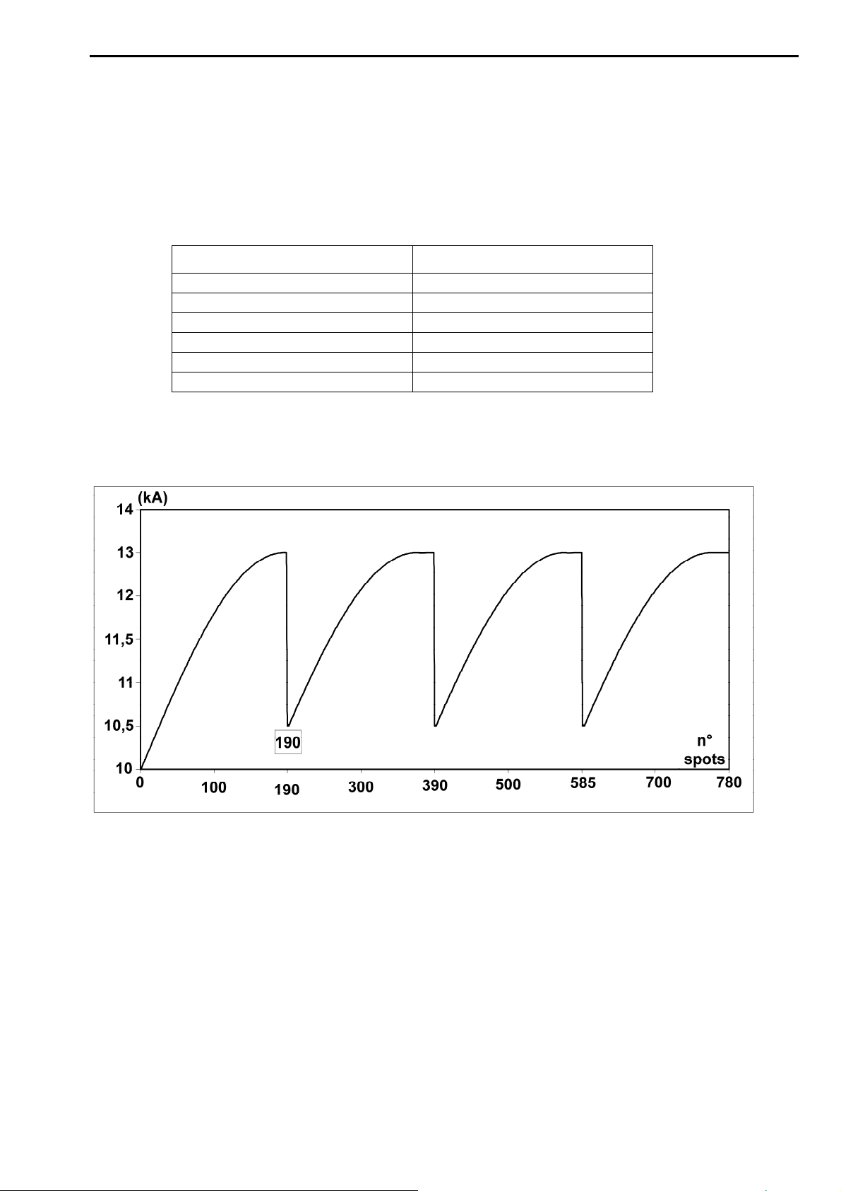
TECNA S.p.A. ITEM TE700 Instruction Manual
DRESSING OFFSET
Use this parameter to increase, in percentage, the starting value of the dressings welding
current after the first one.
EXAMPLE:
The parameters outlined in the table below were set (with a set work program such as, for
example, "WORKING MODE" IK) with an initial current value set to 10KA.
PARAMETER VALUE
DRESSING NUMBER
SPOT DRESSING
DRESSING STEPS
DRESSING ALARM
ELECTRODES ALARM
DRESSING OFFSET
The chart below shows the pattern of how the current increased during the electrodes
dressing run mode.
3
200
30%
20
20
5 %
You may notice that the initial current of the first dressing begins at 10KA whilst a percentage
is added to the starting current value of the next dressing (parameter DRESSING OFFSET).
89/128
Page 90
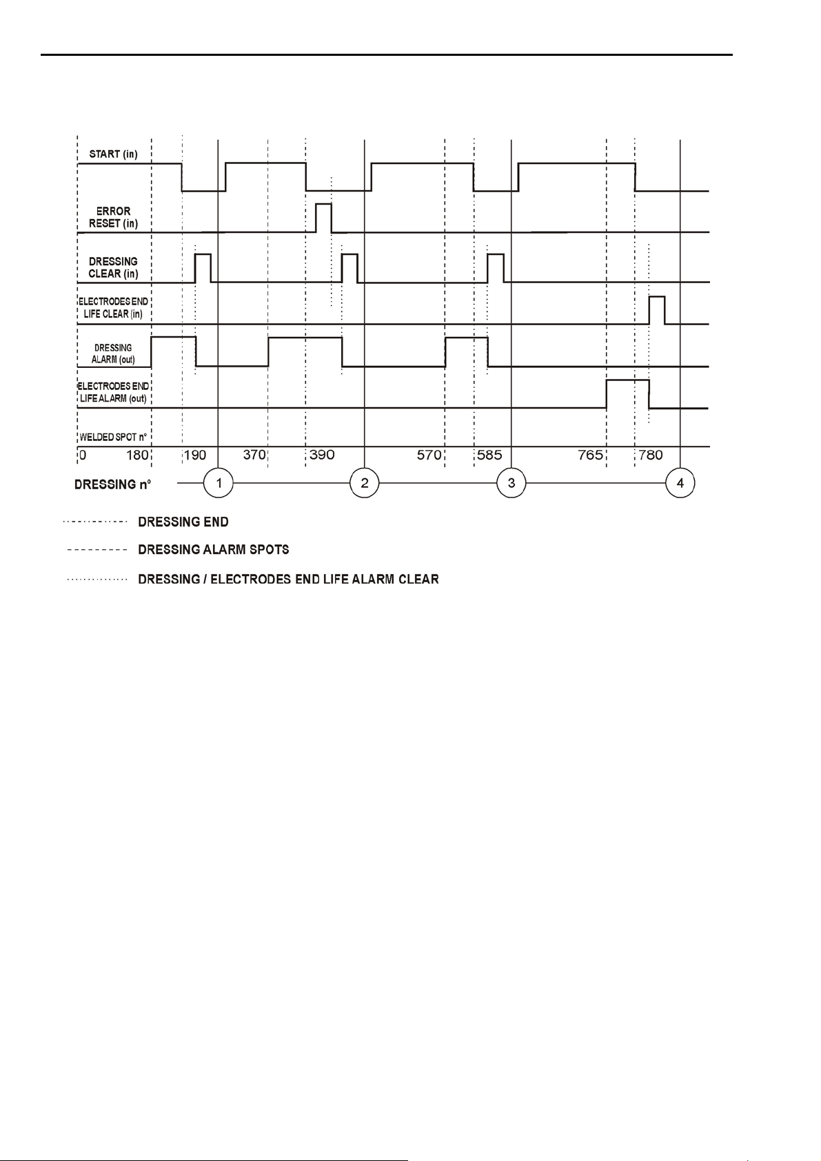
Instruction Manual ITEM TE700 TECNA S.p.A.
The graph below shows the time and modality of the signals used for this WORKING MODE
(with reference to the values outlined in the foregoing table).
From the moment the control unit activates the DRESSING ALARM output it may be reset at
any time by activating the DRESSING RESET input as shown in the foregoing graph for
dressings 1, 3 and 4.
In the example above, the very last spot of the dressing was reached during DRESSING no. 2
without resetting the DRESSING ALARM. In this case the control unit stops and displays the
relevant warning message (ERROR 116). In this case the operator must first delete the
screen from the control unit either through the ERROR RESET input or the CLEAR key, and
then reset the DRESSING ALARM output.
The same is applicable to clear the ELECTRODES END LIFE ALARM output.
When the ELECTRODES END LIFE CLEAR input signal is activated, the control unit resets
the spots counter.
90/128
Page 91

TECNA S.p.A. ITEM TE700 Instruction Manual
CHAPTER 3 – SEAM WELD OPERATING MODE
FEATURES TE700
START 1-2NC OFF
BIC 1-2 NC OFF
>SEAM WELD MODE ON
If the seam weld mode is active on setting the mode, the AUTORETAIN function will be
automatically deactivated at the START inputs. If the operator does not accept the
deactivation of the AUTORETAIN function it will not be possible to activate the seam weld
mode.
This function allows the operator to adapt the control unit to the requirements of a seam
welder. Consequently, welding current is supplied either continuously or via parameter COLD
2 in pulse mode.
On keeping the cycle-start command active, the control unit keeps repeating the time set in
the WELD parameter to prevent the control unit from completing a long weld. time on cutting
off the cycle-start command. We suggest using short weld times.
The welding current is measured indifferently through pulse cycle, WELD and COLD T. 2 time
combination, or through continuous cycle, WELD time only.
In the seam weld mode, the EV3 output is used as a roller-start command instead of being
used for the forging.
On enabling the programming of the WELD 2 parameter, the operator may set not only the
CURRENT parameter but also the CURRENT 2 parameter. During the welding operation it is
possible to commutate between one set current value and the other using the WELD 2 input
present on the INVERTER unit. If the COLD T. 2 parameter is other than zero, each time the
two foregoing current values commutate, the COLD T. 2 is carried out. the COLD T. 2
parameter is equal to zero, the passage between two set current values will take place
instantly.
If Rogowsky was set in the FEATURES INVERTER menu as current sensor for the
adjustment loop, the continuous weld cannot be carried out but only a pulsed weld with a
COLD T. 2 greater than or equal to 8mS.
If TA was set as current sensor for the adjustment loop, it will be possible to carry out even a
continuous weld with COLD T. 2 equal to zero.
According to the type of current adjustment loop, the available weld modes differ as outlined
in the tables below.
During the welding in the SEAM WELD mode, the value of the welding current and the
conduction percentage of the power semiconductors are displayed in real time on the control
unit. Said information is updated every 0.5 seconds both during the hot times and the cold
times.
91/128
Page 92
Instruction Manual ITEM TE700 TECNA S.p.A.
TABLE WITH SEAM WELD OPERATING MODE PARAMETERS – SECONDARY
ADJUSTMENT
PROGRAM DATA T1
>TOOLS N° 1
WORKING MODE IK
CONTROL MODE NO
PARAMETER RANGE VALUE
PROGRAM N. 001 – 300
WORKING MODE IK
CONTROL MODE * NO
SQUEEZE 1 0.5 – 99.0 cycles
SQUEEZE 00.0 – 99.0 cycles
PRESSURE 00.5 – 10.0 bar
MOTOR DELAY 05 - 99 cycles
PRE-WELD 0000 – 1000 mS
PRE CURR. 000.30 – 200.00 KA
COLD 1 0000 – 1000 mS
SLOPE UP 0000 – 1000 mS
WELD 0001 – 2000 mS
CURRENT 000.30 – 200.00 KA
COLD 2 0000 – 1000 mS
CURRENT 2 000.30 – 200.00 KA
HOLD TIME 00.5 – 99.0 cycles
CONTROL MODE * CUR
LIM I MIN 000.30 – 200.00 KA
LIM I MAX 000.30 – 200.00 KA
CONTROL MODE * RO
LIM RO MIN 005.0 – 100.0%
LIM RO MAX 005.0 – 100.0%
CONTROL MODE * VE
LIM V MIN 00.20 – 20.00 V
LIM V MAX 00.20 – 20.00 V
CONTROL MODE * PW
LIM P MIN 000.20 - 600.00 KW
LIM P MAX 000.20 – 600.00 KW
92/128
Page 93
TECNA S.p.A. ITEM TE700 Instruction Manual
TABLE WITH SEAM WELD OPERATING MODE PARAMETERS – SECONDARY
ADJUSTMENT
PROGRAM DATA T1
>TOOLS N° 1
WORKING MODE FIX
CONTROL MODE NO
PARAMETER RANGE VALUE
PROGRAM N. 001 – 300
WORKING MODE FIX
CONTROL MODE * NO
SQUEEZE 1 0.5 – 99.0 cycles
SQUEEZE 00.0 – 99.0 cycles
PRESSURE 00.5 – 10.0 bar
MOTOR DELAY 05 - 99 cycles
PRE-WELD 0000 – 1000 mS
PRE-RO 005.0 – 100.0 %
COLD 1 0000 – 1000 mS
SLOPE UP 0000 – 1000 mS
WELD 0001 – 2000 mS
RO 005.0 – 100.0 %
COLD 2 0000 – 1000 mS
RO 2 005.0 – 100.0 %
HOLD TIME 00.5 – 99.0 cycles
CONTROL MODE * CUR
LIM I MIN 000.30 – 200.00 KA
LIM I MAX 000.30 – 200.00 KA
CONTROL MODE * RO
LIM RO MIN 005.0 – 100.0%
LIM RO MAX 005.0 – 100.0%
CONTROL MODE * VE
LIM V MIN 00.20 – 20.00 V
LIM V MAX 00.20 – 20.00 V
CONTROL MODE * PW
LIM P MIN 000.20 - 600.00 KW
LIM P MAX 000.20 – 600.00 KW
93/128
Page 94
Instruction Manual ITEM TE700 TECNA S.p.A.
TABLE WITH SEAM WELD OPERATING MODE PARAMETERS – SECONDARY
ADJUSTMENT
PROGRAM DATA T1
>TOOLS N° 1
WORKING MODE VEK
CONTROL MODE NO
PARAMETER RANGE VALUE
PROGRAM N. 001 – 300
WORKING MODE VEK
CONTROL MODE * NO
SQUEEZE 1 0.5 – 99.0 cycles
SQUEEZE 00.0 – 99.0 cycles
PRESSURE 00.5 – 10.0 bar
MOTOR DELAY 05 - 99 cycles
PRE-WELD 0000 – 1000 mS
PRE-VE 00.20 – 20.00 V
COLD 1 0000 – 1000 mS
SLOPE UP 0000 – 1000 mS
WELD. 0001 – 2000 mS
VE 00.20 – 20.00 V
CURR. MAX. 001.00 – 200.00 KA
COLD 2 0000 – 1000 mS
VE 2 00.20 – 20.00 V
HOLD TIME 00.5 – 99.0 cycles
CONTROL MODE * CUR
LIM I MIN 000.30 – 200.00 KA
LIM I MAX 000.30 – 200.00 KA
CONTROL MODE * RO
LIM RO MIN 005.0 – 100.0%
LIM RO MAX 005.0 – 100.0%
CONTROL MODE * VE
LIM V MIN 00.20 – 20.00 V
LIM V MAX 00.20 – 20.00 V
CONTROL MODE * PW
LIM P MIN 000.20 - 600.00 KW
LIM P MAX 000.20 – 600.00 KW
94/128
Page 95
TECNA S.p.A. ITEM TE700 Instruction Manual
TABLE WITH SEAM WELD OPERATING MODE PARAMETERS – SECONDARY
ADJUSTMENT
PROGRAM DATA T1
>TOOLS N° 1
WORKING MODE PWK
CONTROL MODE NO
PARAMETER RANGE VALUE
PROGRAM N. 001 – 300
WORKING MODE PWK
CONTROL MODE * NO
SQUEEZE 1 0.5 – 99.0 cycles
SQUEEZE 00.0 – 99.0 cycles
PRESSURE 00.5 – 10.0 bar
MOTOR DELAY 05 - 99 cycles
PRE-WELD 0000 – 1000 mS
PRE-POWER 000.20 - 600.00 KW
COLD 1 0000 – 1000 mS
SLOPE UP 0000 – 1000 mS
WELD 0001 – 2000 mS
POWER 000.20 - 600.00 KW
CURR. MAX. 001.00 – 200.00 KA
COLD 2 0000 – 1000 mS
POWER 2 000.20 - 600.00 KW
HOLD TIME 00.5 – 99.0 cycles
CONTROL MODE * CUR
LIM I MIN 000.30 – 200.00 KA
LIM I MAX 000.30 – 200.00 KA
CONTROL MODE * RO
LIM RO MIN 005.0 – 100.0%
LIM RO MAX 005.0 – 100.0%
CONTROL MODE * VE
LIM V MIN 00.20 – 20.00 V
LIM V MAX 00.20 – 20.00 V
CONTROL MODE * PW
LIM P MIN 000.20 - 600.00 KW
LIM P MAX 000.20 – 600.00 KW
95/128
Page 96
Instruction Manual ITEM TE700 TECNA S.p.A.
TABLE WITH SEAM WELD OPERATING MODE PARAMETERS – PRIMARY ADJUSTMENT
PROGRAM DATA T1
>TOOLS N° 1
WORKING MODE IK
CONTROL MODE NO
PARAMETER RANGE VALUE
PROGRAM N. 001 – 300
WORKING MODE IK
CONTROL MODE * NO
SQUEEZE 1 0.5 – 99.0 cycles
SQUEEZE 00.0 – 99.0 cycles
PRESSURE 00.5 – 10.0 bar
MOTOR DELAY 05 - 99 cycles
PRE-WELD 0000 – 1000 mS
PRE-CURR. 000.30 – 200.00 KA
COLD 1 0000 – 1000 mS
SLOPE UP 0000 – 1000 mS
WELD 0001 – 2000 mS
CURRENT 000.30 – 200.00 KA
COLD 2 0000 – 1000 mS
CURRENT 2 000.30 – 200.00 KA
HOLD TIME 00.5 – 99.0 cycles
96/128
Page 97
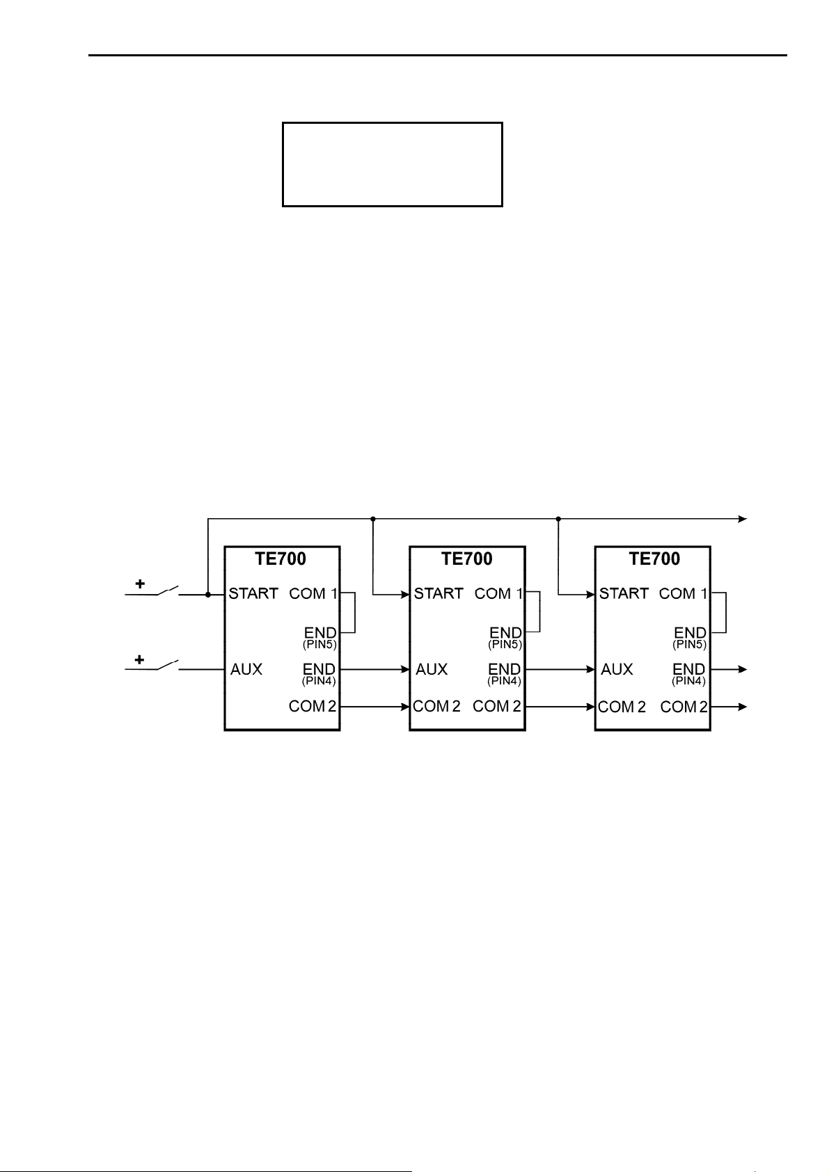
TECNA S.p.A. ITEM TE700 Instruction Manual
CHAPTER 4 – CASCADE OPERATING MODE
FEATURES TE700
BIC 1-2 NC OFF
SEAM WELD MODE OFF
>CASCADE MODE ON
This function allows the cycle-end signal to be normally closed instead of normally open. As
such, multiple TE700 control units may work in electrical cascade mode.
When two or more control units are connected to one another, the signals used to
synchronize control units and carry out electrical cascade welds are as follows:
- START CYCLE input
- AUX input
- CYCLE END output
All the TE700 control units receive the cycle start signal simultaneously. Connect the CYCLE
END signal to the AUX input of the next control unit. It is advisable to program parameter
CASCADE MODE, of the last control unit, to OFF in order to use the CYCLE END signal with
the normally open contact
The cascade WORKING MODE excludes the possibility of using the control unit in SEAM WELD MODE.
97/128
Page 98
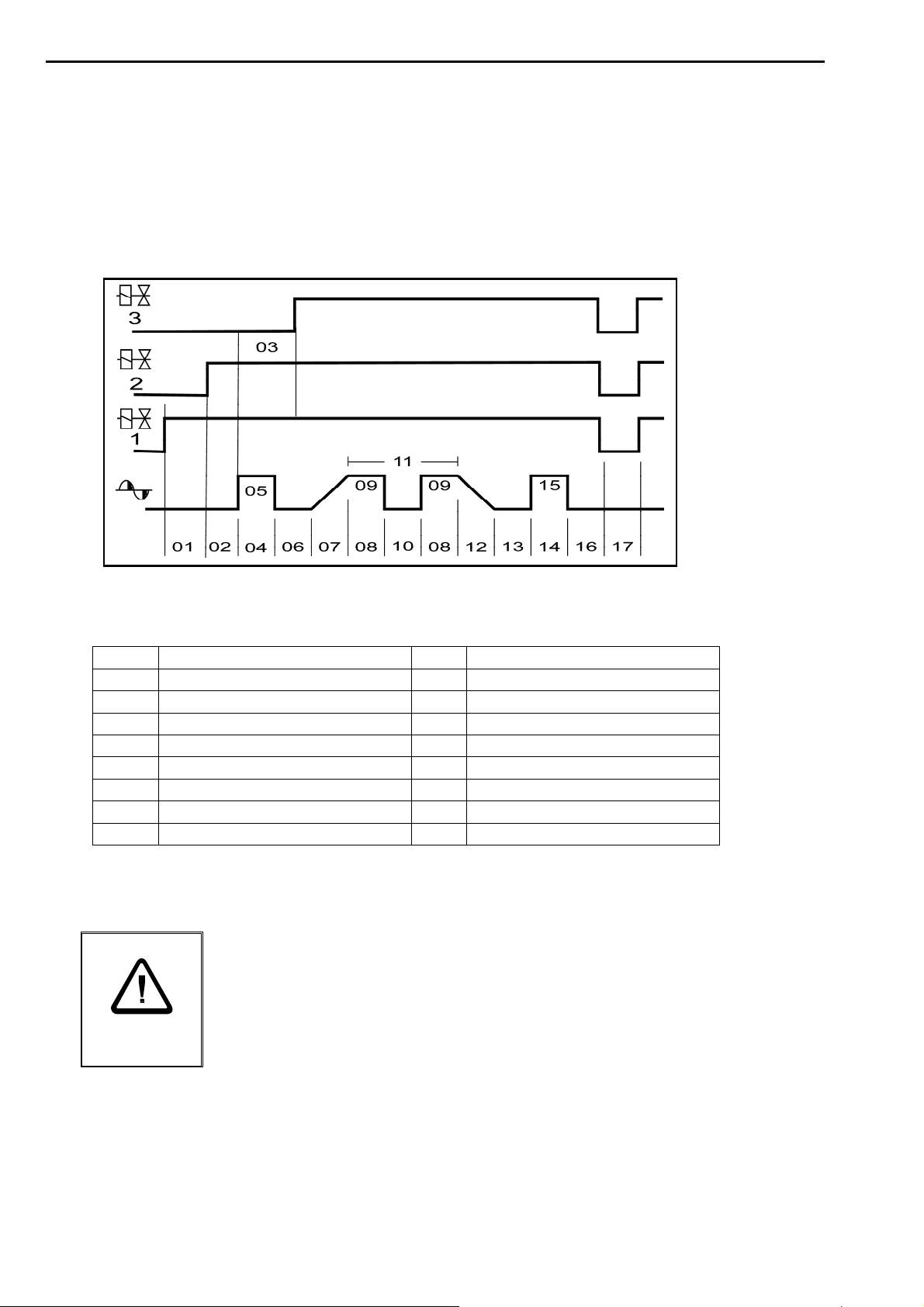
Instruction Manual ITEM TE700 TECNA S.p.A.
CHAPTER 5 – DESCRIPTION OF THE WORK CYCLE
The work cycle carried out by the TE700 is described by adjusting the programming
parameters. These parameters describe operating times and current adjustments that make
up the work cycle when run in sequence.
The following chart shows the sequence in which the programmed functions are carried out.
The numbers below refer to the following types of parameters:
01
02
03
04
05
06
07
08
09
SQUEEZE 1 (EV1)
SQUEEZE (EV2) *
FORGE DELAY (EV3) *
PRE-WELD *
PRE-POWER *
COLD 1 *
SLOPE UP
WELD
POWER / CURRENT
COLD 2
10
IMPULSE N.
11
SLOPE DOWN *
12
COLD 3 *
13
POST-WELD. *
14
POST-POWER *
15
HOLD TIME
16
OFF TIME
17
Parameters marked by symbol * may either be enabled or disabled depending on which
welder is used and the job it must perform.
For safety reasons, the microprocessor does not start the weld cycle
if the cycle start signal is activated on turning-on the welder.
Therefore simply release the control and then activate it again.
Micro-cutoffs or excessive voltage drops do not alter the WORKING
MODE but just stop the control unit. Just turn off the machine and
then turn it on again to restore operations.
98/128
Page 99
TECNA S.p.A. ITEM TE700 Instruction Manual
CHAPTER 6 - STOP BAD SPOTS
The machine may be stopped when a consecutive series of welds fall out of the regulated
limits. The number of consecutive welds that cause the control unit to stop is adjusted through
parameter STOP BAD SPOTS in the SETUP MENU (for the programming directions, see the
relevant paragraph).
SETUP MENU
>STOP BAD SPOT T1 01
STOP BAD SPOT T2 00
STOP BAD SPOT T3 00
This value may range from 0 to 15. On programming the value to 0, the function is disabled.
As such, on exceeding the preset limits, this does not stop the welder. There are four STOP
SPOTS parameters, one for each available welding tool, so as to be able to differentiate the
max number of admissible out of limits spots for each tool used.
It must be pointed out that in order to count the out of limits welds, they must be
consecutive, one after the other. This is applicable to each tool used.
In addition to activating the function in the SETUP MENU, the operator must enable the
CONTROL MODE parameter relevant to the current limits in the PROGRAM DATA menu.
PROGRAM DATA T1
TOOLS N° 1
WORKING MODE IK
>CONTROL MODE CUR
These parameters allow the operator to keep the consistency of the welding current under
control to help achieve constant quality results.
The control unit enables to select two different control modes:
Welding current limits
This mode is activated by setting parameter CONTROL MODE to CUR.
Two new parameters will be displayed:
LIM I MIN lower current limit
LIM I MAX upper current limit
These two parameters enable to set the welding current limit-values.
PROGRAM DATA T1
TOOLS N° 1
WORKING MODE IK
>CONTROL MODE CUR
PROGRAM DATA T1
>PAUSE 00
LIM I MIN 010.0kA
LIM I MAX 015.0kA
When the programmed condition occurs, the control unit stops and an error message is
displayed. The displayed message refers to the error condition of the last run weld. In current
control mode (CONTROL MODE = CUR), if the current value of the last weld is lower or
higher than the values set in the foregoing parameters, one of the following messages is
displayed:
STOP BAD SPOT MAX T1
WELD CURRENT [201]
LIMIT LOW
STOP BAD SPOT MAX T1
WELD CURRENT [202]
LIMIT HIGH
99/128
Page 100
Instruction Manual ITEM TE700 TECNA S.p.A.
S
PUSH [///] TO RESET
PUSH [///] TO RESET
Inverter use percentage limits
Activate this mode by setting the CONTROL MODE parameter to RO.
Two new parameters will be displayed:
LIM RO MIN lower limit of the power semiconductors conduction percentage.
LIM RO MAX upper limit of the power semiconductors conduction percentage.
that permit setting limit values on the conduction percentage of the power semiconductors.
PROGRAM DATA T1
TOOLS N° 1
WORKING MODE IK
>CONTROL MODE RO
PROGRAM DATA T1
>PAUSE 00
LIM RO MIN 006.0%
LIM RO MAX 020.0%
In conduction percentage control mode (CONTROL MODE = RO), if the value of the
conduction percentage of the last weld is higher or lower than the values set in the foregoing
parameters, one of the following messages is displayed:
STOP BAD SPOT MAX T1
RO [203]
LIMIT LOW
PUSH [///] TO RESET
TOP BAD SPOT MAX T1
RO [204]
LIMIT HIGH
PUSH [///] TO RESET
Limits on secondary voltage
Activate this mode by setting the CONTROL MODE parameter to VE.
Two new parameters will be displayed:
LIM V MIN lower limit on the secondary voltage
LIM V MAX upper limit on the secondary voltage
that permit setting limit values on the secondary voltage during the welding operation
PROGRAM DATA T1
TOOLS N° 1
WORKING MODE IK
>CONTROL MODE VE
PROGRAM DATA T1
>PAUSE 00
LIM V MIN 00.50V
LIM V MAX 01.20V
In secondary voltage control mode (CONTROL MODE = VE), if the value of the secondary
voltage is higher or lower than the values set in the foregoing parameters, one of the following
messages is displayed:
STOP BAD SPOT MAX T1
SECONDARY VE [205]
LIMIT LOW
PUSH [///] TO RESET
STOP BAD SPOT MAX T1
SECONDARY VE [206]
LIMIT HIGH
PUSH [///] TO RESET
100/128
 Loading...