

Page 1
TECNA® S.p.A.
DOCUMENT
DISTRIBUTOR:
USER MANUAL
From version 1.10
Via Meucci 27 - 40024 Castel S. Pietro Terme – Bologna ITALY
Tel. +39 0516954411 – Fax +39 0516954490 – http://www.tecna.net
NUMBER:
EDITION: April 2014
MAN 5017
Page 2

TECNA WELD TESTER TE1700
SUMMARY
1.0 MAIN MENU ................................................................................................ 3
2.0 MEASUREMENT MENU ............................................................................... 6
2.1 MEASUREMENT GRAPH .......................................................................... 8
2.2 MEASUREMENT GRAPH CONFIGURATION ........................................... 11
2.3 MEASUREMENT DATA ........................................................................... 13
2.4 MEASUREMENT DATA CONFIGURATION .............................................. 20
2.5 MEASUREMENT CONFIGURATION ........................................................ 22
2.5.1 ADVANCED MEASUREMENT CONFIGURATION ............................. 26
2.6 SETTING LIMITS ..................................................................................... 28
2.7 WELDING TABLE .................................................................................... 33
3.0 STATISTICS MENU ..................................................................................... 35
3.1 SCATTER PLOT ....................................................................................... 37
4.0 DATA SAVING MENU ................................................................................. 39
4.1 MEASUREMENT GRAPH CONFIGURATION ........................................... 41
5.0 INSTRUMENT CONFIGURATION MENU .................................................... 43
5.1 BLUETOOTH CONFIGURATION MENU .................................................. 46
6.0 CONNECTING THE INSTRUMENT TO THE PC ............................................... 50
6.1 PUTTY© TERMINAL EMULATOR ........................................................... 57
6.1.1 MAIN MENU ................................................................................... 59
6.1.2 DATA SPOT PRINT........................................................................... 60
6.1.3 INSTRUMENT CONFIG MENU ......................................................... 62
6.1.4 CURRENT CONFIG MENU ............................................................... 64
6.1.5 LIMIT CONFIG MENU...................................................................... 65
7.0 ERROR MESSAGES ..................................................................................... 67
8.0 INSTRUMENT FEATURES ........................................................................... 69
9.0 MEASURING ACCESSORIES ........................................................................ 70
10.0 BATTERY REPLACEMENT AND PRODUCT LIFE END ................................. 71
11.0 SAFETY OF USE ........................................................................................ 72
PAGE 2
Page 3
TECNA WELD TESTER TE1700
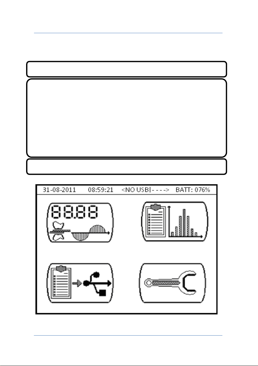
Indication of current date and time in format dd-mm-yyyy and hh:mm
BATT: 076% Indication of residual battery charge
1.0 MAIN MENU
Indicator of USB pen-drive and status of connection with expansion
card.
<NO USB| > pen-drive not inserted or not recognised
<USB OK| > pen-drive inserted and recognised
< |- - - - > expansion card absent
< |LINK> card present and connection established
< |!LN!> card present and connection not established
PAGE 3
Page 4
TECNA WELD TESTER TE1700
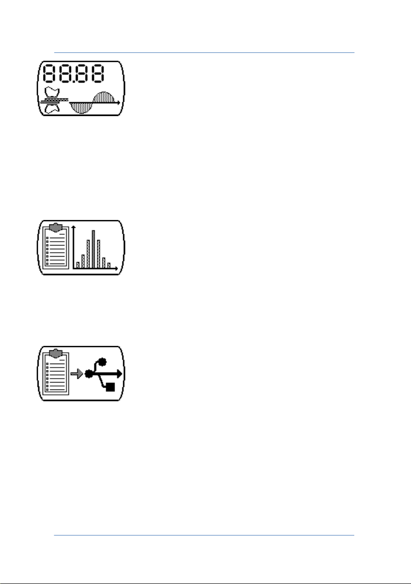
Key for accessing the TE1700 measuring functions. In this menu you
can configure the ranges of the probes, LIMITS, PULSE, PRE-BLANK and
POST-BLANK, TRIGGER LEVEL, FORCE FILTER, TRIGGER TYPE and the
NORMAL/CONTINUOUS mode. You can also read the numeric values of
the measured quantities and view them on a graph.
Key for accessing the TE1700 statistics menu. It provides a statistical
analysis with a scatter plot on the last 90 weld spots performed by the
instrument.
Key for accessing the menu to save data on a pen-drive. It allows you
to save the bitmap chart of the measured quantities or to export the
spots to a .CSV (Comma-Separated Values) file to perform off-line
analyses.
PAGE 4
Page 5
TECNA WELD TESTER TE1700
Key for accessing the instrument's configuration menu, which allows
you to configure:
• Time to turn off the display backlight;
• Auto-shutoff time to save battery;
• Current date and time;
• Local network supply frequency, 50 or 60 Hz;
• Which data to save of every spot, NORMAL or ADVANCED
mode;
• Update TE1700 firmware;
• Connected Bluetooth devices (e.g.: PC, TE1710 Expander, etc.).
PAGE 5
Page 6
TECNA WELD TESTER TE1700
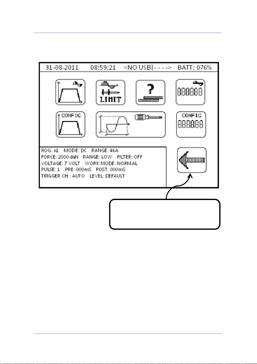
Pressing BACK returns to the
2.0 MEASUREMENT MENU
Summary of current measuring instrument configuration, including the
following information:
• Type of current transducer, type of source to be measured,
selected measuring range.
• Type of force transducer, selected measuring range,
disturbance limitation activation.
PAGE 6
previous screen
Page 7

TECNA WELD TESTER TE1700
• Selected measuring range for voltage, normal or continuous
measuring mode.
• Number of current pulses, initial and final masking on signal to
be measured.
• Selection of channel for measurement, either force or current
or both, instrument sensitivity for starting measuring
operations.
PAGE 7
Page 8

TECNA WELD TESTER TE1700
2.1 MEASUREMENT GRAPH
Available in NORMAL mode only
Allows you to access the measured quantities graph with respect to
time.
This function is only active in NORMAL work mode and is not available
in CONTINUOUS mode.
You can view a maximum of two quantities on the graph, chosen
among welding current, secondary voltage, energy and resistance.
Force is plotted on its own on a dedicated graph, while the other
quantities can be selected independently; quantities are chosen from
the MEASUREMENT GRAPH CONFIGURATION menu.
Acquiring spots while inside the MEASUREMENT GRAPH screen will
decrease the max acquisition rate.
The MEASUREMENT GRAPH screen appears empty when accessed
before the instrument has been able to perform a measurement.
PAGE 8
Page 9
TECNA WELD TESTER TE1700
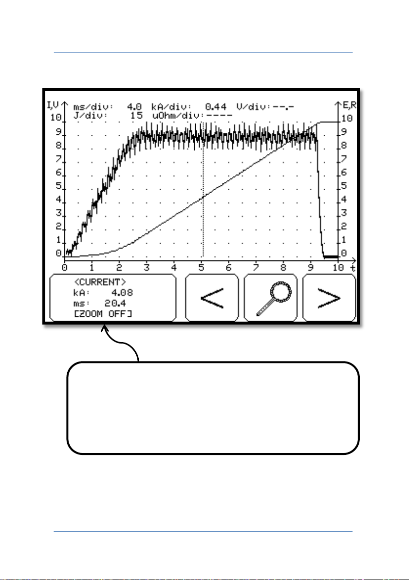
Messages relating to the current position of the cursor.
The measurement graph's screen is as follows:
The time position and the value of the selected quantity are
shown.
Touching this area changes the quantities to be plotted on
the graph.
PAGE 9
Page 10
TECNA WELD TESTER TE1700
The right and left arrows move the cursor horizontally, repeatedly
pressing the key moves the cursor quickly.
Zooms horizontally into the graph in the area of the cursor.
PAGE 10
Page 11
TECNA WELD TESTER TE1700
2.2 MEASUREMENT GRAPH CONFIGURATION
Available in NORMAL mode only
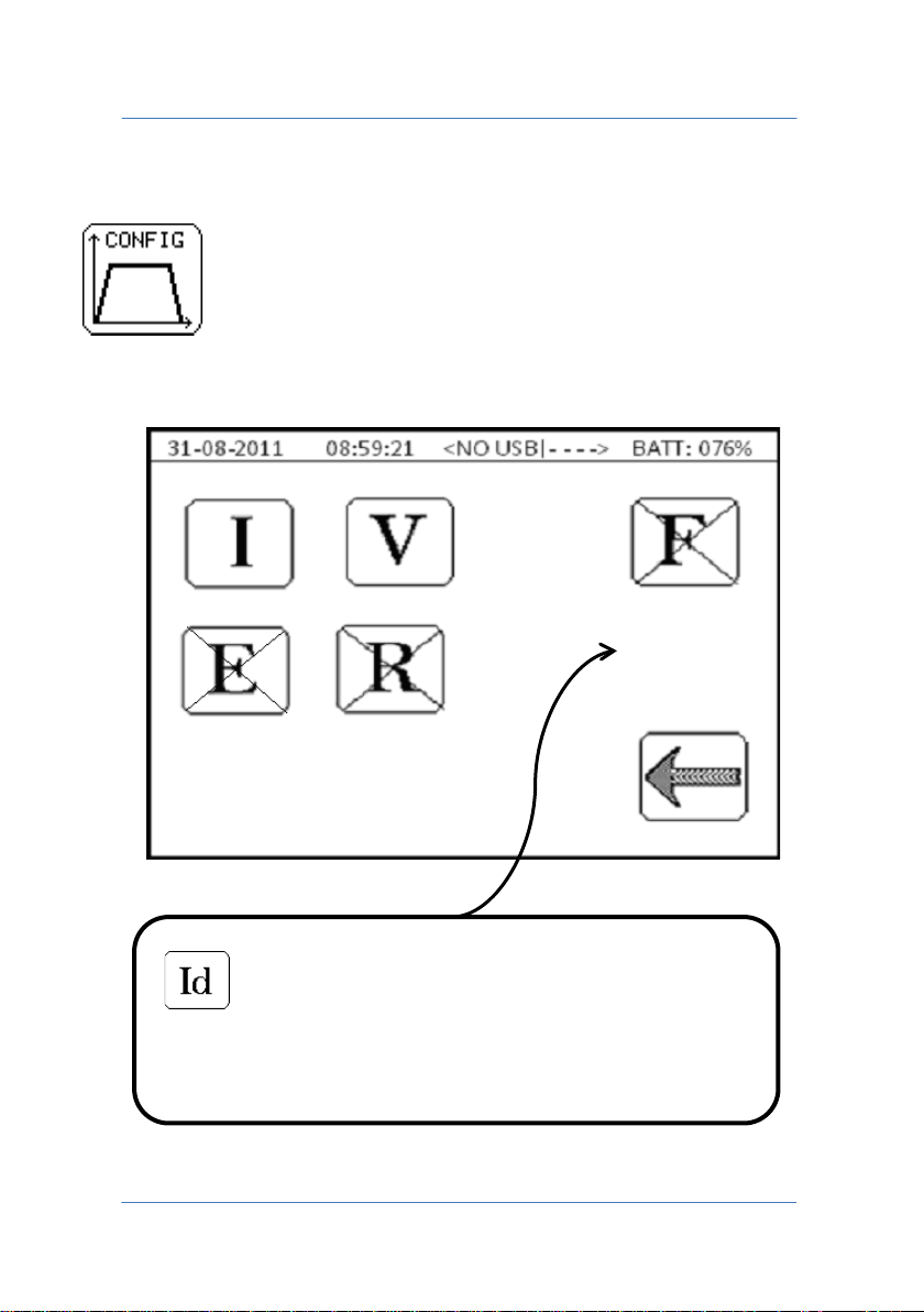
Selection of quantities to be viewed.
This icon is present only with the TE1710 Expander
expansion card.
Enables viewing of the displacement measurement graph.
PAGE 11
Page 12

TECNA WELD TESTER TE1700
You can simultaneously view a maximum of two quantities on the
graph; the selected quantities appear without the X whilst quantities
with the X are not shown in the graph.
If you wish to view the force graph, the other quantities will be
deactivated automatically.
I Welding current.
V Secondary voltage. Requires measurement of the voltage at the
electrodes.
E Energy dispensed during the weld. Requires measurement of the
voltage at the electrodes.
R Electrical resistance of the material. Requires measurement of the
voltage at the electrodes.
WARNING: in the event the voltage and current values are
considerably low, the electrical resistance value is forced to zero.
F Measurement of the force exerted by the electrodes during the
welding process.
PAGE 12
Page 13
TECNA WELD TESTER TE1700
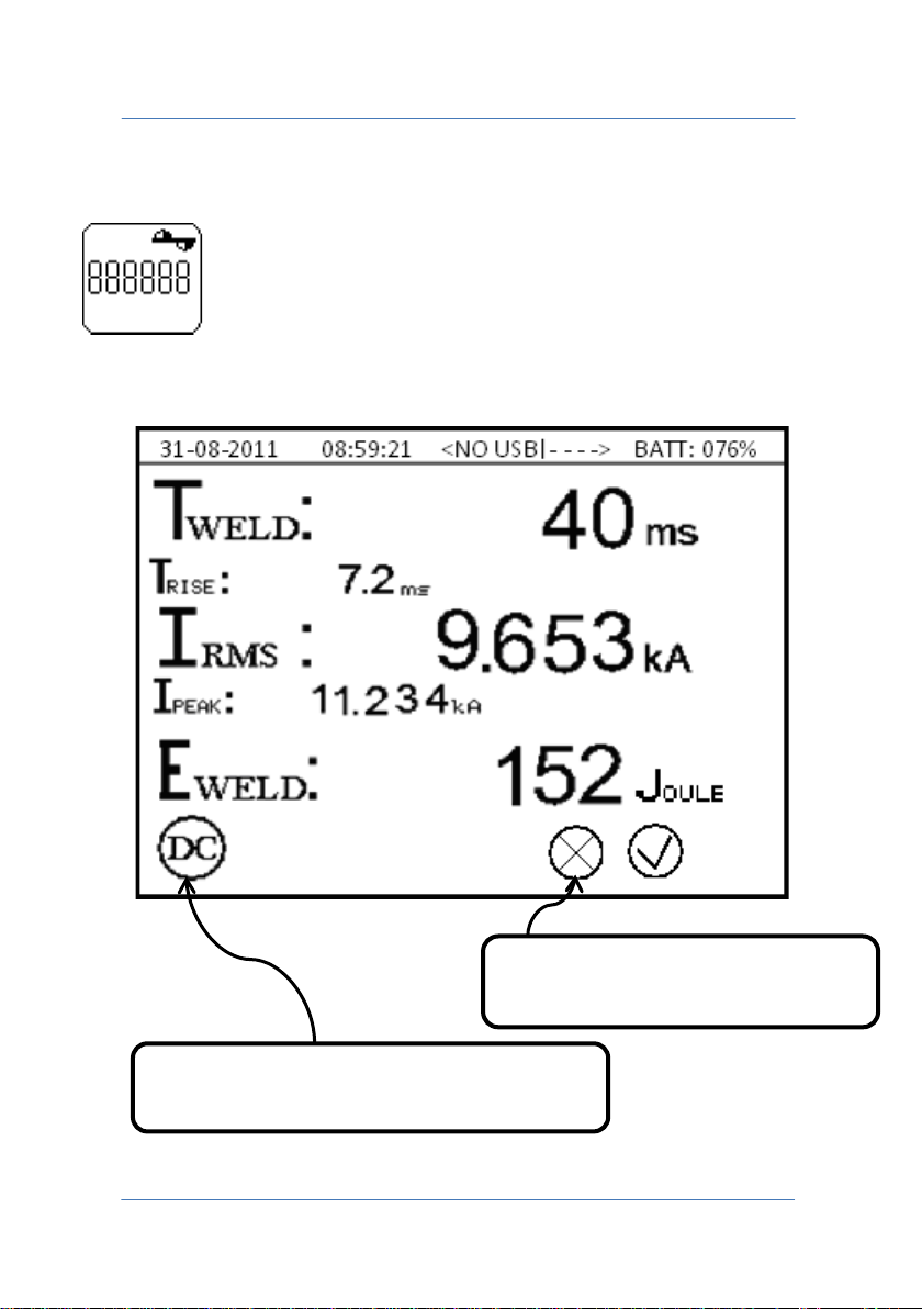
Indicator of active functions that can affect
the measurement process.
Indicator of execution of
measurement process.
2.3 MEASUREMENT DATA
Available in NORMAL and CONTINUOUS modes
Displays the numeric values of the quantities measured.
PAGE 13
Page 14
TECNA WELD TESTER TE1700
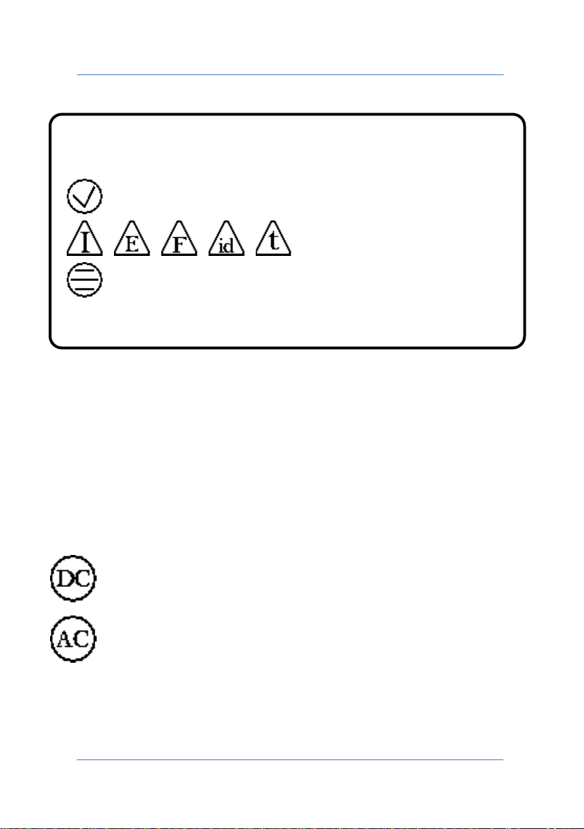
Indicator of outcome of check limits on the measurement process.
Measurement within limits.
Measurement outside limits.
Check limits not active.
The quantities displayed depend on instrument configuration and on
the selections made in the MEASUREMENT DATA CONFIGURATION
menu.
At the bottom of the screen, indicators show the active functions in
the TE1700 that can affect the numeric values shown on the display. A
list of data that can be viewed is as follows.
Measurement of a direct current source, such as medium
frequency inverter and three-phase unit.
Measurement of an alternate current source, single-phase
spot welder.
PAGE 14
Page 15
TECNA WELD TESTER TE1700
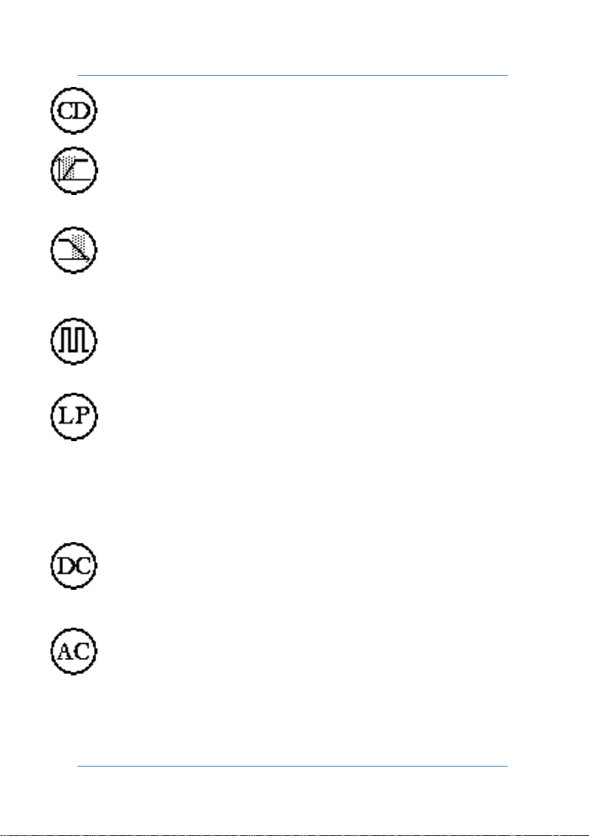
Measurement of a pulse type current, capacitor discharge.
PRE-BLANK active during the measurement, the initial part of
the welding process, for the set PRE-BLANK time, not
considered in the measurement process.
POST-BLANK active during the measurement, the final part of
the welding process, for the set POST-BLANK time, not
considered in the measurement process.
The set number of pulses is greater than 1; the weld to be
measured is pulsed and the number of pulses must be equal
to the value set on the control unit.
When FORCE FILTER is activated, it suppresses the noise on
the force measurement channel, recommended when using
electrical axes.
Welding time measurement is always present on the display. Displayed
data change, depending on the technology of the welder used:
The display indicates the total time dispensing T
and the time taken by the current to reach its maximum T
current
weld
rise
value.
The display indicates the total time dispensing T
current
weld
and the average conduction degrees DEG.
PAGE 15
Page 16
TECNA WELD TESTER TE1700
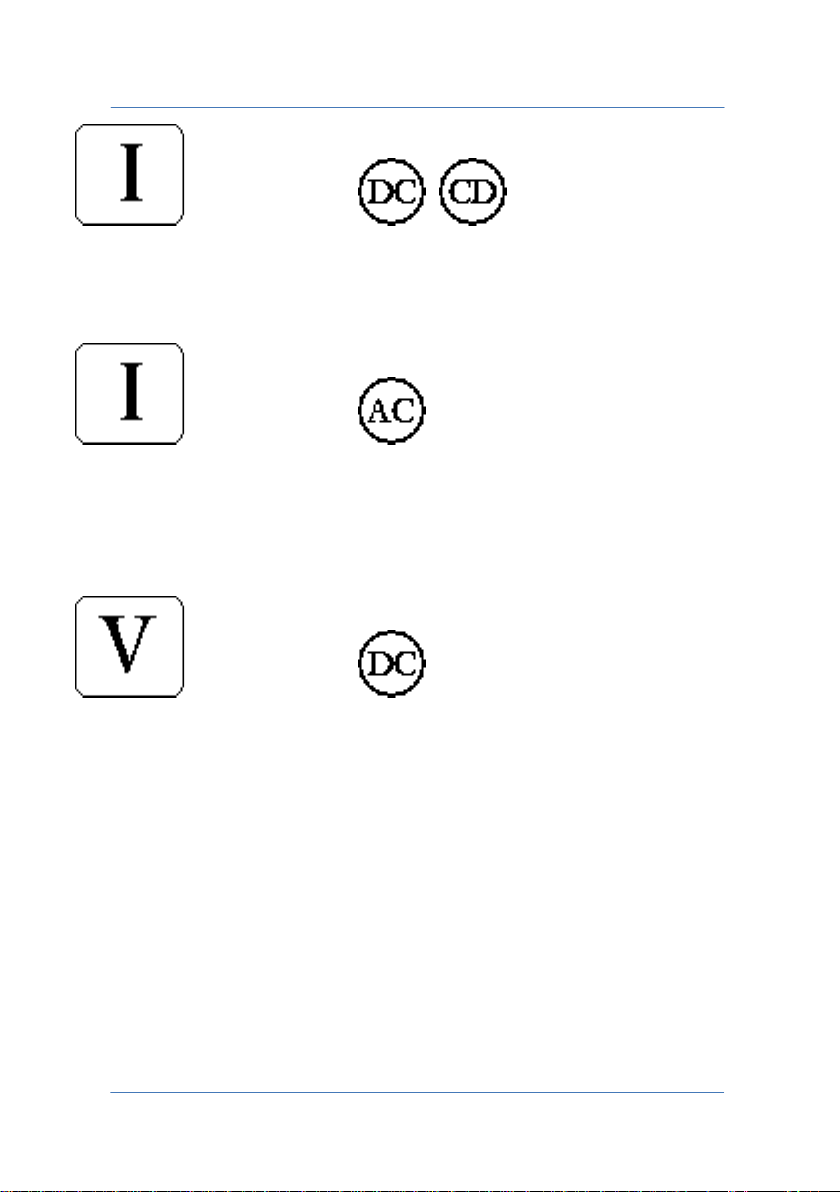
In modes
Welding current: the RMS value of the I
I
peak value reached during welding are displayed.
peak
welding current and the
RMS
In mode
Welding current: the RMS value of the I
max positive peak value and the I
max negative peak value reached
peak-
welding current, the I
RMS
during welding are displayed.
In mode
Secondary voltage: displays the RMS voltage value V
secondary circuit and its V
maximum peak value. To perform this
peak
present on the
rms
measurement, use the cables for measuring electrodes voltage.
peak+
PAGE 16
Page 17
TECNA WELD TESTER TE1700
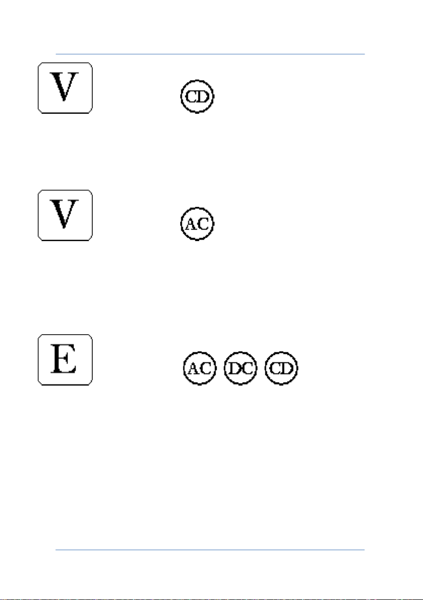
In mode
Secondary voltage: displays the voltage peak value V
during the
peak
welding process. To perform this measurement, use the cables for
measuring electrodes voltage.
In mode
Secondary voltage: displays the RMS voltage value V
secondary circuit, its maximum positive peak value V
maximum negative peak value V
. To perform this measurement,
peak-
present on the
rms
peak+
and
use the cables for measuring electrodes voltage.
In modes
Energy dispensed during the weld E
. To perform this measurement,
weld
use the cables for measuring electrodes voltage.
PAGE 17
Page 18
TECNA WELD TESTER TE1700
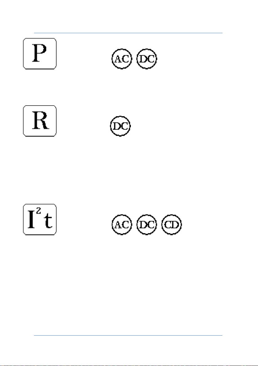
In modes
Average power dispensed during the welding process. To perform this
measurement, use the cables for measuring electrodes voltage.
In mode
Electrical resistance measured at the end of the welding process. This
value includes the electrical resistance of the piece to be welded and
the resistance of the secondary circuit included at both ends of the
electrodes of the voltage probe. To perform this measurement, use the
cables for measuring electrodes voltage.
In modes
Thermal current: the average I
current values are displayed. The average value T
and the instantaneous i
th
is calculated by
ith
thermal
Ith
processing the samples acquired over a maximum time range of 24
hours. The instantaneous value i
is obtained according to the last 2
Ith
welding samples performed. The average samples can be deleted.
PAGE 18
Page 19
TECNA WELD TESTER TE1700
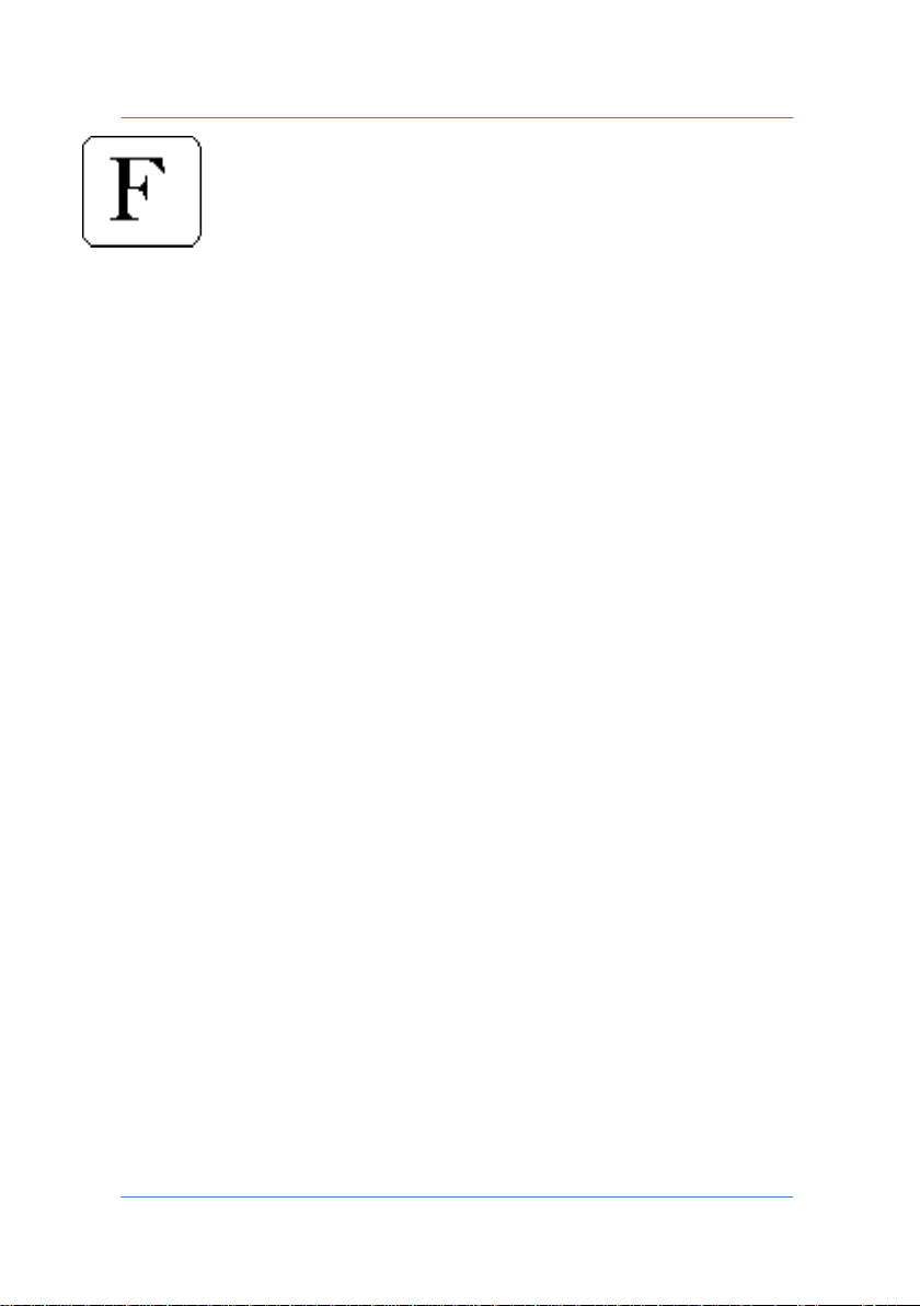
Force: supplies the maximum force F
beginning Fon of the welding and at the end F
during welding, at the
max
of the welding process.
off
If CONTINUOUS mode is selected, the data viewed cannot be edited by
the user. The data displayed are:
• RMS value of the welding current I
• Positive current peak I
• Negative current peak I
PEAK+
PEAK-
• RMS value of the secondary voltage V
• Positive voltage peak V
• Negative voltage peak V
PEAK+
PEAK-
RMS
RMS
• Continuous force value
In this case the force values are updated continuously and
automatically.
PAGE 19
Page 20
TECNA WELD TESTER TE1700
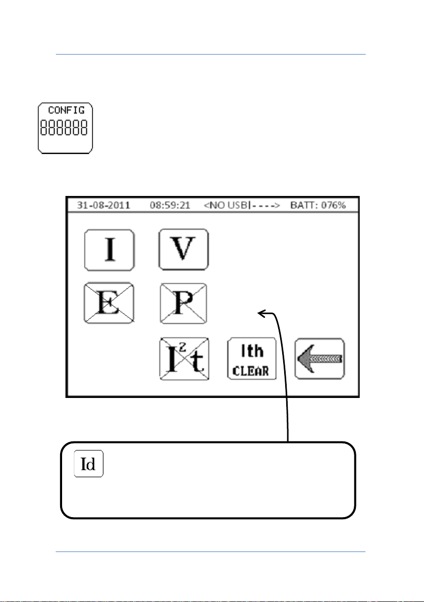
Enables a displacement measurement to be viewed.
2.4 MEASUREMENT DATA CONFIGURATION
Available in NORMAL mode only
Selection of quantities to be viewed.
This icon is present only with the TE1710 Expander
expansion card.
PAGE 20
Page 21

TECNA WELD TESTER TE1700
The selected quantities appear without the X whilst quantities with the
X will not be shown in the measurement data; a maximum of 2
electrical quantities can be displayed simultaneously.
I Welding current.
V Secondary voltage. Requires measurement of the voltage at the
electrodes.
E Energy dispensed during the weld. Requires measurement of the
voltage at the electrodes.
P Power dispensed during the weld. Requires measurement of the
voltage at the electrodes.
I2t Thermal current Ith of the welding process performed.
Ith CLEAR Deletion of the thermal current samples Ith of the
welding process performed.
PAGE 21
Page 22
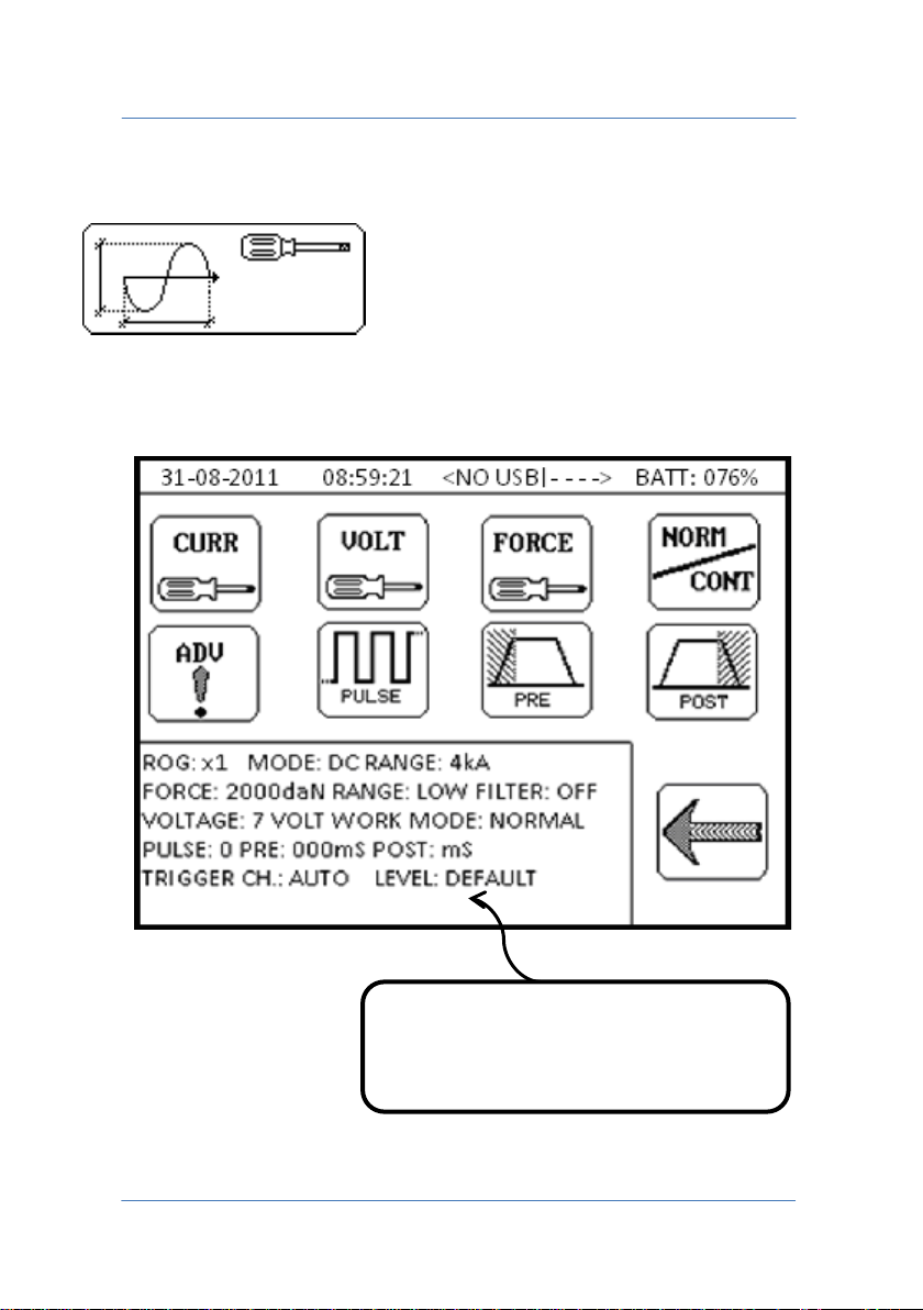
TECNA WELD TESTER TE1700
Summary of current instrument
2.5 MEASUREMENT CONFIGURATION
Configuration of the modes in which acquired quantities are
measured.
configuration
PAGE 22
Page 23
TECNA WELD TESTER TE1700
Available in NORMAL and CONTINUOUS modes
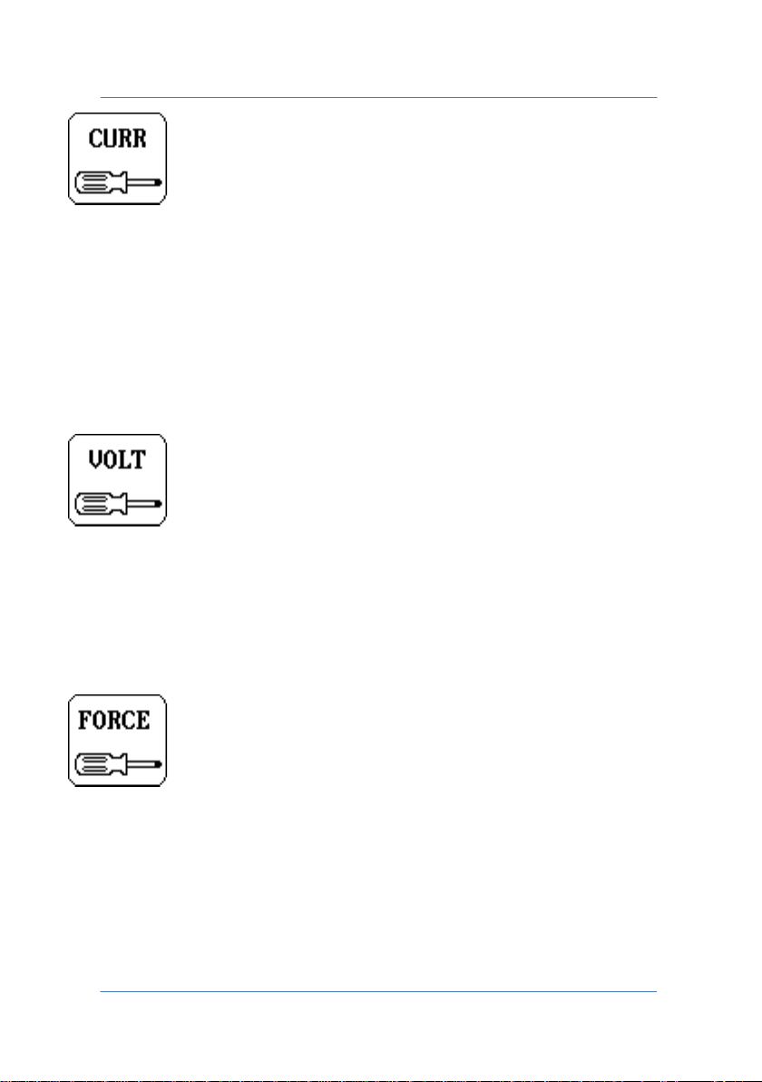
CURR - For choosing the technology of the welder used: AC, DC or CD,
and also the range with which to perform the measurement. Be sure to
choose the range appropriately because if you select one that is too
low, error CURRENT HIGH OVER RANGE will appear but if you select
one that is too high, measurement accuracy will be lost. The key is
active solely if the instrument is connected to a current transducer.
Available in NORMAL and CONTINUOUS modes
VOLT - Allows you to set the electrodes' voltage range. Be sure to
choose the range appropriately because if you select one that is too
low, error VOLTAGE HIGH OVER RANGE will appear but if you select
one that is too high, measurement accuracy will be lost.
Available in NORMAL and CONTINUOUS modes
FORCE - Allows you to set the force measuring range. Be sure to
choose the range appropriately because if you select one that is too
low, error FORCE HIGH OVER RANGE will appear but if you select one
that is too high, measurement accuracy will be lost. The key is active
solely if the instrument is connected to a force transducer.
PAGE 23
Page 24
TECNA WELD TESTER TE1700
Available in NORMAL and CONTINUOUS modes
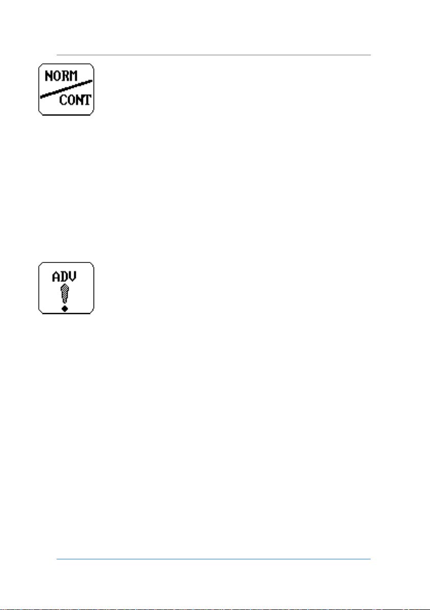
NORM/CONT - Allows you to switch from NORMAL to CONTINUOUS
operating mode and vice versa. In NORMAL mode the instrument
awaits the TRIGGER activation to acquire the spot whilst in
CONTINUOUS mode the instrument acquires current, voltage and force
values continuously. You can activate the CONTINUOUS mode only if
the welder has the AC technology, or if the current transducer is
disconnected from the instrument.
Available in NORMAL and CONTINUOUS modes
ADV - Makes advanced adjustments to the measurement process; see
the relative chapter ADVANCED MEASUREMENT CONFIGURATION.
PAGE 24
Page 25
TECNA WELD TESTER TE1700
Available in NORMAL mode
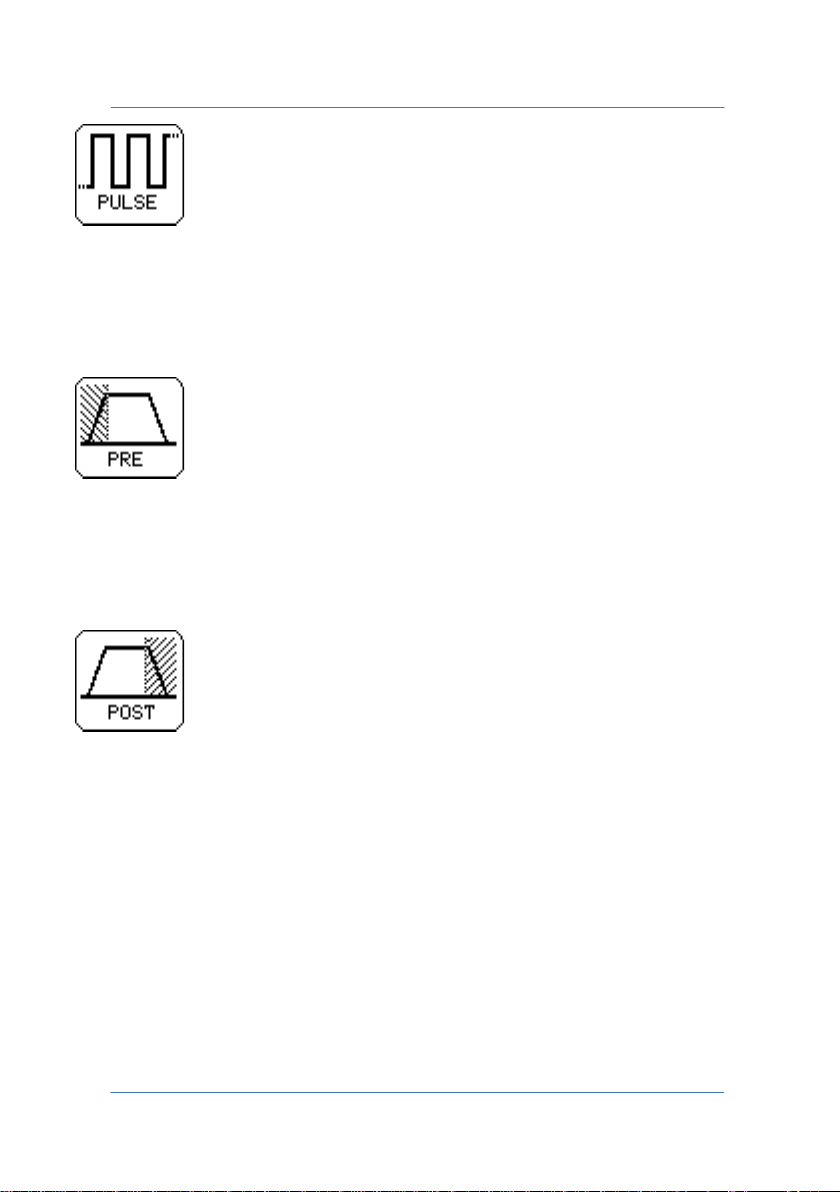
PULSE - Allows you to set the number of pulses. The number of pulses
entered must be equal to the number of pulses set on the welding
control.
Available in NORMAL mode
PRE BLANK - Sets the PRE BLANK time; if other than zero the initial part
of the welding process, for the set time, is not considered in the
measurement process.
Available in NORMAL mode
POST BLANK - Sets the POST BLANK time; if other than zero the final
part of the welding process, for the set time, is not considered in the
measurement process.
PAGE 25
Page 26
TECNA WELD TESTER TE1700
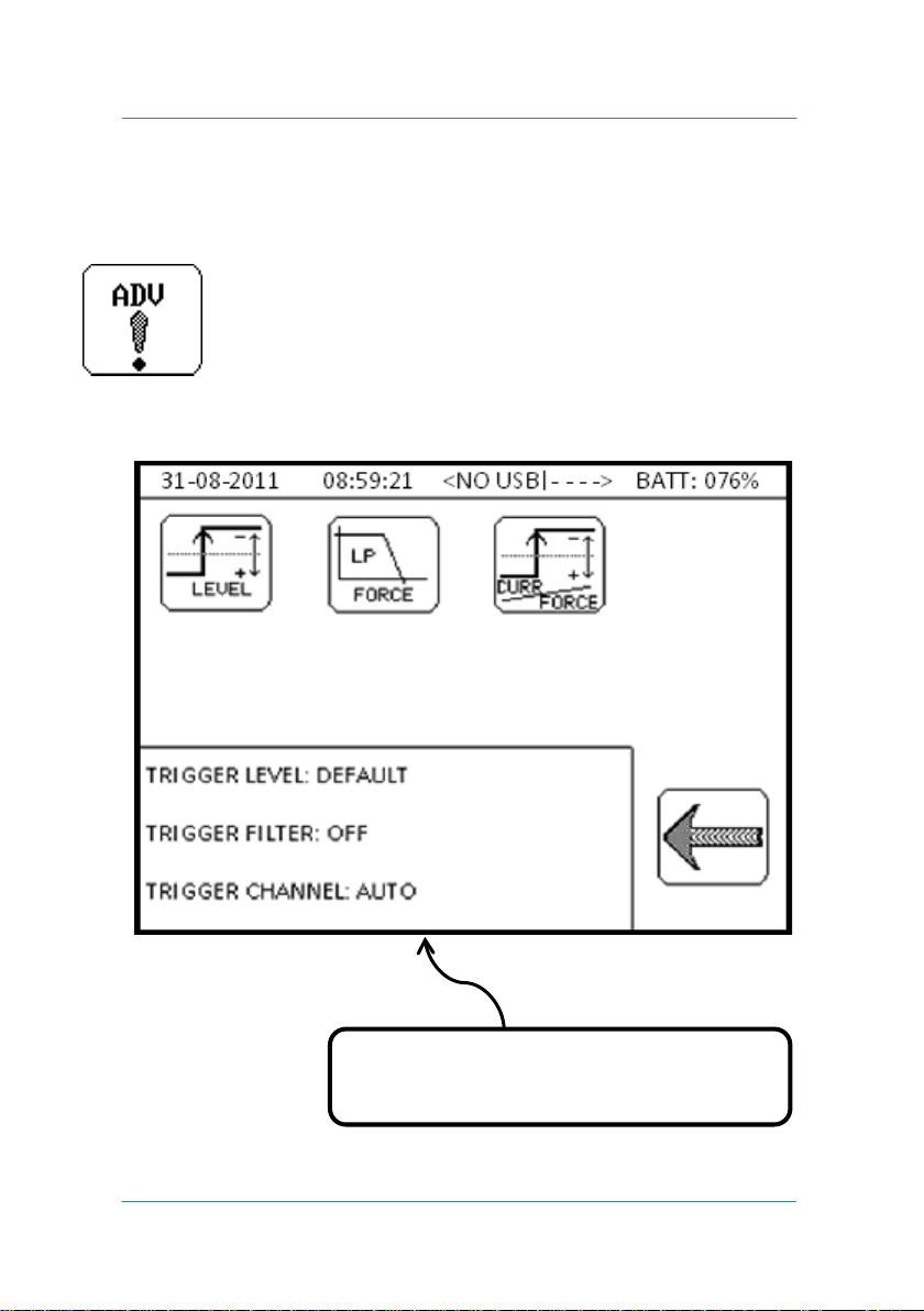
Summary of current instrument
2.5.1 ADVANCED MEASUREMENT CONFIGURATION
For setting the instrument to measure under special conditions.
configuration
PAGE 26
Page 27
TECNA WELD TESTER TE1700
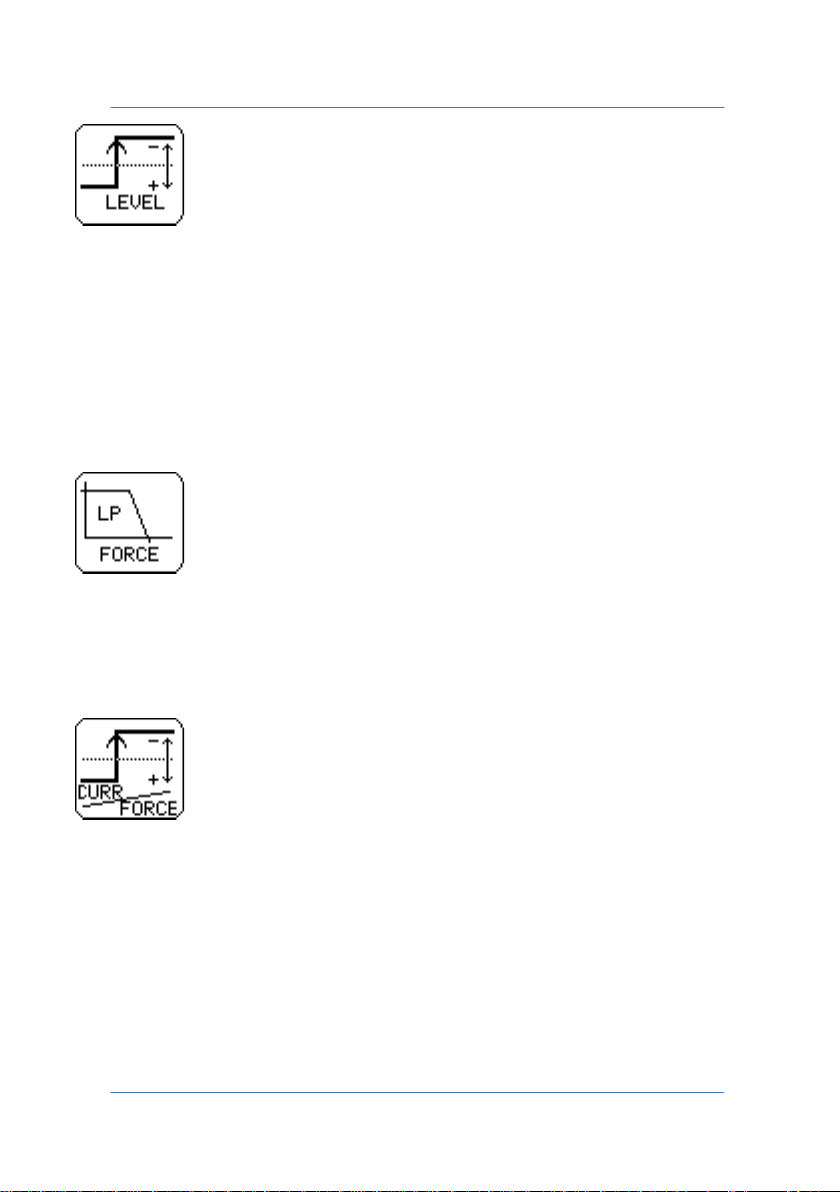
TRIGGER LEVEL - For changing the sensitivity with which the
instrument recognises the start of the welding process. High
sensitivities enable low current or force values to be measured
correctly. While lower sensitivities allow measurements to be
performed in environments with high electrical disturbance or
mechanical vibration.
FORCE FILTER - For activating a filter on the disturbances present on
the force measurement, which can occur in the presence of an
electrical axis.
TRIGGER TYPE - The instrument normally receives the welding process
start signal on both the current and the voltage channel; one of the
two channels may be excluded from receiving the welding process
start signal.
PAGE 27
Page 28
TECNA WELD TESTER TE1700
2.6 SETTING LIMITS
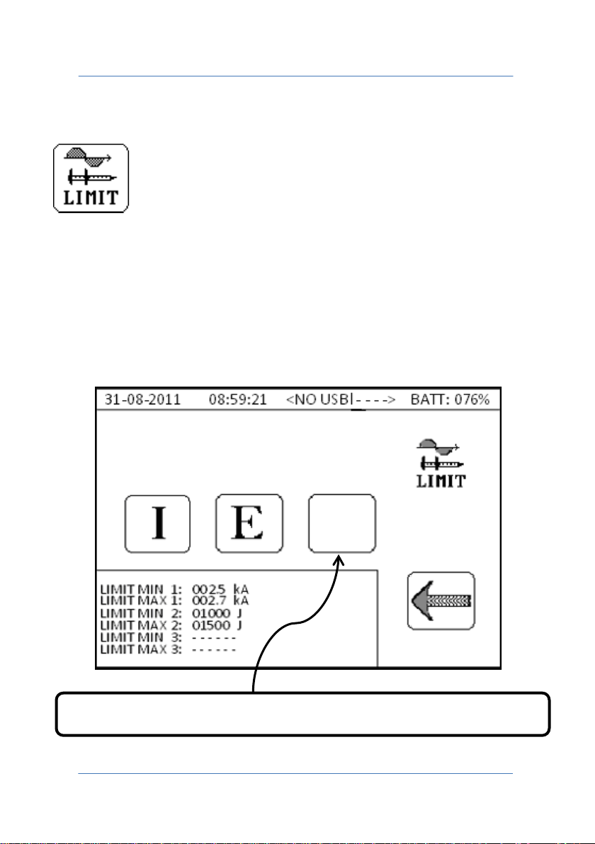
LIMIT - A control mask is associated with each acquired weld spot, with
three weld limits that may be selected among the following quantities:
current, energy, time, force and displacement. You cannot select two
identical quantities from the limits mask. If using the TE1710 Expander,
you can configure up to 15 limits masks through the control unit's call
signals.
Enables access to the welding limit programming menu.
PAGE 28
Page 29
TECNA WELD TESTER TE1700
In the limits mask image shown in the page above, it can be noted that
current and energy limits are active whilst the third limit is not.
As a general rule, the following assumptions are true:
• If the MIN and MAX fields coincide, the welding limits on the
quantity selected are not active.
• Within the mask, it is not possible to select the same quantity
for different welding limits.
Always referring to the image in the previous page, the three buttons
allow you to access the programming page of the first, second and
third welding limit of the selected control mask.
PAGE 29
Page 30
TECNA WELD TESTER TE1700
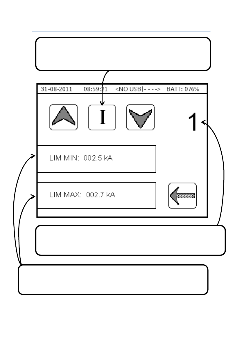
Welding limit quantity selector, to be monitored in the
active.
measurement process. If “blank”, the welding limit is not
Numeric indicator of the limits mask, selected via the control unit's
Press the LIM MIN and LIM MAX keys to edit the minimum and
maximum welding limit values.
PAGE 30
call signals. Can be between 1 and 15.
Page 31
TECNA WELD TESTER TE1700
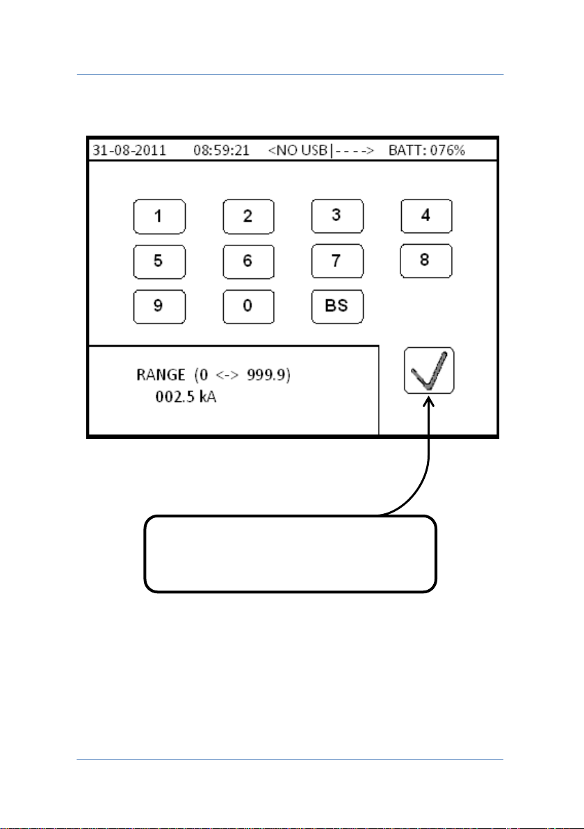
Confirms and returns to the previous
menu.
PAGE 31
Page 32
TECNA WELD TESTER TE1700
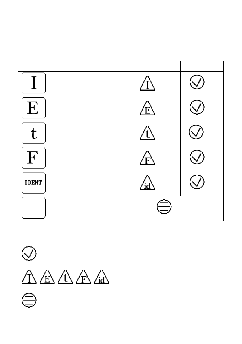
Type
Minimum
Maximum
Limit
OK
Below is the key to the welding limits managed by the measuring
instrument.
000.0 kA 999.9 kA
00000 J 60000 J
0000 mS 9999 mS
0000.0 daN 6000.0 daN
0.000 mm 9.999 mm
- - - - - - - - - - - -
The outcome of the measurement is shown at the bottom right of the
MEASUREMENT DATA screen at the end of the acquisition process.
NO LIMITS
OK
OK
OK
OK
OK
PAGE 32
measurement within limits.
measurement outside limits.
Limits not active.
Page 33
TECNA WELD TESTER TE1700
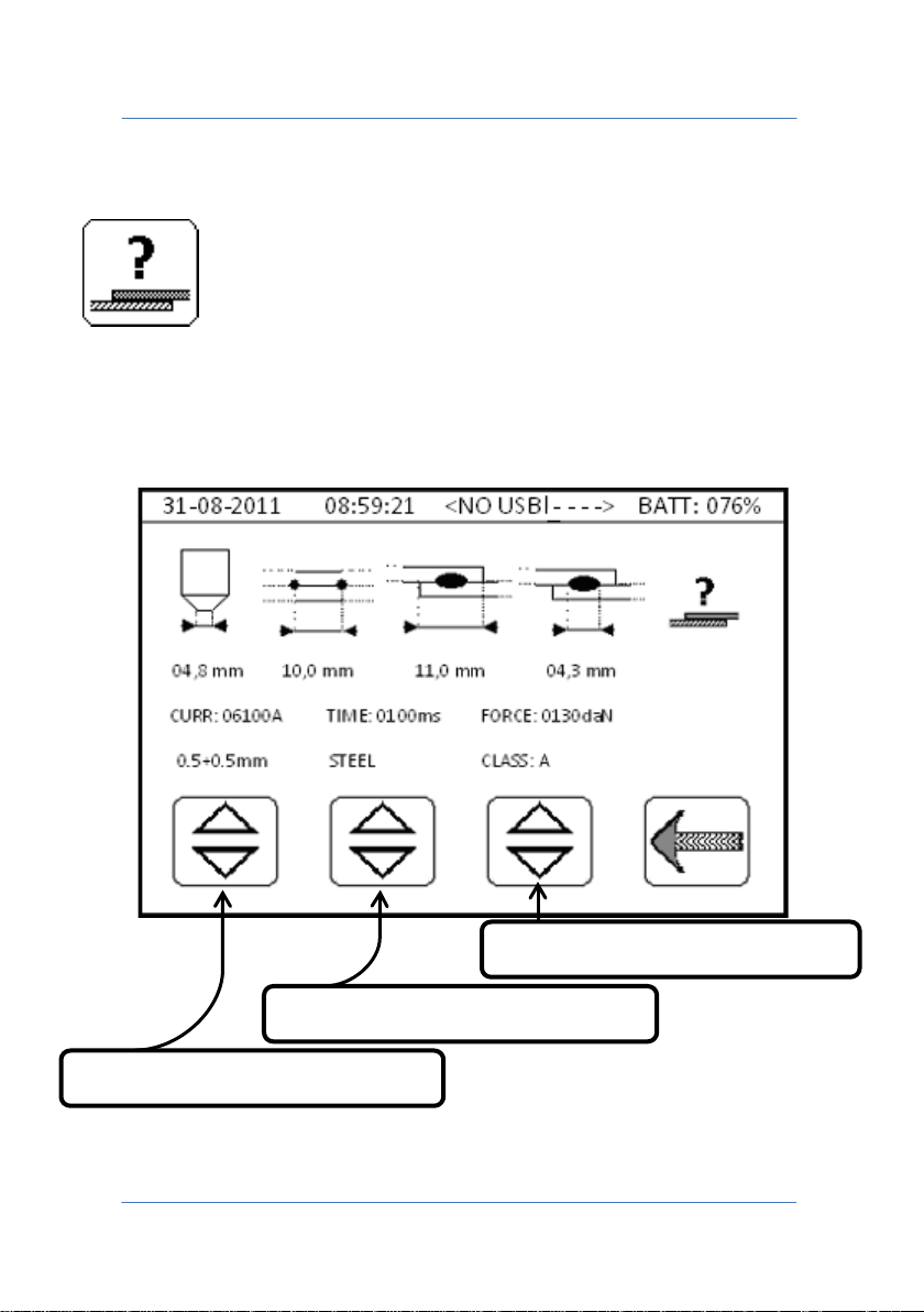
Sheet MATERIAL selection.
Sheet THICKNESS selection.
Sheet quality CLASS selection.
2.7 WELDING TABLE
For accessing the welding tables inside which the operator can retrieve
the welding parameters, selecting thickness, type of material and
quality class "A-B-C" of the sheets or parts being welded.
PAGE 33
Page 34

TECNA WELD TESTER TE1700
In addition to the current, time, force and electrode diameter
parameters, some data on the spatial positioning of the sheets or parts
being welded are also displayed.
These data are for information purposes only and must be viewed
solely by qualified technicians.
PAGE 34
Page 35
TECNA WELD TESTER TE1700
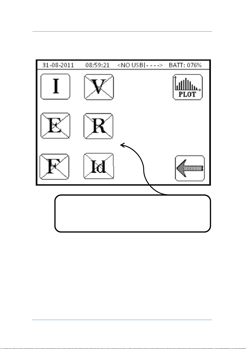
Selection of the quantity on which statistical analysis
3.0 STATISTICS MENU
Using this function, it is possible to run a statistical analysis of the last
90 spots recorded by the measuring instrument.
Before performing the analysis, select which quantity is to be analysed
among current, voltage, energy, resistance, force or displacement.
PAGE 35
is to be carried out. Only one quantity at a time can be
analysed.
Page 36

TECNA WELD TESTER TE1700
If you want to perform a more complex analysis, you can export the
data of a .CSV file (Comma-Separated Values) to a pen-drive. Later on,
you may use a spreadsheet to process the exported data and perform
a more in-depth analysis.
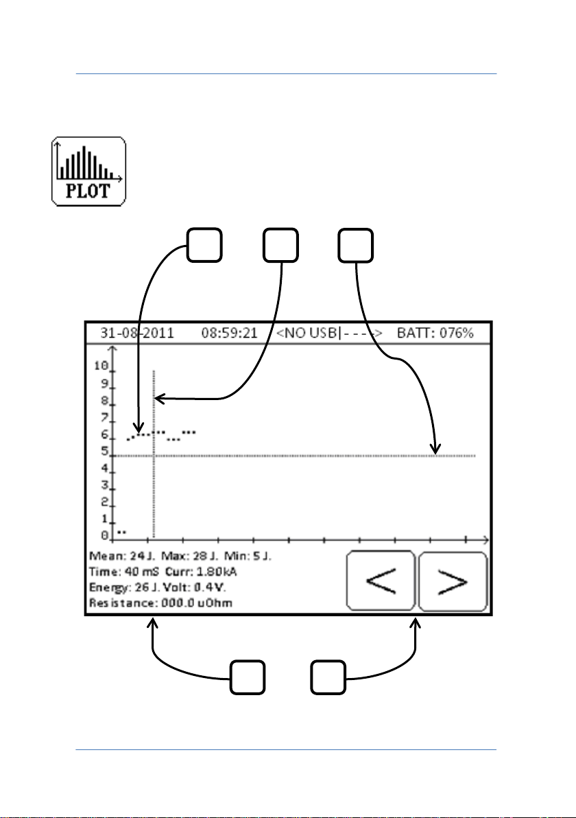
The analysis run by the instrument uses a scatter plot, which shows the
distribution of the various values of the selected quantity compared to
its average value. A vertical cursor can be used to examine all the data
relating to each spot shown on the graph.
PAGE 36
Page 37
TECNA WELD TESTER TE1700
1 2 3
4
5
3.1 SCATTER PLOT
PAGE 37
Page 38

TECNA WELD TESTER TE1700
1. Representation of the welding spots performed on the graph.
2. The vertical cursor is moved with the left and right arrows, allowing
details of the selected spot to be viewed.
3. The horizontal cursor indicates the average value of the selected
quantity.
4. It displays the average, minimum and maximum value of the selected
quantity. It also displays the welding time, current, energy, voltage
and resistance of the spot selected using the vertical cursor.
5. Arrows for selecting the previous or the next spot using the vertical
cursor.
PAGE 38
Page 39
TECNA WELD TESTER TE1700
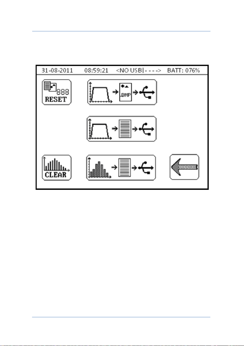
4.0 DATA SAVING MENU
The menu is for saving the data contained in the instrument to a pendrive for post-analysis or report creation.
WARNING: it is advisable to use USB 2.0 (or lower) pen-drive having
more than 1GB storage capacity formatted in FAT32.
Other types of formatting are not supported and therefore it will not
be possible to save data.
PAGE 39
Page 40
TECNA WELD TESTER TE1700
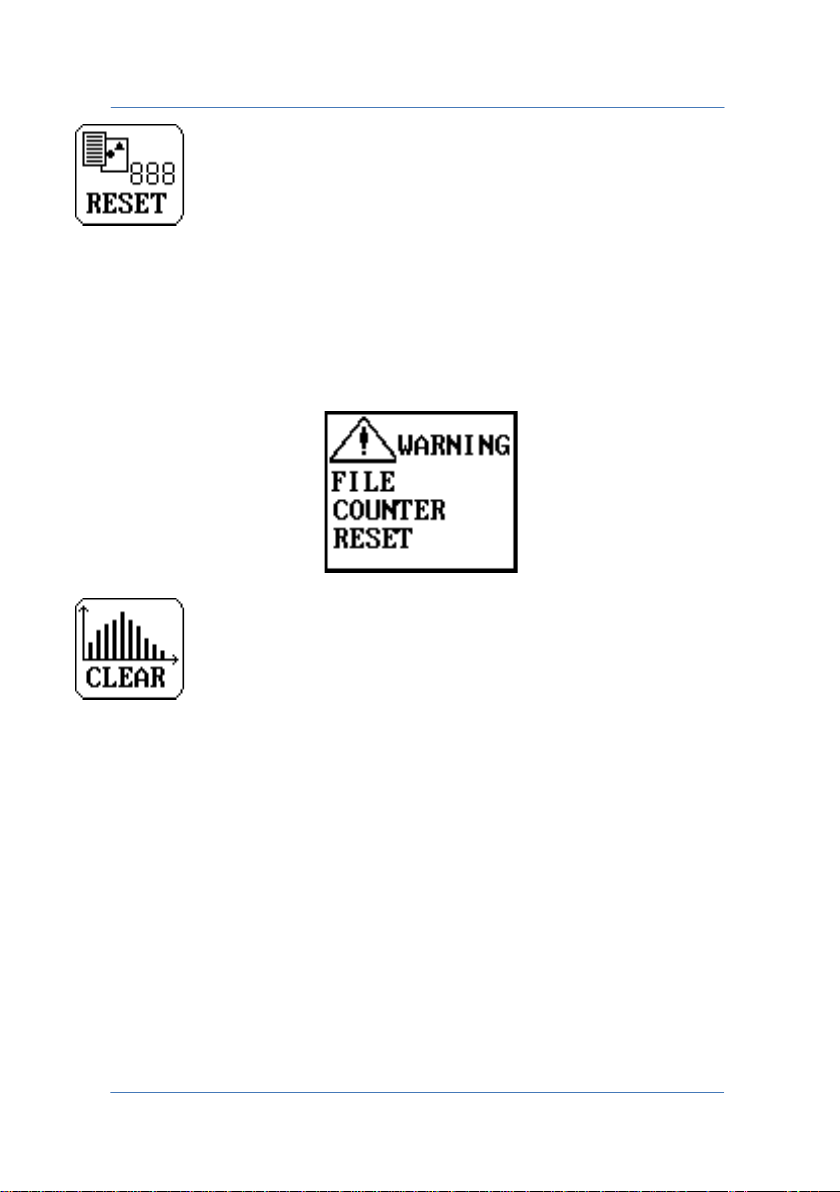
Reset counter for saving files.
Every file saved to pen-drive contains a progressive number to
facilitate subsequent identification; pressing the key resets the
progressive number to its default value "0" and displays the following
message.
Clears the spots internal memory.
Clears the internal memory in which the weld spots are stored. It must
be cleared every time a new measurement campaign is begun or when
switching from NORMAL to ADVANCED statistics mode and vice versa.
The instrument memory can store up to 20000 spots. When the weld
spots memory is full, it deletes automatically. The following message is
displayed when the key is pressed.
PAGE 40
Page 41
TECNA WELD TESTER TE1700
Saves the measurement graph to a pen-drive; the graph is saved as a
bitmap image in 320x240 format. The saved image is visible in the
MEASUREMENT GRAPH menu; the quantities selected in the menu are
consequently saved.
4.1 MEASUREMENT GRAPH CONFIGURATION
Saves to pen-drive a .CSV (Comma-Separated Values) file containing
numeric data relating to the quantities acquired, the configuration of
the instrument used, the transducers connected and the sequence of
numeric values acquired during the process that describe the time
trend of the quantities.
PAGE 41
Page 42
TECNA WELD TESTER TE1700
The device exports weld spots statistics from the pen-drive's internal
memory, if used. The quantity and type of saved data change,
depending on whether the NORMAL or ADVANCED statistics mode is
used. In both cases, a .CSV (Comma-Separated Values) file is saved
containing the numeric values of each spot relating to the quantities
measured and the instrument configuration. In ADVANCED mode, in
addition to data described above, an additional .CSV file is created, for
each weld spot, containing the numeric values describing the time
trend of the quantities acquired in a single welding spot.
WARNING: saving data in ADVANCED mode and a high number of
spots can take a long time.
The following icon appears during data saving.
WARNING: Do not remove the pen-drive during data writing
operations; just wait until the icon disappears. If you remove the pendrive before the write operations are over, stored data may be lost.
PAGE 42
Page 43
TECNA WELD TESTER TE1700
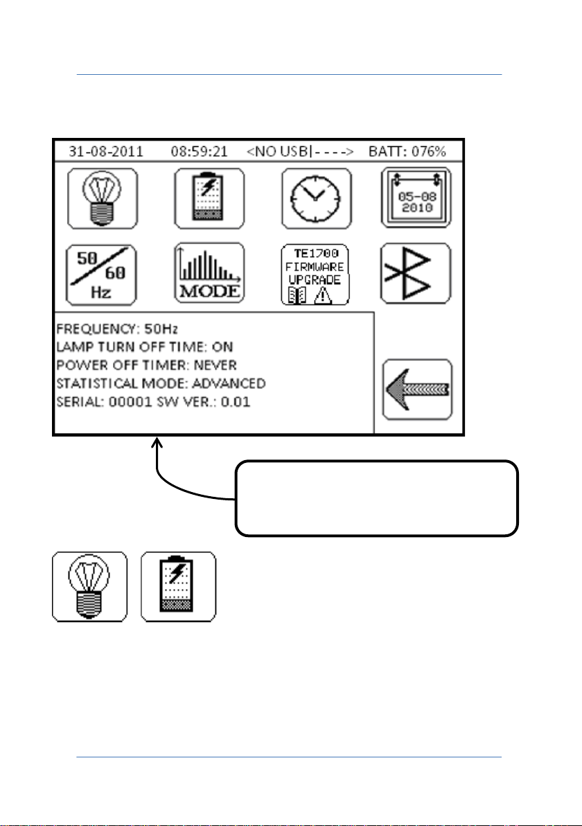
5.0 INSTRUMENT CONFIGURATION MENU
Summary of current instrument
configuration.
Screen lighting shutdown time and instrument shutdown time.
PAGE 43
Page 44
TECNA WELD TESTER TE1700
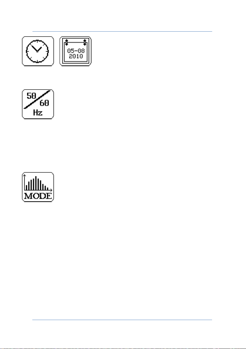
Current date and time.
For setting the mains frequency on the site where the instrument is
taking measurements. Choose between 50 Hz and 60 Hz. The value of
this parameter affects the measurements made on AC current
generators.
Allows you to select which statistical data the instrument must store
for each acquired spot. If NORMAL mode was selected, only spots
numeric data will be saved but if you selected ADVANCED mode, then
the numeric data and the waveforms associated with each spot will be
saved. When switching between the two modes, the instrument's
memory must be cleared.
WARNING: If using the ADVANCED mode, the acquisition rate
decreases to minimum, due to the greater amount of data to be
processed.
PAGE 44
Page 45
TECNA WELD TESTER TE1700
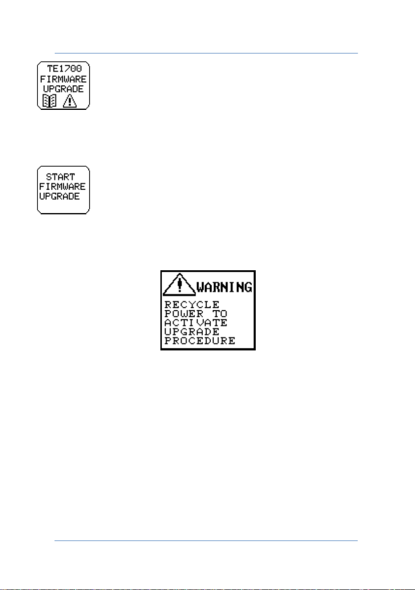
Allows you to access the firmware upgrade screen, which has the
following key in the foreground.
Pressing this key sets the instrument to firmware upgrade mode and
the following message appears.
If pressed by accident, simply switch off the instrument, switch it back
on again (nothing shows on the display), switch off and switch back on
again.
Once the firmware upgrade is started, the pairing with a compatible
Bluetooth device (PC, Android) is deleted. Simply pair the Bluetooth
device to the TE1700 again.
PAGE 45
Page 46
TECNA WELD TESTER TE1700
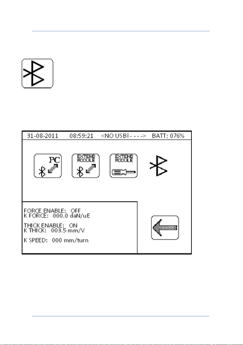
5.1 BLUETOOTH CONFIGURATION MENU
For accessing the screen that enables the instrument to be paired with
compatible Bluetooth devices and the optional TECNA TE1710
Expander to be set up, if available.
PAGE 46
Page 47
TECNA WELD TESTER TE1700
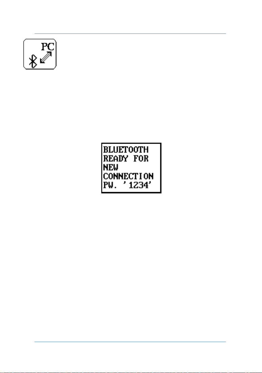
PC-BLUETOOTH - The key makes the TE1700 visible and pairable with a
compatible Bluetooth device (PC, Android). Each time the key is
pressed, a previous pairing is deleted, so the TE1700 can be paired
with only one device at a time.
The following message appears when the key is pressed.
The instrument can now be detected by an external device.
If the device being paired has a Bluetooth v2.1 module or better, no
code will be requested during the pairing.
Vice versa, if the Bluetooth device being paired has a Bluetooth v2.0
module or less, the default password "1234" will be requested.
Once pairing is complete, the message will clear automatically and the
TE1700 will be ready for connection.
PAGE 47
Page 48
TECNA WELD TESTER TE1700
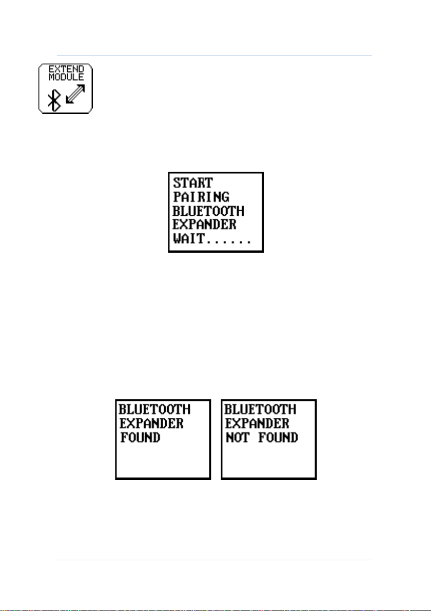
EXPANDER-BLUETOOTH - For pairing the TE1700 to the TE1710
Expander. The message appears when the key is pressed.
Before you start the pairing procedure, be sure the expansion card is
powered and within the range of the Bluetooth connection.
If pairing was successful, the instrument displays message EXPANDER
FOUND.
If pairing was unsuccessful, the instrument displays message
EXPANDER NOT FOUND.
PAGE 48
Page 49
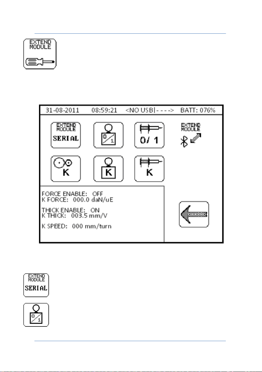
TECNA WELD TESTER TE1700
Selects the serial number of the TE1710 Expander to which
Activates/Deactivates the deformation sensor.
For accessing the configuration menu of the TE1710 Expander, if
available.
you are going to connect.
PAGE 49
Page 50
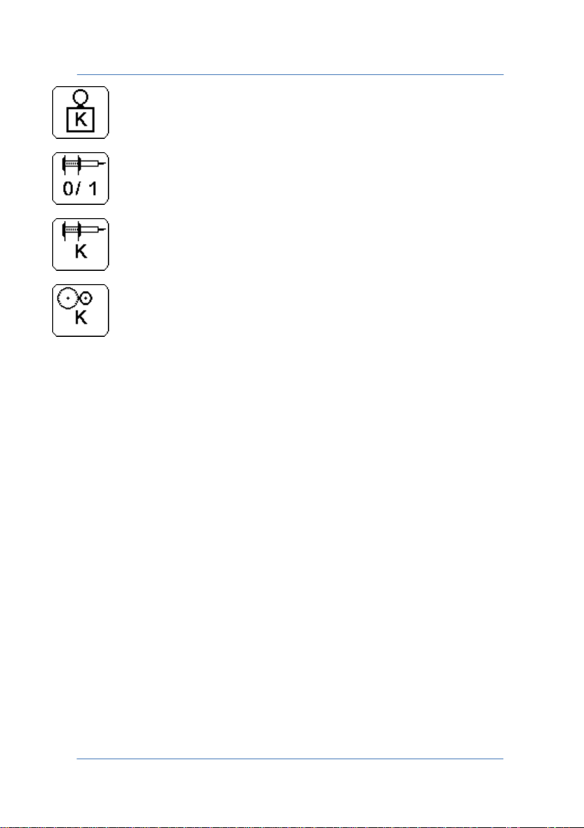
TECNA WELD TESTER TE1700
Sets the resolution of the deformation sensor.
Activates/Deactivates the position sensor.
Sets the resolution of the position sensor.
Sets the resolution of the speed sensor.
6.0 CONNECTING THE INSTRUMENT TO THE PC
In order to program the instrument remotely, you must pair the
TE1700 with a compatible Bluetooth device, such as a PC. Later on you
will be able to configure the instrument remotely through a terminal
emulator.
Proceed as follows to pair the TE1700 in Microsoft® Windows 7.
PAGE 50
Page 51
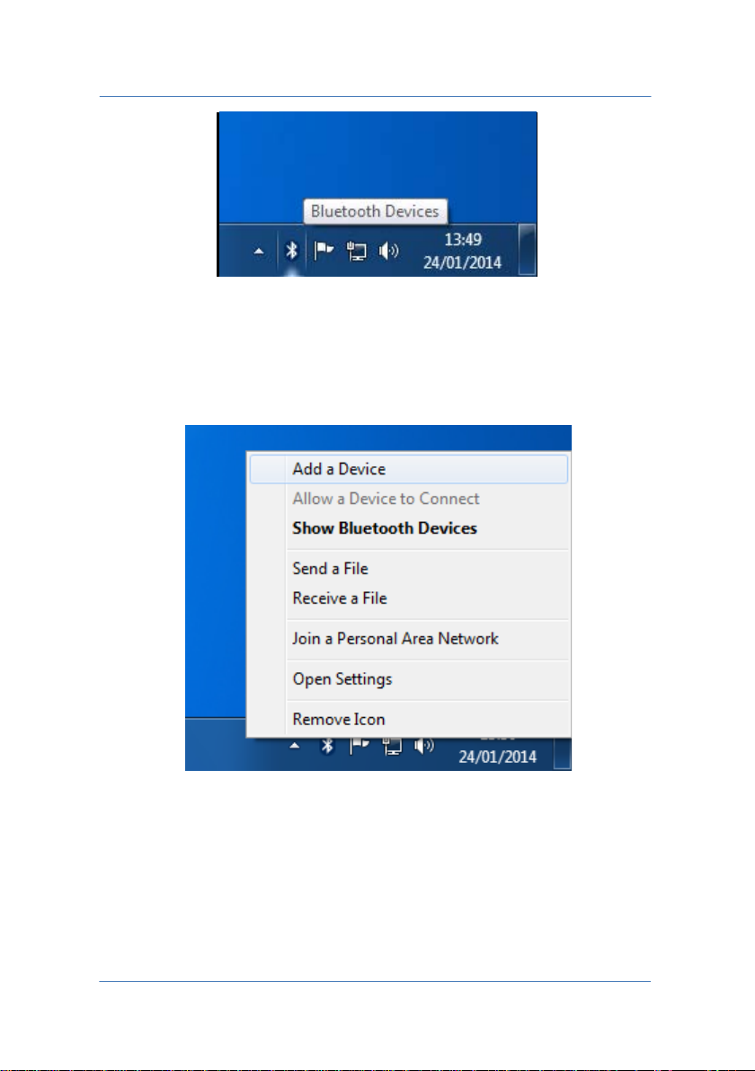
TECNA WELD TESTER TE1700
The Bluetooth icon is at the bottom right on the taskbar; a menu will
open when you click it with the right mouse button.
Select "Add a Device" in this menu to add a new Bluetooth device.
PAGE 51
Page 52
TECNA WELD TESTER TE1700
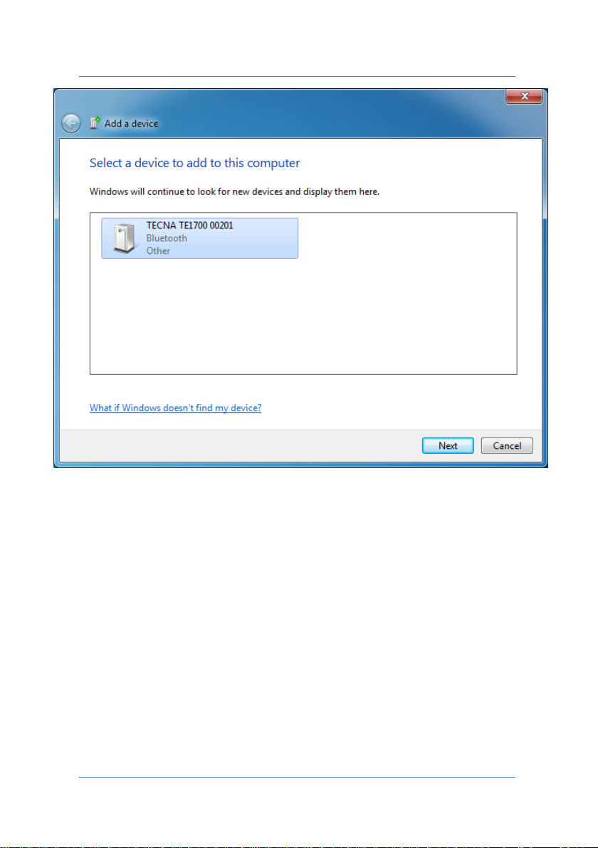
The screen shows the Bluetooth devices detected by the PC. To make it
possible to detect the TE1700, press the PC-BLUETOOTH key, shown in
paragraph 5.1.
The TE1700 can now be detected by the PC and should appear in the
window with the name "TECNA TE1700 12345", where 12345 is the
serial number of the device.
PAGE 52
Page 53
TECNA WELD TESTER TE1700
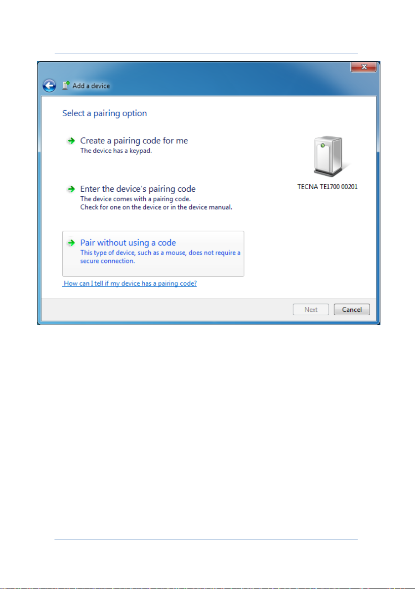
As indicated in paragraph 5.1, you need not enter any pairing code in
the TE1700 if the PC is equipped with a Bluetooth v2.1 module or
higher.
Then select "Pair without using a code" to pair without entering any
codes.
PAGE 53
Page 54
TECNA WELD TESTER TE1700
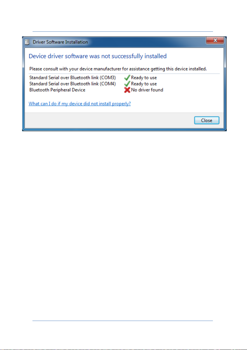
Once you have completed the pairing procedure, drivers are installed
automatically. The drivers used by the TE1700 are in Windows® by
default.
WARNING: Windows might detect a "Bluetooth Peripheral Device"
without drivers "No driver found". This is not important since the error
is caused by the presence of a Bluetooth profile that is not recognized
in Windows®.
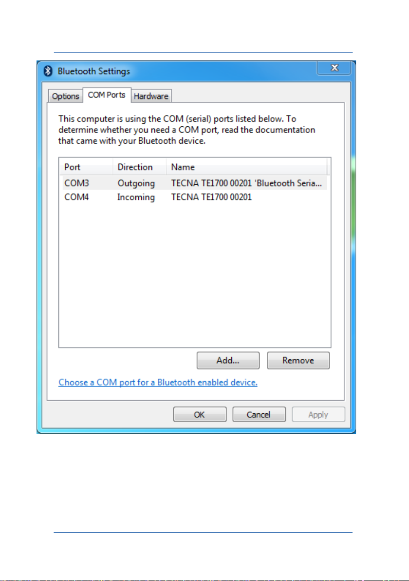
The installation was successful; now you need to locate which of the
two COM ports is used for Bluetooth connections at output.
By clicking on the Bluetooth icon at the bottom right in the taskbar,
select "Open settings" to open Bluetooth settings.
PAGE 54
Page 55
TECNA WELD TESTER TE1700
In the window that appears, you will notice that the port to be used is
COM3 since the indicated "Direction" is "Outgoing".
PAGE 55
Page 56

TECNA WELD TESTER TE1700
Now you can use a terminal emulator to connect to the COM port. A
terminal emulator for Windows is Putty©, a third party program
distributed under MIT license.
Putty© software is available inside the pen-drive distributed with the
Tecna TE1700 Weld Tester. In case of difficulty in finding the software,
contact your dealer.
PAGE 56
Page 57
TECNA WELD TESTER TE1700
6.1 PUTTY© TERMINAL EMULATOR
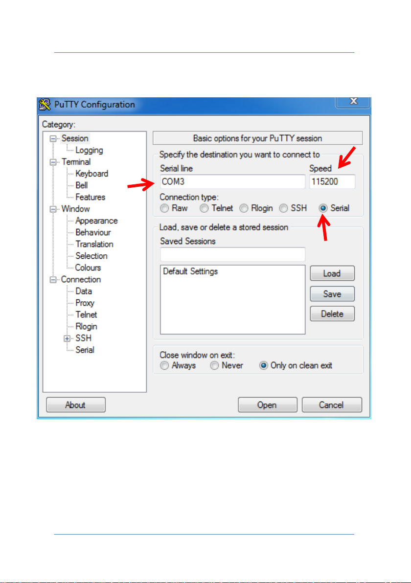
In order to connect with the terminal emulator, you must set:
• Connection type: Serial
• Serial line: outgoing serial port (e.g.: COM3)
• Speed: 115200
Press "Open" to open the connection.
PAGE 57
Page 58
TECNA WELD TESTER TE1700
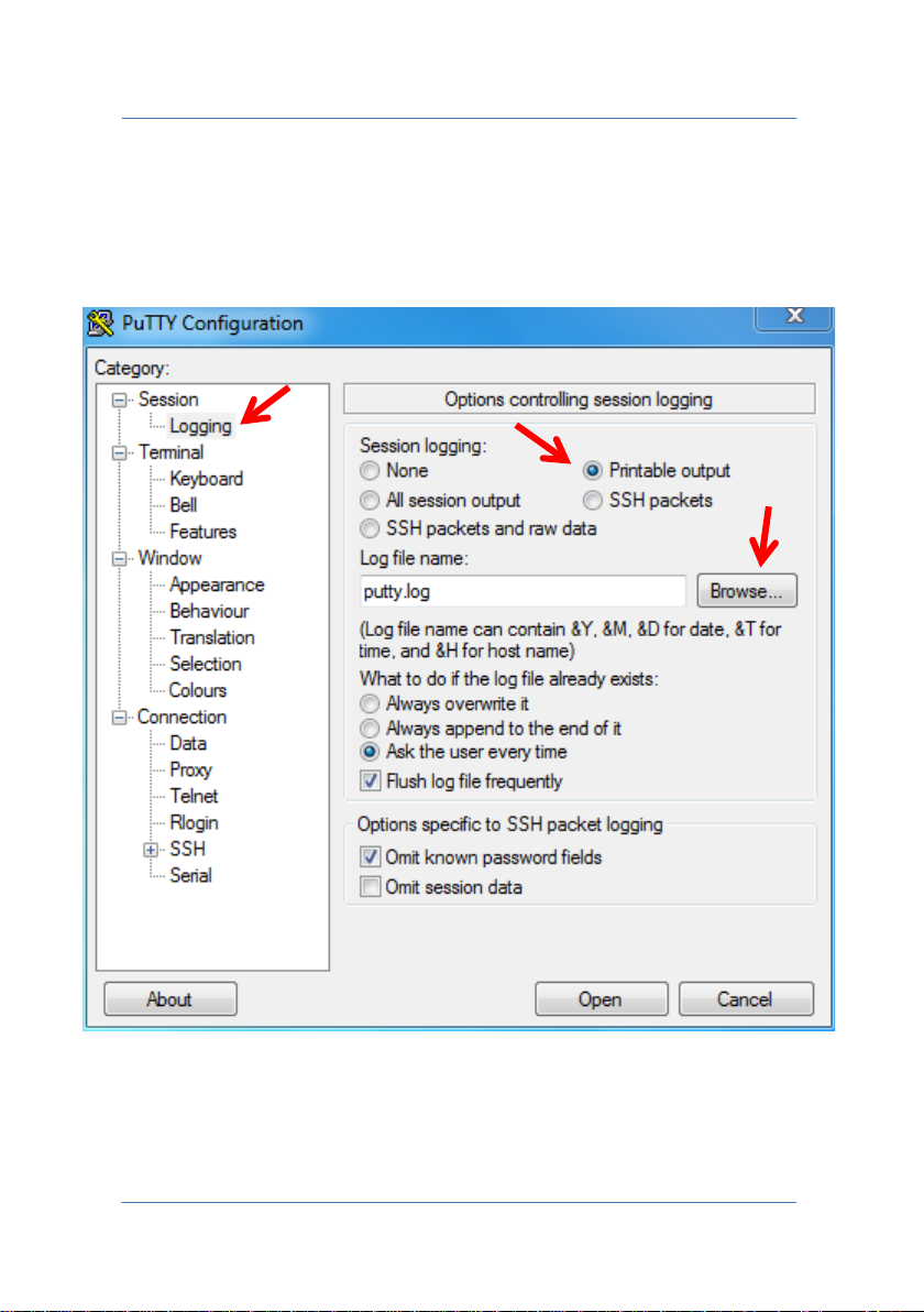
If you want to save data received from the terminal emulator to a disk,
go to the "Logging" menu and set parameter "Session logging" in
"Printable output". Use the "Browse…" key to select the path in which
to save the log file.
PAGE 58
Page 59
TECNA WELD TESTER TE1700
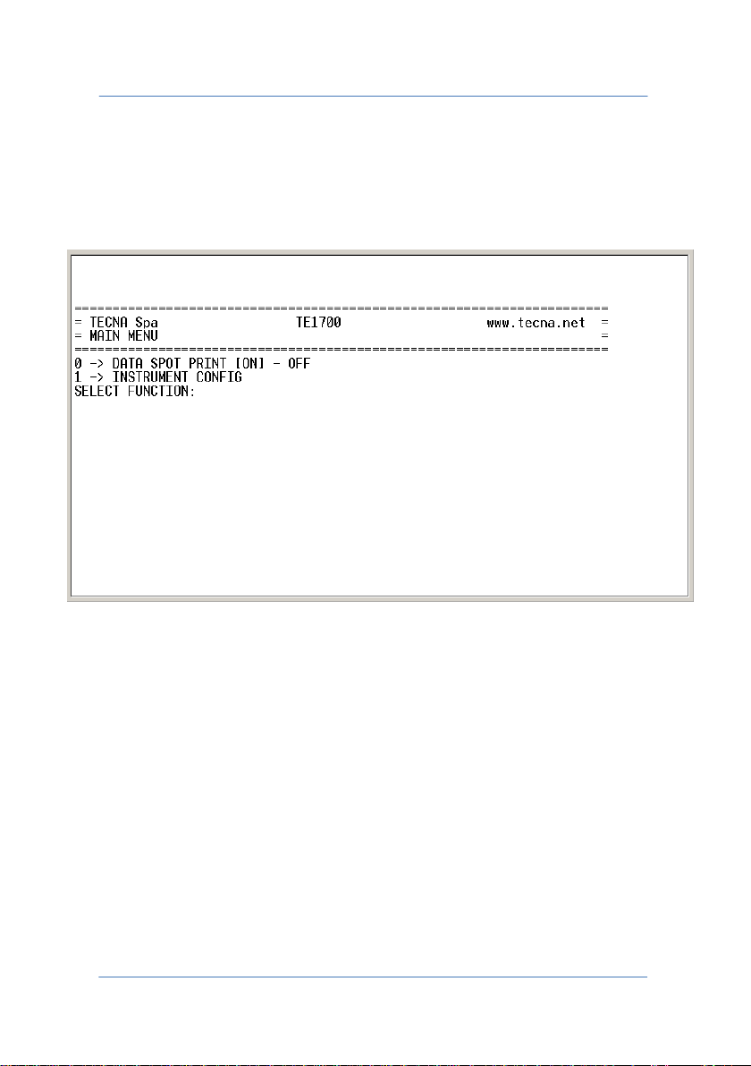
6.1.1 MAIN MENU
Main navigation menu enabling activation of the "DATA SPOT PRINT"
function and access to the "INSTRUMENT CONFIG" menu.
0 DATA SPOT PRINT: Activates\Deactivates printing of the
measurements performed.
1 INSTRUMENT CONFIG: Enables access to the instrument
configuration menu.
PAGE 59
Page 60
TECNA WELD TESTER TE1700
6.1.2 DATA SPOT PRINT
If the function is active, all the measurements performed will be
printed on the terminal, in green or red if the measurement is inside or
outside limits, and in black if the limits check is not active.
SPOT: 02864 07-11-2013 16:09:17
LIMIT MASK NUMBER: 01 LIMIT MASK EVAL RESULT: LIMIT OK
WELDING TIME: 003.0 CYCLES CONDUCTION DEG: 118
RMS CURRENT: 0004.70 kA
POSITIVE PEAK: 0007.58 kA NEGATIVE PEAK: 0008.25 kA
SECONDARY RMS VOLTAGE: 00.27V
SECONDARY POSITIVE PEAK: 00.46V SECONDARY NEGATIVE PEAK: 00.48V
ENERGY: 00071 J POWER MEAN: 001.26kW
SPOT: 02865 07-11-2013 16:09:50
LIMIT MASK NUMBER: 01 LIMIT MASK EVAL RESULT: NO LIMIT ACTIVE
WELDING TIME: 003.0 CYCLES CONDUCTION DEG: 118
RMS CURRENT: 0004.72 kA
POSITIVE PEAK: 0007.49 kA NEGATIVE PEAK: 0008.23 kA
SECONDARY RMS VOLTAGE: 00.27V
SECONDARY POSITIVE PEAK: 00.46V SECONDARY NEGATIVE PEAK: 00.48V
ENERGY: 00070 J POWER MEAN: 001.27kW
PAGE 60
Page 61

TECNA WELD TESTER TE1700
SPOT: 02866 07-11-2013 16:11:51
LIMIT MASK NUMBER: 01 LIMIT MASK EVAL RESULT: CURRENT OUT LIMIT
WELDING TIME: 003.0 CYCLES CONDUCTION DEG: 118
RMS CURRENT: 0004.69 kA
POSITIVE PEAK: 0007.48 kA NEGATIVE PEAK: 0008.21 kA
SECONDARY RMS VOLTAGE: 00.27V
SECONDARY POSITIVE PEAK: 00.46V SECONDARY NEGATIVE PEAK: 00.48V
ENERGY: 00070 J POWER MEAN: 001.26kW
PAGE 61
Page 62
TECNA WELD TESTER TE1700
6.1.3 INSTRUMENT CONFIG MENU
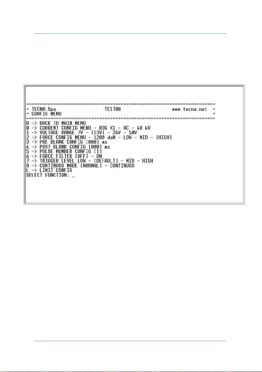
Instrument configuration menu.
The numbers and letters on the left of the arrow "" are the keys to
be pressed on the terminal to perform an action on the element
indicated to the right of the same arrow.
B BACK TO MAIN MENU: Returns to the main menu
0 CURRENT CONFIG MENU: Allows access to the current probe
configuration menu.
1 VOLTAGE RANGE: For setting the voltage rate 7V, 13V, 26V or
50V.
PAGE 62
Page 63

TECNA WELD TESTER TE1700
2 FORCE CONFIG MENU: For setting the force rate LOW, MID or
HIGH (i.e. 240 daN, 480 daN or 1,200 daN).
3 PRE BLANK CONFIG: For setting the PRE BLANK time in
milliseconds. Between 0 and 200 ms.
4 POST BLANK CONFIG: For setting the POST BLANK time in
milliseconds. Between 0 and 200 ms.
5 PULSE NUMBER CONFIG: For setting the number of pulses.
Between 1 and 9.
6 FORCE FILTER: Activates\Deactivates the filter on the force
measurement signal.
7 TRIGGER LEVEL: For setting the trigger level on the signal.
8 CONTINUOUS MODE: For selecting the type of signal acquisition
NORMAL\CONTINUOUS.
L LIMIT CONFIG: For accessing the submenu for setting
measurement check limits.
PAGE 63
Page 64
TECNA WELD TESTER TE1700
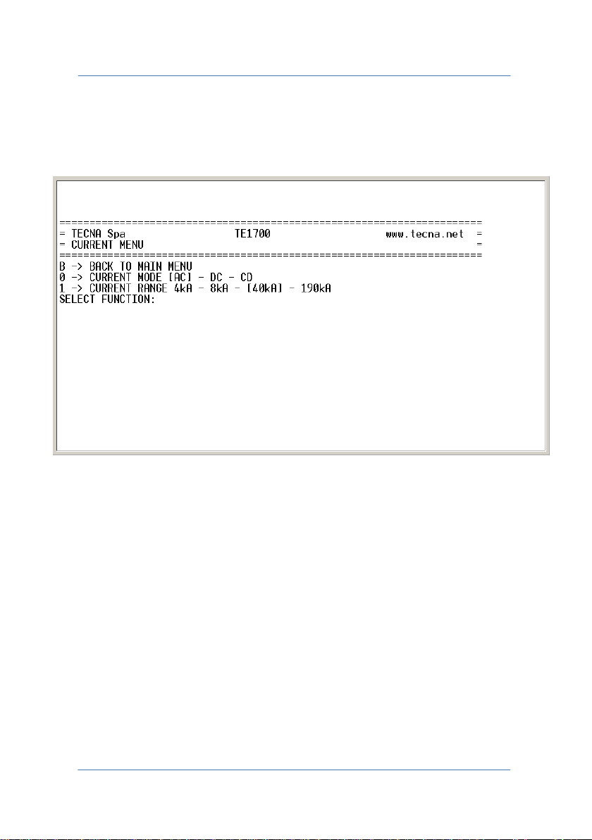
6.1.4 CURRENT CONFIG MENU
Current probe configuration menu.
B BACK TO MAIN MENU: Returns to the main menu.
0 CURRENT MODE: For selecting the amperometric source AC, DC or
CD for the current probe.
1 CURRENT RANGE: For selecting the amperometric rate 4kA, 8kA,
40kA or 190kA for the current probe currently inserted, in this case a
ROG x1.
PAGE 64
Page 65
TECNA WELD TESTER TE1700
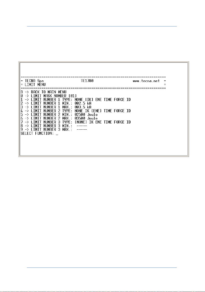
6.1.5 LIMIT CONFIG MENU
Measurement check limits configuration menu.
B BACK TO MAIN MENU: Returns to the main menu.
0 LIMIT MASK NUMBER: Represents the numeric identifier of the
check limits mask to be programmed or selected. Between 1 and 15
and can only be programmed remotely.
1 LIMIT NUMBER 1 TYPE: For selecting the type of control in IK, ENE,
TIME, FORCE or ID for the first mask limit.
2 LIMIT NUMBER 1 MIN: For setting the minimum value of the first
mask limit.
PAGE 65
Page 66

TECNA WELD TESTER TE1700
3 LIMIT NUMBER 1 MAX: For setting the maximum value of the first
mask limit.
4 LIMIT NUMBER 2 TYPE: For selecting the type of control in IK, ENE,
TIME, FORCE or ID for the second mask limit.
5 LIMIT NUMBER 2 MIN: For setting the minimum value of the
second mask limit.
6 LIMIT NUMBER 2 MAX: For setting the maximum value of the
second mask limit.
7 LIMIT NUMBER 3 TYPE: For selecting the type of control in IK, ENE,
TIME, FORCE or ID for the third mask limit.
8 LIMIT NUMBER 3 MIN: For setting the minimum value of the third
mask limit.
9 LIMIT NUMBER 3 MAX: For setting the maximum value of the third
mask limit.
WARNING: Two LIMIT NUMBER TYPE fields having the same quantity
cannot exist inside one mask.
PAGE 66
Page 67
TECNA WELD TESTER TE1700
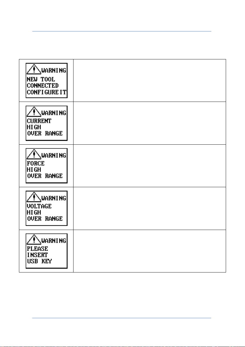
Signalling detection of a new transducer connected to
configured correctly before
Signalling input current over the selected rate. Switch to
Signalling input force over the selected rate. Switch to
Signalling input voltage over the selected rate. Switch to
An attempt was made to save a file to pen-drive but it
has not been inserted correctly or its format is not
drive is
7.0 ERROR MESSAGES
the instrument. It should be
use.
higher rate or use a transducer with lower sensitivity.
higher rate or use a transducer with lower sensitivity.
higher rate or use a transducer with lower sensitivity.
supported. Before saving the file, ensure the pencorrectly recognised.
PAGE 67
Page 68
TECNA WELD TESTER TE1700
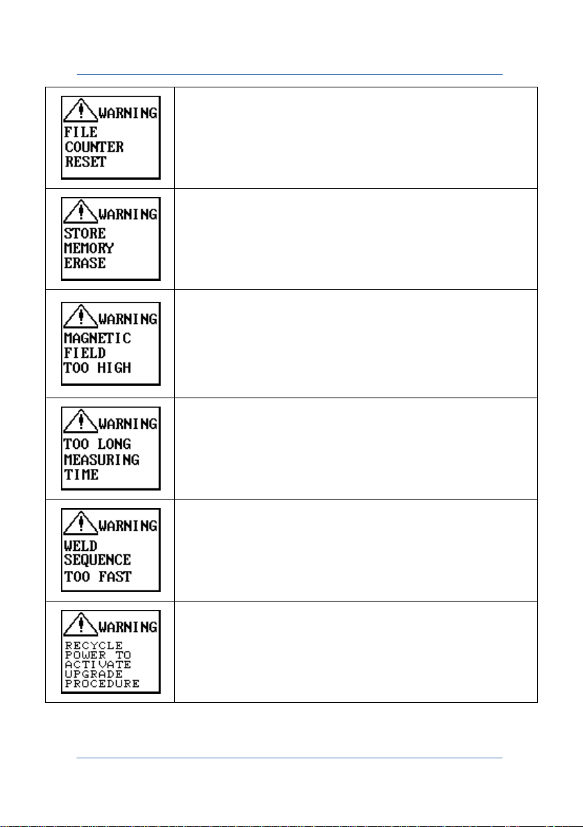
Signals that the progressive counter used to save the
drive was
Signals that the internal memory in which the spots to
The instrument is too near to the secondary area of the
spot welder and the magnetic field generated interferes
with the correct execution of the measurement. Move
the instrument away from the secondary circuit of the
Signals that the acquisition time of the measurement
process just performed was too long. It should be
Signals that the execution speed of the current welding
Signals that the instrument is running a firmware
.CSV (Comma-Separated Values) file to penreset.
be used for statistics are stored was cleared.
spot welder.
reduced.
spots is too high. Reduce the speed.
upgrade and needs to be switched off and back on.
PAGE 68
Page 69
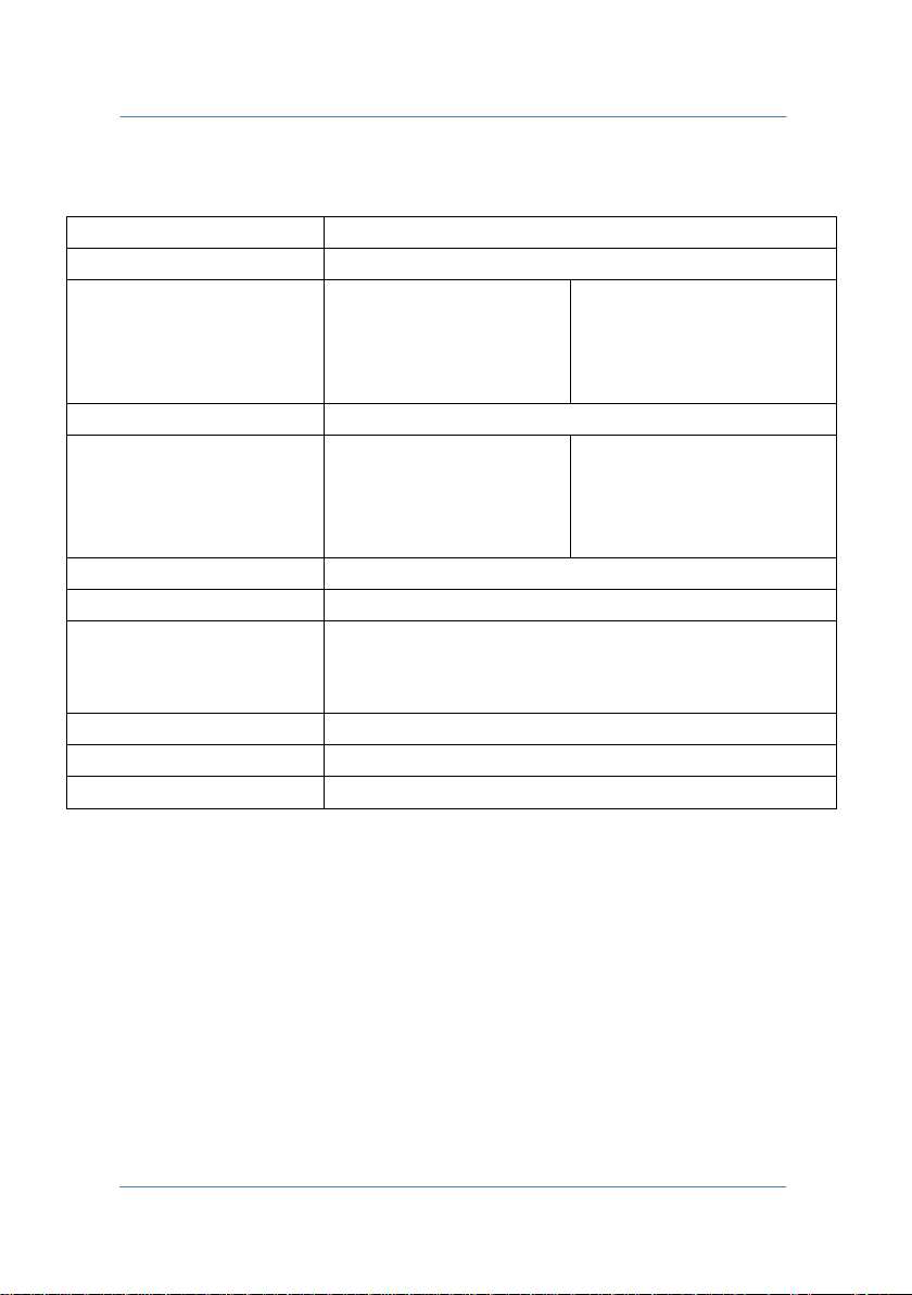
TECNA WELD TESTER TE1700
Dimensions (LxHxD)
180x115x45
Weight
0.7 Kg
Current ranges
1637 | Rogowsky 0.2X
20 KA, 40KA, 200KA, 950KA
Voltage ranges
7V, 13V, 26V, 50V | 1705
Force ranges
1661, 1673
Force cell 200 daN
RMS precision
Class 1
Time precision
1 ms (DC), 0.5 cycles (AC) or 0.1 ms (CD)
Battery performance
Rechargeable Ni-Mh Batteries with a performance of
Operating temperature
From 0°C to 40°C
Altitude
Up to 2,000 m
IP rating
IP40
8.0 INSTRUMENT FEATURES
All | Rogowsky 1X
N/A | Rogowsky 5X
N/A | Rogowsky 10X
1675
1662
1663
about 24 hours, depending on use. Recharged in 2
hours.
4KA, 8KA, 40KA, 190KA
800A, 1.6KA, 8KA, 38KA
400A, 800A, 4KA, 19KA
Force cell 1,200 daN
Force cell 2,000 daN
Force cell 10,000 daN
PAGE 69
Page 70
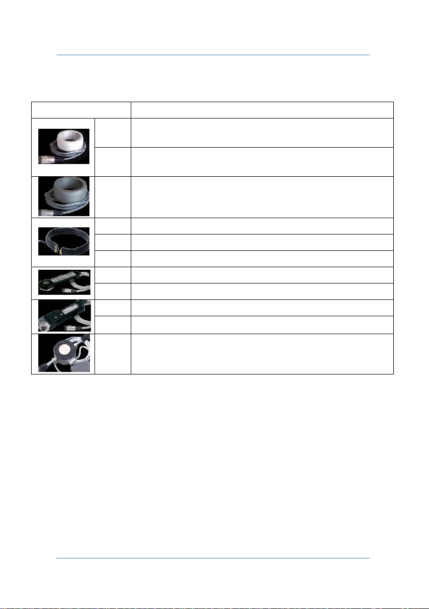
TECNA WELD TESTER TE1700
Item
Description
Rigid current transducer Ø min 32-36 max mm with cable
Rigid current transducer Ø min 40-45-46 max mm with cable
1635
Flexible transducer Ø 160 mm with cable L=2 m max
1636
Flexible transducer Ø 270 mm with cable L=2 m max
1637
Flexible transducer Ø 270 mm with cable L=2 m max
1661
Load cell from 200 daN 440 lb with cable L=2 m
1662
Load cell from 2,000 daN 4.400 lb with cable L=2 m
1673
Compact load cell from 200 daN 440 lb with cable L=2 m
1675
9.0 MEASURING ACCESSORIES
1631
1632
1633
L=2 m max
L=2 m max
Rigid current transducer Ø max 80 mm with cable L=2 m
max
Compact load cell from 1,200 daN 2.640 lb with cable L=2 m
1663
Load cell from 10,000 daN 22,000 lb with cable L=2 m
PAGE 70
Page 71

TECNA WELD TESTER TE1700
10.0 BATTERY REPLACEMENT AND PRODUCT
LIFE END
The TE1700 uses two batteries:
_ Buffer battery with Lithium Ions CR1220 – 3V
_ Nickel-Metal Hydride battery, 2400mAh – 7.2V (Tecna code 72790)
The estimated life of the buffer battery is 6 years but you still need to
replace it in the event that the product is unable to store date and
time correctly.
The Nickel-Metal Hydride battery's estimated life is 5 years, but you
still need to replace it if its operating performance is significantly
reduced.
WARNING: For safety reasons, you must disconnect all cables from the
TE1700 before replacing the batteries.
After setting the TE1700 to a safety state, you can unscrew the 6
screws at the back, those that join the two plastic shells.
WARNING: To avoid damaging the TE1700, you should remove the
Nickel-Metal Hydride battery before continuing.
You need not perform any other operation to change the Nickel-Metal
Hydride battery.
WARNING: It is advisable to wear work gloves when replacing the
buffer battery.
PAGE 71
Page 72
TECNA WELD TESTER TE1700
But if you want to change the buffer battery, remove the 4 screws that
secure the card to the front of the instrument. Use a tool made of nonconductive material, carefully remove buffer battery CR1220 from its
housing and replace it with a like battery available on the market.
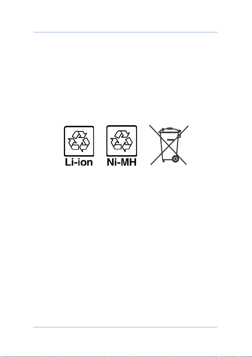
You may not dispose of the batteries by dumping them in the usual
waste bins. They must be disposed of properly through the WEEE
collection facilities in your country.
Also adhere to the following recommendations:
• Do not dispose of new or used batteries in fire
• Do not attempt to open the batteries
• Keep batteries out of children's reach
11.0 SAFETY OF USE
To avoid electric shock, always connect the instrument to ground.
Use the appropriate connector to ground the instrument.
PAGE 72
 Loading...