

TecMate Optimate 7 Ampmatic, TM254, TM255, Optimate 6 Ampmatic, TM180 EU Instructions For Use Manual
...Page 1
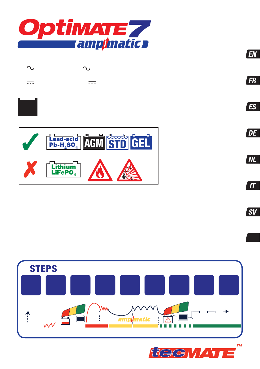
MODEL: TM254 / TM255
AC: 100 – 240V 50-60Hz
0.66A @ 240V / 1.59A @ 100V
DC: 120W ¨ 12V 10A
Thermally adjusted
INSTRUCTIONS FOR USE
IMPORTANT: Read completely
before charging
MODE D’EMPLOI
IMPORTANT: à lire avant
d’utiliser l’appareil
+-
1 x 12V
STD / AGM-MF / GEL
3 - 400Ah (max. Ah rating
based on 48 hour charge).
Automatic charger for 12V lead-acid batteries
Chargeur automatique pour batteries 12V plomb-acide
Cargador automático para baterías 12V plomoácido
Automatische Ladegerät für 12V Blei-Säure Batterien
Automatische lader voor 12V loodzuur accu’s
Caricabatterie automatico per batterie 12V piombo-acido
Automatisk diagnostisk laddare för 12V blybatterier
Automatick. nab.ječka pro 12V olovo/kyselinov. baterie
9
1
Low Volt
Start (0.5V)
2
Pulse
Wake up
3
TEST before
charge
4
SAVE
sulphated
battery
5
Pulse
SAVE
6
Controlled
CHARGE
MODO DE EMPLEO
IMPORTANTE: a leer antes de
utilizar el aparato
ANWENDUNGSVORSCHRIFTEN
WICHTIG: Vollständig vor der
Benutzung lesen
GEBRUIKSAANWIJZING
BELANGRIJK: Lees volledig voor
gebruik
ISTRUZIONI PER L’USO
IMPORTANTE: da leggere prima
di utilizzare l’apparecchio
INSTRUKTIONER
VIKTIGT: läs följande fullständiga
instruktioner för användningen
innan du använder laddaren
INSTRUKCE PRO POUŽIT.
DŮLEŽIT: Přečtěte si pozorně
před použit.m
7
OPTIMIZE
8
TEST after
CHARGE
9
OptiMate
‘365’
maintenance
CZ
2V
0.5V
0.5V
1.START 3.
TM254_TM255-IN1-170302
copyright @ 2016 TecMate International
2.
PULSE
TEST
14.4V
24-7-365
4&5.SAVE 6.CHARGE 7.OPTIMIZE 8.FINAL TEST 9.MAINTAIN
13.6V
Page 2
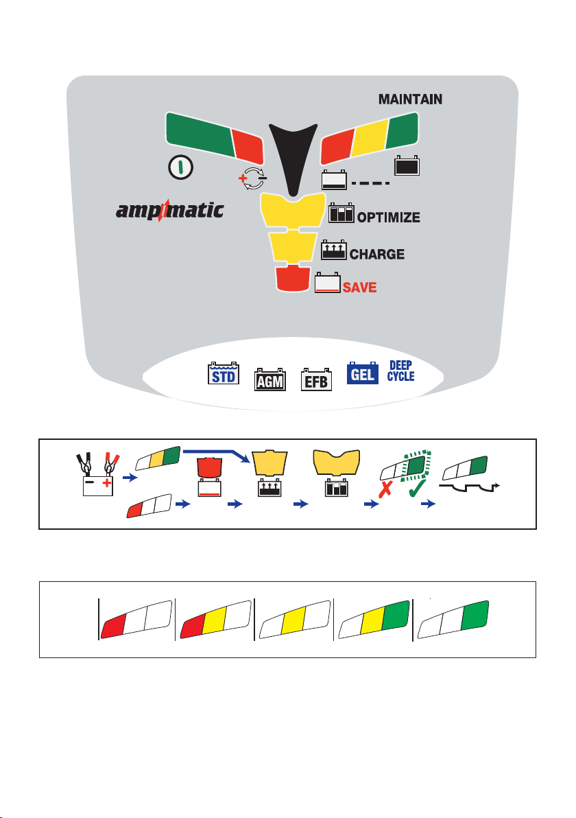
LEDs
CONNECT
TEST
10s
°t
1
SAVE
15m - 2h
2
12V
CHARGE
72h max
5
4
3
8
TEST
OPTIMIZE
10m - 36h
7
6
TEST
30m - 12h
MAINTAIN
365
TEST LEDs
0
0
80 100%604020AGM
7
8
8
7
6
7
100% 806040STD
6
Page 3
IMPORTANT SAFETY
INSTRUCTIONS FOR CANADA & USA
THIS PORTION OF THE MANUAL CONTAINS IMPORTANT SAFETY INSTRUCTIONS FOR
THE OPTIMATE 7 BATTERY CHARGER. IT IS OF THE UTMOST IMPORTANCE THAT
EACH TIME, BEFORE USING THE CHARGER, YOU READ AND EXACTLY FOLLOW THESE
INSTRUCTIONS. SAVE THESE INSTRUCTIONS.
Automatic charger for 12V lead-acid batteries
DO NOT USE FOR NiCd, NiMH, Li-Ion OR NON-RECHARGEABLE BATTERIES.
1. CAUTION : CLASS II APPLIANCE. DO NOT CONNECT TO GROUND.
2. Do not expose charger to rain or snow.
3. Use of an attachment not recommended or sold by the battery charger manufacturer may result in a risk of fire, electric shock,
or injury to persons.
4. To reduce risk of damage to electric plug and cord, pull by plug rather than cord when disconnecting charger.
5. An extension cord should not be used unless absolutely necessary. Use of improper extension cord could result
in a risk of fire and electric shock. If extension cord must be used make sure that :
a) pins on plug of extension cord are the same number, size and shape as those of plug on charger.
b) the extension cord is properly wired and in good electrical condition, and
c) the conductor wire size is large enough for the AC ampere rating of the charger as specified in the table below.
AC INPUT RATING IN AMPERES
Equal to or greater than But less than
2A 3A 25 (17.6)
6. Do not operate charger with damaged cord or plug – replace the cord or plug immediately.
7. Do not operate charger if it has received a sharp blow, been dropped,or otherwise damaged in any way;
take it to a qualified serviceman.
8. Do not disassemble charger; take it to a qualified serviceman when service or repair is required.
Incorrect reassembly may result in a risk of electric shock or fire.
9. To reduce risk of electric shock, unplug the charger from outlet before attempting any maintenance or cleaning.
Turning off controls will not reduce this risk.Clean only with slightly moist,not wet, cloth.Do not use solvents.
10. WARNING - RISK OF EXPLOSIVE GASES.
a) WORKING IN VICINITY OF A LEAD-ACID BATTERY IS DANGEROUS. BATTERIES GENERATE EXPLOSIVE GASES
DURING NORMAL BATTERY OPERATION. FOR THIS REASON, IT IS OF UTMOST IMPORTANCE THAT YOU FOLLOW THE
INSTRUCTIONS EACH TIME YOU USE THE CHARGER.
b) To reduce risk of battery explosion, follow these instructions and those published by the battery manufacturer
and manufacturer of any equipment you intend to use in vicinity of the battery. Review cautionary marking on
these products and on engine.
11. PERSONAL PRECAUTIONS.
a) Someone should be within range of your voice OR close enough to come to your aid when you work near a lead-acid battery.
b) Have plenty of fresh water and soap nearby in case battery acid contacts skin, clothing or eyes.
c) Wear complete eye protection and clothing protection. Avoid touching eyes while working near battery.
d) If battery acid contacts or enters eye, flood eye with cold running water for at least 10 minutes and get medical
attention immediately. If battery acid contacts skin or clothing, wash immediately with soap and water. If acid enters
an eye, immediately flood eye with running cold water for at least 10 minutes and get medical attention immediately.
e) NEVER smoke or allow a spark or flame in vicinity of battery or engine.
f) Be extra cautious to reduce risk of dropping a metal tool onto battery. It might spark or short-circuit battery or other electrical
part that may cause explosion.
g) Remove personal metal items such as rings, bracelets, necklaces, and watches when working with a lead-acid
battery. A lead-acid battery can produce a short-circuit current high enough to weld a ring or the like to metal,
causing a severe burn.
i) NEVER charge a frozen battery.
LENGTH OF CORD,
FEET (m)
50 (15.2)
100 (30.5)
AWG SIZE
OF CORD
18
18
14
SAFETY US & CAN
3
Page 4

12. PREPARING TO CHARGE
a) If necessary to remove battery from vehicle to charge,always remove grounded terminal from battery first.
Make sure all accessories in the vehicle are off, so as not to cause an arc.
b) Be sure area around battery is well ventilated while battery is being charged. Gas can be forcefully
blown away by using a piece of cardboard or other non-metallic material as a fan.
c) Clean battery terminals. Be careful to keep corrosion from coming in contact with eyes.
d) Add distilled water in each cell until battery acid reaches level specified by battery manufacturer. This helps purge
excessive gas from cells. Do not overfill. For a battery without cell caps, such as valve regulated lead acid (VRLA) or absorbed glass
mat (AGM) batteries, carefully follow manufacturer’s recharging instructions.
e) Study all battery manufacturer’s specific precautions such as removing or not removing cell caps while charging
and recommended rates of charge.
SAFETY US & CAN
Determine voltage of battery by referring to vehicle or battery user’s manual and BEFORE MAKING
f)
THE BATTERY CONNECTIONS, MAKE SURE THAT THE VOLTAGE OF THE BATTERY YOU ARE GOING TO
CHARGE MATCHES THE OUTPUT VOLTAGE OF THE CHARGER.
13. CHARGER LOCATION.
a) Locate charger as far away from battery as DC cables permit.
b) Never place charger directly above batterv being charged; gases from battery will corrode and damage the charger.
c) Never allow battery acid to drip on charger when reading gravity or filling battery. Do not operate charger in a closed-in area or
restrict ventilation in any way.
d) Do not set a battery on top of charger. IMPORTANT : Place charger on a hard flat surface or mount onto a vertical surface. Do not
place on plastic, leather or textile surface.
14. DC CONNECTION PRECAUTIONS
a) Connect and disconnect DC output clips only after setting any charger switches to off position and removing AC
cord from electric outlet. Never allow clips to touch each other, however should this happen no damage will result to
the charger circuit & the automatic charging programme will just reset to «start».
b) Attach clips to battery and chassis as indicated in 15(e), 15(f), and 16(b) through 16(d).
NOTE : This battery charger has an automatic safety feature that will prevent it from operating if the
battery has been inversely connected.
disconnect the battery clips, then reconnect correctly according to the instructions below.
15. FOLLOW THESE STEPS WHEN BATTERY IS INSTALLED IN VEHICLE. A SPARK NEAR A BATTERY MAY CAUSE BATTERY
EXPLOSION. TO REDUCE RISK OF A SPARK NEAR BATTERY :
a) Position AC and DC cords so as to reduce risk of damage by hood, door or moving engine part.
b) Stay clear of fan -blades, belts,pulleys,and other parts that can cause injury to persons.
c) Check polarity of battery posts.POSITIVE (POS, P, +) battery post usually has larger diameter than NEGATIVE (NEG,
N,–) post.
d) Determine which post of battery is grounded (connected) to the chassis. If negative post is grounded to chassis
(as in most vehicles), see (e). If positive post is grounded to the chassis, see (f).
e) For negative-grounded vehicle, connect POSITIVE (RED) clip from battery charger to POSITIVE (POS, P, + )
ungrounded post of battery. Connect NEGATIVE (BLACK) clip to vehicle chassis or engine block away from battery.
Do not connect clip to carburetor, fuel lines, or sheet-metal body parts. Connect to a heavy gage metal part of the
frame or engine block.
f) For positive-grounded vehicle, connect NEGATIVE (BLACK) clip from battery charger to NEGATIVE (NEG. N , -)
ungrounded post of battery. Connect POSITIVE (RED) clip to vehicle chassis or engine block away from battery.
Do not connect clip to carburetor, fuel lines, or sheet-metal body parts. Connect to a heavy gage metal part of the
frame or engine block.
g) When disconnecting charger, turn switches to off, disconnect AC cord,remove clip from vehicle chassis,and then
remove clip from battery terminal.
h) See operating instructions for length of charge information.
16. FOLLOW THESE STEPS WHEN BATTERY IS OUTSIDE VEHICLE. A SPARK NEAR THE BATTERY MAY CAUSE BATTERY
EXPLOSION. TO REDUCE RISK OF A SPARK NEAR BATTERY :
a) Check polarity of battery posts. POSITIVE (POS, P, +) battery post usually has a larger diameter than NEGATIVE
(NEG,N, -) post.
This battery charger has an automatic safety feature that will prevent it from operating if the
b)
Set charger switches to off position and/or remove AC cord from electrical outlet,
battery has been inversely connected. The charger does not allow charge current unless a voltage of
at least 2V is sensed.
c) Connect POSITIVE (RED) charger clip to POSITIVE (POS, P, +) post of battery.
d) Connect NEGATIVE (BLACK) charger clip to NEGATIVE (NEG, N, -) battery post of the battery.
e) Do not face battery when making final connection.
f) When disconnecting charger, always do so in reverse sequence of connecting procedure & break first connection
while as far away from battery as practical.
g) A marine (boat) battery must be removed & charged on shore. To charge it on board requires equipment specially
designed for marine use.
4
Page 5
AUTOMATIC DIAGNOSTIC CHARGER FOR 12V LEAD-ACID BATTERIES.
DO NOT USE FOR NiCd, NiMH, Li-Ion OR NON-RECHARGEABLE BATTERIES.
IMPORTANT: READ THE FOLLOWING INSTRUCTIONS BEFORE USING THE CHARGER
This appliance can be used by children aged from 8 years and above and persons with reduced
physical,sensory or mental capabilities or lack of experience and knowledge if they have been given
supervision or instruction concerning use of the appliance in a safe way and understand the hazards
involved. Children shall not play with the appliance. Cleaning and user maintenance shall not be made
by children without supervision.
SAFETY WARNING AND NOTES: Batteries emit EXPLOSIVE GASES - prevent flame or sparks near batteries. Disconnect
AC power supply before making or breaking DC/battery connections. Battery acid is highly corrosive. Wear protective clothing and
eyewear and avoid contact. In case of accidental contact, wash immediately with soap and water. Check that the battery posts are
not loose; if so, have the battery professionally assessed. If the battery posts are corroded, clean with a copper wire brush; if greasy
or dirty clean with a rag damped in detergent.
are in good, undamaged condition. If the input cable is damaged, it is essential to have it replaced
without delay by the manufacturer, his authorised service agent or a qualified workshop, to avoid
Protect your charger from acid and acid fumes and from damp and humid conditions both during use and in storage.
danger.
Damage resulting from corrosion, oxidation or internal electrical short-circuiting is not covered by warranty. Distance the charger
from the battery during charging to avoid contamination by or exposure to acid or acidic vapours. If using it in the horizontal
orientation, place the charger on a hard, flat surface, but NOT on plastic, textile or leather. Use the fixing holes provided in the
enclosure base to attach the charger to any convenient, sound vertical surface.
EXPOSURE TO LIQUIDS: This charger is designed to withstand exposure to liquids accidentally spilled or splashed onto the
casing from above, or to light rainfall. Prolonged exposure to falling rain is inadvisable and longer service life will be obtained by
minimizing such exposure.Failure of the charger due to oxidation resulting from the eventual penetration of liquid into the electronic
components, connectors or plugs,is not covered by warranty.
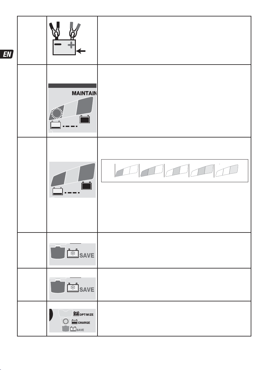
CONNECTING THE CHARGER TO THE BATTERY
1. Disconnect AC power supply before making or breaking DC / battery connections.
2. If charging a battery in the vehicle with the battery clips, before making connections, first check that the battery clips can be
safely and securely positioned clear from surrounding wiring, metal tubing or the chassis. Make connections in the following
First connect to the battery terminal not connected to the chassis (normally positive), then
order:
connect the other battery clip (normally negative) to the chassis well away from the battery and
fuel line. Always disconnect in reverse sequence.
3. When charging a battery out of the vehicle with the battery clips, place it in a well ventilated area. Connect the charger to the
battery: RED clamp to POSITIVE (POS, P or +) terminal and BLACK clamp to NEGATIVE (NEG, N or –) terminal. Make sure the
connections are firm and secure. Good contact is important.
4. If the battery is deeply discharged (and possibly sulphated), remove from the vehicle and inspect the battery before
connecting the charger for a recovery attempt. Visually check the battery for mechanical defects such as a bulging or
cracked casing, or signs of electrolyte leakage. If the battery has filler caps and the plates within the cells can be seen from the
outside, examine the battery carefully to try to determine if any cells seem different to the others (for example, with white
matter between the plates, plates touching). If mechanical defects are apparent do not attempt to charge the battery, have the
battery professionally assessed.
5. If the battery is new, before connecting the charger read the battery manufacturer’s safety and operational instructions
carefully. If applicable, carefully and exactly follow acid filling instructions.
PROCEEDING TO CHARGE:
CHARGING TIME : Charge time on a flat but otherwise undamaged battery: a 100Ah 12V should take no more than about 12
hours to progress to the self-discharge check. Deep-discharged batteries may take significantly longer, a full charge may not be
achieved within the 72 hour charge safety limit. In this case.
: The charge voltage is inversely regulated according to ambient temperature i.e. voltage is increased at lower temperature,
decreased at higher temperature. Adjustment: -0.004V / cell / °C above or below 20°C (68°F).
POWER ON: LED #1 - Confirms AC power supply to the charger.
HIGH and LOW intensity indication: The"POWER ON" LED #1 will indicate brightly when current is delivered to the battery.
The "POWER ON" LED #1 will reduce intensity to a low level to indicate low power "ECO" mode. This will occur if there is no battery
connected, or when a battery is connected and the program finds itself in the voltage retention test mode or the 'rest' periods of
Maintenance Charge mode.
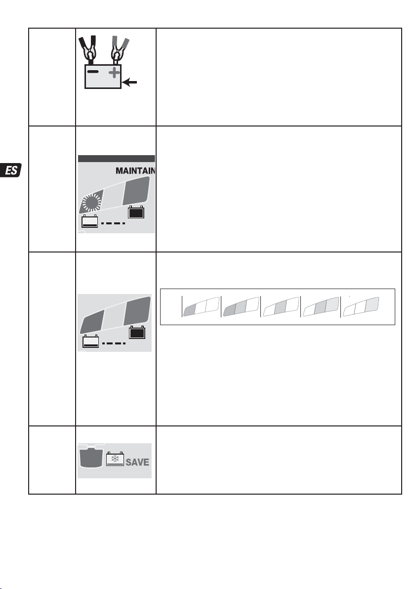
REVERSE POLARITY PROTECTION: LED #2 - Lights when the battery connections are incorrect. The charger is
protected so no damage will result, and the output will remain disabled until the connections are corrected.
Use the charger only if the input and output leads and connectors
electronically
SAFETY
5
Page 6
STEP 1
Low Volt
START -
Bat ≥ 0.5V
STEP 2
Pulse
wake up
STEP 3
TEST
before
charge
STEP 4
ADVANCED
SAVE
STEP 5
PULSE
SAVE
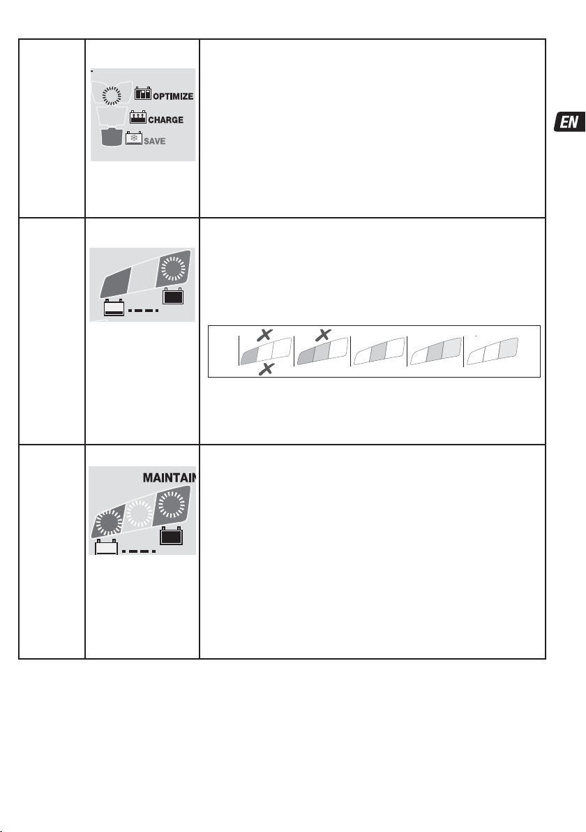
STEP 6
CHARGE
LED #8 FLASHING
7
8
TEST
TEST LEDs
6 : GREEN
7 : YELLOW
8 : RED
7
8
TEST
LED #3 : RED
3
LED #3 : RED
3
LED #4 : YELLOW
4
STD: Battery voltage check - OptiMate 7 Ampmatic automatically activates
if connected battery voltage is at least 0.5 Volt.
Batteries measuring below 2 Volts at connection will proceed to
STEP 2 for 'Pulse wake up' that includes a battery short circuit test.
V
Batteries measuring 2 Volts or more will proceed directly to STEP 3.
Pulse wake up - LED #8 (red) flashing: OptiMate 7 Ampmatic is injecting a
test signal to see if the battery is recoverable.
Once the voltage holds above 2 Volts and no short circuit has been detected the
program will commence to STEP 3.
If flashing continues the following conditions may prevent the charge program from
progressing:
1) Vehicle circuitry remains connected to the battery.
6
NOTE: If the battery under charge is in a low voltage or suphated state,
for the most effective charge and test results disconnect the battery
from the vehicle circuitry and then charge.
2) Battery has multiple short circuited cells. The battery has permanent damage and
should be replaced.
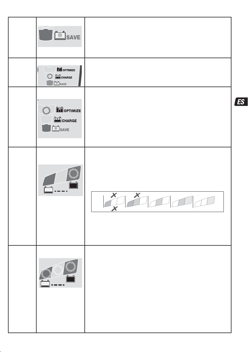
TEST LEDs #6/7/8 indicate the battery condition prior to charging. Consult the table
below to match TEST LED indication to an estimated state of charge percentage
(SOC%). Charging commences after 10 seconds.
0
6
Decisions made during the test:
Charge voltage during STEP 6 and 7 is adjusted according to the measured ambient
temperature.
STEP 7 OPTIMIZE minimum charge time is set according to the test result, varying
between 10 minutes for a battery with 80% or higher state of charge to 120 minutes for
a battery with 40% or less state of charge.
Severity of discharge is determined; a battery with 60% or more charge progresses
directly to STEP 6 where-as a severely discharged battery progresses to STEP 4 and 5.
Severely discharged batteries will undergo a longer test (up to 12 hours) during STEP 8.
Charge time: maximum 2 hours.
Output voltage increases to a maximum of 22V with current limited to 0.4A, but only if
no vehicle electronics have been detected, otherwise it moves directly to STEP 5.
IMPORTANT: Read section VERY FLAT NEGLECTED BATTERIES below.
CHARGE TIME : min 15 minutes, max. 2 hours.
Current is delivered in pulses to prepare the battery to accept normal charge.
This step is particularly effective for recovery of factory activated / “hi-performance”
pure lead or cyclic cell AGM batteries.
The ampmatic™ charge current monitoring and control program automatically
determines the most efficient rate of charge current for the connected battery,
according to its state of charge, state of health, and electrical storage capacity.
8
0
Engages if the battery was diagnosed as sulphated,
Engages if the battery state of charge was 40% or less OR
battery has sufficiently recovered during ADVANCED SAVE.
Engages if the battery state of charge was 50% or higher (as tested in
STEP 3) or once the battery has been sufficiently recovered during STEP 5.
7
8
unable to accept or hold charge.
7
6
7
80 100%604020AGM
6
100% 806040STD
6
Page 7
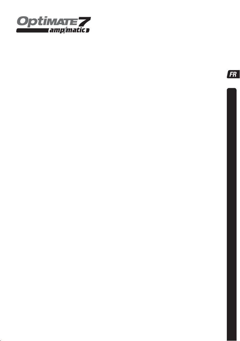
STEP 7
OPTIMIZE
STEP 8
TEST after
charge
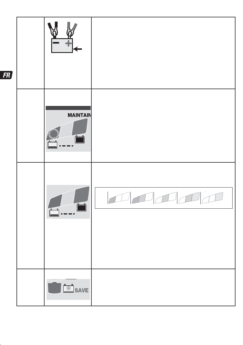
STEP 9
OPTIMATE
'365'
Maintenance
LED #5 : YELLOW
5
LED #6 FLASHING
6
TEST
LED #6 / 7 / 8 ON
6
7
8
TEST
For batteries with a good
state of health LED #6
(green) will remain on.
Exception: STD wet cell
batteries with filler caps
have a lower fully charged
voltage: LED #6 remains
on together with LED #7.
Engages when the voltage has reached 14.4V for the first time during
CHARGE mode.
The ampmatic™ current control program now delivers pulses of current to equalise
the individual cells within the battery and optimizes charge level.
Charging should complete within the minimum charge time set during STEP 3, but if
the battery requires further charging the program will extend OPTIMIZE mode up to a
maximum of 1/2 the charge time the battery remained in STEP 6.
NOTE: Charge time is usually extended if there is higher than expected current draw by
connected circuitry or battery health is less than optimal.
TIP: If the battery under charge was in a low voltage or suphated state, for the most
effective charge and test results disconnect the battery from the vehicle circuitry and
then charge.
For safety reasons there is an overall charge time limit of 72 hours for
STEP 4, 5 and 6.
TEST after charge : Delivery of current to the battery is interrupted for
30 minutes** to allow the program to determine the battery’s ability to
retain charge.
IF the result in STEP 3 was RED (LED #8) or RED & YELLOW (LED #7 & 8), indicating
**
a deep discharged battery) the voltage retention test is extended to 12 hours to confirm
battery health.
The TEST result (indicated on LED # 6, 7, 8) is adjusted in real time according to the
measured battery voltage.
0
7
8
0
The TEST will be interrupted if LED #8 (red) lights. A significant problem exists if the
battery is unable to retain sufficient charge during this voltage retention test. Consult
the table above to match TEST LED indication to an estimated state of charge
percentage (SOC%).
More information is provided in the section “NOTES ON TEST RESULTS”.
MAINTENANCE CHARGE: LED #6 / 7 / 8 steady on
Float voltage setting: 13.6V nominal at 20°C (68°F) The float voltage is inversely
regulated according to ambient temperature; i.e., voltage is increased at lower
temperature, decreased at higher temperature.
Adjustment: -0.004V / cell / °C above or below 20°C (68°F).
STD maintenance mode consists of 30 minute float charge periods followed by and
alternating with 30 minute ‘rest’ periods, during which there is no charge delivered.
This “50% duty cycle” prevents loss of electrolyte in sealed batteries and minimizes
gradual loss of water from the electrolyte in batteries with filler caps, and thereby
contributes significantly to optimizing the service life of irregularly or seasonally used
batteries.
During “float charge” a continuous LOW CURRENT PULSE IS DELIVERED TO PREVENT
SULFATION, further extending battery power and life.
If the OptiMate senses the battery has lost charge the program will revert back to
CHARGE step.
according to state of charge measured during STEP 8.
8
7
80 100%604020AGM
6
7
100% 806040STD
6
VERY FLAT NEGLECTED BATTERIES: If the battery is deeply discharged (and possibly sulfated), remove from the vehicle or
equipment and inspect the battery before connecting the charger for a recovery attempt.
The charger’s TURBO recovery mode cannot engage if it senses that the battery is still connected to a circuit which effectively
offers a lower electrical resistance than the battery on its own. However, if the deep-discharged battery is not removed for recovery, neither
battery nor vehicle or equipment electronics will be damaged. Pay particularly close attention to the following A battery left
deep-discharged for an extended period may develop permanent damage in one or more cells. Such batteries may heat up excessively
during high current charging.
Monitor the battery temperature during the first hour, then hourly there-after. Check for unusual signs, such as bubbling or leaking
electrolyte, heightened activity in one cell compared to others, or hissing sounds. If at any time the battery is uncomfortably hot to touch or
you notice any unusual signs, DISCONNECT THE CHARGER IMMEDIATELY.
7
Page 8

NOTES ON TEST RESULTS:
1. For any test result other than green #6 (or green #6 and yellow #7 together if the battery is a STD type with filler caps), disconnect
the battery from the electrical system it supports, and reconnect the OptiMate. If a better test result is now obtained, this suggests
that the power losses are partly due to an electrical problem in the electrical system and not in the battery itself. If the poor result
persists, you are advised to take the battery to a professional service workshop equipped with professional equipment for a more
thorough investigation.
If the red LED #8 alone, or the yellow #7 and red LED #8 indicate together (or yellow LED alone for a sealed battery), a significant
2.
problem exists. The red / yellow+red LEDs mean that after being charged the battery’s voltage is not being sustained or that despite
recovery attempts the battery was irrecoverable. This may be due to a defect in the battery itself, such as a short-circuited cell or
total sulphation, or, in the case of a battery still connected to the electrical system it supports, the red LED #8 may be signalling a
loss of current through deteriorated wiring or a degraded switch or contact, or in-circuit current-consuming accessories. A sudden
load being switched on while the charger is connected can also cause the battery voltage to dip significantly.
GOOD TEST RESULT, but the battery cannot deliver sufficient power: a) Permanent damage within the battery may be causing
3.
excessive self discharge that is not detected within the test period. Disconnect OptiMate from the battery. After at least 48 hours
reconnect and observe the result during the TEST BEFORE CHARGE. b) Long term vibration may have caused hairline cracks or poor
connections in inter cell connectors within the battery. A high loss of voltage occurs across such cracks or poor connections when
power demand is high (e.g. cranking the engine).
MAINTAINING A BATTERY FOR EXTENDED PERIODS: The OptiMate will maintain a battery whos basic condition is good,
for months at a time. At least once every two weeks, check that the connections between the charger and battery are secure, and,
in the case of batteries with filler caps on each cell, disconnect the battery from the charger, check the level of the electrolyte and if
necessary, top up the cells (with distilled water, NOT acid), then reconnect. When handling batteries or in their vicinity, always take
care to observe the SAFETY WARNINGS above.
ECO POWER SAVING MODE WHEN THE CHARGER IS CONNECTED TO AC SUPPLY:
The power converter switches to ECO mode when the charger is not connected to a battery resulting in a very low power draw of
less than 0.5W, equivalent to power consumption of 0.012 kWh per day. When a battery is connected to the charger power
consumption depends on the current demand of the battery and its connected vehicle / electronic circuitry. After the battery has
been charged and the charger is in long term maintenance charge mode (to keep the battery at 100% charge) the total power
consumption is estimated to be 0.024kWh or less per day.
LIMITED WARRANTY
TecMate (International) SA, B-3300 Tienen, Belgium, offers this limited warranty to the original purchaser at retail of this
product. This limited warranty is not transferable. TecMate (International) warrants this battery charger for three years from
date of purchase at retail against defective material or workmanship. If such should occur the unit will be repaired or replaced
at the option of the manufacturer. It is the obligation of the purchaser to forward the unit together with proof of purchase (see
NOTE), transportation or mailing costs prepaid, to the manufacturer or its authorized representative. This limited warranty is
void if the product is misused, subjected to careless handling, or repaired by anyone other than the factory or its authorized
representative. The manufacturer makes no warranty other than this limited warranty and expressly excludes any implied
warranty including any warranty for consequential damages.
THIS IS THE ONLY EXPRESS LIMITED WARRANTY AND THE MANUFACTURER NEITHER ASSUMES NOR AUTHORIZES ANYONE TO
ASSUME OR MAKE ANY OTHER OBLIGATION TOWARDS THE PRODUCT OTHER THAN THIS EXPRESS LIMITED WARRANTY. YOUR
STATUTORY RIGHTS ARE NOT AFFECTED.
NOTE: Details at www.tecmate.com/warranty.
OptiMate 7 and the names of other battery care products mentioned in these instructions such as BatteryMate, TestMateand
TestMate mini, are registered trademarks of TecMate International NV.
WARRANTY in Canada, USA, Central America and South America:
TecMate North America, Oakville, ON, Canada, as a wholy owned subsidiary of TecMate International, assumes the
responsibility for product warranty in these regions.
More information on TecMate products can be found at www.tecmate.com.
8
Page 9
INSTRUCTIONS IMPORTANTES CONCERNANT LA SÉCURITÉ
CONSERVER CES INSTRUCTIONS. CE MANUEL CONTIENT DES INSTRUCTIONS
IMPORTANTES CONCERNANT LA SÉCURITÉ ET LE FONCTIONNEMENT DU
CHARGEUR OPTIMATE 7.
CHARGEUR AUTOMATIQUE POUR BATTERIES 12V PLOMB-ACIDE
NE CONVIENT PAS POUR LES BATTERIES NiCd, NiMH, Li-Ion OU NON RECHARGEABLES.
AVERTISSEMENT :
N’utiliser l’appareil qu’à l’intérieur. Ne pas exposer à la pluie ou à la neige. Appareil de Classe II.
a) CONSERVER CES INSTRUCTIONS. CE MANUEL CONTIENT DES INSTRUCTIONS IMPORTANTES CONCERNANT LA SÉCURITÉ ET
LE FONCTIONNEMENT.
b) IL EST DANGEREUX DE TRAVAILLER A PROXIMITÉ D’UNE BATTERIE AU PLOMB. LES BATTERIES PRODUISENT DES GAZ
EXPLOSIFS EN SERVICE NORMAL. IL EST AUSSI IMPORTANT DE TOUJOURS RELIRE LES INSTRUCTIONS AVANT D’UTILISER LE
CHARGEUR ET DE LES SUIVRE À LA LETTRE.
c) POUR RÉDUIRE LE RISQUE D’EXPLOSION, LIRE CES INSTRUCTIONS ET CELLES QUI FIGURENT SUR LA BATTERIE.
d) NE JAMAIS FUMER PRÈS DE LA BATTERIE OU DU MOTEUR ET ÉVITER TOUTE ÉTINCELLE OU FLAMME NUE À PROXIMITÉ DE
CES DERNIERS.
e) UTILISER LE CHARGEUR POUR CHARGER UNE BATTERIE AU PLOMB UNIQUEMENT. CE CHARGEUR N’EST PAS CONÇU POUR
ALIMENTER UN RÉSEAU ÉLECTRIQUE TRÈS BASSE TENSION NI POUR CHARGER DES PILES SÈCHES. LE FAIT D’UTILISER LE
CHARGEUR POUR CHARGER DES PILES SÈCHES POURRAIT ENTRAÎNER L’ÉCLATEMENT DES PILES ET CAUSER DES BLESSURES
OU DES DOMMAGES.
f) NE JAMAIS CHARGER UNE BATTERIE GELÉE.
g) S’IL EST NÉCESSAIRE DE RETIRER LA BATTERIE DU VÉHICULE POUR LA CHARGER, TOUJOURS DÉBRANCHER LA BORNE DE
MISE À LA MASSE EN PREMIER. S’ASSURER QUE LE COURANT AUX ACCESSOIRES DU VÉHICULE EST COUPÉ AFIN D’ÉVITER LA
FORMATION D’UN ARC.
h) PRENDRE CONNAISSANCE DES MESURES DE PRÉCAUTION SPÉCIFIÉES PAR LE FABRICANT DE LA BATTERIE, P. EX., VÉRIFIER
S‘IL FAUT ENLEVER LES BOUCHONS DES CELLULES LORS DU CHARGEMENT DE LA BATTERIE, ET LES TAUX DE CHARGEMENT
RECOMMANDÉS.
i) SI LE CHARGEUR COMPORTE UN SÉLECTEUR DE TENSION DE SORTIE, CONSULTER LE MANUEL DE L’USAGER DE LA VOITURE
POUR DÉTERMINER LA TENSION DE LA BATTERIE ET POUR S’ASSURER QUE LA TENSION DE SORTIE EST APPROPRIÉE. SI LE
CHARGEUR N’EST PAS MUNI D’UN SÉLECTEUR, NE PAS UTILISER LE CHARGEUR À MOINS QUE LA TENSION DE LA BATTERIE NE
SOIT IDENTIQUE À LA TENSION DE SORTIE NOMINALE DU CHARGEUR.
j) NE JAMAIS PLACER LE CHARGEUR DIRECTEMENT SOUS LA BATTERIE À CHARGER OU AU-DESSUS DE CETTE DERNIÈRE. LES
GAZ OU LES FLUIDES QUI S’ÉCHAPPENT DE LA BATTERIE PEUVENT ENTRAÎNER LA CORROSION DU CHARGEUR OU
L’ENDOMMAGER. PLACER LE CHARGEUR AUSSI LOIN DE LA BATTERIE QUE LES CABLES C.C. LE PERMETTENT.
k) NE PAS FAIRE FONCTIONNER LE CHARGEUR DANS UN ESPACE CLOS ET/OU NE PAS GÊNER LA VENTILATION.
l) METTRE LES INTERRUPTEURS DU CHARGEUR HORS CIRCUIT ET RETIRER LE CORDON C.A. DE LA PRISE AVANT DE METTRE
ET D’ENLEVER LES PINCES DU CORDON C.C. S’ASSURER QUE LES PINCES NE SE TOUCHENT PAS.
m) SUIVRE LES ÉTAPES SUIVANTES LORSQUE LA BATTERIE SE TROUVE DANS LE VÉHICULE.
UNE ÉTINCELLE PRÈS DE LA BATTERIE POURRAIT PROVOQUER L’EXPLOSION DE CETTE DERNIÈRE. POUR RÉDUIRE LE RISQUE
D’ÉTINCELLE À PROXIMITÉ DE LA BATTERIE :
(i) PLACER LES CORDONS C.A. ET C.C. DE MANIÈRE À ÉVITER QU’ILS SOIENT ENDOMMAGÉS PAR LE CAPOT,
UNE PORTIÈRE OU LES PIÈCES EN MOUVEMENT DU MOTEUR ;
(ii) FAIRE ATTENTION AUX PALES, AUX COURROIES ET AUX POULIES DU VENTILATEUR AINSI QU’À
TOUTE AUTRE PIÈCE SUSCEPTIBLE DE CAUSER DES BLESSURES ;
(iii) VÉRIFIER LA POLARITÉ DES BORNES DE LA BATTERIE. LE DIAMÈTRE DE LA BORNE POSITIVE
(POS, P, +) EST GÉNÉRALEMENT SUPÉRIEUR À CELUI DE LA BORNE NÉGATIVE (NÉG, N, –) ;
(iv) DÉTERMINER QUELLE BORNE EST MISE À LA MASSE (RACCORDÉE AU CHÂSSIS). SI LA BORNE
NÉGATIVE EST RACCORDÉE AU CHÂSSIS (COMME DANS LA PLUPART DES CAS), VOIR LE POINT (v). SI LA
BORNE POSITIVE EST RACCORDÉE AU CHÂSSIS, VOIR LE POINT (vi) ;
SÉCURITÉ US & CAN
9
Page 10

(v) SI LA BORNE NÉGATIVE EST MISE À LA MASSE, RACCORDER LA PINCE POSITIVE (ROUGE) DU
CHARGEUR À LA BORNE POSITIVE (POS, P, +) NON MISE À LA MASSE DE LA BATTERIE. RACCORDER LA
PINCE NÉGATIVE (NOIRE) AU CHÂSSIS DU VÉHICULE OU AU MOTEUR, LOIN DE LA BATTERIE. NE PAS
RACCORDER LA PINCE AU CARBURATEUR, AUX CANALISATIONS D’ESSENCE NI AUX PIÈCES DE LA
CARROSSERIE EN TÔLE. RACCORDER À UNE PIÈCE DU CADRE OU DU MOTEUR EN TÔLE DE FORTE
ÉPAISSEUR ;
(vi) SI LA BORNE POSITIVE EST MISE À LA MASSE, RACCORDER LA PINCE NÉGATIVE (NOIRE) DU
CHARGEUR À LA BORNE NÉGATIVE (NÉG, N, –) NON MISE À LA MASSE DE LA BATTERIE. RACCORDER
LA PINCE POSITIVE (ROUGE) AU CHÂSSIS DU VÉHICULE OU AU MOTEUR, LOIN DE LA BATTERIE. NE
PAS RACCORDER LA PINCE AU CARBURATEUR, AUX CANALISATIONS D’ESSENCE NI AUX PIÈCES DE LA
CARROSSERIE EN TÔLE. RACCORDER À UNE PIÈCE DU CADRE OU DU MOTEUR EN TÔLE DE FORTE ÉPAISSEUR ;
(vii) BRANCHER LE CORDON D’ALIMENTATION C.A. DU CHARGEUR ;
(viii) POUR INTERROMPRE L’ALIMENTATION DU CHARGEUR, METTRE LES INTERRUPTEURS HORS
CIRCUIT, RETIRER LE CORDON C.A. DE LA PRISE, ENLEVER LA PINCE RACCORDÉE AU CHÂSSIS ET EN
SÉCURITÉ US & CAN
DERNIER LIEU CELLE RACCORDÉE À LA BATTERIE.
n) SUIVRE LES ÉTAPES SUIVANTES LORSQUE LA BATTERIE EST À L’EXTÉRIEUR DU VÉHICULE.
UNE ÉTINCELLE PRÈS DE LA BATTERIE POURRAIT PROVOQUER L’EXPLOSION DE CETTE DERNIÈRE. POUR RÉDUIRE LE RISQUE
D’ÉTINCELLE À PROXIMITÉ DE LA BATTERIE :
(i) VÉRIFIER LA POLARITÉ DES BORNES DE LA BATTERIE. LE DIAMÈTRE DE LA BORNE POSITIVE
(POS, P, +) EST GÉNÉRALEMENT SUPÉRIEUR À CELUI DE LA BORNE NÉGATIVE (NÉG, N, –) ;
(ii) RACCORDER UN CÂBLE DE BATTERIE ISOLÉ No 6 AWG MESURANT AU MOINS 60 CM DE
LONGUEUR À LA BORNE NÉGATIVE (NÉG, N, –) ;
(iii) RACCORDER LA PINCE POSITIVE (ROUGE) À LA BORNE POSITIVE (POS, P, +) DE LA BATTERIE ;
(iv) SE PLACER ET TENIR L’EXTRÉMITÉ LIBRE DU CÂBLE AUSSI LOIN QUE POSSIBLE DE LA BATTERIE,
PUIS RACCORDER LA PINCE NÉGATIVE (NOIRE) DU CHARGEUR À L’EXTRÉMITÉ LIBRE DU CÂBLE ;
(v) NE PAS SE PLACER FACE À LA BATTERIE POUR EFFECTUER LE DERNIER RACCORDEMENT ;
(vi) RACCORDER LE CORDON D’ALIMENTATION C.A. DU CHARGEUR À LA PRISE ;
(vii) POUR INTERROMPRE L’ALIMENTATION DU CHARGEUR, METTRE LES INTERRUPTEURS HORS
CIRCUIT, RETIRER LE CORDON C.A. DE LA PRISE, ENLEVER LA PINCE RACCORDÉE AU CHÂSSIS ET EN
DERNIER LIEU CELLE RACCORDÉE À LA BATTERIE. SE PLACER AUSSI LOIN QUE POSSIBLE DE LA BATTERIE
POUR DÉFAIRE LA PREMIÈRE CONNEXION.
10
Page 11

CHARGEUR AUTOMATIQUE À FONCTION DIAGNOSTIC POUR BATTERIES 12V PLOMB-ACIDE
NE CONVIENT PAS POUR LES BATTERIES NiCd, NiMH, Li-Ion OU NON RECHARGEABLES.
IMPORTANT : LIRE ENTIÈREMENT LES INSTRUCTIONS SUIVANTES AVANT D’UTILISER LE CHARGEUR
Cet appareil n'est pas destiné à être utilisé par des personnes (y compris des enfants) possédant des
capacités physiques, sensorielles ou mentales réduites, ou manquant d'expérience et de connaissance,
sauf si elles bénéficient d'une surveillance ou ont reçu des instructions concernant l'utilisation de
l'appareil d'une personne responsable de leur sécurité. Les enfants doivent faire l'objet d'une surveillance
pour s'assurer qu'ils ne jouent pas avec l'appareil.
AVERTISSEMENT DE SÉCURITÉ et REMARQUES
flammes ou les étincelles à proximité
Avant d’établir ou de rompre les connexions de courant continu à la batterie, déconnecter l’alimentation secteur. L’acide des
batteries est un puissant corrosif. Porter des vêtements et lunettes protecteurs et éviter tout contact. En cas de contact accidentel,
laver immédiatement à l’eau et au savon. S’assurer que les bornes des batteries ne sont pas branlantes ; le cas échéant la batterie
doit subir une évaluation professionnelle. Si les bornes sont corrodées, nettoyer à l’aide d’une brosse de cuivre ; si elles sont
grasses ou sales, nettoyer à l’aide d’un torchon trempé dans du détergent. Utiliser uniquement le chargeur si les câbles et
connecteurs d’entrée et de sortie sont en bon état et non endommagés. Si le câble d’entrée est endommagé, il est essentiel de le
faire remplacer par le constructeur, son agent de service autorisé ou un atelier qualifié, pour éviter tout danger. Protéger le chargeur
contre les acides et fumées acides, l’humidité et un environnement humide, aussi bien durant l’usage que l’entreposage. Les dégâts
résultant de la corrosion, de l’oxydation ou de courts-circuits internes ne sont pas couverts par la garantie. Durant le chargement,
éloigner le chargeur de la batterie pour éviter la contamination par l’acide ou les vapeurs acides ou l’exposition à ceux-ci. En cas
d’utilisation horizontale, placer le chargeur sur une surface dure et plane, PAS en plastique, tissu ou cuir. Utiliser les trous de fixation
de la base pour fixer le chargeur sur toute surface verticale appropriée et solide.
.
: Les batteries émettent des GAZ EXPLOSIFS - il faut interdire les
EXPOSITION AUX LIQUIDES : Ce chargeur est conçu pour résister à l’exposition aux liquides qui tomberaient accidentellement
sur le boîtier, ou à une pluie légère. Une exposition prolongée à des liquides tombants ou à la pluie est à déconseiller. Une durée de
vie supérieure résultera d’une telle précaution. Une panne due à l’oxydation résultant d’une pénétration de liquide dans les
composants électroniques,bloc connecteurs ou fiches,ne sera pas couverte par la garantie.
BRANCHEMENT DU CHARGEUR A LA BATTERIE
1. Débranchez l'alimentation secteur avant d'effectuer un branchement CC/batterie ou de le débrancher.
2. Si vous chargez une batterie installée dans le véhicule avec les pinces pour batterie, avant les branchements, vérifiez d'abord
que les pinces pour batterie peuvent être positionnées en toute sécurité loin du câblage voisin, d'un tube métallique ou du
châssis. Respectez l'ordre qui suit : branchez d'abord la borne de la batterie non raccordée au châssis (normalement positive)
puis, branchez l'autre pince pour batterie (normalement négative) au châssis à un endroit bien éloigné de la batterie et du
conduit de carburant. Débranchez toujours dans l'ordre inverse.
3. Lorsque vous chargez une batterie hors du véhicule avec les pinces pour batterie, placez-la dans un endroit bien ventilé.
Branchez le chargeur à la batterie : La pince ROUGE sur la borne POSITIVE (POS, P ou +) et la pince NOIRE sur la borne
NÉGATIVE (NEG, N ou –).Vérifiez que les branchements sont bien fixés. Un bon contact est important.
4. Si la batterie est complètement déchargée (et probablement sulfatée), retirez-la du véhicule et inspectez la batterie
avant de brancher le chargeur pour une tentative de récupération. Vérifiez visuellement la batterie à la recherche de
défauts mécaniques tels qu'un gonflement ou un boîtier craquelé ou encore de signes de fuite d'électrolyte. Si la batterie
présente des bouchons de remplissage et que les plaques des cellules sont visibles de l'extérieur, examinez soigneusement la
batterie pour tenter de déterminer si certaines cellules semblent différentes des autres (par exemple, de la matière blanche
entre les plaques, les plaques qui entrent en contact). Si vous avez détecté des défauts mécaniques, ne chargez pas la batterie
et faites-la examiner par un professionnel.
5. Si la batterie est neuve, avant de brancher le chargeur, lisez attentivement les instructions d'utilisation et de sécurité fournies
par le fabricant de la batterie. Si besoin est, suivez attentivement et exactement les instructions relatives au remplissage de
l'acide.
COMMENCER LA CHARGE
TEMPS DE CHARGE : Le temps de charge d’une batterie déchargée mais non endommagée est légèrement inférieur à 25% de la
puissance nominale de la batterie en Ah, ce qui signifie qu’une batterie de 100Ah aurait besoin de moins de 12h pour aboutir à
l’essai de décharge. Ce temps peut être considérablement plus élevé pour les batteries profondément déchargées.
MARCHE : LED #1 - Confirme la présence d’alimentation AC vers le chargeur.
Indication d’intensité FORTE ou FAIBLE: la diode #1 « POWER ON » brillera fortement lorsque le courant est débité vers la batterie.
La diode #1 réduit son intensité à un niveau bas pour indiquer le mode d'énergie bas « ÉCO ». Cela se produit si aucune batterie
n'est branchée ou lorsqu'une batterie est branchée et que le programme se trouve en mode Test de conservation de la tension
initiale et étendue ou en mode Périodes de repos de la charge d'entretien.
PROTECTION POLARITÉ INVERSE : LED #2 - s’allume lorsque les connexions à la batterie sont erronnées. Le chargeur bénéficie
d’une protection électronique évitant l’endommagement, il n’y a aucun courant de sortie aussi longtemps que les connexions ne
sont pas corrigées.
11
Page 12
ÉTAPE1
Démarrage à
basse
tension (Bat
≥ 0,5 V)
STD : vérification de la tension de la batterie – le mode STD s’active si la
tension de la batterie connectée est d’au moins 0,5 V.
Les batteries pour lesquelles la mesure est inférieure à 2 Volts au moment de la
connexion, passeront à
ÉTAPE 2 pour y subir les «Pulsations de réactivation»; cette étape comporte un
V
test de mise en court-circuit de la batterie.
Les batteries pour lesquelles la mesure est de 2 Volts ou plus, passeront
directement à ÉTAPE 3.
ÉTAPE 2
Pulsations
de
réactivation
ÉTAPE 3
TEST
avant la
charge
ÉTAPE 4
RÉCUPÉRATION
Turbo
LED #8 CLIGNOTANT
6
7
8
TEST
LED TEST
Nº6: VERTE
Nº7: JAUNE
Nº8: ROUGE
6
7
8
TEST
LED #3 : ROUGE
3
Pulsations de réactivation - LED n°8 (rouge) clignotant: le dispositif
OptiMate 7 Ampmatic envoie un signal de test pour vérifier si la batterie est
récupérable.
Si la tension se maintient au-dessus de 2 volts, et si aucun court-circuit n'a été détecté,
le programme commencera à ÉTAPE 3. Si le clignotement se poursuit, les situations
suivantes peuvent empêcher le programme de charge de se poursuivre:
1) Une connexion subsiste entre le faisceau électrique du véhicule et la batterie.
REMARQUE: Si la batterie en charge se trouve dans un état de basse
tension ou un état sulfaté, déconnecter la batterie du faisceau électrique
du véhicule et la charger ensuite pour obtenir une charge optimale et
des résultats de test effectifs.
2) La batterie possède de multiples cellules en court-circuit. La batterie a subi des
dommages permanents et doit être remplacée.
LES LED TEST nº6/7/8 indiquent l'état de la batterie avant le début de la charge.
Reportez-vous au tableau ci-dessous ou à la page 2 pour obtenir les indications des
LED TEST qui correspondent à un pourcentage de l'état de charge estimé (% de l'état
de charge, SOC).
0
8
0
Décisions prises pendant l'essai:
La tension de charge pendant les ÉTAPES 6 et 7 est réglée en fonction de la mesure de
la température ambiante.
ÉTAPE 7 OPTIMISATION le temps de charge minimum du mode OPTIMISATION est
défini en fonction des résultats et varie de 10 min pour une batterie chargée à 80 % ou
plus d'état de charge à 120 min pour une batterie dont l'état de charge est de 40 % ou
moins.
L'importance de la décharge fait l'objet d'une détermination, une batterie dont la
charge est de 60% ou plus passe directement à ÉTAPE 6, tandis qu'une batterie
fortement déchargée passe à ÉTAPE 4 et 5. Les batteries fortement déchargées
subiront un test plus long (jusqu'à 12 heures) pendant ÉTAPE 8.
Se déclenche si la batterie s’avère sulfatée, incapable de recevoir
Temps de charge: 2heures maximum.
La tension de sortie augmente jusqu'à un maximum de 22V, avec un courant limité à
0,4A, mais uniquement si aucun composant électronique du véhicule n'a été détecté,
sinon elle passe à l'étape suivante. IMPORTANT: veuillez lire la section BATTERIES NON
ENTRETENUES TRÈS FAIBLES ci-dessous.
7
8
ou de maintenir la charge.
7
80 100%604020AGM
6
7
100% 806040STD
6
12
Page 13

ÉTAPE 5
RÉCUPÉRATION
par
impulsions
ÉTAPE 6
CHARGE
LED #3 : ROUGE
3
LED #4 : JAUNE
4
Se déclenche si l’état de charge de la batterie est à 40% ou moins OU si
la batterie a suffisamment récupéré au cours de la RÉCUPÉRATION TURBO. Temps de
charge : minimum 15 minutes, maximum 2 heures. Une nouvelle charge est appliquée; le
courant est envoyé par impulsions pour préparer la batterie à recevoir la charge. Ce mode
est particulièrement efficace pour initialiser la récupération de batteries activées en usine /
‘haute performance’, pur plomb ou de type AGM à cellules cylindiques.
Le mode de CHARGE s’enclenche si la batterie est d’au moins 50 % (selon les
résultats du test de l’ÉTAPE 3), ou si elle est suffisamment restaurée au cours de
l’ÉTAPE 5.
Le mode de commande et de surveillance du courant de charge ampmatic™
determine automatiquement le taux de charge le plus efficace pour la batterie connectée,
en fonction de l’état de charge, de l’état de santé et de la capacité de stockage électrique
de celle-ci.
ÉTAPE 7
OPTIMISATION
ÉTAPE 8
TEST après
la charge
ÉTAPE 9
Entretien
OptiMate
'365'
LED #5 : JAUNE
5
LED #6 CLIGNOTANTE
6
TEST
LED #6 / 7 / 8
ALLUMÉES
6
7
8
TEST
Pour des batteries en bon état, la
LED nº6 (verte) reste allumée.
Exception: les batteries à
électrolyte liquide standard avec
bouchons de remplissage
présentent une tension inférieure
lorsqu'elles sont complètement
chargées: la LED nº6 reste
allumée, de même que la LED nº7.
Le mode d’OPTIMISATION de charge démarre lorsque la tension atteint pour la
première fois 14.4V durant la phase de charge principale. Le mode de commande et
de surveillance du courant de charge ampmatic™ délivre des impulsions de courant
pour égaliser chaque cellule de la batterie et optimiser le niveau de charge. La charge doit
être terminée en respectant le temps de charge minimum établi à l'ÉTAPE 3. Si la batterie
nécessite plus de charge, le programme prolongera le mode d’OPTIMISATION de charge
pendant un maximum de 2 heures.
REMARQUE : le temps de charge est habituellement étendu si la consommation électrique
de la batterie par circuit raccordé est supérieure aux estimations ou si l'état général de la
batterie n'est pas optimal.
Pour des raisons de sécurité, il y a une limite de charge absolue de 72 heures pour les
ÉTAPES 4, 5 et 6.
TEST APRES CHARGE : L’alimentation de la batterie est interrompue
pendant 30 minutes** afin de permettre au programme de déterminer
** SI le résultat à l'ÉTAPE3 était ROUGE (LED nº8) ou ROUGE et JAUNE (LED nº7 et 8),
indiquant une batterie complètement déchargée avant la connexion, le test de rétention de
tension est étendu à 12heures en vue de confirmer l'état de la batterie.
Le résultat du TEST (indiqué par les LED nº 6, 7 et 8) est réglé en temps réel en fonction de
la tension mesurée sur la batterie.
0
0
Le TEST est interrompu si la LED nº 8 (rouge) s’allume. Un problème significatif existe
si la batterie est incapable de retenir suffisamment de charge pendant le test. Reportezvous au tableau « AVERTISSEMENTS ANTICIPÉS DES PROBLÈMES DE BATTERIE » à la page
2 pour obtenir les indications des LED TEST qui correspondent à un pourcentage de l'état
de charge estimé (% de l'état de charge, SOC). Pour de plus amples informations,
reportez-vous à la section « NOTES CONCERNANT LES RÉSULTATS DES TESTS ».
Réglages de la tension d’annonciation : tension nominale de 13,6 V à 20 °C (68 °F).
La tension d’annonciation est inversement régulée en fonction de la température
ambiante (elle augmente, par exemple, en cas de température inférieure, et diminue
en cas de température supérieure). Réglage : -0,04 V/cellule/°C au-dessus ou en
dessous de 20 °C (68 °F).
Le CYCLE DE CHARGE DE MAINTENANCE consiste en périodes de charge flottante de
30 minutes suivies par et alternant avec des périodes de repos de 30 minutes durant
lesquelles aucun courant de charge n’est délivré. Ce cycle à 50% de charge évite la perte
d’électrolyte dans les batteries scellées et réduit au minimum la perte progressive d’eau
des batteries à bouchons de remplissage, ce qui contribue de manière significative à
l’optimisation de la durée utile de batteries utilisées de manière irrégulière ou saisonnière.
Durant les périodes de charge flottante, un petit courant pulsé est continuellement délivré
pour prévenir la sulfatation, optimisant encore la puissance et la durée de vie
de la batterie.
la capacité de la batterie à retenir la charge.
8
Si le OptiMate capte une perte de charge de la batterie,
le programme passe à nouveau en modeCHARGE.
7
8
CHARGE DE MAINTENANCE: LED nº6/7/8 fixes
en fonction de l’état de charge mesuré à l’ÉTAPE 8.
7
7
80 100%604020AGM
6
100% 806040STD
6
13
Page 14

BATTERIES DÉGRADÉES ET TRÈS FAIBLES: Si la batterie est complètement déchargée (et peut-être même sulfatée),
retirez-la du véhicule ou de ’equipment et examinez-la avant de la connecter au chargeur pour une tentative de
récupération.
Le mode récupération TURBO du chargeur ne peut pas s’engager s’il détecte une connexion entre la batterie et le circuit
câblé du véhicule ce qui permet une résistance électrique plus faible qu’avec la batterie seule. Cependant, si la batterie
complètement déchargée n’est pas retirée pour récupération, ni la batterie, ni le véhicule ou l’equipment
Tenir spécialement compte de ce qui suit: Les cellules d’une batterie restée en décharge profonde durant une longue période
peuvent être endommagées à titre permanent. Ces batteries peuvent chauffer excessivement durant la charge à courant élevé.
Vérifier la température de la batterie durant la première heure, puis chaque heure suivante. Vérifier la présence de signes inhabituels
comme des bulles ou fuites d’électrolyte, une activité plus importante d’une cellule par rapport aux autres, ou des sifflements. Si à
un moment quelconque, la batterie devient trop chaude au toucher ou si vous constatez des signes inhabituels, DÉCONNECTER
IMMÉDIATEMENT LE CHARGEUR.
ne seront endommagés.
REMARQUES SUR LES RÉSULTATS DU TEST:
1. Pour tout résultat différent d’une LED #6 verte, déconnecter la batterie du système électrique du véhivcule et reconnecter le
OptiMate. Si on obtient ensuite un meilleur résultat, cela indique que les pertes de puissance sont dues en partie à un problème du
système électrique et non à la batterie. Si les mauvais résultats persistent, il est conseillé d’amener la batterie dans un atelier
professionnel équipé d’appareils de test professionnels pour procéder à une analyse approfondie.
2. Si la LED #8 rouge seule, ou la LED #7 jaune et la LED #8 rouge s’allument en même temps, un problème signifi catif existe. Les
rouge (ou LED jaune + rouge seul pour batterie scellée) signifie qu’après la charge la tension de la batterie n’est pas maintenue ou
que malgré des tentatives de récupération, la batterie est irrécupérable. Ceci peut être dû à une panne de la batterie comme une
cellule court-circuitée ou une sulfatation totale, ou, dans le cas d’une batterie toujours connectée au système électrique supporté, le
LED #8 rouge peut signaler la perte de courant via un câblage détérioré ou un commutateur ou un contact dégradé, ou la présence
d’accessoires consommateurs de courant au sein du circuit. Une consommation soudaine, comme l’allumage des phares du
véhicule lorsque le chargeur est connecté, peut également entraîner une chute de tension significative sur la batterie.
3. BONS RESULTATS DE TEST, mais la batterie ne peut fournir assez de puissance : a) Un dommage permanent dans la batterie peut causer
une décharge excessive non détectable pendant la période de test. Déconnectez l’OptiMate de la batterie. Après au moins 48 heures
reconnectez l’OptiMate et observez le résultat pendant le TEST AVANT LA CHARGE; b) Des vibrations prolongées peuvent causer des
fissures fines dans les connecteurs intercellulaires de la batterie. Une perte de tension élevée survient uniquement lorsque la
demande en énergie est élevée (p. ex. démarrer le moteur).
MAINTENANCE D’UNE BATTERIE DURANT DES PÉRIODES PROLONGÉES: Le OptiMate maintiendra une batterie dont
l'état est bon, en toute sécurité durant plusieurs mois. Vérifier au moins une fois par quinzaine la sécurité des connexions entre
chargeur et batterie. Dans le cas de batteries équipées de bouchons de remplissage sur chaque cellule, déconnecter la batterie du
chargeur, vérifier le niveau d’électrolyte et faire l’appoint si nécessaire (en eau distillée, PAS en acide), puis reconnecter. Lors de
la manipulation de batteries ou à proximité de celles-ci, toujours respecter les AVERTISSEMENTS DE SÉCURITÉ ci-dessus.
MODE ÉCONOMIE D’ÉNERGIE LORSQUE LE CHARGEUR EST CONNECTÉ A L’ALIMENTATION SECTEUR :
Le convertisseur d'énergie se désactive et passe en mode ECO lorsque le chargeur est déconnecté de la batterie, la puissance
demandée diminue jusque 0.5W, l'équivalent d'une consommation d'énergie de 0,012 kWh par jour. Lorsqu'une batterie est
branchée au chargeur, la consommation d'énergie dépend de la demande en courant de la batterie et du véhicule/des circuits
électroniques raccordés. Une fois que la batterie est chargée et que le programme de charge est en mode de charge d'entretien à
long terme (pour garder la batterie chargée à 100 %), la consommation d'énergie totale est estimée à 0,024 kWh ou moins par jour.
GARANTIE LIMITÉE
TecMate International SA, B-3300 Tienen, Belgique, consent la présente garantie au premier client utilisateur de ce produit,
sans possibilité de transfert. TecMate (International) garantit ce chargeur pendant trois ans à compter de la date d’achat au
détail contre les défauts de composants ou d’assemblage. Le cas échéant, le chargeur sera réparé ou remplacé à la discrétion
du fabricant. L’acheteur doit expédier, à ses frais, l’appareil ainsi qu’une preuve d’achat (voir "NOTE") au fabricant ou à son
représentant agréé. Cette garantie limitée devient nulle si l’appareil est utilisé ou manipulé de façon inadéquate ou s’il a été
réparé par toute personne physique ou morale autre que le fabricant ou un représentant agréé. Le fabricant n’offre aucune
autre garantie que la présente, et exclut expressément toute garantie contre les dommages conséquentiels.
CECI EST LA SEULE GARANTIE EXPRESSÉMENT CONSENTIE PAR LE FABRICANT. CELUI-CI N’ASSUME ET N’AUTORISE
QUICONQUE A ASSUMER OU ETABLIR TOUTE AUTRE OBLIGATION LIÉE À CE PRODUIT, AUTRE QUE CETTE GARANTIE LIMITÉE
EXPRESSÉMENT CONSENTIE. VOS DROITES STATUTAIRES NE SONT PAS AFFECTÉES.
NOTE: Voir www.tecmate.com/warranty ou contactez warranty@tecmate.com
OptiMate 7 et les noms des autresappareilsmentionnés dans ce texte tels queBatteryMate, TestMate et TestMate mini, sont des
marques déposées de TecMate International SA.
Vous trouverez plus d'informations sur les produits TecMate sur www.tecmate.com.
Garantie applicable en Amérique du Nord (Canada et USA), Amérique Centrale et Amérique du Sud
TecMate North America, Oakville, ON, Canada, en tant que filiale de TecMate (International) S.A., assume toute obligation
légale de garantie et service après-vente pour les produits distribués en Amérique du Nord (Canada et USA), Amérique Centrale
et Amérique du Sud.
Vous trouverez plus d'informations sur les produitsTecMate sur www.tecmate.com.
14
Page 15

CARGADOR DE DIAGNÓSTICO AUTOMÁTICO PARA BATERÍAS DE PLOMO ÁCIDO DE 12 V.
NO UTILIZAR CON BATERÍAS DE NiCd, NiMH, Li-Ion O BATERÍAS NO RECARGABLES.
IMPORTANTE: LEA COMPLETAMENTE LAS SIGUIENTES INSTRUCCIONES ANTES DE UTILIZAR EL
CARGADOR
Este aparato no puede ser utilizado por que lo utilicen personas (incluidos niños) con capacidades físicas,
sensoriales o mentales disminuidas, o bien con falta de experiencia y conocimientos, a menos que una
persona responsable de su seguridad las supervise o les dé instrucciones sobre el uso del aparato. Es
necesario supervisar a los niños para asegurarse de que no juegan con el aparato.
AVISOS Y PRECAUCIONES DE SEGURIDAD:
chispas cerca de las baterías. Desconecte de la red CA antes de realizar o deshacer conexiones en la batería. El ácido de la
batería es altamente corrosivo. Utilice ropa y gafas de protección y evite el contacto con el ácido. En caso de contacto accidental,
enjuague inmediatamente la zona afectada con agua y jabón. Compruebe que los polos de la batería no estén sueltos, y si lo están,
lleve la batería a un servicio técnico. Si los bornes presentan corrosión, límpielos con un cepillo de hilo de cobre, y si presentan
grasa o suciedad, límpielos con un trapo humedecido en detergente. Utilice el cargador solamente si los cables y conectores de
entrada y salida se encuentran en buenas condiciones y sin daños. Si el cable de entrada está dañado, es fundamental que el
fabricante, el servicio técnico autorizado o un taller capacitado lo sustituyan sin demora para evitar riesgos. Proteja el cargador del
ácido y de las emisiones de gases de ácido y de ambientes húmedos o superficies mojadas durante su utilización y
almacenamiento. La garantía no cubre daños derivados de la corrosión, oxidación o cortocircuitos eléctricos internos. Coloque el
cargador a una distancia adecuada de la batería durante la recarga para evitar la contaminación o la exposición al ácido o vapores
de ácido. Si se utiliza en posición horizontal, coloque el cargador en una superficie dura y plana, PERO NUNCA sobre plástico, tela o
piel. Utilice los orificios de fijación de la base de la carcasa para fijar el cargador en una superficie cómoda y totalmente horizontal.
Las baterías emiten GASES EXPLOSIVOS, evite la posibilidad de llamas o
EXPOSICIÓN A LÍQUIDOS: Este cargador fue desarrollado para resistir a líquidos que hubieran sido derramados de form
accidental o a intemperies ligeras. No obstante, no se recomiendan las exposiciones prolongadas, que podrían menguar la duración
de vida del cargador. Los desgastes, resultado de la oxidación debida al ataque eventual de líquidos en los componentes
electrónicos, los conectadores o enchufes no se cubren por la garantía.
CONEXIÓN DEL CARGADOR A LA BATERÍA
1. Desconecte la alimentación CA antes de efectuar o deshacer las conexiones en la batería.
2. Si se va a cargar una batería montada en el vehículo con las pinzas, compruebe primero que las pinzas se pueden colocar de
forma segura y correcta, lejos del cableado, los tubos metálicos o del chasis, antes de efectuar las conexiones. Realice las
conexiones en este orden: realice primero la conexión al terminal de la batería que no está conectado con el chasis
(normalmente positivo), luego conecte la otra pinza de batería (normalmente negativa) al bastidor a una distancia sufi ciente de
la batería y de la tubería de combustible. Desconecte siempre realizando los pasos anteriores en orden inverso.
3. Cuando cargue una batería fuera del vehículo con las pinzas, colóquela en un lugar bien ventilado. Conecte el cargador a la
batería: pinza ROJA con el terminal POSITIVO (POS, P o +) y pinza NEGRA con el terminal NEGATIVO (NEG, N o –). Asegúrese de
que las conexiones son firmes y seguras. Es importante que hagan bien contacto.
4. Si la batería está excesivamente descargada (y posiblemente sulfatada), retírela del vehículo e inspecciónela antes de
conectar el cargador para intentar recuperarla. Examine visualmente la batería en busca de desperfectos mecánicos, como
combas o fisuras en la carcasa, o indicios de fugas de electrólito. Si la batería tiene tapones de llenado y se pueden ver desde
fuera las placas del interior de las células, examine detenidamente la batería para comprobar si hay células que parezcan
distintas de las demás (por ejemplo, con materia blanca entre las placas o placas en contacto). Si se han detectado
desperfectos mecánicos, no intente cargar la batería, encargue su evaluación a personal cualificado.
5. Si la batería es nueva, lea atentamente las instrucciones de seguridad y uso del fabricante de la misma antes de conectar el
cargador. En su caso, siga estrictamente las instrucciones de llenado de ácido.
INICIAR LE CARGA
TIEMPO DE CARGA : El tiempo de carga para una batería de 100 Ah no debería tardar más de 12 horas en realizar la
comprobación de autodescarga.
: La tensión de carga se regula inversamente a la temperatura ambiente: cuando la temperatura es menor, se aumenta la tensión
y, cuando la temperatura es mayor, se disminuye la tensión. Ajuste: -0,004 V / célula / °C por encima o por debajo de 20 °C (68 °F).
POTENCIA ACTIVADA: LED #1 - Este LED confirma la alimentación AC hacia el cargador.
Indicación con intensidad FUERTE o DÉBIL: El led #1 (alimentación) brillará fuertemente cuando se entregara una corriente a la
batería. El led #1 reducirá su intensidad a un nivel bajo para indicar el modo «ECO» de baja potencia. Esto ocurrirá si no hay ninguna
batería conectada, o si hay una batería conectada y el programa está en el modo de prueba de retención de tensión Inicial y
Prolongado, o en los demás períodos del modo de Carga de mantenimiento.
PROTECCIÓN DE POLARIDAD INVERTIDA: LED #2 - Se enciende cuando las conexiones de la batería son incorrectas. El cargador
cuenta con una protección electrónica, por lo tanto no se producirá ningún daño, y la corriente de salida permanecerá desactivada
hasta que se corrijan las conexiones.
15
Page 16
PASO1
Arranque de
baja tensión
(Bat. ≥ 0,5 V)
STD: comprobación de la tensión de la batería: el modo STD se activa si la
tensión de la batería conectada es de al menos 0,5 voltios.
Con las baterías inferiores a 2 voltios en la conexión pasarán al
PASO 2 para pulso de encendido, que incluye una prueba de cortocircuito.
V
En las baterías de 2 o más voltios se procederá directamente al PASO 3.
PASO 2
Pulso de
encendido
PASO 3
PRUEBA
antes de la
carga
PASO 4
RECUPERACIÓN
avanzada
- batería
sulfatada
PARPADEO
LED #8
7
8
TEST
LED DE PRUEBA
N.º6: VERDE
N.º7: AMARILLO
N.º8: ROJO
7
8
TEST
LED #3 : ROJO
3
Pulso de encendido - LED #8 parpadeo (rojo) : OptiMate 7 Ampmatic está
enviando una señal de prueba para ver si la batería se puede recuperar.
Si la tensión es superior a 2 voltios y no se ha detectado ningún cortocircuito, el
programa procederá al PASO 3.
Si el parpadeo continúa, las siguientes condiciones pueden impedir que el programa de
carga siga adelante:
1) La red eléctrica del vehículo sigue conectada a la batería.
6
NOTA: Si la batería que se está cargando presenta una baja tensión o
está sulfatada, para obtener unos mejores resultados de la prueba y que
la carga resulte más efectiva, desconecte la batería de la red eléctrica
del vehículo y luego cárguela.
2) La batería tiene múltiples células cortocircuitadas. La batería tiene un daño
permanente y debe ser sustituida.
Los LED DE PRUEBA n.º 6, 7 y 8 indican el estado de la batería antes de cargarla.
Consulte la tabla que figura más abajo o en la página 2 para asociar la indicación de los
LED DE PRUEBA al estado de porcentaje de carga estimado (SOC%).
0
6
Decisiones tomadas durante la prueba:
PASO 7 OPTIMIZACIÓN: el tiempo de carga mínimo se define según el resultado de la
prueba, y oscila entre 10 minutos para una batería con un estado de carga del 80 %
o más, y 120 minutos para una batería con un estado de carga del 40 % o menos.
La temperatura ambiente se mide para determinar los parámetros de la tensión de
carga. La carga comienza transcurridos 10 segundos.
Se determina el grado de descarga; una batería con un 60% o más de carga pasa
directamente al PASO 6, mientras que una batería con muy poca carga pasa a los PASOS
4 y 5. Las baterías con muy poca carga serán sometidas a una prueba más larga (de
hasta 12 horas) durante el PASO 8.
Tiempo de carga: 2 horas como máximo.
La tensión de salida aumenta hasta un máximo de 22V con la corriente limitada a 0,4A,
pero solo si no se ha detectado el sistema electrónico del vehículo. En caso contrario,
salta al siguiente paso. IMPORTANTE: lea la sección BATERÍAS DESCUIDADAS MUY
DESCARGADAS, que se incluye más adelante.
8
0
Se activa si se diagnostica que la batería está sulfatada
7
8
o es incapaz de aceptar o retener una carga.
7
80 100%604020AGM
6
7
100% 806040STD
6
16
Page 17
PASO 5
RECUPERACIÓN
Pulso
PASO 6
CARGA
PASO 7
OPTIMIZACIÓN
PASO 8
PRUEBA tras
la carga
PASO 9
Manteni-
miento
OptiMate
'365'
LED #3 : ROJO
3
LED #4 : AMARILLO
4
LED #5 : AMARILLO
5
LED #6
PARPADEO
6
TEST
LED #6 / 7 / 8
ACTIVADO
6
7
8
TEST
Para las baterías en buen estado,
el LED n.º6 (verde) permanecerá
activado.
Excepción: las baterías de célula
húmeda estándar con tapones de
relleno poseen una tensión de
carga completa menor, por lo que
tanto el LED n.º 6 como el LED
n.º7 permanecerán activados.
Se activa si el estado de carga de la batería es de un 40% o inferior
O si la batería se ha recuperado lo suficiente durante la RECUPERACIÓN TURBO.
Tiempo de carga: mínimo 15 minutos, máximo 2 horas.
Se aplicará una carga de reacondicionamiento; se suministra corriente por impulsos para
preparar la batería para que acepte una carga normal. Este modo es especialmente eficaz
para la recuperación de baterías activadas de fábrica / baterías «de alto rendimiento» de
plomo puro o baterías AGM con células cíclicas.
El modo CARGA se activa si el estado de carga de la batería es 50 %
o superior (prueba en el PASO 3), o una vez que la batería
se haya recuperado lo suficiente durante el PASO 5.
El programa de control de corriente ampmatic™ suministra impulsos de corriente
para ecualizar las células individuales dentro de la batería y optimiza el nivel de carga.
El modo OPTIMIZACIÓN comienza cuando el voltaje alcanza
los 14,4 V por primera vez durante el modo CARGA.
El programa de control de corriente ampmatic™ suministra impulsos de corriente
para ecualizar las células individuales dentro de la batería y optimiza el nivel de carga.
La carga se debe completar dentro del tiempo de carga mínimo establecido durante el
PASO 3, pero si la batería necesita más carga, el programa ampliará el modo
OPTIMIZACIÓN hasta un máximo de 2 horas. OBSERVACIÓN: el tiempo de carga se suele
ampliar si el consumo de corriente de los circuitos conectados es superior al esperado o
si el estado de la batería es inferior al óptimo.
Por razones de seguridad hay un límite temporal de carga general de 72 horas
para los PASOS 4, 5 y 6.
PRUEBA después de la CARGA: el suministro de corriente
se interrumpe durante 30 minutos** para que el programa pueda
determinar la capacidad de retención de carga de la batería.
** SI el resultado del PASO 3 ha sido ROJO (LED n.º 8) o ROJO Y AMARILLO (LED n.º 7
y 8), que indica que la batería está muy descargada antes de la conexión, la prueba de
retención de tensión se ampliará a 12 horas para comprobar el estado de la batería.
El resultado de la PRUEBA (que se indica en los LED n.º6, 7 y 8) se ajustará en tiempo
real de acuerdo con la tensión que se mida en la batería.
0
8
0
La PRUEBA se interrumpirá si se ilumina el LED n.º8 (rojo). Existe un problema
importante si la batería no puede retener suficiente carga durante la prueba de retención
de tensión. Consulte la tabla «ADVERTENCIA PRECOZ DE PROBLEMAS CON LA BATERÍA»
en la página 2 para asociar la indicación de los LED de PRUEBA al estado de porcentaje
de carga estimado (SOC%). Se proporciona más información en la sección
«OBSERVACIONES SOBRE LOS RESULTADOS DE LA PRUEBA».
CARGA DE MANTENIMIENTO: LED n.º 6 / 7 / 8 fijos
según el estado de carga medido durante el PASO 8.
Configuración de tensión flotante: 13,6V nominales a 20°C (68°F). La tensión flotante
se regula inversamente a la temperatura ambiente: la tensión aumenta cuando la
temperatura es menor y disminuye cuando la temperatura es mayor. Ajuste:
–0,04V / célula / °C por encima o por debajo de 20°C (68°F).
El modo de mantenimiento estándar consiste en periodos de carga flotante de 30
minutos seguidos por periodos alternos de «descanso» de 30 minutos durante los que no
se suministra corriente. Este «ciclo de trabajo del 50 %» evita la pérdida de electrolito en
baterías selladas y minimiza la pérdida gradual de agua del electrolito en baterías con
tapones de relleno, y por tanto, contribuye de forma significativa a optimizar la vida útil
de baterías usadas de forma irregular o en determinados periodos.
Durante la «carga flotante», se suministra de forma continua un IMPULSO DE BAJA
CORRIENTE PARA IMPEDIR LA SULFATACIÓN, lo que aumenta la potencia y la vida útil de
la batería.
Si OptiMate detecta que la batería ha perdido carga, el programa volverá al PASO
CARGA.
7
8
7
80 100%604020AGM
6
7
100% 806040STD
6
17
Page 18

BATERÍAS INUTILIZADAS O MUY DESCARGADAS: Si la batería está excesivamente descargada (y posiblemente
sulfatada), retírela del vehículo e inspecciónela antes de conectar el cargador para intentar recuperarla.
El modo de recuperación TURBO del cargador no puede activarse si detecta que la batería está todavía conectada a un
circuito de cableado del vehículo o el equipamiento, que ofrece de forma efectiva una resistencia eléctrica inferior a la batería
misma. Sin embargo, si la batería muy descargada no se retira para su recuperación, no se dañará ni la batería ni la electrónica del
vehículo o el equipamiento. Preste especial atención a los siguientes puntos: Una batería que haya permanecido descargada
durante un periodo largo puede desarrollar daños permanentes en una o más células. Esas baterías pueden calentarse en exceso
durante la fase de alta tensión. Pare inmediatamente la carga de la batería si está demasiado caliente al tacto.
Controle la temperatura de la batería durante la primera hora, a partir de entonces, contrólela cada hora. Permanezca atento a
señales inusuales, como pueden ser el burbujeo o la fuga de electrolito, una mayor actividad en una célula en comparación con las
otras o sonidos silbantes. Si en cualquier momento la batería está demasiado caliente o nota cualquier señal que no sea normal,
DESCONECTE EL CARGADOR INMEDIATAMENTE.
OBSERVACIONES SOBRE LOS RESULTADOS DE LA PRUEBA:
1. Con cualquier resultado de prueba distinto a #6 verde, desconecte la batería del sistema eléctrico al que está conectado y vuelva
a conectar el OptiMate. si obtiene mejores resultados esta vez, esto sugiere que las pérdidas de corriente son debidas en parte a un
problema eléctrico en el sistema eléctrico y no en la propia batería. Si los resultados bajos persisten, se recomienda que llevar la
batería a un taller profesional equipado con equipos profesionales para que realicen un diagnóstico más exhaustivo.
2. Si se ilumina únicamente el LED #8 rojo, o bien el LED #7 amarillo y el LED #7 rojo al mismo tiempo, esto indica que existe un
problema importante. Los LED #7 y #8 amarillo + rojo, (o el LED #7 amarillo en una batería sellada) quieren decir que tras la carga
no se mantiene el voltaje de la batería o que a pesar de los intentos de recuperación, la batería es irrecuperable. Esto puede deberse
a un defecto propio de la batería, tal como un cortocircuito en una celda o un sulfatado total, o en el caso de una batería conectada
al sistema eléctrico al que suministra corriente, el LED #7 rojo puede indicar una pérdida de corriente por un cable o contacto
defectuoso, o un accesorio del circuito que esté consumiendo corriente. Una carga repentina como por ejemplo el encendido de las
luces mientras el cargador está conectado, también puede hacer que el voltaje de la batería baje de forma significativa.
3. RESULTADO SATISFACTORIO DE LA PRUEBA, pero la batería no puede suministrar sufi ciente potencia: a) Este test de retención de voltaje
es signifi cativo pero no siempre conclusivo. El estado de una batería a ciclo profundo se podrá determinar de forma más precisa a medio de
un comprobador TestMate
produce una gran pérdida de tensión solo cuando la demanda de potencia es alta (p.ej., arranque del motor).
™. b) La vibración a largo plazo podría provocar grietas finas en los conectores entre las células de la batería. Se
MANTENIMIENTO DE LA BATERÍA EN PERÍODOS PROLONGADOS DE TIEMPO: El OptiMate mantendrá una batería
cuyo estado es bueno, en total seguridad durante varios meses.
Al menos una vez cada dos semanas, compruebe que las conexiones entre el cargador y la batería está correctas, y en el caso de
baterías con un tapón en cada celda, desconecte la batería del cargador, compruebe el nivel de electrolito y si es necesario, rellene
las celdas (con agua destilada, NO ácido), y vuelva a conectarla. Al manipular baterías o junto a las mismas, tenga en cuenta las
ADVERTENCIAS DE SEGURIDAD mencionadas anteriormente.
MODO DE AHORRO DE ENERGÍA «ECO» CUANDO EL CARGADOR ESTÁ CONECTADO AL SUMINISTRO DE CA:
El convertidor de energía pasa al modo ECO cuando el cargador no está conectado a una batería, por lo que el consumo de corriente
es muy bajo (inferior a 0.5W), lo que equivale a un consumo de energía de 0.012 kWh al día. Cuando la batería está conectada al
cargador, el consumo de energía varía en función de la cantidad de corriente que necesiten la batería y los circuitos del vehículo /
electrónicos conectados a la misma. Una vez que se ha cargado la batería y el programa de carga está en el modo de carga de
mantenimiento prolongado (para mantener la batería a plena carga), el consumo total de energía estimado es de 0.024 kWh o
menos por día. En este caso, siga el siguiente procedimiento de reinicio.
GARANTÍA LIMITADA
TecMate (International) SA, Sint-Truidensesteenweg 252, B-3300 Tienen, Bélgica, establece esta garantía limitada en favor del
primer propietario que utilice este aparato. Esta garantía limitada no es transferible. TecMate (International) garantiza este
aparato durante los tres años siguientes a la fecha de compra por su primer usuario contra las fallos de materiales y de
montaje. En este caso y a discreción del fabricante el aparato podrá ser reparado ó reemplazado. La gestión y los costes
relativos al transporte del aparato acompañado por una prueba de compra (véase "NOTA") al fabricante ó a uno de sus
representantes autorizados serán por cuenta del cliente. Esta garantía limitada se anula en caso de uso ó tratamiento
inadecuado, ó de reparación hecha por toda persona o organización otra diferente al fabricante ó uno de sus representantes
autorizados. El fabricante no cumple con otra garantía que esta garantía limitada y expresamente excluye toda forma de
garantía contra otros daños que los que sufra el aparato por sí mismo.
ESTO CONSTITUYE LA UNICA GARANTÍA LIMITADA VALIDA. El FABRICANTE NO RECONOCE A QUIENQUIERA EL DERECHO DE
EJERCER Ó DE TRANSMITIR NINGUN DERECHO RELATIVO AL PRODUCTO VENDIDO QUE SEA OTRO QUE EL QUE SE DERIVA DE
ESTA GARANTÍA LIMITADA EXPRESA. LAS SUS DERECHAS ESTATUTARIAS NO SON AFECTADAS.
NOTA: Véase www.tecmate.com/warranty ó contacte warranty@tecmate.com
OptiMate 7 y los nombres de los otros aparatos mencionados en este texto como BatteryMate, TestMate y TestMate mini, son
marcas registradas de TecMate International SA.
Se puede encontrar más información sobre los productos de TecMate en www.tecmate.com.
GARANTÍA en Canadá, EE. UU., América Central y América del Sur:
TecMate North America (Oakville, ON, Canadá), en calidad de subsidiaria en propiedad absoluta de TecMate International,
asume la responsabilidad relativa a la garantía del producto en dichas regiones.
Se puede encontrar más información sobre los productos de TecMate en www.tecmate.com.
18
Page 19

AUTOMATISCHES DIAGNOSE-LADEGERÄT 12V-BLEIAKKUMUKLATOREN.
NICHT VERWENDEN FÜR NiCd-, NiMH-, Li-Ion- ODER NICHT WIEDERAUFLADBARE BATTERIEN.
SICHERHEITSWARNUNG UND -HINWEISE:
SICHERHEITSHINWEISE“ AUF DEN VORAUSGEHENDEN SEITEN LESEN, EHE DAS LADEGERÄT IN BETRIEB
GENOMMEN WIRD.
Dieses Gerät ist nicht dafür vorgesehen, von Personen (einschließlich Kindern) verwendet zu werden, die
über beschränkte körperliche, sensorische und mentale Fähigkeiten oder mangelnde Erfahrung bzw.
unzureichendes Wissen verfügen, sofern diese nicht durch eine für die Sicherheit verantwortliche Person
zur korrekten Verwendung des Geräts eingewiesen wurden. Kinder, die sich in der Nähe des Geräts
befinden, sollten beaufsichtigt werden, um sicherzustellen, dass diese nicht mit dem Gerät spielen.
SICHERHEITSWARNUNG UND -HINWEISE: Batterien erzeugen EXPLOSIVE GASE - offene Flammen oder Funkenflug in
der Umgebung von Batterien sind zu vermeiden. Die Netzstromversorgung muss unterbrochen werden, bevor Sie das Ladegerät
an die Batterie anschließen bzw. abklemmen. Batteriesäure ist sehr korrosiv. Tragen Sie Augenschutz und Handschuhe und
vermeiden Sie jeden ungeschützten Kontakt. Haut oder Kleidung bei Kontakt mit Batterie-Inhalten sofort gründlich mit Wasser und
Seife ab- bzw. auswaschen. Prüfen, dass die Batteriepole sich nicht gelockert haben. Wenn sie locker sind, lassen Sie die Batterie
von einem Fachmann untersuchen. Sind die Batteriepole korrodiert, reinigen Sie die Pole mit einer Kupferdrahtbürste; wenn sie
fettig sind, verwenden Sie einen mit Lösungsmittel befeuchteten Lappen. Das Ladegerät darf nur verwendet werden, wenn sich die
Eingangs- und Ausgangsleitungen in einem guten, unbeschädigten Zustand befinden. Wenn das Eingangskabel beschädigt ist, muss
es zur Vermeidung jeglicher Gefahr unverzüglich durch den Hersteller, seinen autorisierten Wartungsdienstleister oder eine
qualifizierte Werkstatt ausgetauscht werden. Das Ladegerät muss sowohl während des Betriebs als auch während der Lagerung vor
Säuren, Säuredämpfen und Feuchtigkeit geschützt werden. Schäden durch Korrosion, Oxidation oder internen Kurzschluss sind nicht
durch die Garantie abgedeckt. Das Ladegerät während des Ladevorgangs in einem gewissen Abstand zur Batterie aufstellen, um
eine Verunreinigung durch Säure oder säurehaltige Dämpfe zu vermeiden. Wenn das Ladegerät horizontal aufgestellt wird, muss es
auf einer harten, flachen Fläche platziert werden, die NICHT aus Kunststoff, Stoff oder Leder bestehen darf. Zur Befestigung des
Ladegeräts an einer passenden und geeigneten vertikalen Oberfläche die Befestigungsbohrungen unten am Gehäuse verwenden.
EINWIRKUNG VON FLÜSSIGKEITEN: Dieses Ladegerät hält versehentlich von oben auf das Gehäuse verschütteten oder
verspritzten Flüssigkeiten sowie leichtem Regen stand. Von einem längeren Aufenthalt im Regen ist abzuraten. Je weniger das Gerät
Regen und sonstigen Flüssigkeiten ausgesetzt ist, desto länger wird seine Betriebsdauer. Ein Ausfall des Ladegeräts durch Oxidation
aufgrund des Eindringens von Flüssigkeiten in die elektronischen Bauteile, Stecker oder Anschlüsse ist nicht durch die Garantie
abgedeckt.
ANSCHLUSS DES LADEGERÄTS AN DIE BATTERIE
1. Die Netzstromversorgung muss unterbrochen werden, bevor Sie das Ladegerät an die Batterie anschließen bzw.
abklemmen.
2. Wenn Sie die Batterie im Fahrzeug belassen und mithilfe der Batterieklemmen aufladen möchten, müssen Sie zunächst
sicherstellen, dass die Klemmen in einem sicheren Abstand zu Kabeln, Metallrohren oder dem Fahrgestell positioniert werden
können. Befolgen Sie beim Anschluss die nachstehende Reihenfolge: Schließen Sie zunächst eine Klemme an den
Batterieanschluss, der nicht mit dem Fahrgestell verbunden ist (in der Regel der Pluspol). Schließen Sie anschließend die andere
Klemme (in der Regel der Minuspol) an das Fahrgestell an, und zwar in einem weiten Abstand zur Batterie und Benzinleitung.
Beim Abklemmen ist immer die entgegengesetzte Reihenfolge einzuhalten.
3. Wenn Sie die Batterie außerhalb des Fahrzeuges über die Batterieklemmen aufladen, müssen Sie für eine ausreichende
Belüftung sorgen. Schließen Sie das Ladegerät an die Batterie an: ROTE Klemme an PLUSPOL (POS, P oder +) und SCHWARZE
Klemme an MINUSPOL (NEG, N oder –).Stellen Sie sicher, dass die Klemmen fest sitzen. Ein guter Kontakt ist wichtig.
4. Eine tiefentladene (und möglicherweise sulfatierte) Batterie ist vor einem Rettungsversuch auszubauen und zu
überprüfen. Überprüfen Sie die Batterie auf mechanische Defekte wie Ausbeulungen oder Risse im Gehäuse oder auf ein
Auslaufen der Säure. Wenn die Batterie über Einfüllverschlüsse verfügt und die Platten zwischen den Zellen von außen erkennbar
sind, müssen Sie feststellen, ob sich bestimmte Zellen eventuell von den anderen unterscheiden (beispielsweise das weiße
Material zwischen den Platten, der Abstand der Platten usw.). Laden Sie die Batterie nicht auf, wenn mechanische Defekte
erkennbar sind. Lassen Sie die Batterie in diesem Fall von einem Fachmann untersuchen.
5. Wenn es sich um eine neue Batterie handelt, lesen Sie vor dem Anschluss des Ladegeräts die Sicherheitshinweise und
Betriebsanweisungen des Herstellers genau durch. Befolgen Sie gegebenenfalls die Anweisungen zum Auffüllen der Säure genau.
SPÄTESTENS JETZT DIE „WICHTIGEN
FORTSETZUNG DES LADEVORGANGS
LADEDAUER : Die Ladedauer einer entladenen, aber ansonsten unbeschädigten Batterie beträgt etwas weniger als 25 % der
Nennladung der Batterie, also benötigt eine Batterie mit 100 Ah (12V) nicht mehr als 12 Stunden bis zum Spannungserhaltungstest .
Bei tiefentladenen Batterien kann die Ladedauer erheblich länger sein.
: Die Ladespannung und Float-spannung wird entsprechend der Umgebungstemperatur invers reguliert, d.h., die Spannung wird
bei niedriger Temperatur erhöht und bei höherer Temperatur verringert. Einstellung: -0,004V/Zelle/°C über oder unter 20°C (68°F).
NETZ: LED #1 - bestätigt die Netzspannungsversorgung des Ladegeräts.
Intensitätsanzeige HIGH und LOW: Die NETZ-LED # 1 leuchtet hell auf, wenn die Batterie mit Strom versorgt wird. Die NETZ-LED # 1
19
Page 20
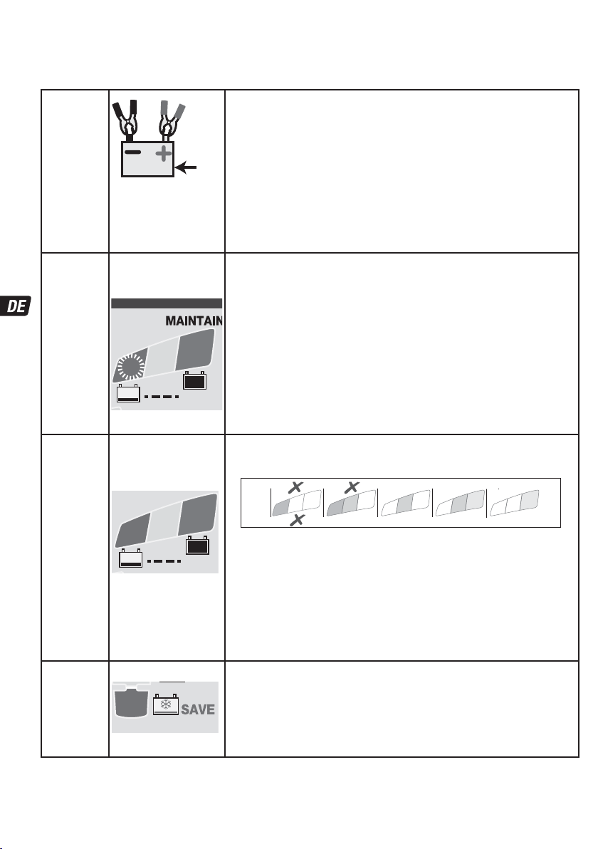
verringert die Intensität, um den Sparmodus anzuzeigen. Dies ist der Fall, wenn keine Batterie angeschlossen ist, oder die Batterie
angeschlossen ist und das Programm im Spannungserhaltungstestmodus läuft oder der Wartungsladungsmodus „Pause“ macht.
VERPOLUNGSSCHUTZ: LED #2 - leuchtet auf, wenn die Batterie falsch angeschlossen ist. Das Ladegerät ist elektronisch gegen
Beschädigung geschützt. Der Ausgang bleibt deaktiviert, bis wieder die passenden Bedingungen vorliegen.
SCHRITT 1
Starten bei
STD: Batteriespannungsprüfung - STD-Modus wird aktiviert, wenn die
Spannung der angeschlossenen Batterie mindestens 0,5 Volt beträgt.
niedriger
Spannung
(Batterie ≥
0,5V)
Bei Batterien, die beim Anschließen weniger als 2 Volt haben, wird mit SCHRITT 2 für
„Impuls-Wecken“ fortgefahren, wobei die Batterie auch auf Kurzschluss überprüft wird.
V
Bei Batterien, die 2 Volt oder mehr haben, wird direkt mit SCHRITT 3 fortgefahren.
SCHRITT 2
ImpulsWecken
SCHRITT 3
TEST vor
Laden
SCHRITT 4
Erweiterte
RETTUNG
- sulfatierte
Batterie
BLINKT
LED #8
7
8
TEST
TEST LED
#6 : GRÜN
#7: GELB
#8 : ROT
7
8
TEST
LED #3 : ROT
3
Impuls-Wecken - LED Nr. 8 (rot) blinkt: OptiMate 7 Ampmatic legt ein
Prüfsignal an, um zu ermitteln, ob die Batterie zu retten ist.
Wenn die Spannung bei über 2 Volt bleibt und kein Kurzschluss festgestellt wurde, fährt
das Programm mit SCHRITT 3 fort.
Wenn das Blinken anhält, verhindern die folgenden Bedingungen möglicherweise eine
Fortsetzung des Ladeprogramms:
1) Verbraucher im Fahrzeug bleiben mit der Batterie verbunden.
6
HINWEIS: Wenn die Batterie, die geladen wird, eine niedrige Spannung
aufweist oder sulfatiert ist, trennen Sie die Batterie von den Verbrauchern
im Fahrzeug, um ein möglichst effektives Lade- und Testergebnis zu
erzielen und fahren Sie dann mit dem Laden fort.
2) Mehrere Batteriezellen sind kurzgeschlossen. Die Batterie ist dauerhaft beschädigt
und sollte ersetzt werden.
TEST LEDs #6/7/8 zeigen den Batteriezustand vor dem Laden an. Konsultieren Sie die
Tabelle auf Seite 2, um die Anzeige der TEST-LED einem geschätzten Ladezustand in
Prozent (SOC%) anzupassen.
0
7
6
Während des Tests getroffene Entscheidungen:
SCHRITT 7 OPTIMIEREN Die Mindestladedauer wird entsprechend dem Testergebnis
eingestellt und variiert zwischen 10 Minuten bei einer Batterie mit einem Ladezustand
von 80% oder mehr und 120 Minuten bei einer Batterie mit einem Ladezustand von 40%
oder weniger. Die Umgebungstemperatur wird gemessen, um die adespannungsparameter zu bestimmen. Ladevorgang beginnt nach 10 Sekunden.
Es wird ermittelt, wie stark die Batterie entladen ist; bei einer Batterie mit 60% oder
mehr Ladung wird direkt mit SCHRITT 6 fortgefahren, während bei einer stark entladenen
Batterie zunächst die SCHRITTE 4 und 5 durchlaufen werden. Stark entladene Batterien
werden in SCHRITT 8 einem längeren Test (bis zu 12 Stunden) unterzogen.
Ladezeit: maximal 2 Stunden.
Die Ausgangsspannung erhöht sich auf maximal 22V, wobei der Strom auf 0,4A
begrenzt ist, jedoch nur, wenn keine Fahrzeugelektronik erkannt wurde, andernfalls wird
zum nächsten Schritt übergegangen. WICHTIG: Lesen Sie den Abschnitt SEHR STARK
ENTLADENE, VERNACHLÄSSIGTE BATTERIEN unten.
8
0
Wird aktiviert, wenn die Batterie als sulfatiert diagnostiziert wurde oder
nicht in der Lage ist, eine Ladung anzunehmen oder zu halten.
8
7
80 100%604020AGM
6
7
100% 806040STD
6
20
Page 21
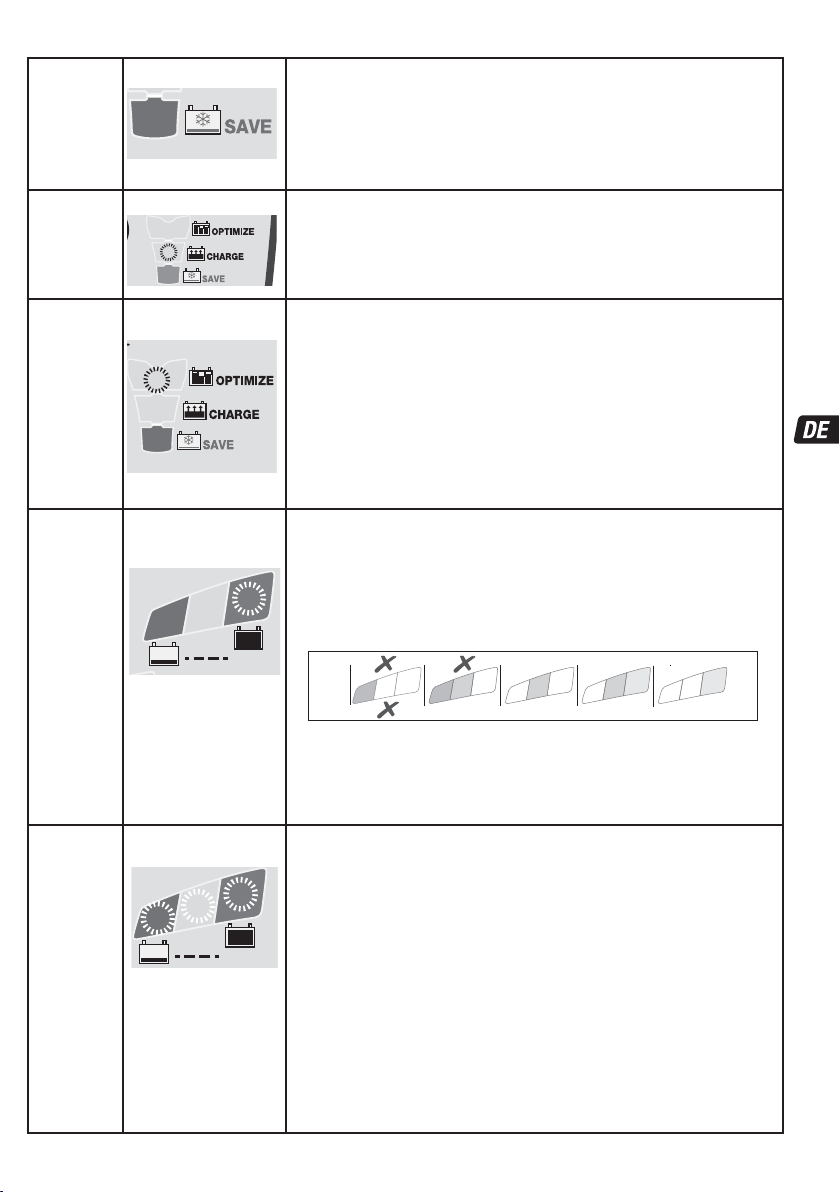
SCHRITT 5
Impuls-
RETTUNG
SCHRITT 6
LADEN
SCHRITT 7
OPTIMIEREN
SCHRITT 8
TEST nach
Laden
SCHRITT 9
OptiMate
'365'
WARTUNGS-
LADUNG
LED #3 : ROT
3
LED #4 : GELB
4
LED #5 : GELB
5
LED #6
BLINKT
6
TEST
LED #6 / 7 / 8
AN
6
7
8
TEST
Bei Batterien mit gutem
Gesundheitszustand bleibt LED
#6 (grün) an.
Ausnahme: STDNasszellenbatterien mit Deckeln
haben im vollständig geladenen
Zustand eine geringere
Spannung: LED #6 bleibt an,
zusammen mit LED #7.
Der RETTUNGS-Modus wird aktiviert, wenn der Ladezustand der Batterie weniger als
40% warm oder die Batterie als sulfatiert diagnostiziert wurde (im Test in SCHRITT 4).
LADEDAUER: Mindestens 15 Minuten, höchstens 2 Stunden.
Eine Wiederherstellungsladung wird angewandt; der Strom wird in Impulsen bereitgestellt,
um die Batterie auf das Akzeptieren einer normalen Ladung vorzubereiten. Dieser Modus ist
vor allem für die Wiederherstellung werksseitig aktivierter / von „Hochleistungs-batterien“
aus. Blei oder AGM-Batterien mit zyklischen Zellen zu empfehlen.
Der Modus LADEN wird aktiviert, wenn der Ladezustand der
Batterie 50% oder höher war (wie in SCHRITT 3 getestet),
oder sobald die Batterie in SCHRITT 5 ausreichend wiederhergestellt wurde.
Die ampmatic™ Ladestromüberwachung und -Steuerung wählt automatisch den
effizientesten Ladestrom für die angeschlossene Batterie entsprechend Ladezustand,
Batteriezustand und Speicherkapazität
Der Modus OPTIMIERUNGSLADUNG beginnt, wenn erstmalig während
Die ampmatic™ Ladestromsteuerung liefert nun Stromimpulse, um die einzelnen Zellen
innerhalb der Batterie auszugleichen und das Ladeniveau zu optimieren.
Die Ladung sollte innerhalb der in SCHRITT 3 eingestellten Mindestladedauer
abgeschlossen sein, wenn die Batterie jedoch weiter geladen werden muss, verlängert das
Programm den Modus OPTIMIERUNGSLADUNG auf maximal 2 Stunden. HINWEIS: Die
Ladedauer wird in der Regel verlängert, wenn von einem angeschlossenen Verbraucher
mehr Strom entnommen wird als erwartet oder wenn der Gesundheitszustand der Batterie
nicht optimal ist.
Aus Sicherheitsgründen ist die Gesamtladezeit für SCHRITT 4, 5 und 6 auf insgesamt
72 Stunden begrenzt.
** Wenn das Ergebnis des SCHRITT 3 ROT war (LED #8) oder ROT und GELB (LED n° 7 und
8) wird der Spannungshaltetest auf 12 Stunden verlängert, um den Gesundheitszustand der
Batterie zu überprüfen.
Das TEST-Resultat (durch LED # 6, 7, 8 angezeigt) wird in Echtzeit der gemessenen
Batteriespannung angepasst.
Der TEST wird unterbrochen, wenn LED #8 (rot) leuchtet.
Es besteht ein erhebliches Problem, wenn die Batterie im Testzeitraum keine Spannung
aufrechterhalten kann. Siehe Tabelle “FRÜHWARNUNG BEI BATTERIEPROBLEMEN” auf
Seite 2, um die Anzeige der TEST-LED einem geschätzten Ladezustand in Prozent (SOC%)
anzupassen.
Weitere Informationen finden Sie im Abschnitt “HINWEISE ZU TESTERGEBNISSEN
Einstellung Float-Spannung: 13,6V Nennspannung bei 20°C (68°F). Die Float-Spannung
wird entsprechend der Umgebungstemperatur invers reguliert, d.h., die Spannung
wird bei niedriger Temperatur erhöht und bei höherer Temperatur verringert.
Einstellung: -0,04V/Zelle/°C über oder unter 20°C (68°F).
Der Standardwartungsmodus besteht aus 30-minütigen “Erhaltungsladungszyklen”,
die mit 30-minütigen „Pausen“ abwechseln, in denen kein Ladestrom fließt. Dieser “50%
Zyklus” verhindert den Verlust von Elektrolyt in gekapselten Batterien und minimiert den
allmählichen Verlust von Wasser aus dem Elektrolyt in Batterien mit Verschlusskappen und
trägt damit erheblich zur Optimierung der Lebensdauer von unregelmäßig oder saisonal
benutzten Batterien bei.
Während der “Erhaltungsladung” wird ein kontinuierlicher IMPULS MIT GERINGER
STROMSTÄRKE AN DIE BATTERIE GESCHICKT, UM EINE SULFATABLAGERUNG ZU
UNTERBINDEN und damit Lebensdauer sowie Leistungsfähigkeit der Batterie langfristig
sicherzustellen.
Wenn der OptiMate ermittelt, dass die Batterie Ladung verloren hat, wechselt das
Programm wieder zu ‘LADEN’.
der HAUPTLADUNG die Spannung von 14,4V erreicht wurde.
TEST nach LADEN: Die Stromabgabe an die Batterie wird für
30 Minuten** unterbrochen, damit das Programm die Fähigkeit
der Batterie zum Spannungserhalt prüfen kann.
0
8
0
WARTUNGSLADUNG: LED #6 / 7 / 8 leuchten ständig, entsprechend
der bei Abschluss von SCHRITT 8 gemessenen endgültigen Spannung.
.
80 100%604020AGM
7
8
7
6
7
100% 806040STD
6
”.
21
Page 22

TIEFENTLADENE BATTERIEN: Eine tiefentladene (und möglicherweise sulfatierte) Batterie ist vor einem
Rettungsversuch auszubauen und zu überprüfen.
Der Wiederherstellungsmodus TURBO des Ladegeräts kann nicht aktiviert werden, wenn das Gerät erkennt, dass die
Batterie noch mit einem Stromkreis verbunden ist, dessen elektrischer Widerstand erheblich geringer ist als der der Batterie.
Wird die tiefentladene Batterie jedoch nicht vom Stromkreis getrennt, hat dies keine negativen Folgen für die Batterie und die
Fahrzeugelektronik. Bitte beachten: Eine für längere Zeit tiefentladene Batterie kann zu dauerhaften Schäden in einer oder
mehreren Zellen führen. Entsprechende Batterien können sich während des Ladevorgangs übermäßig stark aufheizen.
Während der ersten Stunde immer die Batterietemperatur überwachen, danach einmal pro Stunde. Auf ungewöhnliche Anzeichen
achten wie blubbernder oder auslaufender Elektrolyt, erhöhte Aktivität in einer einzelnen Zelle im Vergleich zu den anderen - oder
Zischgeräusche. Wenn die Batterie zu irgendeinem Zeitpunkt so heiß wird, dass sie nicht mehr problemlos berührt werden kann,
oder sonstige ungewöhnliche Zeichen erkennbar sind, DAS LADEGERÄT SOFORT TRENNEN.
HINWEISE ZU DEN TESTERGEBNISSEN:
1. Bei Testergebnissen, aufgrund derer LED # 6 nicht grün leuchtet (oder Nr. 6 grün und Nr. 7 gelb zusammen, falls es sich um eine
STD-Batterie mit Verschlussdeckeln handelt), die Batterie vom Verbraucher abklemmen und das OptiMate wieder anschließen.
Wenn nun ein besseres Testergebnis erzielt wird, kann das ein Hinweis darauf sein, dass nicht die Batterie das Problem ist, sondern
der elektrische Verbraucher möglicherweise defekt ist. Wenn das Ergebnis weiterhin schlecht ist, sollte die Batterie von einer
professionellen Service-Werkstatt mit professioneller Ausrüstung überprüft werden, um so eine gründlichere Untersuchung
durchzuführen.
2. Leuchtet nur die rote LED # 8 oder leuchten die gelbe LED # 7 und die rote LED # 8 zusammen (oder bei einer verschlossenen
Batterie nur die gelbe LED), liegt ein erhebliches Problem vor. Das Leuchten der roten bzw. der gelben und roten LED bedeutet, dass
die Batteriespannung nach der Aufladung nicht aufrechterhalten werden kann, oder dass ein Aufladen der Batterie nicht mehr
möglich ist. Der Grund kann ein Defekt in der Batterie selbst sein, wie z. B. ein Kurzschluss in einer Zelle oder eine vollständige
Sulfatierung. Falls die Batterie noch an einen Verbraucher angeschlossen ist, kann die rote LED # 7 auch auf einen Stromverlust
durch ein beschädigtes Kabel oder eine Beschädigung eines Schalters, eines Kontakts oder eines Zubehörteils im Stromkreis
hinweisen. Auch durch das plötzliche Einschalten einer Last bei angeschlossenem Ladegerät kann zu einem erheblichen
Spannungsverlust der Batterie führen.
3. GUTES TESTERGEBNIS, aber die Batterie liefert nicht genug Energie: a) Eine dauerhafte Beschädigung der Batterie kann zu übermäßiger
Selbstentladung führen, die innerhalb der Testdauer von 12 Stunden nicht erkannt wird. Die Batterie vom OptiMate trennen. Die Batterie
frühestens nach 48 Stunden wieder anschließen und das TEST-Ergebnis während des VORQUALIFIKATIONSTESTS beobachten.
b) Langfristige Vibrationen können Haarrisse in den Zellenverbindungen innerhalb der Batterie verursachen. Ein hoher Spannungsverlust tritt
nur bei hohem Strombedarf auf (z.B. beim Anlassen des Motors).
ERHALTUNG EINER BATTERIE ÜBER LÄNGERE ZEITRÄUME HINWEG: Das OptiMate erhält eine Batterie im gutem
Grundzustand über Monate hinweg. Prüfen Sie alle zwei Wochen die Anschlüsse zwischen Ladegerät und Batterie. Bei Batterien mit
Verschlussdeckeln für jede Zelle trennen Sie die Batterie vom Ladegerät und prüfen Sie den Flüssigkeitsstand des Elektrolyten und
füllen Sie gegebenenfalls die Zellen nach (mit destilliertem Wasser, NICHT mit Säure). Danach Ladegerät wieder anschließen. Beim
Umgang mit Batterien oder Arbeiten in ihrer Nähe sind die oben angegebenen SICHERHEITSHINWEISE unbedingt einzuhalten!
SPARMODUS, WENN DAS LADEGERÄT AN DIE NETZSPANNUNGSVERSORGUNG ANGESCHLOSSEN IST:
Der Stromrichter aktiviert den Sparmodus, wenn das Ladegerät nicht an eine Batterie angeschlossen ist, sodass ein niedriger
Stromverbrauch von weniger als 0.5 W bzw. eine Leistungsaufnahme von 0,012 kWh pro Tag vorliegt. Wenn eine Batterie an das
Ladegerät angeschlossen wird, wird die Leistungsaufnahme vom Verbrauch der Batterie und des angeschlossenen Fahrzeugs bzw.
der elektronischen Verbraucher bestimmt. Wenn die Batterie aufgeladen ist und sich das Ladegerät im langfristigen
Wartungsladungsmodus befindet (um die vollständige Ladung aufrechtzuerhalten), beträgt die gesamte Leistungsaufnahme
voraussichtlich höchstens 0,024 kWh pro Tag.
BEGRENZTE GARANTIE
TecMate (International) N.V., Sint-Truidensesteenweg 252, B-3300 Tienen, Belgien, gewährt dem ursprünglichen Käufer beim
Kauf dieses Produktes diese begrenzte Garantie. Diese begrenzte Garantie ist nicht übertragbar. TecMate (International)
übernimmt für drei Jahre ab Verkaufsdatum die Garantie für dieses Batterieladegerät hinsichtlich Material- oder
Verarbeitungsfehlern. Sollten solche Fehler auftreten, wird das Gerät nach Ermeßen des Herstellers repariert oder ersetzt. Es ist
Sache des Käufers, das Gerät zusammen mit dem Kaufnachweis (siehe "BEACHTUNG) "an den Hersteller oder seinen
ermächtigten Vertreter einzuschicken, wobei der Käufer die Transport- oder Portokosten trägt. Diese begrenzte Garantie ist
nichtig, wenn das Produkt mißbräuchlich verwendet, unsachgemäß behandelt oder nicht vom Werk oder einem ermächtigten
Vertreter repariert wurde.
EINWIRKUNG VON FLÜSSIGKEITEN: Die Garantie gilt nicht für Schäden am Gerät bzw. den elektronischen Komponenten,
Steckverbindern oder Steckern, die durch eindringende korrosive Flüssigkeiten verursacht wurden.
Der Hersteller gewährt außer dieser begrenzten Garantie keinerlei Garantie und schließt ausdrücklich jede implizite
Gewährleistung, einschließlich jeglicher Garantie gegen Folgeschäden aus.
DIES IST DIE EINZIGE AUSDRÜCKLICHE BEGRENZTE GARANTIE, UND DER HERSTELLER ÜBERNIMMT KEINERLEI
VERPFLICHTUNG GEGENÜBER DEM PRODUKT. IHRE GESETZLICHEN RECHTE SIND NICHT BETROFFEN.
BEACHTUNG: Siehe www.tecmate.com/warranty oder kontaktieren Sie warranty@tecmate.com
OptiMate 7 und die Namen anderer Produkte wie BatteryMate, TestMate und TestMate mini, die in diesen Anweisungen
erwähnt werden,sind geschützte Warenzeichen von TecMate International NV.
Mehr Informationen über TecMate Produkten können bei www.tecmate.com gefunden werden.
22
Page 23
LADER MET AUTOMATISCHE DIAGNOSE VOOR 12 V LOODZUURACCU’S.
NIET GEBRUIKEN VOOR NiCd-, NiMH-, Li-ion- OF NIET-OPLAADBARE ACCU’S.
VEILIGHEIDSWAARSCHUWING EN OPMERKINGEN: ALS U DE 'BELANGRIJKE
VEILIGHEIDSINSTRUCTIES' OP DE VORIGE PAGINA'S NOG NIET HEBT GELEZEN, LEES ZE DAN EERST VOOR U
DE LADER GEBRUIKT.
Dit apparaat is niet bedoeld voor gebruik door personen (met inbegrip van kinderen) met beperkte
lichamelijke, zintuiglijke of mentale vermogens of gebrek aan ervaring en kennis, tenzij ze onder toezicht
staan of instructie hebben gekregen inzake het gebruik van het apparaat van een persoon die
verantwoordelijk is voor hun veiligheid. Kinderen moeten onder toezicht staan om er zeker van te zijn dat
ze niet met het apparaat spelen.
VEILIGHEIDSWAARSCHUWING EN OPMERKINGEN: Accu's stoten EXPLOSIEVE GASSEN uit - voorkom het ontstaan van
vlammen of vonken in de buurt van de accu. De stekker van de lader mag niet in het stopcontact zitten, wanneer gelijkstroom-/
accuverbindingen gemaakt of verbroken worden. Accuzuur is in hoge mate corrosief. Draag beschermende kleding en
oogbescherming en vermijd contact. Bij onbedoeld contact onmiddellijk met water en zeep wassen. Controleer of de
accuaansluitingen vastzitten; als dat niet het geval is, moet u de accu door een vakman laten nakijken. Als de accuaansluitingen
aangetast zijn, reinigt u ze met een koperdraadborstel; als ze vettig of vuil zijn, reinigt u ze met een doek die bevochtigd is met
reinigingsmiddel. Gebruik de lader alleen als de ingangs- en uitgangsdraden en aansluitingen onbeschadigd en in goede staat zijn.
Met het oog op uw veiligheid moet u een beschadigde ingangskabel meteen laten vervangen door de fabrikant of een erkende
reparateur. Bescherm de lader tegen zuur en zuurdampen, en tegen damp en vochtigheid, zowel tijdens het gebruik als bij de
opslag. Schade als gevolg van corrosie, oxidatie of interne elektrische kortsluiting valt niet onder de garantie. Zorg tijdens het
opladen voor voldoende afstand tussen de lader en de accu, om contact met of blootstelling aan zuur of zure dampen te voorkomen.
Als u de lader horizontaal gebruikt, plaatst u hem op een harde, vlakke ondergrond maar NIET op plastic, textiel of leer. Onderaan in
de voetplaat zitten gaten om de lader te bevestigen op een geschikt verticaal oppervlak dat in goede staat verkeert.
BLOOTSTELLING AAN VLOEISTOFFEN:
bovenaf op de behuizing, of lichte regenval te weerstaan. Het wordt afgeraden de lader lang aan regen bloot te stellen, met het oog
op een langere levensduur. Defecten aan de lader door oxidatie die het gevolg is van eventuele insijpeling van vloeistoffen in de
elektrische onderdelen, aansluitingen of stekkers, vallen niet onder de garantie.
DE LADER AANSLUITEN OP DE ACCU
1. De stekker van de lader mag niet in het stopcontact zitten, wanneer gelijkstroom-/accuverbindingen gemaakt of verbroken
worden.
2. Indien u een accu in een voertuig met de accuklemmen gaat opladen, dient u, voordat u de lader aansluit, te controleren of de
accuklemmen veilig en op voldoende afstand van de omringende bedrading, metalen buizen en het chassis geplaatst kunnen
worden. Sluit de lader aan in deze volgorde: sluit eerst de pool van de accu aan die niet verbonden is met het chassis (meestal
positief), sluit daarna de andere accuklem aan (meestal negatief) op het chassis op ruime afstand van de accu en de
brandstofleiding. Ontkoppel de lader in omgekeerde volgorde.
3. Plaats de accu in een goed geventileerde ruimte wanneer u een accu met accuklemmen buiten het voertuig gaat opladen. De
lader aansluiten op de accu: RODE klem op de POSITIEVE (POS, P of +) pool en ZWARTE klem op de NEGATIEVE (NEG, N of –)
pool. Zorg dat de klemmen stevig en veilig zijn bevestigd. Een goed contact is belangrijk.
4. Als de accu zwaar ontladen (en mogelijk gesulfateerd) is, dient de accu uit het voertuig verwijderd en gecontroleerd te
worden voordat een poging wordt ondernomen om de accu te herstellen. Controleer de accu visueel op mechanische
defecten zoals bol staan, gescheurde behuizing of tekenen van elektrolytlekkage. Als de accu vuldoppen heeft en de platen in
de cellen vanaf de buitenzijde zichtbaar zijn, kunt u zorgvuldig proberen vast te stellen of bepaalde cellen afwijken van andere
(bijvoorbeeld wit materiaal tussen de platen, platen die elkaar raken). Probeer de accu niet op te laden wanneer mechanische
defecten zichtbaar zijn, maar laat de accu door een vakman nakijken.
5. Voor een nieuwe accu: Lees de veiligheidsinstructies en de gebruiksaanwijzing van de fabrikant zorgvuldig door voordat u de
lader aansluit op een nieuwe accu. Volg, indien van toepassing, de instructies betreffende het vullen van zuur zorgvuldig en
nauwkeurig op.
HET LADEN STARTEN
OPLAADTIJD : De laadtijd voor een lege, maar onbeschadigde accu bedraagt iets minder dan 25% van de capaciteit in Ah. Zo zou
het voor een accu van 100 Ah maximaal 12 uur mogen duren om tot de zelfontladingscontrole te komen.
Voor diep ontladen accu's is de oplaadtijd aanzienlijk langer.
: De laadspanning en druppellaadspanning wordt omgekeerd evenredig met de omgevingstemperatuur geregeld. Dat betekent
dat de spanning wordt verhoogd bij lagere temperaturen en verlaagd bij hogere temperaturen. Aanpassing: -0,004 V / cel / °C boven
of onder 20 °C.
VOEDING AAN: LED #1 - Bevestigt de AC-voeding naar de lader.
HOGE en LAGE intensiteitsweergave: De 'VOEDING AAN' LED #1 zal fel branden wanneer stroom wordt geleverd aan de accu. De
'VOEDING AAN' LED #1 brandt minder fel in de energiezuinige 'ECO'-modus. Dit gebeurt als geen accu aangesloten is of als er een
Deze lader is ontworpen om per ongeluk gemorste of spatten van vloeistoffen van
23
VEILIGHEID
Page 24
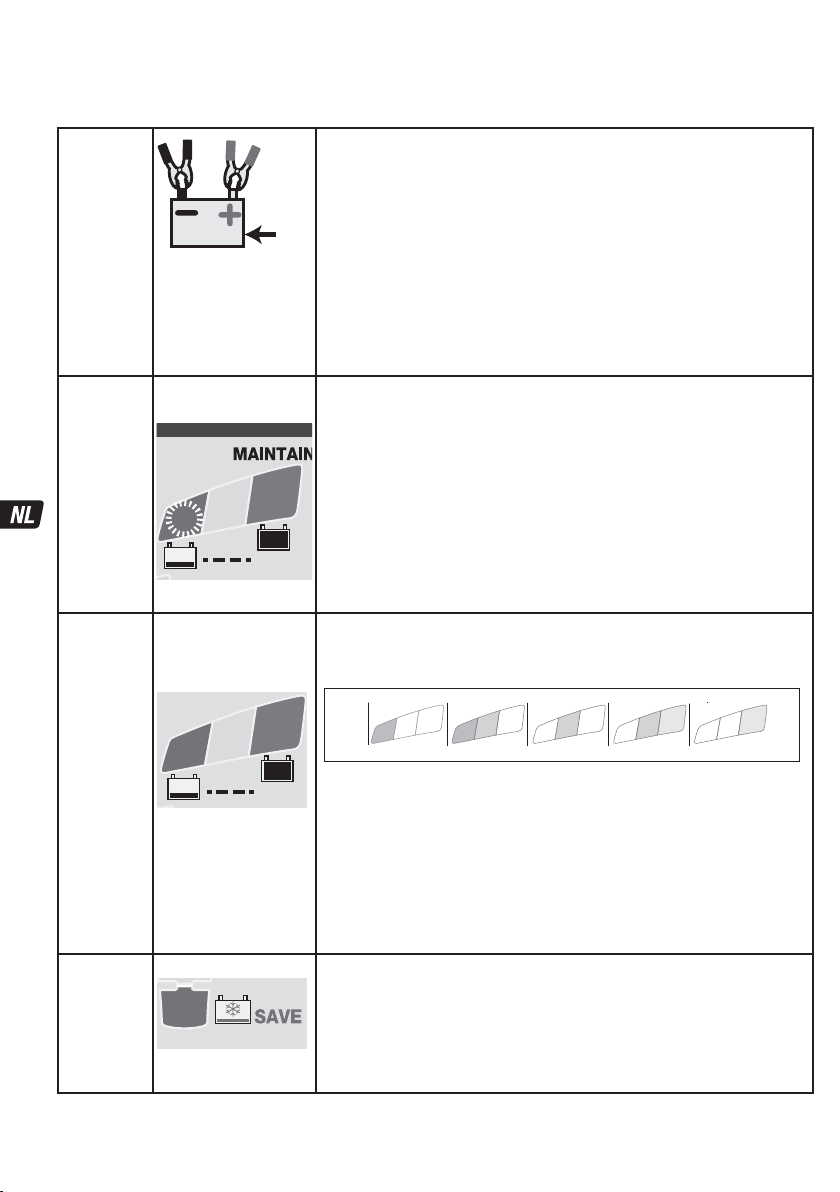
accu aangesloten is en het programma zich in de ’test op behoud van spanning’ of de 'rustperiodes' van de onderhoudslaadmodus
bevindt.
BESCHERMING TEGEN OMGEKEERDE POLARITEIT: LED #2 - brandt wanneer de accu verkeerd is aangesloten. De lader is elektronisch
beveiligd, zodat er niets wordt beschadigd. De uitgang zal uitgeschakeld blijven tot de aansluitingen correct zijn.
STAP 1
Start met
lage
spanning
(accu ≥ 0,5
V)
STAP 2
Pulsactivering
STAP 3
TEST voor
het laden
STAP 4
Geavanceerde
SAVE
–
gesulfateerde
accu
LED #8 KNIPPERT
6
7
8
TEST
TEST LED
#6: GROEN
#7: GEEL
#8: ROOD
6
7
8
TEST
LED #3 : ROOD
3
STD: controle van accuspanning - STD-modus wordt geactiveerd wanneer
de spanning van de aangesloten accu minstens 0,5 V is.
Accu's met een meetwaarde van minder dan 2 V bij de aansluiting
gaan naar STAP 2 – pulsactivering – waarbij de accu wordt getest op kortsluiting.
V
Accu's met een meetwaarde van 2 V of meer gaan rechtstreeks naar STAP 3.
Pulsactivering – LED nr. 8 (rood) knippert: de OptiMate 7 Ampmatic
verstuurt een testsignaal om te bepalen of de accu kan worden hersteld.
Indien de spanning boven 2 V blijft en er geen kortsluiting is vastgesteld, begint het
programma bij STAP 3.
Indien het lampje blijft knipperen, kunnen de volgende situaties voorkomen dat de accu
wordt opgeladen:
1) Het voertuigcircuit is aangesloten op de accu.
OPMERKING: Indien de op te laden accu een lage spanning heeft of in
gesulfateerde staat verkeert, koppelt u de accu voor de beste laad- en
testresultaten los van het voertuigcircuit en laadt u de accu vervolgens op.
2) Meerdere accucellen zijn kortgesloten. De accu is permanent beschadigd en moet
worden vervangen.
De TESTLED's #6/7/8 geven de accustatus voorafgaand aan het laden weer. Raadpleeg
de onderstaande tabel of de tabel op pagina 2 voor een vergelijking van de gegevens van
de testleds met de geschatte laadstatus (SOC%).
0
8
0
Tijdens de test gemaakte beslissingen:
STAP 7 OPTIMALISEREN: de minimale laadtijd wordt ingesteld in functie van het
testresultaat en varieert tussen 10 minuten voor een accu die 80% of meer geladen is tot
120 minuten voor een accu die 40% of minder geladen is.
Voor het instellen van de laadparameters wordt de omgevingstemperatuur gemeten.
Het laden start na 10 seconden.
De mate van ontlading wordt bepaald: een accu die voor 60% of meer geladen is, gaat
rechtstreeks door naar STAP 6, terwijl een sterk ontlade accu STAP 4 en 5 doorloopt.
Sterk ontlade accu's ondergaan een langere test (tot 12 uur) tijdens STAP 8.
de laadstroom niet kan accepteren of vasthouden.
Laadtijd: maximaal 2 uur.
Uitgangsspanning neemt toe tot maximaal 22 V met een stroom die wordt beperkt tot 0,4
A op voorwaarde dat er geen voertuigelektronica is gedetecteerd; zo niet wordt er naar
de volgende stap overgegaan. BELANGRIJK: Lees het deel ZEER LEGE, VERWAARLOOSDE
ACCU'S hieronder.
7
8
Schakelt in wanneer de accu gesulfateerd is of
7
80 100%604020AGM
6
7
100% 806040STD
6
24
Page 25
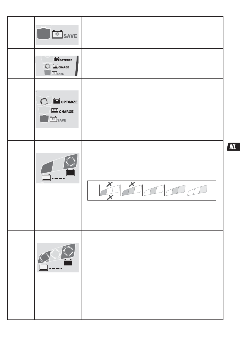
STAP 5
PULSE SAVE
STAP 6
LADEN
LED #3 : ROOD
3
LED #4 : GEEL
4
Schakelt in wanneer de laadstatus van de accu 40% of minder bedraagt
OF wanneer de accu tijdens TURBO SAVE voldoende is hersteld.
Laadtijd: minimaal 15 minuten, maximaal 2 uur. Er wordt een herstellading aangevoerd.
Er wordt een stroom geleverd in pulsen om de accu voor te bereiden op de ontvangst van
een normale laadstroom. Deze modus is met name effectief voor het herstellen van in de
fabriek geactiveerde/‘hoogwaardige’ AGM lood- of cyclische accu’s.
De LAADmodus wordt geactiveerd als de accu meer dan 50% of meer ontladen is
(zoals getest bij STAP 3) of zodra de accu voldoende hersteld is tijdens STAP 5.
Het programma ampmatic™ voor de monitoring en controle van de laadstroom
bepaalt automatisch de efficiëntste laadstroom voor de aangesloten accu op basis van de
laadtoestand, de conditie van de accu en het opslagvermogen.
STAP 7
OPTIMALI-
SEREN
STAP 8
TEST na
laden
STAP 9
OptiMate
'365'
onderhoud
LED #5 : GEEL
Het stroomcontroleprogramma ampmatic™ levert nu stroompulsen om de
individuele cellen in de accu op gelijke spanning te brengen en optimaliseert het
5
laadniveau.
Het laden zou voltooid moeten zijn binnen de minimale laadtijd die is ingesteld bij STAP
3. Wanneer de accu nog verder moet worden geladen, verlengt het programma de
OPTIMALISEERmodus tot maximaal 2 uur.
Nota: de laadtijd wordt doorgaans verlengd indien het systeem een hoger dan verwacht
stroomgebruik van aangesloten circuits vaststelt of de conditie van de accu verre van
optimaal is.
Om veiligheidsredenen is de totale laadtijd beperkt tot 72 uur voor STAPPEN 4, 5 en 6.
LED #6 KNIPPERT
** ALS het resultaat in STAP 3 ROOD was (led #8) of ROOD en GEEL (led #7 en 8), wat
6
aangeeft dat de accu vóór het aansluiten sterk ontladen was, wordt de
spanningsbehoudtest verlengd tot 12 uur om de accuconditie te bevestigen. Het
TEST
testresultaat (aangegeven met leds # 6, 7, 8) wordt realtime aangepast aan de gemeten
accuspanning.
De test wordt onderbroken wanneer led #8 (rood) brandt. Er is sprake van een
ernstig probleem als de accu niet in staat is om voldoende lading vast te houden
gedurende de testperiode. Raadpleeg de tabel ‘VROEGE TEKENEN VAN
ACCUPROBLEMEN’ op pagina 2 voor een vergelijking van de gegevens van de testleds
met de geschatte laadstatus (SOC%).
U vindt meer informatie in het hoofdstuk ‘OPMERKINGEN OVER DE TESTRESULTATEN’.
LED #6 / 7 / 8
AAN
7
8
TEST
Voor accu’s in een gezonde
conditie blijft LED #6 (groen)
branden.
Uitzondering: STD nattecel-accu’s
met vuldoppen hebben een lager
volledig geladen voltage: LED #6
blijft samen met led #7 branden.
Instelling druppellaadspanning: 13,6 V nominaal bij 20 °C (68 °F). De
druppellaadspanning wordt omgekeerd evenredig met de omgevingstemperatuur
6
geregeld. Dat betekent dat de spanning wordt verhoogd bij lagere temperaturen en
verlaagd bij hogere temperaturen. Aanpassing: -0,04 V / cel / °C boven of onder 20 °C
(68 °F).
De standaard onderhoudslaadcyclus bestaat uit druppellaadperiodes van 30 minuten
gevolgd door telkens een rustperiode van 30 minuten. Tijdens de rustperiodes is er geen
laadstroom. Deze ‘50% bedrijfscyclus’ voorkomt verlies van elektrolyten in verzegelde
accu’s en minimaliseert geleidelijk verlies van water uit de elektrolyt in accu’s met
vuldoppen, waardoor een significante bijdrage wordt geleverd aan het optimaliseren van
de levenscyclus van onregelmatig of seizoensgebonden gebruikte accu’s.
Tijdens de druppellaadperiodes wordt een continu LAGE STROOMPULS GELEVERD OM
SULFATERING TE VOORKOMEN, het accuvermogen te vergroten en de levensduur te
verlengen.
Als de OptiMate vaststelt dat de accu spanning heeft verloren, keert het
programma terug naar STAP LADEN.
De OPTIMALISEERmodus start wanneer de spanning
tijdens de LAADmodus voor de eerste keer 14,4 V bedraagt.
TEST NA LADEN: De levering van stroom aan de accu wordt gedurende
30 minuten** onderbroken, zodat het programma kan bepalen
of de accu in staat is om de lading vast te houden.
0
8
0
ONDERHOUDSCYCLUS: Leds #6/7/8 branden constant
overeenkomstig de laadstatus die tijdens STAP 8 gemeten is.
7
8
7
80 100%604020AGM
6
7
100% 806040STD
6
25
Page 26

ZEER PLATTE, VERWAARLOOSDE ACCU’S: Als de accu zwaar ontladen (en mogelijk gesulfateerd) is, dient de accu uit
het voertuig verwijderd en gecontroleerd te worden voordat een poging wordt ondernomen om de accu te herstellen.
De TURBO-herstelmodus van de lader kan niet worden ingeschakeld wanneer de lader detecteert dat de accu nog steeds is
aangesloten op het bedradingscircuit. De elektrische weerstand van een aangesloten accu is namelijk duidelijk lager dan die van
de accu alleen. Wanneer een diep ontladen accu voorafgaand aan een herstelpoging niet is verwijderd, zal dit echter geen schade
toebrengen aan de elektronica van het voertuig of de accu. Lees aandachtig het volgende: een accu die voor lange tijd diep
ontladen is geweest, kan blijvende schade ontwikkelen in een of meer cellen. Dit soort accu's kan tijdens het opladen met sterke
stroom uitzonderlijk warm worden.
Controleer de temperatuur van de accu tijdens het eerste uur, daarna om het uur. Controleer op ongebruikelijke tekenen, zoals
bubbelend of lekkend elektrolyt, sterkere activiteit in één cel in vergelijking met andere cellen, of sisgeluiden. Wanneer de accu op
een bepaald moment zo warm wordt dat u hem niet meer kunt aanraken of er ongewone tekenen zijn, KOPPELT U DE LADER
METEEN LOS.
OPMERKINGEN OVER DE TESTRESULTATEN:
1. Voor een ander testresultaat dan groen #6 (of groen #6 en geel #7 samen als de accu van het STD type met vuldoppen is),
koppelt u de accu los van het elektrische systeem dat hij ondersteunt en sluit de OptiMate opnieuw aan. Indien het testresultaat nu
beter is, is het stroomverlies gedeeltelijk te wijten aan een elektrisch probleem in het elektrische systeem en niet in de accu zelf. Als
het resultaat nog niet beter is, wordt aangeraden de accu naar een professionele servicewerkplaats met professioneel materiaal te
brengen voor een grondinger onderzoek.
2. Wanneer alleen LED #8 (rood) brandt of wanneer LED 7# (geel) en LED #8 (rood) beide branden (of gele LED alleen bij een
verzegelde accu), is er sprake van een ernstig probleem. De rode / gele+rode LEDs betekent dat de accuspanning na het laden niet
wordt vastgehouden of dat ondanks verschillende recuperatiepogingen de accu niet kon worden gerecupereerd. De oorzaak kan te
vinden zijn in de accu zelf, bijvoorbeeld een kortgesloten cel of volledige sulfatie of corrosie. Wanneer de accu nog op het elektrische
systeem dat hij ondersteunt is aangesloten kan de rode LED 8# ook een stroomverlies betekenen dat te wijten is aan versleten
bedrading of een defecte schakelaar of contact, of aan stroomverbruikende accessoires op hetzelfde circuit. Een plotse belasting die
wordt ingeschakeld terwijl de lader is aangesloten, kan ook leiden tot een aanzienlijk spanningsverlies van de accu.
3. GOED TESTRESULTAAT, maar de accu kan niet voldoende vermogen leveren: a) blijvende schade in de accu kan een overmatige
zelfontlading veroorzaken die niet kan worden opgespoord tijdens de testperiode van 12 uur. Koppel de accu los van de OptiMate. Wacht
minstens 48 uur voordat u de lader opnieuw aansluit, en houd de TESTresultaten tijdens de PREKWALIFICATIETEST in de gaten. b) Langdurig
trillen kan tot haarscheurtjes in intercelconnectoren in de accu leiden. Een groot spanningsverlies doet zich alleen bij een hoge stroombehoefte
(bv. bij het starten van de motor) voor.
DE ACCU ONDERHOUDEN VOOR LANGERE PERIODEN: De OptiMate onderhoudt een accu waarvan de basistoestand goed
is gedurende maanden aan een stuk. Controleer ten minste eenmaal per twee weken of de aansluitingen tussen de lader en accu
betrouwbaar zijn, en, in geval van accu's met vuldoppen op iedere cel, ontkoppel de accu van de lader, controleer het elektrolytpeil
en vul de cellen zo nodig bij (met gedestilleerd water, NIET met zuur); sluit de accu vervolgens weer op de lader aan. Neem
bovenstaande VEILIGHEIDSWAARSCHUWINGEN altijd in acht wanneer u de accu vastpakt of in de buurt van een accu bent.
ECO-STROOMBESPARINGSMODUS WANNEER DE LADER OP HET ELEKTRICITEITSNET IS AANGESLOTEN:
De vermogensomzetter gaat in ECO-modus wanneer de lader niet op een accu is aangesloten. Dit resulteert in een stroomopname
van minder dan 0,5 W, wat overeenkomt met een stroomverbruik van 0,012 kWh per dag. Als een accu op de lader is aangesloten is
het stroomverbruik afhankelijk van de stroombehoefte van de accu en het aangesloten voertuig / de elektronische circuits. Wanneer
de accu opgeladen is en het laadprogramma in de langetermijnonderhoudslaadmodus staat (om de accu 100% vol te houden) wordt
het totale stroomverbruik geraamd op 0,024 kWh per dag of minder.
BEPERKTE GARANTIE
TecMate (International) SA, Sint-Truidensesteenweg 252, B-3300 Tienen, België, staat deze beperkte garantie toe aan elke
eerste koper van dit toestel. Deze beperkte garantie gaat in op de dag van aankoop en is niet overdraagbaar. De drie jaar
geldige garantie aangeboden door TecMate (International) dekt alle erkende gebreken en arbeidskosten. Indien de lader defect
blijkt te zijn tengevolge van een constructiefout, zal de klant het toestel altijd vooraf en op eigen kosten terugsturen naar de
fabrikant of naar de nationale officiële verdeler, samen met een kopij van de aankoopfactuur (zie "NOTITIE"). In zulke gevallen,
zal de eenheid ter keuze van de fabrikant worden hersteld of worden vervangen.Onkosten tengevolge van een ongeval,
slordigheid, kwaadwilligheid, misbruik, niet conform gebruik volgens de aanwijzingen van de fabrikant, of herstellingen gedaan
door door TecMate niet-erkende verdelers, zijn niet gedekt door de garantie.
DE BEPERKTE GARANTIE SLUIT UITDRUKKELIJK ALLE VERDERE VERANTWOORDELIJKHEID UIT MET BETREKKING TOT
EVENTUELE SCHADEVERGOEDINGEN VAN WELKE AARD DAN OOK. UW STATUTAIRE RECHTEN WORDEN NIET BEÏNVLOED.
NOTITIE: Zie www.tecmate.com/warranty of contacteer warranty@tecmate.com.
OptiMate 7 en de namen van andere producten zoals BatteryMate, TestMate en TestMate mini, die in deze instructies worden
vermeld, zijn gedeponeerd handelsmerken van TecMate International NV.
Meer informatie overTecMate productenkanop www.tecmate.com worden gevonden.
26
Page 27
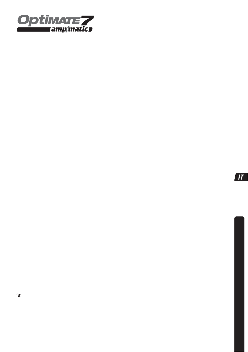
CARICABATTERIE AUTOMATICO CON DIAGNOSTICO PER BATTERIE PIOMBO-ACIDO 12 V
NON UTILIZZARE PER BATTERIE NiCd, NiMH, IONI DI LITIO O PER BATTERIE NON
RICARICABILI.
AVVERTENZA DI SICUREZZA E NOTE: SE NON LO SI È ANCORA FATTO, LEGGERE LE PAGINE
PRECEDENTI CONTRASSEGNATE COME "ISTRUZIONI DI SICUREZZA IMPORTANTI" PRIMA DI AZIONARE IL
CARICABATTERIE.
L'utilizzo di quest’apparecchio non è consentito alle persone (bambini inclusi) con ridotte capacità fisiche, sensoriali o
mentali, o con mancanza di esperienza e conoscenza, salvo sotto supervisione o a meno che non abbiano avuto istruzioni
riguardanti l'uso del apparecchio da parte di persone responsabili della loro sicurezza. I bambini devono essere sorvegliati
affinché non giochino con il apparecchio.
AVVERTENZA DI SICUREZZA E NOTE: Le batterie emettono GAS ESPLOSIVI – prevenire fiamme o scintille in prossimità
di batterie. Scollegare l'alimentazione CA prima di effettuare o interrompere connessioni con la batteria/CC. L'acido della batteria è
altamente corrosivo. Indossare abbigliamento protettivo ed occhiali, ed evitare il contatto. In caso di contatto accidentale, lavare
immediatamente con acqua e sapone. Controllare che i poli della batteria non siano allentati. Se così fosse, rivolgersi ad un esperto
per sistemarli. Se i poli della batteria sono corrosi, pulirli con una spazzola di rame; se sono unti oppure sporchi, pulirli con uno
straccio inumidito con detergente. Utilizzare il caricabatterie soltanto se i poli e i connettori di ingresso e di uscita sono in buona
condizione e non danneggiati. Se il cavo di ingresso è danneggiato, è essenziale farlo sostituire immediatamente dal produttore, dal
riparatore autorizzato o da un'officina qualificata, per evitare pericoli. Proteggere il caricabatterie da acido, fumi acidi e umidità sia
durante l'uso che nell'immagazzinamento. I danni derivanti da corrosione, ossidazione o cortocircuiti elettrici interni non sono
coperti dalla garanzia. Distanziare il caricabatterie dalla batteria durante la carica per evitare la contaminazione o l'esposizione
all'acido o ai vapori acidi. Se lo si utilizza nell'orientamento orizzontale, collocare il caricabatterie su una superficie dura e piana, ma
NON su plastica, tessuto o cuoio. Utilizzare i fori di fissaggio forniti nella base dell'involucro per collegare il caricabatterie a
qualunque superficie verticale pratica e comoda.
ESPOSIZIONE AI LIQUIDI: Questo caricabatterie è destinato a sopportare l'esposizione ai liquidi rovesciati o spruzzati
accidentalmente sull'involucro dall'alto, o a una leggera pioggia. L'esposizione prolungata alla pioggia è sconsigliata e si otterrà una
maggiore durata riducendo al minimo tale esposizione. Un guasto del caricabatterie dovuto all'ossidazione derivante dalla
penetrazione eventuale di liquido nei componenti elettronici, nei connettori o nelle spine non è coperto da garanzia.
CONNESSIONE DEL CARICABATTERIE ALLA BATTERIA
1. Scollegare l'alimentazione CA prima di effettuare o di eliminare delle connessioni alla batteria/CC.
2. Se si carica la batteria del veicolo con i morsetti della batteria, prima di effettuare le connessioni verificare che i morsetti della
batteria possano essere posizionati in modo sicuro e protetto, distanti da cavi e tubi metallici circostanti o dal telaio. Effettuare
le connessioni procedendo come segue: per prima cosa, collegare il terminale della batteria non collegato al telaio (solitamente
positivo), quindi collegare l'altro morsetto della batteria (solitamente negativo) al telaio, mantenendo le distanze dalla batteria e
dalla linea del combustibile. Scollegare sempre nella sequenza contraria.
3. Quando si carica una batteria smontata dal veicolo utilizzando i morsetti della batteria, posizionare quest'ultima in una zona
ben ventilata. Collegare il caricabatterie alla batteria: morsetto ROSSO a terminale POSITIVO (POS, P o +) e morsetto NERO a
terminale NEGATIVO (NEG, N o –).Verificare che le connessioni siano salde e sicure. Un buon contatto è fondamentale.
4. Se la batteria è molto scarica (e probabilmente solfatata), rimuoverla dal veicolo e ispezionarla prima di collegare il
caricabatterie per effettuare un tentativo di recupero. Effettuare un'ispezione visiva della batteria per rilevare la presenza di
eventuali difetti meccanici, quali una scatola curvata o incrinata, oppure segni di perdite di elettroliti. Se la batteria presenta
tappi per riempimento e le placche nelle celle sono visibili dall'esterno, esaminare attentamente la batteria per cercare di
stabilire se alcune celle hanno un aspetto diverso dalle altre (ad esempio, se presentano del materiale bianco tra le placche o
se le placche sono in contatto tra loro). Qualora vengano rilevati difetti meccanici, non cercare di ricaricare la batteria, ma
sottoporla a una verifica da parte di esperti.
5. Se la batteria è nuova, prima di procedere alla connessione del caricabatterie, leggere attentamente le istruzioni di sicurezza
e di funzionamento del produttore della batteria. Ove necessario, attenersi scrupolosamente alle istruzioni di riempimento di
acido.
ESECUZIONE DELLA CARICA
TEMPO DI CARICA : Il tempo di carica di una batteria da 100 Ah non dovrebbero essere necessarie più di 12 ore per passare al
modo di prova automatico .Per le batterie molto scariche potrebbe essere necessario molto più tempo.
: La tensione di carica e la tensione di mantenimento è regolata inversamente rispetto alla temperatura ambiente, ovvero viene
aumentata a temperature minori e diminuita a temperature maggiori. Regolazione: -0,04 V/cella/°C sopra o sotto 20 °C (68 °F).
ACCENSIONE: LED #1 - Conferma l'alimentazione CA al caricabatterie.
Indicazione di ALTA e BASSA intensità: Il LED #1 DI ACCENSIONE è alla normale intensità quando la corrente arriva alla batteria.
L'intensità del LED #1 DI ACCENSIONE si affievolisce fino a un livello minimo per indicare il modo "ECO" a bassa potenza. Ciò
avviene quando non vi è alcuna batteria collegata, o quando una batteria è collegata e il programma si trova nelil modo di
mantenimento o nei cicli di "riposo" di prova di ritenzione della carica.
PROTEZIONE CONTRA L’INVERSIONE DI POLARITÀ: LED #2 - Si accende quando i collegamenti della batteria non sono
effettuati correttamente. Il caricabatterie è dotato di protezione elettronica, pertanto non può subire danni. L'uscita resta
disabilitata fino alla correzione dell'errore di collegamento.
. stati
27
SICUREZZA
Page 28

FASE 1
Geavanceerde
SAVE
–
gesulfateerde
accu
STD: controllo della tensione della batteria - la modalità STD si attiva se la
tensione della batteria collegata è almeno di 0,5 Volt.
Le batterie aventi una tensione inferiore a 2 Volt al momento della connessione
passeranno alla
V
FASE 2 “Risveglio a impulsi”, che prevede un test di cortocircuito della batteria.
Le batterie con tensione pari o superiore a 2 Volt passeranno direttamente alla FASE 3.
FASE 2
Risveglio a
impulsi
FASE 3
TEST prima
della carica
FASE 4
RICUPERO
avanzato
- batteria
solfatata
LED #8 LAMPEGGIA
6
7
8
TEST
LED DI TEST
6: VERDE
7: GIALLO
8: ROSSO
6
7
8
TEST
LED #3 : ROSSO
3
Risveglio a impulsi - Il LED #8 (rosso) lampeggia: OptiMate 7 Ampmatic sta
inviando un segnale di prova per verificare se la batteria è recuperabile.
Se la tensione si mantiene sopra i 2 Volt e non è stato rilevato nessun cortocircuito, il
programma avvierà la FASE 3.
Se il LED continua a lampeggiare, è possibile che le seguenti condizioni impediscano
l'avanzamento del programma di carica:
1) I circuiti del veicolo sono rimasti connessi alla batteria.
NOTA: se la batteria in carica è a bassa tensione o solfatata per ottenere
una carica e risultati dei test ottimali, scollegare la batteria dai circuiti del
veicolo prima di avviare il programma di carica.
2) La batteria ha diverse celle in cortocircuito. La batteria presenta danni permanenti
e deve essere sostituita.
I LED DI TEST 6/7/8 indicano lo stato della batteria prima della carica. Consultare la
tabella riportata di seguito o a pagina 2 per abbinare l'indicazione del LED DI TEST a uno
stato di percentuale di carica (SOC%) stimato.
0
8
0
Decisioni prese durante il tes:
FASE 7, OTTIMIZZAZIONE: il tempo di carica minimo è impostato in base al risultato del
test, e varia tra 10 minuti per una batteria con l'80% o più di carica e 120 minuti per una
batteria al 40% o meno. La temperatura ambiente viene misurata al fine di determinare i
parametri della tensione di carica. La ricarica inizia dopo 10 secondi.
Viene determinata la criticità dello stato di scaricamento: una batteria con un livello di
carica pari o superiore al 60% passa direttamente alla FASE 6, mentre una batteria con
un livello di carica estremamente basso passa alle FASI 4 e 5. Le batterie molto scariche
verranno sottoposte a un test più lungo (fino a 12 ore) durante la FASE 8.
Si attiva se la diagnostica ha rilevato una batteria solfatata,
Tempo di carica: 2 ore massimo.
La tensione di uscita aumenta a un massimo di 22 V con corrente limitata a 0,4 A, ma
solo se non è stata rilevata l'elettronica del veicolo; in caso contrario passa alla fase
successiva. IMPORTANTE: leggere la sezione BATTERIE COMPLETAMENTE SCARICHE
riportata di seguito.
7
8
non in grado di accettare o mantenere la carica.
7
80 100%604020AGM
6
7
100% 806040STD
6
28
Page 29

FASE 5
RECUPERO
Impulsi
FASE 6
CARICA
FASE 7
OTTIMIZZA-
ZIONE
FASE 8
TEST dopo la
carica
FASE 9
Manuten-
zione
OptiMate
'365'
LED #3 : ROSSO
3
LED #4 : GIALLO
4
LED #5 : GIALLO
5
LED #6
LAMPEGGIANTE
6
TEST
LED #6 / 7 / 8
ACCESI
6
7
8
TEST
Se le batterie si trovano in buono
stato, il LED 6 (verde) rimane
acceso.
Eccezione: le batterie STANDARD
con tappi di riempimento hanno
una tensione di carica completa
inferiore; il LED 6 rimane acceso
insieme al LED 7.
Si attiva se lo stato di carica della batteria era del 40% o inferiore OPPURE se la batteria è
stata sufficientemente recuperata durante il RECUPERO TURBO. Tempo di carica: minimo
15 minuti, massimo 2 ore.
Viene applicata una carica di ripristino; la corrente viene erogata a impulsi per preparare la
batteria a sopportare una carica normale.
Questa modalità è particolarmente efficace per il recupero di batterie AGM, cicliche o al
piombo puro ad alte prestazioni e/o attivate in fabbrica.
La modalità di CARICA si attiva se la batteria è stata scaricata più del 50% (come rilevato
dal test alla FASE 3) o se è stata sufficientemente recuperata durante la FASE 5. Il
programma di monitoraggio e controllo della corrente di carica ampmatic™ stabilisce
automaticamente il livello più efficiente di corrente di carica per la batteria collegata in
base al suo stato di carica, di funzionamento e alla sua capacità di ritenzione
dell'energia.
La modalità di OTTIMIZZAZIONE inizia quando la tensione raggiunge 14,4V per la
prima volta durante la fase di CARICA.
Il programma di controllo della corrente ampmatic™ produce impulsi di corrente per
equalizzare le singole celle all'interno della batteria, ottimizzando il livello di ricarica.
La carica dovrebbe essere completata entro il tempo di carica minimo impostato durante
la FASE 3. Se la batteria richiede un ulteriore caricamento, il programma estenderà la
modalità OTTIMIZZAZIONE a un massimo di 2 ore.
NOTA: il tempo di ricarica viene generalmente esteso se vi è un assorbimento diretto
maggiore del previsto da parte della circuiteria connessa, oppure se la batteria non è in
uno stato ottimale.
Per motivi di sicurezza, il limite di tempo di carica totale per le FASI 4, 5 e 6 è di 72 ore.
TEST dopo la RICARICA: l'erogazione di corrente alla batteria viene interrotta per 30’**
per consentire al programma di determinare la capacità della batteria di ritenere la
carica.
** SE il risultato della FASE 3 è ROSSO (LED 8) o ROSSO e GIALLO (LED 7 e 8), a indicare
una batteria completamente scarica, il test di ritenzione della tensione viene prolungato a
12 ore per verificare lo stato di salute della batteria. Il risultato del TEST (indicato sui LED
6, 7, 8) viene regolato in tempo reale in base alla tensione misurata della batteria.
0
8
0
Se il LED 8 (rosso) si accende, il TEST verrà interrotto.
Se la batteria non è in grado di mantenere una carica sufficiente per il periodo di test, il
problema è grave. Consultare la tabella "SEGNALAZIONE TEMPESTIVA DEI PROBLEMI
DELLA BATTERIA" a pag. 2 per abbinare l'indicazione del LED DI TEST a uno stato di
percentuale di carica (SOC%) stimato.
Maggiori informazioni sono fornite nella sezione "NOTE SUI RISULTATI DEL TEST".
CARICA DI MANTENIMENTO: LED 6/7/8 luce fissa
in base allo stato di carica misurato durante la FASE 8.
Impostazione della tensione di mantenimento: 13,6 V nominali a 20 °C (68 °F). La
tensione di mantenimento è regolata inversamente rispetto alla temperatura
ambiente, ovvero viene aumentata a temperature minori e diminuita a temperature
maggiori. Regolazione: -0,04 V/cella/°C sopra o sotto 20 °C (68 °F).
La modalità di mantenimento standard consiste in periodi di carica di 30 minuti seguiti
da e alternati con periodi di “riposo” di 30 minuti, durante i quali non si consegna
nessuna corrente di carica. Questo modo "50% di carica – 50% di riposo" evita la
perdita di elettroliti di batterie sigillate e riduce la graduale perdita di acqua dagli
elettroliti in batterie con tappi di riempimento, contribuendo così in maniera significativa
a ottimizzare la durata delle batterie usate irregolarmente o stagionalmente. Durante i
periodi di "carica di mantenimento, di 30 minuti viene erogato un IMPULSO DI BASSA
CORRENTE PER EVITARE LA SOLFATAZIONE, estendendo ulteriormente la potenza e la
durata della batteria.
Se OptiMate rileva che la batteria ha perso carica, il programma tornerà alla FASE CARICA.
7
8
7
80 100%604020AGM
6
7
100% 806040STD
6
29
Page 30

BATTERIE COMPLETAMENTE SCARICHE: Se la batteria è molto scarica (e probabilmente solfatata), rimuoverla dal
veicolo o dall'apparecchio e ispezionarla prima di collegare il caricabatterie per effettuare un tentativo di recupero.
Il modo di recupero TURBO non può essere avviata in caso di rilevamento di una batteria ancora collegata ad un circuito
con resistenza elettrica inferiore alla batteria stessa. Tuttavia, se non si rimuove la batteria completamente scarica e non si effettua
il recupero, la batteria e l'impianto elettronico del veicolo o dell'apparecchio non subiranno danni. Dedicare particolare attenzione
alla batteria che ha stato lasciata molto scarica per un periodo prolungato; può sviluppare danni permanenti a una o più celle.
Questo tipo di batterie può riscaldarsi eccessivamente durante la carica di corrente elevata.
Controllare la temperatura della batteria durante la prima ora e successivamente ogni ora. Controllare che no vi siano segni insoliti,
come sprizzi o perdite di elettroliti, accentuata attività in una cella rispetto alle altre o sibili. Se in qualunque momento la batteria è
troppo calda al tatto o si osservano segni insoliti, DISCONNETTERE IMMEDIATAMENTE IL CARICABATTERIE.
NOTE SUI RISULTATI DEL TEST:
1. Per risultati di test diversi dal LED verde #6 (o LED verde #6 e LED giallo #7 insieme se la batteria è di tipo STANDARD con tappi
di riempimento), scollegare la batteria dal sistema elettrico che supporta e ricollegare le OptiMate. Se questa volta si ottiene un
risultato di test migliore, ciò suggerisce che le perdite di potenza sono parzialmente dovute a un problema elettrico nel sistema
elettrico e non nella batteria. Se il risultato scarso persiste, si consiglia di portare la batteria a un'officina di assistenza dotata di
apparecchiature professionali per un'indagine più approfondita.
2. Se il LED rosso #8 si accende da solo o se il il LED giallo #7 e quello rosso #8 si accendono simultaneamente (o il LED giallo da
solo in una batteria sigillata), si è in presenza di un problema grave. I LED rosso / giallo+rosso indicano che dopo la carica la
tensione della batteria non viene mantenuta o che malgrado i tentativi di recupero la batteria era irrecuperabile. Ciò può essere
dovuto a un difetto della batteria, come una cella cortocircuitata o la solfatazione totale, o, nel caso di una batteria ancora collegata
al sistema elettrico, il LED rosso #7 potrebbe segnalare una perdita di corrente tramite collegamenti deteriorati, un interruttore o un
contatto danneggiato, o ancora accessori in circuito che consumano corrente. Anche un consumo improvviso che viene acceso
mentre il caricabatterie è collegato può far scendere notevolmente la tensione della batteria.
3. BUONI RISULTATI DI TEST, ma la batteria non eroga potenza sufficiente: a) danni permanenti all'interno della batteria possono provocare uno
scaricamento eccessivo che non viene rilevato entro il periodo di test di 12 ore. Scollegare la batteria dal OptiMate. Attendere almeno 48 ore,
quindi ricollegarla e osservare il risultato del TEST DI PREQUALIFICAZIONE. b) Vibrazioni a lungo termine possono causare incrinature capillari
nei connettoriintercella all'interno della batteria. Un'elevata perdita di tensione si verifica soltanto quando la richiesta di potenza è alta (per
esempio all'avviamento del motore).
MANTENIMENTO DELLA BATTERIA PER PERIODI PROLUNGATI: OptiMate terrà in vita per mesi una batteria che si
presenti fondamentalmente in buone condizioni. Almeno una volta ogni due settimane, controllare che le connessioni tra il
caricabatterie e la batteria siano sicure e, in caso di batterie con tappi di riempimento, disconnettere la batteria dal caricabatterie,
controllare il livello di elettrolito e, se necessario, riempire le celle (con acqua distillata, NO acido), quindi riconnetterla. Quando si
maneggiano le batterie o anche solo in presenza di batterie, leggere sempre con cura le AVVERTENZE DI SICUREZZA qui riportate.
MODO ECOLOGICO DI RISPARMIO ENERGETICO QUANDO IL CARICABATTERIE È COLLEGATO ALLA RETE CA:
Il convertitore di alimentazione passa in modo ECO quando il caricabatterie non è collegato ad alcuna batteria e consente un
assorbimento di alimentazione molto limitato, inferiore a 0,5 W, pari a un consumo energetico di 0,012 kWh al giorno. Quando una
batteria viene collegata al caricabatterie, il consumo energetico dipende dalla domanda di corrente elettrica della batteria e della
circuiteria elettronica/del veicolo connessa. Dopo aver caricato la batteria e una volta portato il programma di carica in modo di
carica di mantenimento a lungo termine (per mantenere la batteria carica al 100%), si stima che il consumo energetico totale sarà
pari o inferiore a 0,024 kWh al giorno.
GARANZIA LIMITATA
TecMate (International) S.A., Sint-Truidensesteenweg 252, B-3300 Tienen, Belgio riconosce questa garanzia limitata agli
acquirenti originali al dettaglio di questo strumento. Questa garanzia limitata non e’ trasferibile. TecMate (International)
garantische il carica per tre anni dalla data di acquisto al dettaglio contro difetti di materiale o di manodopera. Se tali difetti
fossero riscontrati lo strumento verra’ riparato o sostituito a discrezione dell’Azienda. Sara’ obbligo dell’acquirente rispedire lo
strumento, a proprie spese e cura, con il tagliando di acquisto (vede "NOTA"), al produttore o al distributore autorizzato. Questa
garanzia limitata e’ nulla se il prodotto e’ maltrattato o usate male, soggetto ad incuria nel maneggiamento, o riparato da
chiunque esclusi il produttore o il distributore autorizzato. Il produttore non riconosse altre garanzie se non questa limitata
garanzia ed esclude espressamente ogni implicata garanzia che includa garanzie per conseguenti danneggiamenti.
QUESTA È LA SOLA ED ESPRESSAMENTE LIMITATA GARANZIA E L'AZIENDA PRODUTTRICE NE ASSUME NE AUTORIZZA ALCUNO
AD ASSUMERE O FARE ALTRE CONCESSIONI CHE RIGUARDINO IL PRODUTTORE, DIVERSAMENTE DA QUESTA. I VOSTRI DIRITTI
STATUTARI NON SONO COMMOVENTI.
NOTA: Vede www.tecmate.com/warranty o contattate warranty@tecmate.com
OptiMate 7 ed i nomi degli altriapparecchi citati in questo testo come BatteryMate, TestMate e TestMate mini, sono marchi
registratii di TecMate International SA.
Si può trovare più informazione sui prodotti di TecMate da www.tecmate.com.
30
.
Page 31

AUTOMATISK DIAGNOSTISKLADDARE FÖR 12 V DJUPCYKEL-BLYSYRABATTERIER.
FÅR INTE ANVÄNDAS FÖR NiCd-, NiMH- eller Li-Ion-batterier ELLER FÖR ICKE
UPPLADDNINGSBARA BATTERIER.
SÄKERHETSVARNING OCH SÄKERHETSINFORMATION: OM DU INTE REDAN HAR LÄST IGENOM
FÖREGÅENDE SIDOR, MÄRKTA MED ”VIKTIGA SÄKERHETSANVISNINGAR”, MÅSTE DU GÖRA DET INNAN DU
ANVÄNDER LADDAREN.
Den här apparaten ska inte användas av personer (inklusive barn) med nedsatt fysisk, sensorisk eller
mental förmåga, eller personer som saknar erfarenhet och kunskap, såvida de inte hålls under uppsikt
eller instrueras om hur apparaten används av en person som ansvarar för deras säkerhet. Håll barn under
uppsikt för att se till att de inte leker med apparaten.
SÄKERHETSVARNING OCH SÄKERHETSINFORMATION:
gnistor i närheten av batterier. Koppla ifrån spänningsförsörjningen (växelström) innan du ansluter eller lossar likströms- eller
batterianslutningar. Batterisyra är mycket frätande. Bär skyddskläder och skyddsglasögon och undvik kontakt. Om du av misstag
kommer i kontakt med batterisyran måste du genast tvätta med tvål och vatten. Kontrollera att batteriets elektroder inte sitter löst. I
så fall måste batteriet kontrolleras av en expert. Om batteriets elektroder är rostiga rengör du dem med en kopparborste. Om de är
oljiga eller smutsiga tvättar du dem med en trasa fuktad med rengöringsmedel. Använd endast laddaren om in- och utkablarna och
kontaktdonen är oskadda och i gott skick. Om inkabeln är skadad är det mycket viktigt att den genast byts ut av tillverkaren,
tillverkarens auktoriserade serviceombud eller en kvalificerad verkstad, så att fara inte uppstår. Skydda laddaren mot syra, syraånga
och fukt, både vid användning och förvaring. Skador till följd av korrosion, oxidering eller invändig elektrisk kortslutning täcks inte av
garantin. Håll laddaren på avstånd från batteriet under laddning för att undvika kontaminering genom eller exponering för syra eller
sura ångor. Om du använder laddaren i horisontellt läge måste du placera den på en hård, plan yta och INTE på plast, tyg eller läder.
Använd fixeringshålen i höljets botten för att fästa laddaren på en lämplig och stabil lodrät yta.
VÄTSKEEXPONERING: Laddaren är konstruerad för att stå emot lätt regn och vätskor som av misstag spills eller skvimpas ut på
höljet ovanifrån. Längre exponering för regn är dock inte att rekommendera, och servicelivslängden ökar om laddaren inte utsätts för
sådant. Fel på laddaren, som ett resultat av oxidering orsakad av att vätska trängt in i de elektroniska komponenterna, kontaktdonen
eller stickpropparna, täcks inte av garantin.
ANSLUTA LADDAREN TILL BATTERIET
1. Koppla ifrån spänningsförsörjningen (växelström) innan du ansluter eller lossar likströms- eller batterianslutningar.
2. När ett batteri laddas i fordonet med batterikabelskor måste du, innan du ansluter, kontrollera att batteriklämmorna kan
placeras säkert och att de inte vidrör omkringliggande ledningar, metallrör eller chassiet. Anslut i följande ordning: Anslut först
till den batteriklämma som inte är ansluten till chassiet (normalt positiv), anslut sedan den andra batteriklämman (normalt
negativ) till chassiet på ett tillräckligt avstånd från batteriet och bränsleledningar. Lossa alltid anslutningarna i motsatt
ordningsföljd.
3. När ett batteri ska laddas utanför fordonet med batteriklämmorna måste det placeras i ett utrymme med god ventilation. Anslut
laddaren till batteriet: Anslut den RÖDA klämman till PLUS-polen (POS, P eller +) och den SVARTA klämman till MINUS-polen
(NEG, N eller –).Kontrollera att anslutningarna sitter korrekt och säkert. God kontakt är viktigt.
4. Om batteriet är djupurladdat (och eventuellt sulfaterat) måste det monteras ur fordonet och kontrolleras, innan det
ansluts till laddaren för återhämtning. Kontrollera batteriet visuellt för att upptäcka mekaniska defekter som utbuktningar
eller sprickor samt tecken på elektrolytläckor. Om batteriet har påfyllningslock och man kan se plattorna i cellerna utifrån
måste batteriet undersökas noga för att avgöra om någon cell verkar annorlunda än de andra (t.ex. vitt material mellan
plattorna, plattorna rör vid varandra). Ladda inte batteriet om det är mekaniskt skadat. Låt en fackhandlare kontrollera det.
5. Om batteriet är nytt: Läs batteritillverkarens instruktioner om säkerhet och drift noga innan laddaren ansluts till batteriet. Läs
och följ instruktionerna för påfyllning av syra (om tillämpligt).
Batterier utsöndrar EXPLOSIVA GASER. Förhindra öppen eld eller
ÖVERGÅNG TILL LADDNING
LADDNINGSTID : Laddningstiden för ett urladdat, men i övrigt oskadat batteri, är något mindre än 25 % av batteriets Ah-
kapacitet, vilket innebär att det inte bör ta mer än 12 timmar för ett 100 Ah-batteri att nå självurladdningskontrollen.
För nästan helt urladdade batterier kan laddningen ta betydligt längre tid.
: Laddningsspänningen och flytspänningen regleras omvänt baserat på omgivningstemperaturen. D.v.s. att spänningen ökar vid
lägre temperaturer och minskar vid högre temperaturer. Justering: -0,004 V/cell/°C över eller under 20 °C.
STRÖM PÅ: LED #1 - Bekräftar att laddaren försörjs med växelström.
Indikering av HÖG och LÅG intensitet: LED #1 (STRÖM PÅ-lampan) lyser starkt när batteriet matas med ström. LED #1 (STRÖM
PÅ-lampan) minskar klart i intensitet när laddaren övergår till strömsparläge. Det inträffar om inget batteri är anslutet, eller om ett
batteri är anslutet och programmet befinner sig i spänningsgradstestläget eller i en viloperiod i underhållsladdningsläget.
SKYDD MOT OMKASTAD POLARITET: LED #2 - Lyser när batterianslutningarna är felaktigt gjorda. Laddaren är elektroniskt
skyddad så att det inte uppstår några skador, och utgången förblir inaktiv tills anslutningarna har korrigerats.
SÄKERHET
31
Page 32
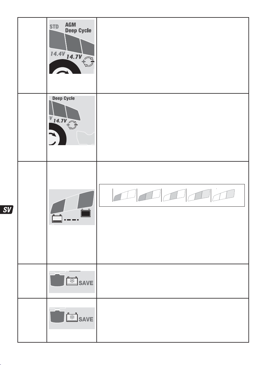
STEG 1
Lågspännin-
gsstart
(Batt. ≥ 0,5
V)
1a
1b
STD: Batterispänningskontroll – STD-läge aktiveras om den anslutna
batterispänningen är minst 0,5 V.
Batterier som mäter under 2 V vid anslutning kommer att gå vidare till
STEG 2 för ”Pulsladdning” som omfattar ett kortslutningstest av batteriet.
STEG 2
Pulsladdning
STEG 3
TESTA före
laddning
STEG 4
Avancerad
RÄDDNING
- sulfaterat
batteri
STEG 5
RECUPERO
Impulsi
e
l
c
t
e
S
1b
2
e
c
t
TEST-lysdiod
#6: GRÖN
#7: GUL
#8: RÖD
7
8
TEST
Lysdiod #3 : RÖD
3
Lysdiod #3 : RÖD
3
Batterier som mäter 2 V eller mer går direkt till STEG 3.
Pulsladdning - LED #8 (röd) blinkar: OptiMate 7 Ampmatic skickar en
testsignal för att se om batteriet går att återställa.
Om spänningen överstiger 2 V och inga kortslutningar har identifierats så kommer
programmet att fortsätta till STEG 3.
Om blinkandet fortsätter så kan följande lägen hindra laddningsprogrammet från att gå
vidare:
1) Fordonets kretsar är fortfarande anslutna till batteriet.
OBS!: Om batteriet som laddas har låg spänning eller befinner sig i ett
5
sulfaterat tillstånd, så ska man först koppla bort batteriet från fordonets
kretsar för bästa testresultat och effektiv laddning.
2) Batteriet har flera kortslutna celler. Batteriet har permanenta skador och bör bytas ut.
TEST-lysdiod 6/7/8 indikerar batteriets skick före laddning. Använd tabellen nedan eller
på sidan 2 för att matcha TEST-lysdiodernas indikeringar mot en beräknad laddningsgrad
(SOC%).
0
6
Beslut som tas under testet:
STEG 7 OPTIMERING – kortaste laddningstiden baseras på testresultatet. Tiden varierar
från 10 minuter för ett batteri med en laddningsgrad på 80 % eller högre till 120 minuter
för ett batteri med en laddningsgrad på 40 % eller lägre.
Omgivningstemperaturen mäts i syfte att bestämma laddningsspänningsparametrar.
Laddningen påbörjas efter 10 sekunder.
Urladdningsgrad fastställs; ett batteri med minst 60% laddning går direkt till STEG 6 och
kraftigt urladdade batterier går till STEG 4 och 5. Kraftigt urladdade batterier kommer att
genomgå ett längre test (upp till 12 timmar) under STEG 8.
Laddningstid: högst 2 timmar.
Utspänningen ökar till maximalt 22V med strömbegränsning till 0,4A, men endast då
ingen fordonselektronik har detekterats, annars går laddaren vidare till nästa steg.
VIKTIGT! Läs avsnittet URLADDADE OCH SKADADE BATTERIER nedan.
Laddningstid: Minst 15 minuter, högst 2 timmar
Återställningsladdning sker. Ström levereras i pulser för att förbereda batteriet för att
kunna ta normal laddning.
Det här läget är speciellt effektivt för återställning av fabriksaktiverade/högprestandabatterier av bly eller cykliska AGM-batterier.
8
0
Aktiveras om batteriet har diagnostiserats som sulfatiserat och inte kan laddas.
Aktiveras om batteriets laddning var 40% eller lägre ELLER om
batteriet har återställts tillräckligt under TURBOÅTERSTÄLLNING.
7
8
7
80 100%604020AGM
6
7
100% 806040STD
6
32
Page 33
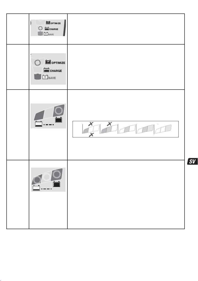
STEG 6 Lysdiod #4 : GUL
4
STEG 7
Lysdiod #5: GUL
OPTIMERING
5
STEG 8
TEST efter
Lysdiod #6
BLINKAR
laddning
6
TEST
STEG 9
Optimate
'365'
underhåll
URLADDADE OCH SKADADE BATTERIER: Om batteriet är djupurladdat (och eventuellt sulfaterat) måste det monteras ur
fordonet och kontrolleras, innan det ansluts till laddaren för återhämtning.
Laddarens TURBO-återställningsläge kan inte aktiveras om det känner av att batteriet fortfarande är anslutet till en elkrets.
Denna elkrets ger nämligen ett lägre elektriskt motstånd än batteriets elkrets. Även om det djupurladdade batteriet inte tas bort för
återställning kommer varken batteri, fordon eller elektronik att skadas. Observera särskilt följande: Batterier som får stå nästan helt
urladdade en längre tid kan få bestående skador i en eller flera celler. Sådana batterier kan bli oerhört varma vid högströmsladdning.
Övervaka batteriets temperatur hela den första timmen och kontrollera det sedan en gång i timmen. Leta efter ovanliga saker som bubblor eller
Lysdiod #6 / 7 / 8 PÅ
6
7
8
TEST
Om batteriet är i gott skick
fortsätter lysdiod #6 (grön) att
lysa.
Undantag: STD-batterier med
flytande elektrolyt och
påfyllningslock har en lägre
spänning vid maximal laddning:
Lysdiod #6 lyser stadigt
tillsammans med lysdiod #7.
Läget CHARGE (Laddning) aktiveras om batteriets laddningsstatus
är 50 % eller högre (enligt testet i STEG 3) eller så snart batteriet
Vilken laddingshastighet som är mest effektiv för det anslutna batteriet fastställs
automatiskt av ampmatic™-programmet för övervakning och styrning av
laddningsström, utifrån batteriets laddningsstatus, skick och elektriska
laddningskapacitet.
ampmatic™-programmet för strömstyrning levererar nu ström i pulser för att
utjämna de enskilda cellerna inne i batteriet och optimera laddningsnivån.
Laddningen bör slutföras inom den kortaste laddningstiden som bestämdes under STEG
3. Om batteriet kräver mer laddning förlängs OPTIMIZE-laddningen upp till de maximala
2 timmarna.
OBS! Laddningstiden förlängs vanligtvis om strömförbrukningen orsakad av de anslutna
kretsarna är högre än förväntat eller om batteriets skick inte är optimalt.
Av säkerhetsskäl finns en laddningsgräns på 72 timmar för STEG 4, 5 och 6.
TEST efter LADDNING: Strömleveransen till batteriet avbryts i 30 minuter** för att
programmet ska kunna avgöra vilken förmåga batteriet har att behålla laddningen.
** OM resultatet i STEG 3 blev RÖD (lysdiod 8) eller RÖD och GUL (lysdiod 7 och 8), vilket
indikerar ett djupurladdat batteri före anslutning, förlängs spänningsgradstestet till 12
timmar för att kontrollera batteriets skick.
Testresultatet (som visas med lysdioderna 6, 7 och 8) justeras i realtid baserat på
uppmätt batterispänning.
0
0
Testet avbryts om lysdiod 8 (röd) tänds. Ett allvarligt problem föreligger om batteriet
inte kan behålla tillräcklig laddning under testperioden. Använd tabellen ”TIDIG VARNING
FÖR BATTERIPROBLEM” på sidan 2 för att tolka lysdiodernas signaler för den beräknade
laddningsgraden (SOC%).
Mer information finns i avsnittet “INFORMATION OM TESTRESULTAT”.
i enlighet med det laddningstillstånd som uppmättes under STEG 8.
Inställd flytspänning: nominellt 13,6V vid 20°C. Flytspänningen regleras omvänt i
förhållande till omgivande temperatur, vilket innebär att spänningen ökas vid lägre
temperatur och minskas vid högre temperatur. Justering: -0,04 V per cell och grad
över eller under 20 °C.
Det vanliga underhållsläget utgörs av laddningsperioder om 30 minuter som omväxlande
följs av viloperioder om 30 minuter. Den här 50-procentiga belastningsgraden förhindrar
förlust av elektrolyt i slutna batterier och minimerar den gradvisa förlusten av vatten i
elektrolyten i batterier med påfyllningslock. Detta ökar avsevärt livslängden på batterier
som används oregelbundet.
Under den 30 minuter långa “flytande laddningen” GES EN LÅGSTRÖMSPULS
KONTINUERLIGT FÖR ATT FÖRHINDRA SULFATERING, vilket ytterligare ökar batteriets
effekt och livslängd.
Om OptiMate upptäcker att batteriets laddning sjunker kommer programmet att
återgå till laddningsläget.
har återställts tillräckligt under STEG 5.
Läget OPTIMIZE startar när spänningen når 14,4V
första gången under CHARGE-läget.
80 100%604020AGM
8
UNDERHÅLLSLADDNING: Lysdiod 6/7/8 lyser konstant
7
8
7
6
7
100% 806040STD
6
33
Page 34

läckande elektrolytvätska, ökad aktivitet i en cell jämfört med andra eller pysande ljud. Om batteriet någon gång blir så varmt att det är
obehagligt att röra vid det, eller om du lägger märke till något annat ovanligt, ska du OMEDELBART KOPPLA BORT LADDAREN.
INFORMATION OM TESTRESULTAT:
1. Om du får ett annat testresultat än grön LED #6 (eller grön LED #6 och gul LED #7 tillsammans om det är ett STD-batteri med
påfyllningslock) bör du koppla bort batteriet från det elsystem som det stöder och sedan ansluta OptiMate-laddaren igen. Blir
testresultat bättre nu antyder det att effektförlusterna delvis beror på ett elektriskt problem i elsystemet, och inte i själva batteriet.
Består det dåliga resultatet rekommenderar vi att du lämnar in batteriet för närmare granskning på en serviceverkstad som har
tillgång till professionell utrustning.
2. Om den röda LED #8 lyser ensam, eller om den gula LED #7 och den röda LED #8 lyser samtidigt (eller om den gula LED-lampan
lyser ensam när ett slutet batteri används), tyder det på ett allvarligt fel. Den röda/den gula + röda LED-lampan indikerar att batteriet
inte kan hålla spänningen efter att det laddats, eller att det inte gick att återställa batteriet trots flera försök. Detta kan bero på ett fel
i själva batteriet, till exempel en kortsluten cell eller total sulfatering. Om batteriet fortfarande är anslutet till det elsystem som det
stödjer kan den röda LED #8 också indikera strömförluster till följd av dåliga kablar, strömslukande tillbehör eller angripna
strömbrytare eller kontakter. En plötslig belastning medan laddaren är ansluten kan också leda till att batterispänningen minskar
betydligt.
3. GODA TESTRESULTAT, men batteriet kan inte leverera tillräckligt med ström: a) Permanenta skador inuti batteriet kan orsaka en
omfattande självurladdning som inte upptäcks inom testperioden på 12 timmar. Koppla bort batteriet från OptiMate-laddaren.
Återanslut batteriet när det gått minst 48 timmar och läs av resultatet under FÖRBEDÖMNINGSTESTET. b) Långvariga vibrationer kan
orsaka hårfina sprickor i kontakterna mellan cellerna i batteriet. Ett högt spänningsbortfall inträffar endast när effektbehovet är högt
(t.ex. när motorn dras igång).
LÅNGSIKTIGT BATTERIUNDERHÅLL: OptiMate kan bevara ett batteri i gott skick i flera månader i taget. Du bör kontrollera att
kopplingen mellan laddaren och batteriet är korrekt minst varannan vecka och, om det är ett batteri med påfyllningslock på varje
cell, bör du även koppla från batteriet från laddaren, kontrollera elektrolytnivån och vid behov fylla på cellerna (med destillerat
vatten, INTE syra) och sedan återansluta dem. Ta alltid hänsyn till de SÄKERHETSVARNINGAR som beskrivs ovan när du hanterar
eller befinner dig i närheten av batterier.
STRÖMSPARLÄGE NÄR LADDAREN ÄR ANSLUTEN TILL VÄXELSTRÖMSFÖRSÖRJNINGEN:
Strömomvandlaren går över till strömsparläge när laddaren inte är ansluten till något batteri. Det gör att den drar mycket lite ström:
mindre än 0,5 W, vilket motsvarar en energiförbrukning på 0,012 kWh per dag. När ett batteri är anslutet till laddaren beror
energiförbrukningen på den ström som batteriet och det anslutna fordonet/de elektroniska kretsarna kräver. När batteriet har
laddats och laddaren har övergått till läget långvarig underhållsladdning (vilket håller batteriet fulladdat) uppgår den totala
energiförbrukningen till ungefär 0,024 kWh, eller ännu mindre, per dag.
INSKRÄNKT GARANTI
TecMate (International) NV, Sint-Truidensesteenweg 252, B-3300 Tienen, Belgien, utfärdar denna garanti till den ursprungliga
köparen av produkten. Garantin kan inte överlåtas. Denna batteriladdare har av TecMate (International) försetts med en garanti
som gäller i tre år från och med det datum den köpts hos en återförsäljare. Garantin omfattar materialfel och tillverkningsfel.
Om något av nämnda fel upptäcks kommer enheten att repareras eller bytas ut enligt tillverkarens önskemål. Köparen måste
överlämna enheten tillsammans med ett köpebevis (se "NOTERA") och förbetalda transport- eller portokostnader till tillverkaren
eller en auktoriserad återförsäljare. Garantin gäller inte om produkten används felaktigt eller vårdslöst. Den gäller heller inte om
produkten reparerats av någon annan än tillverkaren eller en auktoriserad återförsäljare. Denna garanti är den enda giltiga och
den omfattar inga implicerade garantikrav, inklusive garantikrav för följdskador.
DETTA ÄR DEN ENDA GÄLLANDE GARANTIN OCH TILLVERKAREN VARKEN ÅTAR SIG ELLER AUKTORISERAR NÅGON ANNAN ATT
ÅTA SIG ELLER UPPRÄTTA NÅGRA SKYLDIGHETER GENTEMOT PRODUKTEN FÖRUTOM DENNA GARANTI. DINA LAGLIGA
RÄTTIGHETER PÅVERKAS INTE.
NOTERA: Se www.tecmate.com/warranty eller kontakta warranty@tecmate.com
OptiMate 7 och namnger av andra produkter som nämns i dessa anvisningar liksom BatteryMate, TestMate och TestMatemini,
är registreringsvarumärken av TecMate International NV.
Mer information på TecMate produkter kan finnas på www.tecmate.com.
34
Page 35

AUTOMATICKÁ ÚDRŽBOVÁ NABÍJEČKA PRO 12V OLOVO/KYSELINOVÉ BATERIE.
NEPOUŽÍVEJTE PRO NICD, NIMH, LI-ION NEBO BATERIE, KTERÉ SE NEDAJÍ NABÍJET.
DŮLEŽITÉ: PŘED POUŽITÍM NABÍJEČKY SI PŘEČTĚTE NÁSLEDUJÍCÍ POKYNY
Toto zařízení není určeno pro používání osobami (včetně dětí) se sníženými fyzickými, senzorickými
nebo duševními schopnostmi nebo s nedostatkem zkušeností a znalostí, pokud nepracují pod dozorem
nebo pokud od osoby zodpovědné za jejich bezpečnost neobdržely pokyny týkající se používání
zařízení. Děti by měly být pod dozorem, aby si nemohly s tímto zařízením hrát.
BEZPEČNOSTNÍ VAROVÁNÍ A POZNÁMKY: Baterie uvolňují TŘASKAVÉ PLYNY – v blízkosti baterie nesmí být otevřený
oheň nebo zdroj jiskření. Před zapojením nebo odpojením stejnosměrného proudu/připojení baterie odpojte zdroj střídavého
proudu. Bateriová kyselina je silná žíravina. Noste ochranný oděv a ochranné brýle, aby nedošlo ke kontaktu s kyselinou. V případě
náhodného kontaktu místo okamžitě omyjte mýdlem a vodou. Zkontrolujte, zda nejsou uvolněné kolíky baterie; pokud ano, nechte
baterii odborně prohlédnout. Pokud jsou kolíky baterie zkorodované, vyčistěte je měděným kartáčem; pokud jsou mastné nebo
špinavé, vyčistěte je hadrem namočeným v čisticím prostředku. Nabíječku používejte pouze pokud jsou vstupní a výstupní vodiče a
konektory v dobrém, nepoškozeném stavu.
výrobce, jeho autorizovaného servisního zástupce nebo v kompetentní dílně, aby nevzniklo
nebezpečí.
oxidací nebo vnitřním elektrickým zkratem se záruka nevztahuje. Nabíječku udržujte během nabíjení baterie v dostatečné
vzdálenosti, aby nedošlo ke znečištění nebo styku s kyselinou nebo kyselými výpary. Pokud používáte nabíječku ve vodorovné
poloze, položte ji na tvrdý, hladký povrch, ale NIKDY na plast, textil nebo kůži. Použijte připravené otvory na spodní straně krytu k
upevnění nabíječky k jakémukoli vhodnému, pevnému svislému povrchu.
Při používání i skladování chraňte nabíječku před kyselinou, kyselými výpary a vlhkostí. Na poškození vzniklé korozí,
VYSTAVENÍ TEKUTINÁM: Nabíječka je navržena tak, aby odolala styku s kapalinami náhodně rozlitými nebo rozstříknutými na
pouzdro shora nebo mírnému dešti. Nedoporučuje se ponechávat nabíječku dlouhodobě vystavenou dešti, což by rovněž mělo za
následek zkrácení životnosti. Na poruchy nabíječky v důsledku oxidace způsobené případným proniknutím tekutiny k elektronickým
součástkám, svorkám nebo zástrčkám, se záruka nevztahuje.
PŘIPOJENÍ NABÍJEČKY K BATERII
1. Před připojením nebo odpojením stejnosměrného proudu / připojení baterie odpojte zdroj
střídavého proudu.
2. Pokud nabíjíte baterii ve vozidle pomocí svorek baterie ujistěte se před připojením, že je možné svorky baterie bezpečně umístit
tak, aby nenarušily okolní vedení, kovové potrubí nebo rám. Připojení provádějte v tomto pořadí:
baterie, který není připojen k rámu (obvykle kladný), pak připojte další svorku baterie (obvykle
zápornou), která je připojena k rámu tak, aby nezasahovala do vedení baterie nebo paliva.
Odpojujte vždy v opačném pořadí.
3. Pokud nabíjíte baterii svorkami mimo vozidlo, umístěte ji v dobře větraném prostoru. Připojte nabíječku k baterii: ČERVENOU
svorku ke KLADNÉMU (POS, P nebo +) pólu a ČERNOU svorku k ZÁPORNÉMU (NEG, N nebo -) pólu. Dbejte na to, aby byla
připojení pevná a bezpečná. Dobrý kontakt je důležitý.
4. Pokud je baterie silně vybitá (a tvoří se sulfidy), vyjměte baterii z vozidla a před dalším připojením k nabíječce baterii
zkontrolujte. Vizuálně zkontrolujte mechanické závady na baterii, jako např. vypouklé nebo prasklé pouzdro, nebo známky
úniku elektrolytu. Pokud jsou na baterii krytky plnicích otvorů a destičky v článcích jsou viditelné zvenku, pečlivě baterii
prohlédněte a pokuste se zjistit, zda se některé články liší od ostatních (např. bílý povlak mezi destičkami, kontakty destiček).
Pokud jsou patrné mechanické vady, nepřipojujte nabíječku k baterii, nechte baterii odborně prohlédnout.
5. Pokud je baterie nová, přečtěte si před připojením nabíječky pečlivě návod k obsluze dodaný výrobcem. Pokud se provádí,
pečlivě a přesně dodržujte pokyny pro plnění kyseliny.
PŘECHOD K NABÍJENÍ:
DOBA NABÍJENÍ : Doba nabíjení zcela vybité, ale jinak nepoškozené baterie: u 100Ah 12V baterie by neměla trvat déle než 12
hodin, než přejde ke kontrole samovybíjení. Silně vybité baterie se mohou nabíjet podstatně déle a úplného nabití nemusí být v
takovém případě dosaženo ani během 72hodinového bezpečnostního limitu.
: Nabíjecí napětí je regulováno nepřímo úměrně podle okolní teploty, tj. napětí se zvyšuje s nižší teplotou a snižuje s vyšší
teplotou. Nastavení: -0,004 V / článek / °C nad nebo pod 20 °C (68 °F).
ZAPNUTO: LED #1 - Potvrzuje, že nabíječka je napájena ze střídavého zdroje.
Indikace VYSOKÉ a NÍZKÉ intenzity: LED č. 1 „ZAPNUTO“ bude zřetelně indikovat, že do baterie je dodáván proud.
LED č. 1 „ZAPNUTO“ bude svítit méně intenzivně a signalizuje tak úsporný „EKO“ režim. Tento stav nastane, když není připojena
žádná baterie, nebo když je baterie připojena a program se nachází v režimu testování uchování napětí, nebo v „klidové“ fázi režimu
údržby nabití.
OCHRANA PROTI OBRÁCENÉ POLARITĚ: LED #2 - Svítí při nesprávném připojení baterie. Nabíječka je elektronicky chráněna, takže
nedojde k jejímu poškození a výstup se obnoví až po správném připojení
Pokud je vstupní kabel poškozen, nechte jej neprodleně vyměnit u
Nejprve připojte pól
.
CZ
BEZPEČNOST
35
Page 36
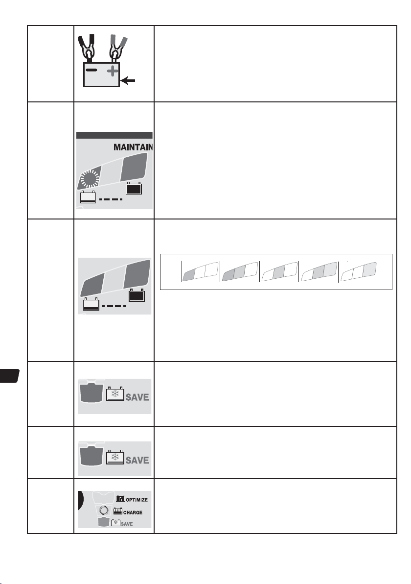
KROK 1
Low Volt
START -
Bat ≥ 0.5V
STD: Kontrola napětí baterie – OptiMate 7 Ampmatic se automaticky
aktivuje, když je napětí připojené baterie alespoň 0,5 V.
Baterie snižším napětím než 2V na připojení přejdou na KROK2 pro „Impulzní
probuzení“, který zahrnuje test, jestli baterie není zkratovaná.
V
Baterie snapětím 2V avíce přejdou přímo na KROK3.
CZCZ
KROK2
Pulse
wake up
KROK3
TEST před
nabitím
KROK 4
pokročilá
ZÁCHRANA
–
sulfatovaná
baterie
KROK 5
Impulzní
ZÁCHRANA
KROK 6
NABÍJENÍ
LED č.8 BLIKÁ
6
7
8
TEST
TESTOVACÍ LED
6 : ZELENÁ
7 : ŽLUTÁ
8 : ČERVENÁ
7
8
TEST
LED č.3 : ČERVENÁ
3
LED č.3 : ČERVENÁ
3
LED č.4 : ŽLUTÁ
4
Impulzní probuzení – bliká LED č.8 (červená): Přístroj OptiMate 7
Ampmatic zavádí testovací signál scílem zjistit, jestli je baterie schopná
zotavení.
Pokud je napětí trvale vyšší než 2V anebyl detekován žádný zkrat, program přede na
KROK3.
Pokud blikání pokračuje, mohou vprogramu nabíjení bránit následující podmínky:
1) Obvod vozu zůstává připojený kbaterii.
POZNÁMKA: Pokud je nabíjená baterie ve stavu nízkého napětí nebo
vsulfatovaném stavu, nejvyššího účinku nabíjení anejlepších výsledků
testů dosáhnete, když baterii před nabíjením odpojíte od obvodu vozidla.
2) Baterie má několik zkratovaných článků. Baterie vykazuje trvalé poškození aměla
by být vyměněna.
TESTOVACÍ LED č.6/7/8označují stav baterie před nabíjením. V následující tabulce je
uveden vztah mezi LED indikací TESTU a odhadovaným stavem nabití v procentech
(SOC%). Nabíjení bude zahájeno za 10 sekund.
0
6
Rozhodnutí přijatá vprůběhu testu:
Nabíjecí napětí vprůběhu KROKU6 a7 je upraveno podle naměřené okolní teploty.
KROK7 – OPTIMALIZACE: Podle výsledku testu se nastaví minimální čas nabíjení, od
10minut pro baterii nabitou na 80% avíce, až po 120 minut pro baterii nabitou na
40% améně.
Je určena míra vybití: baterie nabitá na 60% avíce přejde přímo na KROK6, kde (jako
hodně vybitá baterie) přejde na KROK4 a5. Hodně vybité baterie projdou při KROKU8
delším testováním (až 12hodin).
Doba nabíjení: maximálně 2 hodiny.
Výstupní napětí se zvyšuje do max. hodnoty 22 V s proudem omezeným na 0,4 A, ale
pouze v případě, že není rozpoznána žádná elektronika vozidla, jinak přejde přímo na
KROK 5. DŮLEŽITÉ: Přečtěte si dále uvedenou část ZANEDBANÉ, SILNĚ VYBITÉ
BATERIE.
DOBA NABÍJENÍ: min. 15 minut, max. 2 hodiny.
Proud je dodáván v impulzech, aby se baterie připravila na normální nabíjení.
Tento krok je účinný zejména při oživení továrně aktivovaných / „vysoce výkonných“
čistě olověných baterií nebo AGM baterií s cyklickými články.
Program pro monitorování nabíjecího proudu a řízení ampmatic™ automaticky určí
nejúčinnější nabíjecí proud pro připojenou baterii podle jejího stavu nabití, stavu a
kapacity.
8
0
Rozsvítí se, když je baterie diagnostikována jako sulfatovaná,
Rozsvítí se, když byl stav nabití baterie 40 % nebo méně, NEBO se baterie
úspěšně zotavila během POKROČILÉ ZÁCHRANY.
Rozsvítí se, když byl stav nabití baterie 50 % nebo vyšší (dle testu v
KROKU 3), nebo když se baterie úspěšně zotavila během KROKU 5.
7
8
neschopná přijmout nebo udržet napětí.
7
80 100%604020AGM
6
7
100% 806040STD
6
36
Page 37
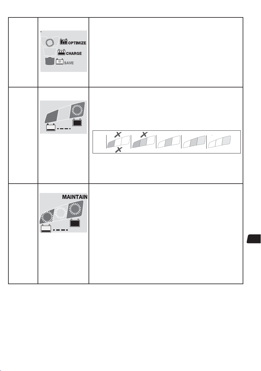
KROK 7
OPTIMALIZACE
KROK 8
TEST po
nabití
KROK 9
Údržba
OptiMate
'365'
LED #5 : ŽLUTÁ
5
LED #6 BLIKÁ
6
TEST
LED č.6 / 7 / 8 SVÍTÍ
6
7
8
TEST
U baterií v dobrém stavu
zůstane LED č. 6 (zelená)
svítit.
Výjimka: STD baterie s
mokrými články s krytkami
plnicího otvoru mají při
úplném nabití nižší napětí:
LED č. 6 zůstane svítit
spolu s LED č. 7.
Rozsvítí se, když napětí během režimu NABÍJENÍ poprvé dosáhne
hodnoty 14,4 V.
Program pro řízení proudu ampmatic™ nyní dodává proudové impulzy, aby
vyrovnal jednotlivé články baterie a optimalizoval úroveň nabití.
POZNÁMKA: Doba nabíjení se obvykle prodlouží, jestliže odběr proudu připojeným
obvodem je vyšší než se očekávalo nebo stav baterie není optimální.
TIP: Pokud je nabíjená baterie ve stavu nízkého napětí nebo v sulfatovaném stavu,
nejvyššího účinku nabíjení a nejlepších výsledků testů dosáhnete, když baterii před
nabíjením odpojíte od obvodu vozidla.
Z bezpečnostních důvodů je pro KROKY 4, 5 a 6 stanoven limit celkové
doby nabíjení72 hodin.
TEST po nabití: Dodávka proudu do baterie je přerušena na dobu 30
minut**, aby mohl program určit schopnost baterie udržet napětí.
** POKUD byl výsledek v KROKU 3 ČERVENÁ (LED č. 8) nebo ČERVENÁ A ŽLUTÁ (LED
č. 7 a 8), který označuje silně vybitou baterii), test udržení napětí se prodlouží na 12
hodin, aby byl potvrzen dobrý stav baterie.
Výsledek TESTU (indikovaný LED č. 6, 7, 8) je upravován v reálném čase podle
změřeného napětí baterie.
0
8
0
TEST se přeruší, když se rozsvítí LED č. 8 (červená). Závažný problém nastane, když
baterie během tohoto testu udržení napětí nedokáže udržet dostatečné napětí. Ve výše
uvedené tabulce je uveden vztah mezi LED indikací TESTU a odhadovaným stavem
nabití v procentech (SOC%). Další informace najdete v části „POZNÁMKY K VÝSLEDKŮM
TESTU“.
UDRŽOVACÍ NABÍJENÍ: LED č. 6 / 7 / 8 svítí
Nastavení plovoucího napětí: jmenovité 13,6 V při 20 °C (68 °F) Plovoucí napětí je
regulováno nepřímo úměrně podle okolní teploty, tj. napětí se zvyšuje s nižší
teplotou a snižuje s vyšší teplotou.
Nastavení: -0,004 V / článek / °C nad nebo pod 20 °C (68 °F).
Režim údržby STD baterie sestává z 30minutových intervalů plovoucího nabíjení
střídajících se s 30minutovými „klidovými“ intervaly, kdy není dodáván žádný nabíjecí
proud. Tento „50% pracovní cyklus“ zabraňuje ztrátě elektrolytu u uzavřených baterií a
minimalizuje postupný úbytek vody z elektrolytu u baterií s krytkami plnicího otvoru,
čímž významně přispívá k optimalizaci životnosti nepravidelně nebo sezónně
používaných baterií.
Během „plovoucího nabíjení“ je trvale DODÁVÁN NÍZKÝ PROUDOVÝ IMPULZ, ABY SE
ZABRÁNILO SULFATACI, což dále zvyšuje výkon a prodlužuje životnost baterie.
Když nabíječka OptiMate zjistí, že baterie ztrácí napětí, program se vrátí ke kroku
NABÍJENÍ.
v závislosti na stavu nabití naměřeném během KROKU 8.
7
8
7
80 100%604020AGM
6
7
100% 806040STD
6
CZ
ZANEDBANÉ, SILNĚ VYBITÉ BATERIE: Pokud je baterie silně vybitá (případně sulfatovaná), vyjměte baterii z
nebo ze zařízení a před připojením k nabíječce ji zkontrolujte.
vozidla
Režim oživení nabíječky TURBO se nespustí, pokud rozpozná, že je baterie stále připojena k obvodu, který efektivně poskytuje nižší
elektrický odpor než vlastní baterie. Avšak i když silně vybitou baterii nevyjmete a neoživíte ji, nedojde k poškození baterie ani elektroniky
vozidla nebo zařízení. Věnujte zvláštní pozornost následující informaci: Pokud necháte baterii dlouhou dobu silně vybitou, může se
trvale poškodit jeden nebo více článků. Takové baterie se mohou při nabíjení vysokým proudem nadměrně zahřívat.
Během první hodiny sledujte teplotu baterie, pak každou hodinu. Kontrolujte nezvyklé známky, jako např. bublání nebo únik elektrolytu,
zvýšenou činnost jednoho článku v porovnání s ostatními nebo syčivé zvuky. Kdykoli je baterie příliš horká, abyste se jí mohli dotknout,
nebo zaznamenáte-li nezvyklé příznaky, NABÍJEČKU OKAMŽITĚ ODPOJTE..
POZNÁMKY K VÝSLEDKŮM TESTU:
1.Pokud je výsledek testu jiný než že svítí zelená kontrolka č. 6 (nebo svítí společně zelená kontrolka č. 6 a žlutá č. 7 u typu STD s krytkami
plnicího otvoru), odpojte baterii od elektroinstalace, kterou podporuje a znovu připojte nabíječku OptiMate. Pokud je nyní výsledek testu
37
Page 38

lepší, ukazuje to, že ztráty energie jsou zčásti zapříčiněny problémem v elektrickém systému a ne baterií. Pokud i nadále vykazuje
špatný výsledek, doporučujeme odnést baterii do odborné servisní dílny vybavené profesionálním zařízením, kde provedou
podrobnější šetření.
Pokud svítí samostatně červená LED č. 8 nebo společně žlutá LED č. 7 a červená LED č. 8 (nebo svítí samostatně žlutá LED u
2.
uzavřené baterie), znamená to závažný problém. Červená / žlutá a červená LED znamená, že po nabití napětí baterie klesá, nebo se
přes všechny pokusy o oživení nepodařilo baterii oživit. Může to být způsobeno závadou baterie, například zkratovaným článkem
nebo celkovou sulfatací, nebo, v případě, kdy je baterie stále připojená k elektrickému systému, který podporuje, může svítící
červená LED č. 8 signalizovat ztrátu proudu narušeným zapojením nebo zničeným spínačem nebo kontaktem, nebo příslušenstvím v
obvodu, které spotřebovává proud. Náhlé zatížení ve chvíli, kdy je nabíječka připojená, může rovněž způsobit znatelný pokles napětí
baterie.
DOBRÝ VÝSLEDEK TESTU, ale baterie není schopna dodávat dostatečné napájení: a) Trvalé poškození baterie může způsobit
3.
nadměrné samovybíjení, které nebylo během 12hodinového intervalu testu detekováno. Odpojte baterii od nabíječky OptiMate.
Nejméně po 48 hodinách ji znovu připojte a zkontrolujte výsledek TESTU PŘED NABÍJENÍM; b) Dlouhodobé vibrace můžou způsobit
vlasové trhliny ve vnitřním propojení článků baterie. Velká ztráta napětí přes takové praskliny nastane pouze pokud je požadavek na
odběr vysoký (např. startování motoru).
ÚDRŽBA BATERIE V DELŠÍM OBDOBÍ: OptiMate udrží nabitou baterii, která je v dobrém stavu, po několik měsíců.
Přinejmenším každé dva týdny zkontrolujte, zda je v pořádku zapojení mezi nabíječkou a baterií, a u baterií s krytkami plnicího
otvoru na jednotlivých článcích odpojte baterii od nabíječky, zkontrolujte hladinu elektrolytu, v případě potřeby ji doplňte
(destilovanou vodou, NIKOLI kyselinou) a baterii znovu připojte. Při manipulaci s bateriemi nebo v jejich blízkosti vždy dodržujte výše
uvedená BEZPEČNOSTNÍ UPOZORNĚNÍ..
EKO ÚSPORNÝ REŽIM PŘI PŘIPOJENÍ NABÍJEČKY KE ZDROJI STŘÍDAVÉHO PROUDU:
Když není nabíječka připojena k baterii, měnič se přepne do režimu EKO; to zaručuje velmi nízkou spotřebu, méně než 0,5 W, což
představuje spotřebu 0,012 kWh/den. Když je k nabíječce připojená baterie, závisí spotřeba na skutečné dodávce do baterie a na
tom, zda je připojena k vozidlu / elektronické soustavě obvodů. Po nabití baterie, kdy je nabíječka v režimu dlouhodobé údržby
baterie (udržuje baterii 100% nabitou), se celková spotřeba odhaduje na 0,024 kWh / den nebo méně.
OMEZENÁ ZÁRUKA
Společnost TecMate (International) SA, Sint-Truidensesteenweg 252, B-3300 Tienen, Belgie, poskytuje tuto omezenou záruku
původnímu kupci tohoto výrobku. Tato omezená záruka je nepřevoditelná. Společnost TechMate (International) poskytuje
záruku na vady materiálu a výrobní vady této nabíječky baterií na dobu tří let od data nákupu u prodejce. Pokud se vyskytne
závada, výrobce posoudí, zda jednotku opraví nebo vymění. Kupující je povinen na vlastní náklady zaslat jednotku spolu s
dokladem o koupi (viz POZNÁMKA) výrobci nebo jeho autorizovanému zástupci. Tato omezená záruka zaniká, pokud se výrobek
nepoužívá v souladu s návodem, nakládá se s ním nešetrně nebo byla provedena oprava jinde než v továrně nebo u
autorizovaného zástupce. Výrobce neposkytuje žádnou jinou záruku, pouze tuto omezenou záruku a výslovně vylučuje jakoukoli
nevyjádřenou záruku včetně záruky na následná poškození.
JEDNÁ SE O JEDINOU UZNANOU OMEZENOU ZÁRUKU A V¯ROBCE NEPŘEBÍRÁ ANI NEPOVĚŘUJE ŽÁDNOU JINOU OSOBU, ABY
PŘEVZALA NEBO UZAVÍRALA VE VZTAHU K V¯ROBKU JINÉ ZÁVAZKY, NEŽ JE TATO OMEZENÁ ZÁRUKA. VAŠE ZÁKONNÁ PRÁVA
TÍM OVLIVNĚNA NEJSOU.
POZNÁMKA: Podrobnosti naleznete na www.tecmate.com/warranty.
OptiMate 7 a názvy ostatních výrobků péče o baterie uvedené v tomto návodu, jako např. BatteryMate, TestMate a TestMate
mini, jsou registrovanými ochrannými známkami společnosti TecMate International NV..
CZ
Další informace o výrobcích společnosti TecMate naleznete na www.tecmate.com.
38
Page 39

PRODUCT INFORMATION
Certification / Conformity
Holder: TecMate (International ) S.A. , B-3300 Tienen, Belgium
Issued by: TUV SUD Product Service GmbH, DE (Safety and EMC)
Safety (CE-LVD) : Low voltage directive 2006/95/EC; EN 60335-2-29:2004/A2:2010;
EN 60335-1:2012/A11:2014; EN 62233:2008
Safety (NRTL) : UL 1236:R2011; CAN/CSA C22.2 no. 107.2-01 (R2011)
Safety (SAA) : AS/NZS 60335.2.29:2004 Inc A1-2; AS/NZS 60335.1.2011 Inc A1
EMC (CE) : EMC Directive 2004/108/EC; EN55014-1/A2:2011; EN55014-2/
A2:2008; EN61000-3-2/A2:2009; EN6100-2-2:2013
EMC (NRTL) : FCC CFR Title 47 Part 15 Subpart B
Efficiency - BC
mark
(California
Energy Commision)
CEC-400-2012-011-CMF; 10 CFR Section 430.23 (aa) Appendix Y to
Subpart B of Part 430.
Tests by: Mantek International Canada Inc, Oakville ON, Canada.
Listed models: TM25x, TM26x
Energy usage: Not charging: P < 0.5W Long term maintenance: P < 0.5W ( < 0.012
kWh / day, < 4.4 kWh / year )
Mechanical
IP rating IP54
t° operating range -40°C <-> 40°C / -40°F <-> 104°F
Weight (packed) 1.2kg (1.5kg) / 2.64lbs (3.3 lbs)
Size without cable 240 x 75 x 120mm / 9.45" x 2.95" x 4.72"
Cable Length Input: 183cm / 72" Output: 183cm / 72"
Wall mount 4 mount positions
Accessories O-11 Weatherproof battery cable; O-04 battery Clips.
Gold plated SAE Hi Power connectors
Electrical (additional)
Reverse drain Id < 0.5mA
Max input rating 90 - 264Vac 47-63Hz
Output volt range 0.5V - 14.4V @ 10A; 14.5V - 22V @ 0.4A
Protection Input AC fuse: 3A 250V (non accessible)
Protection output AUTOMATIC: reverse polarity; no output if no battery is connected;
limited output current (1A max).
Origin
Design copyright
& trademark
TecMate (International) S.A., B-3300 Tienen, Belgium
www.tecmate.com
Page 40
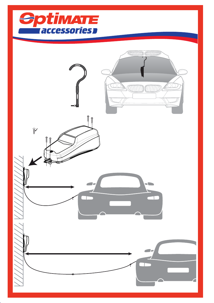
OptiMate HOOK
TS-252
Ø ≤ 4.5mm / 3/16”
L ≥ 25mm / 1”
4x
optimate1.com
STD
2m / 6ft max.
OptiMate CABLE
+ O-23 Extender
+ O-13 / O-23
(10 Amp - 4.6m / 15ft)
6.4m / 15ft max.
6.6m / 21ft
 Loading...