

TecMate OptiMATE Lithium TM290, OptiMATE Lithium TM294, OptiMATE Lithium TM291, OptiMATE Lithium TM298 Instructions For Use Manual
Page 1
PT
CZ
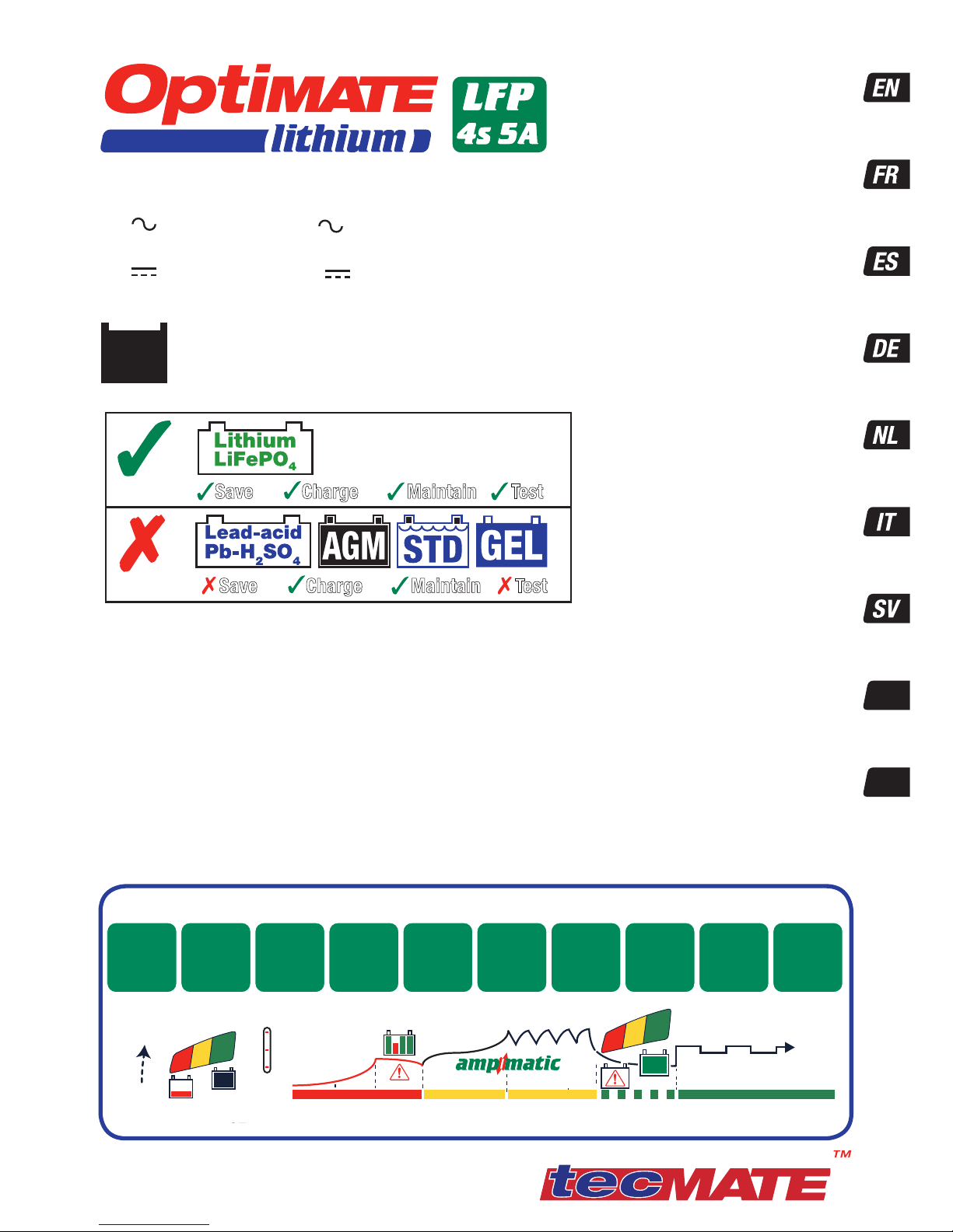
Automatic charger for 12.8V LiFePO4 batteries
Chargeur automatique pour batteries 12.8V LiFePO4
Cargador automático para baterías 12.8V LiFePO4
Automatische Ladegerät für 12.8V LiFePO4 Batterien
Automatische lader voor 12.8V LiFePO4 accu’s
Caricabatterie automatico per batterie 12.8V LiFePO4
Carregador automático para baterias de 12.8V LiFePO4
Automatisk diagnostisk laddare för 12.8V LiFePO4batterier
Automatická diagnostická nabíječka pro 12,8v baterie
LiFePO
4
MODEL: TM290 (EU), TM291 (US), TM294 (UK),
TM298 (AU)
AC: 100 – 240V 50-60Hz
0.85A @ 240V / 1.5A @ 100V
DC: 60W ¨ 12V 5A
Thermally adjusted
INSTRUCTIONS FOR USE
IMPORTANT: Read completely
before charging
MODE D’EMPLOI
IMPORTANT: à lire avant
d’utiliser l’appareil
MODO DE EMPLEO
IMPORTANTE: a leer antes
de utilizar el aparato
ANWENDUNGSVORSCHRIFTEN
WICHTIG: Vollständig vor der
Benutzung lesen
GEBRUIKSAANWIJZING
BELANGRIJK: Lees volledig
voor gebruik
ISTRUZIONI PER L’USO
IMPORTANTE: da leggere prima
di utilizzare l’apparecchio
INSTRUKTIONER VIKTIGT: läs
följande fullständiga instruktioner för användningen innan
du använder laddaren
INSTRUÇÕES DE UTILIZAÇÃO
IMPORTANTE: Ler antes de
utilizar.
INSTRUKCE PRO POUŽIT.
DŮLEŽIT: Přečtěte si pozorně
před použit.m
Save Charge Maintain Test
Save Charge Maintain Test
1 x 12.8V (4 x 3.2V cells) LiFePO
4
Lithium Iron Phosphate
2.5 - 100Ah (charge within 24 hours)
+-
10 STEPS
TM29x-IN1-170306
copyright @ 2017 TecMate International
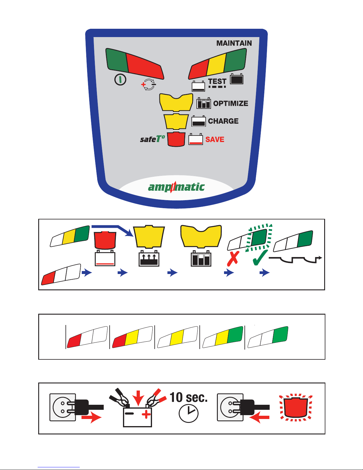
10
OptiMate
maintenance
9
TEST after
CHARGE
1
Low Volt
Start (0.5V)
2
TEST before
charge
3
Temperature
check
4
Ultra LOW
VOLT SAVE
5
LOW VOLT
SAVE /
cellmonitoring
6
TEST -
cell damage
7
Cell-balancing
CHARGE
8
OPTIMIZE
0.5V
13.6V
14.4V
4&5.SAVE 6.TEST 7.CHARGE 8.OPTIMIZE 9.TEST 10. MAINTAIN
1.START 2.TEST 3.TEMP
24-7-365
°C/°F
40
-20
0
104
32
-4
Page 2
2
1
8
7
6
5
4
3
TEST > LEDs
TEST
30m - 12h
MAINTAIN
365
CHARGE
24h max
SAVE
15m - 4h
OPTIMIZE
10m - 12h
TEST
10s
6
7
8
3
4
5
6
6
LED PANEL
8
7
6
90 100%603010%
13.3V 13.6V+ 13.13V13.00V12.80VV
8
7
7
6
0
10V
3
BMS RESET
PROGRAM > LEDs
2
Page 3
3
IMPORTANT SAFETY
INSTRUCTIONS FOR CANADA & USA
THIS PORTION OF THE MANUAL CONTAINS IMPORTANT SAFETY INSTRUCTIONS FOR THE OptiMate
LITHIUM BATTERY CHARGER. IT IS OF THE UTMOST IMPORTANCE THAT EACH TIME, BEFORE
USING THE CHARGER, YOU READ AND EXACTLY FOLLOW THESE INSTRUCTIONS. SAVE THESE
INSTRUCTIONS.
AUTOMATIC CHARGER ONLY FOR 12.8V LIFEPO
4
(LITHIUM IRON PHOSPHATE ) BATTERIES.
A rechargeable LIFEPO
4
battery should comply with IEC62133*.
DO NOT USE FOR NiCd, NiMH, Lead-Acid or any other type of Li-Ion or
NON-RECHARGEABLE BATTERIES.
*IEC62133 - Safety requirements for portable sealed secondary cells containing alkaline or other
non acid electrolytes and for batteries made from them, for use in portable applications.
1. CAUTION : CLASS II APPLIANCE. DO NOT CONNECT TO GROUND.
2. For indoor use only. Do not expose charger to rain or snow.
3. Use of an attachment not recommended or sold by the battery charger manufacturer may result in a risk of fire, electric shock,or injury to persons.
4. To reduce risk of damage to electric plug and cord,pull by plug rather than cord when disconnecting charger.
5. An extension cord should not be used unless absolutely necessary. Use of improper extension cord could result in a risk of fire and electric shock.If
extension cord must be used make sure that :
a) pins on plug of extension cord are the same number, size and shape as those of plug on charger.
b) the extension cord is property wired and in good electrical condition,and
c) the conductor wire size is large enough for the AC ampere rating of the charger as specified in the table below.
AC INPUT RATING IN AMPERES
Equal to or greater than But less than
LENGTH OF CORD, FEET
(m)
AWG SIZE OF
CORD
2A 3A 25 (17.6)
50 (15.2)
100 (30.5)
18
18
14
6. Do not operate charger with damaged cord or plug - replace the cord or plug immediately.
7. Do not operate charger if it has received a sharp blow, been dropped,or otherwise damaged in any way; take it to a qualified serviceman.
8. Do not disassemble charger; take it to a qualified serviceman when service or repair is required.
Incorrect reassembly may result in a risk of electric shock or fire.
9. To reduce risk of electric shock, unplug the charger from outlet before attempting any maintenance or cleaning.
Turning off controls will not reduce this risk.Clean only with slightly moist,not wet, cloth.Do not use solvents.
10. WARNING - RISK OF EXPLOSIVE GASES.
a) WORKING IN VICINITY OF A LEAD-ACID BATTERY IS DANGEROUS. B ATTERIES GENERATE EXPLOSIVE GASES DURING NORMAL BATTERY OPERATION. FOR
THIS REASON, IT IS OF UTMOST IMPORTANCE THAT YOU FOLLOW THE INSTRUCTIONS EACH TIME YOU USE THE CHARGER.
b) To reduce risk of battery explosion,follow these instructions and those published by the battery manufacturer and manufacturer of any equipment you
intend to use in vicinity of the battery. Review cautionary marking on these products and on engine.
11. PERSONAL PRECAUTIONS.
a) Someone should be within range of your voice OR close enough to come to your aid when you work near a battery.
b) Have plenty of fresh water and soap nearby in case battery acid contacts skin, clothing or eyes.
c) Wear complete eye protection and clothing protection. Avoid touching eyes while working near a battery.
d) If battery acid contacts or enters eye, flood eye with cold running water for at least 10 minutes and get medical attention immediately. If battery acid
contacts skin or clothing, wash immediately with soap & water. If acid enters an eye , immediately flood eye with running cold water for at least 10 minutes
& get medical attention immediately.
e) NEVER smoke or allow a spark or flame in vicinity of battery or engine.
f) Be extra cautious to reduce risk of dropping a metal tool onto battery. It might spark or short-circuit battery or other electrical part that may cause
explosion.
g) Remove personal metal items such as rings, bracelets ,necklaces , and watches when working with a battery. A battery can produce a short-circuit
current high enough to weld a ring or the like to metal, causing a severe burn.
i) NEVER charge a frozen battery.
12. PREPARING TO CHARGE
a) If necessary to remove battery from vehicle to charge,always remove grounded terminal from battery first.
Make sure all accessories in the vehicle are off, so as not to cause an arc.
b)
Be sure area around battery is well ventilated while battery is being charged. Gas can be forcefully blown
SAFETY US & CAN
Page 4

4
away by using a piece of cardboard or other non-metallic material as a fan.
c) Clean battery terminals.Be careful to keep corrosion from coming in contact with eyes.
d) Study all battery manufacturer’s specific precautions such as removing or not removing cell caps while charging and recommended rates of charge.
e) Determine voltage of battery by referring to vehicle or other user’s manual and BEFORE MAKING THE BATTERY CONNECTIONS, MAKE SURE THAT THE
VOLTAGE OF THE BATTERY YOU ARE GOING TO CHARGE MATCHES THE OUTPUT VOLTAGE OF THE CHARGER.
13. CHARGER LOCATION.
a) Locate charger as far away from battery as DC cables permit.
b) Never place charger directly above batterv being charged; gases from battery will corrode and damage the charger. c) Never allow battery acid to drip on charger
when reading gravity or filling battery. Do not operate charger in a closed-in area or restrict ventilation in any way.
d) Do not set a battery on top of charger. IMPORTANT : Place charger on a hard flat surface or mount onto a vertical surface. Do not place on plastic, leather
or textile surface.
14. DC CONNECTION PRECAUTIONS
a) Connect and disconnect DC output clips only after setting any charger switches to off position and removing
AC cord from electric outlet.
Never allow clips to touch each other, however should this happen no damage will result to the charger circuit & the
automatic charging programme will just reset to «start».
b) Attach clips to battery and chassis as indicated in 15(e), 15(f), and 16(b) through 16(d).
NOTE : This battery charger has an automatic safety feature that will prevent it from operating if the battery has
been inversely connected.
Set charger switches to off position and/or remove AC cord from electrical outlet, disconnect the battery clips, then
reconnect correctly according to the instructions below.
15. FOLLOW THESE STEPS WHEN BATTERY IS INSTALLED IN VEHICLE. A SPARK NEAR A
BATTERY MAY CAUSE BATTERY EXPLOSION. TO REDUCE RISK OF A SPARK NEAR BATTERY :
a) Position AC and DC cords so as to reduce risk of damage by hood, door or moving engine part.
b) Stay clear of fan -blades, belts,pulleys,and other parts that can cause injury to persons.
c) Check polarity of battery posts.POSITIVE (POS, P, +) battery post usually has larger diameter than NEGATIVE (NEG, N,–) post.
d) Determine which post of battery is grounded (connected) to the chassis. If negative post is grounded to chassis (as in most vehicles),see (e). If positive
post is grounded to the chassis,see (f).
e) For negative-grounded vehicle, connect POSITIVE (RED) clip from battery charger to POSITIVE (POS, P, + ) ungrounded post of battery. Connect NEGATIVE
(BLACK) clip to vehicle chassis or engine block away from battery. Do not connect clip to carburetor, fuel lines, or sheet-metal body parts. Connect to a
heavy gage metal part of the frame or engine block.
f) For positive-grounded vehicle, connect NEGATIVE (BLACK) clip from battery charger to NEGATIVE (NEG. N , -) ungrounded post of battery. Connect
POSITIVE (RED) clip to vehicle chassis or engine block away from battery. Do not connect clip to carburetor, fuel lines, or sheet-metal body parts. Connect
to a heavy gage metal part of the frame or engine block.
g) When disconnecting charger, turn switches to off, disconnect AC cord,remove clip from vehicle chassis,and then remove clip from battery terminal.
h) See operating instructions for length of charge information.
16. FOLLOW THESE STEPS WHEN BATTERY IS OUTSIDE VEHICLE. A SPARK NEAR THE BATTERY
MAY CAUSE BATTERY EXPLOSION. TO REDUCE RISK OF A SPARK NEAR BATTERY :
a) Check polarity of battery posts. POSITIVE (POS, P, +) battery post usually has a larger diameter than NEGATIVE (NEG,N, -) post.
b)
This battery charger has an automatic safety feature that will prevent it from operating if the battery has been
inversely connected. The charger does allow charge current unless a voltage of at least 0.5V is sensed.
c) Connect POSITIVE (RED) charger clip to POSITIVE (POS, P, +) post of battery.
d) Connect NEGATIVE (BLACK) charger clip to NEGATIVE (NEG, N, -) battery post of the battery.
e) Do not face battery when making final connection.
f) When disconnecting charger, always do so in reverse sequence of connecting procedure & break first connection while as far away from battery as
practical.
g) A marine (boat) battery must be removed & charged on shore. To charge it on board requires equipment specially designed for marine use.
SAFETY US & CAN
Page 5

5
AUTOMATIC DIAGNOSTIC CHARGER FOR 12.8V LiFePO4 (LITHIUM IRON
PHOSPHATE ) BATTERIES UP TO 100AH:
SAFETY WARNING AND NOTES: IF YOU HAVE NOT YET DONE SO, READ THE
PRECEDING PAGES LABELLED "IMPORTANT SAFETY INSTRUCTIONS" BEFORE
OPERATING THIS CHARGER.
This appliance can be used by children aged from 8 years and above and persons with reduced
physical,sensory or mental capabilities or lack of experience and knowledge if they have been given
supervision or instruction concerning use of the appliance in a safe way and understand the hazards
involved. Children shall not play with the appliance. Cleaning and user maintenance shall not be made
by children without supervision.
CORRECT USE:
Use the charger only if the input and output leads and connectors are in good, undamaged condition. If the input
cable is damaged, it is essential to have it replaced without delay by the manufacturer, his authorised service
agent or a qualified workshop, to avoid danger. Protect your charger from damp and humid conditions both during use and
in storage. Damage resulting from corrosion, oxidation or internal electrical short-circuiting is not covered by warranty. Distance the
charger from the battery during charging to avoid contamination by or exposure to acid or acidic vapours. If using it in the horizontal
orientation, place the charger on a hard, flat surface, but NOT on plastic, textile or leather. Use the fixing holes provided in the
enclosure base to attach the charger to any convenient, sound vertical surface.
EXPOSURE TO LIQUIDS: This charger is designed to withstand exposure to liquids accidentally spilled or splashed onto the
casing from above, or to light rainfall. Prolonged exposure to falling rain is inadvisable and longer service life will be obtained by
minimizing such exposure.Failure of the charger due to oxidation resulting from the eventual penetration of liquid into the electronic
components, connectors or plugs,is not covered by warranty.
VERY FLAT NEGLECTED BATTERIES: Pay particularly close attention to the following A LiFePO
4
battery
left deep-discharged for an extended period may develop permanent damage in one or more cells.
Such batteries may heat up excessively during charging.
During the SAVE mode the program limits charge
current if the voltage is below nomimal (12.8V) and the program should detect obvious cell damage and will automatically suspend
charging, but the higher the cell count in parallel the more difficult it is to detect a bad cell e.g. a 5Ah battery typically has 4 series
connected sets of 2 parallel cells (4S2P configuration - total 8 cells), a 10Ah battery has 4 series connected sets of 4 parallel cells
(4S4P configuration - total 16 cells).
ALWAYS monitor the battery temperature during the first hour, then hourly there-after. If at any
time the battery is uncomfortably hot to touch or you notice any unusual signs, DISCONNECT THE
CHARGER IMMEDIATELY.
CONNECTING THE CHARGER TO THE BATTERY
1. Disconnect AC power supply before making or breaking DC / battery connections.
2. If charging a battery in the vehicle with the battery clips, before making connections, first check that the battery clips can be
safely and securely positioned clear from surrounding wiring, metal tubing or the chassis. Make connections in the following
order:
First connect to the battery terminal not connected to the chassis (normally positive), then
connect the other battery clip (normally negative) to the chassis well away from the battery and
fuel line. Always disconnect in reverse sequence.
3. When charging a battery out of the vehicle with the battery clips, place it in a well ventilated area. Connect the charger to the
battery: RED clamp to POSITIVE (POS, P or +) terminal and BLACK clamp to NEGATIVE (NEG, N or –) terminal. Make sure the
connections are firm and secure. Good contact is important.
PROCEEDING TO CHARGE
CHARGING TIME: Charge time will be affected by ambient temperature. The safeTº program limits charge current if the
temperature measured at the OptiMate Lithium is below 0ºC / 32ºF or above 45ºC / 113ºF. Within the normal temperature range the
ampmatic™ LiFePO
4
specific program automatically determines the most efficient rate of charge current for the connected battery,
according to its state of charge, state of health, and electrical storage (Ah) capacity. The delivered current may be anywhere from 1.25A
to 5A.
Charge time on a flat but otherwise undamaged battery:
For batteries rated from 2.5Ah to 5Ah: 60 to 120 minutes to progress to the voltage retention test.
For batteries rated above 5Ah: approximately 25% of the battery’s Ah rating, so a 50Ah battery should take no more than about
5 hours to progress to the voltage retention test.
Deep discharged batteries may take longer.
SAFETY
Page 6
6
CHARGE PROGRAM
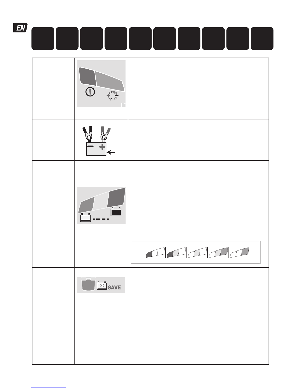
Protection
BMS reset
2
1
Charger will not proceed without user interaction.
LED #2 REVERSE POLARITY: Lights when the battery connections
are incorrect. The charger is electronically protected so no damage will
result, and the output will remain disabled until the connections are
corrected.
BMS RESET: for batteries with a battery management system (BMS) that
protects against deep discharge. Disconnect the charger from mains supply.
Wait for LED #1a/1b to go out. Reconnect to mains supply. A special BMS
reset pulse is delivered for up to 5 seconds. The program should continue to
STEP 4.
STEP 1
Low Volt Start
≥ 0.5V
V
Battery voltage check - OptiMate Lithium automatically activates
if connected battery voltage is at least 0.5 Volt.
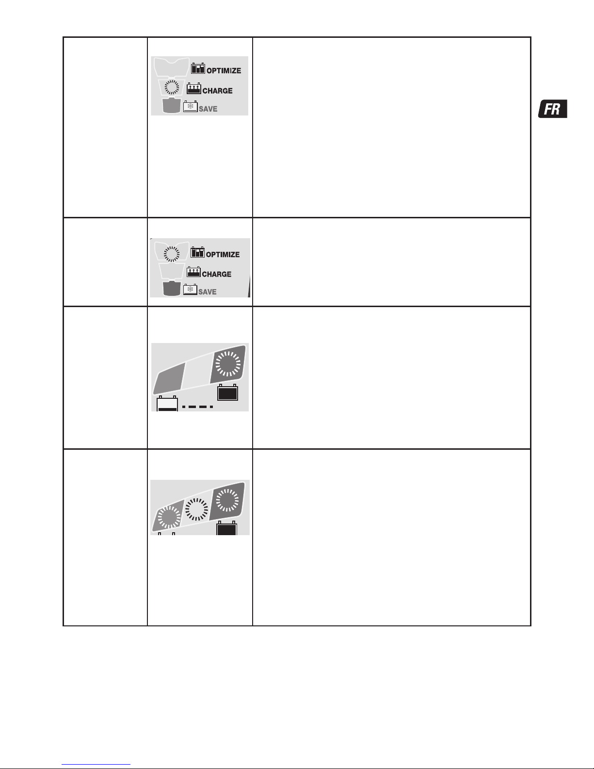
STEP 2
TEST before
charge
STEP 3
Temperature
check
TEST LEDs
6 : GREEN
7 : YELLOW
8 : RED
TEST
8
7
6
TEST LEDs #6/7/8 indicate the battery condition prior to charging. Consult the
table on page 2 to match TEST LED indication to an estimated state of
charge percentage (SOC%).
During the test:
OPTIMIZE minimum charge time is set according to the test result, varying
between 10 minutes for a battery with 80% or higher state of charge to 120
minutes
for a battery with 40% or less state of charge.
Ambient temperature is measured to determine charge voltage parameters.
LOW TEMPERATURE WARNING - LED #8 (red) flashing: The temperature
measured at OptiMate Lithium is below -20 degrees Celcius or 4 degrees
Fahernheit, below the safe charging AND discharging zone for LiFePO4
batteries.
Charging commences after 10 seconds.
8
7
6
90 100%603010%
13.3V 13.6V+ 13.13V13.00V12.80VV
8
7
7
6
0
0.5V
STEP 4
ULTRA LOW
VOLT SAVE
STEP 5
LOW VOLT SAVE
STEP 6
TEST - cell
damage
LED #3 : RED
3
IMPORTANT: If this mode engages read the section VERY FLAT
NEGLECTED BATTERIES on the preceding page.
This mode engages
if the battery was more than 90% discharged / voltage
is below 12.8V safeTº: Charge current is automatically adjusted according
to voltage and ambient temperature measured during the test.
VERY LOW VOLTAGE SAVE for batteries between 0.6V and 8.8V :
Current starts at 125mA and will increase to 325mA depending on charge
progress. If the voltage did not rise above 8.8V within 2 hours, charging will
be suspended and the TEST LED #8 (red) will flash, indicating the battery
may have suffered permanent damage or a professional assessment is
required.
LOW VOLTAGE SAVE for batteries between 8.9V and 12.8V (16V):
Maximum current is set to 1.25A. The battery's charge acceptance is
monitored for unusual behaviour.
A healthy LiFePO
4
battery will progress to CHARGE mode within 4 hours,
otherwise charging will be suspended and TEST LED #8 (red) will flash,
indicating the battery may have suffered permanent damage or a
professional assessment is required.
10
OptiMate
maintenance
9
TEST after
CHARGE
1
Low Volt
Start (0.5V)
2
TEST before
charge
3
Temperature
check
4
Ultra LOW
VOLT SAVE
5
LOW VOLT
SAVE /
cellmonitoring
6
TEST -
cell damage
7
Cell-balancing
CHARGE
8
OPTIMIZE
Page 7
7
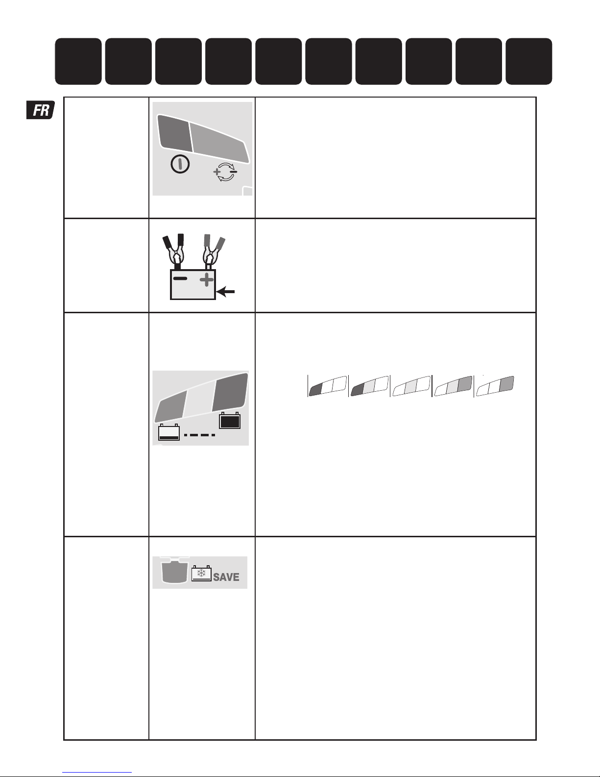
STEP 7
CHARGE
LED #4 : YELLOW
4
The safeTº program limits charge current if the temperature measured
at the OptiMate Lithium is below 0ºC / 32ºF or above 45ºC / 113ºF. If the
temperature was initially below 0ºC / 32ºF charge current is limited to
325mA only for the first hour after which the battery is expected to have
increased it's internal temperature within the normal temperature zone.
Within the normal temperature zone the ampmatic™ LiFePO
4
specific
program automatically determines the most efficient rate of charge
current for the connected battery, according to its state of charge, state of
health, and electrical storage (Ah) capacity. The delivered current may be
anywhere from 1.25A to 5A.
For batteries with an electrical storage (Ah) capacity less than 5Ah charge
current is automatically adjusted lower to an average equal to battery Ah
capacity, e.g. a 2.5Ah / 2500mAh battery receive an average of 2.5 Amps.
NOTE: For safety reasons there is an overall charge time limit of 24 hours
for SAVE and CHARGE modes.
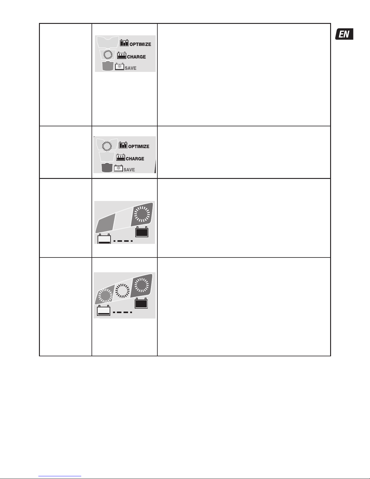
STEP 8
OPTIMIZE
LED #5 : YELLOW
5
The OPTIMIZE mode starts when the voltage has reached 14.4V for the first
time during bulk CHARGE mode.
The ampmatic™ current control program now delivers pulses of current
to equalise the individual cells within the battery and optimizes charge level.
Charging should complete within the minimum charge time set during STEP
3, but if the battery requires further charging the program will extend
OPTIMIZE mode up to a maximum of 2 hours.
STEP 9
TEST after
charge
LED #6 FLASHING
TEST
6
TEST after charge : Delivery of current to the battery is interrupted for
30 minutes* to allow the program to determine the battery’s ability
to retain charge.
* IF charging started in SAVE mode (LED #3, indicating a deep discharged
battery) or the the voltage retention test is extended to 12 hours to confirm
battery health.
The TEST result (indicated on LED # 6, 7, 8) is adjusted in real time according
to the measured battery voltage. Consult the “EARLY WARNING OF BATTERY
PROBLEMS” table on page 2 to match TEST LED indication to an estimated
state of charge percentage (SOC%).
More information is provided in the section “NOTES ON TEST RESULTS”.
STEP 10
OptiMATE
smart
MAINTAIN
LED #6 / 7 / 8 ON
TEST
8
7
6
For batteries with a good
state of health LED #6
(green) will remain on.
MAINTENANCE CHARGE: LED #6 / 7 / 8 steady on
according to final voltage measured at termination of STEP 7.
The MAINTENANCE CHARGE CYCLE consists of 30 minute charge periods
followed by and alternating with a 30 minute ‘rest’ periods, during which
there is no charge current.
During the 30 minute charge cycles current is delivered only if the battery
has lost charge.
The BATTERY REFRESH CYCLE is performed if the charger detects the
battery has lost significant charge. The program returns to OPTIMIZE mode
(LED #5) and then proceeds to the voltage retention test and maintenance
charge cycle.
Read section MAINTAINING A LITHIUM BATTERY FOR EXTENDED PERIODS.
NOTES ON TEST RESULTS:
1. For any test result other than green #6, disconnect the battery from the electrical system it supports, and reconnect the OptiMate. If a
better test result is now obtained, this suggests that the power losses are partly due to an electrical problem in the electrical system and
not in the battery itself.
2.
If the red LED #8 alone, or the yellow #7 and red LED #8 indicate together (or yellow LED alone for a sealed battery), a significant
problem exists. The red / yellow+red LEDs mean that after being charged the battery’s voltage is not being sustained or that despite
recovery attempts the battery was irrecoverable. This may be due to a defect in the battery itself, such as a short-circuited cell, or, in
the case of a battery still connected to the electrical system it supports, it may be signalling a loss of current through deteriorated wiring
or a degraded switch or contact, or in-circuit current-consuming accessories.
A sudden load being switched on while the charger is connected can also cause the battery voltage to dip significantly.
3.
TEST LED #8 (red) flashing - Charging is suspended. During the voltage retention test the voltage reduced below 12.8V within the first
30 minutes, indicating the battery may have suffered permanent damage and a professional assessment is required.
More information
on OptiMate TEST or MONITOR products can be found at www.optimate1.com.
Page 8

8
MAINTAINING A LITHIUM BATTERY FOR EXTENDED PERIODS: A LiFePO
4
battery can be left connected to the OptiMate
Lithium for any extended period of time. The OptiMate Lithium maintenance program is fully automatic, it continuously monitors the
battery voltage and delivers current only if it sensed the battery has lost charge (possibly through connected vehicle or other circuitry
or self discharge). The OptiMate Lithium's maintenance program guarantees the battery will remain at or close to full charge, but
never overcharged.
ECO POWER SAVING MODE WHEN THE CHARGER IS CONNECTED TO AC SUPPLY:
The power converter switches to ECO mode when the charger is not connected to a battery resulting in a very low power draw of less
than 0.5W, equivalent to power consumption of 0.012 kWh per day. When a battery is connected to the charger power consumption
depends on the current demand of the battery and its connected vehicle / electronic circuitry. After the battery has been charged and
the charger is in long term maintenance charge mode (to keep the battery at 100% charge) the total power consumption is estimated to
be 0.024kWh or less per day.
LIMITED WARRANTY
TecMate (International) SA, B-3300 Tienen, Belgium, offers this limited warranty to the original purchaser at retail of this
product. This limited warranty is not transferable. TecMate (International) warrants this battery charger for three years from
date of purchase at retail against defective material or workmanship. If such should occur the unit will be repaired or replaced
at the option of the manufacturer. It is the obligation of the purchaser to forward the unit together with proof of purchase (see
NOTE), transportation or mailing costs prepaid, to the manufacturer or its authorized representative. This limited warranty is
void if the product is misused, subjected to careless handling, or repaired by anyone other than the factory or its authorized
representative. The manufacturer makes no warranty other than this limited warranty and expressly excludes any implied
warranty including any warranty for consequential damages.
THIS IS THE ONLY EXPRESS LIMITED WARRANTY AND THE MANUFACTURER NEITHER ASSUMES NOR AUTHORIZES ANYONE TO
ASSUME OR MAKE ANY OTHER OBLIGATION TOWARDS THE PRODUCT OTHER THAN THIS EXPRESS LIMITED WARRANTY. YOUR
STATUTORY RIGHTS ARE NOT AFFECTED.
NOTE: Details at www.tecmate.com/warranty.
WARRANTY in Canada, USA, Central America and South America:
TecMate North America, Oakville, ON, Canada, as a wholy owned subsidiary of TecMate International, assumes the
responsibility for product warranty in these regions.
More information on TecMate products can be found at www.tecmate.com.
Page 9

9
INSTRUCTIONS IMPORTANTES CONCERNANT LA SÉCURITÉ
CONSERVER CES INSTRUCTIONS. CE MANUEL CONTIENT DES INSTRUCTIONS
IMPORTANTES CONCERNANT LA SÉCURITÉ ET LE FONCTIONNEMENT DU
CHARGEUR OPTIMATE 7 12.8V LIFEPO
4
.
CHARGEUR AUTOMATIQUE POUR BATTERIES 12.8V LIFEPO
4
NE CONVIENT PAS POUR LES BATTERIES NiCd, NiMH, Plomb-Acide OU NON
RECHARGEABLES.
AVERTISSEMENT :
N’utiliser l’appareil qu’à l’intérieur. Ne pas exposer à la pluie ou à la neige. Appareil de Classe II.
a) CONSERVER CES INSTRUCTIONS. CE MANUEL CONTIENT DES INSTRUCTIONS IMPORTANTES CONCERNANT LA SÉCURITÉ
ET LE FONCTIONNEMENT.
b) IL EST DANGEREUX DE TRAVAILLER A PROXIMITÉ D’UNE BATTERIE AU PLOMB. LES BATTERIES PRODUISENT DES GAZ
EXPLOSIFS EN SERVICE NORMAL. IL EST AUSSI IMPORTANT DE TOUJOURS RELIRE LES INSTRUCTIONS AVANT D’UTILISER
LE CHARGEUR ET DE LES SUIVRE À LA LETTRE.
c) POUR RÉDUIRE LE RISQUE D’EXPLOSION, LIRE CES INSTRUCTIONS ET CELLES QUI FIGURENT SUR LA BATTERIE.
d) NE JAMAIS FUMER PRÈS DE LA BATTERIE OU DU MOTEUR ET ÉVITER TOUTE ÉTINCELLE OU FLAMME NUE À PROXIMITÉ DE
CES DERNIERS.
e) UTILISER LE CHARGEUR POUR CHARGER UNE BATTERIE AU PLOMB UNIQUEMENT. CE CHARGEUR N’EST PAS CONÇU POUR
ALIMENTER UN RÉSEAU ÉLECTRIQUE TRÈS BASSE TENSION NI POUR CHARGER DES PILES SÈCHES. LE FAIT D’UTILISER LE
CHARGEUR POUR CHARGER DES PILES SÈCHES POURRAIT ENTRAÎNER L’ÉCLATEMENT DES PILES ET CAUSER DES
BLESSURES OU DES DOMMAGES.
f) NE JAMAIS CHARGER UNE BATTERIE GELÉE.
g) S’IL EST NÉCESSAIRE DE RETIRER LA BATTERIE DU VÉHICULE POUR LA CHARGER, TOUJOURS DÉBRANCHER LA BORNE DE
MISE À LA MASSE EN PREMIER. S’ASSURER QUE LE COURANT AUX ACCESSOIRES DU VÉHICULE EST COUPÉ AFIN D’ÉVITER
LA FORMATION D’UN ARC.
h) PRENDRE CONNAISSANCE DES MESURES DE PRÉCAUTION SPÉCIFIÉES PAR LE FABRICANT DE LA BATTERIE, P. EX.,
VÉRIFIER S‘IL FAUT ENLEVER LES BOUCHONS DES CELLULES LORS DU CHARGEMENT DE LA BATTERIE, ET LES TAUX DE
CHARGEMENT RECOMMANDÉS.
i) SI LE CHARGEUR COMPORTE UN SÉLECTEUR DE TENSION DE SORTIE, CONSULTER LE MANUEL DE L’USAGER DE LA
VOITURE POUR DÉTERMINER LA TENSION DE LA BATTERIE ET POUR S’ASSURER QUE LA TENSION DE SORTIE EST
APPROPRIÉE. SI LE CHARGEUR N’EST PAS MUNI D’UN SÉLECTEUR, NE PAS UTILISER LE CHARGEUR À MOINS QUE LA
TENSION DE LA BATTERIE NE SOIT IDENTIQUE À LA TENSION DE SORTIE NOMINALE DU CHARGEUR.
j) NE JAMAIS PLACER LE CHARGEUR DIRECTEMENT SOUS LA BATTERIE À CHARGER OU AU-DESSUS DE CETTE DERNIÈRE.
LES GAZ OU LES FLUIDES QUI S’ÉCHAPPENT DE LA BATTERIE PEUVENT ENTRAÎNER LA CORROSION DU CHARGEUR OU
L’ENDOMMAGER. PLACER LE CHARGEUR AUSSI LOIN DE LA BATTERIE QUE LES CABLES C.C. LE PERMETTENT.
k) NE PAS FAIRE FONCTIONNER LE CHARGEUR DANS UN ESPACE CLOS ET/OU NE PAS GÊNER LA VENTILATION.
l) METTRE LES INTERRUPTEURS DU CHARGEUR HORS CIRCUIT ET RETIRER LE CORDON C.A. DE LA PRISE AVANT DE METTRE
ET D’ENLEVER LES PINCES DU CORDON C.C. S’ASSURER QUE LES PINCES NE SE TOUCHENT PAS.
m) SUIVRE LES ÉTAPES SUIVANTES LORSQUE LA BATTERIE SE TROUVE DANS LE VÉHICULE.
UNE ÉTINCELLE PRÈS DE LA BATTERIE POURRAIT PROVOQUER L’EXPLOSION DE CETTE DERNIÈRE. POUR RÉDUIRE LE
RISQUE D’ÉTINCELLE À PROXIMITÉ DE LA BATTERIE :
(i) PLACER LES CORDONS C.A. ET C.C. DE MANIÈRE À ÉVITER QU’ILS SOIENT ENDOMMAGÉS PAR LE CAPOT, UNE PORTIÈRE
OU LES PIÈCES EN MOUVEMENT DU MOTEUR ;
(ii) FAIRE ATTENTION AUX PALES, AUX COURROIES ET AUX POULIES DU VENTILATEUR AINSI QU’À TOUTE AUTRE PIÈCE
SUSCEPTIBLE DE CAUSER DES BLESSURES ;
(iii) VÉRIFIER LA POLARITÉ DES BORNES DE LA BATTERIE. LE DIAMÈTRE DE LA BORNE POSITIVE
(POS, P, +) EST GÉNÉRALEMENT SUPÉRIEUR À CELUI DE LA BORNE NÉGATIVE (NÉG, N, –) ;
(iv) DÉTERMINER QUELLE BORNE EST MISE À LA MASSE (RACCORDÉE AU CHÂSSIS). SI LA BORNE
SÉCURITÉ US & CAN
Page 10

10
NÉGATIVE EST RACCORDÉE AU CHÂSSIS (COMME DANS LA PLUPART DES CAS), VOIR LE POINT (v).
SI LA BORNE POSITIVE EST RACCORDÉE AU CHÂSSIS, VOIR LE POINT (vi) ;
(v) SI LA BORNE NÉGATIVE EST MISE À LA MASSE, RACCORDER LA PINCE POSITIVE (ROUGE) DU
CHARGEUR À LA BORNE POSITIVE (POS, P, +) NON MISE À LA MASSE DE LA BATTERIE. RACCORDER LA
PINCE NÉGATIVE (NOIRE) AU CHÂSSIS DU VÉHICULE OU AU MOTEUR, LOIN DE LA BATTERIE. NE PAS
RACCORDER LA PINCE AU CARBURATEUR, AUX CANALISATIONS D’ESSENCE NI AUX PIÈCES DE LA
CARROSSERIE EN TÔLE. RACCORDER À UNE PIÈCE DU CADRE OU DU MOTEUR EN TÔLE DE FORTE
ÉPAISSEUR ;
(vi) SI LA BORNE POSITIVE EST MISE À LA MASSE, RACCORDER LA PINCE NÉGATIVE (NOIRE) DU
CHARGEUR À LA BORNE NÉGATIVE (NÉG, N, –) NON MISE À LA MASSE DE LA BATTERIE. RACCORDER
LA PINCE POSITIVE (ROUGE) AU CHÂSSIS DU VÉHICULE OU AU MOTEUR, LOIN DE LA BATTERIE. NE
PAS RACCORDER LA PINCE AU CARBURATEUR, AUX CANALISATIONS D’ESSENCE NI AUX PIÈCES DE LA
CARROSSERIE EN TÔLE. RACCORDER À UNE PIÈCE DU CADRE OU DU MOTEUR EN TÔLE DE FORTE
ÉPAISSEUR ;
(vii) BRANCHER LE CORDON D’ALIMENTATION C.A. DU CHARGEUR ;
(viii) POUR INTERROMPRE L’ALIMENTATION DU CHARGEUR, METTRE LES INTERRUPTEURS HORS
CIRCUIT, RETIRER LE CORDON C.A. DE LA PRISE, ENLEVER LA PINCE RACCORDÉE AU CHÂSSIS ET EN
DERNIER LIEU CELLE RACCORDÉE À LA BATTERIE.
n) SUIVRE LES ÉTAPES SUIVANTES LORSQUE LA BATTERIE EST À L’EXTÉRIEUR DU VÉHICULE.
UNE ÉTINCELLE PRÈS DE LA BATTERIE POURRAIT PROVOQUER L’EXPLOSION DE CETTE DERNIÈRE. POUR RÉDUIRE LE
RISQUE D’ÉTINCELLE À PROXIMITÉ DE LA BATTERIE :
(i) VÉRIFIER LA POLARITÉ DES BORNES DE LA BATTERIE. LE DIAMÈTRE DE LA BORNE POSITIVE
(POS, P, +) EST GÉNÉRALEMENT SUPÉRIEUR À CELUI DE LA BORNE NÉGATIVE (NÉG, N, –) ;
(ii) RACCORDER UN CÂBLE DE BATTERIE ISOLÉ No 6 AWG MESURANT AU MOINS 60 CM DE
LONGUEUR À LA BORNE NÉGATIVE (NÉG, N, –) ;
(iii) RACCORDER LA PINCE POSITIVE (ROUGE) À LA BORNE POSITIVE (POS, P, +) DE LA BATTERIE ;
(iv) SE PLACER ET TENIR L’EXTRÉMITÉ LIBRE DU CÂBLE AUSSI LOIN QUE POSSIBLE DE LA BATTERIE,
PUIS RACCORDER LA PINCE NÉGATIVE (NOIRE) DU CHARGEUR À L’EXTRÉMITÉ LIBRE DU CÂBLE ;
(v) NE PAS SE PLACER FACE À LA BATTERIE POUR EFFECTUER LE DERNIER RACCORDEMENT ;
(vi) RACCORDER LE CORDON D’ALIMENTATION C.A. DU CHARGEUR À LA PRISE ;
(vii) POUR INTERROMPRE L’ALIMENTATION DU CHARGEUR, METTRE LES INTERRUPTEURS HORS
CIRCUIT, RETIRER LE CORDON C.A. DE LA PRISE, ENLEVER LA PINCE RACCORDÉE AU CHÂSSIS ET EN
DERNIER LIEU CELLE RACCORDÉE À LA BATTERIE. SE PLACER AUSSI LOIN QUE POSSIBLE DE LA BATTERIE
POUR DÉFAIRE LA PREMIÈRE CONNEXION.
SÉCURITÉ US & CAN
Page 11

11
CHARGEUR AUTOMATIQUE AVEC DIAGNOSTIC POUR BATTERIES 12.8 V à100Ah :
IMPORTANT :
LIRE ENTIÈREMENT LES INSTRUCTIONS SUIVANTES AVANT D’UTILISER LE CHARGEUR
Cet appareil n’est pas destiné à être utilisé par des personnes (y compris des enfants) possédant des
capacités physiques, sensorielles ou mentales réduites, ou manquant d'expérience et de connaissance,
sauf si elles bénéficient d’une surveillance ou ont reçu des instructions concernant l’utilisation de
l’appareil d’une personne responsable de leur sécurité. Les enfants doivent faire l’objet d’une surveillance
pour s’assurer qu’ils ne jouent pas avec l’appareil.
AVERTISSEMENT DE SÉCURITÉ et REMARQUES
: Les batteries émettent des GAZ EXPLOSIFS - il faut interdire les
flammes ou les étincelles à proximité
.
Avant d’établir ou de rompre les connexions de courant continu à la batterie, déconnecter l’alimentation secteur. L’acide des
batteries est un puissant corrosif. Porter des vêtements et lunettes protecteurs et éviter tout contact. En cas de contact accidentel,
laver immédiatement à l’eau et au savon. S’assurer que les bornes des batteries ne sont pas branlantes ; le cas échéant la batterie
doit subir une évaluation professionnelle. Si les bornes sont corrodées, nettoyer à l’aide d’une brosse de cuivre ; si elles sont
grasses ou sales, nettoyer à l’aide d’un torchon trempé dans du détergent. Utiliser uniquement le chargeur si les câbles et
connecteurs d’entrée et de sortie sont en bon état et non endommagés. Si le câble d’entrée est endommagé, il est essentiel de le
faire remplacer par le constructeur, son agent de service autorisé ou un atelier qualifié, pour éviter tout danger. Protéger le chargeur
contre les acides et fumées acides, l’humidité et un environnement humide, aussi bien durant l’usage que l’entreposage. Les dégâts
résultant de la corrosion, de l’oxydation ou de courts-circuits internes ne sont pas couverts par la garantie. Durant le chargement,
éloigner le chargeur de la batterie pour éviter la contamination par l’acide ou les vapeurs acides ou l’exposition à ceux-ci. En cas
d’utilisation horizontale, placer le chargeur sur une surface dure et plane, PAS en plastique, tissu ou cuir. Utiliser les trous de fixation
de la base pour fixer le chargeur sur toute surface verticale appropriée et solide.
EXPOSITION AUX LIQUIDES : Ce chargeur est conçu pour résister à l’exposition aux liquides qui tomberaient accidentellement
sur le boîtier, ou à une pluie légère. Une exposition prolongée à des liquides tombants ou à la pluie est à déconseiller. Une durée de
vie supérieure résultera d’une telle précaution. Une panne due à l’oxydation résultant d’une pénétration de liquide dans les
composants électroniques,bloc connecteurs ou fiches,ne sera pas couverte par la garantie.
BRANCHEMENT DU CHARGEUR A LA BATTERIE
1.
Débranchez l’alimentation secteur avant d’effectuer un branchement CC/batterie ou de le débrancher.
2. Si vous chargez une batterie installée dans le véhicule avec les pinces pour batterie, avant les branchements, vérifiez d’abord
que les pinces pour batterie peuvent être positionnées en toute sécurité loin du câblage voisin, d’un tube métallique ou du
châssis.
Respectez l’ordre qui suit : branchez d’abord la borne de la batterie non raccordée au
châssis (normalement positive) puis, branchez l’autre pince pour batterie (normalement
négative) au châssis à un endroit bien éloigné de la batterie et du conduit de carburant.
Débranchez toujours dans l’ordre inverse.
3. Lorsque vous chargez une batterie hors du véhicule avec les pinces pour batterie, placez-la dans un endroit bien ventilé.
Branchez le chargeur à la batterie : La pince ROUGE sur la borne POSITIVE (POS, P ou +) et la pince NOIRE sur la borne
NÉGATIVE (NEG, N ou –). Vérifiez que les branchements sont bien fixés. Un bon contact est important.
COMMENCER LA CHARGE
TEMPS DE CHARGE
Le temps de charge dépend de la température ambiante. Le programme safeTº limite le courant de charge si la température
mesurée sur l'OptiMate Lithium est inférieure à 0ºC (32ºF) ou supérieure à 45ºC (113ºF). Si elle se situe dans la plage normale, le
programme spécifique LiFePO4 ampmatic™ détermine automatiquement le courant de charge le plus efficace pour la batterie
connectée en fonction de son état de charge, de son état de fonctionnement et de sa capacité de stockage électrique (Ah). Le
courant délivré est situé entre 1,25A et 5A.
Temps de charge pour une batterie déchargée mais en parfait état:
Pour les batteries d'une tension nominale comprise entre 2,5Ah et 5Ah : de 60 à 120 minutes pour effectuer le test de
rétention de voltage.
Pour les batteries d'une tension nominale supérieure à 5Ah : un peu moins de 25% de la tension de la batterie; il faut donc au
maximum environ 5 heures à une batterie de 50Ah pour effectuer le test de rétention de voltage.
Des batteries complètement déchargées peuvent nécessiter beaucoup plus de temps.
Page 12
12
Protection
RÉINITIALISATION DU
BMS
2
1
la charge ne s’effectue pas sans l’intervention de l’utilisateur.
LED N°2 POLARITÉ INVERSE: s’allume lorsque les connexions de la batterie
sont incorrects. Le chargeur est protégé électroniquement, donc ne peut subir
aucun dommage, et la sortie restera désactivée jusqu'à ce que les
connexions soient bonnes.
RÉINITIALISATION DU BMS : pour les batteries avec système de gestion de
batterie (BMS) qui empêche la décharge profonde. Déconnectez le chargeur
de l’alimentation secteur. Attendez que la LED #1a/1b s’éteigne.
Reconnectez-le à l’alimentation secteur. Une impulsion spéciale de
réinitialisation du BMS est fournie pendant maximum 5 secondes. Le
programme passe à l’ÉTAPE 4.
ÉTAPE1
Démarrage à
basse tension
(Bat ≥ 0,5 V)
V
Vérification de la tension de la batterie – OptiMate Lithium
s’active si la tension de la batterie connectée est d’au moins 0,5
V.
ÉTAPE 2
TEST avant la
charge
ÉTAPE 3
LED TEST
Nº6: VERTE
Nº7: JAUNE
Nº8: ROUGE
TEST
8
7
6
LES LED TEST #6/7/8 indiquent l’état de la batterie avant le début de la
charge. Reportez-vous au tableau page 2 pour obtenir les indications des LED
TEST qui correspondent à un pourcentage de l'état de charge estimé (% de
l’état de charge, SOC).
8
7
6
90 100%603010%
13.3V 13.6V+ 13.13V13.00V12.80VV
8
7
7
6
0
0.5V
Pendant le test: OPTIMISATION le temps de charge minimum est défini en
fonction des résultats du test, variant entre 10minutes, pour une batterie
chargée à 80% ou plus, et 120minutes pour une batterie chargée à 40% ou
moins.
La température ambiante est mesurée pour déterminer les paramètres de
tension de la charge. La charge commence après 10 secondes.
AVERTISSEMENT DE TEMPÉRATURE BASSE - LED #8 (rouge) clignotante:
la température mesurée sur l'OptiMate Lithium est inférieure à -20°C
(-4°F), et donc inférieure à la limite de sécurité de charge ET de décharge
pour les batteries LiFePO
4
.
ÉTAPE 4
Récuperation ultra
bassse tension
ÉTAPE 5
Récupération
faible VOLTAGE
ÉTAPE 6
TEST défaut des
cellules
LED #3 : ROUGE
3
IMPORTANT : si ce mode se déclenche, lisez la section BATTERIES NON
ENTRETENUES TRÈS FAIBLES à la page précédente.
Ce mode se déclenche si la batterie était déchargée à plus de 90 % ou si la
tension est inférieure à 12.8 V. safe T° : le courant de charge est
automatiquement ajusté en fonction de la tension et de la température
ambiante mesurée lors du test.
RÉCUPÉRATION À TRÈS BASSE TENSION pour des batteries entre 0.6 V
(0.75V) et 8.8 V: le courant commence à 125 mA et augmente jusqu’à 325
mA, en fonction de l’évolution de la charge. Si la tension n’a pas dépassé 8.8
V après 2 heures, la charge s’interrompt et la LED TEST #8 (rouge) clignote
pour indiquer qu’il est possible que la batterie ait subi des dommages
irréversibles ou que l’expertise d'un professionnel est nécessaire.
RÉCUPÉRATION À BASSE TENSION pour des batteries entre 8.9 V et 12.8V:
le courant maximal est fixé à 1.25 A. L’acceptation de charge de la batterie
est surveillée dans l’éventualité d’un comportement inhabituel. Une batterie
LiFePO
4
en bon état passe en mode CHARGE en moins de 4 heures ; dans le
cas contraire, la charge s’interrompt et la LED TEST #8 (rouge) clignote pour
indiquer qu’il est possible que la batterie ait subi des dommages irréversibles
ou que l’expertise d'un professionnel est nécessaire.
1091 2
3 4 5 6 7 8
Entretien
OptiMate ‘365’
TEST
(après la charge)
Démarrage
basse tension
(0.5V)
TEST (avant
la charge)
Contrôle de
température
RÉCUPÉRATION
ultra basse
tension
TEST
défaut des cellules
CHARGE avec
équilibrage
des cellules
OPTIMISATION
RÉCUPÉRATION
FAIBLE VOLTAGE /
contrôle des cellules
Page 13
13
ÉTAPE 7
CHARGE
LED #4 : JAUNE
4
Le programme safe Tº limite le courant de charge si la température
mesurée sur l’OptiMate Lithium est inférieure à 0°C (32°F) ou supérieure à
45°C (113°F). Si la température était au départ inférieure à 0 °C (32 °F), le
courant de charge est limité à 325 mA uniquement pour la première heure,
ensuite la température interne de la batterie est supposée se situer dans la
plage de température normale.
Dans la plage de température normale, le programme spécifique LiFePO
4
ampmatic™ détermine automatiquement le courant de charge le plus
efficace pour la batterie connectée en fonction de son état de charge, de son
état de fonctionnement et de sa capacité de stockage électrique (Ah). Le
courant délivré est situé entre 1.25 A et 9.5 A.
Pour les batteries avec une capacité de stockage électrique (Ah) inférieure à
10 Ah (8Ah), le courant de charge est automatiquement ajusté à une valeur
inférieure à une moyenne égale à la capacité Ah de la batterie : une batterie
de 2.5 Ah/2 500 mAh reçoit ainsi par exemple une moyenne de 2.5 A.
REMARQUE : pour des raisons de sécurité, il y a une limite de charge absolue
de 24 heures pour les modes RÉCUPÉRATION et CHARGE.
ÉTAPE 8
OPTIMISATION
LED #5 : JAUNE
5
Le mode OPTIMISATION débute quand la tension a atteint 14.4V pour la
première fois au cours du mode CHARGE PRINCIPALE.
Le programme de contrôle du courant ampmatic™ envoie maintenant
des impulsions de courant afin d’égaliser les cellules individuelles au sein de
la batterie et d’optimiser le niveau de charge.
La charge ne devrait prendre que le temps de charge minimum indiqué lors
de l’ÉTAPE3, mais si la batterie nécessite une charge supplémentaire, le
programme étendra le mode OPTIMISATION jusqu'à maximum 2heures.
ÉTAPE 9
après
la charge
LED #6 CLIGNOTANTE
TEST
6
TEST après la charge: L’arrivée du courant dans la batterie est interrompue
pendant 30 minutes* pour permettre au programme de déterminer la
capacité de la batterie à retenir la charge.
* SI la charge a démarré en mode RÉCUPÉRATION (LED #3 indiquant une
batterie complètement déchargée), le test de rétention de tension est étendu
à 12 heures en vue de confirmer l’état de la batterie.
Le résultat du TEST (indiqué par la LED #6, 7, 8) est ajusté en temps réel en
fonction de la tension mesurée sur la batterie. Reportez-vous au tableau
« AVERTISSEMENTS ANTICIPÉS DES PROBLÈMES DE BATTERIE » à la page 2
pour obtenir les indications des LED TEST qui correspondent à un
pourcentage de l'état de charge estimé (% de l’état de charge, SOC).
Pour de plus amples informations, reportez-vous à la section « NOTES
CONCERNANT LES RÉSULTATS DES TESTS ».
ÉTAPE 10
ENTRETIEN
OptiMATE
intelligent
LED #6 / 7 / 8
ALLUMÉES
8
7
6
Pour des batteries en bon état, la
LED nº6 (verte) reste allumée.
CHARGE DE MAINTENANCE : LED #6/7/8 fixes en fonction de la tension
finale mesurée à la fin de l’ÉTAPE 7.
Le CYCLE DE CHARGE DE MAINTENANCE est composé de périodes de charge
de
30 minutes en alternance avec des périodes de « repos » de 30 minutes
pendant lesquelles il n’y a pas de courant de charge.
Pendant les cycles de charge de 30 minutes, du courant sera fourni
uniquement si la batterie s'est déchargée.
Le CYCLE DE RAFRAÎCHISSEMENT DE LA BATTERIE est effectué si le chargeur
détecte que la batterie a perdu une charge importante. Le programme
retourne en mode OPTIMIZE (LED #5) puis effectue le test de rétention de
tension et le cycle de charge de maintenance.
Consultez la section MAINTENANCE D'UNE BATTERIE AU LITHIUM POUR DES
PÉRIODES PROLONGÉES.
REMARQUES SUR LES RÉSULTATS DU TEST:
1. Pour tout résultat différent d’une LED #6 verte, déconnecter la batterie du système électrique du véhivcule et reconnecter l’OptiMate.
Si on obtient ensuite un meilleur résultat, cela indique que les pertes de puissance sont dues en partie à un problème du système
électrique et non à la batterie. Si les mauvais résultats persistent, il est conseillé d’amener la batterie dans un atelier professionnel
équipé d’appareils de test professionnels pour procéder à une analyse approfondie.
2. Si la LED #8 rouge seule, ou la LED #7 jaune et la LED #8 rouge s’allument en même temps, un problème signifi catif existe. Les
rouge (ou LED jaune + rouge seul pour batterie scellée) signifie qu’après la charge la tension de la batterie n’est pas maintenue ou que
malgré des tentatives de récupération, la batterie est irrécupérable. Ceci peut être dû à une panne de la batterie comme une cellule
Page 14

1414
court-circuitée ou une sulfatation totale, ou, dans le cas d’une batterie toujours connectée au système électrique supporté, le LED #8
rouge peut signaler la perte de courant via un câblage détérioré ou un commutateur ou un contact dégradé, ou la présence
d’accessoires consommateurs de courant au sein du circuit. Une consommation soudaine, comme l’allumage des phares du véhicule
lorsque le chargeur est connecté, peut également entraîner une chute de tension significative sur la batterie.
3. Ce test de rétention de voltage est un résultat signifi cativement probant mais pas nécessairement concluant de la condition de la
batterie, qui pour une batterie à cycles profonds peut être établie plus précisément à l’aide d’un testeur de charge de précision TestMate
12V Deep Cycle.
MAINTENANCE D’UNE BATTERIE DURANT DES PÉRIODES PROLONGÉES: L'OptiMate maintiendra une batterie dont
l'état est bon, en toute sécurité durant plusieurs mois. Vérifier au moins une fois par quinzaine la sécurité des connexions entre
chargeur et batterie. Dans le cas de batteries équipées de bouchons de remplissage sur chaque cellule, déconnecter la batterie du
chargeur, vérifier le niveau d’électrolyte et faire l’appoint si nécessaire (en eau distillée, PAS en acide), puis reconnecter. Lors de
la manipulation de batteries ou à proximité de celles-ci, toujours respecter les AVERTISSEMENTS DE SÉCURITÉ ci-dessus.
MODE ÉCONOMIE D’ÉNERGIE LORSQUE LE CHARGEUR EST CONNECTÉ A L’ALIMENTATION SECTEUR :
Le convertisseur d'énergie se désactive et passe en mode ECO lorsque le chargeur est déconnecté de la batterie, la puissance
demandée diminue jusque 0.5W, l'équivalent d'une consommation d'énergie de 0,012 kWh par jour. Lorsqu'une batterie est
branchée au chargeur, la consommation d'énergie dépend de la demande en courant de la batterie et du véhicule/des circuits
électroniques raccordés. Une fois que la batterie est chargée et que le programme de charge est en mode de charge d'entretien à
long terme (pour garder la batterie chargée à 100 %), la consommation d'énergie totale est estimée à 0,024 kWh ou moins par jour.
GARANTIE LIMITÉE
TecMate International SA, B-3300 Tienen, Belgique, consent la présente garantie au premier client utilisateur de ce produit,
sans possibilité de transfert. TecMate (International) garantit ce chargeur pendant trois ans à compter de la date d’achat au
détail contre les défauts de composants ou d’assemblage. Le cas échéant, le chargeur sera réparé ou remplacé à la discrétion
du fabricant. L’acheteur doit expédier, à ses frais, l’appareil ainsi qu’une preuve d’achat (voir "NOTE") au fabricant ou à son
représentant agréé. Cette garantie limitée devient nulle si l’appareil est utilisé ou manipulé de façon inadéquate ou s’il a été
réparé par toute personne physique ou morale autre que le fabricant ou un représentant agréé. Le fabricant n’offre aucune
autre garantie que la présente, et exclut expressément toute garantie contre les dommages conséquentiels.
CECI EST LA SEULE GARANTIE EXPRESSÉMENT CONSENTIE PAR LE FABRICANT. CELUI-CI N’ASSUME ET N’AUTORISE
QUICONQUE A ASSUMER OU ETABLIR TOUTE AUTRE OBLIGATION LIÉE À CE PRODUIT, AUTRE QUE CETTE GARANTIE LIMITÉE
EXPRESSÉMENT CONSENTIE. VOS DROITES STATUTAIRES NE SONT PAS AFFECTÉES.
NOTE : Voir www.tecmate.com/warranty ou contactez warranty@tecmate.com
Garantie applicable en Amérique du Nord (Canada et USA), Amérique Centrale et Amérique du Sud
TecMate North America, Oakville, ON, Canada, en tant que filiale de TecMate (International) S.A., assume toute obligation
légale de garantie et service après-vente pour les produits distribués en Amérique du Nord (Canada et USA), Amérique Centrale
et Amérique du Sud.
Vous trouverez plus d'informations sur les produitsTecMate sur www.tecmate.com.
Page 15

15
Cargador con diagnóstico automático para baterías LiFePO4 (FOSFATO
DE LITIO-HIERRO) de 12,8V, baterías de 100Ah:
IMPORTANTE: LEA COMPLETAMENTE LAS SIGUIENTES INSTRUCCIONES ANTES DE UTILIZAR EL
CARGADOR
Este aparato no puede ser utilizado por que lo utilicen personas (incluidos niños) con capacidades físicas,
sensoriales o mentales disminuidas, o bien con falta de experiencia y conocimientos, a menos que una
persona responsable de su seguridad las supervise o les dé instrucciones sobre el uso del aparato. Es
necesario supervisar a los niños para asegurarse de que no juegan con el aparato.
AVISOS Y PRECAUCIONES DE SEGURIDAD:
Las baterías emiten GASES EXPLOSIVOS, evite la posibilidad de llamas o
chispas cerca de las baterías. Desconecte de la red CA antes de realizar o deshacer conexiones en la batería. El ácido de la
batería es altamente corrosivo. Utilice ropa y gafas de protección y evite el contacto con el ácido. En caso de contacto accidental,
enjuague inmediatamente la zona afectada con agua y jabón. Compruebe que los polos de la batería no estén sueltos, y si lo están,
lleve la batería a un servicio técnico. Si los bornes presentan corrosión, límpielos con un cepillo de hilo de cobre, y si presentan
grasa o suciedad, límpielos con un trapo humedecido en detergente. Utilice el cargador solamente si los cables y conectores de
entrada y salida se encuentran en buenas condiciones y sin daños. Si el cable de entrada está dañado, es fundamental que el
fabricante, el servicio técnico autorizado o un taller capacitado lo sustituyan sin demora para evitar riesgos. Proteja el cargador del
ácido y de las emisiones de gases de ácido y de ambientes húmedos o superficies mojadas durante su utilización y
almacenamiento. La garantía no cubre daños derivados de la corrosión, oxidación o cortocircuitos eléctricos internos. Coloque el
cargador a una distancia adecuada de la batería durante la recarga para evitar la contaminación o la exposición al ácido o vapores
de ácido. Si se utiliza en posición horizontal, coloque el cargador en una superficie dura y plana, PERO NUNCA sobre plástico, tela o
piel. Utilice los orificios de fijación de la base de la carcasa para fijar el cargador en una superficie cómoda y totalmente horizontal.
EXPOSICIÓN A LÍQUIDOS: Este cargador fue desarrollado para resistir a líquidos que hubieran sido derramados de form
accidental o a intemperies ligeras. No obstante, no se recomiendan las exposiciones prolongadas, que podrían menguar la duración
de vida del cargador. Los desgastes, resultado de la oxidación debida al ataque eventual de líquidos en los componentes
electrónicos, los conectadores o enchufes no se cubren por la garantía.
CONEXIÓN DEL CARGADOR A LA BATERÍA
1. Desconecte la alimentación CA antes de efectuar o deshacer las conexiones en la batería.
2. Si se va a cargar una batería montada en el vehículo con las pinzas, compruebe primero que las pinzas se pueden colocar de
forma segura y correcta, lejos del cableado, los tubos metálicos o del chasis, antes de efectuar las conexiones. Realice las
conexiones en este orden: realice primero la conexión al terminal de la batería que no está conectado con el chasis
(normalmente positivo), luego conecte la otra pinza de batería (normalmente negativa) al bastidor a una distancia sufi ciente de
la batería y de la tubería de combustible. Desconecte siempre realizando los pasos anteriores en orden inverso.
3. Cuando cargue una batería fuera del vehículo con las pinzas, colóquela en un lugar bien ventilado. Conecte el cargador a la
batería: pinza ROJA con el terminal POSITIVO (POS, P o +) y pinza NEGRA con el terminal NEGATIVO (NEG, N o –). Asegúrese de
que las conexiones son firmes y seguras. Es importante que hagan bien contacto.
INICIAR LE CARGA
TIEMPO DE CARGA : El tiempo de carga se verá afectado por la temperatura ambiente. El programa safeTº limita la corriente
de carga si la temperatura registrada en OptiMate Lithium es inferior a 0ºC (32ºF) o superior a 45ºC (113ºF). Dentro del intervalo
normal de temperatura, el programa específico LiFePO4 ampmatic™ determina de forma automática la tasa más eficaz de
corriente de carga para la batería conectada, en función del estado de carga, su conservación y capacidad de almacenamiento
eléctrico (Ah). La corriente suministrada puede variar entre 1,25A y 5A.
Tiempo de carga de una batería descuidada sin otros daños:
Baterías clasificadas entre 2,5Ah y 5Ah: 60 a 120minutos para llevar a cabo la prueba de retención de tensión.
Baterías con una clasificación superior a 5Ah: ligeramente inferior al 25% de la clasificación Ah de la batería; por lo que una
batería de 50Ah no debería requerir más de 5horas para efectuar la prueba de retención de tensión.
En caso de baterías muy descargadas puede tardar mucho más.
LA SEGURIDAD
Page 16

1616
Protección
REINICIO DEL
BMS
2
1
El cargador no continuará hasta que el usuario actúe.
LED n.º2 POLARIDAD INVERTIDA: se ilumina cuando las conexiones de la
batería son incorrectas. El cargador está protegido electrónicamente, con lo
que no se producirá ningún daño y la salida permanecerá desactivada hasta
que se corrijan las conexiones.
REINICIO DEL BMS: para baterías con un sistema de gestión de baterías
(BMS) que las proteja de la descarga profunda.
Desconecte el cargador del suministro eléctrico. Espere hasta que el LED n.º
1a/1b se apague. Vuelva a conectar el suministro eléctrico. Se producirá un
impulso especial de reinicio del BMS durante un máximo de 5 s. El programa
debería continuar con el PASO 4.
PASO1
Arranque de baja
tensión (Bat. ≥
0,5 V)
V
Comprobación de la tensión de la batería: OptiMate Lithium se
activa si la tensión de la batería conectada es de al menos 0,5
voltios.
PASO 2
PRUEBA antes
de la carga
PASO 3
Comprobaci
ón
de temperatura
LED DE PRUEBA
N.º6: VERDE
N.º7: AMARILLO
N.º8: ROJO
TEST
8
7
6
Los LED DE PRUEBA n.º 6, 7 y 8 indican el estado de la batería antes de
cargarla. Consulte la tabla que figura en la página 2 para asociar la indicación
de los LED DE PRUEBA al estado de porcentaje de carga estimado (SOC%).
8
7
6
90 100%603010%
13.3V 13.6V+ 13.13V13.00V12.80VV
8
7
7
6
0
0.5V
Durante la prueba:
El tiempo de carga mínimo del modo OPTIMIZACIÓN se define según el
resultado de la prueba, y varía entre los 10minutos necesarios para una
batería con una carga del 80% o más y los 120minutos para una batería con
una carga del 40% o inferior. También se mide la temperatura ambiente
para determinar los parámetros de la tensión de carga.
ADVERTENCIA DE TEMPERATURA BAJA: LED #8 (rojo) parpadeando: la
temperatura registrada en OptiMate Lithium es inferior a -20°C (-4°F),
inferior a la carga segura Y a la zona de descarga de las baterías LiFePO4.
La carga comienza tras 10 segundos.
PASO 4
RECUPERACIÓN
en caso de
TENSIÓN
ultrabaja
PASO 5
TENSIÓN baja
RECUPERACIÓN
PASO 6
PRUEBA daño en
las células
LED #3 : ROJO
3
IMPORTANTE: si se activa este modo, consulte el apartado BATERÍAS
DESCUIDADAS MUY DESCARGADAS, en la página anterior.
Si este modo se activa, la batería presentaba una descarga superior al 90% /
tensión inferior a 12,8V. Safe Tº: la corriente de carga se ajusta
automáticamente en función de la tensión y temperatura ambiente
registradas durante la prueba.
RECUPERACIÓN EN CASO DE MUY BAJA TENSIÓN para baterías entre
0,6V (0,75V) y 8,8V: la corriente se inicia a 125 mA y se incrementa hasta
325 mA en función del proceso de carga. Si la tensión no supera los 8,8V en
2horas, la carga se suspenderá y el LED DE PRUEBA n.º8 (rojo) parpadeará
para indicar que la batería puede haber sufrido daños permanentes o que se
requiere una valoración profesional.
RECUPERACIÓN EN CASO DE BAJA TENSIÓN para baterías entre 8,9V y
12,8V: la corriente máxima está fijada a 1,25 A. Se controla la asimilación de
la carga de la batería para detectar algún comportamiento anómalo. Una
batería LiFePO
4
en buen estado pasará al modo CARGA en 4 horas; de lo
contrario, la carga se suspenderá y el LED DE PRUEBA n.º8 (rojo) parpadeará
para indicar que la batería puede haber sufrido daños permanentes o que se
requiere una valoración profesional.
1091 2
3 4 5 6 7 8
Mantenimiento
de
OptiMate ‘365’
PRUEBA tras
la carga
Arranque de
baja tensión
(0.5V)
PRUEBA antes
de la carga
Comprobación
de temperatura
RECUPERACIÓN
en caso
de tensión
ultrabaja
TENSIÓN BAJA
RECUPERACIÓN
/ supervisión
de las células
PRUEBA -
daño en
las células
CARGA de
equilibrio de
células
OPTIMIZACIÓN
Page 17

1717
PASO 7
CARGA
LED #4 : AMARILLO
4
El programa safeTº limita la corriente de carga si OptiMate Lithium registra
una temperatura inferior a 0°C (32°F) o superior a 45°C (113°F). Si la
temperatura inicial es inferior a 0°C (32°F), la corriente de carga se limita a
325mA únicamente durante la primera hora, tras la que se espera que la
temperatura interna de la batería haya aumentado dentro del intervalo
normal.
Dentro del intervalo normal de temperatura, el programa específico de
LiFePO
4
de ampmatic™ determina de forma automática la tasa más
eficaz de corriente de carga para la batería conectada, en función del estado
de carga, su conservación y capacidad de almacenamiento eléctrico (Ah). La
corriente suministrada puede variar entre 1,25A y 9,5A.
En las baterías con una capacidad de almacenamiento eléctrico (Ah) inferior a
10Ah (8Ah), la corriente de carga se ajusta automáticamente a un nivel
inferior equivalente a la media de la capacidad Ah; por ejemplo, una batería
de 2,5Ah (2500mAh) recibiría una media de 2,5A.
NOTA: por razones de seguridad hay un límite temporal de carga general de
24 horas para los modos RECUPERACIÓN y CARGA.
PASO 8
OPTIMIZACIÓN
LED #5 : AMARILLO
5
El modo de OPTIMIZACIÓN empieza cuando la tensión alcanza los 14,4V por
primera vez durante el modo de CARGA principal.
El programa de control de corriente ampmatic™ emite impulsos de
corriente para equilibrar las células individuales dentro de la batería y
optimiza el nivel de carga.
La carga se debe completar dentro del tiempo de carga mínimo establecido
durante el PASO3 pero, si la batería necesita cargarse más, el programa
prolongará el modo de OPTIMIZACIÓN durante un máximo de dos horas.
PASO 9
PRUEBA tras la
carga
LED #6 PARPADEO
TEST
6
PRUEBA tras la carga: el suministro de corriente a la batería se
interrumpe durante 30minutos* para permitir que el programa
determine la capacidad de la batería para retener la carga.
*Si la carga comenzó en modo RECUPERACIÓN (LED n.º3, que indica que la
batería está muy descargada) o la prueba de retención de tensión se amplió a
12horas para comprobar el estado de la batería.
El resultado de la PRUEBA (que se indica en los LED n.º 6, 7 y 8) se ajustará
en tiempo real de acuerdo con la tensión que se mida en la batería. Consulte
la tabla «ADVERTENCIA PRECOZ DE PROBLEMAS CON LA BATERÍA» en la
página 2 para asociar la indicación de los LED de PRUEBA al estado de
porcentaje de carga estimado (SOC%).
Se proporciona más información en la sección «OBSERVACIONES SOBRE LOS
RESULTADOS DE LA PRUEBA».
PASO 10
MANTENIMIENTO
INTELIGENTE
OPTIMATE
LED #6 / 7 / 8
ACTIVADO
8
7
6
Para las baterías en buen
estado, el LED n.º6 (verde)
permanecerá activado.
CARGA DE MANTENIMIENTO: los LED n.º6/7/8 se activan en función de la
tensión final medida al finalizar el PASO7.
El CICLO DE CARGA DE MANTENIMIENTO consiste en periodos de carga de 30
minutos seguidos y alternados con periodos de «descanso» de 30 minutos,
durante los que no hay corriente de carga.
Durante los ciclos de carga de 30 minutos, solo se suministra corriente si la
batería ha perdido carga.
El CICLO DE REFRIGERACIÓN DE LA BATERÍA se lleva a cabo si el cargador
detecta que la batería ha perdido una cantidad significativa de carga. El
programa vuelve al modo de OPTIMIZACIÓN (LED n.º 5) y, a continuación,
realiza la prueba de retención de tensión y el ciclo de carga de
mantenimiento.
Consulte la sección MANTENIMIENTO DE LAS BATERÍAS DE LITIO DURANTE
PERIODOS PROLONGADOS.
OBSERVACIONES SOBRE LOS RESULTADOS DE LA PRUEBA:
1. Con cualquier resultado de prueba distinto a #6 verde, desconecte la batería del sistema eléctrico al que está conectado y vuelva a
conectar el optimate. si obtiene mejores resultados esta vez, esto sugiere que las pérdidas de corriente son debidas en parte a un
problema eléctrico en el sistema eléctrico y no en la propia batería. Si los resultados bajos persisten, se recomienda que llevar la batería
a un taller profesional equipado con equipos profesionales para que realicen un diagnóstico más exhaustivo.
2. Si se ilumina únicamente el LED #8 rojo, o bien el LED #7 amarillo y el LED #7 rojo al mismo tiempo, esto indica que existe un
problema importante. Los LED #7 y #8 amarillo + rojo, (o el LED #7 amarillo en una batería sellada) quieren decir que tras la carga no
se mantiene el voltaje de la batería o que a pesar de los intentos de recuperación, la batería es irrecuperable. Esto puede deberse a un
defecto propio de la batería, tal como un cortocircuito en una celda o un sulfatado total, o en el caso de una batería conectada al
sistema eléctrico al que suministra corriente, el LED #7 rojo puede indicar una pérdida de corriente por un cable o contacto defectuoso,
Page 18

18
o un accesorio del circuito que esté consumiendo corriente. Una carga repentina como por ejemplo el encendido de las luces mientras
el cargador está conectado, también puede hacer que el voltaje de la batería baje de forma significativa.
3. RESULTADO SATISFACTORIO DE LA PRUEBA, pero la batería no puede suministrar sufi ciente potencia: Este test de retención de voltaje
es signifi cativo pero no siempre conclusivo. El estado de una batería a ciclo profundo se podrá determinar de forma más precisa a
medio de un comprobador TestMate
™ 12V Deep Cycle.
MANTENIMIENTO DE LA BATERÍA EN PERÍODOS PROLONGADOS DE TIEMPO: El OptiMate mantendrá una batería
cuyo estado es bueno, en total seguridad durante varios meses.
Al menos una vez cada dos semanas, compruebe que las conexiones entre el cargador y la batería está correctas, y en el caso de
baterías con un tapón en cada celda, desconecte la batería del cargador, compruebe el nivel de electrolito y si es necesario, rellene las
celdas (con agua destilada, NO ácido), y vuelva a conectarla. Al manipular baterías o junto a las mismas, tenga en cuenta las
ADVERTENCIAS DE SEGURIDAD mencionadas anteriormente.
MODO DE AHORRO DE ENERGÍA «ECO» CUANDO EL CARGADOR ESTÁ CONECTADO AL SUMINISTRO DE CA:
El convertidor de energía pasa al modo ECO cuando el cargador no está conectado a una batería, por lo que el consumo de corriente
es muy bajo (inferior a 0.5W), lo que equivale a un consumo de energía de 0.012 kWh al día. Cuando la batería está conectada al
cargador, el consumo de energía varía en función de la cantidad de corriente que necesiten la batería y los circuitos del vehículo /
electrónicos conectados a la misma. Una vez que se ha cargado la batería y el programa de carga está en el modo de carga de
mantenimiento prolongado (para mantener la batería a plena carga), el consumo total de energía estimado es de 0.024 kWh o
menos por día. En este caso, siga el siguiente procedimiento de reinicio.
GARANTÍA LIMITADA
TecMate (International) SA, Sint-Truidensesteenweg 252, B-3300 Tienen, Bélgica, establece esta garantía limitada en favor del
primer propietario que utilice este aparato. Esta garantía limitada no es transferible. TecMate (International) garantiza este
aparato durante los tres años siguientes a la fecha de compra por su primer usuario contra las fallos de materiales y de
montaje. En este caso y a discreción del fabricante el aparato podrá ser reparado ó reemplazado. La gestión y los costes
relativos al transporte del aparato acompañado por una prueba de compra (véase "NOTA") al fabricante ó a uno de sus
representantes autorizados serán por cuenta del cliente. Esta garantía limitada se anula en caso de uso ó tratamiento
inadecuado, ó de reparación hecha por toda persona o organización otra diferente al fabricante ó uno de sus representantes
autorizados. El fabricante no cumple con otra garantía que esta garantía limitada y expresamente excluye toda forma de
garantía contra otros daños que los que sufra el aparato por sí mismo.
ESTO CONSTITUYE LA UNICA GARANTÍA LIMITADA VALIDA. El FABRICANTE NO RECONOCE A QUIENQUIERA EL DERECHO DE
EJERCER Ó DE TRANSMITIR NINGUN DERECHO RELATIVO AL PRODUCTO VENDIDO QUE SEA OTRO QUE EL QUE SE DERIVA DE
ESTA GARANTÍA LIMITADA EXPRESA. LAS SUS DERECHAS ESTATUTARIAS NO SON AFECTADAS.
NOTA: Véase www.tecmate.com/warranty ó contacte warranty@tecmate.com
GARANTÍA en Canadá, EE. UU., América Central y América del Sur:
TecMate North America (Oakville, ON, Canadá), en calidad de subsidiaria en propiedad absoluta de TecMate International,
asume la responsabilidad relativa a la garantía del producto en dichas regiones. Se puede encontrar más información sobre los
productos de TecMate en www.tecmate.com.
Page 19

19
Automatisches Diagnose-Ladegerät für 12,8-V-LiFePO4-Batterien
(Lithium-EISENPHOSPHAT) 100Ah:
SICHERHEITSWARNUNG UND -HINWEISE: SPÄTESTENS JETZT DIE „WICHTIGEN
SICHERHEITSHINWEISE“ AUF DEN VORAUSGEHENDEN SEITEN LESEN, EHE DAS LADEGERÄT IN BETRIEB
GENOMMEN WIRD.
Dieses Gerät ist nicht dafür vorgesehen, von Personen (einschließlich Kindern) verwendet zu werden, die
über beschränkte körperliche, sensorische und mentale Fähigkeiten oder mangelnde Erfahrung bzw.
unzureichendes Wissen verfügen, sofern diese nicht durch eine für die Sicherheit verantwortliche Person
zur korrekten Verwendung des Geräts eingewiesen wurden. Kinder, die sich in der Nähe des Geräts
befinden, sollten beaufsichtigt werden, um sicherzustellen, dass diese nicht mit dem Gerät spielen.
SICHERHEITSWARNUNG UND -HINWEISE: Batterien erzeugen EXPLOSIVE GASE - offene Flammen oder Funkenflug in
der Umgebung von Batterien sind zu vermeiden. Die Netzstromversorgung muss unterbrochen werden, bevor Sie das Ladegerät
an die Batterie anschließen bzw. abklemmen. Batteriesäure ist sehr korrosiv. Tragen Sie Augenschutz und Handschuhe und
vermeiden Sie jeden ungeschützten Kontakt. Haut oder Kleidung bei Kontakt mit Batterie-Inhalten sofort gründlich mit Wasser und
Seife ab- bzw. auswaschen. Prüfen, dass die Batteriepole sich nicht gelockert haben. Wenn sie locker sind, lassen Sie die Batterie
von einem Fachmann untersuchen. Sind die Batteriepole korrodiert, reinigen Sie die Pole mit einer Kupferdrahtbürste; wenn sie
fettig sind, verwenden Sie einen mit Lösungsmittel befeuchteten Lappen. Das Ladegerät darf nur verwendet werden, wenn sich die
Eingangs- und Ausgangsleitungen in einem guten, unbeschädigten Zustand befinden. Wenn das Eingangskabel beschädigt ist, muss
es zur Vermeidung jeglicher Gefahr unverzüglich durch den Hersteller, seinen autorisierten Wartungsdienstleister oder eine
qualifizierte Werkstatt ausgetauscht werden. Das Ladegerät muss sowohl während des Betriebs als auch während der Lagerung vor
Säuren, Säuredämpfen und Feuchtigkeit geschützt werden. Schäden durch Korrosion, Oxidation oder internen Kurzschluss sind nicht
durch die Garantie abgedeckt. Das Ladegerät während des Ladevorgangs in einem gewissen Abstand zur Batterie aufstellen, um
eine Verunreinigung durch Säure oder säurehaltige Dämpfe zu vermeiden. Wenn das Ladegerät horizontal aufgestellt wird, muss es
auf einer harten, flachen Fläche platziert werden, die NICHT aus Kunststoff, Stoff oder Leder bestehen darf. Zur Befestigung des
Ladegeräts an einer passenden und geeigneten vertikalen Oberfläche die Befestigungsbohrungen unten am Gehäuse verwenden.
EINWIRKUNG VON FLÜSSIGKEITEN: Dieses Ladegerät hält versehentlich von oben auf das Gehäuse verschütteten oder
verspritzten Flüssigkeiten sowie leichtem Regen stand. Von einem längeren Aufenthalt im Regen ist abzuraten. Je weniger das Gerät
Regen und sonstigen Flüssigkeiten ausgesetzt ist, desto länger wird seine Betriebsdauer. Ein Ausfall des Ladegeräts durch Oxidation
aufgrund des Eindringens von Flüssigkeiten in die elektronischen Bauteile, Stecker oder Anschlüsse ist nicht durch die Garantie
abgedeckt.
ANSCHLUSS DES LADEGERÄTS AN DIE BATTERIE
1. Die Netzstromversorgung muss unterbrochen werden, bevor Sie das Ladegerät an die Batterie anschließen bzw.
abklemmen.
2. Wenn Sie die Batterie im Fahrzeug belassen und mithilfe der Batterieklemmen aufladen möchten, müssen Sie zunächst
sicherstellen, dass die Klemmen in einem sicheren Abstand zu Kabeln, Metallrohren oder dem Fahrgestell positioniert werden
können. Befolgen Sie beim Anschluss die nachstehende Reihenfolge: Schließen Sie zunächst eine Klemme an den
Batterieanschluss, der nicht mit dem Fahrgestell verbunden ist (in der Regel der Pluspol). Schließen Sie anschließend die andere
Klemme (in der Regel der Minuspol) an das Fahrgestell an, und zwar in einem weiten Abstand zur Batterie und Benzinleitung.
Beim Abklemmen ist immer die entgegengesetzte Reihenfolge einzuhalten.
3. Wenn Sie die Batterie außerhalb des Fahrzeuges über die Batterieklemmen aufladen, müssen Sie für eine ausreichende
Belüftung sorgen. Schließen Sie das Ladegerät an die Batterie an: ROTE Klemme an PLUSPOL (POS, P oder +) und SCHWARZE
Klemme an MINUSPOL (NEG, N oder –).Stellen Sie sicher, dass die Klemmen fest sitzen. Ein guter Kontakt ist wichtig.
EINLEITEN DES LADEVORGANGS
LADEDAUER : Die Ladedauer wird von der Umgebungstemperatur beeinflusst. Das Programm safeTº begrenzt den Ladestrom,
wenn die am OptiMate Lithium gemessene Temperatur unter 0°C oder über 45°C liegt. Im normalen Temperaturbereich wählt das
LiFePO4-spezifische Programm
ampmatic™ automatisch den effizientesten Ladestrom für die angeschlossene Batterie
entsprechend deren Ladezustand, allgemeinem Zustand und ihrer Speicherkapazität (Ah). Der Ladestrom liegt dabei zwischen 1,25
und 5A.
Ladedauer bei einer entladenen, aber ansonsten unbeschädigten Batterie:
Für Batterien mit einer Nennladung zwischen 2,5 und 5Ah: 60 bis 120 Minuten bist zum Spannungserhaltungstest.
Für Batterien mit einer Nennladung über 5Ah: etwas weniger als 25% der Nennladung der Batterie, also benötigt eine
50-Ah-Batterie nicht mehr als 5 Stunden bis zum Spannungserhaltungstest.
Bei tiefentladenen Batterien kann die Ladedauer erheblich länger sein.
SICHERHEIT
Page 20

2020
Schutz
BMS-RESET
2
1
Das Ladegerät fährt nicht ohne Eingreifen des Benutzers fort.
LED #2 UMGEKEHRTE POLARITÄT: Leuchtet, wenn die Batterieanschlüsse
falsch sind. Das Ladegerät ist elektronisch geschützt, sodass kein Schaden
eintritt, der Ausgang wird automatisch deaktiviert, bis die Verbindungen
korrigiert sind.
BMS-RESET: für Batterien mit Batteriemanagementsystem (BMS) zum Schutz
vor Tiefentladung.
Trennen Sie das Ladegerät vom Netz. Warten Sie, bis die LED #1a/1b
erlischt. Schließen Sie das Gerät wieder ans Netz an. Ein spezieller
BMS-Reset-Impuls wird für bis zu 5 Sekunden bereitgestellt. Das Programm
sollte mit SCHRITT 4 fortfahren.
SCHRITT 1
Starten bei
niedriger
Spannung
(Batterie ≥ 0,5V)
V
Batteriespannungsprüfung - OptiMate 6 Ampmatic wird aktiviert,
wenn die Spannung der angeschlossenen Batterie mindestens 0,5
Volt beträgt.
SCHRITT 2
TEST vor Laden
SCHRITT 3
Temperatur-
kontrolle
TEST LED
#6 : GRÜN
#7: GELB
#8 : ROT
TEST
8
7
6
TEST-LEDs #6/7/8 zeigen den Batteriezustand vor dem Laden an. Konsultieren
Sie die Tabelle auf Seite 2, um die Anzeige der TEST-LED einem geschätzten
Ladezustand in Prozent (SOC%) anzupassen.
8
7
6
90 100%603010%
13.3V 13.6V+ 13.13V13.00V12.80VV
8
7
7
6
0
0.5V
Während des Tests:
OPTIMIEREN Die Mindestladedauer wird entsprechend dem Testergebnis
eingestellt und variiert zwischen 10 Minuten bei einer Batterie mit einem
Ladezustand von 80% oder mehr und 120 Minuten bei einer Batterie mit einem
Ladezustand von 40% oder weniger.
Die Umgebungstemperatur wird gemessen, um die Ladespannungsparameter
zu bestimmen.
WARNUNG VOR NIEDRIGER TEMPERATUR – LED #8 (rot) blinkt: Die am
OptiMate Lithium gemessene Temperatur liegt unter -20°C, also unterhalb
des Bereichs für sichere Auf- UND Entladung für LiFePO4-Batterien.
Ladevorgang beginnt nach 10 Sekunden.
SCHRITT 4
RETUUNG mit
extrem niedriger
Spannung
SCHRITT 5
Niedrige
Spannung RETTEN
SCHRITT 6
TEST
Zellenschädi-gung
LED #3 : ROT
3
WICHTIG: Wenn dieser Modus aktiviert wird, lesen Sie den Abschnitt SEHR
STARK ENTLADENE, VERNACHLÄSSIGTE BATTERIEN auf der vorherigen Seite.
Dieser Modus wird aktiviert, wenn die Batterie zu mehr als 90% entladen ist/die
Spannung unter 12,8V liegt.
safeTº: Der Ladestrom wird automatisch der
während des Tests gemessenen Spannung und Umgebungstemperatur
angepasst.
RETTUNG BEI SEHR NIEDRIGER SPANNUNG für Batterien zwischen 0,6V
(0,75V) und 8,8V: Der Strom beginnt bei 125mA und wird, je nach
Fortschreiten des Ladevorgangs, auf 325mA erhöht. Wenn die Spannung nicht
innerhalb von 2 Stunden auf über 8,8V steigt, wird der Ladevorgang
unterbrochen und die TEST-LED #8 (rot) blinkt, was darauf schließen lässt, dass
die Batterie entweder dauerhaft beschädigt ist oder von einem Fachmann
überprüft werden sollte.
RETTUNG BEI NIEDRIGER SPANNUNG für Batterien zwischen 8,9V und
12,8V: Der maximale Strom wird auf 1,25A eingestellt. Die Ladungsaufnahme
der Batterie wird auf ungewöhnliches Verhalten überprüft. Bei einer gesunden
LiFePO
4
-Batterie wird der LADE-Modus innerhalb von 4 Stunden erreicht,
anderenfalls wird der Ladevorgang unterbrochen und die TEST-LED #8 (rot)
blinkt, was darauf schließen lässt, dass die Batterie entweder dauerhaft
beschädigt ist oder von einem Fachmann überprüft werden sollte.
1091 2
3 4 5 6 7 8
OptiMate ‘365’
Wartungsladung
TEST nach
dem Laden
Start mit niedriger
Spannung (0.5V)
TEST vor
dem Laden
Temperatur-
kontrolle
RETTUNG mit
extrem niedriger
Spannung
NIEDRIGE
SPANNUNG RETTEN
/Zellüberwachung
TEST-
Zellenschädigung
Zellausgleichs-
LADUNG
OPTIMIEREN
Page 21

2121
SCHRITT 7
LADEN
LED #4 : GELB
4
Das safeTº Programm begrenzt die Ladung, bis die am OptiMate Lithium
gemessene Temperatur unter 0ºC/32ºF oder über 45ºC/113ºF liegt. Wenn die
Temperatur anfangs unter 0ºC/32ºF lag, wird der Ladestrom nur für die erste
Stunde auf 325mA begrenzt, danach wird davon ausgegangen, dass die
Innentemperatur der Batterie den normalen Temperaturbereich erreicht hat.
Innerhalb des normalen Temperaturbereichs ermittelt das LiFePO
4
-spezifische
ampmatic™ Programm automatisch den effizientesten Ladestrom für die
angeschlossene Batterie entsprechend Ladezustand, Batteriezustand und
Speicherkapazität (Ah). Der bereitgestellte Strom kann zwischen 1,25A und
9,5A.
Bei Batterien mit einer elektrischen Speicherkapazität (Ah) von unter 10Ah (8Ah)
wird der Ladestrom automatisch auf einen Durchschnittswert eingestellt, der
der Ah-Kapazität der Batterie entspricht, z.B. erhält eine 2,5Ah/2500mAh
Batterie einen Durchschnitt von 2,5 Ampere.
Hinweis: Aus Sicherheitsgründen ist die Gesamtladedauer in den Betriebsarten
RETTEN und LADEN auf 24 Stunden begrenzt.
SCHRITT 8
OPTIMIEREN
LED #5 : GELB
5
Der Modus OPTIMIERUNGSLADUNG beginnt, wenn erstmalig während
der HAUPTLADUNG die Spannung von 14,4V (18V) erreicht wurde.
Die
ampmatic™ Ladestromsteuerung liefert nun Stromimpulse, um die
einzelnen Zellen innerhalb der Batterie auszugleichen und das Ladeniveau zu
optimieren.
Die Ladung sollte innerhalb der in SCHRITT 3 eingestellten Mindestladedauer
abgeschlossen sein, wenn die Batterie jedoch weiter geladen werden muss,
verlängert das Programm den Modus OPTIMIERUNGSLADUNG auf maximal 2
Stunden.
SCHRITT 9
TEST nach Laden
LED #6 BLINKT
TEST
6
TEST nach dem Laden: Die Stromabgabe an die Batterie wird für 30
Minuten** unterbrochen, damit das Programm die Fähigkeit der Batterie
zum Spannungserhalt prüfen kann.
* WENN der Ladevorgang im RETTUNGS-Modus begann (LED #3, zeigt eine
tiefentladene Batterie an) wird der Spannungshaltetest auf 12 Stunden
verlängert, um den Gesundheitszustand der Batterie zu überprüfen.
Das TEST-Resultat (durch LED # 6, 7, 8 angezeigt) wird in Echtzeit der
gemessenen Batteriespannung angepasst. Siehe Tabelle “FRÜHWARNUNG BEI
BATTERIEPROBLEMEN” auf Seite 2, um die Anzeige der TEST-LED einem
geschätzten Ladezustand in Prozent (SOC%) anzupassen.
Weitere Informationen finden Sie im Abschnitt “HINWEISE ZU
TESTERGEBNISSEN”.
SCHRITT 10
OPTIMATE
intelligente
WARTUNG-
SLADUNG
LED #6 / 7 / 8 AN
8
7
6
Bei Batterien mit gutem
Gesundheitszustand bleibt
LED #6 (grün) an.
WARTUNGSLADUNG: LED #6 / 7 / 8 leuchten ständig,
entsprechend der bei Abschluss von SCHRITT 7 gemessenen endgültigen
Spannung.
Der WARTUNGSLADUNGSZYKLUS besteht aus 30-minütigen Ladeperioden, die mit
30-minütigen „Pausen“ abwechseln, in denen kein Ladestrom fließt.
Während der 30-minütigen Ladezyklen wird nur dann Strom bereitgestellt, wenn
die Batterie Ladung verloren hat.
Der BATTERIE-AUFFRISCHUNGSZYKLUS erfolgt, wenn das Ladegerät erkennt, dass
die Batterie in erheblichem Maße Ladung verloren hat. Das Programm wechselt
wieder in den Modus OPTIMIERUNGSLADUNG (LED #5) und fährt dann mit dem
Spannungshaltetest und dem Wartungsladungszyklus fort.
Lesen Sie den Abschnitt LÄNGERFRISTIGE WARTUNG EINER LITHIUM-BATTERIE.
HINWEISE ZU DEN TESTERGEBNISSEN:
1. Bei Testergebnissen, aufgrund derer LED # 6 nicht grün leuchtet (oder Nr. 6 grün und Nr. 7 gelb zusammen, falls es sich um eine
STD-Batterie mit Verschlussdeckeln handelt), die Batterie vom Verbraucher abklemmen und das OptiMate wieder anschließen. Wenn
nun ein besseres Testergebnis erzielt wird, kann das ein Hinweis darauf sein, dass nicht die Batterie das Problem ist, sondern der
elektrische Verbraucher möglicherweise defekt ist. Wenn das Ergebnis weiterhin schlecht ist, sollte die Batterie von einer
professionellen Service-Werkstatt mit professioneller Ausrüstung überprüft werden, um so eine gründlichere Untersuchung
durchzuführen.
2. Leuchtet nur die rote LED # 8 oder leuchten die gelbe LED # 7 und die rote LED # 8 zusammen (oder bei einer verschlossenen
Batterie nur die gelbe LED), liegt ein erhebliches Problem vor. Das Leuchten der roten bzw. der gelben und roten LED bedeutet, dass die
Batteriespannung nach der Aufladung nicht aufrechterhalten werden kann, oder dass ein Aufladen der Batterie nicht mehr möglich ist.
Der Grund kann ein Defekt in der Batterie selbst sein, wie z. B. ein Kurzschluss in einer Zelle oder eine vollständige Sulfatierung. Falls
die Batterie noch an einen Verbraucher angeschlossen ist, kann die rote LED # 7 auch auf einen Stromverlust durch ein beschädigtes
Kabel oder eine Beschädigung eines Schalters, eines Kontakts oder eines Zubehörteils im Stromkreis hinweisen. Auch durch das
Page 22

22
plötzliche Einschalten einer Last bei angeschlossenem Ladegerät kann zu einem erheblichen Spannungsverlust der Batterie führen.
3. GUTES TESTERGEBNIS, aber die Batterie liefert nicht genug Energie: Eine dauerhafte Beschädigung der Batterie kann zu übermäßiger
Selbstentladung führen, die innerhalb der Testdauer von 12 Stunden nicht erkannt wird. Die Batterie vom OptiMate trennen. Die Batterie
frühestens nach 48 Stunden wieder anschließen und das TEST-Ergebnis während des VORQUALIFIKATIONSTESTS beobachten.
ERHALTUNG EINER BATTERIE ÜBER LÄNGERE ZEITRÄUME HINWEG: Das OptiMate erhält eine Batterie im gutem
Grundzustand über Monate hinweg. Prüfen Sie alle zwei Wochen die Anschlüsse zwischen Ladegerät und Batterie. Bei Batterien mit
Verschlussdeckeln für jede Zelle trennen Sie die Batterie vom Ladegerät und prüfen Sie den Flüssigkeitsstand des Elektrolyten und
füllen Sie gegebenenfalls die Zellen nach (mit destilliertem Wasser, NICHT mit Säure). Danach Ladegerät wieder anschließen. Beim
Umgang mit Batterien oder Arbeiten in ihrer Nähe sind die oben angegebenen SICHERHEITSHINWEISE unbedingt einzuhalten!
SPARMODUS, WENN DAS LADEGERÄT AN DIE NETZSPANNUNGSVERSORGUNG ANGESCHLOSSEN IST:
Der Stromrichter aktiviert den Sparmodus, wenn das Ladegerät nicht an eine Batterie angeschlossen ist, sodass ein niedriger
Stromverbrauch von weniger als 0.5 W bzw. eine Leistungsaufnahme von 0,012 kWh pro Tag vorliegt. Wenn eine Batterie an das
Ladegerät angeschlossen wird, wird die Leistungsaufnahme vom Verbrauch der Batterie und des angeschlossenen Fahrzeugs bzw. der
elektronischen Verbraucher bestimmt. Wenn die Batterie aufgeladen ist und sich das Ladegerät im langfristigen Wartungsladungsmodus
befindet (um die vollständige Ladung aufrechtzuerhalten), beträgt die gesamte Leistungsaufnahme voraussichtlich höchstens 0,024
kWh pro Tag.
BEGRENZTE GARANTIE
TecMate (International) N.V., Sint-Truidensesteenweg 252, B-3300 Tienen, Belgien, gewährt dem ursprünglichen Käufer
beim Kauf dieses Produktes diese begrenzte Garantie. Diese begrenzte Garantie ist nicht übertragbar. TecMate
(International) übernimmt für drei Jahre ab Verkaufsdatum die Garantie für dieses Batterieladegerät hinsichtlich
Material- oder Verarbeitungsfehlern. Sollten solche Fehler auftreten, wird das Gerät nach Ermeßen des Herstellers
repariert oder ersetzt. Es ist Sache des Käufers, das Gerät zusammen mit dem Kaufnachweis (siehe "BEACHTUNG) "an
den Hersteller oder seinen ermächtigten Vertreter einzuschicken, wobei der Käufer die Transport- oder Portokosten trägt.
Diese begrenzte Garantie ist nichtig, wenn das Produkt mißbräuchlich verwendet, unsachgemäß behandelt oder nicht vom
Werk oder einem ermächtigten Vertreter repariert wurde.
EINWIRKUNG VON FLÜSSIGKEITEN: Die Garantie gilt nicht für Schäden am Gerät bzw. den elektronischen Komponenten,
Steckverbindern oder Steckern, die durch eindringende korrosive Flüssigkeiten verursacht wurden.
Der Hersteller gewährt außer dieser begrenzten Garantie keinerlei Garantie und schließt ausdrücklich jede implizite
Gewährleistung, einschließlich jeglicher Garantie gegen Folgeschäden aus.
DIES IST DIE EINZIGE AUSDRÜCKLICHE BEGRENZTE GARANTIE, UND DER HERSTELLER ÜBERNIMMT KEINERLEI
VERPFLICHTUNG GEGENÜBER DEM PRODUKT. IHRE GESETZLICHEN RECHTE SIND NICHT BETROFFEN.
BEACHTUNG: Siehe www.tecmate.com/warranty oder kontaktieren Sie warranty@tecmate.com
Mehr Informationen über TecMate Produkten können bei www.tecmate.com gefunden werden.
Page 23

23
Lader met automatische diagnose voor 12,8 V LiFePO4
(Lithium-ijzerfosfaat-) accu’s. Accu’s tot 100 Ah:
VEILIGHEIDSWAARSCHUWING EN OPMERKINGEN: ALS U DE 'BELANGRIJKE
VEILIGHEIDSINSTRUCTIES' OP DE VORIGE PAGINA'S NOG NIET HEBT GELEZEN, LEES ZE DAN EERST VOOR U
DE LADER GEBRUIKT.
Dit apparaat is niet bedoeld voor gebruik door personen (met inbegrip van kinderen) met beperkte
lichamelijke, zintuiglijke of mentale vermogens of gebrek aan ervaring en kennis, tenzij ze onder toezicht
staan of instructie hebben gekregen inzake het gebruik van het apparaat van een persoon die
verantwoordelijk is voor hun veiligheid. Kinderen moeten onder toezicht staan om er zeker van te zijn dat
ze niet met het apparaat spelen.
VEILIGHEIDSWAARSCHUWING EN OPMERKINGEN: Accu's stoten EXPLOSIEVE GASSEN uit - voorkom het ontstaan van
vlammen of vonken in de buurt van de accu. De stekker van de lader mag niet in het stopcontact zitten, wanneer gelijkstroom-/
accuverbindingen gemaakt of verbroken worden. Accuzuur is in hoge mate corrosief. Draag beschermende kleding en
oogbescherming en vermijd contact. Bij onbedoeld contact onmiddellijk met water en zeep wassen. Controleer of de
accuaansluitingen vastzitten; als dat niet het geval is, moet u de accu door een vakman laten nakijken. Als de accuaansluitingen
aangetast zijn, reinigt u ze met een koperdraadborstel; als ze vettig of vuil zijn, reinigt u ze met een doek die bevochtigd is met
reinigingsmiddel. Gebruik de lader alleen als de ingangs- en uitgangsdraden en aansluitingen onbeschadigd en in goede staat zijn.
Met het oog op uw veiligheid moet u een beschadigde ingangskabel meteen laten vervangen door de fabrikant of een erkende
reparateur. Bescherm de lader tegen zuur en zuurdampen, en tegen damp en vochtigheid, zowel tijdens het gebruik als bij de
opslag. Schade als gevolg van corrosie, oxidatie of interne elektrische kortsluiting valt niet onder de garantie. Zorg tijdens het
opladen voor voldoende afstand tussen de lader en de accu, om contact met of blootstelling aan zuur of zure dampen te voorkomen.
Als u de lader horizontaal gebruikt, plaatst u hem op een harde, vlakke ondergrond maar NIET op plastic, textiel of leer. Onderaan in
de voetplaat zitten gaten om de lader te bevestigen op een geschikt verticaal oppervlak dat in goede staat verkeert.
BLOOTSTELLING AAN VLOEISTOFFEN:
Deze lader is ontworpen om per ongeluk gemorste of spatten van vloeistoffen van
bovenaf op de behuizing, of lichte regenval te weerstaan. Het wordt afgeraden de lader lang aan regen bloot te stellen, met het oog
op een langere levensduur. Defecten aan de lader door oxidatie die het gevolg is van eventuele insijpeling van vloeistoffen in de
elektrische onderdelen, aansluitingen of stekkers, vallen niet onder de garantie.
DE LADER AANSLUITEN OP DE ACCU
1. De stekker van de lader mag niet in het stopcontact zitten, wanneer gelijkstroom-/accuverbindingen gemaakt of verbroken
worden.
2. Indien u een accu in een voertuig met de accuklemmen gaat opladen, dient u, voordat u de lader aansluit, te controleren of de
accuklemmen veilig en op voldoende afstand van de omringende bedrading, metalen buizen en het chassis geplaatst kunnen
worden. Sluit de lader aan in deze volgorde: sluit eerst de pool van de accu aan die niet verbonden is met het chassis (meestal
positief), sluit daarna de andere accuklem aan (meestal negatief) op het chassis op ruime afstand van de accu en de
brandstofleiding. Ontkoppel de lader in omgekeerde volgorde.
3. Plaats de accu in een goed geventileerde ruimte wanneer u een accu met accuklemmen buiten het voertuig gaat opladen. De
lader aansluiten op de accu: RODE klem op de POSITIEVE (POS, P of +) pool en ZWARTE klem op de NEGATIEVE (NEG, N of –)
pool. Zorg dat de klemmen stevig en veilig zijn bevestigd. Een goed contact is belangrijk.
HET LADEN STARTEN
OPLAADTIJD : De oplaadtijd wordt beïnvloed door de omgevingstemperatuur. Het safeTº-programma beperkt de laadstroom
wanneer de op de OptiMate Lithium gemeten temperatuur lager is dan 0°C / 32°F of hoger dan 45°C / 113°F. Bij een normale
termperatuur bepaalt het specifieke programma ampmatic™ LiFePO4 automatisch de efficiëntste laadstroom voor de
aangesloten accu op basis van de laadtoestand, de staat van de accu en het opslagvermogen (Ah). De geleverde stroom kan tussen
1,25 A en 5 A liggen.
Oplaadtijd voor een platte maar onbeschadigde accu:
Voor accu's van 2,5 Ah tot 5 Ah: 60 tot 120 minuten om naar de spanningsbehoudtest te gaan.
Voor accu's van meer dan 5 Ah: iets minder dan 25% van de capaciteit in Ah. Zo zou het voor een accu van 50 Ah maximaal 5 uur
mogen duren om tot de spanningsbehoudtest te komen.
Voor diep ontladen accu's is de oplaadtijd aanzienlijk langer.
VEILIGHEID
Page 24
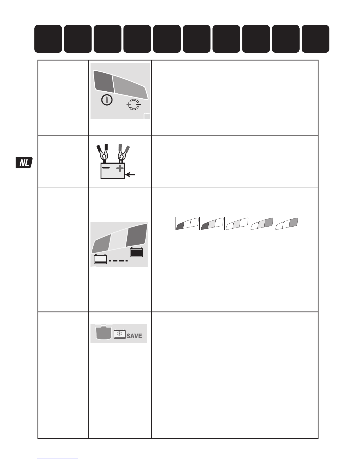
24
Bescher-ming
BMS RESET
2
1
de lader doet niets zolang de gebruiker niet handelt.
Led #2 OMGEKEERDE POLARITEIT: brandt wanneer de accu verkeerd is
aangesloten.
De lader is elektronisch beveiligd, zodat er niets wordt beschadigd. De
uitgang zal uitgeschakeld blijven tot de aansluitingen correct zijn.
BMS RESET: voor accu’s met een accubeheersysteem (BMS) dat tegen
volledige ontlading beschermt.
Koppel de lader los van de netvoeding. Wacht tot led #1a/1b uitgaat. Sluit de
lader opnieuw op de netvoeding aan. Gedurende 5 seconden wordt er een
speciale BMS-resetpuls afgegeven. Het programma gaat verder naar STAP 4.
STAP 1
Start met lage
spanning (accu ≥
0,5 V)
V
Controle van accuspanning - OptiMate Lithium wordt geactiveerd
wanneer de spanning van de aangesloten accu minstens 0,5 V is.
STAP 2
TEST vor het
laden
STAP 3
Tempera-
tuur controle
TEST LED
#6 : GROEN
#7: GEEL
#8 : ROOD
TEST
8
7
6
De TESTLEDS #6/7/8 geven de accustatus voorafgaand aan het laden weer.
Raadpleeg de tabel op pagina 2 voor een vergelijking van de gegevens van de
testleds met de geschatte laadstatus (SOC%).
8
7
6
90 100%603010%
13.3V 13.6V+ 13.13V13.00V12.80VV
8
7
7
6
0
0.5V
Tijdens de test:
de minimale laadtijd OPTIMALISEREN is ingesteld in functie van het
testresultaat. Dit kan variëren van 10 minuten voor een accu met een
laadstatus van 80% of meer tot 120 minuten voor een accu met een
laadstatus van 40% of minder.
De omgevingstemperatuur wordt gemeten om de laadspanningsparameters
te bepalen.
WAARSCHUWING LAGE TEMPERATUUR - LED #8 (rood) knippert: De op de
OptiMate Lithium gemeten temperatuur is lager dan -20°C (of -4°F), onder
de veilige laad- en ontlaadtemperatuur voor LiFePO4-accu's.
Het laden start na 10 seconden.
STAP 4
Zeer lage
spanning
recuperatie
STAP 5
Lage spanning
recuperatie
STAP 6
TEST
celschade
LED #3 : ROOD
3
BELANGRIJK: als deze modus wordt ingeschakeld, raadpleeg dan het
hoofdstuk
“ZEER PLATTE VERWAARLOOSDE ACCU’S” op de vorige pagina.
Deze modus wordt ingeschakeld wanneer de accu meer dan 90% ontladen is
of de spanning minder dan 12,8 V bedraagt. safeTº: de laadstroom wordt
automatisch aangepast volgens de spanning en de omgevingstemperatuur
die werden gemeten tijdens de test.
RECUPERATIE ZEER LAGE SPANNING voor accu’s tussen 0,6 V (0,75 V) en
8,8V: de stroom start bij 125 mA en loopt op tot 325 mA, afhankelijk van de
voortgang van het laadproces. Wanneer na 2 uur de spanning niet boven 8,8
V komt, wordt het laadproces onderbroken en brandt de TESTLED #8 (rood).
Dat betekent dat de accu mogelijk blijvende schade heeft opgelopen of dat
een professionele beoordeling vereist is.
RECUPERATIE LAGE SPANNING voor accu’s tussen 8,9 V en 12,8 V:
de maximale stroom is ingesteld op 1,25 A. De stroomopname van de accu
wordt gecontroleerd op abnormaal gedrag. Een LiFePO
4
-accu in goede staat
gaat in modus LADEN na 4 uur. Is dat niet het geval, dan wordt het
laadproces onderbroken en knippert de TESTLED #8 (rood). Dat betekent dat
de accu mogelijk blijvende schade heeft opgelopen of dat een professionele
beoordeling vereist is.
1091 2
3 4 5 6 7 8
OptiMate ‘365’
accuonderhoud
TEST na het
LADEN
Start met lage
spanning (0.5V)
TEST voor
het LADEN
Temperatuur-
controle
Lage spanning-
recuperatie
Lage spanning-
recuperatie/
celcontrole
TEST -
celschade
Cell-balancing
LADEN
OPTIMALI-
SEREN
Page 25
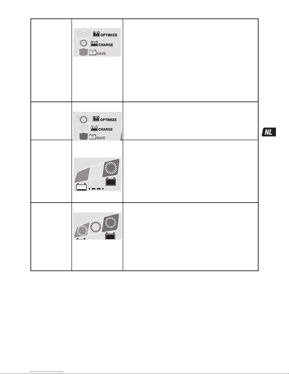
25
STAP 7
CHARGE
LED #4 : GEEL
4
Het safeTº-programma beperkt de laadstroom wanneer de op de OptiMate
Lithium gemeten temperatuur lager is dan 0 ºC / 32 ºF of hoger is dan 45 °C /
113 °F. Wanneer de temperatuur oorspronkelijk lager was dan 0 °C / 32 °F,
wordt de laadstroom alleen het eerste uur beperkt tot 325 mA. Daarna wordt
verondersteld dat de interne temperatuur van de accu is opgelopen tot het
normale temperatuurbereik.
Binnen het normale temperatuurbereik bepaalt het specifieke programma
ampmatic™ LiFePO
4
automatisch de efficiëntste laadstroom voor de
aangesloten accu op basis van de laadtoestand, de staat van de accu en het
opslagvermogen (Ah). De geleverde stroom kan tussen 1,25 A en 9,5 A liggen.
Voor accu’s met een opslagvermogen (Ah) van minder dan 10 Ah (8 Ah) wordt
de laadstroom automatisch verlaagd naar een gemiddelde dat gelijk is aan het
opslagvermogen (Ah). Zo krijgt een accu van 2,5 Ah/2.500 mAh een gemiddelde
van 2,5Amps.
OPMERKING: om veiligheidsredenen is de totale laadtijd beperkt tot 24 uur voor
de modus RECUPERATIE en de modus LADEN.
STAP 8
OPTIMALI-SEREN
LED #5 : GEEL
5
De modus OPTIMALISEREN start wanneer de spanning tijdens de volumelading
voor de eerste keer 14,4 V (18 V) heeft bereikt.
Het ampmatic™-stroombewakingsprogramma levert nu stroompulsen om de
afzonderlijke cellen in de accu te vereffenen en het laadniveau te optimaliseren.
Het laden moet binnen de minimale laadtijd die is ingesteld tijdens STAP 3 zijn
voltooid, maar wanneer de accu nog verder moet worden geladen, breidt het
programma de modus OPTIMALISEREN uit tot maximaal 2 uur.
STAP 9
TEST na Laden
LED #6 KNIPPERT
TEST
6
TEST na het laden: de levering van stroom aan de accu wordt gedurende
30minuten* onderbroken, zodat het programma kan bepalen of de accu
de lading kan vasthouden.
* ALS het laden is begonnen in RECUPERATIEMODUS (led #3 geeft aan dat de
accu sterk ontladen is) of de spanningsbehoudtest is verlengd tot 12 uur om
de conditie van de accu te bevestigen.
Het testresultaat (aangegeven met leds # 6, 7, 8) wordt realtime aangepast
aan de gemeten accuspanning. Raadpleeg de tabel ‘VROEGE TEKENEN VAN
ACCUPROBLEMEN’ op pagina 2 voor een vergelijking van de gegevens van de
testleds met de geschatte laadstatus (SOC%).
U vindt meer informatie in het hoofdstuk ‘OPMERKINGEN OVER DE
TESTRESULTATEN’.
STAP 10
OPTIMATE smart
ONDERHOUD
LED #6 / 7 / 8 AAN
8
7
6
Voor accu’s in een gezonde
conditie blijft led #6 (groen)
branden.
ONDERHOUDSCYCLUS: ledlampjes #6/7/8 branden constant
overeenkomstig de definitieve spanning die na STAP 7 gemeten is.
De ONDERHOUDSLAADCYCLUS bestaat uit laadperiodes van 30 minuten
gevolgd door telkens een rustperiode van 30 minuten. Tijdens de rustperiodes
is er geen laadstroom.
Tijdens de laadcycli van 30 minuten wordt er alleen stroom geleverd als de
accu lading heeft verloren.
ACCUONDERHOUD treedt in werking wanneer de lader detecteert dat de accu
veel lading verloren heeft. Het programma keert terug in de modus
OPTIMALISEREN (led #5) en voert vervolgens de spanningsbehoudtest en de
onderhoudslaadcyclus uit.
Lees het deel EEN LITHIUMACCU ONDERHOUDEN VOOR LANGERE PERIODEN.
OPMERKINGEN OVER DE TESTRESULTATEN:
1. Voor een ander testresultaat dan groen #6 (of groen #6 en geel #7 samen als de accu van het STD type met vuldoppen is), koppelt u
de accu los van het elektrische systeem dat hij ondersteunt en sluit de OptiMate opnieuw aan. Indien het testresultaat nu beter is, is het
stroomverlies gedeeltelijk te wijten aan een elektrisch probleem in het elektrische systeem en niet in de accu zelf. Als het resultaat nog
niet beter is, wordt aangeraden de accu naar een professionele servicewerkplaats met professioneel materiaal te brengen voor een
grondinger onderzoek.
2. Wanneer alleen LED #8 (rood) brandt of wanneer LED 7# (geel) en LED #8 (rood) beide branden (of gele LED alleen bij een verzegelde
accu), is er sprake van een ernstig probleem. De rode / gele+rode LEDs betekent dat de accuspanning na het laden niet wordt
vastgehouden of dat ondanks verschillende recuperatiepogingen de accu niet kon worden gerecupereerd. De oorzaak kan te vinden zijn
in de accu zelf, bijvoorbeeld een kortgesloten cel of volledige sulfatie of corrosie. Wanneer de accu nog op het elektrische systeem dat
hij ondersteunt is aangesloten kan de rode LED 8# ook een stroomverlies betekenen dat te wijten is aan versleten bedrading of een
defecte schakelaar of contact, of aan stroomverbruikende accessoires op hetzelfde circuit. Een plotse belasting die wordt ingeschakeld
terwijl de lader is aangesloten, kan ook leiden tot een aanzienlijk spanningsverlies van de accu.
3. GOED TESTRESULTAAT, maar de accu kan niet voldoende vermogen leveren: blijvende schade in de accu kan een overmatige
zelfontlading veroorzaken die niet kan worden opgespoord tijdens de testperiode van 12 uur. Koppel de accu los van de OptiMate.
Wacht minstens 48 uur voordat u de lader opnieuw aansluit, en houd de TESTresultaten tijdens de PREKWALIFICATIETEST in de gaten.
Page 26

26
DE ACCU ONDERHOUDEN VOOR LANGERE PERIODEN: De OptiMate onderhoudt een accu waarvan de basistoestand goed
is gedurende maanden aan een stuk. Controleer ten minste eenmaal per twee weken of de aansluitingen tussen de lader en accu
betrouwbaar zijn, en, in geval van accu's met vuldoppen op iedere cel, ontkoppel de accu van de lader, controleer het elektrolytpeil
en vul de cellen zo nodig bij (met gedestilleerd water, NIET met zuur); sluit de accu vervolgens weer op de lader aan. Neem
bovenstaande VEILIGHEIDSWAARSCHUWINGEN altijd in acht wanneer u de accu vastpakt of in de buurt van een accu bent.
ECO-STROOMBESPARINGSMODUS WANNEER DE LADER OP HET ELEKTRICITEITSNET IS AANGESLOTEN:
De vermogensomzetter gaat in ECO-modus wanneer de lader niet op een accu is aangesloten. Dit resulteert in een stroomopname van
minder dan 0,5 W, wat overeenkomt met een stroomverbruik van 0,012 kWh per dag. Als een accu op de lader is aangesloten is het
stroomverbruik afhankelijk van de stroombehoefte van de accu en het aangesloten voertuig / de elektronische circuits. Wanneer de
accu opgeladen is en het laadprogramma in de langetermijnonderhoudslaadmodus staat (om de accu 100% vol te houden) wordt het
totale stroomverbruik geraamd op 0,024 kWh per dag of minder.
BEPERKTE GARANTIE
TecMate (International) SA, Sint-Truidensesteenweg 252, B-3300 Tienen, België, staat deze beperkte garantie toe aan elke
eerste koper van dit toestel. Deze beperkte garantie gaat in op de dag van aankoop en is niet overdraagbaar. De drie jaar
geldige garantie aangeboden door TecMate (International) dekt alle erkende gebreken en arbeidskosten. Indien de lader defect
blijkt te zijn tengevolge van een constructiefout, zal de klant het toestel altijd vooraf en op eigen kosten terugsturen naar de
fabrikant of naar de nationale officiële verdeler, samen met een kopij van de aankoopfactuur (zie "NOTITIE"). In zulke gevallen,
zal de eenheid ter keuze van de fabrikant worden hersteld of worden vervangen.Onkosten tengevolge van een ongeval,
slordigheid, kwaadwilligheid, misbruik, niet conform gebruik volgens de aanwijzingen van de fabrikant, of herstellingen gedaan
door door TecMate niet-erkende verdelers, zijn niet gedekt door de garantie.
DE BEPERKTE GARANTIE SLUIT UITDRUKKELIJK ALLE VERDERE VERANTWOORDELIJKHEID UIT MET BETREKKING TOT
EVENTUELE SCHADEVERGOEDINGEN VAN WELKE AARD DAN OOK. UW STATUTAIRE RECHTEN WORDEN NIET BEÏNVLOED.
NOTITIE: Zie www.tecmate.com/warranty of contacteer warranty@tecmate.com.
Meer informatie overTecMate productenkanop www.tecmate.com worden gevonden.
Page 27

27
CARICABATTERIE DIAGNOSTICO AUTOMATICO PER BATTERIE LiFePO4
(LITIO FERRO-FOSFATO) DA 12,8 V. BATTERIE A 100 AH:
AVVERTENZA DI SICUREZZA E NOTE: SE NON LO SI È ANCORA FATTO, LEGGERE LE PAGINE
PRECEDENTI CONTRASSEGNATE COME "ISTRUZIONI DI SICUREZZA IMPORTANTI" PRIMA DI AZIONARE IL
CARICABATTERIE.
L’utilizzo di quest’apparecchio non è consentito alle persone (bambini inclusi) con ridotte capacità fisiche, sensoriali o
mentali, o con mancanza di esperienza e conoscenza, salvo sotto supervisione o a meno che non abbiano avuto istruzioni
riguardanti l'uso del apparecchio da parte di persone responsabili della loro sicurezza. I bambini devono essere sorvegliati
affinché non giochino con il apparecchio.
AVVERTENZA DI SICUREZZA E NOTE: Le batterie emettono GAS ESPLOSIVI – prevenire fiamme o scintille in prossimità
di batterie. Scollegare l'alimentazione CA prima di effettuare o interrompere connessioni con la batteria/CC. L'acido della batteria è
altamente corrosivo. Indossare abbigliamento protettivo ed occhiali, ed evitare il contatto. In caso di contatto accidentale, lavare
immediatamente con acqua e sapone. Controllare che i poli della batteria non siano allentati. Se così fosse, rivolgersi ad un esperto
per sistemarli. Se i poli della batteria sono corrosi, pulirli con una spazzola di rame; se sono unti oppure sporchi, pulirli con uno
straccio inumidito con detergente. Utilizzare il caricabatterie soltanto se i poli e i connettori di ingresso e di uscita sono in buona
condizione e non danneggiati. Se il cavo di ingresso è danneggiato, è essenziale farlo sostituire immediatamente dal produttore, dal
riparatore autorizzato o da un'officina qualificata, per evitare pericoli. Proteggere il caricabatterie da acido, fumi acidi e umidità sia
durante l'uso che nell'immagazzinamento. I danni derivanti da corrosione, ossidazione o cortocircuiti elettrici interni non sono
coperti dalla garanzia. Distanziare il caricabatterie dalla batteria durante la carica per evitare la contaminazione o l'esposizione
all'acido o ai vapori acidi. Se lo si utilizza nell'orientamento orizzontale, collocare il caricabatterie su una superficie dura e piana, ma
NON su plastica, tessuto o cuoio. Utilizzare i fori di fissaggio forniti nella base dell'involucro per collegare il caricabatterie a
qualunque superficie verticale pratica e comoda.
ESPOSIZIONE AI LIQUIDI: Questo caricabatterie è destinato a sopportare l'esposizione ai liquidi rovesciati o spruzzati
accidentalmente sull'involucro dall'alto, o a una leggera pioggia. L'esposizione prolungata alla pioggia è sconsigliata e si otterrà una
maggiore durata riducendo al minimo tale esposizione. Un guasto del caricabatterie dovuto all'ossidazione derivante dalla
penetrazione eventuale di liquido nei componenti elettronici, nei connettori o nelle spine non è coperto da garanzia.
CONNESSIONE DEL CARICABATTERIE ALLA BATTERIA
1. Scollegare l'alimentazione CA prima di effettuare o di eliminare delle connessioni alla batteria/CC.
2. Se si carica la batteria del veicolo con i morsetti della batteria, prima di effettuare le connessioni verificare che i morsetti della
batteria possano essere posizionati in modo sicuro e protetto, distanti da cavi e tubi metallici circostanti o dal telaio. Effettuare
le connessioni procedendo come segue: per prima cosa, collegare il terminale della batteria non collegato al telaio (solitamente
positivo), quindi collegare l'altro morsetto della batteria (solitamente negativo) al telaio, mantenendo le distanze dalla batteria e
dalla linea del combustibile. Scollegare sempre nella sequenza contraria.
3. Quando si carica una batteria smontata dal veicolo utilizzando i morsetti della batteria, posizionare quest'ultima in una zona
ben ventilata. Collegare il caricabatterie alla batteria: morsetto ROSSO a terminale POSITIVO (POS, P o +) e morsetto NERO a
terminale NEGATIVO (NEG, N o –).Verificare che le connessioni siano salde e sicure. Un buon contatto è fondamentale.
ESECUZIONE DELLA CARICA
TEMPO DI CARICA : La temperatura ambiente influisce sul tempo di carica. Il programma safeTº limita la corrente di carica se
la temperatura misurata su OptiMate Lithium è inferiore a 0ºC / 32ºF o superiore a 45ºC / 113 F. All'interno del normale intervallo di
temperatura il programma specifico
LiFePO
4
ampmatic™ stabilisce automaticamente il livello più efficiente di corrente di carica
per la batteria collegata in base al suo stato di carica, allo stato di funzionamento e alla capacità di conservazione dell'elettricità
(Ah). La corrente erogata può essere di qualunque livello da 1,25 A a 5 A.
Tempo di carica su una batteria scarica ma senza danni:
Per le batterie con valore nominale da 2,5 Ah a 5 Ah: da 60 a 120 minuti per passare al test di mantenimento della carica.
Per le batterie con capacità superiore a 5 Ah: leggermente meno del 25% del valore nominale Ah della batteria, pertanto per una
batteria da 50 Ah non dovrebbero essere necessarie più di 5 ore per passare al test di mantenimento della carica.
Per le batterie molto scariche potrebbe essere necessario molto più tempo.
SICUREZZA
Page 28
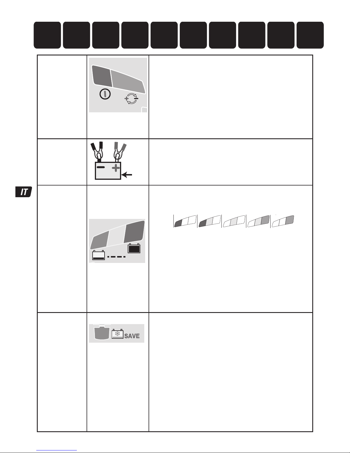
28
Protezione
RESET BMS
2
1
Il caricabatterie non entra in funzione se non tramite l’intervento
dell’utente.
PROTEZIONE CONTRO L’INVERSIONE DI POLARITÀ DEL LED 2: si accende
quando i collegamenti della batteria non sono stati effettuati correttamente. Il
caricabatterie è dotato di protezione elettronica, pertanto non può subire
danni. L’uscita resta disabilitata fino alla correzione dell’errore di
collegamento.
RESET BMS: per batterie con un sistema di gestione della batteria (BMS,
Battery Management System) che protegge dallo scaricamento completo.
Scollegare il caricabatterie dall’alimentazione di rete. Attendere che i LED
1a/1b si spengano. Ricollegare all’alimentazione di rete. Uno speciale impulso
di reset BMS viene trasmesso per un massimo di 5 secondi. Il programma
dovrebbe proseguire alla FASE 4.
FASE 1
V
Controllo della tensione della batteria - la OptiMate Lithium si
attiva se la tensione della batteria collegata è almeno di 0,5 Volt.
FASE 2
TEST prima della
carica
FASE 3
Controllo della
temperatura
LED DI TEST
6: VERDE
7: GIALLO
8: ROSSO
TEST
8
7
6
I LED DI TEST 6/7/8 indicano lo stato della batteria prima della carica.
Consultare la tabella a pag. 2 per abbinare l’indicazione del LED DI TEST a
uno stato di percentuale di carica (SOC%) stimato
8
7
6
90 100%603010%
13.3V 13.6V+ 13.13V13.00V12.80VV
8
7
7
6
0
0.5V
Durante il test:
OTTIMIZZARE il tempo di carica minimo regolato in conformità al test, che
può variare da 10 minuti per una batteria all'80% a un tempo di carica
superiore a 120 minuti per una batteria con uno stato di carica pari o inferiore
al 40%.
Viene rilevata la temperatura ambiente per determinare i parametri di
tensione di carica.
AVVERTENZA DI TEMPERATURA INSUFFICIENTE - LED #8 (rosso)
lampeggiante: La temperatura misurata su OptiMate Lithium è inferiore a
-20ºC o a -4ºF, al di sotto della zona di carica E scarica sicura per le
batterie LiFePO4.
Il programma inizia dopo 10 secondi.
FASE 4
RECUPERO a
tensione ultra
bassa
FASE 5
Basso
voltaggio
recupero
FASE 6
TEST danni alla
cella
LED #3 : ROSSO
3
IMPORTANTE: se si attiva questa modalità leggere la sezione BATTERIE
COMPLETAMENTE SCARICHE nella pagina precedente.
Questa modalità si attiva se la batteria è stata scaricata più del 90% / la
tensione è inferiore a 12,8 V. safeTº: la corrente di carica viene regolata
automaticamente in base alla tensione e alla temperatura ambiente misurate
durante il test.
RECUPERO A BASSISSIMA TENSIONE per batterie tra 0,6 V (0,75 V) e 8,8V:
la corrente inizia a 125 mA e aumenta a 325 mA a seconda del progresso
della carica. Se la tensione non aumenta oltre gli 8,8 V entro 2 ore, la carica
viene sospesa e il LED DI TEST 8 (rosso) lampeggia, a indicare che la batteria
potrebbe aver subito un danno permanente o che è necessaria una
valutazione professionale.
RECUPERO A BASSA TENSIONE per batterie tra 8,9 V e 12,8 V:
la corrente massima è impostata su 1,25 A. L’assorbimento della carica della
batteria viene controllato per il comportamento anomalo. Una batteria
LiFePO
4
in buone condizioni passa alla modalità di CARICA entro 4 ore,
altrimenti la carica viene sospesa e il LED DI TEST 8 (rosso) lampeggia, a
indicare che la batteria può aver subito un danno permanente o che è
necessaria una valutazione professionale.
1091 2
3 4 5 6 7 8
Manutenzione
OptiMate ‘365’
TEST dopo
la carica
Accensione
a bassa
tensione (0.5V)
TEST prima
della carica
Controllo
della
temperatura
TEST - danni
alla cella
RECUPERO a
tensione
ultra bassa
BASSO VOLTAGGIO
RECUPERO
/ monitoraggio
delle celle
CARICA per
equalizzazione
delle celle
OTTIMIZZA-
ZIONE
Page 29
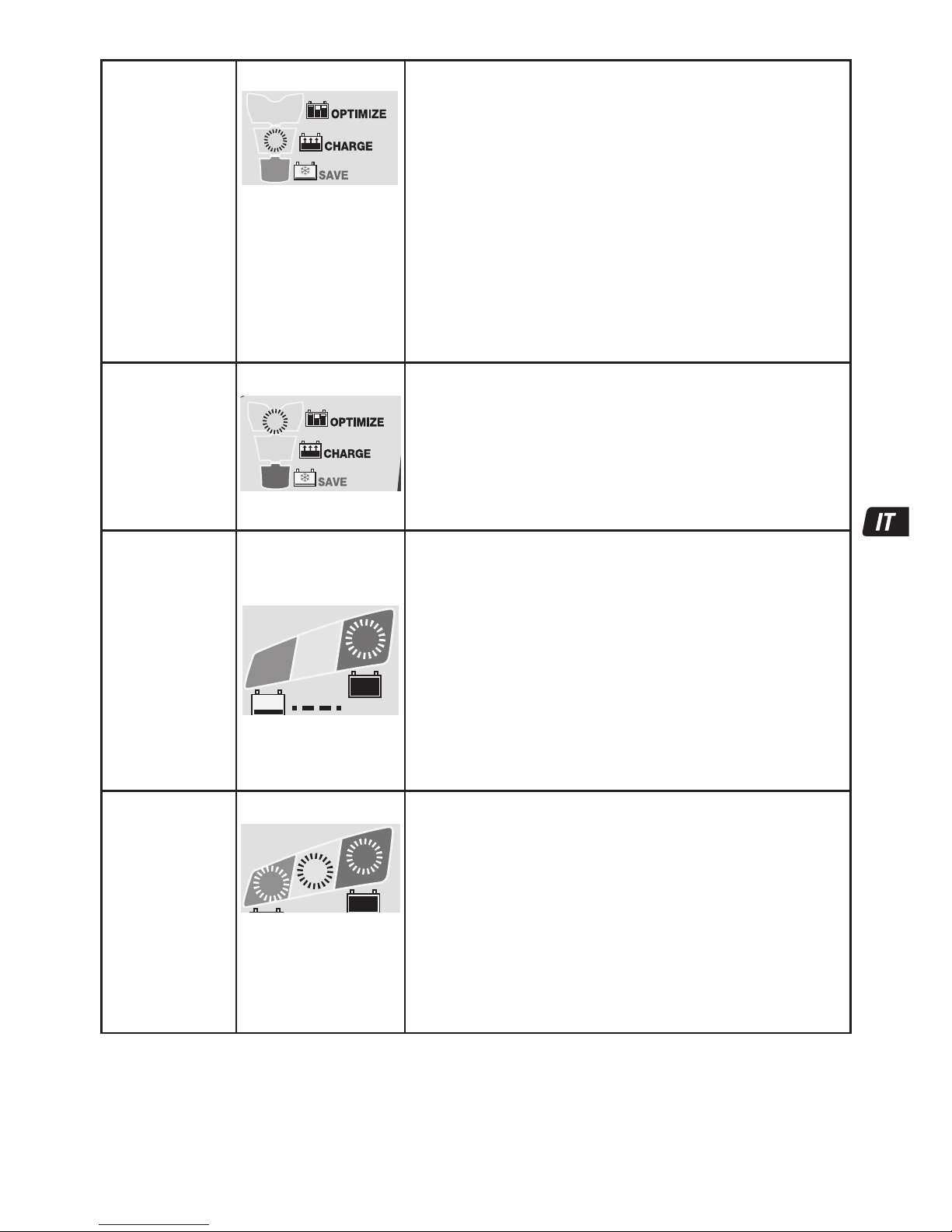
29
FASE 7
CARICA
LED #4 : GIALLO
4
Il programma safeTº limita la corrente di carica se la temperatura misurata
su OptiMate Lithium è inferiore a 0 °C/32 °F o superiore a 45 °C/113 °F. Se
la temperatura inizialmente era inferiore a 0 °C/32 °F, la corrente di carica
viene limitata a 325 mA solo per la prima ora, dopodiché la batteria
dovrebbe aumentare la propria temperatura interna entro la normale fascia
di temperatura.
Nell’ambito della normale fascia di temperatura, il programma specifico
LiFePO
4
ampmatic™ stabilisce automaticamente il livello più efficiente di
corrente di carica per la batteria collegata in base al suo stato di carica, allo
stato di funzionamento e alla capacità di conservazione dell’elettricità (Ah).
La corrente erogata può variare da 1,25 A a 9,5 A.
Per le batterie con capacità inferiore a 10 Ah (8 Ah), la corrente di carica
viene regolata automaticamente a un livello inferiore a una media pari alla
capacità Ah della batteria;
ad esempio, una batteria da 2,5 Ah/2.500 mAh riceve una media di 2,5 A.
NOTA: per motivi di sicurezza, il limite di tempo di carica totale è di 24 ore
per le modalità di RECUPERO e CARICA.
FASE 8
OTTIMIZ-
ZAZIONE
LED #5 : GIALLO
5
La modalità di OTTIMIZZAZIONE inizia quando la tensione raggiunge i 14,4 V (18
V) per la prima volta durante la modalità di CARICA principale BULK.
Il programma di controllo di corrente
ampmatic™ trasmette impulsi di
corrente per equalizzare le celle individuali all'interno della batteria e ottimizzare
il livello di carica.
La carica dovrebbe essere completata entro il tempo di carica minimo impostato
durante la FASE 3, ma se la batteria richiede un ulteriore caricamento, il
programma estenderà il modo di OTTIMIZZAZIONE della carica a un massimo di
2 ore.
FASE 9
TEST dopo
la carica
LED #6
LAMPEGGIANTE
TEST
6
TEST dopo la carica: l’erogazione della corrente alla batteria viene
interrotta per 30minuti* per consentire al programma di determinare la
capacità della batteria di mantenere la carica.
* SE la carica inizia in modalità RECUPERO (LED 3, a indicare una batteria
completamente scarica) o la prova di ritenzione della tensione viene
prolungata
a 12 ore per verificare lo stato di salute della batteria.
Il risultato del TEST (indicato sui LED 6, 7, 8) viene regolato in tempo reale in
base alla tensione misurata della batteria. Consultare la tabella
“SEGNALAZIONE TEMPESTIVA DEI PROBLEMI DELLA BATTERIA” a pag. 2 per
abbinare l'indicazione del LED DI TEST a uno stato di percentuale di carica
(SOC%) stimato.
Maggiori informazioni sono fornite nella sezione “NOTE SUI RISULTATI DEL
TEST”.
FASE 10
MANUTEN- ZIONE
OPTIMATE smart
LED #6 / 7 / 8 ACCESI
8
7
6
Se le batterie si trovano in buono
stato, il LED 6 (verde) rimane
acceso.
CARICA DI MANTENIMENTO: LED 6/7/8 con luce fissa in in base alla
tensione finale misurata al termine della FASE 7.
Il CICLO DI CARICA DI MANTENIMENTO consiste in periodi di carica di 30
minuti seguiti da e alternati con periodi di “riposo” di 30 minuti, durante i
quali non vi è corrente di carica.
Durante i cicli di carica di 30 minuti la corrente viene erogata solo se la
batteria ha perso carica.
Il CICLO DI RIPRISTINO DELLA BATTERIA viene eseguito se il caricabatterie
rileva che la batteria ha perso una parte significativa della carica. Il
programma torna alla modalità OTTIMIZZAZIONE (LED 5), quindi passa alla
prova di ritenzione della tensione e al ciclo di carica di mantenimento.
Leggere la sezione MANTENIMENTO DELLA BATTERIA AL LITIO PER PERIODI
PROLUNGATI.
NOTE SUI RISULTATI DEL TEST:
1. Per risultati di test diversi dal LED verde #6 (o LED verde #6 e LED giallo #7 insieme se la batteria è di tipo STANDARD con tappi di
riempimento), scollegare la batteria dal sistema elettrico che supporta e ricollegare l’OptiMate. Se questa volta si ottiene un risultato di
test migliore, ciò suggerisce che le perdite di potenza sono parzialmente dovute a un problema elettrico nel sistema elettrico e non nella
batteria. Se il risultato scarso persiste, si consiglia di portare la batteria a un'officina di assistenza dotata di apparecchiature
professionali per un'indagine più approfondita.
Page 30

30
2. Se il LED rosso #8 si accende da solo o se il il LED giallo #7 e quello rosso #8 si accendono simultaneamente (o il LED giallo da solo
in una batteria sigillata), si è in presenza di un problema grave. I LED rosso / giallo+rosso indicano che dopo la carica la tensione della
batteria non viene mantenuta o che malgrado i tentativi di recupero la batteria era irrecuperabile. Ciò può essere dovuto a un difetto
della batteria, come una cella cortocircuitata o la solfatazione totale, o, nel caso di una batteria ancora collegata al sistema elettrico, il
LED rosso #7 potrebbe segnalare una perdita di corrente tramite collegamenti deteriorati, un interruttore o un contatto danneggiato, o
ancora accessori in circuito che consumano corrente. Anche un consumo improvviso che viene acceso mentre il caricabatterie è
collegato può far scendere notevolmente la tensione della batteria.
3. BUONI RISULTATI DI TEST, ma la batteria non eroga potenza sufficiente: danni permanenti all'interno della batteria possono provocare
uno scaricamento eccessivo che non viene rilevato entro il periodo di test di 12 ore. Scollegare la batteria dal OptiMate. Attendere
almeno 48 ore, quindi ricollegarla e osservare il risultato del TEST DI PREQUALIFICAZIONE.
MANTENIMENTO DELLA BATTERIA PER PERIODI PROLUNGATI: OptiMate terrà in vita per mesi una batteria che si
presenti fondamentalmente in buone condizioni. Almeno una volta ogni due settimane, controllare che le connessioni tra il
caricabatterie e la batteria siano sicure e, in caso di batterie con tappi di riempimento, disconnettere la batteria dal caricabatterie,
controllare il livello di elettrolito e, se necessario, riempire le celle (con acqua distillata, NO acido), quindi riconnetterla. Quando si
maneggiano le batterie o anche solo in presenza di batterie, leggere sempre con cura le AVVERTENZE DI SICUREZZA qui riportate.
MODO ECOLOGICO DI RISPARMIO ENERGETICO QUANDO IL CARICABATTERIE È COLLEGATO ALLA RETE CA:
Il convertitore di alimentazione passa in modo ECO quando il caricabatterie non è collegato ad alcuna batteria e consente un
assorbimento di alimentazione molto limitato, inferiore a 0,5 W, pari a un consumo energetico di 0,012 kWh al giorno. Quando una
batteria viene collegata al caricabatterie, il consumo energetico dipende dalla domanda di corrente elettrica della batteria e della
circuiteria elettronica/del veicolo connessa. Dopo aver caricato la batteria e una volta portato il programma di carica in modo di carica di
mantenimento a lungo termine (per mantenere la batteria carica al 100%), si stima che il consumo energetico totale sarà pari o inferiore
a 0,024 kWh al giorno.
GARANZIA LIMITATA
TecMate (International) S.A., Sint-Truidensesteenweg 252, B-3300 Tienen, Belgio riconosce questa garanzia limitata agli
acquirenti originali al dettaglio di questo strumento. Questa garanzia limitata non e’ trasferibile. TecMate (International)
garantische il carica per tre anni dalla data di acquisto al dettaglio contro difetti di materiale o di manodopera. Se tali difetti
fossero riscontrati lo strumento verra’ riparato o sostituito a discrezione dell’Azienda. Sara’ obbligo dell’acquirente rispedire lo
strumento, a proprie spese e cura, con il tagliando di acquisto (vede "NOTA"), al produttore o al distributore autorizzato. Questa
garanzia limitata e’ nulla se il prodotto e’ maltrattato o usate male, soggetto ad incuria nel maneggiamento, o riparato da
chiunque esclusi il produttore o il distributore autorizzato. Il produttore non riconosse altre garanzie se non questa limitata
garanzia ed esclude espressamente ogni implicata garanzia che includa garanzie per conseguenti danneggiamenti.
QUESTA È LA SOLA ED ESPRESSAMENTE LIMITATA GARANZIA E L'AZIENDA PRODUTTRICE NE ASSUME NE AUTORIZZA ALCUNO
AD ASSUMERE O FARE ALTRE CONCESSIONI CHE RIGUARDINO IL PRODUTTORE, DIVERSAMENTE DA QUESTA. I VOSTRI DIRITTI
STATUTARI NON SONO COMMOVENTI.
NOTA: Vede www.tecmate.com/warranty o contattate warranty@tecmate.com
Si può trovare più informazione sui prodotti di TecMate da www.tecmate.com.
Page 31

31
Automatisk diagnostisk laddare för 12,8 V LiFePO4-batterier
(litiumjärnfosfat-batterier). Batterier till 100 Ah:
SÄKERHETSVARNING OCH SÄKERHETSINFORMATION: OM DU INTE REDAN HAR LÄST IGENOM
FÖREGÅENDE SIDOR, MÄRKTA MED ”VIKTIGA SÄKERHETSANVISNINGAR”, MÅSTE DU GÖRA DET INNAN DU
ANVÄNDER LADDAREN.
Den här apparaten ska inte användas av personer (inklusive barn) med nedsatt fysisk, sensorisk eller
mental förmåga, eller personer som saknar erfarenhet och kunskap, såvida de inte hålls under uppsikt
eller instrueras om hur apparaten används av en person som ansvarar för deras säkerhet. Håll barn under
uppsikt för att se till att de inte leker med apparaten.
SÄKERHETSVARNING OCH SÄKERHETSINFORMATION:
Batterier utsöndrar EXPLOSIVA GASER. Förhindra öppen eld eller
gnistor i närheten av batterier. Koppla ifrån spänningsförsörjningen (växelström) innan du ansluter eller lossar likströms- eller
batterianslutningar. Batterisyra är mycket frätande. Bär skyddskläder och skyddsglasögon och undvik kontakt. Om du av misstag
kommer i kontakt med batterisyran måste du genast tvätta med tvål och vatten. Kontrollera att batteriets elektroder inte sitter löst. I
så fall måste batteriet kontrolleras av en expert. Om batteriets elektroder är rostiga rengör du dem med en kopparborste. Om de är
oljiga eller smutsiga tvättar du dem med en trasa fuktad med rengöringsmedel. Använd endast laddaren om in- och utkablarna och
kontaktdonen är oskadda och i gott skick. Om inkabeln är skadad är det mycket viktigt att den genast byts ut av tillverkaren,
tillverkarens auktoriserade serviceombud eller en kvalificerad verkstad, så att fara inte uppstår. Skydda laddaren mot syra, syraånga
och fukt, både vid användning och förvaring. Skador till följd av korrosion, oxidering eller invändig elektrisk kortslutning täcks inte av
garantin. Håll laddaren på avstånd från batteriet under laddning för att undvika kontaminering genom eller exponering för syra eller
sura ångor. Om du använder laddaren i horisontellt läge måste du placera den på en hård, plan yta och INTE på plast, tyg eller läder.
Använd fixeringshålen i höljets botten för att fästa laddaren på en lämplig och stabil lodrät yta.
VÄTSKEEXPONERING: Laddaren är konstruerad för att stå emot lätt regn och vätskor som av misstag spills eller skvimpas ut på
höljet ovanifrån. Längre exponering för regn är dock inte att rekommendera, och servicelivslängden ökar om laddaren inte utsätts för
sådant. Fel på laddaren, som ett resultat av oxidering orsakad av att vätska trängt in i de elektroniska komponenterna, kontaktdonen
eller stickpropparna, täcks inte av garantin.
ANSLUTA LADDAREN TILL BATTERIET
1. Koppla ifrån spänningsförsörjningen (växelström) innan du ansluter eller lossar likströms- eller batterianslutningar.
2. När ett batteri laddas i fordonet med batterikabelskor måste du, innan du ansluter, kontrollera att batteriklämmorna kan
placeras säkert och att de inte vidrör omkringliggande ledningar, metallrör eller chassiet. Anslut i följande ordning: Anslut först
till den batteriklämma som inte är ansluten till chassiet (normalt positiv), anslut sedan den andra batteriklämman (normalt
negativ) till chassiet på ett tillräckligt avstånd från batteriet och bränsleledningar. Lossa alltid anslutningarna i motsatt
ordningsföljd.
3. När ett batteri ska laddas utanför fordonet med batteriklämmorna måste det placeras i ett utrymme med god ventilation. Anslut
laddaren till batteriet: Anslut den RÖDA klämman till PLUS-polen (POS, P eller +) och den SVARTA klämman till MINUS-polen
(NEG, N eller –).Kontrollera att anslutningarna sitter korrekt och säkert. God kontakt är viktigt.
ÖVERGÅNG TILL LADDNING
LADDNINGSTID : Laddningstiden påverkas av omgivningstemperaturen. safeTº-programmet begränsar laddningsströmmen om
temperaturen, uppmätt vid OptiMate Lithium-laddaren, understiger 0ºC eller överstiger 45ºC. Om temperaturen ligger inom det
normala intervallet bestämmer det
LiFePO
4
-specifika ampmatic™-programmet automatiskt vilken laddningstakt som är mest
effektiv för det anslutna batteriet utifrån batteriets laddningsstatus, skick och elektriska laddningskapacitet (Ah-kapacitet). Den
ström som levereras kan variera mellan 1,25 A och 5 A.
Laddningstid för ett urladdat men i övrigt oskadat batteri:
För batterier med en märkkapacitet på 2,5 Ah till 5 Ah: 60 till 120 minuter för att nå spänningsgradstestläget.
För batterier med en märkkapacitet på över 5 Ah: Något mindre än 25 % av batteriets Ah-kapacitet, vilket innebär att det inte bör
ta mer än 5 timmar för ett 50 Ah-batteri att nå spänningsgradstestläget.
För nästan helt urladdade batterier kan laddningen ta betydligt längre tid.
SÄKERHET
Page 32

32
Skydd
ÅTER-
STÄLLNING
AV BMS
2
1
Laddaren aktiveras inte utan att användaren först gör något.
LED #2 OMKASTAD POLARITET: Lyser när batterianslutningarna är felaktigt
anslutna. Laddaren är elektroniskt skyddad så att det inte uppstår några skador,
och utgången förblir inaktiv tills anslutningarna har korrigerats.
ÅTERSTÄLLNING AV BMS: För batterier med ett BMS (batterihanteringssystem) som
skyddar mot djupurladdning.
Koppla från strömmen till laddaren. Vänta tills LED #1a/1b slocknar. Koppla på
strömmen igen. En BMS-återställningspuls ges i upp till 5 sekunder. Programmet
fortsätter då till STEG 4.
STEG 1
Lågspännin-
gsstart
(Batt. ≥
0,5V)
V
Batterispänningskontroll – OptiMate Lithium aktiveras om den anslutna
batterispänningen är minst 0,5 V.
STEG 2
TESTA före
laddning
STEG 3
Temperatur-
kontroll
TEST-lysdiod
#6: GRÖN
#7: GUL
#8: RÖD
TEST
8
7
6
TEST-lysdiod 6/7/8 indikerar batteriets skick före laddning. Använd tabellen på sidan
2 för att matcha TEST-lysdiodernas indikeringar mot en beräknad laddningsgrad
(SOC%).
8
7
6
90 100%603010%
13.3V 13.6V+ 13.13V13.00V12.80VV
8
7
7
6
0
0.5V
Under testets gång:
OPTIMERA Inställningen för kortaste laddningstid är baserad på testresultatet, och
varierar mellan 10 minuter för ett batteri med minst 80 % laddning till 120 minuter
för ett batteri med högst 40 % laddning.
Omgivningstemperaturen mäts för att bestämma parametrarna för
laddningsspänningen.
VARNING FÖR LÅG TEMPERATUR - LED #8 (röd) blinkar: Temperaturen som
uppmätts vid OptiMate Lithium-laddaren understiger -20ºC, vilket är utanför
intervallet för säker laddning OCH urladdning av LiFePO
4
-batterier.
Laddningen påbörjas efter 10 sekunder.
STEG 4
EXTREMT
LÅG SPÄNNING
ÅTERSTÄLL-
NING
STEG 5
LÅG SPÄNNING
ÅTERSTÄLL-
NING
STEG 6
TEST – skadad
cell
Lysdiod #3 : ROD
3
VIKTIGT! Läs igenom avsnittet ”URLADDADE OCH SKADADE BATTERIER” på nästa
sida om detta läge aktiveras.
Detta läge aktiveras om batteriet är urladdat till mer än 90 %, eller om spänningen
understiger 12,8 V. safeTº: Laddningsströmmen justeras automatiskt efter den
spänning och omgivningstemperatur som uppmättes under testet.
SKYDD VID MYCKET LÅG SPÄNNING för batterier mellan 0,6 V (0,75 V) och 8,8
V: Laddningsströmmen är till att börja med 125 mA och ökar sedan till 325 mA,
beroende på hur laddningen fortskrider. Om spänningen inte överstiger 8,8 V inom 2
timmar avbryts laddningen och TEST-lysdioden #8 (röd) börjar blinka, vilket indikerar
att batteriet kan ha drabbats av bestående skador eller att det måste utvärderas av
en sakkunnig.
SKYDD VID LÅG SPÄNNING för batterier mellan 8,9 V och 12,8 V: Maxströmmen
är satt till 1,25 A. Batteriets laddningsbenägenhet övervakas för att det ska gå att
upptäcka avvikande beteenden. Ett oskadat LiFePO
4
-batteri övergår till LADDNINGSläge inom 4 timmar, annars avbryts laddningen och TEST-LED #8 (röd) börjar blinka,
vilket indikerar att batteriet kan ha drabbats av bestående skador eller att det måste
utvärderas av en sakkunnig.
1091 2
3 4 5 6 7 8
OptiMate-
underhåll ‘365’
AV TEST efter
LADDNING
Lågspänning
Start (0,5 V)
TEST före
laddning
Temperatur-
kontroll
Extremt LÅG
SPÄNNING –
ÅTERSTÄLLNING
LÅG SPÄNNING –
ÅTERSTÄLLNING/
cellövervakning
TEST –
skadad cell
Cellutjämnande
LADDNING
OPTIMERING
Page 33

33
STEG 7
LADDNING
Lysdiod #4 : GUL
4
SafeTº-programmen begränsar laddningsströmmen om den uppmätta
temperaturen vid OptiMate Lithium är under 0 ºC och över 45 ºC. Om temperaturen
är under 0 °C redan från början begränsas laddningsströmmen till 325 mA enbart
under den första timmen. Därefter förväntas batteriets invändiga temperatur ha stigit
till ett värde som ligger inom det normala temperaturintervallet.
När temperaturen ligger inom det normala intervallet bestämmer det LiFePO
4
specifika ampmatic™-programmet automatiskt vilken laddningstakt som är mest
effektiv för det anslutna batteriet utifrån batteriets laddningsstatus, skick och
elektriska laddningskapacitet (Ah-kapacitet). Den ström som levereras kan variera
mellan 1,25 A och 9,5 A.
För batterier med en elektrisk laddningskapacitet (Ah-kapacitet) på mindre än 10 Ah
(8 Ah) justeras laddningsströmmen automatiskt ned till ett genomsnittligt värde som
motsvarar batteriets Ah-kapacitet. Exempelvis matas ett 2,5 Ah-/2 500 mAh-batteri
med en laddningsström på i genomsnitt 2,5 A.
OBS! Av säkerhetsskäl finns det en allmän laddningsgräns på 24 timmar för
SKYDDS- och LADDNINGS-lägena.
STEG 8
OPTIMERING
Lysdiod #5 : GUL
5
Läget OPTIMIZE (Optimera) startar när spänningen når 14,4 V (18 V) för första
gången under BULK CHARGE-fasen (Bulkladdning).
Ampmatic™-programmet skickar nu strömpulsar för att spänningsutjämna de
enskilda battericellerna i batteriet och optimera laddningsnivån.
Laddningen bör slutföras inom den angivna kortaste laddningstiden under STEG 3,
men om batteriet kräver mer laddning förlängs OPTIMIZE-laddningen upp till de
maximala 2timmarna.
STEG 9
TEST efter
laddnin
Lysdiod #6
BLINKAR
TEST
6
TEST efter laddning: Leverans av strömmen till batteriet avbryts i 30 minuter*
för att programmet ska kunna avgöra batteriets förmåga att behålla laddning.
* OM laddningen påbörjades i SPARA-läget (lysdiod #3 för ett djupurladdat batteri)
eller om spänningsgradstestet utökas till 12 timmar för att kontrollera batteriets
skick.
Testresultatet (som visas med lysdioderna 6, 7 och 8) justeras i realtid baserat på
uppmätt batterispänning. Använd tabellen ”TIDIG VARNING FÖR BATTERIPROBLEM”
på sidan 2 för att tolka lysdiodernas signaler för den beräknade laddningsgraden
(SOC%).
Mer information finns i avsnittet ”INFORMATION OM TESTRESULTAT”.
STEG 10
OPTIMERING
smart
UNDERHÅLL
Lysdiod #6 / 7 / 8 PÅ
8
7
6
Om batteriet är i gott skick
fortsätter lysdiod #6 (grön) att
lysa.
UNDERHÅLLSLADDNING: LED #6/7/8 lyser enligt slutgiltig spänning som
uppmättes när STEG 7 avslutades.
UNDERHÅLLSLADDNINGSCYKELN utgörs av laddningsperioder om 30 minuter som
omväxlande följs av viloperioder om 30 minuter. Under viloperioderna tillförs ingen
laddningsström.
Under den 30 minuter långa laddningscykeln levereras ström endast om batteriet
inte har någon laddning.
BATTERIPÅBÄTTRINGSCYKELN aktiveras om laddaren upptäcker att batteriet har
tappat laddning. Programmet återgår då till OPTIMERINGS-läget (LED #5) och går
sedan vidare till spänningsgradstestet och underhållsladdningscykeln.
Läs avsnittet LÅNGSIKTIGT LITIUMBATTERIUNDERHÅLL.
INFORMATION OM TESTRESULTAT:
1. Om du får ett annat testresultat än grön LED #6 (eller grön LED #6 och gul LED #7 tillsammans om det är ett STD-batteri med
påfyllningslock) bör du koppla bort batteriet från det elsystem som det stöder och sedan ansluta OptiMate-laddaren igen. Blir
testresultat bättre nu antyder det att effektförlusterna delvis beror på ett elektriskt problem i elsystemet, och inte i själva batteriet.
Består det dåliga resultatet rekommenderar vi att du lämnar in batteriet för närmare granskning på en serviceverkstad som har tillgång
till professionell utrustning.
2. Om den röda LED #8 lyser ensam, eller om den gula LED #7 och den röda LED #8 lyser samtidigt (eller om den gula LED-lampan
lyser ensam när ett slutet batteri används), tyder det på ett allvarligt fel. Den röda/den gula + röda LED-lampan indikerar att batteriet
inte kan hålla spänningen efter att det laddats, eller att det inte gick att återställa batteriet trots flera försök. Detta kan bero på ett fel i
själva batteriet, till exempel en kortsluten cell eller total sulfatering. Om batteriet fortfarande är anslutet till det elsystem som det stödjer
kan den röda LED #8 också indikera strömförluster till följd av dåliga kablar, strömslukande tillbehör eller angripna strömbrytare eller
kontakter. En plötslig belastning medan laddaren är ansluten kan också leda till att batterispänningen minskar betydligt.
Page 34

3434
3. GODA TESTRESULTAT, men batteriet kan inte leverera tillräckligt med ström: Permanenta skador inuti batteriet kan orsaka en
omfattande självurladdning som inte upptäcks inom testperioden på 12 timmar. Koppla bort batteriet från OptiMate-laddaren. Återanslut
batteriet när det gått minst 48 timmar och läs av resultatet under FÖRBEDÖMNINGSTESTET.
LÅNGSIKTIGT BATTERIUNDERHÅLL: OptiMate kan bevara ett batteri i gott skick i flera månader i taget. Du bör kontrollera att
kopplingen mellan laddaren och batteriet är korrekt minst varannan vecka och, om det är ett batteri med påfyllningslock på varje
cell, bör du även koppla från batteriet från laddaren, kontrollera elektrolytnivån och vid behov fylla på cellerna (med destillerat
vatten, INTE syra) och sedan återansluta dem. Ta alltid hänsyn till de SÄKERHETSVARNINGAR som beskrivs ovan när du hanterar
eller befinner dig i närheten av batterier.
STRÖMSPARLÄGE NÄR LADDAREN ÄR ANSLUTEN TILL VÄXELSTRÖMSFÖRSÖRJNINGEN:
Strömomvandlaren går över till strömsparläge när laddaren inte är ansluten till något batteri. Det gör att den drar mycket lite ström:
mindre än 0,5 W, vilket motsvarar en energiförbrukning på 0,012 kWh per dag. När ett batteri är anslutet till laddaren beror
energiförbrukningen på den ström som batteriet och det anslutna fordonet/de elektroniska kretsarna kräver. När batteriet har
laddats och laddaren har övergått till läget långvarig underhållsladdning (vilket håller batteriet fulladdat) uppgår den totala
energiförbrukningen till ungefär 0,024 kWh, eller ännu mindre, per dag.
INSKRÄNKT GARANTI
TecMate (International) NV, Sint-Truidensesteenweg 252, B-3300 Tienen, Belgien, utfärdar denna garanti till den
ursprungliga köparen av produkten. Garantin kan inte överlåtas. Denna batteriladdare har av TecMate (International)
försetts med en garanti som gäller i tre år från och med det datum den köpts hos en återförsäljare. Garantin omfattar
materialfel och tillverkningsfel. Om något av nämnda fel upptäcks kommer enheten att repareras eller bytas ut enligt
tillverkarens önskemål. Köparen måste överlämna enheten tillsammans med ett köpebevis (se “NOTERA”) och förbetalda
transport- eller portokostnader till tillverkaren eller en auktoriserad återförsäljare. Garantin gäller inte om produkten
används felaktigt eller vårdslöst. Den gäller heller inte om produkten reparerats av någon annan än tillverkaren eller en
auktoriserad återförsäljare. Denna garanti är den enda giltiga och den omfattar inga implicerade garantikrav, inklusive
garantikrav för följdskador.
DETTA ÄR DEN ENDA GÄLLANDE GARANTIN OCH TILLVERKAREN VARKEN ÅTAR SIG ELLER AUKTORISERAR NÅGON ANNAN
ATT ÅTA SIG ELLER UPPRÄTTA NÅGRA SKYLDIGHETER GENTEMOT PRODUKTEN FÖRUTOM DENNA GARANTI. DINA
LAGLIGA RÄTTIGHETER PÅVERKAS INTE.
NOTERA: Se www.tecmate.com/warranty eller kontakta warranty@tecmate.com
Mer information på TecMate produkter kan finnas på www.tecmate.com.
Page 35

35
PT
Carregador de diagnóstico automático para baterias LiFePO4
(FOSFATO DE FERRO de lítio) de 12,8V. Baterias de 100Ah:
NOTAS E AVISOS DE SEGURANÇA: CASO AINDA NÃO O TENHA FEITO, LEIA AS PÁGINAS ANTERIORES
COM A INDICAÇÃO "INSTRUÇÕES DE SEGURANÇA IMPORTANTES" ANTES DE UTILIZAR ESTE CARREGADOR.
Este dispositivo não se destina a ser utilizado por pessoas (incluindo crianças) com capacidades mentais,
sensoriais ou físicas diminuídas, nem por pessoas com falta de experiência ou conhecimentos, a não ser que
recebam supervisão ou instruções adequadas, dadas por uma pessoa responsável pela sua segurança, no que
respeita ao seu uso. As crianças devem ser supervisionadas de modo a assegurar que não brincam com o
dispositivo.
NOTAS E AVISOS DE SEGURANÇA: as baterias emitem GASES EXPLOSIVOS - mantenha a bateria afastada de chamas e
faíscas.
Desligue a fonte de alimentação de CA antes de estabelecer ou desligar as ligações de CC à bateria. Os ácidos da bateria
são altamente corrosivos. Utilize vestuário e óculos de protecção e evite o contacto com a pele. Em caso de contacto acidental, lave
imediatamente com água e sabão. Verifique se os bornes da bateria não estão soltos; se estiverem, mande avaliar a bateria por um
profissional. Se os bornes da bateria estiverem corroídos, limpe-os com uma escova de arame de cobre; se estiverem gordurosos
ou sujos, limpe-os com um pano humedecido com detergente. Utilize o carregador apenas se os condutores de entrada e saída e os
conectores estiverem em boas condições e intactos. Se o cabo de entrada estiver danificado, é essencial que seja substituído
imediatamente pelo fabricante, pelo agente de assistência autorizado ou uma oficina qualificada, para evitar o perigo. Proteja o
carregador de ácidos, vapores ácidos e da humidade tanto durante o uso e como no armazenamento. Os danos resultantes de
corrosão, oxidação ou de curto-circuitos eléctricos internos não são cobertos pela garantia. Afaste o carregador da bateria durante o
carregamento para evitar a contaminação por ácido ou a exposição ao ácido ou a vapores ácidos. Se utilizar o carregador na
posição horizontal, coloque-o sobre uma superfície plana e dura, mas NÃO sobre uma superfície de plástico, tecido ou couro. Utilize
os orifícios de fixação existentes na base de caixa para prender o carregador a qualquer superfície vertical resistente e adequada.
EXPOSIÇÃO A LÍQUIDOS: este carregador foi concebido para resistir à exposição a líquidos acidentalmente derramados ou
salpicados sobre a caixa a partir de cima, ou a chuvas leves. A exposição prolongada à chuva não é aconselhável e, se for
minimizada, é possível obter uma vida útil mais longa. As falhas do carregador devido à oxidação resultante de uma eventual
penetração de líquidos nos componentes electrónicos, conectores ou fichas, não são cobertas pela garantia.
LIGAÇÃO DO CARREGADOR À BATERIA
1. Desligue a fonte de alimentação CA antes de estabelecer ou desligar as ligações de CC à bateria.
2. Se estiver a carregar a bateria no interior do veículo utilizando os terminais de cabo para bateria, antes de estabelecer as
ligações, verifique primeiro se estes podem ser posicionados e fixados de forma segura, afastados de cablagens, tubagens
metálicas e do chassis. Estabeleça as ligações pela ordem seguinte: ligue primeiro ao terminal da bateria não ligado ao
chassis (normalmente o terminal positivo). De seguida, ligue o outro terminal de cabo para bateria (normalmente negativo) ao
chassis, num local bem afastado da bateria e da linha de combustível. Desligue sempre pela ordem inversa.
3. Ao carregar a bateria no exterior do veículo com os terminais de cabo para bateria, coloque-a num local bem ventilado. Ligue o
carregador à bateria: VERMELHO ligue ao terminal POSITIVO (POS, P ou +) e PRETO ligue ao terminal NEGATIVO (NEG, N ou –).
Assegure-se de que as ligações estão firmes e seguras. Um bom contacto é essencial.
PROCEDER AO CARREGAMENTO
O tempo de carregamento será afectado pela temperatura ambiente. O programa safeTº limita a corrente de carga se a
temperatura medida no OptiMate Lithium for inferior a 0ºC / 32ºF ou superior a 45ºC / 113ºF. Dentro do intervalo de temperatura
normal, o programa específico
LiFePO
4
ampmatic™ determina automaticamente a taxa de corrente de carga mais eficaz para a
bateria ligada, de acordo com o seu estado de carga, o estado de saúde e a capacidade de armazenamento eléctrico (Ah). A
corrente fornecida poderá ser de 1,25A a 5A.
Tempo de uma bateria descarregada, mas intacta:
Para baterias de 2,5Ah a 5Ah: 60 a 120 minutos para avançar para o teste de retenção de tensão.
Para baterias com mais de 5Ah: ligeiramente menos de 25% do valor de Ah da bateria, portanto, uma bateria de 50Ah não deverá
demorar mais de 5 horas para avançar para o teste de retenção de tensão.
As baterias muito descarregadas poderão demorar bastante mais tempo.
SEGURANÇA
Page 36
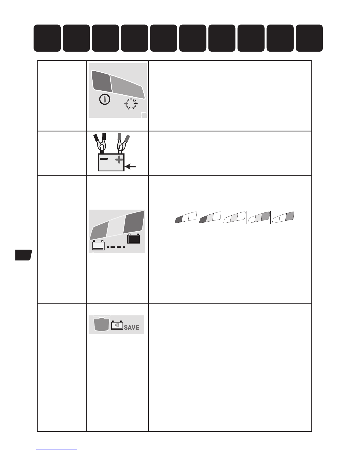
PT
3636
Proteção
REINICIAÇÃO BMS
2
1
O carregamento não irá continuar sem a interação do utilizador.
LED #2 POLARIDADE INVERTIDA: Acende-se quando as ligações da bateria
estão incorretas. O carregador é protegido eletronicamente para que não
ocorram danos e a saída permanece desativada até que as ligações sejam
corrigidas.
REINICIAÇÃO BMS: para baterias com sistema de gestão de bateria (battery
management system - BMS) que as protege contra o descarregamento
profundo. Desligue o carregador da alimentação elétrica. Aguarde que o LED
#1a/1b se apague. Volte a ligar à alimentação elétrica. É aplicado um impulso
especial de reiniciação do BMS durante até 5 segundos. O programa deve
continuar até ao PASSO 4.
ETAPA 1
Início Baixa
Tensão
≥ 0,5 V
V
Verificação da tensão da bateria - o OptiMate Lithium é ativado
automaticamente se a tensão da bateria ligada for, no mínimo, 0,5 Volt.
ETAPA 2
TESTE antes da
carga
ETAPA 3
Verificação da
temperatura
LED DE TESTE
#6 : VERDE
#7: AMARELO
#8 : VERMELHO
TEST
8
7
6
Os LED DE TESTE #6 / 7 / 8 indicam a condição da bateria antes do
carregamento. Consulte o quadro na página 2 para obter correspondência
entre a indicação do LED DE TESTE e a estimativa do estado em percentagem
de carga (SOC%).
8
7
6
90 100%603010%
13.3V 13.6V+ 13.13V13.00V12.80VV
8
7
7
6
0
0.5V
Durante o teste:
A OTIMIZAÇÃO do tempo de carregamento mínimo é definida conforme o
resultado do teste, e pode variar entre 10 minutos para uma bateria com um
estado de carga de 80% ou mais, até 120 minutos para uma bateria com um
estado de carga de 40% ou menos. A temperatura ambiente é medida para
determinar os parâmetros da tensão de carga.
AVISO DE TEMPERATURA BAIXA - LED #8 (vermelho) intermitente: A
temperatura medida no OptiMate Lithium é inferior a -20ºC (ou -4ºF),
inferior à zona de carregamento E descarregamento seguro para baterias
LiFePO
4
.
O carregamento inicia-se passados 10 segundos.
ETAPA 4
RECUPERAÇÃO
ULTRA BAIXA
TENSÃO
ETAPA 5
RECUPERAÇÃO
BAIXA TENSÃO
ETAPA 6
TESTE - células
danificadas
LED #3 : VERMELHO
3
IMPORTANTE: Se o aparelho entrar neste modo, leia a secção BATERIAS
NEGLIGENCIADAS MUITO DESCARREGADAS na página anterior.
O aparelho entra neste modo se a bateria estiver mais de 90% descarregada
/ a tensão for inferior a 12,8V (16V). Safe Tº: A corrente de carregamento é
ajustada automaticamente de acordo com a tensão e temperatura ambiente
medida durante o teste.
RECUPERAÇÃO COM TENSÃO MUITO BAIXA para baterias entre 0,6V
(0,75V) and 8,8V: A corrente começa com 125mA e aumenta até 325mA
dependendo do avanço do carregamento. Se a tensão não subir acima de
8,8V dentro de 2 horas, o carregamento é suspenso e o LED DE TESTE #8
(vermelho) fica intermitente, indicando que a bateria poderá ter sofrido danos
permanentes ou que é necessária uma avaliação profissional.
RECUPERAÇÃO COM TENSÃO MUITO BAIXA para baterias entre 8,9V and
12,8V: A corrente máxima é definida para 1,25A. Este modo controla se
existem comportamentos invulgares para determinar a aceitação de carga da
bateria. Uma bateria LiFePO
4
saudável avança para o modo de
CARREGAMENTO (CHARGE) no espaço de 4 horas, caso contrário, o
carregamento é suspenso e o LED DE TESTE #8 (vermelho) fica intermitente,
indicando que a bateria poderá ter sofrido danos permanentes ou que é
necessária uma avaliação profissional.
1091 2
3 4 5 6 7 8
Baixa Tensão
Início (0,5 V)
TESTE antes de
carregamento
Temperatura
verificação
Ultra BAIXA
RECUPERAÇÃO
DE TENSÃO
BAIXA TENSÃO
RECUPERAÇÃO /
monitorização
de células
OptiMate
manutenção
‘365’
TESTE após
CARREGAR
TESTE -
células
danificadas
equilíbrio
das células
CARREGAR
OTIMIZAÇÃO
Page 37
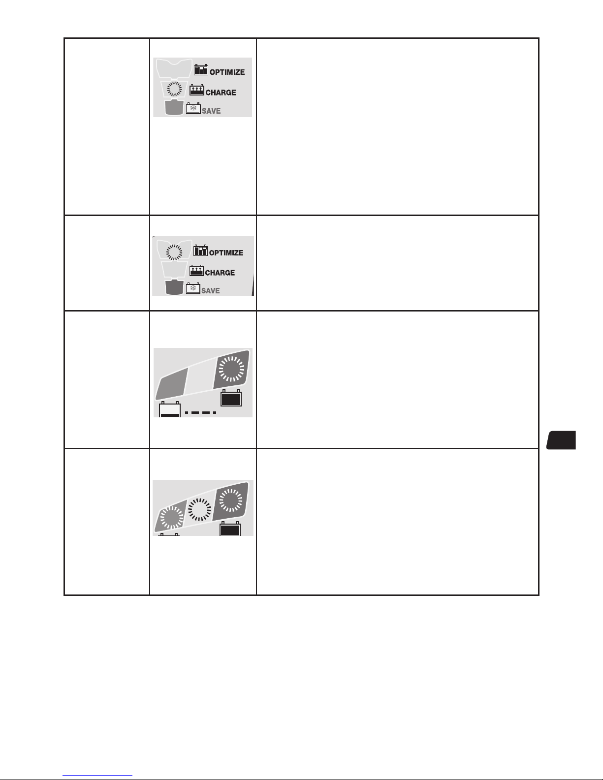
37PT37
ETAPA 7
CARGA
LED #4 : AMARELO
4
O programa SafeTº limita a corrente de carregamento se a temperatura medida
pelo OptiMate Lithium for abaixo dos 0ºC / 32ºF ou acima dos 45ºC / 113ºF. Se a
temperatura era inicialmente inferior a 0°C / 32°F, a corrente de carga é limitada a
325mA apenas durante a primeira hora, após a qual a bateria deverá ter
aumentado a temperatura interna dentro da zona de temperatura normal.
Dentro da zona de temperatura normal, o programa específico LiFePO
4
ampmatic™ determina automaticamente a taxa de corrente de carga mais
eficaz para a bateria ligada, de acordo com o seu estado de carga, o estado de
saúde e a capacidade de armazenamento elétrico (Ah). A corrente fornecida poderá
ser qualquer uma no intervalo de 1,25A a 9,5A.
Para baterias com uma capacidade de armazenamento elétrico (Ah) inferior a 10Ah
(8Ah), a corrente de carga é ajustada automaticamente para um valor mais baixo
com uma média igual à capacidade em Ah da bateria, por exemplo, uma bateria de
2,5Ah / 2500mAh recebe uma média de 2,5 Amps.
NOTA: Por motivos de segurança, existe um limite de tempo de carregamento total
de 24horas para os modos de RECUPERAÇÃO e de CARREGAMENTO.
ETAPA 8
OTIMIZAÇÃO
LED #5 : AMARELO
5
O modo de OTIMIZAÇÃO começa quando a tensão atinge os 14,4V pela primeira
vez durante o modo de CARREGAMENTO bruto.
O programa de controlo de corrente
ampmatic™ fornece agora impulsos de
corrente para equalizar as células individuais na bateria e otimiza o nível de carga
da bateria.
O carregamento deverá completar-se no tempo de carregamento mínimo
estabelecido no PASSO 3, porém, se a bateria necessitar de mais carga, o
programa prolonga o modo de OTIMIZAÇÃO até a um máximo de 2 horas.
ETAPA 9
TESTE após
o carga
LED #6 INTERMITENTE
TEST
6
TESTE após carregamento: O fornecimento de corrente à bateria é
interrompido durante 30minutos* para permitir que o programa determine a
capacidade de retenção de carga da bateria.
* CASO o carregamento se tenha iniciado no modo RECUPERAÇÃO (LED #3,
indicando uma bateria fortemente descarregada), ou o teste de retenção da
tensão seja prolongado para 12 horas para confirmar a integridade da bateria.
O resultado do TESTE (indicado nos LED #6, 7, 8) é ajustado em tempo real, de
acordo com a tensão medida da bateria. Consulte o quadro “AVISO ANTECIPADO
DE PROBLEMAS COM A BATERIA” na página 2 para obter correspondência entre a
indicação do LED de TESTE e a estimativa do estado em percentagem de carga
(SOC%).
Pode obter mais informações na secção “NOTAS SOBRE RESULTADOS DE TESTE”.
ETAPA 10
MANUTENÇÃO
inteligente
OPTIMATE
LED #6 / 7 / 8
LIGADO
8
7
6
No caso de baterias em bom
estado, o LED #6 (verde)
continuará aceso.
CARREGAMENTO DE MANUTENÇÃO: LED #6 / 7/ 8 acesos e estáveis,
dependendo da tensão final medida no final do PASSO 7.
O CICLO DE CARREGAMENTO DE MANUTENÇÃO consiste em períodos de
carregamento de 30 minutos seguidos alternadamente por períodos de “repouso”
de 30 minutos, durante os quais não há corrente de carga.
No período de carregamento de 30 minutos, só é aplicada corrente se a bateria
tiver perdido carga.
O CICLO DE RENOVAÇÃO DA BATERIA é realizado se o carregador detetar que a
bateria perdeu uma carga significativa. O programa volta ao modo OTIMIZAÇÃO
(LED #5) e, em seguida, avança para o teste de retenção de tensão e o ciclo de
carregamento de manutenção.
Leia a secção MANUTENÇÃO DE UMA BATERIA DE LÍTIO POR PERÍODOS
PROLONGADOS.
NOTAS SOBRE RESULTADOS DE TESTE:
1. Para qualquer resultado de teste que não seja #6 verde (ou #6 verde e #7 amarelo em conjunto se a bateria for do tipo STD com
tampas de enchimento), desligue a bateria do sistema eléctrico que esta suporta, e volte a ligar o OptiMate. Se, em seguida, for obtido
um resultado de teste melhor, significa que as perdas de energia se devem em parte a um problema eléctrico no sistema e não à
própria bateria. Se o mau resultado persistir, aconselha-se que leve a bateria a uma oficina de serviço profissional, que disponha de
equipamento profissional para uma investigação mais completa.
2. Se o LED #8 vermelho se acender sozinho ou juntamente com o LED #7 amarelo (ou apenas o LED amarelo no caso de uma bateria
selada), existe um problema significativo. Os LEDs vermelho/amarelo + vermelho significam que, após o carregamento, a tensão da
bateria não é mantida ou que, apesar das tentativas de recuperação, não foi possível recuperar a bateria. Isto pode ser devido a um
defeito na própria bateria, como por exemplo uma célula em curto-circuito ou sulfatação total, ou, no caso de uma bateria ainda ligada
ao sistema eléctrico que suporta, o LED #8 vermelho poderá indicar uma perda de corrente através do circuito eléctrico deteriorado, um
Page 38

PT
3838
interruptor ou um contacto degradado, ou acessórios que consomem corrente em circuito. A ligação de uma carga súbita enquanto o
carregador está ligado também pode provocar uma descida significativa da tensão da bateria.
3. BOM RESULTADO DE TESTE, mas a bateria não consegue fornecer energia eléctrica suficiente: um dano permanente na bateria
poderá estar a causar demasiado auto-descarregamento que não é detectado no período de teste de 12 horas. Desligue a bateria do
OptiMate. Após, pelo menos, 48 horas, volte a ligá-la e observe o resultado de TESTE durante o TESTE DE PRÉ-QUALIFICAÇÃO.
MANUTENÇÃO DE UMA BATERIA POR PERÍODOS PROLONGADOS: O OptiMate mantém uma bateria, cuja condição
básica seja boa, durante vários meses seguidos. Pelo menos uma vez em cada duas semanas, verifique se as ligações entre o
carregador e a bateria estão seguras, e, no caso das baterias com tampas de enchimento em cada célula, desligue a bateria do
carregador, verifique o nível do electrólito e, se necessário, encha as células (com água destilada, NÃO com ácido) e, em seguida,
volte a ligá-la. Quando estiver a manusear baterias ou se encontrar na sua proximidade, tenha sempre o cuidado de observar os
AVISOS DE SEGURANÇA acima.
MODO ECO DE POUPANÇA ENERGÉTICA QUANDO O CARREGADOR ESTÁ LIGADO À ALIMENTAÇÃO DE CORRENTE CA:
O conversor de corrente muda para o modo ECO quando o carregador não está ligado a uma bateria, resultando num consumo de
energia muito reduzido, inferior a 1,7W, equivalente ao consumo de 0,042 kWh por dia. Quando uma bateria é ligada ao carregador, o
consumo de energia depende da necessidade de corrente da bateria e do veículo/circuito electrónico ligado. Depois de a bateria ter sido
carregada e o carregador se encontrar no modo de carregamento de manutenção de longo prazo (para manter a bateria a 100% de
carga) o consumo total de energia é estimado em 0,060 kWh por dia ou menos.
GARANTIA LIMITADA
TecMate (International) NV, Sint-Truidensesteenweg 252, B-3300, Belgium, consente a presente garantia ao primeiro utilizador
deste produto, sem possibilidade de transferibilidade. TecMate (International) NV garante este carregador durante três anos a
partir da data de compra ao retalhista, contra os defeitos dos componentes ou de montagem. Se for o caso, o carregador será
reparado ou substituído à discrição do fabricante. O comprador deve enviar por sua própria conta, o aparelho assim como uma
prova de compra (veja "NOTA"), ao fabricante ou ao seu representante. Esta garantia limitada, torna-se nula se o aparelho for
utilizado ou manipulado de forma inadequada ou se tiver sido reparado por toda outra pessoa física ou moral que o fabricante
ou o seu representante. O fabricante não oferece nenhuma outra garantia que a presente, e excluí expressamente toda
garantia conta danos consequenciais.
ESTA É A ÚNICA GARANTIA EXPRESSAMENTE CONSENTIDA PELO FABRICANTE. ESTE NÃO ASSUME E NÃO AUTORIZA QUEM
QUER QUE SEJA A ASSUMIR OU ESTABELECER TODA OUTRA OBRIGAÇÃO LIGADA A ESTE PRODUTO, OUTRA QUE ESTA
GARANTIA LIMITADA EXPRESSAMENTE CONSENTIDA. SUAS DIREITAS ESTATUTÁRIAS NÃO SÃO AFETADAS.
NOTA: Veja www.tecmate.com/warranty o contatem warranty@tecmate.com
Pode-se encontrar mais informação sobre os produtos de TecMate em www.tecmate.com.
GARANTIA no Canadá, EUA, América Central e América do Sul:
A TecMate North America, Oakville, ON, Canadá, sociedade filial totalmente detida pela TecMate International, assume a
responsabilidade pela garantia do produto nestas regiões.
Pode-se encontrar mais informação sobre os produtos de TecMate em www.tecmate.com.
Page 39

CZ
39
AUTOMATICKÁ DIAGNOSTICKÁ NABÍJEČKA PRO 12,8V BATERIE LIFEPO4
(LITHIUM-ŽELEZO-FOSFÁT) AŽ DO 100 AH:
DŮLEŽITÉ: PŘED POUŽITÍM NABÍJEČKY SI PŘEČTĚTE NÁSLEDUJÍCÍ POKYNY
Toto zařízení není určeno pro používání osobami (včetně dětí) se sníženými fyzickými, senzorickými
nebo duševními schopnostmi nebo s nedostatkem zkušeností a znalostí, pokud nepracují pod dozorem
nebo pokud od osoby zodpovědné za jejich bezpečnost neobdržely pokyny týkající se používání
zařízení. Děti by měly být pod dozorem, aby si nemohly s tímto zařízením hrát.
Pokud je vstupní kabel poškozen, nechte jej neprodleně vyměnit u výrobce, jeho autorizovaného
servisního zástupce nebo v kompetentní dílně, aby nevzniklo nebezpečí. Při používání i skladování
chraňte nabíječku před kyselinou, kyselými výpary a vlhkostí. Na poškození vzniklé korozí, oxidací nebo
vnitřním elektrickým zkratem se záruka nevztahuje. Nabíječku udržujte během nabíjení baterie v dostatečné
vzdálenosti, aby nedošlo ke znečištění nebo styku s kyselinou nebo kyselými výpary. Pokud používáte
nabíječku ve vodorovné poloze, položte ji na tvrdý, hladký povrch, ale NIKDY na plast, textil nebo kůži. Použijte
připravené otvory na spodní straně krytu k upevnění nabíječky k jakémukoli vhodnému, pevnému svislému
povrchu.
VYSTAVENÍ TEKUTINÁM: Nabíječka je navržena tak, aby odolala styku s kapalinami náhodně rozlitými nebo
rozstříknutými na pouzdro shora nebo mírnému dešti. Nedoporučuje se ponechávat nabíječku dlouhodobě
vystavenou dešti, což by rovněž mělo za následek zkrácení životnosti. Na poruchy nabíječky v důsledku
oxidace způsobené případným proniknutím tekutiny k elektronickým součástkám, svorkám nebo zástrčkám,
se záruka nevztahuje.
ZANEDBANÉ, SILNĚ VYBITÉ BATERIE: Věnujte zvláštní pozornost následující informaci o baterii LiFePO4 Pokud necháte
baterii dlouhou dobu silně vybitou, může se trvale poškodit jeden nebo více článků.
Takové baterie se mohou při nabíjení nadměrně zahřívat. Během ŠETRNÉHO režimu program omezuje nabíjecí proud,
pokud je napětí pod jmenovitou hodnotou (12,8 V) a program by měl odhalit zjevné poškození článků a automaticky
pozastavit nabíjení, ale čím vyšší je počet paralelně zapojených článků, tím obtížnější je detekovat vadný článek. Např. 5Ah
baterie má obvykle 4 řady propojených sad 2 paralelních článků (konfigurace 4S2P – celkem 8 článků), 10Ah baterie má 4
řady propojených sad 4 paralelních článků (konfigurace 4S4P – celkem 16 článků).
VŽDY monitorujte teplotu baterie během první hodiny a potom dále každou hodinu. Kdykoli je baterie příliš horká na to,
abyste se jí mohli dotknout, nebo zaznamenáte-li nezvyklé příznaky, OKAMŽITĚ
PŘIPOJENÍ NABÍJEČKY K BATERII
1. Před připojením nebo odpojením stejnosměrného proudu / připojení baterie odpojte zdroj střídavého proudu.
2. Pokud nabíjíte baterii ve vozidle pomocí svorek baterie ujistěte se před připojením, že je možné svorky baterie bezpečně umístit
tak, aby nenarušily okolní vedení, kovové potrubí nebo rám. Připojení provádějte v tomto pořadí: Nejprve připojte pól baterie, který
není připojen k rámu (obvykle kladný), pak připojte další svorku baterie (obvykle zápornou), která je připojena k rámu tak, aby
nezasahovala do vedení baterie nebo paliva. Odpojujte vždy v opačném pořadí.
3. Pokud nabíjíte baterii svorkami mimo vozidlo, umístěte ji v dobře větraném prostoru. Připojte nabíječku k baterii: ČERVENOU svorku
ke KLADNÉMU (POS, P nebo +) pólu a ČERNOU svorku k ZÁPORNÉMU (NEG, N nebo -) pólu. Dbejte na to, aby byla připojení pevná
a bezpečná. Dobrý kontakt je důležitý.
PŘECHOD K NABÍJENÍ
DOBA NABÍJENÍ: Na dobu nabíjení má vliv okolní teplota. Pokud nabíječka OptiMate Lithium naměří teplotu nižší než 0 °C nebo vyšší
než 45 °C, program safeT omezí nabíjecí proud. Při běžných teplotách program ampmatic™ LiFePO
4
automaticky určí nejúčinnější
hodnotu nabíjecího proudu pro připojenou baterii podle stavu nabití, fyzického stavu a podle kapacity baterie (Ah). Dodávaný proud může
být v rozmezí od 1,25 A do 5 A.
Doba nabíjení zcela vybité, ale jinak nepoškozené baterie:
Pro baterie se jmenovitou kapacitou od 2,5 Ah do 5 Ah: 60 až 120 minut pro přechod k testu udržení napětí.
Pro baterie se jmenovitou kapacitou vyšší než 5 Ah: přibližně 25 % jmenovité hodnoty Ah baterie, takže u 50Ah baterie by přechod k
testu udržení napětí neměl trvat déle než 5 hodin.
V případě silně vybitých baterií to může trvat déle.
Page 40

CZ
40
Ochrana
Reset BMS
2
1
Nabíječka nebude pokračovat v činnosti bez akce
uživatele.
LED č. 2 – OBRÁCENÁ POLARITA: Svítí při nesprávném připojení
baterie. Nabíječka je elektronicky chráněna, takže nedojde k jejímu poškození.
Výstup se obnoví až po správném připojení.
RESET BMS: pro baterie se systémem správy baterií (BMS), který chrání před
silným vybitím. Odpojte nabíječku od hlavního přívodu energie. Počkejte, dokud
nezhasne LED č. 1a/1b. Připojte nabíječku zpět k hlavnímu přívodu energie. Po
dobu až 5 sekund je přenášen speciální resetovací puls BMS. Program by měl
pokračovat na KROK 4.
KROK 1
Nízkonapěťový
start
≥ 0.5V
V
Kontrola napětí baterie – nabíječka OptiMate Lithium se
automaticky aktivuje když je napětí připojené baterie nejméně
0,5 V.
KROK 2
TEST
před
nabitím
KROK 3
Kontrola
teploty
TESTOVACÍ LED
6: ZELENÁ
7: ŽLUTÁ
8: ČERVENÁ
TEST
8
7
6
TESTOVACÍ LED č. 6/7/8 označují stav baterie před nabitím. V tabulce na str.
2 je uveden vztah mezi LED indikací TESTU a odhadovaným stavem nabití v
procentech (SOC%).
Během testu:
OPTIMALIZACE: Podle výsledku testu se nastaví minimální čas nabíjení, od 10
minut pro baterii nabitou na 80 % a více, až po 120 minut pro baterii nabitou na
40 % a méně.
K určení parametrů nabíjecího napětí je změřena okolní teplota.
UPOZORNĚNÍ NA NÍZKOU TEPLOTU – bliká LED č. 8 (červená): Teplota měřená na
nabíječce OptiMate Lithium je nižší než -20 stupňů Celsia, pod zónou
bezpečného nabíjení a vybíjení pro baterie LiFePO
4
.
Nabíjení bude zahájeno za 10 sekund.
8
7
6
90 100%603010%
13.3V 13.6V+ 13.13V13.00V12.80VV
8
7
7
6
0
0.5V
KROK 4
ULTRA
NÍZKONAPĚŤOVÝ
ŠETRNÝ REŽIM
KROK 5
NÍZKONAPĚŤOVÝ
ŠETRNÝ REŽIM
STEP 6
TEST
– poškození
článků
LED č. 3: ČERVENÁ
3
DŮLEŽITÉ: Pokud se aktivujte tento režim, přečtěte si část ZANEDBANÉ SILNĚ
VYBITÉ BATERIE na předchozí stránce.
Tento režim se aktivuje, když je baterie vybitá z více než 90 % / napětí je nižší
než 12,8V. safeT: Nabíjecí proud se během testu automaticky nastavuje
podle napětí a okolní teploty.
ZÁCHRANA PŘI VELMI NÍZKÉM NAPĚTÍ pro baterie mezi 0,6 V (0,75 V) a
8,8 V:
Proud začíná na 125 mA a v závislosti na průběhu nabíjení se zvýší na 325
mA. Pokud se napětí během 2 hodin nezvýší nad 8,8 V, bude nabíjení
pozastaveno a TESTOVACÍ LED č. 8 (červená) začne blikat a indikovat tak, že
baterie může být trvale poškozená, nebo že je potřeba profesionální posouzení.
ZÁCHRANA PŘI NÍZKÉM NAPĚTÍ pro baterie mezi 8,9 V a 12,8 V: Maximální
proud je nastaven na 1,25 A. Nabíjení baterie je monitorováno, zda nevykazuje
neobvyklé chování. Baterie LiFePO4 v dobré kondici během 4 hodin přejde k
nabíjení, jinak bude nabíjení pozastaveno a TESTOVACÍ LED č. 8 (červená)
začne blikat a indikovat tak, že baterie může být trvale poškozená, nebo že je
potřeba provést odborné posouzení stavu.
1091 2
3 4 5 6 7 8
Nízkonapěťový
start (0,5V)
TEST před
nabitím
Teploty
Kontrola
ÚSPORNÝ REŽIM
PŘI ULTRA
NÍZKÉM NAPĚTÍ
ÚSPORNÝ REŽIM
PŘI NÍZKÉM
NAPĚTÍ /
sledování článků
Údržba
nabíječky
OptiMate ‘365’
TEST po
NABITÍ
TEST –
poškození
článků
NABÍJENÍ
svyvažováním
článků
OPTIMALIZACE
Page 41

CZ
41
KROK 7
NABÍJENÍ
LED č. 4: ŽLUTÁ
4
Pokud nabíječka OptiMate Lithium naměří teplotu nižší než 0 °C nebo vyšší
než 45 °C, program safeT omezí nabíjecí proud. Pokud byla teplota původně
nižší než 0 °C, nabíjecí proud je během první hodiny omezen pouze na 325 mA
a po této době by se vnitřní teplota baterie měla zvýšit na běžnou teplotu.
Při běžných teplotách program ampmatic™ LiFePO
4
automaticky určí
nejúčinnější hodnotu nabíjecího proudu pro připojenou baterii podle stavu
nabití, fyzického stavu a podle kapacity baterie (Ah). Dodávaný proud může být
v rozmezí od 1,25 A do 9,5 A.
U baterií s kapacitou (Ah) nižší než 10 Ah (8 Ah) je nabíjecí proud automaticky
snížen na průměrnou kapacitu baterie Ah, tj. 2,5Ah/2500mAh baterie bude
přijímat přibližně 2,5A.
POZNÁMKA: Z bezpečnostních důvodů je pro režimy ZÁCHRANA a NABÍJENÍ
stanoven časový limit 24 hodin.
KROK 8
OPTIMALIZACE
LED č. 5: ŽLUTÁ
5
Režim OPTIMALIZACE začíná, když napětí při hromadném režimu NABÍJENÍ
poprvé dosáhne 14,4 V (18 V).
Program pro řízení proudu ampmatic™ nyní dodává proudové pulzy, aby
vyrovnal jednotlivé články baterie a optimalizoval úroveň nabití.
Nabíjení by mělo během KROKU 3 proběhnout v co nejkratším čase, ale pokud
baterie vyžaduje další nabíjení, program prodlouží režim OPTIMALIZACE až na
maximálně 2 hodiny.
KROK 9
TEST po
nabití
LED č. 6 BLIKÁ
TEST
6
TEST po nabití: Dodávka proudu do baterie je přerušena na 30 minut*,
aby program mohl určit schopnost baterie udržet nabití.
* POKUD nabíjení začalo v režimu ZÁCHRANA (LED č. 3, indikující silně vybitou
baterii) nebo je test udržení napětí prodloužen na 12 hodin, aby byl potvrzen
dobrý stav baterie.
Výsledek TESTU (indikovaný LED č. 6, 7, 8) je upravován v reálném čase podle
změřeného napětí baterie. V tabulce „VČASNÉ UPOZORNĚNÍ NA POTÍŽE S
BATERIÍ“ na str. 2 je uveden vztah mezi LED indikací TESTU a odhadovaným
stavem nabití v procentech (SOC%).
Další informace najdete v části „POZNÁMKY K VÝSLEDKŮM TESTU“.
KROK 10
OptiMATE
inteligentní
ÚDRŽBA
LED č. 6 / 7 / 8 SVÍTÍ
TEST
8
7
6
V případě baterií v dobrém
stavu zůstane LED č. 6
(zelená) svítit
UDRŽOVACÍ NABÍJENÍ: LED č. 6 / 7 / 8 svítí podle
konečného napětí měřeného při ukončení KROKU 7.
CYKLUS ÚDRŽBY NABITÍ se skládá z 30minutových intervalů nabíjení, po
kterých následují 30minutové „klidové“ intervaly, kdy se baterie nenabíjí.
V průběhu 30minutových nabíjecích cyklů je proud dodáván pouze v případě,
pokud poklesne napětí baterie.
Při silném poklesu nabití baterie je proveden CYKLUS OBNOVENÍ BATERIE.
Program se vrátí do režimu OPTIMALIZACE (LED č. 5) a poté přejde k testu
udržení napětí a k cyklu udržovacího nabíjení.
Přečtěte si část ÚDRŽBA LITHIOVÉ BATERIE V DELŠÍM OBDOBÍ.
POZNÁMKY K VÝSLEDKŮM TESTU:
1. Pokud je výsledkem testu cokoli jiného než zelená LED dioda č. 6, odpojte baterii od elektrického systému, který ji napájí, a znovu
zapojte OptiMate. Pokud je nyní výsledek testu lepší, ukazuje to, že ztráty energie jsou zčásti zapříčiněny problémem v elektrickém
systému a ne v samotné baterii.
2. Pokud svítí samostatně červená LED č. 8 nebo společně žlutá LED č. 7 a červená LED č. 8 (nebo svítí samostatně žlutá LED u
uzavřené baterie), znamená to závažný problém. Červená / žlutá a červená LED znamená, že po nabití napětí baterie klesá, nebo se přes
všechny pokusy o oživení nepodařilo baterii oživit. Může to být způsobeno závadou baterie, například zkratovaným článkem, nebo v
případě, kdy je baterie stále připojená k elektrickému systému, který podporuje, to může signalizovat ztrátu proudu narušeným
zapojením nebo zničeným spínačem nebo kontaktem, nebo příslušenstvím v obvodu, které spotřebovává proud.
Náhlé zatížení ve chvíli, kdy je nabíječka připojená, může rovněž způsobit znatelný pokles napětí baterie.
3. Bliká TESTOVACÍ LED č. 8 (červená) – nabíjení je pozastaveno. Při testu udržení napětí je během prvních 30 minut napětí sníženo pod
12,8 V, což značí, že baterie mohla utrpět trvalé poškození a je nutné provést odborné posouzení stavu. Další informace o produktech
TESTOVÁNÍ nebo MONITOROVÁNÍ OptiMate najdete na adrese www.optimate1.com.
Page 42

CZ
ÚDRŽBA LITHIOVÉ BATERIE V DELŠÍM OBDOBÍ: Baterie LiFePO4 může být k nabíječce OptiMate Lithium připojena libovolně
dlouhou dobu. Program údržby nabíječky OptiMate Lithium je plně automatický. Nepřetržitě monitoruje napětí baterie a dodává proud
jen tehdy, když detekuje, že u baterie pokleslo napětí (pravděpodobně z důvodu připojeného vozidla nebo jiného obvodu nebo z důvodu
samovybíjení). Program údržby nabíječky OptiMate Lithium zaručuje, že baterie bude stále plně nebo téměř plně nabitá, ale nikdy
nebude přebitá.
EKO ÚSPORNÝ REŽIM PŘI PŘIPOJENÍ NABÍJEČKY KE ZDROJI STŘÍDAVÉHO PROUDU:
Když není nabíječka připojena k baterii, měnič se přepne do režimu EKO. To zaručuje velmi nízkou spotřebu, méně než 0,5 W, což
představuje spotřebu 0,012 kWh denně. Když je k nabíječce připojená baterie, závisí spotřeba na skutečné dodávce do baterie a na
tom, zda je připojena k vozidlu / elektronické soustavě obvodů. Po nabití baterie, kdy je nabíječka v režimu dlouhodobé údržby
baterie (udržuje baterii 100% nabitou), se celková spotřeba odhaduje na 0,024 kWh denně nebo méně.
OMEZEN. Z.RUKA
Společnost TecMate (International) SA, Sint-Truidensesteenweg 252, B-3300 Tienen, Belgie, poskytuje tuto omezenou z.ruku
původn.mu kupci tohoto výrobku. Tato omezen. z.ruka je nepřevoditeln.. Společnost TechMate (International) poskytuje z.ruku na
vady materi.lu a výrobn. vady t.to nab.ječky bateri. na dobu tř. let od data n.kupu u prodejce. Pokud se vyskytne z.vada, výrobce
posoud., zda jednotku oprav. nebo vyměn.. Kupuj.c. je povinen na vlastn. n.klady zaslat jednotku spolu s dokladem o koupi (viz
POZN.MKA) výrobci nebo jeho autorizovan.mu z.stupci. Tato omezen. z.ruka zanik., pokud se výrobek nepouž.v. v souladu s n.
vodem, nakl.d. se s n.m nešetrně nebo byla provedena oprava jinde než v tov.rně nebo u autorizovan.ho z.stupce. Výrobce
neposkytuje ž.dnou jinou z.ruku, pouze tuto omezenou z.ruku a výslovně vylučuje jakoukoli nevyj.dřenou z.ruku včetně z.ruky na n.
sledn. poškozen..
JEDN. SE O JEDINOU UZNANOU OMEZENOU Z.RUKU A V.ROBCE NEPŘEB.R. ANI NEPOVĚŘUJE Ž.DNOU JINOU OSOBU, ABY PŘEVZALA
NEBO UZAV.RALA VE VZTAHU K V.ROBKU JIN. Z.VAZKY, NEŽ JE TATO OMEZEN. Z.RUKA. VAŠE Z.KONN. PR.VA T.M OVLIVNĚNA
NEJSOU.
POZN.MKA: Podrobnosti naleznete na www.tecmate.com/warranty
42
Page 43

PRODUCT INFORMATION
Certification / Conformity
Holder: TecMate (International ) S.A. , B-3300 Tienen, Belgium
Issued by: TUV SUD Product Service GmbH, DE (Safety and EMC)
Safety (CE-LVD) : Low voltage directive 2014/35/EU; EN 60335-2-29:2004/A2:2010;
EN 60335-1:2012/A11:2014; EN 62233:2008
Safety (NRTL) : UL 1236:2015; CAN/CSA C22.2 no. 107.2-01 (R2011)
Safety (SAA) : AS/NZS 60335.2.29:2004 Inc A1-2; AS/NZS 60335.1.2011 Inc A1
EMC (CE) : EMC Directive 2014/30/EU; EN55014-1 2006/A2:2011; EN55014-2
1997/A2:2008; EN61000-3-2:2014; EN61000-3-3:2013
EMC (NRTL) : FCC CFR Title 47 Part 15 Subpart B
Efficiency - BC
mark
(California
Energy Commision)
CEC-400-2012-011-CMF; 10 CFR Section 430.23 (aa) Appendix Y to
Subpart B of Part 430.
Tests by: Mantek International Canada Inc, Oakville ON, Canada.
Listed models: TM29x
Energy usage: Not charging: P < 0.5W Long term maintenance: P < 0.5W ( < 0.012
kWh / day, < 4.4 kWh / year )
Mechanical
IP rating IP54
t° operating range -20°C <-> 40°C / -4°F <-> 104°F
Weight (packed) 0.8kg (1.3kg) / 1.76lbs (2.87lbs)
Size without cable 220 x 70 x 90mm / 9.45" x 2.76" x 3.54"
Cable Length Input: 180cm / 71" Output: 191cm / 75"
Wall mount 4 mount positions
Accessories O-01 Weatherproof battery cable; O-04 battery Clips.
Standard SAE connectors
Electrical (additional)
Reverse drain Id < 0.5mA
Max input rating 90 - 264Vac 47-63Hz
Output volt range 0.5V - 14.4V @ 5A
Protection Input AC fuse: 3A 250V (non accessible)
Protection output AUTOMATIC: reverse polarity; no output if no battery is connected;
limited output current (1A max).
Origin
Design copyright
& trademark
TecMate (International) S.A., B-3300 Tienen, Belgium
www.tecmate.com
Page 44

4
CZ
PT
optimate1.com
4x
4.5mm / 3/16”
L ≥ 25mm / 1”
OptiMate HOOK
TS-252
OptiMate CABLE Extenders
1.8m / 6ft max.
+ O-03 3.6m / 12ft
STD
+ O-13 6.6m / 21ft
 Loading...