

Page 1
InstructIons for use
IMPORTANT: Read completely
before charging
Automatic charger for 12V lead/acid batteries
Chargeur automatique pour batteries 12V plomb-acide
Cargador automático para baterías
12V plomo-ácido
Carregador automático para baterias
de 12V chumbo/ácido
Mode d’eMploI
IMPORTANT: à lire avant d’utiliser l’appareil
Modo de eMpleo
IMPORTANTE: a leer antes de utilizar el aparato
Instruções de utIlIzação
IMPORTANTE: Ler antes de utilizar.
Page 2
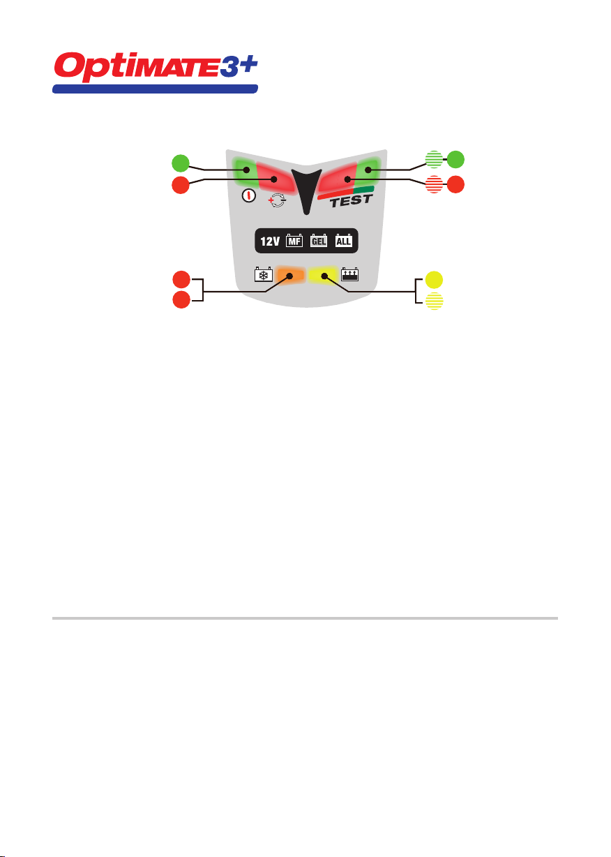
QUICK GUIDE – LED INFORMATION PANEL
3.1
3.2
4.1
4.2
6 6
5 5
2
1
TEST MAINTAIN
CHARGE
VERIFY
DESULFATE
ACTIVATE
Full details on any LED or step can be found in the manual under the same #
1. LED #1 - Power on. This LED confirms AC power supply to the charger.
2. LED #2 indicates inverse polarity - wrong output connections. Swap around to activate output.
3. Circuit activation and recovery of deep-discharged, neglected batteries
3.1 ACTIVATION - If the battery voltage is above 2V, LED #3 lights briefly to confirm circuit activation.
For most batteries LED #3 goes out immediately and charge LED #4 comes on.
3.2 RECOVERY - For neglected or very flat batteries, LED #3 remains on and indicates steadily.
If step 3 has not concluded after 2 hours, step 4 engages automatically.
4. Charge and charge verification
4.1 CHARGE: A steady LED #4 indicates the bulk charge stage.
4.2 VERIFICATION: LED #4 flashes while the circuit verifies battery charge level.
If the battery requires further charging the programme reverts to CHARGE. Multiple reversions may occur.
These reversions will cause LED #4 to alternate between steady and flashing, irregularly.
When LED #4 has flashed continuously for 30 minutes, step 5 engages and a voltage retention test starts.
5. 6. Voltage retention tests alternating half-hourly with battery maintenance
5. For a good battery LED #5 flashes throughout the 30 minute test. NO CHARGE CURRENT.
6. If the battery voltage falls below 12,4V during the test LED #6 (red) willcome on & indicate steadily.
Read § 6 in the main manual if LED #6 indicate in this period.
Maintenance - float charge at a safe voltage limit to counter self-discharge.
Each test period is followed by a 30 minute maintenance charge period. Whichever LED (#5 flashing or #6 steady)
was indicating at the end of the TEST now indicates steadily. The battery can draw current as required to support
small loads & counter self-discharge.
Maintenance and voltage retention test periods continue alternating half-hourly until the battery is disconnected.
The test result is updated during each subsequent test.
LIMITED WARRANTY
TecMate North America, 22–1100 Invicta Drive, Oakville, Ontario, Canada L6H 2K9 makes this limited warranty
to the original purchaser at retail of this product. This limited warranty is not transferable. TecMate North America
warrants this battery charger for two years from date of purchase at retail against defective material or workmanship.
If such should occur the unit will be repaired or replaced at the option of the manufacturer. It is the obligation of
the purchaser to forward the unit together with proof of purchase, transportation or mailing costs prepaid, to the
manufacturer or its authorized representative. This limited warranty is void if the product is misused, subjected to
careless handling, or repaired by anyone other than the factory or its authorized representative. The manufacturer
makes no warranty other than this limited warranty and expressly excludes any implied warranty including any
warranty for consequential damages.
THIS IS THE ONLY EXPRESS LIMITED WARRANTY AND THE MANUFACTURER NEITHER ASSUMES NOR AUTHORIZES
ANYONE TO ASSUME OR MAKE ANY OTHER OBLIGATION TOWARDS THE PRODUCT OTHER THAN THIS EXPRESS
LIMITED WARRANTY. YOUR STATUTORY RIGHTS ARE NOT AFFECTED.
Page 3

AUTOMATIC CHARGER FOR 12V LEAD/ACID BATTERIES.
Recommended for batteries of from 2 to 35Ah capacity. Do not use for NiCd, NiMH, Li-Ion or
non-rechargeable batteries. Input: 110-120V~ 0.075A. Output: 0.6A 9W (max).
IMPORTANT: READ THE FOLLOWING FULL INSTRUCTIONS FOR USE BEFORE USING THE CHARGER.
SAFETY WARNING AND NOTES:
Disconnect AC power supply before making or breaking DC/battery connections. Battery acid is highly corrosive. Wear
protective clothing and eyewear and avoid contact. In case of accidental contact, wash immediately with soap and
water. Check that the battery posts are not loose; if so, have the battery professionally assessed. If the battery posts
are corroded, clean with a copper wire brush; if greasy or dirty clean with a rag damped in detergent. Use the charger
only if the input and output leads and connectors are in good, undamaged condition. If the input cable is damaged,
it is essential to have it replaced without delay by the manufacturer, his authorised service agent or a qualified
workshop, to avoid danger. Protect your charger from acid and acid fumes and from damp and humid conditions both
during use and in storage. Damage resulting from corrosion, oxidation or internal electrical short-circuiting is not
covered by warranty. Distance the charger from the battery during charging to avoid contamination by or exposure
to acid or acidic vapours. If using it in the horizontal orientation, place the charger on a hard, flat surface, but NOT on
plastic, textile or leather. Otherwise use the fixing holes provided in the enclosure base to attach the charger to any
convenient, sound vertical surface.
EXPOSURE TO LIQUIDS: When placed on a horizontal flat surface this charger is designed to withstand exposure
to liquids accidentally spilled or splashed onto the casing from above, or to light rainfall. Do not allow liquid to
accumulate below or around the base of the charger. Prolonged exposure to falling rain is inadvisable and longer
service life will be obtained by minimizing such exposure. Failure of the charger due to oxidation resulting from the
eventual penetration of liquid into the electronic components is not covered by warranty. Never expose connectors or
plugs to rain or snow.
BATTERY CONNECTIONS: 2 sets of interchangeable connection sets are supplied to connect the battery to the
charger. One has crocodile clamps for charging the battery off-vehicle, the other has metal eyelets intended for
permanent connection to the battery posts, and a resealable rubber protective cap on the 2-pole connector at its
other extremity. When fixed permanently to the vehicle’s battery, this connection set allows easy and sure connection
of the charger to maintain the battery on-vehicle. The resealable rubber cap should be closed whenever the charger
is disconnected and/or the vehicle is in use so as to protect the 2-pole connector from dirt and damp. Consult a
professional service agent for assistance in attaching the metal eyelets to the battery posts. Distance the polarized
two-pole connector (for connection to the charger) as far as possible from the battery and secure it so that it
cannot foul any moving part of the vehicle or be pinched or damaged by sharp edges. The in-line fuse in the eyelets
connection set protects the battery against such accidental shorting across positive and negative conductors. Replace
any burnt fuse only with a similar new fuse of identical type and 7.5A rating.
IMPORTANT NOTES:
1. When charging a car battery, or if using the battery clamps, first disconnect and remove the battery from the
vehicle and place it in a well ventilated area.
2. If the battery is deeply discharged (and possibly sulfated), it is essential to disconnect the battery from the
vehicle before connecting the charger for a recovery attempt. The charger’s special recovery mode cannot
engage if it senses that the battery is still connected to a vehicle wiring circuit which effectively offers a lower
electrical resistance than the battery on its own. However, if the deep-discharged battery is not removed for
recovery, neither battery nor vehicle electronics will be damaged.
3. If nonetheless you intend to connect the charger to an automotive battery using the battery clips connection
set without first disconnecting and removing the battery, connect first to the battery terminal not connected to
the chassis, then the other battery clip to the chassis well away from the battery and fuel line. Do this before
connecting to the AC input. Always disconnect in reverse sequence.
Batteries emit EXPLOSIVE GASES - prevent flame or sparks near batteries.
Page 4

4
USING THE OPTIMATE™3+
The clauses below are numbered the same as the quick guide on the inside front cover.
1. and 2. Connections and input power
Connect the charger to the battery: RED clamp to POSITIVE (POS, P, +) terminal and BLACK clamp to NEGATIVE (NEG,
N,–) terminal. Now you are ready to start:
1. Connect the charger to a mains supply socket providing AC supply of 110 to 120V. The “POWER ON” LED #1
should illuminate. If not, check your AC supply and the connection to it.
2. If the INVERSE POLARITY LED #2 indicates, the battery connections are incorrect. The charger is electronically
protected so no damage will result, and the output will be disabled automatically. Disconnect the AC input,
swap the battery connections around, then restore the AC input power.
3. Circuit activation and recovery of deep-discharged, neglected batteries
For safety reasons, the OptiMate™ output will only switch on if a battery retaining at least 2V is correctly connected to
it and to a live 110-120V input. If these conditions are not met, only the POWER ON LED #1 will light on the LED panel.
3.1 Immediately the output circuit is activated, the orange DESULFATE LED #3 comes on very briefly while the
3.2 If the battery is extremely flat (deep-discharged or sulfated), the DESULFATE LED will continue to indicate
NOTE: A battery left deep-discharged for an extended period may develop permanent damage in one or more cells.
Such batteries may heat up excessively during charging. Stop charging any battery immediately if it is uncomfortably
hot to touch.
4. Charge and charge verification
4.1 The BULK CHARGE stage (steady LED #4) delivers a constant current of about 0.6 Amps into the battery. This
4.2 CHARGE VERIFICATION (flashing LED #4): The charging voltage is now limited at 13.6V during 30 minutes
NOTE Some sealed “MF” or “AGM” batteries that have been neglected may cause the programme to advance to the
CHARGE VERIFICATION stage (4.2) without proceeding through the bulk CHARGE stage (§ 4.1). The built-in diagnostics
will detect and correct this anomaly. The circuit will oscillate between bulk charge and verification as described in §
4.2.
5. and 6.
Voltage retention tests alternating half-hourly with battery maintenance
The first VOLTAGE RETENTION TEST period of 30 minutes follows § 4.2, thereafter a 30 minute MAINTENANCE period.
These 30 minute TEST and MAINTENANCE periods then alternate for as long as the battery remains connected.
Delivery of current to the battery is interrupted for 30 minutes during voltage retention test periods to allow the
battery to rest (thereby minimizing loss of water from the electrolyte) and to allow the circuit to monitor the battery’s
voltage decline to determine its ability to retain charge and deliver power.
™
OptiMate
can, the yellow CHARGE LED #4 will almost immediately replace the DESULFATE LED.
for up to 2 hours while a special high voltage is applied to force a very small fixed current into the battery in
a recovery attempt. The charge voltage is limited at a maximum 20V while the circuit attempts to deliver a
current of 200mA into the battery. Ths can continue for up to 2 hours maximum, or until the moment when the
automatic circuit judges that the battery can accept the normal charging programme. At this moment or in any
case after the maximum time limit of 2 hours has elapsed, the CHARGE mode (§ 4) will engage.
will cause the charging voltage to increase gradually. When it reaches 14.3V, the OptiMate
absorption and CHARGE VERIFICATION stage.
whilst the battery’s charge level is verified. If the battery requires further charging the programme will revert to
the main CHARGING stage (§ 4.1) and yellow LED #4 will indicate steadily again. When the rising voltage again
signals that the battery is approaching full charge the circuit reverts to VERIFICATION and LED #4 resumes
flashing. These reversions may occur as many times as is necessary to reduce the battery’s current demand
below 200mA at 13.6V (which is consistent with a battery that has accepted as much charge as its basic
condition allows). As soon as the circuit has verified that the charge is adequate (signaled by LED #4 having
flashed continuously and consistently for a full 30 minutes), the voltage retention test (see § 5) automatically
follows.
checks whether the battery can be charged effectively by the normal multi-stage programme. If it
™
will start the
Page 5

5
5. For batteries with a good state of health the green LED #5 should flash at the start of the test period and
continue to flash for the full 30 minutes until the next 30 minute maintenance period commences, when the
LED indication reverts to steady.
6. If the battery remains in circuit with the vehicle’s electrical system, and accessories or lights impose an
electrical load on the battery, the green LED may give way to a steady red LED indication.
Remove the battery from the vehicle and reconnect the OptiMate. The charge programme will in due course
again arrive at a voltage retention test result. If the LED indication is again red, read the following note.
NOTE ON RED LED INDICATION #6: If the above test on a battery removed from the vehicle results in a red LED
indication, you are advised to take the battery to a professional service workshop equipped with a BatteryMate
motorcycle battery tester-charger ( www.batterymate.com ) or a TestMate
™
digital battery tester
™
(www.testmate.com), for a more thorough investigation. The red LED means that after being charged the battery’s
voltage is not being sustained or that despite recovery attempts the battery was irrecoverable. This may be due to a
defect in the battery itself, such as a short-circuited cell or total sulphation, or, in the case of a battery still connected
to the vehicle’s wiring system, the red LED #6 may be signalling a loss of current through deteriorated wiring or a
degraded switch or contact, or in-circuit current-consuming accessories. A sudden load such as the headlights being
switched on while the charger is connected can also cause the battery voltage to dip significantly. Always remove the
battery from the vehicle, reconnect the OptiMate
FINAL NOTE ON THE VOLTAGE RETENTION TEST: This test is a strongly indicative but not necessarily a conclusive
test of battery condition, which can be more precisely established by using a TestMate
™
and allow it to proceed through its programme once more.
™
mini which tests 12V batteries
on the vehicle during cranking, as well as the charging system operation. Alternatively, contact a workshop as advised
above.
Automatic battery maintenance
The 30 minute float charge maintenance periods follow and alternate with the 30 minute test periods during which
there is no charge current. This “50% duty cycle” prevents loss of electrolyte in sealed batteries and minimizes
gradual loss of water from the electrolyte in batteries with filler caps, and thereby contributes significantly to
optimizing the service life of irregularly or seasonally used batteries. The circuit offers current to the battery within
a safe 13.6V voltage limit (“float charge”), allowing it to draw whatever small current is necessary to sustain it at
(or close to) full charge and compensate for any small electrical loads imposed by vehicle accessories or on-board
computer, or the natural gradual self-discharge of the battery itself.
NOTE: Maintaining a battery for extended periods: After activating the charger you should observe the LED
indications every few hours until the test result is displayed. If at any time the battery is hot to touch, disconnect it
from the charger and get it professionally tested using a BatteryMate
™
or TestMate™ II electronic tester specifically
designed for that type of battery. At least once every two weeks, check that the connections between the charger and
battery are secure, and, in the case of batteries with filler caps on each cell, disconnect the battery from the charger,
check the level of the electrolyte and if necessary, top up the cells (with distilled water, NOT acid), then reconnect.
When handling batteries or in their vicinity, always take care to observe the SAFETY WARNINGS above.
Charging time
The time required for the OptiMate™3+ to complete a charge on a flat but not severely discharged and otherwise
undamaged battery is roughly equal to the battery’s Ah rating, so a 12Ah battery should take no more than about 12
hours to progress to the self-discharge check (§ 5). Deep-discharged batteries may take significantly longer.
NOTE: The total charging time of the above steps 4.1 and 4.2 is not limited.
If using the OptiMate
™
3+ on a severely discharged automobile battery of larger capacity than the recommended rated
capacity range (2 to 35Ah), a full charge may require up to several days. In such cases, prolonged continuous charger
operation at maximum output and in warm ambient temperatures may cause the charger to become quite hot. For
best charger servie life, it is recommended that you switch off and allow the charger to cool thoroughly to room
temperature before reconnecting it to complete the charge.
Disconnection
Disconnect the OptiMate™ first from the AC mains supply and then from the battery. Always disconnect from the
AC mains before reconnecting to the same or another battery. Close the rubber cap on the eyelets connection lead
(SAE-71) if this is attached to the battery, to protect its 2-pole connector against dirt and damp while the OptiMate
disconnected.
™
is
Page 6
6
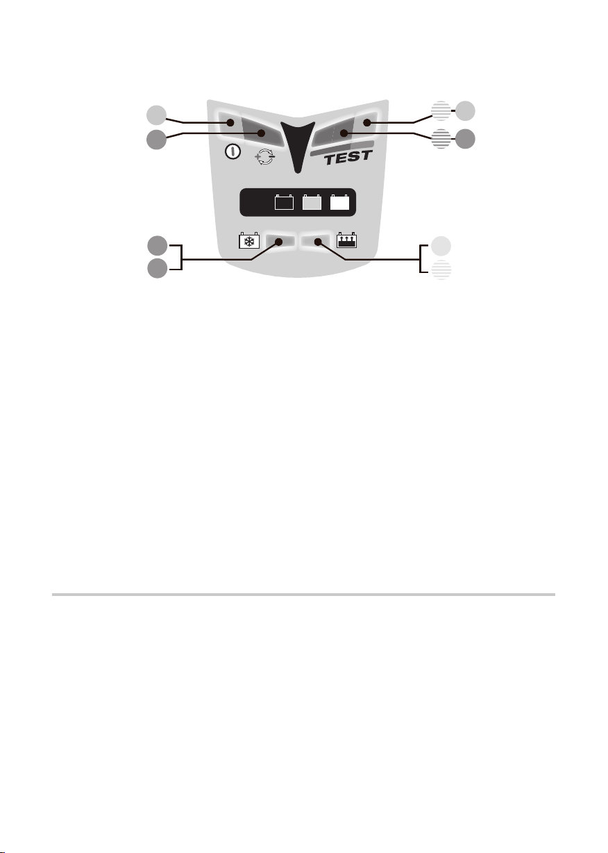
GUIDE RAPIDE – PANNEAU D’INFORMATION LED
12V
ALL
MF GEL
3.1
3.2
4.1
4.2
6 6
5 5
2
1
Tous les details sur LEDs ou programme dans le manuel – mêmes numéros
ENTRETIENTEST
ACTIVATION
DESULFATE
1. LED #1 - Marche. Cette LED confirme la présence d’alimentation AC vers le chargeur.
2. LED #2 polarités inverses – connexions erronées en sortie. Corriger pour activation.
3. Activation de circuit et récupération de batteries fortement déchargées
CHARGE
VERIF.
3.1 ACTIVATION - Si le V batterie est > 2V, la LED #3 s’allume brièvement pour confirmer l’activation.
Plupart des batteries : la LED #3 s’éteint de suite et la LED #4 s’allume.
3.2 RÉCUPÉRATION - pour batteries négligées ou « à plat ». La LED 3 reste allumée en fixe.
Si l’étape 3 n’a pas été fructueuse après 2h, l’étape 4 s’engage automatiquement.
4. Charge et vérification de charge
4.1 CHARGE : La LED #4 allumée en fixe indique l’étape de charge principale.
4.2 VÉRIFICATION : LA LED #4 clignote alors que le circuit vérifie le niveau de charge. Si la batterie requiert plus de
charge, le programme repasse en mode CHARGE. Plusieurs retours possibles. Les réversions font que la LED
#4 alterne de façon irrégulière entre un état fixe ou clignotant.
Si la LED# 4 a clignoté durant 30 minutes d’affilée (ou si les étapes 3 + 4 n’ont pas été achevées sous 48h),
l’étape 5 s’engage et un test de rétention de voltage commence.
5. 6. Tests de rétention et entretien de batterie – alternance toutes les 30 min.
5. Si batterie en bon état, la LED #5 clignote durant les 30 minutes de test. PAS DE COURANT DE CHARGE.
6. La LED # 6 (état fixe) peut remplacer la # 5 si le voltage de batterie chute durant le test.
Lisez les§ 6 dans le manuel si la LED 6 s’allume durant cette période.
Entretien - charge flottante sous voltage sûr pour prévenir toute décharge.
Durant les périodes d’entretien de 30 minutes, la LED #5 (ou #6) s’allume alors de façon fixe. La batterie prend le
courant nécessaire pour compenser les pertes et consommations.
Les périodes de test et d’entretien continuent d’alterner toutes les 1/2h jusqu’à déconnexion. Le résultat de test
est réactualisé à chaque fois.
GARANTIE LIMITÉE
TecMate North America, 22–1100 Invicta Drive, Oakville, Ontario, Canada L6H 2K9, consent la présente garantie
au premier client utilisateur de ce produit, sans possibilité de transfert. TecMate North America garantit ce chargeur
pendant deux ans à compter de la date d’achat au détail contre les défauts de composants ou d’assemblage. Le
cas échéant, le chargeur sera réparé ou remplacé à la discrétion du fabricant. L’acheteur doit expédier, à ses frais,
l’appareil ainsi qu’une preuve d’achat au fabricant ou à son représentant agréé. Cette garantie limitée devient nulle
si l’appareil est utilisé ou manipulé de façon inadéquate ou s’il a été réparé par toute personne physique ou morale
autre que le fabricant ou un représentant agréé. Le fabricant n’offre aucune autre garantie que la présente, et exclut
expressément toute garantie contre les dommages conséquentiels.
CECI EST LA SEULE GARANTIE EXPRESSÉMENT CONSENTIE PAR LE FABRICANT. CELUI-CI N’ASSUME ET N’AUTORISE
QUICONQUE A ASSUMER OU ETABLIR TOUTE AUTRE OBLIGATION LIÉE À CE PRODUIT, AUTRE QUE CETTE GARANTIE
LIMITÉE EXPRESSÉMENT CONSENTIE.
Page 7

7
CHARGEUR-DIAGNOSTIC AUTOMATIQUE POUR BATTERIES
PLOMB-ACIDE 12V.
Recommandé pour modèles 2-35 Ah. Incompatible avec piles non-rechargeables, NiCd, NiMH, Li-Ion.
Alimentation : 110-120V~ 0.075A. Sortie 0.6A 9W (maximum).
IMPORTANT : LIRE COMPLÈTEMENT CE MODE D’EMPLOI AVANT D’UTILISER L’APPAREIL.
AVERTISSEMENT DE SÉCURITÈ ET NOTES :
flammes à proximité. Débranchez la prise 110V-120V avant d’établir/supprimer une connexion à la batterie. L’acide
de batterie est hautement corrosif. Portez des vêtements protecteurs et évitez tout contact. Contact accidentel : lavez
avec de l’eau et du savon. Les bornes de la batterie ne doivent pas être lâches, sinon faites-les contrôler par un
professionnel. Si elles sont corrodées, utilisez une brosse en chiendent ; si elles sont sales ou graisseuses, utilisez un
chiffon et du détergent. N’utilisez le chargeur que si sa connectique est en parfait état. Si le câble d’alimentation est
endommagé, faites-le remplacer par le fabricant, son distributeur, ou autre atelier qualifié. Protégez votre chargeur
de l’humidité, acide, et vapeurs acides durant l’utilisation et l’entreposage. Tout dommage engendré par la corrosion,
l’oxydation ou un court-circuit interne ne sera pas couvert par la garantie. Eloignez la batterie du chargeur pendant la
charge pour éviter toute exposition à l’acide et à ses vapeurs. Si utilisé en position horizontale, placez le chargeur sur
une surface plane et dure, mais PAS sur une surface plastique, textile, ou en cuir. Vous pouvez également utiliser les 4
orifices situés aux extrémités du chargeur afin de le fixer sur toute surface verticale adéquate.
EXPOSITION À DES LIQUIDES : en utilisation horizontale (surface plane), ce chargeur est conçu pour résister à
l’exposition aux liquides qui tomberaient accidentellement sur le boîtier, ou à une pluie légère. Toutefois, ne jamais
laisser aucun liquide s’accumuler sous ou autour de la base. Une exposition prolongée à des liquides tombants ou à
la pluie est à déconseiller. Une durée de vie supérieure résultera d’une telle précaution. Une panne due à l’oxydation
résultant d’une pénétration de liquide dans les composants électroniques ne sera pas couverte par la garantie. Ne
jamais exposer aucun élément de connexion à la pluie ou à la neige.
CONNEXION À UNE BATTERIE : 2 sets de connexion interchangeables sont fournis. Un set avec pinces crocodiles
pour une charge hors-véhicule, l’autre avec œillets en métal pour une connexion à demeure sur les bornes de
la batterie et, à l’autre extrémité, un capuchon refermable en caoutchouc protégeant le connecteur bipolaire. Ce
deuxième set permet une connexion sûre et aisée pour un maintien de batterie alors que celle-ci est elle-même
connectée au véhicule. Le capuchon en caoutchouc doit être refermé lorsque le chargeur est déconnecté et/ou
avant d’utiliser le véhicule, de façon à protéger le connecteur bipolaire de la saleté et de l’humidité. Faites appel à
une assistance professionnelle pour la fixation des œillets métalliques aux bornes de la batterie. Eloignez autant que
possible le connecteur bipolaire de la batterie et assurez-vous qu’il ne puisse se prendre dans aucune pièce mobile
du véhicule ou être pincé ou endommagé par des parties tranchantes. Le fusible en ligne monté sur le set à oeillets
est là pour protéger la batterie dans de tels cas de court-circuit entre les conducteurs positif et négatif. Remplacez
toujours le fusible par un modèle identique, de 7.5A.
NOTES IMPORTANTES :
1. Lorsque vous chargez une batterie de voiture ou si vous utilisez le set à pinces, déconnectez et ôtez d’abord la
batterie du véhicule et placez-la dans un endroit bien ventilé.
2. Si la batterie est profondément déchargée (et éventuellement sulfatée), il est essentiel de la déconnecter du
véhicule avant d’y connecter le chargeur pour une tentative de récupération. Le mode spécial de récupération
ne peut s’initialiser s’il détecte que la batterie est toujours connectée à un faisceau électrique de véhicule,
celui-ci offrant une résistance électrique inférieure à celle de la batterie seule. Toutefois, si la batterie en état
de décharge profonde n’est pas démontée du véhicule lors de la tentative de récupération, ni la batterie ni
l’électronique embarquée du véhicule ne seront endommagées.
3. Si vous désirez toutefois connecter le chargeur à une batterie automobile en utilisant les pinces de charge
et sans déconnecter et démonter la batterie au préalable, connectez d’abord une pince à la borne non reliée
au châssis, puis l’autre pince au châssis, bien éloignée de la batterie et de l’alimentation en carburant. Ne
connecter au réseau qu’ensuite. Déconnectez toujours dans l’ordre inverse.
Batterie = présence de GAZ EXPLOSIFS – évitez étincelles et
Page 8

8
UTILISER L’OPTIMATE™3+
Les points ci-dessous sont numérotés de la même façon que le guide rapide ci-avant.
1. et 2. Connexions et Alimentation
Connectez le chargeur à la batterie : la pince ROUGE à la borne POSITIVE (POS, P, +), la pince NOIRE à la borne
NÉGATIVE (NEG, N,–). Vous êtes maintenant prêt à commencer :
1. Connectez le chargeur à une prise réseau CA fournissant de 110 à 120V. La LED d’alimentation (#1) doit
s’allumer. Sinon, contrôlez la prise réseau et la connexion.
2. Si la LED d’inversion de polarités s’allume, les connexions à la batterie sont erronées. Le chargeur est protégé
contre cette erreur, aucun dommage n’est à craindre – désactivation automatique. Déconnectez l’alimentation,
inversez les connexions à la batterie et reconnectez l’alimentation.
3.
Activation du circuit et récupération de batteries fortement déchargées / négligées
Pour des raisons de sécurité, pour initialiser son circuit de sortie, l’OptiMate™ doit être connecté au réseau 110-120V
AC et doit détecter qu’une batterie ayant au moins 2V est connectée. Si ces conditions ne sont pas remplies, seule la
LED d’alimentation (#1) s’allumera.
3.1 Dès l’activation du circuit de sortie, la LED orange #3 (DÉSULFATATION) s’allume brièvement et l’OptiMate
vérifie si la batterie peut être chargée de façon efficace par le programme à étapes multiples. Si c’est le cas,
la LED de CHARGE jaune (#4) remplacera la LED orange.
3.2 Si la batterie est « à plat » (fortement déchargée ou sulfatée), la LED DESULFATE peut rester allumée durant 2
heures max. et un voltage élevé sera appliqué pour forcer un petit courant dans la batterie afin de la récupérer.
Durant cette période, le voltage est limité à 20V. Le circuit évalue la probabilité de récupération de la batterie
sous cette tension. Si et dès que la batterie est à même d’accepter le petit courant, le voltage se réduira
automatiquement jusqu’à ce que la batterie puisse être à nouveau chargée par le programme normal.
A ce moment, et de toute façon après deux heures au plus, le mode de charge normal s’activera (§4).
NOTE : Une batterie fortement déchargée depuis longtemps peut avoir subi des dommages irréversibles dans une ou
plusieurs cellules. De telles batteries pourraient surchauffer durant la charge ; il faut stopper celle-ci immédiatement
si une batterie devenait exagérément chaude au toucher.
4. Charge et vérification de charge
4.1 Etape de CHARGE principale (LED 4 fixe) : un courant constant de 0.6A est délivré, provoquant une montée de
voltage graduelle dans la batterie. Lorsque celui-ci atteint 14.3V, l’OptiMate
VÉRIFICATION DE CHARGE.
4.2 VÉRIFICATION DE CHARGE (LED 4 clignotante) : le voltage de charge est maintenant limité à 13.6V durant 30
minutes alors que le niveau de charge est vérifié. Si la batterie nécessite davantage de charge, le programme
repassera en mode de CHARGE principal (§ 4.1) et la LED jaune #4 se rallumera en fixe. Dès que le voltage
aura à nouveau remonté, signalant l’approche de la pleine charge, le circuit repasse en VÉRIFICATION et la
LED #4 recommence à clignoter. Ces réversions auront lieu autant de fois que nécessaire afin de réduire la
demande de courant émanant de la batterie à moins de 200mA à 13,6V (valeurs typiques pour une batterie
qui a accepté autant de charge que son état initial le permettait). Dès que le circuit a constaté que la charge
est adéquate (la LED #4 ayant clignoté en continu durant 30 minutes pleines), le test de rétention de voltage
commence (§ 5).
NOTE Certaines batteries MF-AGM qui auraient été négligées pourraient entraîner l’avancement du programme à
l’étape de VÉRIFICATION (4.2) sans passer par la charge principale (§ 4.1). Le système de diagnostic détectera et
corrigera cette anomalie. Le circuit oscillera entre les modes de charge et de vérification, comme décrit dans le § 4.2.
™
active l’étape d’absorption et de
5. et 6.
Alternance entre tests de rétention de voltage et maintien chaque demi heure
La première période de TEST de RÉTENTION DE VOLTAGE de 30 minutes suit le § 4.2 ; s’ensuit une période de
MAINTIEN. Ces périodes de TEST et MAINTIEN alternent ensuite aussi longtemps que la batterie reste connectée. La
délivrance de courant à la batterie est interrompue durant 30 minutes pour l’étape de test, ce qui permet à la batterie
de se reposer (minimisant ainsi les pertes d’eau de l’électrolyte). Le circuit surveille le déclin de voltage de la batterie
afin de déterminer son aptitude à retenir une charge et à délivrer de la puissance.
5. Batteries en bon état : la LED verte (#5) clignotera durant toute la période de test, et passera en fixe lorsque
le mode de maintien s’activera. Si la batterie reste connectée au véhicule et qu’elle est soumise à une
™
Page 9

9
consommation (lampes, accessoires etc), la LED verte (clignotante) pourrait être remplacée par la LED rouge
(fixe) durant la période de test.
6. Normalement, la LED rouge signale une batterie défectueuse. Mais il peut se produire qu’une batterie en bon
état et qui est restée connectée au véhicule subisse un résultat de test mauvais, à cause d’une consommation
de courant excessive par des accessoires ou d’une perte de courant dans le faisceau électrique du véhicule.
Ôtez la batterie du véhicule et reconnectez l’OptiMate. Si un meilleur résultat (LED verte) est alors atteint,
le problème provient sans doute du faiseau électrique du véhicule. Par contre si la LED rouge s’allume de
nouveau pendant le test, la batterie est probablement défectueuse. Lisez le NOTE supplémentaire.
NOTE SUPPLÉMENTAIRE SUR LA LED ROUGE #6 : Si le test sur batterie hors-véhicule donne encore un résultat
de LED rouge, nous vous conseillons de faire vérifier la batterie chez un professionnel équipé d’un chargeurtesteur BatteryMate
™
( www.batterymate.com ) ou d’un testeur digital TestMate™ (www.testmate.com) pour un
test approfondi. La LED rouge signifie qu’après avoir été chargée, le voltage de la batterie n’a pu rester à un niveau
acceptable, ou qu’elle s’est révélée irrécupérable malgré l’étape de désulfatation. Ceci est peut-être dû à un défaut
de la batterie elle-même, comme un court-circuit interne ou une sulfatation totale ou, dans le cas d’une batterie
restée connectée à un véhicule, la LED rouge (6) pourrait signaler une perte de courant sur un faisceau défaillant, un
interrupteur ou contact dégradé, ou encore la présence d’accessoires consommant du courant. Une consommation
soudaine comme l’allumage des phares alors que le chargeur est connecté peut aussi entraîner une chute de voltage
significative. Ôtez la batterie dans tous les cas, reconnectez l’OptiMate
™
et recommencez le programme.
NOTE FINALE SUR LE TEST DE RÉTENTION DE VOLTAGE : Ce test a un caractère fortement indicatif mais pas
nécessairement conclusif quant à l’état d’une batterie donnée, celui-ci pouvant être établi avec plus de précision à
l’aide du TestMate
charge interne. L’on peut également contacter un professionnel équipé d’un BatteryMate
™
mini, qui peut tester une batterie 12V sur véhicule durant le démarrage ainsi que le système de
™
150-9 ou d’un TestMate™
digital.
Maintenance de batterie automatique
Les périodes de maintenance de 30 minutes suivent et alternent avec les périodes de test de même durée, au cours
desquelles aucun courant n’est délivré. Ce cycle « à 50% » permet aux batteries de se « reposer » chaque demi heure
et de minimiser les pertes d’eau par évaporation, dans le cas de batteries à bouchons. Il en résulte une optimisation
significative de la durée de vie de batteries à usage irrégulier ou saisonnier. Le circuit offre du courant à la batterie
sous une limite sûre de 13.6V (charge « flottante »), permettant à la batterie de « tirer » tout petit courant nécessaire
à son maintien en état de pleine charge (ou proche) et de compenser les consommations dues à des accessoires
comme système anti-vol, ordinateur de bord etc, ou à l’auto-décharge graduelle de la batterie elle-même.
NOTE : Maintenances prolongées : Après l’activation du chargeur, il est conseillé d’observer les indications LED de
temps à autre jusqu’à affichage du résultat. Si la batterie devient chaude au toucher à quelque moment que ce soit,
déconnectez-la du chargeur et faites-la tester par un professionnel équipé d’un BatteryMate
™
TestMate
II, spécifiquement développé pour les batteries de motos. Au moins une fois toutes les deux semaines,
™
ou d’un testeur digital
vérifiez que les connexions entre le chargeur et la batterie soient franches et, s’il s’agit d’un modèle à bouchons,
déconnectez du chargeur, contrôlez les niveaux d’électrolyte et faites l’appoint si nécessaire (avec de l’eau distillée,
PAS avec de l’acide). Ensuite, reconnectez. Lorsque vous manipulez des batteries ou êtes à proximité, veillez à
observer les AVERTISSEMENTS DE SÉCURITÉ ci-dessus.
Temps de charge
Le temps requis par l’OptiMate™3+ si la batterie est complètement déchargée mais toutefois en bon état, est environ
égal à la capacité de la batterie en Ah. Il faudra donc à peu près 12 heures pour qu’une batterie de 12Ah soit amenée
au stade de contrôle de charge final (§ 5). Les batteries en état de décharge profonde peuvent prendre beaucoup plus
de temps.
NOTE : Le temps de charge total des étapes 4.1 et 4.2 n’est pas limité. Si vous rechargez une batterie auto
sévèrement déchargée à l’aide de l’OptiMate
™
3+, il est probable qu’une pleine charge ne puisse être atteinte même
après quelques jours. Il se peut que durant ces journées de travail à pleine charge, le chargeur soit devenu fort
chaud. Mieux vaut alors le laisser au repos jusqu’à ce qu’il soit revenu à la température ambiante avant de relancer la
charge.
Déconnexion
Déconnectez d’abord l’OptiMate™ du réseau AC puis de la batterie. Il faut toujours agir dans cet ordre avant de le
reconnecter à une batterie – la même ou une autre. Refermez le capuchon en caoutchouc sur l’embout du connecteur
à demeure (SAE-71) qui pourrait être connecté à la batterie, afin de le protéger de l’humidité et des impuretés.
Page 10

10
GUÍA RÁPIDO – PANEL DE INFORMACIÓN LED
12V
ALL
MF GEL
3.1
3.2
4.1
4.2
6 6
5 5
2
1
Todos detalles sobre los LEDs y el programa en el manual – mismos números #
MANTIENEPRUEBA
ACTIVA
DESULFATA
1. LED #1 - marcha. Este LED confirma la alimentación AC hacia el cargador.
2. LED #2 - polaridades invertidas – conexiones erróneas en salida. Corregir para activación.
3. Activación del circuito y recuperación de baterías muy descargadas
CARGA
VERIFICA
3.1 ACTIVACIÓN - si el V de batería > 2v el LED #3 se enciende brevemente para indicar la activación.
Para la mayoría de las baterías: el LED #3 se apaga pronto y el LED #4 se enciende.
3.2. RECUPERACIÓN – para baterías descuidadas. El LED #3 quedase encendido en fijo.
Si la etapa 3 no era conclusiva después de 2h, la 4 se inicia automáticamemente.
4. Carga y verificación de carga
4.1. Carga: el LED 4 fijo indica la etapa de carga principal.
4.2. Verificación: el LED #4 parpadea mientras que el circuito verifique el nivel de carga. Si la batería necesita más
carga, el programa vuelve en modo de carga. Posibilidad de reversiones múltiples.
Las reversiones hacen que el LED #4 alterne irregularmente entre un estado fijo o parpadeante.
Si el LED #4 parpadeó continuamente durante 30’ (o si las etapas 3 y 4 no se terminarón dentro de 48h), la etapa
5 se inicia y un test de rétención de voltaje comienza.
5. 6. Tests de retención y mantenimiento de batería – alternación cada 30 min.
5. Batería en buen estado: el LED #5 parpadea durante los 30’ de test. Ninguna carga.
6. El LED #6 puede sustituirse al #5 si el voltaje de batería se cae durante el test.
Lee el § 6 en el manual si il LED #6 se enciende durante este período.
Mantenimiento - carga flotante con un voltaje seguro para evitar toda descarga.
Durante los períodos de mantenimiento de 30’, el LED #5 (o #6) es ahora fijo. La batería “tira” la corriente que
necesita para compensar las pérdidas y los consumos.
Los períodos de test y de mantenimiento siguen alternándose toda 1/2h hasta la desconexión. El resultado de
test se reactualiza al final de cada ciclo.
GARANTÍA LIMITADA
TecMate North America, 22–1100 Invicta Drive, Oakville, Ontario, Canada L6H 2K9, establece esta garantía limitada
en favor del primer propietario que utilice este aparato. Esta garantía limitada no es transferible.
TecMate North America garantiza este aparato durante los dos años siguientes a la fecha de compra por su primer
usuario contra las fallos de materiales y de montaje. En este caso y a discreción del fabricante el aparato podrá ser
reparado ó reemplazado. La gestión y los costes relativos al transporte del aparato acompañado por una prueba de
compra al fabricante ó a uno de sus representantes autorizados serán por cuenta del cliente. Esta garantía limitada se
anula en caso de uso ó tratamiento inadecuado, ó de reparación hecha por toda persona o organización otra diferente
al fabricante ó uno de sus representantes autorizados. El fabricante no cumple con otra garantía que esta garantía
limitada y expresamente excluye toda forma de garantía contra otros daños que los que sufra el aparato por sí mismo.
ESTO CONSTITUYE LA UNICA GARANTÍA LIMITADA VALIDA. El FABRICANTE NO RECONOCE A QUIENQUIERA EL
DERECHO DE EJERCER Ó DE TRANSMITIR NINGUN DERECHO RELATIVO AL PRODUCTO VENDIDO QUE SEA OTRO QUE
EL QUE SE DERIVA DE ESTA GARANTÍA LIMITADA EXPRESA
Page 11

11
CARGADOR AUTOMÁTICO Y DIAGNÓSTICO PARA BATERÍAS
PLOMO-ÁCIDO 12V
Recomendado para baterías 2-35 Ah. Incompatible con pilas non-recargables NiCd, NiMH, Li-Ion. Alim.
110-120V~ 0.075A. Salida: 0.6A 9W (máximo).
IMPORTANTE: LEE COMPLETAMENTE ESTE MANUAL ANTES DE UTILIZAR EL OPTIMATE.
ADVERTAMIENTOS DE SEGURIDAD Y NOTAS:
chispas ni de fuego. Desconecta de la red 110V-120V antes de establecer/suprimir una conexión a la batería. El ácido
de la batería es altamente corrosivo. Lleva ropa protectora y evite todo contacto. Contacto accidental: lava con agua y
jabón. Los bornes de la batería no deben estar flojos; en caso contrario haz que sean revisados por un profesional. Si
están corroídos límpialos con un cepillo de raíces (grama). Si tienen grasa/suciedad límpialos con un trapo mojado en
detergente. No utiliza el OptiMate
dañado tiene que ser reemplazado por el fabricante, su distribuidor, ó otro taller cualificado. Protege tu cargador de
la humedad, del ácido y vapor de ácido durante el uso y el almacenaje. En caso de no respetar estas advertencias la
garantía quedará invalidada. Aleja lo más posible el cargador de la batería durante la carga y, si no lo fijas en la pared
ponlo sobre una superficie firme y plana que no sea textil, plástico, ó cuero. También se puede utilizar los 4 orificios a
las extremidades del OptiMate
™
si todos los cables no están en perfecto estado. Si el cable de alimentación está
™
para fijarlo en toda superficie vertical adecuada.
EXPOSICIÓN A LÍQUIDOS: Si esta colocado por una superficie horizontal y plana, este cargador fue desarrollado
para resistir a líquidos que hubieran sido derramados de forma accidental o a intemperies ligeras. No obstante, no
se recomiendan las exposiciones prolongadas que podrían menguar la duración de vida del cargador. Los desgastes
resultando de la oxidación debida al ataque eventual de líquidos en los componentes electrónicos no se cubren por la
garantía. Nunca exponer los elementos de conexión a la lluvia o la nieve.
CONEXIÓN A UNE BATERÍA: Se entregan 2 conectores, uno con pinzas para conexiones fuera del vehículo, y otro
con ojales para una fijación permanente, facilitando las conexiones/desconexiones frecuentes al vehículo. Utilización
de las pinzas: quita la batería del vehículo y ponla en un lugar bien ventilado. Para el montaje del set con ojales:
recomendamos que sea realizado por un profesional. Aleja el juego de conexión lo más posible de la batería y haz que
no pueda rozarse con elementos móviles o ser dañado por partes cortantes. Cierra el capuchón estanco tan pronto
como se termine la carga para evitar todo ingreso de suciedad y de humedad. Fusible defectuoso en el conector:
Reemplázalo por un fusible de mismo tipo y amperaje – 7.5A.
NOTAS IMPORTANTES:
1. Cuando cargas una batería de coche o si utilizas el juego con pinzas, desconecta y quita primero la batería del
vehículo y ponla en un lugar bien aireado.
2. Si la batería es sumamente descargada (y posiblemente sulfatada) es esencial desconectarla del vehículo
antes de conectar el cargador para hacer una tentativa de recuperación. El modo de recuperación no puede
inicializarse si el circuito detecta que una batería todavía es conectada por la red eléctrica del vehículo,
porque la misma esta opondrá una resistencia eléctrica inferior a lo que habría prevalido para la batería sola.
No obstante, si la batería no se quita del vehículo para efectuar la tentativa de recuperación, la batería y los
sistemas electrónicos no se dañarán.
3. Si todavía deseas conectar el cargador a una batería de coche utilizando las pinzas de carga y sin desconectar
quitar la batería, conecta primero una pinza al borne que no esta conectado al chasis, y después la otra, lo
más alejada posible de la batería y de la alimentación de gasolina. Sólo conectar a la red después. Siempre
desconectar en orden inverso.
batería = presencia de gases explosivos– no manipular cerca de
Page 12

12
UTILIZAR EL OPTIMATE™3+
LOS PUNTOS A CONTINUACIÓN TIENEN EL MISMO NÚMERO QUE EL GUÍA RÁPIDO.
1. y 2. Conexiones y alimentación
Conecta el cargador a la batería: la pinza ROJA al borne POSITIVO (POS, P, +), la pinza NEGRA al borne NEGATIVO
(NEG, N,–). Ahora estas listo(a) para empezar:
1. Conecta el cargador a una toma CA 110-120V. El LED de alimentación (#1) debe encenderse. Si no, controla el
enchufe y la conexión.
2. Si el LED de inversión de polaridades se enciende, las conexiones a la batería son erróneas. El cargador esta
protegido contra este error, ningún daño posible – desactivación automática. Desconecta la alimentación,
inverte las conexiones a la batería y reconecta la alimentación.
3. Activación del circuito y recuperación de baterías sumamente descargadas/
descuidadas
Por razones de seguridad, el OptiMate™ debe ser conectado a la red 110-120V y detectar una batería con una tensión
mínima de 2V para que su circuito de salida pueda inicializarse. Si no se cumple con estas condiciones, sólo el LED
de alimentación (#1) se encenderá.
3.1 Desde la activación del circuito de salida, el LED naranjo #3 (DESULFATACIÓN) se enciende brevemente y el
3.2 Si la batería es sumamente descargada incluso sulfatada, el LED DESULFATA se quedará encendido durante
NOTA: Una batería sumamente descargada desde mucho tiempo podría haber sufrido daños irreversibles en una o
más células. Tales baterías podrían sobrecaldarse durante la carga; se debería parar inmediatamente la misma si una
batería volviese demasiado calda al tocar.
4. Carga y verificación de carga
4.1 Etapa de CARGA principal (LED #4 fijo): una corriente constante de 0.6A se suministra, lo que resulta en una
4.2
NOTA Ciertas baterías MF-AGM que hubieran sido descuidadas podrían llegar a una avanza del programa hacia la
etapa de VERIFICACIÓN (4.2), sobrepasando la etapa de carga principal (§ 4.1). El sistema de diagnóstico detectará y
corregirá esta anomalía. El circuito oscilará entre los modos de carga y de verificación, como se describe en el § 4.2.
5. y 6.
Alternanción cada ½ hora: tests de retención de voltaje y mantenimiento
El primero período de TEST de RETENCIÓN DE VOLTAJE de 30 minutos sigue el § 4.2; un período de MANTENIMIENTO
sigue después. Estos períodos de TEST y MANTENIMIENTO se alternan entonces por tanto tiempo que la batería se
quede conectada. La suministra de corriente a la batería se interrumpe durante 30 minutos para la etapa de test,
lo que permite a la batería de reposar (así minimizando las pérdidas de agua en el electrólito). El circuito vigila toda
caída de voltaje de la batería a fin de determinar su aptitud para retener una carga y entregar una potencia.
5. Baterías en buen estado: el LED verde (#5) parpadeará durante toda el período de test y se volverá fijo tan
™
OptiMate
el caso, el LED de CARGA amarillo (#4) se sustituirá pronto al LED naranjo.
2 horas máx. y un alto voltaje se aplicará para forzar una baja corriente en la batería para tratar de
recuperarla. El límite de voltaje de carga es fijado a 20V, pero con una corriente muy baja y segura. Si y tan
pronto que la batería sea capaz de aceptar esta baja corriente, el voltaje se reducirá automáticamente hasta
que la batería de nuevo pueda ser cargada normalmente. A este momento, y de toda forma después dos horas
máximo, el modo de carga normal se activará (§4).
subida de voltaje gradual en la batería. Cuando la tensión alcanza los 14.3V, el OptiMate
absorción y de VERIFICACIÓN DE CARGA.
VERIFICACIÓN DE CARGA (LED #4 parpadeante): el voltaje de carga ahora es limitado a 13.6V durante 30 minutos
mientras que el nivel de carga esté verificado. Si la batería necesita más carga, el programa volverá de nuevo en
modo de CARGA principal (§ 4.1) y el LED amarillo #4 se encenderá de nuevo en fijo. Tan pronto que el voltaje
hubiese subido de nuevo, indicando que acerca la plena carga, el circuito pasa en VERIFICACIÓN y el LED #4
vuelve parpadeando. a fin de reducir la “petición” de corriente emanando de la batería, hacia un nivel inferior a
200mA a 13,6V (valores típicos para una batería que aceptó una carga tal que su condición de base lo permitió).
Tan pronto que el circuito constata una carga adecuada (el LED #4 habiendo parpadeado en continuo durante 30’),
el test de retención de voltaje comienza (§ 5).
pronto que se activará el modo de mantenimiento.
verifica si la batería puede ser cargada de forma eficaz por el programa a etapas múltiples. Si llega
™
activa la etapa de
Page 13

13
6. Si la batería quedase conectada al vehículo y que sufre un consumo (faros, accesorios etc), el LED verde
podría sustituirse por una indicación “LED rojo fijo” durante este período de test, quita la batería del vehículo
y reconecta el OptiMate
red eléctrica del vehículo. Te aconsejamos leer la nota siguiente y consultar con un especialista en electricidad
auto-moto.
NOTA ADICIONAL SOBRE EL LED rojo #6: Si el test con la batería fuera del vehículo llega a un resultado “LED rojo”,
te aconsejamos tener la batería verificada por un profesional que utiliza un cargador-tester BatteryMate
batterymate.com ) o un tester digital TestMate
rojo significa que después de haber sido cargada, el voltaje de la batería no pudo quedarse a un nivel aceptable o que
se reveló como irrecuperable, a pesar de la etapa de desulfatación. Eso puede ser debido a un defecto de la batería
misma, como un cortocircuito interno o una sulfatación total ó, si la batería se quedó conectada a un vehículo, el LED
rojo (#6) podría indicar una pérdida de corriente por un circuito defectuoso, un interruptor o contacto dañado, o la
presencia de accesorios que consumen una corriente. Un consumo súbito como el encendido de los faros mientras
que el cargador sea conectado también podría llegar a una caída de voltaje significativa. En todos casos quita la
batería, reconecta el OptiMate
NOTA FINAL SOBRE EL TEST DE RETENCIÓN DE VOLTAJE: Este test debe considerarse como fuertemente indicativo
y no conclusivo en cuanto al estado de una batería. Un diagnóstico más preciso puede ser establecido al medio de
un TestMate
de carga interno. También se puede contactar con un profesional que disponga de un BatteryMate
TestMate
™
mini, que puede comprobar una batería 12V por el vehículo durante el arranque, así como el sistema
™
digital.
™
. Si ahora se indica un mejor resultado, el problema proviene probablemente de la
™
™
(www.testmate.com) para una comprobación más completa. El LED
™
y recomienza el programa.
( www.
™
150-9 o de un
Mantenimiento de batería automático
Los períodos de mantenimiento de 30 minutos siguen y alternan se con los períodos de test de misma duración – no
se suministra ninguna corriente durante los últimos. Este ciclo “a 50%” permite que las baterías puedan “reposar”
cada ½ hora, así minimizando las pérdidas de agua por evaporación en el caso de baterías con tapones. El resultado
es una optimización significativa de la longevidad de las baterías que se utilizan irregularmente o de temporada.
El circuito ofrece una corriente a la batería con una límite segura de 13,6V (carga fluctuante), lo que permite a la
batería de “tirar” toda pequeña corriente que sea necesaria para que pueda quedarse en (o cerca de) un estado de
plena carga y para compensar los consumos debidos a accesorios como sistemas antirrobos, ordenador de bordo etc,
o para evitar toda auto-descarga gradual de la batería misma.
NOTA: Mantenimientos prolongados: Después de la activación del cargador, se aconseja observar las indicaciones
LED a tiempos, hasta que el resultado se indique. Si la batería vuelve calda al tocar en cualquier momento que sea,
desconéctala del cargador y téngala comprobada por un profesional que disponga de un BatteryMate
digital TestMate
™
II, que fueron específicamente diseñado para baterías de motos. Al menos cada dos semanas
™
o de un tester
verifica que las conexiones entre el cargador y la batería sean firmas y, si se trata de un modelo con tapones,
desconéctala del cargador, controla los niveles de electrólito y llena a nivel cuando necesario (con agua destilada pero
NO con ácido) y reconecta. Cuando manipulas (o estas cerca de) baterías, por favor aplica los ADVERTAMIENTOS DE
SEGURIDAD más arriba.
Tiempo de carga
El tiempo necesario para recargar una batería totalmente descargada pero en buen estado al medio del OptiMate™3+
es más o menos igual a la capacidad de la batería en Ah. Entonces se necesita cerca de 12 horas para que una
batería de 12Ah alcance la etapa de control de carga final (§ 5). Las baterías en estado de descarga profunda pueden
necesitar mucho más tiempo.
NOTA: El tiempo de carga total en 4.1 y 4.2 no esta limitado. Si estas recargando una batería de coche muy
descargada al medio del OptiMate
™
3+, se puede que la plena carga no se pueda alcanzar dentro de 3-4 dias. En
tal caso desconecta la alimentación en fin de ciclo, espera un momento reconecta a la red AC para reinicializar el
programa. Se puede que durante estas dos jornadas de trabajo a plena carga, el cargador volviese muy caldo. En tal
caso se recomienda dejarlo reposar hasta que vuelváse la temperatura ambiente antes de recomenzar la carga.
Desconexión
Desconecta primero el OptiMate™ de la red AC y después de la batería. Siempre se debe actuar en este orden priorero
a establecer una nueva conexión – a la misma batería o a otra. Cierra el capuchón de goma del conector permanente
(SAE-71), a fin de le proteger el mismo contra la humedad y suciedad.
Page 14

14
GUIA RÁPIDO – PAINEL INFORMATIVO LED
12V
ALL
MF GEL
3.1
3.2
4.1
4.2
6 6
5 5
2
1
Todos os detalhes sobre LEDs ou programa no manual - mesmos números #
MANUTENÇÃOTESTE
ACTIVAÇÃO
DESULFATE
1. LED #1 - Activado. Este LED confirma a presença de alimentação AC para o carregador.
2. LED #2 Polaridades invertidas – conexões erradas na saída. Corrigir para activação.
3. Activação do circuito e recuperação de baterias fortemente descarregadas
CARGA
VERIF.
3.1 ACTIVAÇÃO - Se a V bateria é > 2V, O LED #3 acende-se brevemente para confirmar a activação.
Maioria das baterias: o LED #3 apaga-se logo e o LED #4 acende-se.
3.2 RECUPERAÇÃO - para baterias desprezadas ou « vazias ». O LED #3 fica aceso em fixo..
Se a etapa 3 nâo foi frutuosa após 2h, a etapa 4 inicia-se automáticamente.
4. Carga e verificação de carga
4.1 CARGA: O LED #4 aceso em fixo indica a etapa de carga principal.
4.2 CARGA: O LED #4 aceso em fixo indica a etapa de carga principal.
4.2. VERIFICAÇÃO: O LED #4 pisca enquanto o circuito verifica o nível de carga. Se a bateria necessita mais carga,
o programa volta ao modo CARGA. Várias reversões possíveis. As reversões fazem que o LED #4 alterne de
maneira irregular entre um estado fixo ou intermitente.
Se o LED #4 piscou durante 30 minutos de seguida (ou se as etapas 3 + 4 nâo foram terminadas nas 48h), a
etapa 5 inicia-se e um teste de retenção da voltagem começa.
5. 6. Testes de retenção e manutenção de bateria – alternância todos os 30 min.
5 Se bateria em bom estado, o LED #5 pisca durante os 30’ de teste. SEM CORRENTE DE CARGA.
6 O LED #6 pode substituir o #5 se a voltagem da bateria quebra durante o teste.
Ler o § 6 no manual se o LED #6 se acende durante este periodo.
Manutenção – carga flutuante sub voltagem segura para prever qualquer descarga.
Durante os períodos de manutenção de 30’, o LED #5 (ou #6) aceso em posição fixa. A bateria tira a corrente
necessária para compensar as perdas e consumos.
Os periodos de teste e de manutenção continuam alternativamente todas as 1/2h até desligar. O resultado do
teste é réactualizado todas as vezes.
GARANTIA LIMITADA
TecMate North America, 22–1100 Invicta Drive, Oakville, Ontario, Canada L6H 2K9, consente a presente garantia
ao primeiro utilizador deste produto, sem possibilidade de transferibilidade. TecMate North America garante este
carregador durante dois anos a partir da data de compra ao retalhista, contra os defeitos dos componentes ou de
montagem. Se for o caso, o carregador será reparado ou substituído à discrição do fabricante. O comprador deve
enviar por sua própria conta, o aparelho assim como uma prova de compra, ao fabricante ou ao seu representante.
Esta garantia limitada, torna-se nula se o aparelho for utilizado ou manipulado de forma inadequada ou se tiver sido
reparado por toda outra pessoa física ou moral que o fabricante ou o seu representante. O fabricante não oferece
nenhuma outra garantia que a presente, e excluí expressamente toda garantia conta danos consequenciais.
ESTA É A ÚNICA GARANTIA EXPRESSAMENTE CONSENTIDA PELO FABRICANTE. ESTE NÃO ASSUME E NÃO AUTORIZA
QUEM QUER QUE SEJA A ASSUMIR OU ESTABELECER TODA OUTRA OBRIGAÇÃO LIGADA A ESTE PRODUTO, OUTRA
QUE ESTA GARANTIA LIMITADA EXPRESSAMENTE CONSENTIDA.
Page 15

15
CARREGADOR-DIAGNOSTICO AUTOMÁTICO PARA BATERIAS
CHUMBO-ÁCIDO.
Recomendado para modelos 12V. Incompatível com pilhas não recarregáveis, NiCd, NiMH, Li-Ion. Alim.
110-120V~ 0.075A. Saída 0.6A 9W (máximo).
IMPORTANTE: LER COMPLÈTEMENTE ESTAS INSTRUÇÕES ANTES DE UTIZAR O APARELHO.
ADVERTÊNCIA DE SEGURANÇA E NOTA:
nas proximidades. Desligar a tomada 110V-120V antes de estabelecer ou suprimir uma ligação à bateria. O ácido da
bateria é altamente corrosivo. Usar vestuário adequado e evitar qualquer contacto. Em caso de contacto acidental:
lavar com água e sabão. Os terminais da bateria não devem estar frouxos, caso contrário, devem ser controlados
por um profissional. Se estiverem corroídos, utilizar uma escova de aço ; se estiverem sujos ou engordurados, limpar
com um pano e detergente. Não utilizar se carregador, todas as conexões não estiverem em perfeito estado. Se o
cabo de alimentação estiver estragado, faça-o substituir pelo fabricante, distribuidor ou oficina qualificada. Proteger o
carregador da humidade, ácido, e vapores ácidos durante a utilização e o armazenamento. Qualquer prejuízo gerado
pela corrosão, pele oxidação ou curto-circuito interno não está coberto pela garantia. Afastar a bateria do carregador
durante a carga, para evitar qualquer exposição ao ácido e aos seus vapores. Se utilizado em posição horizontal,
colocar o carregador sobre uma superfície plana e dura, mas NÃO sobre uma superfície plástica, têxtil ou de cabedal.
Pode igualmente utilizar os 4 orifícios situados nas extremidades do carregador de modo a fixá-lo sobre qualquer
superfície vertical adequada.
EXPOSIÇÃOAOS LIQUIDOS: em posição horizontal (superfície plana), este carregador foi concebido para resistir à
exposição a líquidos que possam cair acidentalmente sobre a caixa, ou aos chuviscos. No entanto, não deixar nenhum
liquido acumular-se sob ou em redor da base. Uma exposição prolongada aos líquidos ou à chuva é desaconselhada.
Uma duração de vida superior resultará de tal precaução. Uma avaria ocasionada pela oxidação resultante da
penetração de líquidos nos componentes electrónicos não será coberta pela garantia. Nunca expor nenhum elemento
da conexão à chuva ou à neve.
CONEXÃO A UMA BATERIA: 2 CONJUNTOS DE CONEXÃO PERMUTÁVEIS SÃO FORNECIDOS. Um conjunto de pinças
crocodilo para uma carga fora do veículo, o outro com olhais metálicos para uma conexão directa e permanente aos
terminais da bateria do veículo, e na outra extremidade, um capuz de borracha que protege o conector bipolar. Este
segundo conjunto permite uma conexão segura e fácil para a manutenção da bateria enquanto está conectada ao
veículo. O capuz de borracha deve ser fechado ao desligar do carregador e /ou antes de utilizar o veículo, de forma a
proteger o conector bipolar da sujidade e humidade. Consulte um profissional para a fixação dos olhais aos terminais
da bateria. Afastar tanto quanto possível o conector bipolar da bateria e assegurar-se que não possa prender-se em
elementos móveis do veículo ou que seja danificado por elementos cortantes. O fusível em linha, instalado no cabo
de ligação com olhais, serve para proteger a bateria no caso de curto-circuito entre o positivo e o negativo. Substituir
sempre o fusível por um modelo idêntico, de 7.5A.
NOTAS IMPORTANTES:
1. No caso de meter em carga uma bateria de automóvel ou utilizar o conjunto de pinças, primeiro desligar e tirar
a bateria do veículo e colocá-la num local bem ventilado.
2. Se a bateria estiver profundamente descarregada (e eventualmente sulfatada), é indispensável desligá-la
e retirá-la de veículo antes de lhe o carregador para uma tentativa de recuperação. O modo especial de
recuperação não pode iniciar se detectar que a bateria se encontra ligada ao feixe eléctrico do veículo, pois
este oferece uma resistência inferior à da bateria. No entanto, se uma bateria em estado de descarga profunda
não for desmontada do veículo na tentativa de recuperação, nem a bateria, nem a electrónica do veículo serão
danificadas.
3. Se desejar contudo ligar o carregador a uma bateria automóvel utilizando as pinças de carga e sem desligar e
desmontar a bateria previamente, primeiro conectar uma pinça ao borne não ligado ao chassis, depois a outra
ao chassis, afastada o mais possível da bateria e da alimentação de combustível. Só depois, ligar à corrente.
Para desligar, respeitar a ordem inversa.
Bateria = presença de GASES EXPLOSIVOS – evitar faíscas e chamas
Page 16

16
UTILIZAÇÃO DO OPTIMATE™3+
OS PONTOS QUE SE SEGUEM SÃO ENUMERADOS DAMESMA FORMA QUE NO GUIA RÁPIDO.
1. and 2. Conexões e alimentação
Ligar o carregador à bateria: a pinça VERMELHA ao borne POSITIVO (POS, P, +), a pinça PRETA ao borne NEGATIVO
(NEG, N, –). Está agora pronto para iniciar:
1. Ligue o carregador à corrente 110 a 120V. O LED de alimentação (#1) deve acender-se. Caso contrário,
controlar a ficha e a tomada.
2. Se o LED de inversão de polaridade se acender é porque as ligações estão erradas. O carregador está
protegido para este tipo de erro, nenhum dano é possível – desactivação automática. Desligar da corrente,
inverter as conexões à bateria e ligar novamente à corrente.
3. Activação do circuito e recuperação de baterias fortemente descarregadas/
esquecidas
Por motivos de segurança, para inicializar o seu circuito de saída, o OptiMate™ deve estar ligado à corrente de
110-120V e deve detectar que uma bateria tendo pelo menos 2V está conectada. Se estas condições não estiverem
reunidas, só se acende o LED de alimentação (#1).
3.1 Logo depois da activação do circuito de saída, o LED laranja (#3) (DESSULFATAÇÃO) acende-se brevemente e
o OptiMate
múltiplas. Se for o caso, o LED de CARDA amarelo (#4) substitui o LED laranja quase imediatamente.
3.2 Se a bateria está completamente vazia (fortemente descarregada ou sulfatada). O LED “DESULFATE” ficará
aceso durante 2 horas no máximo e uma voltagem elevada (limitada a 20V) será aplicada de forma a forçar
uma pequena corrente na bateria afim de a recuperar.
NOTA: Uma bateria profundamente descarregada há muito tempo, pode ter sofrido danos irreversíveis numa ou várias
células. Tais baterias podem sobreaquecer durante a carga; deve-se então parar a mesma imediatamente se a bateria
se tornar quente ao tocar.
4. Carga e verificação de carga
4.1 Etapa de CARGA principal (LED #4 fixa): uma corrente constante de 0.6A é aplicada, provocando uma subida
gradual da voltagem na bateria. Quando atingir os 14.3V, o OptiMate
VERIFICAÇÃO DE CARGA.
4.2 VERIFICAÇÃO DE CARGA (LED #4 a piscar): a voltagem de carga é agora limitada a 13.6V durante 30 minutos
enquanto que o nível de carga está a ser verificado. Se a bateria necessitar de mais carga, o programa volta
a passar em modo de CARGA principal (§ 4.1) e o LED amarelo (#4) acende-se em fixo. Logo que a voltagem
tenha subido de novo, avisando a aproximação da plena carga, o circuito passará de novo em VERIFICAÇÃO e
o LED #4 irá de novo piscar. Estas reversões irão reproduzir-se tantas vezes quanto necessário, afim de reduzir
o pedido de corrente proveniente da bateria a menos de 200mA a 13.6V (valores típicos para uma bateria que
tanta carga que o seu estado inicial permitia). Assim que o circuito que a carga é a adequada (o LED #4 tendo
piscado constantemente durante 30 minutos), o teste de retenção de voltagem começa (§ 5).
NOTA Algumas baterias MF-AGM que poderão ter sido desleixadas, podem provocar um avanço no programa até à
etapa de VERIFICAÇÃO (4.2) sem passar pela etapa principal (§ 4.1). O sistema de diagnostico irá detectar e corrigir
essa anomalia. O circuito irá oscilar entre os modos de carga e de verificação, como indicado no § 4.2.
5. e 6. Alternância testes de retenção de voltagem e manutenção cada ½ hora
O primeiro período de TESTE RE RETENÇÃO DE VOLTAGEM de 30 minutos segue o § 4.2 ; seguindo-se um período
de MANUTENÇÃO. Estes períodos TESTE E MANUTENÇÃO alternam enquanto a bateria estiver conectada. O envio de
corrente `a bateria é interrompido durante 30 minutos para a etapa de teste, o que permite á baterie de descansar
(minimizando as perdas de água e do electrolítico). O circuito vigia o declínio de voltagem da bateria afim de
determinar a sua capacidade a reter uma carga e a libertar potência.
5. Baterias em bom estado: o LED verde (#5) irá piscar durante todo o período do teste, e passará em posição
fixa quando o modo de manutenção se activa.
6. Se a bateria ficar conectada ao veículo e submetida a um consumo (lâmpadas, acessórios, etc.), o LED
verde pode vir a ser substituído por uma indicação “LED vermelho”, retirar a bateria do veículo e voltar a
conectar o OptiMate. Se o resultado melhorou, o problema resulta provavelmente de feixe eléctrico do veículo.
Aconselhemos que leia a nota seguinte e de consultar um especialista em electricidade auto.
™
verifica se a bateria pode ser carregada de maneira eficaz pelo programa de carga com etapas
™
activa a etapa de absorção e de
Page 17

17
NOTA SUPLEMENTAR SOBRE O LED vermelho #6: Se o teste com a bateria fora do veículo indica um resultado
“LED vermelho” recomendamos que faça verificar a sua bateria num profissional possuidor de um carregador
testador BatteryMate
™
(www.batterymate.com) ou de um testador digital TestMate™ (www.testmate.com) para um
teste aprofundado. O LED vermelho significa que depois de ter sida carregada, a voltagem da bateria não conseguiu
manter-se a um nível aceitável, ou que se revelou irrecuperável mesmo com a etapa de dessulfatação. Isto deve-se
talvez a um defeito da própria bateria, como curto-circuito interno ou sulfatação total ou, no caso de uma bateria que
permaneceu conectada a um veículo, o LED vermelho (#6) poderia assinalar uma perda de corrente sobre um feixe
com anomalia, um interruptor ou contacto degradado, ou ainda a presença de acessórios que consomem corrente.
Um consumo brusco como o ligar dos faróis enquanto o carregador está conectado pode também provocar uma
queda de voltagem significativa. Retirar a bateria em todos os casos, voltar a conectar o OptiMate
™
e recomeçar
o programa.
NOTA FINAL SOBRE O TESTE DE RETENÇAÕ DE VOLTAGEM: Este teste tem um carácter fortemente indicativo mas
não necessariamente conclusivo quanto ao estado de uma determinada bateria, isto pode ser estabelecido com mais
precisão através do TestMate
o sistema de interno carga. Pode-se igualmente contactar um profissional equipado de um BatteryMate
™
TestMate
digital..
™
mini, que pode testar uma bateria 12V sobre um veículo durante o arranque, bem como
™
150-9 ou um
Manutenção automática da bateria
Os períodos de manutenção de 30 minutos seguem e alternam com os períodos de teste de mesma duração,
durante os quais nenhuma corrente é emitida. Este ciclo “a 50%” permite às baterias “de descansar” cada ½ hora e
minimizar as perdas de água por evaporação, no caso de baterias com rolhas. Resulta uma optimização significativa
da duração de vida de baterias com uso irregular ou sazonal. O circuito oferece corrente à bateria sob um limite certo
de 13.6V (carga “flutuante”), permitindo à bateria “de tirar” uma pequena corrente necessária à sua manutenção
em estado de plena carga (ou próximo) e compensar os consumos devidos a acessórios como sistema anti-roubo,
computador de bordo etc., ou a auto descarga gradual da própria bateria.
NOTA: Manutenções prolongadas: Após a activação do carregador, é aconselhado observar as indicações LED de
vez em quando até à afixação do resultado. Se a bateria se tornar quente ao tocar a qualquer momento que seja,
desligue-a do carregador e faça-a testar por um profissional equipado de um BatteryMate
™
TestMate
II, especificamente desenvolvido para as baterias de motociclos. Pelo menos de quinze em quinze dias,
™
ou um verificador digital
verificar que as conexões entre o carregador e a bateria estejam correctas e, se for um modelo de rolhas, desligar
o carregador, controlar os níveis de electrólito e nivelar se necessário (com a água destilada, NÃO com ácido). Ligar
de novo. Quando manipular baterias ou estiver nas proximidades, respeitar as OBSERVAÇÕES de SEGURANÇA acima.
Tempos de carga
O tempo necessário ao OptiMate™3+, se a bateria estivar completamente descarregada mas contudo em bom estado,
é aproximadamente igual à capacidade da bateria em Ah serão portanto necessárias mais ou menos 12 horas para
que uma bateria de 12Ah seja levada à fase de controlo de carga final (§ 5). As baterias em estado de descarga
profunda podem levar muito mais tempo.
NOTA: O tempo de carga total das etapas 4.1 e 4.2 não é limitado. Se carrega uma bateria auto severamente
descarregada com o OptiMate
™
3+, é provável que uma plena carga não possa ser atingida em 3-4 dias. Pode
acontecer que durante estes dois dias de trabalho em plena carga, o carregador possa estar muito quente.
É melhor então deixá-lo descansar até voltar à temperatura ambiente antes de relançar a carga.
Desconexão
Desligar primeiro o OptiMate™ da corrente e só depois da bateria. É necessário agir sempre agir nesta ordem antes
de voltar a ligar a uma bateria – á mesma ou outra. Fechar novamente o capuz de borracha sobre o terminal do
conector (SAE-71) que poderia estar conectado à bateria, a fim de protegê-lo da humidade e das impurezas.
Page 18

18
Page 19

19
Page 20

™
stitch
on this
fold
AvAilAble Accessories – Accessoires disponibles
Accesorios disponibles – Acessórios disponíveis
SAE-71
Tests battery voltage, cranking power
and charging system
operation of 12V batteries –
without disassembly.
Contrôle la tension de toute batterie
12V en statique, au démarrage et
celle du système de charge – sans
démontage.
SAE-73SAE-72
SAE-74
SAE-77
TM-78
Comprueba la tensión de toda batería
12V al reposo, en arranque, y la del
sistema de carga – sin desmontaje.
Testa a tensão de todas as baterias 12 V
no arranque e a tensão do seu
sistema de carga. – sem desmontagem.
copyright © 2008 TecMate
TM151-IN1-080318
International:
North America:
i www.testmate.com
by
www.tecmate-int.com
www.tecmate.com
 Loading...