

Page 1
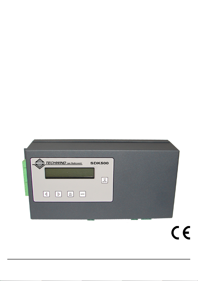
USER'S MANUAL
elevator door controller
type:
SDK-500
firmware version:
1.21.0
Read the user's manual carefully before starting to use the unit.
TechWind company reserves the right to introduce changes without prior notice.
2013.03.12
V.1.07
Page 2
User's manual for elevator door controller SDK-500
Copyright
Copyright © 2007,TechWind. All rights reserved.
This document may not be copied or otherwise reproduced, in whole or in part, except
as specifically permitted under international copyright law, without the prior
written consent from TechWind.
Disclaimer
THE INFORMATION IN THIS DOCUMENT IS SUBJECT TO CHANGE WITHOUT NOTICE.
TechWind ASSUMES NO RESPONSIBILITY FOR INACCURACIES OR OMISSIONS AND
SPECIFICALLY DISCLAIMS ANY LIABILITIES, LOSSES, OR RISKS, PERSONAL OR
OTHERWISE, INCURRED AS A CONSEQUENCE, DIRECTLY OR INDIRECTLY, OF THE
USE OR APPLICATION OF ANY OF THE CONTENTS OF THIS DOCUMENT. FOR THE
LATEST DOCUMENTATION, CONTACT YOUR LOCAL SUPPLIER OR TechWind
COMPANY.
This publication may contain examples of screen captures and reports used in daily
operations. Examples may include fictitious names of individuals and companies. Any
similarity to names and addresses of actual businesses or persons is entirely coincidental.
Trademarks and
patents
TechWind name and logo are registered trademarks of TechWind company.
SDK-500 product and logo are registered trademarks of TechWind company.
Other trade names used in this document may be trademarks or registered trademarks of the
manufacturers or vendors of the respective products.
Software license
agreement
Software and firmware supplied with products is proprietary and furnished under license and
can be used or copied only in accordance with the license terms.
THE ENCLOSED PROGRAM IS FURNISHED SUBJECT TO THE TERMS AND
CONDITIONS OF THIS AGREEMENT. RETENTION OF THE PROGRAM FOR MORE THAN
30 DAYS, OPENING OF THE SEALED WRAPPER, IF ANY, SURROUNDING THE
PROGRAM, OR USE OF THE PROGRAM IN ANY MANNER WILL BE CONSIDERED
ACCEPTANCE OF THE AGREEMENT TERMS. IF THESE TERMS ARE NOT
ACCEPTABLE, RETURN THE UNUSED PROGRAM AND ANY ACCOMPANYING
DOCUMENTATION TO TechWind FOR A FULL REFUND OF THE LICENSE FEE PAID.
Intended use Use this product only for the purpose it was designed for; refer to the data sheet and user
documentation. For the latest product information, contact your local supplier or visit us online
at www. techwind .pl
European directives The European directive “Waste Electrical and Electronic Equipment”
(WEEE) aims to minimise the impact of electrical and electronic
equipment waste on the environment and human health. To conform with
this directive, electrical equipment marked with this symbol must not be
disposed of in European public disposal systems. European users of
electrical equipment must now return end-of-life equipment for disposal.
Further information can be found on the following website:
www.recyclethis.info.
2
Page 3
User's manual for elevator door controller SDK-500
CONTENTS
1. SAFETY NOTES..........................................................................................................................................4
2. INTRODUCTION..........................................................................................................................................5
3. CONTROLLER INSTALLATION.................................................................................................................6
3.1. INSTALLATION..................................................................................................................................6
3.2. ELECTRICAL CONNECTIONS..........................................................................................................6
3.3. POWER SUPPLY...............................................................................................................................8
3.4. MOTOR...............................................................................................................................................8
3.5. ENCODER .........................................................................................................................................9
3.6. CONTROL INPUTS............................................................................................................................9
3.7. RELAY OUTPUTS ...........................................................................................................................11
3.8. EXTERNAL OPTICAL BARRIER ....................................................................................................12
3.9. INSTALL SWITCH............................................................................................................................12
3.10. OPTIONAL TERMINAL POSITION CONTACT (DOOR OPEN)...................................................13
3.11. OPTIONAL RS-485 INTERFACE ..................................................................................................14
3.12. EMERGENCY BATTERY POWER SUPPLY BUTTON................................................................14
4. CONTROLLER PROGRAMMING.............................................................................................................15
4.1. PROGRAMMING MENU..................................................................................................................15
4.2. EDITING PARAMETERS.................................................................................................................16
4.2.1. Numeric parameters................................................................................................................16
4.2.2. Switch parameters..................................................................................................................16
4.3. MENU STRUCTURE........................................................................................................................17
4.4. MENU DESCRIPTION.....................................................................................................................18
1.Doors data......................................................................................................................................18
2.Speeds ..........................................................................................................................................18
3.Calibration......................................................................................................................................19
4.Working modes...............................................................................................................................23
5.Inputs..............................................................................................................................................23
6.Outputs...........................................................................................................................................24
7.Photocell.........................................................................................................................................24
8.Access setup..................................................................................................................................25
9.Region............................................................................................................................................25
A. Default set.....................................................................................................................................25
5. MESSAGES...............................................................................................................................................26
5.1. NORMAL OPERATION....................................................................................................................26
5.2. WARNING MESSAGES ...................................................................................................................28
6. FIRST POWER-ON....................................................................................................................................29
7. RS-485 INTERFACE HANDLING.............................................................................................................30
7.1. LIST OF REGISTERS......................................................................................................................31
8. USER'S SETTINGS LIST..........................................................................................................................33
9. TECHNICAL DATA....................................................................................................................................34
3
Page 4
User's manual for elevator door controller SDK-500
Explanation of symbols used in the manual:
- This symbol denotes especially important guidelines concerning the installation and
operation of the device. Not complying with the guidelines denoted by this symbol
may cause an accident, damage or equipment destruction.
IF THE DEVICE IS NOT USED ACCORDING TO THE MANUAL THE USER IS
RESPONSIBLE FOR POSSIBLE DAMAGES.
1. SAFETY NOTES
Prior to commissioning the system read the operating instructions
thoroughly. Instructions contain important information on installation, use,
and safety of the device. Failure to follow the instructions can lead to
serious injuries or damage to the property may occur if the respective
precautions are not taken.
WARNING:
-
Only qualified staff should work on this device or in its vicinity. The staff must
thoroughly be informed about all warnings and maintenance measures
according to this operating instruction.
-
To ensure the correct and safe operation of this device, proper transport,
storage and assembly as well proper operation and professional maintenance is
required.
- TechWind disclaims
responsibility for property damage or personal injuries
resulting from installation or operation of the equipment by unprofessional or
untrained personnel or improper use thereof.
TechWind
warns that improper
installation may case serious body injuries or property damage.
- TechWind reserves the right to modify the product to improve its functionality
and quality. Always check if the version of the manual used by your or your
personnel corresponds to the version of controller being installed or operated.
- Checking for visible signs of the transportation-related damage is mandatory
before installation.
- Any unauthorised modification of hardware or software of the controller is not
permitted.
- Do not power the unit from power sources of different ratings than described in
the following chapters of this manual.
- It is mandatory to power down the whole unit prior to the controller installation.
- The entire wiring should be done and checked by the qualified installers with
the valid certification according to the electrical regulations.
4
Page 5
User's manual for elevator door controller SDK-500
- Once installation is finished all connections should be re-checked.
- Usage of the controller without calibration and without entering proper door
parameters is not allowed. The default parameters are not universal and will not
provide optimal conditions of door operation. Specifically compliance with
regulations related to the maximum kinetic energy cannot be achieved without
entering correct door characteristics
2. INTRODUCTION
SDK-500
is an electronic controller of automatic elevator door. It ensures optimum
operating conditions for doors of up to 400 kg. It was designed to work with drives fitted with
shaft encoders powered with 5V DC, which generate from 150 to 999 pulses per centimetre of
linear door motion.
Device automatically calculates door motion parameters (e.g. speed profile, acceleration and
deceleration points, acceleration values) based on the door physical characteristics (weight
and width) such as to ensure optimum operation of the drive.
Because of large value of allowable input currents, there are new menu options. Beside
parameters corresponding to door weight and door width, it is important to set correct values of
tightening force and reverse force. Incorrect settings (too high) of current value corresponding
to tightening force may cause damage to the motor.
SDK-500
menu allows for setting of the current corresponding to tightening force separately for open door and closed door positions. It is also possible to zero the tightening
force while elevator is stopped (menu option: tightening force while
{CLOSE INP.}
signal – if it
is supported by elevator's main controller).
Once the automatic calibration routine is completed, the calculated settings are stored in
non-volatile memory of the controller. The
SDK-500
controls the door drive such as to meet
the requirements of norms regulating the maximum driving force and the maximum kinetic
energy of the door. Thanks to continuous monitoring of the drive parameters the
SDK-500
can
detect increasing motion friction of the drive and alert the service person that maintenance is
required.
All important operation information is presented in a clear manner on the built-in, backlit
LCD display.
The
SDK-500
ships in a metal housing that ensures protection against mechanical
damage as well as adverse environmental conditions.
INFORMATION:
Should you require more information, or should particular problem occur which are
insufficiently described in that manual, please contact TechW ind company.
tel. (+48 58) 684 86 19-20, fax (+48 58) 684 86 17
www. techwind .pl , e-mail: biur o@ techwind .pl
5
Page 6

User's manual for elevator door controller SDK-500
3. CONTROLLER INSTAL LATION
WARNING:
• Read the basic safety requirements on page 4 prior to starting the installation.
• Ensure that the power supply network voltage corresponds to the nominal
voltage stated on the unit’s identification label.
• Power supply terminals and other parts posing hazard of electric shock must be
protected from unauthorised access
3.1. INSTALLATION
Install the controller such as to minimize the length of electrical connections between the
controller and the motor / encoder unit. Use the four mounting holes in the base of the
controller housing to secure the device in its mounting position.
Select mounting position for the controller such as to minimize the risk of inadvertent
stepping onto its housing by elevator service personnel, but to ensure easy access to LCD
display and keypad.
3.2. ELECTRICAL CONNECTIONS
WARNING:
• It is strictly required to provide good grounding of controller metal housing and
transformer cover, using separate grounding wire to appropriate grounding
terminal.
• Motor and encoder wires must be shielded, and firmly fixed to door mounting
frame in order to avoid mechanical damage to the wiring.
• The ground plane of the controller's electronics
is electrically connected
to the
housing.
Pay special attention to installation of the mains transformer. It is best to install it within
the housing of the service ride switchboard usually found on top of the car. It is also possible
to power the controller from an external DC power supply having appropriate current rating. If
complete electrical isolation of the controller from the rest of the elevator's control system is
required, use the transformer and use potential-free contacts of relays to drive the control
inputs of the controller (see fig. 3.5A)
Figure 3.1 shows all external connectors of
SDK-500
controller. Connectors of optical
barrier, relay outputs, control inputs and communication interface of RS-485 are located near
the LCD display and keyboard area.
6
Page 7
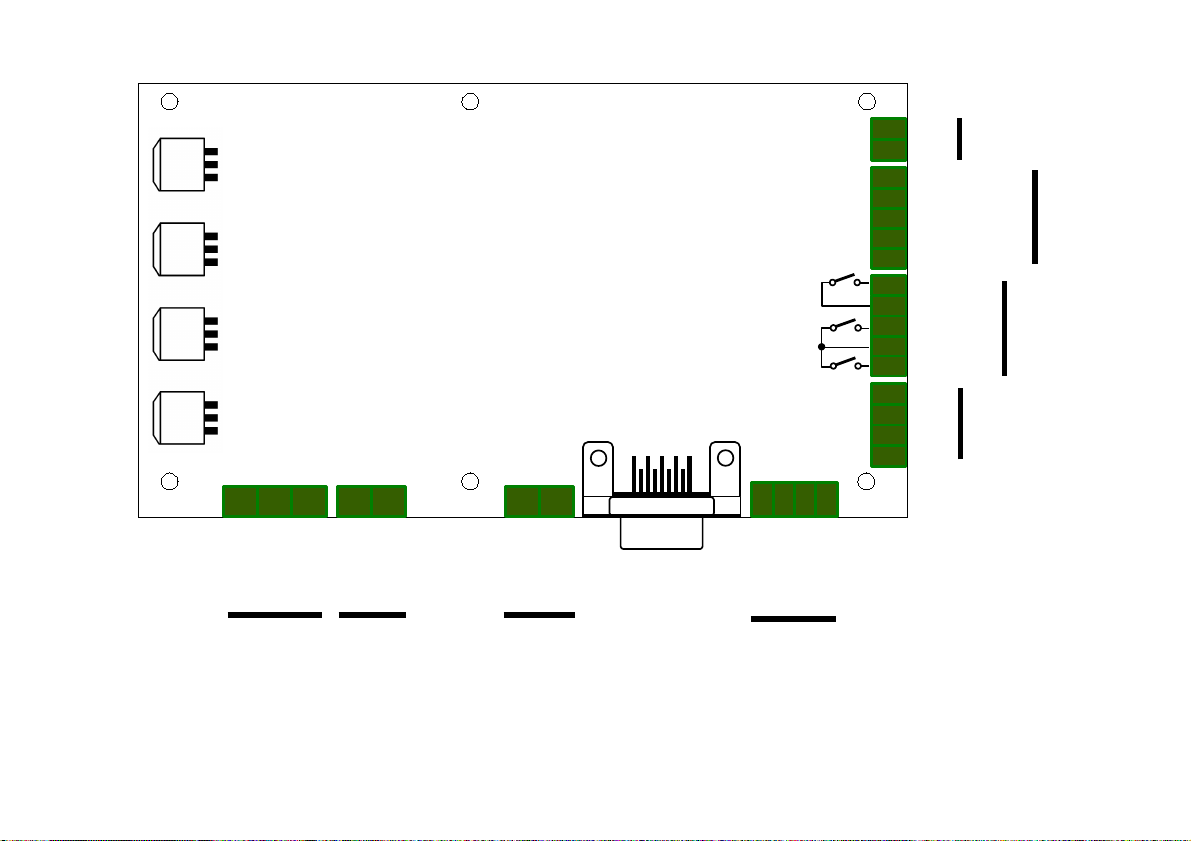
Fig. 3.1. Connectors of SDK-500 controller
J9
J8
J7
J6
J5
J4
J3J2J1
1 2
1 2 3
4
1 22 31
1
2
3
4
5
1
2
3
4
1
2
3
4
5
1
2
ENCODER
~24V AC
~24V AC
0V
+24V DC
BATTERY
AC POWER
SUPPLY
0V
SIGNAL B
SIGNAL A
+5V
ENCODER
MOTOR2
MOTOR1
EKRAN
MOTOR
0V
B A +
+5V
RS-485
OPEN INP.
CLOSE INP.
END SWITCH
INSTALL
EXT. BARRIER
POWER TO
INPUTS
BARRIER
CLOSED
COMMON
OPEN
OUTPUTS
+15V
0V
INPUTS
Page 8
User's manual for elevator door controller SDK-500
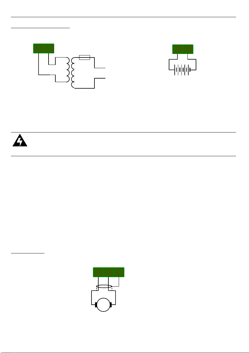
3.3. POWER SUPPLY
Fig. 3.2. Power supply connection of SDK-500 controller
Main power is supplied by a toroidal transformer - minimum 150VA and nominal output
voltage 24VAC.
•
It is necessary to protect the transformer primary winding circuit with a 2A fuse.
•
Never use transformers having idle secondary voltage higher than 27 VAC
If door operation is required also during mains failure a 24V battery of minimum 1.2Ah
capacity must be connected externally. Use of two standard 12V batteries connected in series
is possible. An automatic battery charger circuitry is a part of the controller board and is
designed to charge battery with 200 mA current, which is sufficient to keep the battery fully
charged, but will not be able to quickly charge fully discharged batteries. If main power supply
fails then LCD backlight and motor will be switched off and
SDK-500
will continue operating on
battery. When the battery voltage drops below certain threshold (19V) the controller will shut
down.
Battery connection is not mandatory and the controller can operate normally without it,
however the battery voltage read-out on the LCD will be displayed incorrectly.
3.4. MOTOR
Fig. 3.3. Motor connection of SDK-500 controller
8
J1
Motor
2 31
Battery
24V 1,2A h
- +
J3
1 2
~ 230V AC
FUSE
1 2
J2
~ 24V AC
Page 9
User's manual for elevator door controller SDK-500
The motor should be connected to
SDK-500
using shielded 2-wire cable. Make sure that
shield is connected properly to GND at one end only. Leaving shield disconnected may cause
excessive EMC noise. See chapter
First power-on
on page 29 to check the order of wire
connections.
3.5. ENCODER
A) B)
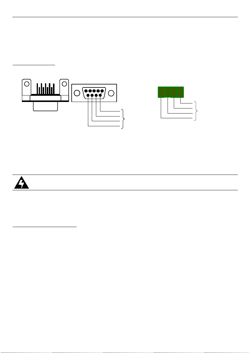
Fig. 3.4. Encoder connection of SDK-500 controller
The controller is designed to work with motors equipped with 5V quadrature encoders,
generating from 150 to 999 pulses per centimetre of door's linear movement. Typically
encoder cables are terminated with a Canon DB-9 connector. The
SDK-500
has a DB-9 socket
on board in order to facilitate fast and convenient installation. (Figure 3.4 A).
CAUTION!
Make sure that encoder signal pins match
SDK-500
encoder
connector to avoid damage to the controller.
If the encoder cable is not terminated with Canon DB-9 connector, the encoder can be
connected directly to the
SDK-500
board's screw terminals as shown in figure 3.4B.
3.6. CONTROL INPUTS
The
SDK-500
controller is equipped with two control inputs provided for compatibility with
different types of elevator controllers. Both inputs or either of them individually can be
activated from the menu of the controller. Connection alternatives are shown below.
Figures 3.5 A and B shows how to connect open/close control signals to
{CLOSE INP.}
and
{OPEN INP.}
inputs of the
SDK-500
. The control signals are generated by the main
controller of the elevator. If the elevator control system uses normally-open potential-free
contacts (e.g. relay) to control the doors they can be connected to
SDK-500
as shown in fig.
3.5A utilising the on-board voltage source of the controller. If the elevator control system uses
voltage outputs to control doors, they can be connected to
SDK-500
as shown in fig. 3.5B.
Make sure that both inputs are activated in the controller's menu.
9
J5
1
2 3 4
TO
ENCODER
+5V
SIGNAL A
SIGNAL B
0V
1
6
9
5
TO
ENCODER
0V
SIGNAL B
SIGNAL A
+5V
J4
J4
Page 10
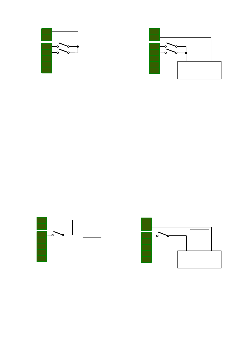
User's manual for elevator door controller SDK-500
A) B)
Fig. 3.5. Connection of the controller while using both inputs
Application of voltage to the
{OPEN INP.}
input will make
SDK-500
start the door
opening procedure. During that, until the door is fully open (until the
{OPEN}
relay output is
active) removal of the voltage from
{OPEN INP.}
input will cause the
SDK-500
to reverse the
door movement in order to close it. Removal of the voltage from
{OPEN INP.}
input after the
door has fully opened will not initiate the closing procedure and the door will remain open.
Application of voltage to the
{CLOSE INP.}
input will make
SDK-500
start the door
closing procedure. During that, until the door is fully closed (until the
{CLOSED}
relay output is
active) removal of the voltage from
{CLOSE INP.}
input will cause the
SDK-500
to reverse the
door movement in order to open it. Removal of the voltage from
{CLOSE INP.}
input after the
door has fully closed will not initiate the opening procedure and the door will remain closed.
Voltage should not be applied to both control inputs at the same time. If it is, however,
the
{CLOSE INP.}
signal wins and the
SDK-500
will behave as if only voltage was applied to
{CLOSE INP.}
input.
Figures 3.6 A and B shows how to connect the control inputs in systems where only one
output is used by the main elevator controller to control door's opening and closing. Figure
3.6A shows how to connect the
{OPEN INP.}
, input using internal
SDK-500
voltage source
and figure 3.6B shows connection in case of using voltage output on the elevator's main
controller.
A) B)
Fig. 3.6. Connection of the controller while using single {OPEN INP.} input
Make sure that ONLY one input -
{OPEN INP.}
- is activated in the menu of
SDK-500
for
this type of control. In this mode, if the voltage is applied to the
{OPEN INP.}
input,
SDK-500
will open the door and keep it open as long as the voltage remains applied. Removal of the
voltage from the
{OPEN INP.}
input will make the controller close the door.
Although the
SDK-500
can also be controlled using
{CLOSE INP.}
input only as shown in
fig. 3.7 A and B. For this purpose only the
{CLOSE INP.}
input must be activated in the
controller's menu. In this case the application of voltage to
{CLOSE INP.}
input will make the
10
J9
J8
1
2
3
4
5
1
2
OPEN INP.
CLOSE INP.
+ -
external
supply
0V
J9
J8
1
2
3
4
5
1
2
OPEN INP.
CLOSE INP.
+15V
J9
J8
1
2
3
4
5
1
2
OPEN INP. / CLOSE INP.
+15V
J9
J8
1
2
3
4
5
1
2
+ -
external
supply
0V
OPEN INP. / CLOSE INP.
Page 11
User's manual for elevator door controller SDK-500
controller to close door and keep it closed. Removal of voltage will make the controller to open
the door. Therefore this control variant is NOT RECOMMENDED for SAFETY REASONS.
Even momentary drop of voltage on the
{CLOSE INP.}
control input will immediately start door
opening procedure and, as a result, opening of safety interlock circuitry of the elevator.
A) B)
Fig. 3.7. Connection of the controller while using single {CLOSE INP.} input
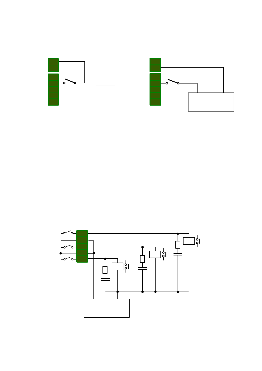
3.7. RELAY OUTPUTS
The
SDK-500
controller is equipped with three normally-open relay outputs. Two of them
(
{OPEN}
,
{CLOSED}
) indicate the door reaching the terminal positions (fully open or fully
closed). The third one (
{BARRIER}
) is used to indicate detection of an obstacle during the
door movement. It is activated both in case of the optical barrier interruption as wells as in
case of a mechanical blocking of the door movement.
Note that the relay outputs operation depends on the menu option settings. Figure 3.8
shows connection of relay outputs and inductive loads. In this case it is required to use
additional suppression circuit (typically capacitor 47nF/ min. 250VAC in series with 100R/5W
resistor), connected in parallel to relay terminals or (better) directly on the load (see figure
3.8). In consequence of using the suppression circuit, the level of generated electromagnetic
disturbances is lower, and the life of relay contacts rises.
Fig. 3.8. Relay outputs connection of SDK-500 controller
11
J9
J8
1
2
3
4
5
1
2
CLOSE INP. / OPEN INP.
+15V
J9
J8
1
2
3
4
5
1
2
CLOSE INP. / OPEN INP.
+ -
external
supply
0V
1
2
3
4
5
BARRIER
J7
+ -
external
supply
CLOSED
OPEN
Page 12
User's manual for elevator door controller SDK-500
3.8. EXTERNAL OPTICAL BARRIER
Typically optical barriers and optical detectors are connected into the main elevator
controller. In order to speed up system reaction to interruption of the barrier, connect the
barrier signal directly to
SDK-500
.
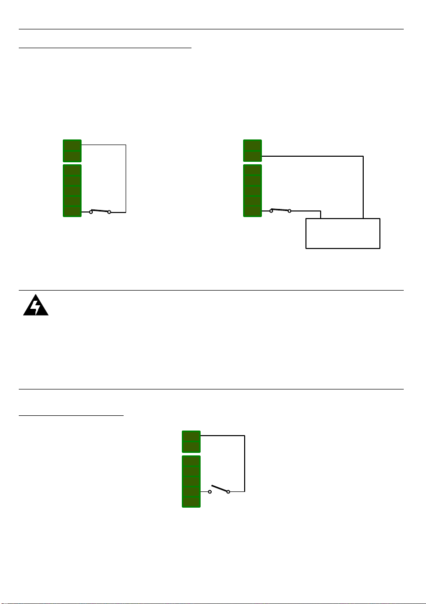
Connections of external optical barrier is shown in fig. 3.9A – using internal voltage
source of
SDK-500
and in fig. 3.9B - using external voltage from the main controller unit or
from the external optical barrier power supply.
A) B)
Fig. 3.9. External optical barrier connection
CAUTION!
•
With the barrier not interrupted the voltage must at all times be applied to the
{EXT. BARRIER}
input.
•
Remember to activate external barrier in the controller's menu (see
External
parameter description at page 24) .
•
Remember to properly select operation options of the
{BARRIER}
relay output in
the controller's menu (see
BARRIER out.
parameter description at page 24).
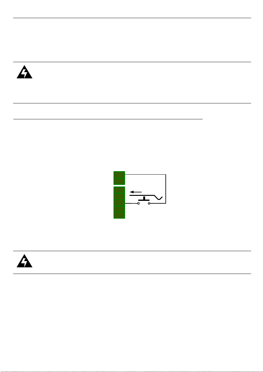
3.9. INSTALL SWITCH
Fig. 3.10. Install switch connection
12
J9
J8
1
2
3
4
5
1
2
INSTALL
+15V
J9
J8
1
2
3
4
5
1
2
EXT. BARRIER
+15V
J9
J8
1
2
3
4
5
1
2
EXT. BARRIER
+ -
external
supply
0V
Page 13
User's manual for elevator door controller SDK-500
Figure 3.10 shows connections of an Installation switch to
{INSTALL}
input of the
SDK-
500
. The Installation switch can be mounted on the housing of the
SDK-500
in order to
perform „
Installation
” procedure without the need to enter the controller's menu. If the
{INSTALL}
input is activated for a few seconds the
SDK-500
will enter the „
Installation
”
procedure (see page 19).
CAUTION!
•
Before
{INSTALL}
switch can be used, the door parameters must be entered to
the controller using menu.
•
{INSTALL}
input is enabled by default.
3.10. OPTIONAL TERMINAL POSITION CONTACT (DOOR OPEN)
Figure 3.11 shows the connection of the optional terminal position contact (NO type
contact connected to the
{END SWITCH}
input) to indicate the full opening of the door. Use of
such contact is optional as the
SDK-500
detects the terminal positions of door by detecting the
mechanical resistance at its terminal positions. This
{END SWITCH}
input is provided for
compatibility of
SDK-500
with the widest range of doors and control systems.
Fig. 3.11. Optional terminal position contact connection
CAUTION!
Remember to activate
{END SWITCH}
input in the controller's menu (see
OPEN
switch
parameter description at page 21).
13
J9
J8
1
2
3
4
5
1
2
END SWITCH
+15V
Page 14
User's manual for elevator door controller SDK-500
3.11. OPTIONAL RS-485 INTERFACE
Fig. 3.12. RS-485 interface connection of SDK-500 controller
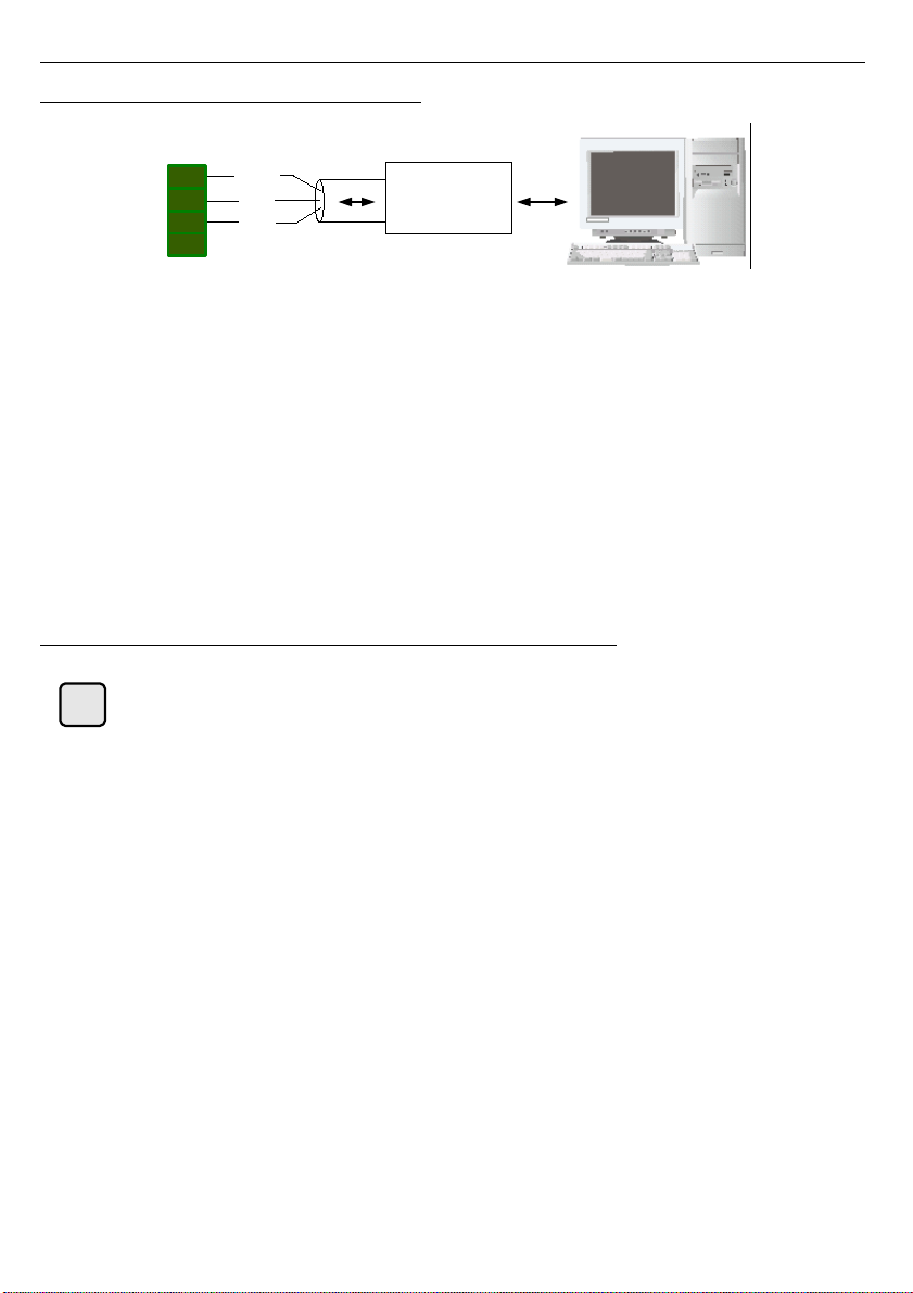
Figure 3.12 shows the connections of the RS-485 communication interface used for
connecting the
SDK-500
with other elevator controller products from TechWind. The following
functions are available via the RS-485 interface:
• open/close door control
• continuous current consumption monitoring
• momentary door speed read-out
• detailed information about current door position
• monitoring of mechanical resistance during the door movement
• controller parameters read
3.12. EMERGENCY BATTERY POWER SUPPLY BUTTON
[RUN ON BATTERY]
button allows to switch on the emergency battery
power supply.
The
SDK-500
controller is equipped with the input for back-up battery power supply
connection. It allows the controller to continue operation and open the door in the case of
mains failure. To prevent damage to the battery,
SDK-500
will automatically shut down and
disconnect the battery after battery voltage drops below certain level (19V) or door is fully
open, but not earlier than 120 sec. after last keyboard use. Every keyboard use cause to
extend run on battery by next 120 seconds. In order to resume the
SDK-500
operation on
battery power, press the
[RUN ON BATTERY]
button located on the front panel of the
controller housing (on the right side of LCD display).
14
J6
GND
Converter
RS232/485
or USB/485
B A +
1
2
3
4
RUN
ON
BATTERY
Page 15
User's manual for elevator door controller SDK-500
4. CONTROLLER PROGRAMMING
The programming menu allows the installer to set all parameters of controller operations.
The meaning of the particular parameters is described in chapter
MENU DESCRIPTION.
•
Be sure to read
First power-on
section before first powering the
SDK-500
!
•
Entering the menu is achieved by pressing and holding for 3 seconds
[ESC/MENU]
button. In case the password was entered (see
Access pass.
description at page 25), the first message will be
“Enter Password”
message.
Entering the programming menu stops the motor.
4.1. PROGRAMMING MENU
To enter main menu operator must to press and hold at least 3 sec.
[ESC/MENU]
button.
If the user password is defined (see parameter
„Access pass.“
, menu „
Access setup
”),
operator have to enter correct one before proceeding to menu options. Entering of the
passwords is similar to the edition of numeric parameters. After entering of last digit of the
password first menu position will be displayed (if the password is correct) or ”
Wrong
password!
” message otherwise.
Functions of the buttons while sub-menu and parameters choice:
Buttons
[<] [>]
allows to choose particular menu option and change value of
selected parameter. Display shows the name of selected item or its value.
Functionality of
[ENTER]
button depends on present menu position:
• If selected menu position is a parameter, pressing this button allows to
edit its value.
• If selected menu position is a sub-menu, pressing this button will enter the
sub-menu and show the first of its options.
• The
[ESC/MENU]
button allows to leave current sub-menu and abandon
changes. If pressed in the main menu it will make
SDK-500
exit the
programming mode and resume normal operation.
• Pressing and holding down
[MENU/ESC]
for 3 seconds in normal state of
the controller to enter the programming menu.
15
ESC
MENU
ENTER
Page 16
User's manual for elevator door controller SDK-500
4.2. EDITING PARAMETERS
To edit any of the programming parameters select its name using
[<] [>]
buttons and
press
[ENTER]
.
4.2.1. Numeric parameters
Numeric parameters are displayed as decimal numbers. Use buttons
[<]
,
[>]
to
increment or decrement selected (flashing) digit. Short pressing of the
[ENTER]
button moves
the selection to next digit.
Pressing
[ENTER]
at least 2 seconds (or pressing short after last digit) causes in
displaying confirmation question (message
”Save changes?”
). Select the answer (
„YES”
or
„NO”
) using
[<], [>]
buttons and confirm selection by short pressing
[ENTER]
button.
4.2.2. Switch parameters
Switch parameters can be described as a sets of values (a lists) out of which only one of
the options available on the list can be selected for the given parameter. Options of switching
parameter are selected using
[<], [>]
buttons.
Short pressing of
[ENTER]
displays confirmation question (message
”Save changes?”
).
Select the answer (
„YES”
or
„NO”
) using
[<]
,
[>]
buttons and confirm selection by short
pressing
[ENTER]
button.
Functions of buttons when editing numeric and switching parameters
While editing numeric parameters – change of current (flashing) digit. While
editing switch parameter – selection of switch parameter.
If numerical parameter is being edited, a short press of
[ENTER]
button
change edited position. A long press of
[ENTER]
button (at lest 2 sec.)
causes of display a
”Save changes?”
ask. If switch parameter is being
edited, a short press of
[ENTER]
button causes of display a
”Save
changes?”
ask. Pressing
[ENTER]
button again (while
”Save changes?”
is
displayed) the answer selected by
[<], [>]
buttons is confirmed.
Abandon entered (not confirmed) changes and go back to menu.
16
ENTER
ESC
MENU
Page 17
User's manual for elevator door controller SDK-500
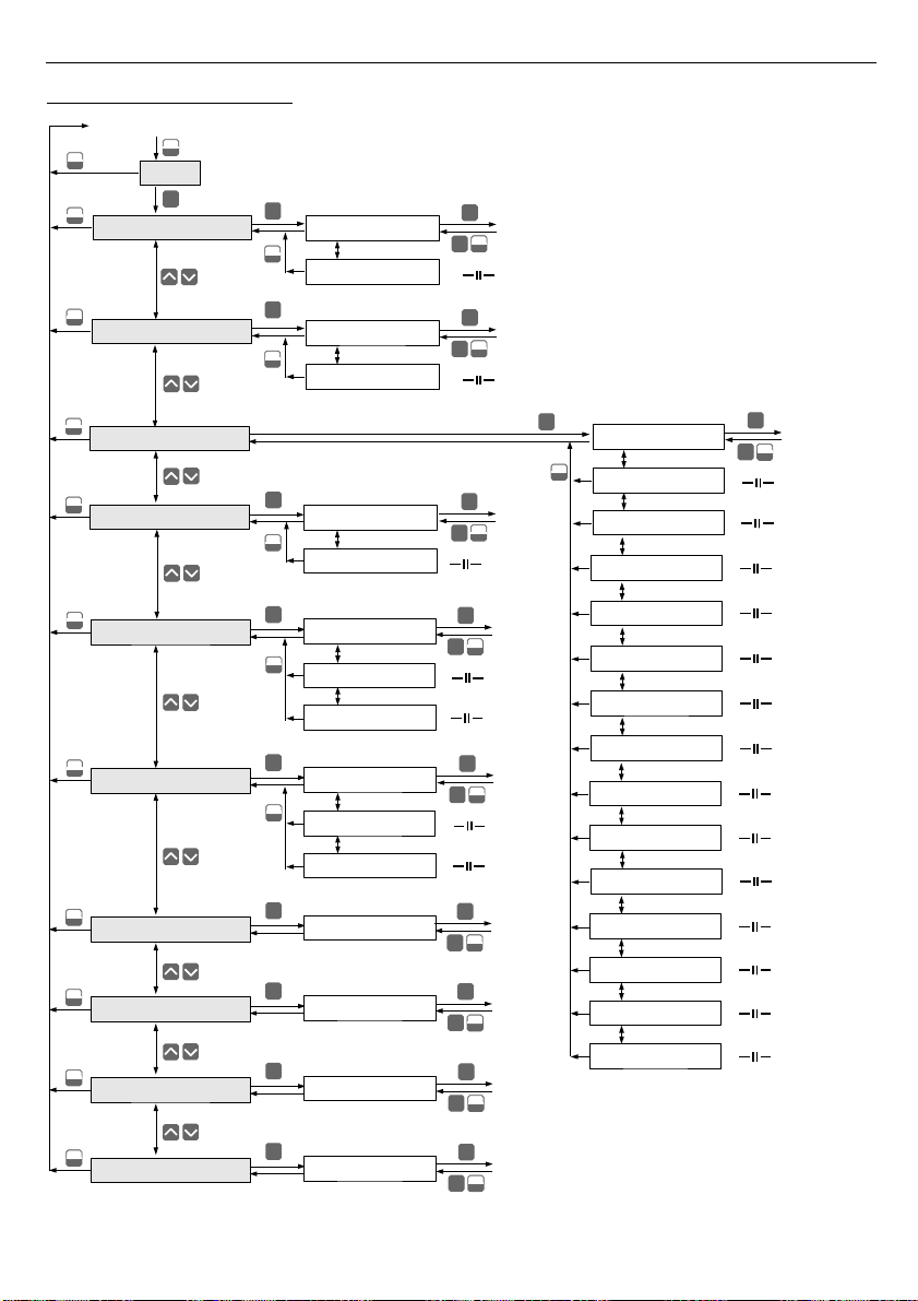
4.3. MENU STRUCTURE
17
******
6-digit user password entering (if it is different from „000000”)
Press and hold at least 2 seconds
MENU
ESC
ENTER
MENU
ESC
MENU
ESC
1. Doors data
Measurement mode
3.3. Close force
ENTER
MENU
ESC
ENTER
ENTER
1.1. Width
1.2. Weight
Parameter
edition
3.5. Open tigh.
3.7. Tighten mode
3.4. Open force
3.8. OPEN switch
3.9. Lock zone
3.6. Closed tigh.
MENU
ESC
3. Calibration
ENTER
MENU
ESC
ENTER
3.1. Installation
3.2. Init. speed
Parameter
edition
2. Speeds
MENU
ESC
MENU
ESC
ENTER
MENU
ESC
4. Working mode
ENTER
MENU
ESC
ENTER
ENTER
4.1. Driver mode
Parameter
edition
MENU
ESC
MENU
ESC
5. Inputs
MENU
ESC
5.3. INSTALL inp.
5.2. CLOSING inp
ENTER
ENTER
MENU
ESC
ENTER
5.1. OPENING inp.
Parameter
edition
MENU
ESC
8. Access setup
4.2. Door number
MENU
ESC
ENTER
MENU
ESC
ENTER
2.1. V Opening
2.2. V Closing
Parameter
edition
MENU
ESC
ENTER
3.B. Selflearning
3.C. Diagnose
3.D. Threshold
MENU
ESC
6. Outputs
MENU
ESC
6.3. BARRIER out.
6.2. CLOSED outp.
ENTER
ENTER
MENU
ESC
ENTER
6.1. OPEN output
Parameter
edition
ENTER
ENTER
MENU
ESC
ENTER
8.1. Access pass.
Parameter
edition
MENU
ESC
9. Region
ENTER
ENTER
MENU
ESC
ENTER
9.1. Language
Parameter
edition
MENU
ESC
A. Default set.
ENTER
ENTER
MENU
ESC
ENTER
A.1. Restore
Parameter
edition
MENU
ESC
7. Photocell
ENTER
ENTER
MENU
ESC
ENTER
7.1. External
Parameter
edition
3.A. Lock. speed
3.E. Pause time
3.F. Force reduc.
Page 18
User's manual for elevator door controller SDK-500
4.4. MENU DESCRIPTION
1. Doors data
1.1. Width, range: 20.0 ÷ 399.9 [ cm ]
The real (measured) path of a single-slide of door must be entered here. For single-slide
door the entire door width must be entered. For double slide door (build with two separate
parts meeting in the centre) a half of the entire door width must be entered. Entering incorrect
value will lead to incorrect calculation of the real door speed, which is necessary to stay in line
with value entered to the menu.
1.2. Weight, range: 10 ÷ 399 [ kg ]
It is mandatory to enter real door weight. It is critical to control of door's kinetic energy,
whose maximum value must not exceed 10 J.
•
CAUTION!
Entering incorrect values can lead to the faulty operation of the door
and/or can create serious risk of injuries.
•
If the door weight setting is being changed after the speed settings have been
made and a value is entered which would result in exceeding the maximum
allowable kinetic energy of the door, the controller will display "
Kinetic energy
exceeded
" message and automatically adjust maximum speed such as to
account for the new weight setting.
2. Speeds
2.1. V Opening, range: 0.10 ÷ 0.79 [ m/s ]
Required door opening speed should be entered here.
2.2. V Closing, range: 0.10 ÷ 0.79 [ m/s ]
Required door closing speed should be entered here.
Based on the entered door weight
SDK-500
automatically calculates maximum door
speed not to exceed the maximum allowed kinetic energy of the door (10J). If the
V Opening
or
V Closing
entered here is greater than the calculated maximum speed, it will be adjusted
down to prevent of exceeding the maximum value of kinetic energy.
•
If the door weight setting is changed by the installer (operator) such that the
kinetic energy calculated for speed
V Opening
or
V Closing
exceeds the
permissible value then "
Kinetic energy exceeded
", message is displayed. In
this case adjustments are made automatically to
V Opening
or
V Closing
or
both to bring the kinetic energy down to its maximum value.
•
CAUTION!
Subsequent change of door weight setting back to original value
WILL NOT
affect the
V Opening
or
V Closing
values. It is necessary to enter
required values again.
18
Page 19
User's manual for elevator door controller SDK-500
•
If the door weight setting is being changed after the speed settings have been
made and a value is entered which would result in exceeding the maximum
allowable kinetic energy of the door, the controller will display "
Kinetic energy
exceeded
" message and automatically adjust maximum speed such as to
account for the new weight setting.
3. Calibration
3.1. Installation [ execute ]
The
„
Installation”
procedure must be performed during the first power-on of the
SDK-
500
controller. The door will be driven slowly to fully closed position and then to fully open
position.
If start of
„
Installation”
procedure causes door opening it is important to stop
procedure immediately by pressing
[ESC/MENU]
button. Next switch off the
controller power supply and swap motor power supply lines –
J1.1
and
J1.2
connectors (see figure 6.1 at page 29). After changing motor power supply
connection
„Installation”
procedure must be start again.
During this movement terminal positions of the door will be identified and stored in the
controller's non-volatile memory. Then the door will be closed again. Finally, door will open and
close three times with programmed speeds and entered values of the door parameters. During
that operation an average current value will be stored in the controller's non-volatile memory
as the reference values for the door mechanical resistance.
Installation procedure should only be executed when all door parameters are correctly set in
the
SDK-500
. This procedure is set of two procedures executed in sequence:
„
Selflearning”
procedure (described at page 22) and
„
Diagnose”
procedure (described at page 22).
3.2. Init. speed (Initialisation speed), range: 5,0 ÷ 99,9 [ % ]
Percentage value of the door speed during initialisation and calibration process should be
entered here.
If value entered by user will be too high, then calibration may fail.
19
Page 20
User's manual for elevator door controller SDK-500
3.3. Close force (Closing force), range: 0.00 ÷ 6.00 [ A ]
In this menu the static door closing force is entered, expressed as the corresponding
motor current in Amperes. In order to determine it, during the calibration use a dynamometer
to find the current corresponding to the force of 150 N, which the regulations adopt as the
maximum permissible static force applied by the door to any object in its path. The
corresponding current value is treated by the controller as the absolute maximum current to be
supplied to the motor while door closing.
3.4. Open force (Opening force), range: 0.00 ÷ 6.00 [ A ]
In this menu the static door opening force is entered, expressed as the corresponding
motor current in Amperes. In order to determine it, during the calibration use a dynamometer
to find the current corresponding to the force of 150 N, which the regulations adopt as the
maximum permissible static force applied by the door to any object in its path. The
corresponding current value is treated by the controller as the absolute maximum current to be
supplied to the motor while door opening.
•
If the door encounters an obstacle in its path, the motor's current consumption
rapidly increases. If it exceeds the value set by
„
Close force” or „Open force”
parameters the controller will stop the door and reverse its motion to move it
away from the obstacle.
•
Once the door is moved away from the obstacle, the controller will attempt to
close/open the door once again. If the obstacle is still in the door's way, the
procedure will be repeated up to 5 times. If the obstacle is still in the door's way
the controller will attempt to close/open the door moving it at minimum speed. If
this attempt also fails, the controller will move the door to fully open/closed
position and wait for 20 sec. Next the closing/opening procedures starts again. If
{OPEN INP.}/{CLOSE INP.}
signals will change while attempt of
closing/opening procedure then full cycle will start again.
3.5. Open tigh. (tightening force of opened doors), range: 0.00 ÷ 1.00 [ A ]
The value of the current used to tighten door at its open positions. This value should be
determined empirically by taking into account all forces from mechanical closing elements like
springs and weights. Before changing this parameter, door should be closed. Then increase
current value carefully to cause the door moving slowly into fully open position. If door stops
during opening then continue increase current to force moving. Final current should be set to
lowest value to keep door in fully open position.
•
During current setting procedure, door speed is NOT controlled – therefore to
avoid door crash do NOT set high current values. Current value should be
increased very carefully, very slow, with visual door motion control. When door
is moving (opening), do NOT increase the current value.
•
Do not set current value greater than determined during procedure described
above. To high current value may cause motor overload, overheat and even
damage.
20
Page 21
User's manual for elevator door controller SDK-500
3.6. Closed tigh. (tightening force of closed doors), range: 0.00
÷ 1.00 [ A ]
The value of the current used to tighten door at its closed positions. This value should be
determined empirically by taking into account all forces from mechanical closing elements like
springs and weights. Before changing this parameter, door should be open. Then increase
current value carefully to cause the door moving slowly into fully closed position (and locks - if
available - will be closed). Final current value should be set to value enough to avoid door
opening and/or opening the locks, and to avoid manual door opening with ease.
•
During current setting procedure, door speed is NOT controlled – therefore to
avoid door crash do NOT set to high current value. Current value should be
increased very carefully, very slow, with visual door motion control. When door
is moving (opening), do NOT increase the current value.
•
Do not set current value greater than determined during procedure described
above. o high current value may cause motor overload, overheat and even
damage.
3.7. Tighten mode, options: [ continue / by CLOSING input ]
„Tighten mode”
setting determines when tightening force (set by
„Closed tigh.”
) is used.
Available options:
„ continue ”
- closed door is tighten continuously (power supply of motor is
always on),
„by CLOSING input”
- closed door is tighten only if voltage is provided to the
{CLOSE INP.}
input. Removal of the voltage from
{CLOSE
INP.}
input causes turning off the power supply of motor (about
5 minutes after removing voltage from
{CLOSE INP.}
input).
3.8. OPEN switch, options: [ inactive / active ]
Open switch (terminal position contact) is an additional optional switch often mounted in
sliding doors. It should activate
{END SWITCH}
input at door's fully open position (see figure
3.11 at page 13). Its usage is optional as the controller automatically detects the terminal
positions of the door by detecting mechanical resistance (by measuring the current consumed
by the motor). Open switch activation causes holding door in fully open position using
„
Open
tigh.”
parameter value (tightening force of open door).
3.9. Lock zone, range: 0.0 ÷ 29.9 [ cm ]
When door reaches fully closed position, its mechanism still continues its motion to lock it
in position. To ensure smooth door movement (especially during door opening), the lock zone
value should be set equal or greater than the real (physical) lock zone length.
•
Failure to set the lock zone properly may cause faulty operation of heavy doors
(200kg and above).
•
CAUTION!
It is important to remember that for new controllers default value of
the lock zone is equal to 4 cm. Please remember to enter the correct value. For
doors without lock zone the value should be 0.
21
Page 22
User's manual for elevator door controller SDK-500
3.A. Lock. speed, range: [ MIN, 20%, 40%, 60%, 80%, 100% ]
Required speed of the door locking should be entered here. MIN = 2.5 cm/s, speed of
door locking for option 100% depends on lock zone length.
3.B. Selflearning [ execute ]
During the
„Selflearning”
procedure the controller will move the door from the fully open
position to the fully closed position (at low speed). During such a move all pulses are
calculated and stored into the controller memory. Counted pulses represent door width.
There is no need to enter any characteristic points of the door speed profile as
SDK-500
controller calculate these points automatically adjusting all movement
parameters for optimal door functionality. All parameters are set according to
meet regulations.
3.C. Diagnose [ execute ]
It is recommended to execute the
„Diagnose”
procedure on the new installation or after
door mechanism maintenance.
SDK-500
will perform closing procedure three times and will
remember average current value during this operation which will be stored as a reference
value for
„Threshold”
parameter. During operation dirt and mechanical factors will cause
additional movement resistance which will influence the current value. As the controller is
monitoring current has a chance to detect and signal maintenance need.
3.D. Threshold, range: 0
÷ 9
9 [ % ]
This parameter defines permissible percentage by which the average current value may
be exceeded during opening+closing cycle. This threshold value is stored in memory during
door installation or periodic door maintenance visit by the installer. Maintenance value of
current
I
M
can be calculated using formula:
IM=IAV[mA] ×
100Threshold [% ]
100
where
I
AV
- average current value of opening+closing cycle stored in memory while
installation or periodical door mechanism maintenance
If average current value of opening+closing cycle is greater than maintenance value of current
I
M
then present screen of the LCD display will be shown alternately with
„Need service”
message.
3.E. Pause time, range: 0 ÷ 29 [ s ]
This parameter determines the delay of the automatic closing of the door when opened
manually.
If, during the delay "
Pause time
", the door will be opened by hand to the width
of more than 5 cm, the engine is switched off and switched back on after
a delay.
3.F. Force reduc. (Force reduction), range: 0 ÷ 99 [ % ]
This parameter determines the percentage reduction in force at the ends of the door.
22
Page 23

User's manual for elevator door controller SDK-500
4. Working modes
4.1. Driver mode, options: [ RS-485 lines / external inputs / automatic / manual ]
The
SDK-500
controller is designed as a universal unit to be used with various 3
rd
party
elevator control systems. To provide proper connection to different types of main controllers,
correct menu option must be chosen:
„ RS-485 lines ”
- systems control using RS-485 communication bus and
ModBus RTU protocol. It is required to provide proper data
transmission format and registers addresses.
„
external inputs
”
- systems control using separate
{CLOSE INP.}
and
{OPEN INP.}
inputs.
„ automatic ”
- automatic closing and opening option is used for service
purposes only. It allows for automatic opening and closing
door. Once it is selected doors are opening and closing every
5 second ignoring any external signals.
„ manual ”
- after setting this option and leaving the menu, each
[ENTER]
pressing will close and open doors alternately.
4.2. Door number, range: 0 ÷ 3
Used in multi-door installation. It corresponds to the address of the
SDK-500
controller
and is used in systems driven by RS-485 interface
ONLY
.
5. Inputs
5.1 OPENING inp. (OPENING input), options: [ inactive / active ]
Voltage controlled input. Receives signals from the main elevator controller. If
{OPEN INP.}
input is set to 'active', then signal on this input will open the door. If
{CLOSE INP.}
input (see
“
CLOSING inp.”
parameter description) is set to 'inactive', then
removing the signal will close the door.
5.2 CLOSING inp. (CLOSING input), options: [ inactive / active ]
Voltage controlled input. Receives signals from the main elevator controller. If
{CLOSE INP.}
input is set to 'active', then signal on this input will close the door. If
{OPEN INP.}
input (see
“
OPENING inp.”
parameter description) is set to 'inactive', then
removing the signal will open the door.
It is not advisable to set
{OPEN INP.}
to inactive and
{CLOSE INP.}
to active.
Such settings may cause malfunction of the door if electrical wiring of these
inputs becomes damaged.
23
Page 24

User's manual for elevator door controller SDK-500
5.3. INSTALL inp. (INSTALL input), options: [ inactive / active ]
If the menu option
”INSTALL inp.”
is set to active, then applying voltage to
{INSTALL}
input will automatically perform installation procedure (see
„Installation”
option at page 19).
6. Outputs
SDK-500
controller has 3 relay outputs (
{OPEN}, {CLOSED}, {BARRIER}
) used to feed
control signals to the elevator control system.
6.1 OPEN output
, options:
[ inactive / normal open / normal closed ]
The relay connected to the output is not controlled when this option is set to
inactive.
If
set to
normal open
the relay will be in the closed state after the full door opening. If set to
normal closed
the relay will be open after the full door opening.
6.2 CLOSED outp.
, options:
[ inactive / normal open / normal closed ]
The relay connected to the output is not controlled when this option is set to
inactive.
If
set to
normal open
the relay will be in the closed state after the full door closing. If set to
normal closed
the relay will be open after the full door closing.
6.3 BARRIER out., options: [ inactive / normal open / normal closed ]
The relay connected to the output is not controlled when this option is set to
inactive.
If
set to
normal open
the relay will be in the closed state after the the photo barrier activation or
mechanical obstacle detection on the way of the door. If set to
normal closed
the relay will be
open after the photo barrier activation or mechanical obstacle detection on the way of the door.
7. Photocell
This menu allows for sending signals from the optical barrier to the
SDK-500
. When
optical barrier is not connected to the door controller, all options must be set as inactive.
CAUTION!
Incorrect setting of the optical barrier working mode can cause
improper work, for example very slow closing after long waiting time.
7.1 External
, options:
[ inactive / transfer / active ]
This parameter defines working mode of
SDK-500
and external optical barrier connected
to
{EXT. BARRIER}
input. It is necessary to transfer optical barrier signal using normally
closed contact (see figure 3.9 at page 12). Available working modes:
„ inactive ”
-
{EXT. BARRIER}
input is inactive,
„ transfer ”
- in this mode
{EXT. BARRIER}
input signal is transferred to
{BARRIER}
output only (see
BARRIER out.
option at page
24).
SDK-500
do not process
{EXT. BARRIER}
input signal.
24
Page 25
User's manual for elevator door controller SDK-500
„ active ”
- in this mode
{EXT. BARRIER}
input signal is transferred to
{BARRIER}
output and
SDK-500
process
{EXT. BARRIER}
input signal. Activation of
{EXT. BARRIER}
input (open
contact) causes door opening immediately – regardless of
{OPEN INP.}
and
{CLOSE INP.}
input signals.
CAUTION!
The door controller retries closing door attempts when the optical
barrier signal
{EXT. BARRIER}
disappears. Optical barrier state testing and
closing retries every 3 seconds. The door controller tries to close the door 5
times. If all 5 tries are unsuccessful, controller tries once more moving the door
with minimal speed and ignoring optical barrier signals. During this operation
however the possibility of mechanical obstruction is being checked.
8. Access setup
8.1. Access pass. (Access password), range: 000000 ÷ 999999
Setting the password to 000000 allows free access to the menu. Once any other
password is selected and stored it will be asked each time the menu is started.
There is no way to recover a lost password by the user or installer. In such
event please contact TechWind for assistance
9. Region
9.1. Language, options: [ Polish, English ]
Language of the controller menu content.
SDK-500
is only capable of simultaneously having two language versions of the
menu. The default languages for the Polish market version are Polish and
English. Please contact TechWind about other language versions
A. Default set.
A.1. Restore [ execute ]
„
Restore”
command allows to return all settings to their factory defaults. The description
of the factory default settings is included in the menu described in this manual.
CAUTION!
Restoring all values to the factory defaults will overwrite all settings
including any door/drive parameters. All initialisation and calibration procedures
have to be repeated as described in
First power-on
chapter.
25
Page 26
User's manual for elevator door controller SDK-500
5. MESSAGES
CAUTION!
The last characters in either of the two lines is used for diagnostic
purposes and have following meaning:
Upper line, rightmost character:
_ (underscore) -
{OPEN INP.}
input state is low
^ -
{OPEN INP.}
input state is high
Lower line, rightmost character:
_ (underscore) -
CLOSE INP.}
input state is low
^ -
{CLOSE INP.}
input state is high
5.1. NORMAL OPERATION
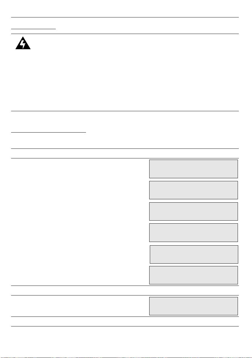
Following screens are available during the normal operation:
SCREEN 1
line1:
line2:
producer name;
door state information (initialisation, open,
closed, opening, closing, retreat) or
encoder failure message;
SCREEN 2
line1:
line2:
door speed in m/s
current value in A
SCREEN 3
26
GROS Controls
Opening < >
GROS Controls
Closing > <
GROS Controls
Initialization
GROS Controls
Encoder failure
Speed: 0.35m/s
Current: 2.15A
GROS Controls
Door is open
GROS Controls
Door is closed
Page 27
User's manual for elevator door controller SDK-500
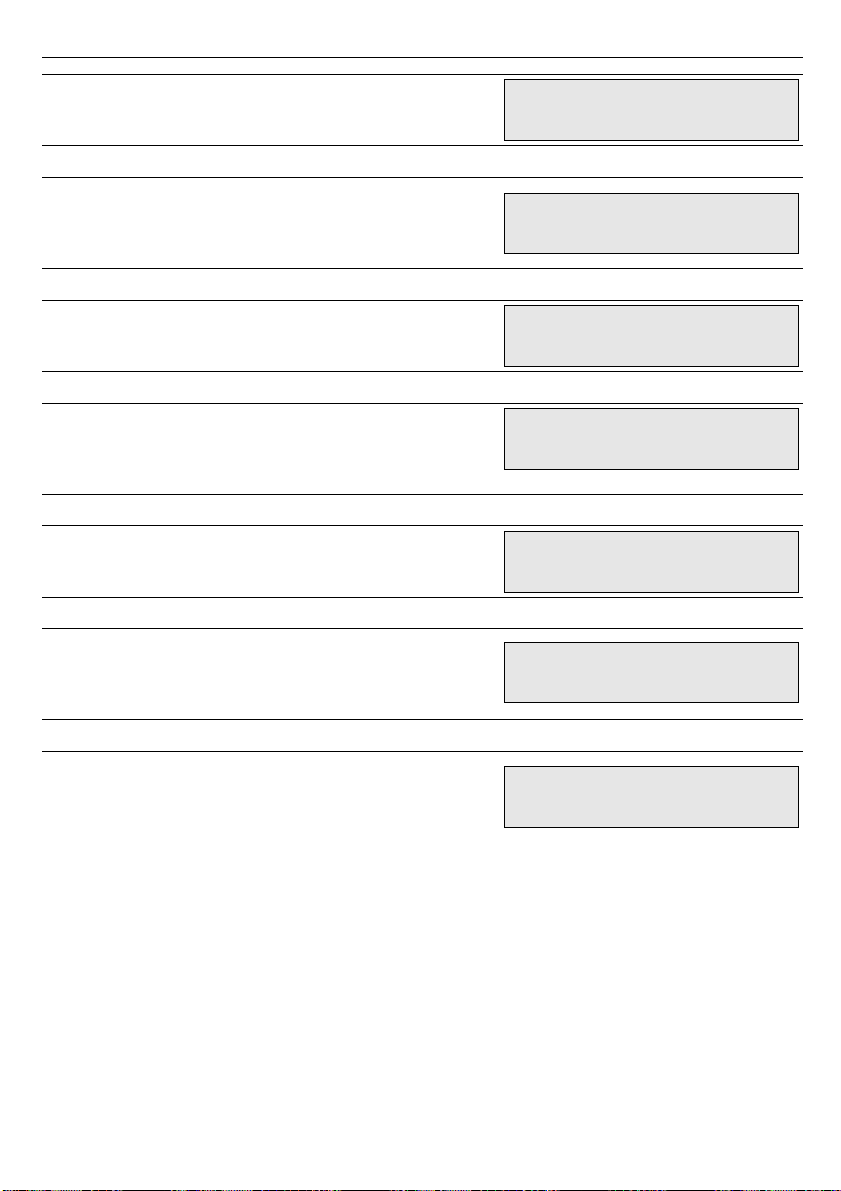
line1:
line2:
door position in cm
pulses counter value
SCREEN 4
line1:
line2:
average current value of opening+ closing
cycle in A
maximal current value of opening / closing
operation in A
SCREEN 5
line1
line2:
power supply voltage in V
battery power supply in V
SCREEN 6
line1:
line2:
tightening force (current) of closed door in
A
tightening force (current) of open door in
A
SCREEN 7
line1:
line2:
door closing current (force) in A
door opening current (force) in A
SCREEN 8
line1:
line2:
present temperature of the controller
executable components in °C
permissible temperature of the controller
executable components in °C
SCREEN 9
line1:
line2:
control inputs state, in order:
{OPEN
INP.}, {CLOSE INP.}, {END SWITCH}
,
{INSTALL}, {EXT. BARRIER}
relay outputs state, in order:
{BARRIER}
,
{CLOSED}
,
{OPEN}
and
battery power supply switch state
27
Posit.: 67cm
Counter: 30150
av.cur.: 0.50A
m. cur.: 2.10A
Power: 24.0V
Battery: 21.3V
Tight.c: 0.30A
Tight.o: 0.60A
C.force: 2.00A
O.force: 2.80A
Temper.: 26`C
T. max.: 120`C
Inputs: 00001
Outputs: 000 0
Page 28
User's manual for elevator door controller SDK-500
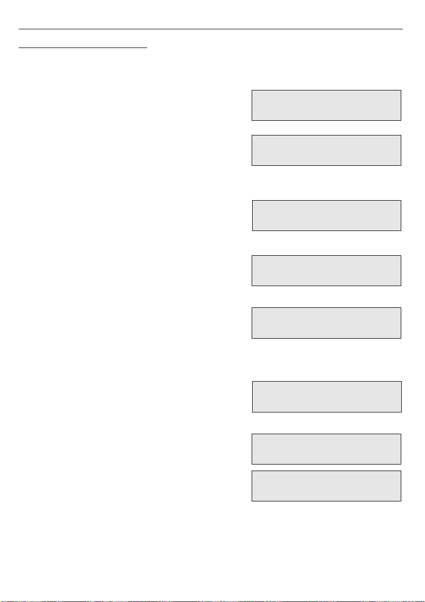
5.2. WARNING MESSAGES
While normal operation and menu parameters configuration some warning messages
described below can appear on the display.
When motor driver is overheated the message
„Exceedance of
temperature”
is displayed
alternately to current screen.
If the average current value of opening+closing
cycle is higher than maintenance current value
I
M
(described at page 22) then present screen will be
displayed alternately to the
„Need service”
message.
If the parameter
„Access pass.”
was set to the
value other then 000000, then password is required
before entering menu. There is
„Enter password”
message displayed to remind about it.
In case of wrong password entering
“Wrong
Password!”
message is displayed.
In case your password is forgotten please contact
TechWind to receive new – one use password.
Once the one use password is entered the message
„Enter new password!”
is displayed. User must
enter new password. This operation can not be
omitted.
All menu parameters have their range which can be
entered. If the value out of range is entered
„Incorrect Value”
message is displayed and edit
function is continued.
Controller checks the allowed limit of the maximum
kinetic energy, once parameter
„Weight”
,
„V opening”
or
„V closing”
are changed in the
menu. If the opening /closing speed is to high for
the door weight then speed is automatically reduced
to value corresponding to maximum allowed value
of kinetic energy. (Ekmax<10J). In such a case
message
„Exceedance of kinetic energy”
and
next
„Speed is decreased !”
28
Exceedance of
temperature
Need service
Enter Password
Wrong Password!
Enter new password!
Incorrect Value
Exceedance of
kinetic energy
Speed is
decreased !
Page 29
User's manual for elevator door controller SDK-500
6. FIRST POWER-ON
Before the first power-on, please make sure that all electrical connections are
made properly. Pay special attention to the motor and encoder connections.
See
Controller Installation
section of this manual for further details.
Having made sure that all electrical connections to the controller are made properly,
position the elevator's car such that the car's door latches on to the shaft's door. Please check
that all mechanical parts of the transmission (guides, rollers, bearings) are in good condition.
This is necessary for proper execution of the calibration procedure.
Before power up the controller slide the door into halh-open position. After power up, the
controller will display the welcome screen, containing the software version number, and
„Initialisation”
message. Immediately after controller unpacking its parameters are set by
default settings, which can be restored whenever using
„
Restore”
option in
„Default set.”
menu.
To prepare
SDK-500
for working enter the menu of the controller by holding the
[ESC/MENU]
button for 3 seconds. Once in the menu, enter all parameters characterising the
door, and its drive. See the
Controller programming
section at page 15 for details.
•
CAUTION!
Entering wrong parameters (i.e. not corresponding to actual door
and drive characteristics) may cause malfunction of the door controlled by
SDK-500
and/or may pose significant danger to persons using the door.
• The controller uses the entered value of the door's mass and controls the
speed such as to ensure that the door never exceeds the maximum allowed
kinetic energy limit.
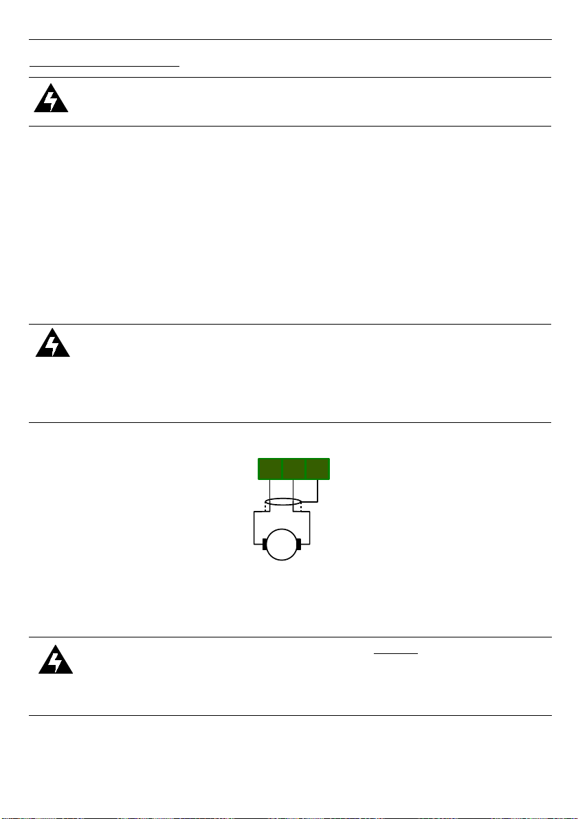
Fig. 6.1. Motor supply connector
When all parameters are set, please perform the
„
Installation”
procedure (see page
19). The door should be driven slowly to fully closed position and then to fully open position.
If start of
„
Installation”
procedure causes door opening it is important to stop
procedure immediately by pressing
[ESC/MENU]
button. Next switch off the
controller power supply and swap motor power supply lines –
J1.1
and
J1.2
connectors (see figure 6.1 at page 29). After changing motor power supply
connection
„Installation”
procedure must be start again.
During this movement terminal positions of the door will be identified and stored in the
controller's non-volatile memory. Then the door will be closed again. Finally, door will open and
close three times with programmed speeds and entered values of the door parameters. During
29
J1
Motor
2 31
Page 30
User's manual for elevator door controller SDK-500
that operation an average current value will be stored in the controller's non-volatile memory
as the reference values for the door mechanical resistance.
Once all procedures described above are finished, leave the controller's menu by
pressing the
[ESC/MENU]
button. Again, the initialisation procedure will start automatically
and the door will move to the closed position. You will see
"Door closed"
information on the
display. The door and the controller are ready for normal operation.
7. RS-485 INTERFACE HANDLING
There is optional RS-485 used for communication with
SDK-500
controller. Transmission
parameters:
–
format: 1 start bit, 8 data bits, 1 or 2 stop bits, no parity control
–
baud rate: 19200 bit/sec.,
–
protocol: Modbus RTU,
–
device address: 0x18 + N (where N means value of
“Door number”
parameter).
All device parameters are available via RS-485 interface, as HOLDING-type registers. The
registers can be read/write using following functions of Modbus RTU protocol:
–
read of registers - function 3h
–
write of registers - function 6h or 10h
• Maximum group size for 03h and 10h functions can not exceeds 16 registers (for
single frame).
• The device interprets the broadcast messages, but then do not sends the
answers.
If an error occurs while write or read of single register, then the device sends an error
code according to Modbus RTU specifications:
Error Description
01 illegal function (only functions 03h, 06h and 10h are available)
02 illegal register address
03 illegal data value (out of permissible range)
30
Page 31
User's manual for elevator door controller SDK-500
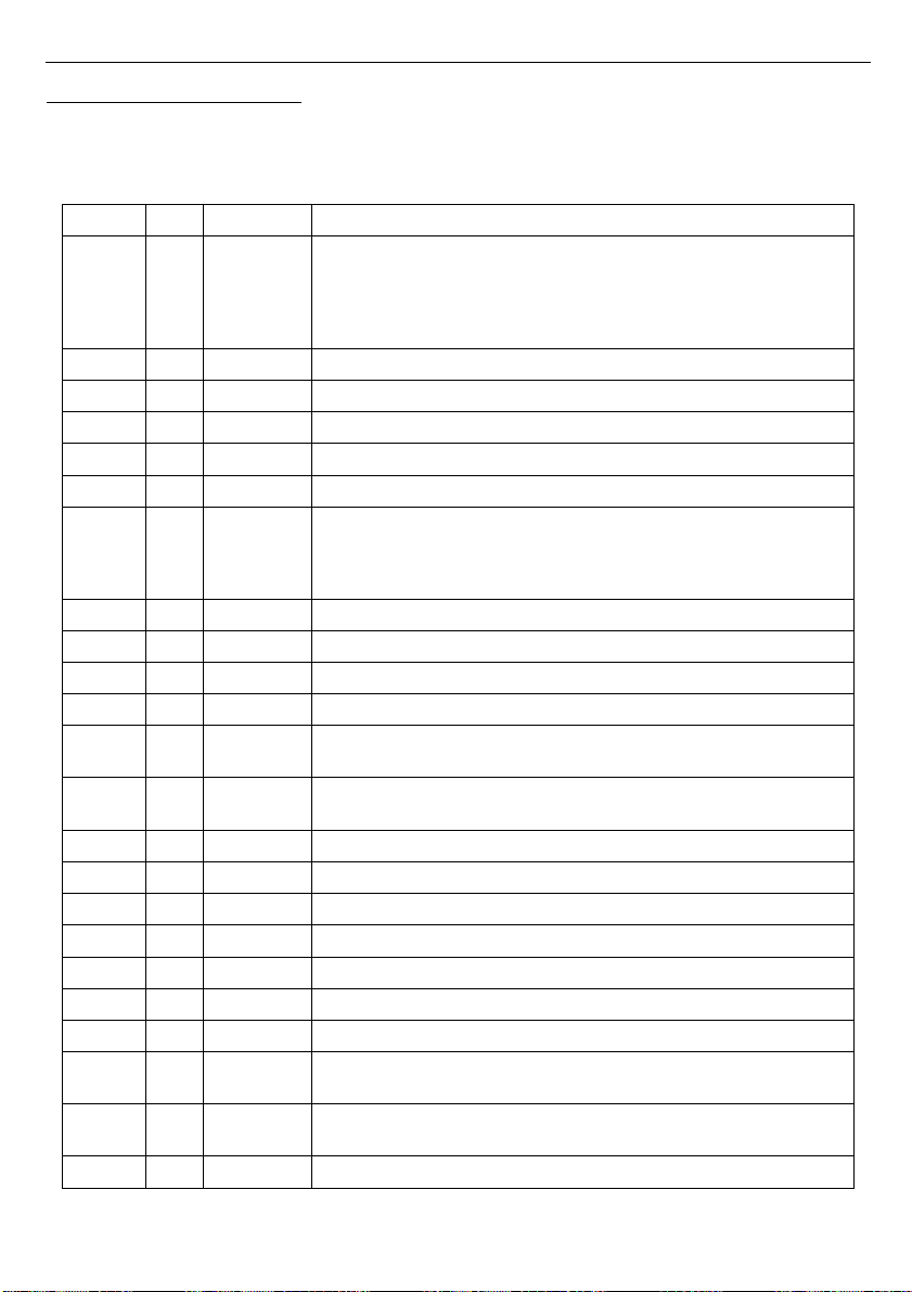
7.1. LIST OF REGISTERS
Registers described below (except 0x1004 register, which can be used for remote control
while RS-485 mode) are available for read only. While attempt to write device sends error
code 2 (illegal register address).
Register Write Range Register description
0x0001 No -
high byte:
door state:
0
– open, 1 – closed, 2 – opening, 3 – closing;
low byte:
current controller errors: 0 – no errors,
1
– barrier is active, 2 – door blockade, 3 – exceedance of kinetic
energy, 4 – encoder failure, 5 – controller overheating;
0x0002 No - Current value of motor current [mA]
0x0003 No - Current speed [mm/s]
0x0004 No - Current position [mm/10]
0x0005 No - Mean speed [mm/s]
0x0006 No - Timer for creating chart time scale [ms/50]
0x0007 No -
Control inputs state:
bit 0 – {
EXT. BARRIER.
}, bit1 – not used,
bit 2 – {
INSTALL
}, bit 3 – {
CLOSE INP.
}, bit 4 – {
OPEN INP.
},
bit 5 – {
END SWITCH
},
0x0200 No - Parameters structure version, hexadecimal
0x0201 No 0 ÷ 1 One use password state
0x0202 No 0x18 ÷ 0x1B Controller address (interface SLAVE)
0x0203 No 4 Baud rate
0x0204 No 0 ÷ 1
Permission of registers writing:
0
– writing prohibited ; 1 - writing permitted
0x0205 No 0 ÷ 99
Maximum delay between received messages: 0 – no control;
1 ÷ 99
- Maximum delay expressed in seconds
0x0206 No 0 ÷ 5 Additional delay of answer transmission
0x0207 No 0000 ÷ 6000
„Open force” parameter in „Calibration” menu, in [mA]
0x0208 No 0000 ÷ 6000 „Close force” parameter in „Calibration” menu, in [mA]
0x0209 No 0 ÷ 99
„Threshold” parameter in „Calibration” menu, in [%]
0x020A No 0 ÷ 999 Average current value of normal motor operation in [mA]
0x020B No 0 ÷ 1000
„Open tigh.” parameter in „Calibration” menu, w [mA]
0x020C No 0 ÷ 1000 „Closed tigh.” parameter in „Calibration” menu, w [mA]
0x020D No 0 ÷ 1
„Tighten mode” parameter in „Calibration” menu:
0 - continue; 1 - driven by CLOSING input
0x020E No 0 ÷ 3
„Driver mode” parameter in „Working mode” menu:
0
– RS-485 lines; 1 - external inputs; 2 - automatic; 3 - manual
0x020F No 0 ÷ 3
„Door number” parameter in „Working mode” menu:
31
Page 32
User's manual for elevator door controller SDK-500
Register Write Range Register description
0x0210 No - Door width in pulses, high byte
0x0211 No - Door width in pulses, low byte
0x0212 No 200 ÷ 3999
„Width” parameter in „Doors data” menu, in [mm]
0x0213 No 10 ÷ 399 „Weight” parameter in „Doors data” menu, in [kg]
0x0214 No 0 ÷ 79
„V opening” parameter in „Speeds” menu, in [cm/s]
0x0215 No 0 ÷ 79 „V closing” parameter in „Speeds” menu, in [cm/s]
0x0216 No 50 ÷ 999
„Init. speed ” parameter in „Calibration” menu, in [0.1%]
0x0217 No - Acceleration/deceleration speed of door opening
0x0218 No - Acceleration/deceleration speed of door closing
0x0219 No - Start point of deceleration while opening in [mm]
0x021A No - Start point of deceleration while closing in [mm]
0x021B No 0 ÷ 299 „Lock zone” parameter in „Calibration” menu, in [mm]
0x021C No 0 ÷ 1
„OPENING inp.” parameter in „Inputs” menu:
0
– inactive; 1 - active;
0x021D No 0 ÷ 1
„CLOSING inp.” parameter in „Inputs” menu:
0
– inactive; 1 - active;
0x021E No 0 ÷ 1
„OPEN switch” parameter in „Calibration” menu:
0
– inactive; 1 - active;
0x021F No 0 ÷ 2
„OPEN output” parameter in „Outputs” menu:
0
– inactive; 1 - normal open; 2 - normal closed
0x0220 No 0 ÷ 2
„CLOSED outp.” parameter in „Outputs” menu:
0 –
inactive; 1 - normal open; 2 - normal closed
0x0221 No 0 ÷ 2
„BARRIER out.” parameter in „Outputs” menu:
0
– inactive; 1 - normal open; 2 - normal closed
0x0222 No 0 ÷ 2
„External” parameter in „Photocell” menu:
0
– inactive; 1 – transfer; 2 - active
0x0227 No 0 ÷ 1
„INSTALL inp.” parameter in „Inputs” menu:
0
– inactive; 1 - active;
0x0228 No - Additional input (not used)
0x0229 No 0 ÷ 1
„Language” parameter in „Region” menu:
0
– Polish; 1 - English;
0x022A No 0 ÷ 5
„Lock. speed” parameter in „Calibration” menu:
0
– MIN.; 1 – 20% … 5 – 100%
0x022B No 0 ÷ 99
„Force reduc.” parameter in „Calibration” menu, in [%]
0x1004 Yes see desc.
Write only register
, allows to door control while RS-485 mode:
0
– open,
0x100
– close,
32
Page 33
User's manual for elevator door controller SDK-500
8. USER'S SETTINGS LIST
Parameter Description Default value User's value
Desc.
page
Parameters of “1. Doors data” menu
1.1 Width Door width 90,0 cm 18
1.2. Weight Door weight 100 kg 18
Parameters of “2. Speeds” menu
2.1. V Opening Door opening speed 0,35 m/s 18
2.2. V Closing Door closing speed 0,35 m/s 18
Parameters of “3. Calibration” menu
3.2. Init. speed Initialisation and calibration speed 50,0 % 19
3.3. Close force Closing force 2,00 A 20
3.4. Open force Opening force 2,80 A 20
3.5. Open tigh. tightening force of open door 0,60 A 20
3.6. Closed tigh. tightening force of closed door 0,30 A 21
3.7. Tighten mode Condition of using tightening force of closed door continue 21
3.8. OPEN switch End switch (terminal position contact) activation inactive 21
3.9. Lock zone Lock zone length 4,0 cm 21
3.A. Lock. speed Locking speed MIN (2.5 cm/s) 21
3.C. Threshold
Permissible percentage exceedance of the average
current value of opening+closing cycle
35 % 22
3.E. Pause time Delay of the automatic closing of the door 10 s 22
3.F. Force reduc. Force reduction at the ends of the door 50 % 22
Parameters of “4. Working mode” menu
4.1. Driver mode Device control mode external inputs 23
4.2. Door number Option used while remote control 0 23
Parameters of “5. Inputs” menu
5.1. OPENING inp. {OPEN INP.} input activation active 23
5.2. CLOSING inp. {CLOSE INP.} input activation active 23
5.3. INSTALL inp. {INSTALL} input activation active 24
Parameters of “6. Outputs” menu
6.1. OPEN output {OPEN} output operation mode normal open 24
6.2. CLOSED outp. {CLOSED} output operation mode normal open 24
6.3. BARRIER out. {BARRIER} output operation mode normal open 24
Parameters of “7. Photocell” menu
7.1. External {EXT. BARRIER} input operation mode inactive 24
Parameters of “9. Region” menu
9.1. Language Language of menu content polish 25
33
Page 34
User's manual for elevator door controller SDK-500
9. TECHNICAL DATA
Power supply voltage 22...24...38V DC; 22V...24...27V AC
Power consumption max. 160 VA
Current value of motor control max. 7A
Encoder input frequency max. 40 kHz
PWM carrier frequency 7200 Hz
Control inputs
high logic level:
low logic level:
high level active
7...24V...max.35V DC
0...2V DC
Relay outputs
NO contacts, 1A 30V DC / 1A 250V AC (cos ϕ = 1)
Power supply output for control inputs
and external devices
15V DC ±10% / max. 100 mA, stabilized
Communication interface (option) RS 485, 8N1 and 8N2, Modbus RTU, not separated
Baud rate 19200 bit/sec.
Display LCD alphanumeric, 2 x 16 characters, backlit
Data memory non-volatile memory, EEPROM type
Protection level IP20 (if DB9 encoder connector put)
Housing metal
Housing dimensions 240 x 140 x 53 mm
Operating temperature 0°C do +50°C
Storage temperature -10°C do +70°C
Humidity 5% do 90% no condensation
Altitude up to 2000 meters above sea level
Screws tightening max. torque 0,5 Nm
Max. connection leads diameter
2,5 mm2/power supply and motor connectors
1 mm2/control input/output connectors
34
Page 35

User's manual for elevator door controller SDK-500
35
Page 36

TechWind Sp. z o.o.
Miszewko Dąbrowa 6
PL – 80-297 Banino k/Gdańska, Poland
tel. : (+48 58) 684 86 19-20 , fax: (+48 58) 684 86 17
http://www.techwind.pl, e-mail: [email protected]
 Loading...