

Page 1

Techwell,Inc. TW8816 Evaluation Board User’s Manual
TW8827
Evaluation Board
User’s Manual
(Rev 1.00)
Techwell, Inc.
408 E. Plumeria Drive
San Jose, CA 95134
URL http://www.techwellinc.com
Disclaimer
This document provides technical information for the user. Techwell, Inc. reserves the right to modify the
information in this document as necessary. The customer should make sure that they have the most recent data
sheet version. Techwell Inc. holds no responsibility for any errors that may appear in this document. Customers
should take appropriate action to ensure their use of the products does not infringe upon any patents. Techwell
Inc. respects valid patent rights of third parties and does not infringe upon or assist others to infringe upon such
rights.
Version 1.00 9/25/2007
Page 2

Techwell,Inc. TW8816 Evaluation Board User’s Manual
Document Revision History
Version Date Notes By
-
Version 1.00 9/25/2007
Page 3

Techwell,Inc. TW8816 Evaluation Board User’s Manual
TABLE OF CONTENT
1. OVERVIEW OF TW8816 .............................................................................................................................. 4
2. EVALUATION BOARD .................................................................................................................................. 5
3. POWER........................................................................................................................................................... 6
4. ANALOG/DIGITAL VIDEO INPUT INTERFACE ......................................................................................... 7
5. LCD PANEL CONNECTOR INTERFACES ................................................................................................. 7
6. BUILT-IN MICROCONTROLLER INTERFACE............................................................................................ 9
7. EXTERNAL MICROCONTROLLER................................................ERROR! BOOKMARK NOT DEFINED.
8. DIP-SWITCH SETTINGS ON THE MAIN BOARD ......................ERROR! BOOKMARK NOT DEFINED.
9. OPERATION KEYS ..................................................................................................................................... 10
10. CONTROLLING THE TW8816 ................................................................................................................... 10
11. USING HYPERTERMINAL...........................................................................................................................11
12. USING TW-TERMINAL2............................................................................................................................ 15
Version 1.00 9/25/2007
Page 4
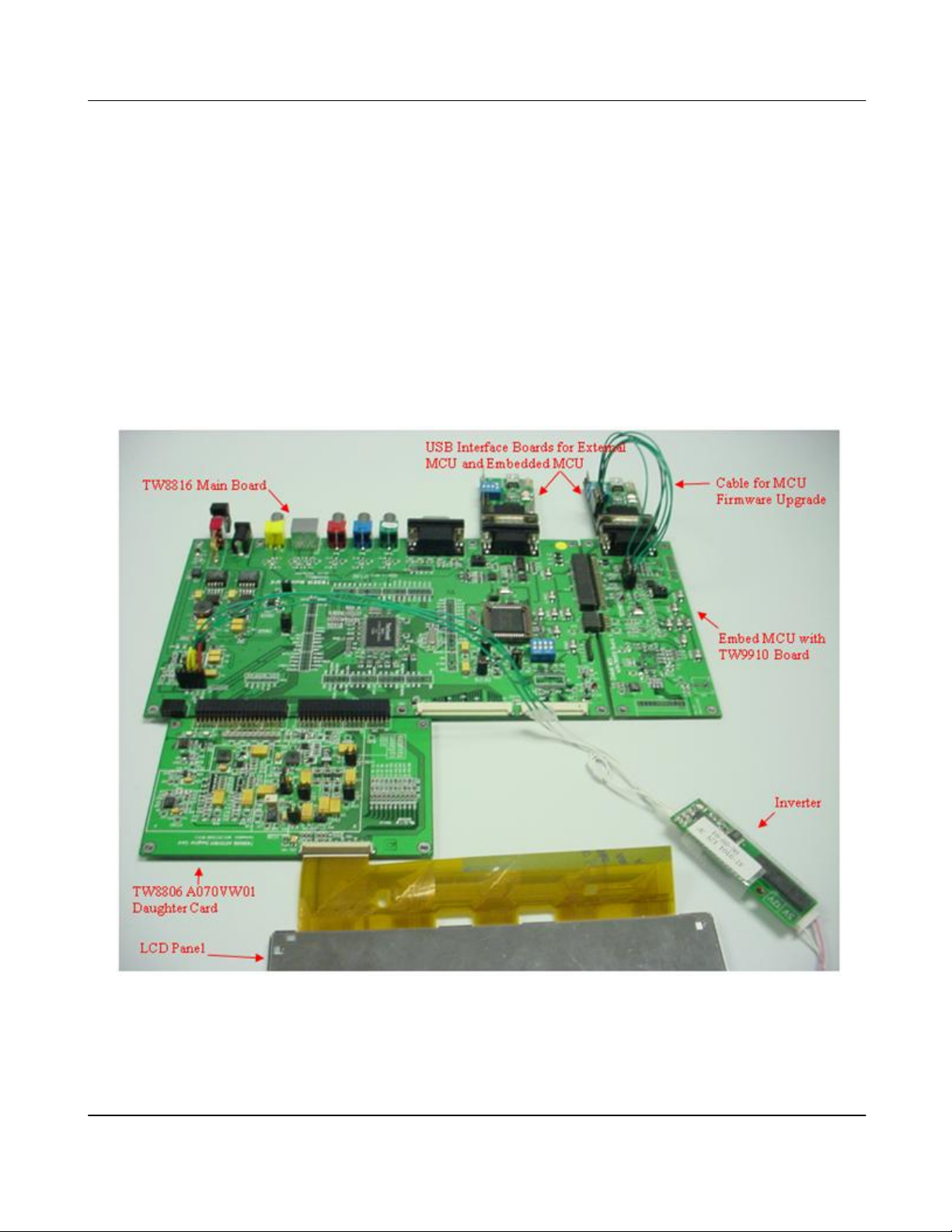
Techwell,Inc. TW8816 Evaluation Board User’s Manual
1. Overview of TW8827
TW8816 incorporates all the features in a single package for multi-purpose PC display and
LCD/TV systems. With a NTSC/PAL/SECAM TV decoder, it contains all the logics required to
convert standard TV, DTV, and PC monitor signals to the digital control and data signals to drive
various TFT panel types, and it supports resolution up to WXGA. CVBS, Analog YPbPr, and Svideo input allow direct connection to DVD and HDTV sources. Digital TTL YCbCr and RGB inputs
allow digital TV or digital VGA monitor signals to be input for display on the same LCD display
panel.
Techwell's TW8816 is an enhanced version of the TW88, TW8800, TW8801, TW8802, TW8803,
TW8804, and TW8806 flat panel TV/monitor controller. Primary enhancements include: Built-in
Microcontroller, CCFL controller, Digital Video interface, Power sequence control, Multi-window
programmable On Screen Display, 4H Comb Filter, charge pump booster, downscaling to QVGA
output resolution, internal de-interlacing engine, 3 ADCs with clamping engine. TW8816 can also
generate the control-timing signal, TCON, on-chip for non-TCON panel support.
Version 1.00 9/25/2007
Page 5
Techwell,Inc. TW8816 Evaluation Board User’s Manual
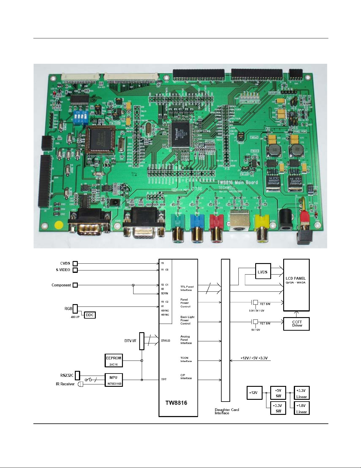
2. Evaluation Board
Version 1.00 9/25/2007
Page 6
Techwell,Inc. TW8816 Evaluation Board User’s Manual
3. Power
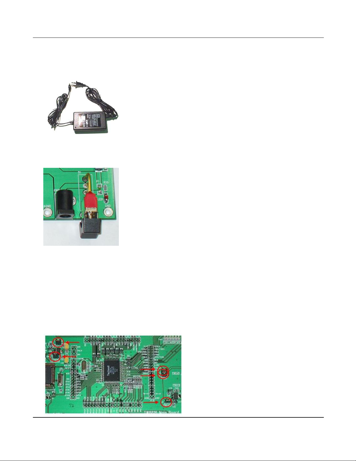
The evaluation board is provided with a DC power adapter. Typically, a 9V 1.6A power supply is
provided in the kit, but depending on the LCD module, a higher voltage and higher current DC
adapter such as a 12V 4A power supply may be used.
After properly plugging in the power adapter, the evaluation board may be switched “ON” by using
the red SPDT Toggle switch (S1) on the board. At this time, LED1 should turn on.
There are jumpers on the board that connects the power to TW8816. They should be set as
follow:
Jumper Option
J1 Installed
J2 Installed
J3 Installed
J4 Installed
J5 Installed
Version 1.00 9/25/2007
Page 7
Techwell,Inc. TW8816 Evaluation Board User’s Manual
4. Analog/Digital Video Input Interface
A video source is required to observe video output on the LCD screen controlled by TW8816.
There are various video sources that could be used with the connectors and interfaces that are
available. Selection of the input may be done by a software application or by pressing the “mode”
button of the operation keys on the main board or “Embed microcontroller board.” If there are no
PC input signals, the input selection will default to CVBS. Details of the operation of the video
input interface may vary depending on the firmware.
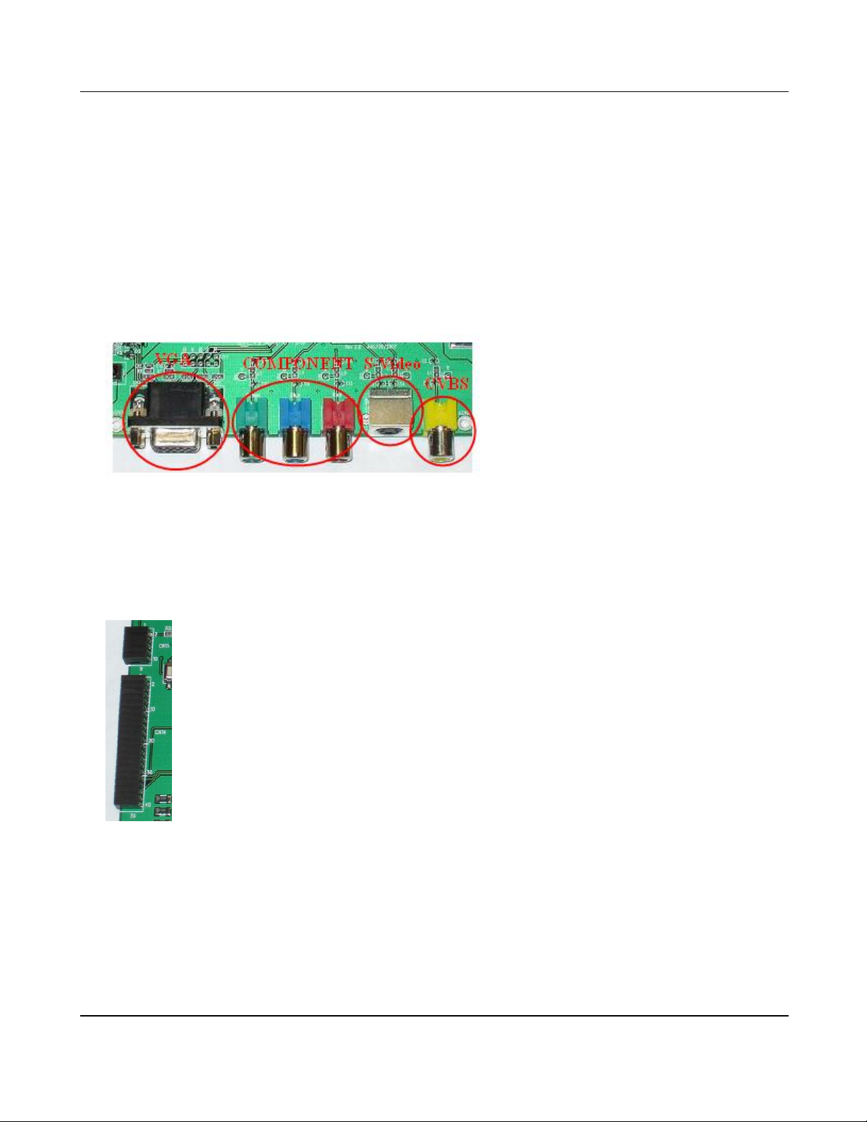
a. Analog Video Input Connectors
- S-Video
- CVBS
b. Digital Video Input Interface
- Digital video input to the TW8816 are available via the “DTV/MCU Daughter Card I/F” interface
connector CN14. It allows connection to 24-bit RGB or 8/16/24-bit YCbCr up to 108MHz, and
both interlaced and progressive ITU-656 sources are supported. On the daughter card, CVBS
input to the TW9910 is output as digital video connected to TW8816.
5. LCD Panel Connector Interfaces
Version 1.00 9/25/2007
Page 8
Techwell,Inc. TW8816 Evaluation Board User’s Manual
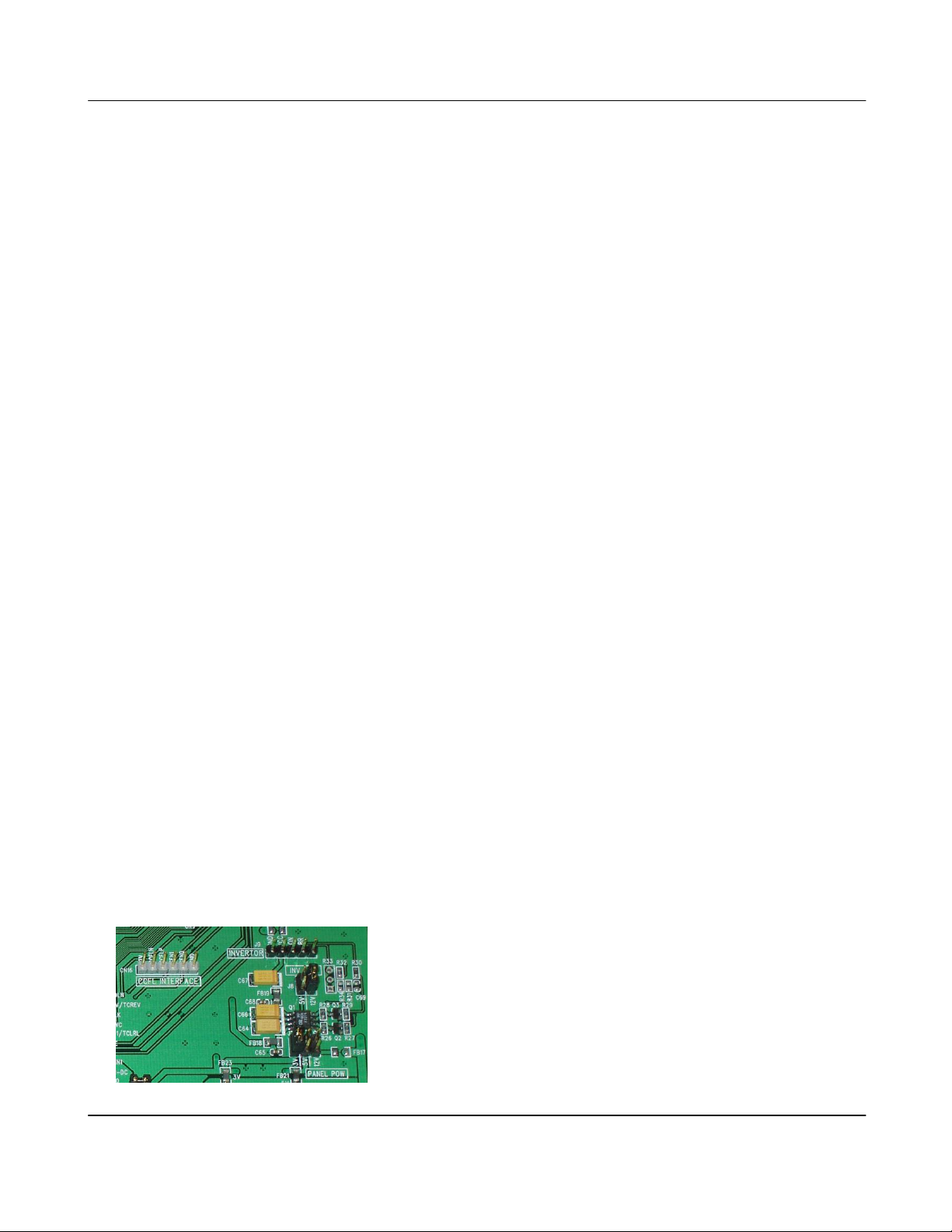
a. Panel Power Selection (J7)
The LCD panel power supply voltage can be selected with jumper J7. Please do not install more
than one jumper at once as this would damage the power supply on the evaluation board.
Voltage Jumper Position
3.3V 5:6
5V 3:4
12V 1:2 (FB17 is not installed and 12V is not available by default)
b. Inverter power Selection (J8)
The Inverter power supply voltage can be selected with jumper J8. Please do not install more
than one jumper at once as this would damage the power supply on the evaluation board.
Voltage Jumper Position
5V 3:4
12V 1:2
c. Inverter Interface (J9)
The J9 headers are used to provide power to an inverter for the LCD back light.
Pin Description Pin Description
1 GND 4 Brightness
2 VCC ( set by J8) 5 NC
3 On/Off
d. CCFL Controller Interface (CN16)
CN16 is available for the “Embed backlight controller board” connection to use the built-in CCFL
controller. This reduces the need of an external inverter used with J9. Note that if the CCFL
controller is used, the charge pump CP0 may not be used; thus, Part A of “TW8806B A070VW01
Daughter Card” cannot be connected. Also, please make sure that the firmware support CCFL
and that the CCFL interface is properly configured before using it. Incorrect configuration may
cause damage to the backlight controller board.
Pin Description Pin Description
1 12V 4 SEN1
2 CCFLN 5 SEN2
3 CCFLP 6 Ground
e. LCD Panel Connections
Version 1.00 9/25/2007
Page 9
Techwell,Inc. TW8816 Evaluation Board User’s Manual
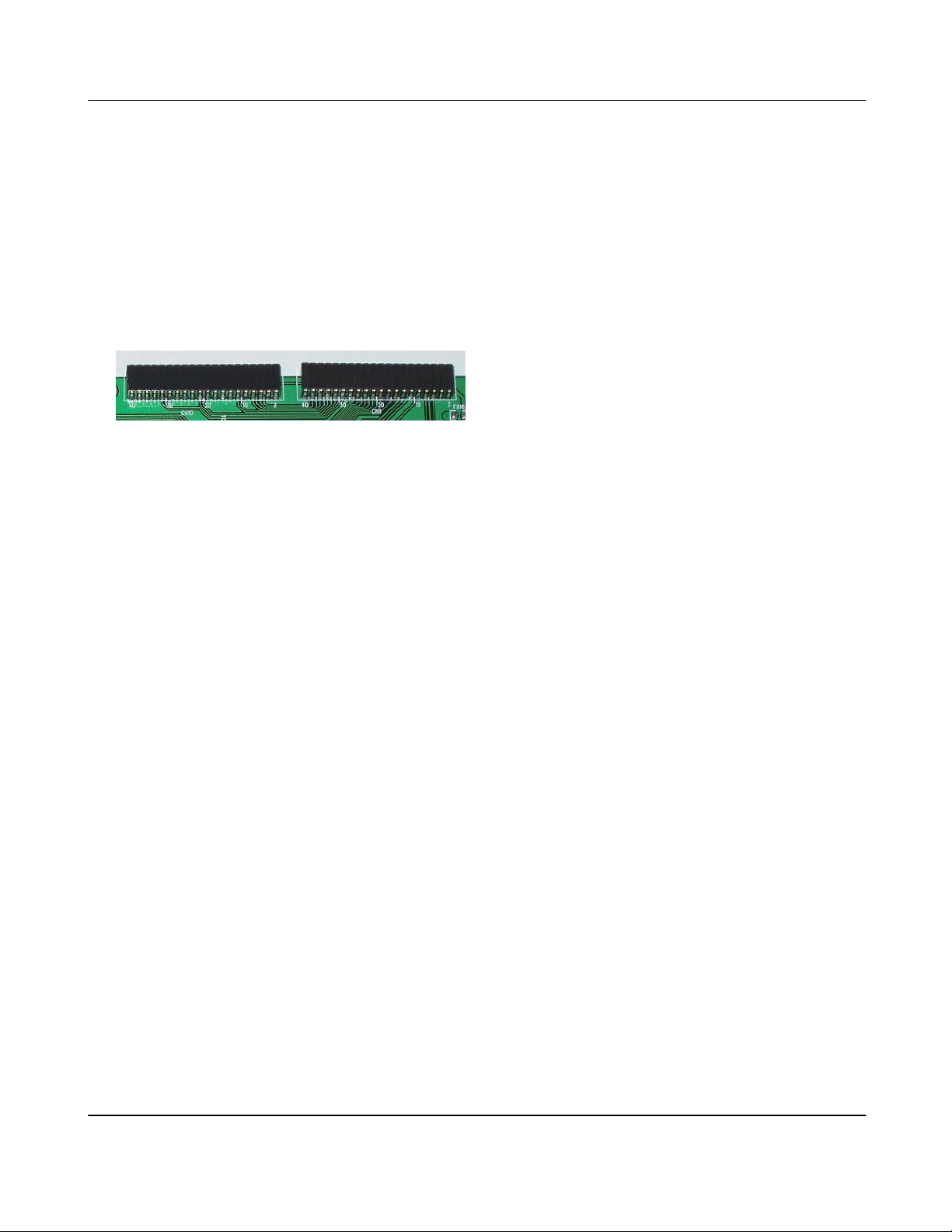
Different kinds of LCD panels usually require their specific connectors. Since there are no
standard connectors, the evaluation board has generic interfaces which are 8bits per color single
pixel LVDS, 6bit per colors single pixel TTL, and 8bits per color single pixel output pins for the
daughter boards. If the board was not provided with a proper cable for your panel, you need to
build a cable yourself.
LCD panel interfaces
- Interface for Custom Made Panel Card
Reference : CN9/CN10
Part number : PPPN202FJFN
Matching socket :PRPN202PARN
CN9
Pin Description Pin Description Pin Description
1 VCC12 (NC) 15 GND 28 TCLP
2 VCC5 16 GPIO 0 29 FPB00/TCSPR
3 VCC3 17 GPIO 1/TCLRL 30 FPB01/TRSPB
4 VCC3 18 GPIO 2/TRUDL 31 FPG00/CP1+
5 AGND 19 GPIO 1/TCLRL 32 FPG01/CP16 ROUT 20 FPBIAS 33 FPR00/CP0+
7 GOUT 21 FPPWC 34 FPR01/CP08 BOUT 22 FPPWM 35 FPHS/TCSPL
9 AGND 23 TRCLK 36 FPDE/TROE
10 AGND 24 GPIO 2/TRUDL 37 FPCLK/TCCLK
11 SEN0 25 TCINV/TCREV 38 FPVS/TRSPT
12 SEN1 26 TCPOLP 39 GND
13 COM_OUT 27 TCPOLN 40 GND
14 GND
6. Built-in Microcontroller Interface
The evaluation board has connectors on the left side of the board with reference CN14 and CN15.
These connectors may be used with the “Embed MCU with TW9910 daughter card” to utilize the
built-in microcontroller and the shared digital video interface available on the TW8816.
The built-in microcontroller may be used with the daughter card and the appropriate firmware.
Some of the features are:
- Operation Keys ( 8 keys )
- GPIOs
- Remocon IR Receiver
- UART
Version 1.00 9/25/2007
Page 10
Techwell,Inc. TW8816 Evaluation Board User’s Manual
- SPI ( SPI EEPROM available for internal microcontroller firmware )
- TW8816 as I2C Master
- Internal microcontroller will not be initialized by “RESET while pressing MENU KEY”
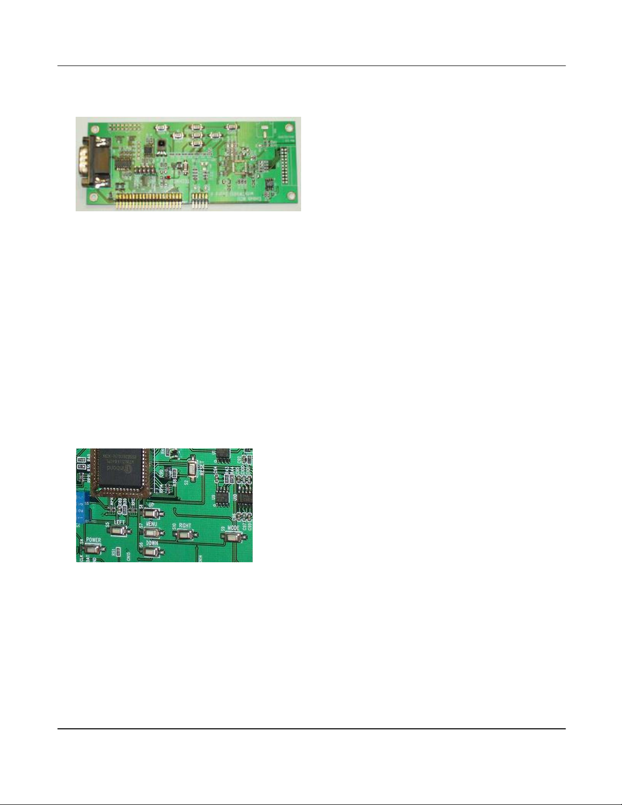
8. Operation Keys
There are 8 operation keys. Keys are shown with the Built-in and External microcontrollers.
Button Function
POWER Power On/Off
MENU Display OSD Menu On/Off
UP Menu Up
DOWN Menu Down
LEFT Move to Up Menu / Decrease Menu Item Value / Volume Down
RIGHT Select / Increase Menu Item Value / Volume Up
MODE Change Input Mode
RESET Reset the system
9. Controlling the TW8816
There are various ways to control the operation of TW8816 on the evaluation board. An RS-232
Null modem cable can be used directly from a PC to the RS-232 connector or a USB connection to
the USB Interface board for RS-232, I2C, and SPI communication. The USB Interface board is
an adapter that can be used with the evaluation board, and it also has an I2C interface ( USB-toI2C ) that may be used with customer’s board. Using the USB Interface board is recommended.
Via the USB or the RS-232 of the PC, basic commands can be used in the HyperTerminal or the
recommended sample application called TW_terminal2 provided with the evaluation kit.
Version 1.00 9/25/2007
Page 11
Techwell,Inc. TW8816 Evaluation Board User’s Manual
10. Using HyperTerminal
The Hyperterminal can only be used to access I2C registers of the TW8816 using basic
commands, send text file, and upgrade firmware of the external microcontroller.
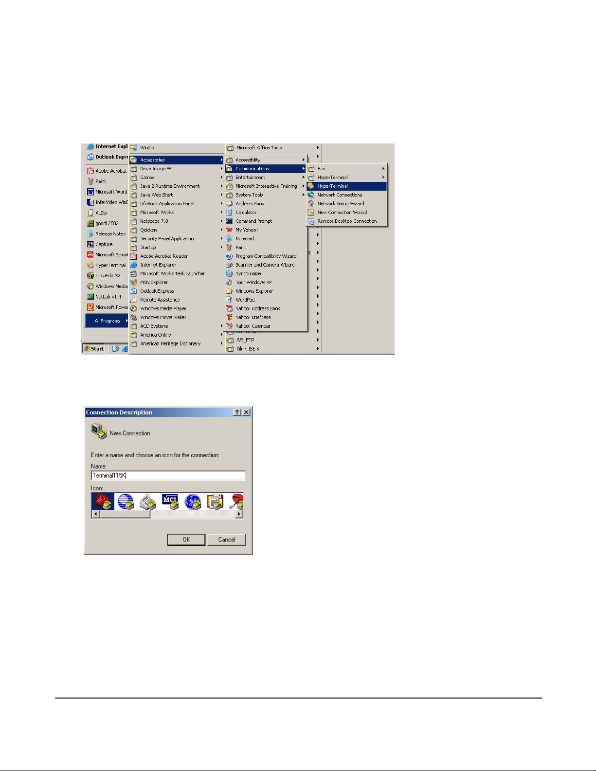
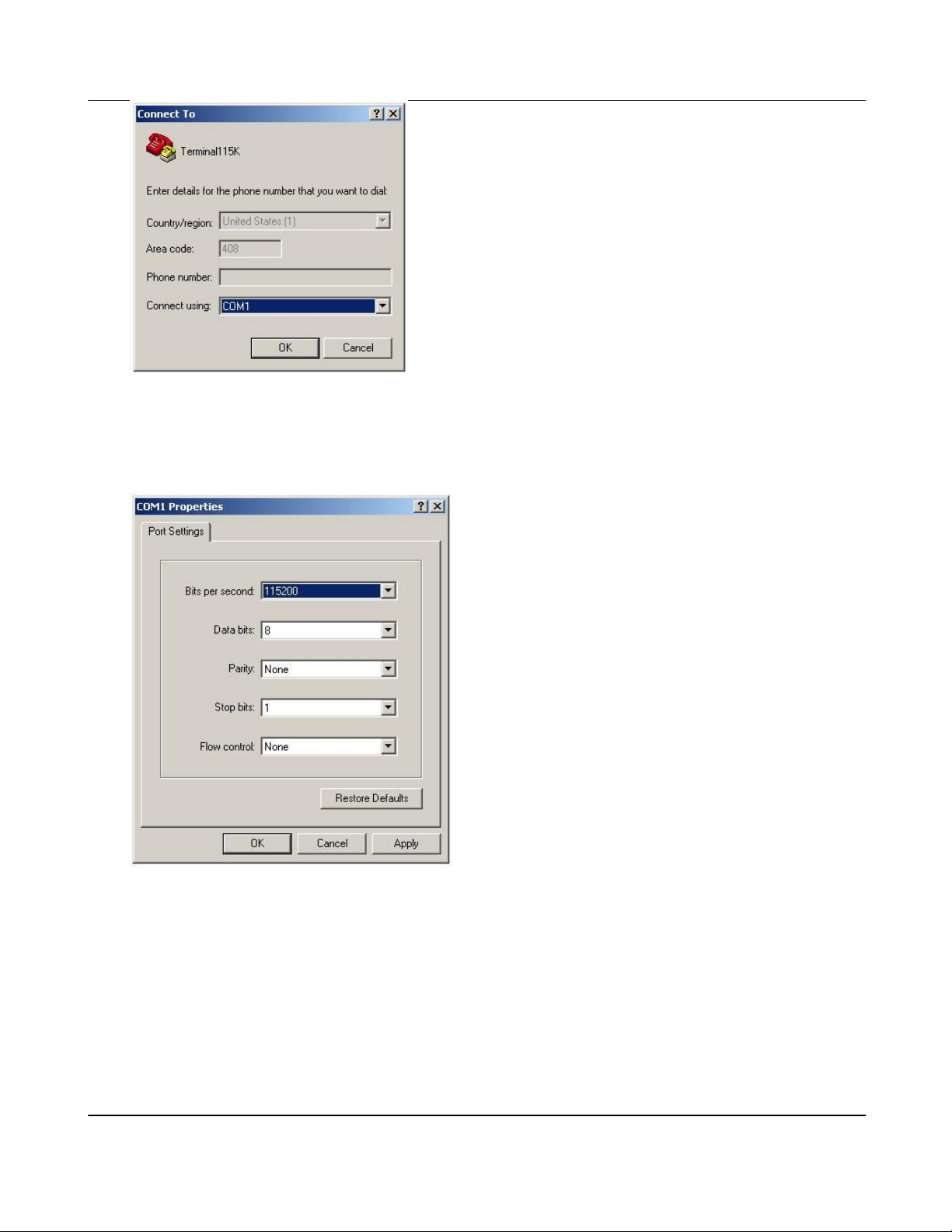
a. Select “Hyper Terminal”
b. Connection Description
c. Choose COM port.
Version 1.00 9/25/2007
Page 12
Techwell,Inc. TW8816 Evaluation Board User’s Manual
d. Set the COM port properties.
External Microcontroller: 115200bps, 8 bits data, No parity, 1 bit stop, No flow control
Internal Microcontroller: 9600bps, 8 bits data, No Parity, 1 bit stop, No flow control
Version 1.00 9/25/2007
Page 13
Techwell,Inc. TW8816 Evaluation Board User’s Manual
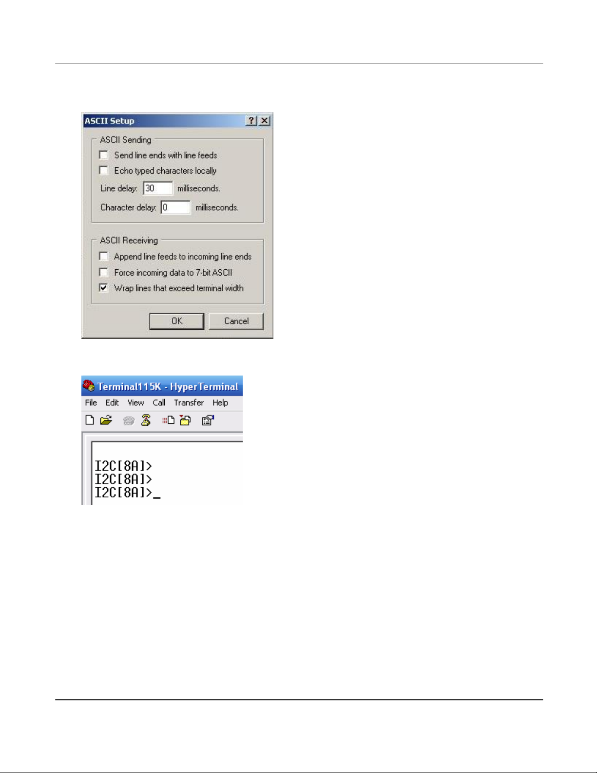
e. Set line delay :30~10ms, Character delay:0ms. Select [File\Properties\Settings\ASCII
Setup..\]. It is required when you download a new firmware or setting file.
f. Type [Enter] and see if it works.
g. Basic Commands set. These should be working in any firmware revision.
C Address Change address
D Index Dump registers
R Index Read register
W Index Data Write register
< , > Register++, Register—
/ Repeat previous command
Version 1.00 9/25/2007
Page 14

Techwell,Inc. TW8816 Evaluation Board User’s Manual
Examples
Change address:
[8A]>C 98
address : 98
[98]>
Dump registers:
[8A]>d 0
Read [Adrs:8Ah,00h] 0Ah
Read [Adrs:8Ah,01h] 83h
Read [Adrs:8Ah,02h] 68h
Read [Adrs:8Ah,03h] 20h
Read [Adrs:8Ah,04h] 00h
Read [Adrs:8Ah,05h] AFh
Read [Adrs:8Ah,06h] 40h
Read [Adrs:8A,07h] 02h
[8A>
Read register
[8A]>r 2
Read [Adrs:8Ah,02h] 68h
[8A]>
Write register
[8A]>w 2 60
Write 60h to [Adrs(8Ah)Index(02h)] Read [Adrs:8Ah,02h] 60h
[8A]>
Register++, Register— (by pressing ”>” and “<” button)
[8A]>r 10 // Read or write once.
Read [Adrs:8Ah,10h] 00h // [>] increase(++)
Write 01h to [Adrs(8Ah)Index(10h)] Read [Adrs:8Ah,10h] 01h // [>] increase(++)
Write 02h to [Adrs(8Ah)Index(10h)] Read [Adrs:8Ah,10h] 02h // [>] increase(++)
Write 03h to [Adrs(8Ah)Index(10h)] Read [Adrs:8Ah,10h] 03h // [>] increase(++)
Write 04h to [Adrs(8Ah)Index(10h)] Read [Adrs:8Ah,10h] 04h // [>] increase(++)
Write 05h to [Adrs(8Ah)Index(10h)] Read [Adrs:8Ah,10h] 05h // [<] Decrease(--)
Write 04h to [Adrs(8Ah)Index(10h)] Read [Adrs:8Ah,10h] 04h // [<] Decrease(--)
Write 03h to [Adrs(8Ah)Index(10h)] Read [Adrs:8Ah,10h] 03h
[8A]>
Repeat previous command (by pressing “/” button)
[8A]>r 2
Read [Adrs:8Ah,02h] 60h
[8A]> // [/]
Read [Adrs:8Ah,02h] 60h
[8A]>
Version 1.00 9/25/2007
Page 15
Techwell,Inc. TW8816 Evaluation Board User’s Manual
Special commands. Some of these commands are not available.
E E Level Set debugging message level
0: Only error message
3: Information message
* 2 Call loader
P On/Off flat panel
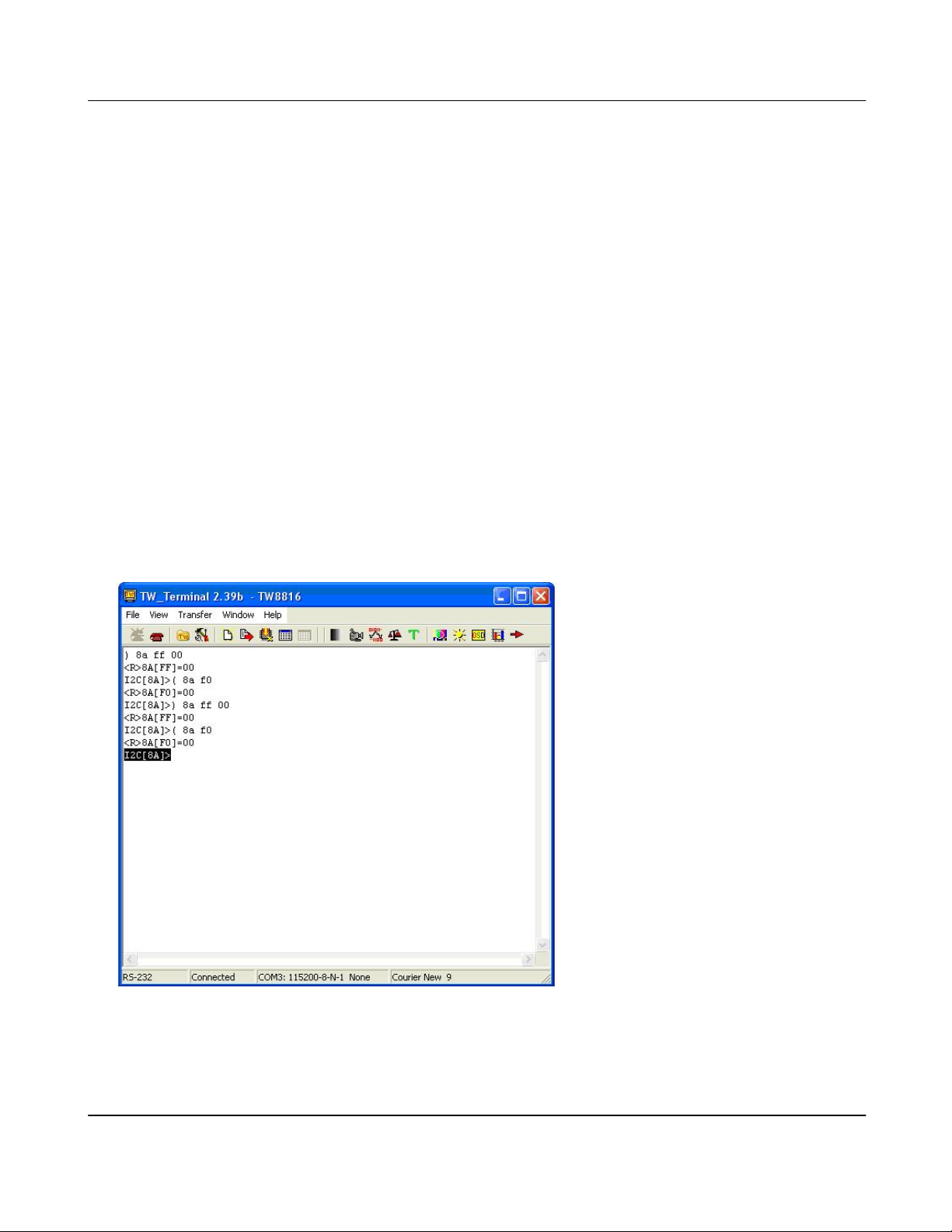
11. Using TW-Terminal2
TW_Terminal2.exe is a Microsoft Windows based program provided with the evaluation board for
testing, debugging, and updating firmware. Updating the firmware of the built-in microcontroller of
the TW8816 will require the use of the USB Interface Board and a special cable. Any other
features that require the I2C or SPI control will require the use of the USB Interface Board. The
TW_Terminal2 application has terminal emulation capabilities and has all the functionalities of the
HyperTerminal with the RS-232 connection. It also provides a friendly graphical user interface to
access and control the TW8816 registers. With this application, changing and monitoring
registers are made simpler and the user has better visibility. It allows faster firmware upgrade
without the need of an external eeprom programmer and a simple window interface for settings
such as gamma, decoder, ADC, scaler, and much more. Also, the flexible user interface can be
custom designed to the customer’s need by the use of TW_VEditor application.
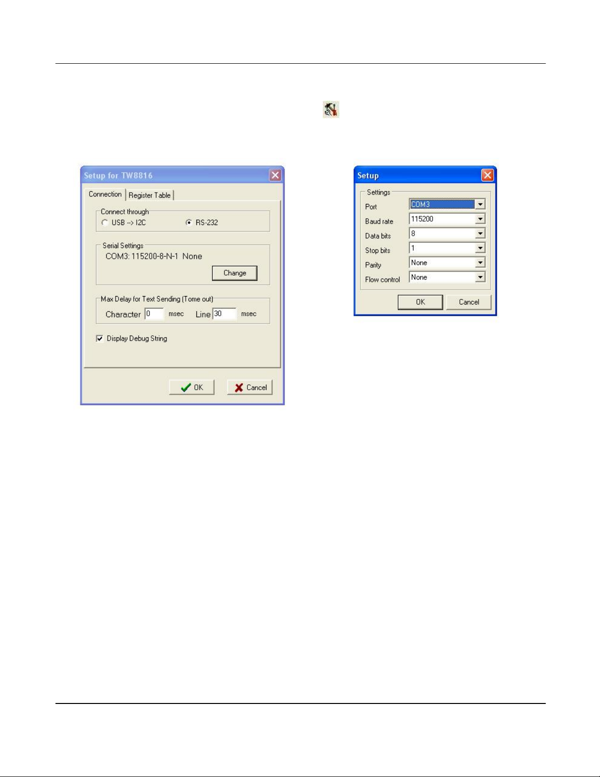
a. Connection Setup
The connection must be setup appropriately for each project.
Version 1.00 9/25/2007
Page 16
Techwell,Inc. TW8816 Evaluation Board User’s Manual
I. First, you must connect a USB Interface Board (RS-232 optional) to the
evaluation board, and also have the appropriate driver installed for the USB
Interface Board. Refer to USB interface Board User’s Manual.
II. Set up connection by clicking on
or going to Menu bar and selecting File >
Setup.
III. Then select the “Connection” tab and click on “Change” to get the “Setup”
window.
External Microcontroller: 115200bps, 8 bits data, No parity, 1 bit stop, No flow control
Internal Microcontroller: 9600bps, 8 bits data, No Parity, 1 bit stop, No flow control
IV. After the appropriate setting is completed, click on “OK” for “Setup” window and
then “OK” again for “Setup for TW8816” window.
b. Test the Connection
You may test the connection to the evaluation board by hitting “Enter” a couple of times. You
should observe the following being printed in the window:
I2C[8A]>
I2C[8A]>
I2C[8A]>
c. Basic Commands ( when using Main Window )
Basic Commands set. These should be working in any firmware revision.
C Address Change address
D Index Dump registers
Version 1.00 9/25/2007
Page 17

Techwell,Inc. TW8816 Evaluation Board User’s Manual
R Index Read register
W Index Data Write register
< , > Register++, Register—
/ Repeat previous command
Examples:
Change address:
[8A]>C 98
address : 98
[98]>
Dump registers:
[8A]>d 0
Read [Adrs:8Ah,00h] 0Ah
Read [Adrs:8Ah,01h] 83h
Read [Adrs:8Ah,02h] 68h
Read [Adrs:8Ah,03h] 20h
Read [Adrs:8Ah,04h] 00h
Read [Adrs:8Ah,05h] AFh
Read [Adrs:8Ah,06h] 40h
Read [Adrs:8A,07h] 02h
[8A>
Read register
[8A]>r 2
Read [Adrs:8Ah,02h] 68h
[8A]>
Write register
[8A]>w 2 60
Write 60h to [Adrs(8Ah)Index(02h)] Read [Adrs:8Ah,02h] 60h
[8A]>
Register++, Register— (by pressing ”>” and “<” button)
[8A]>r 10 // Read or write once.
Read [Adrs:8Ah,10h] 00h // [>] increase(++)
Write 01h to [Adrs(8Ah)Index(10h)] Read [Adrs:8Ah,10h] 01h // [>] increase(++)
Write 02h to [Adrs(8Ah)Index(10h)] Read [Adrs:8Ah,10h] 02h // [>] increase(++)
Write 03h to [Adrs(8Ah)Index(10h)] Read [Adrs:8Ah,10h] 03h // [>] increase(++)
Write 04h to [Adrs(8Ah)Index(10h)] Read [Adrs:8Ah,10h] 04h // [>] increase(++)
Write 05h to [Adrs(8Ah)Index(10h)] Read [Adrs:8Ah,10h] 05h // [<] Decrease(--)
Write 04h to [Adrs(8Ah)Index(10h)] Read [Adrs:8Ah,10h] 04h // [<] Decrease(--)
Write 03h to [Adrs(8Ah)Index(10h)] Read [Adrs:8Ah,10h] 03h
[8A]>
Version 1.00 9/25/2007
Page 18
Techwell,Inc. TW8816 Evaluation Board User’s Manual
Repeat previous command (by pressing “/” button)
[8A]>r 2
Read [Adrs:8Ah,02h] 60h
[8A]> // [/]
Read [Adrs:8Ah,02h] 60h
[8A]>
Special commands. Some of these commands are not available.
E E Level Set debugging message level
0: Only error message
3: Information message
* 2 Call loader
P On/Off flat panel
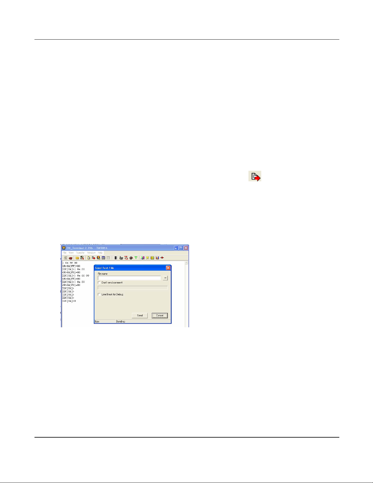
d. Using Text Files
Menu Bar and go to Transfer > Send Text files or click on the
text file downloading. This function is useful when multiple commands need to be executed. It
works same as typing every character in the text file. Also, this can be used with the files
created by the “Save Register” feature.
When text file is downloaded, the delay time between characters and between lines can be
adjusted by setting ‘Delay for Text Sending’. If the downloading is not working well, the delay
values need to be increased.
e. Firmware Up-grade
The USB Interface Board must be connected to the respective DB9 connector. For
Winbond firmware upgrade, it must be connected to CN13 of the TW8816 Main Board.
For internal microcontroller upgrade, we recommend to connect the USB Interface
Board to the “Embed MCU with TW9910 Board.”
i. Connect the SPI cable, which is a cable from the USB Interface Board (JP3 and
JP2) that is required to be connected to the SPI headers (J3) on the “Embed
MCU with TW9910 Board.” Also, make sure the firmware of the USB Interface
Board has supports SPI. Please refer to the USB Interface Board User’s
Manual for more instructions.
button. This will enable
Version 1.00 9/25/2007
Page 19
Techwell,Inc. TW8816 Evaluation Board User’s Manual
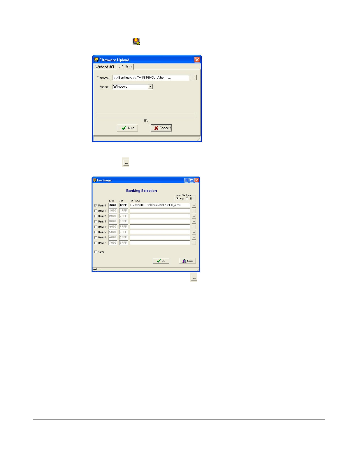
ii. Click on the Button and a “Firmware Upload” window will appear.
iii. Choose “SPI Flash” to update the firmware for the built-in microcontroller
iv. Click on
v. In “Hex Merge” window, click on
vi. Click on “Open” in the browser window, and then “OK” in the “Hex Merge”
window.
vii. Click on “Auto” and wait for completion.
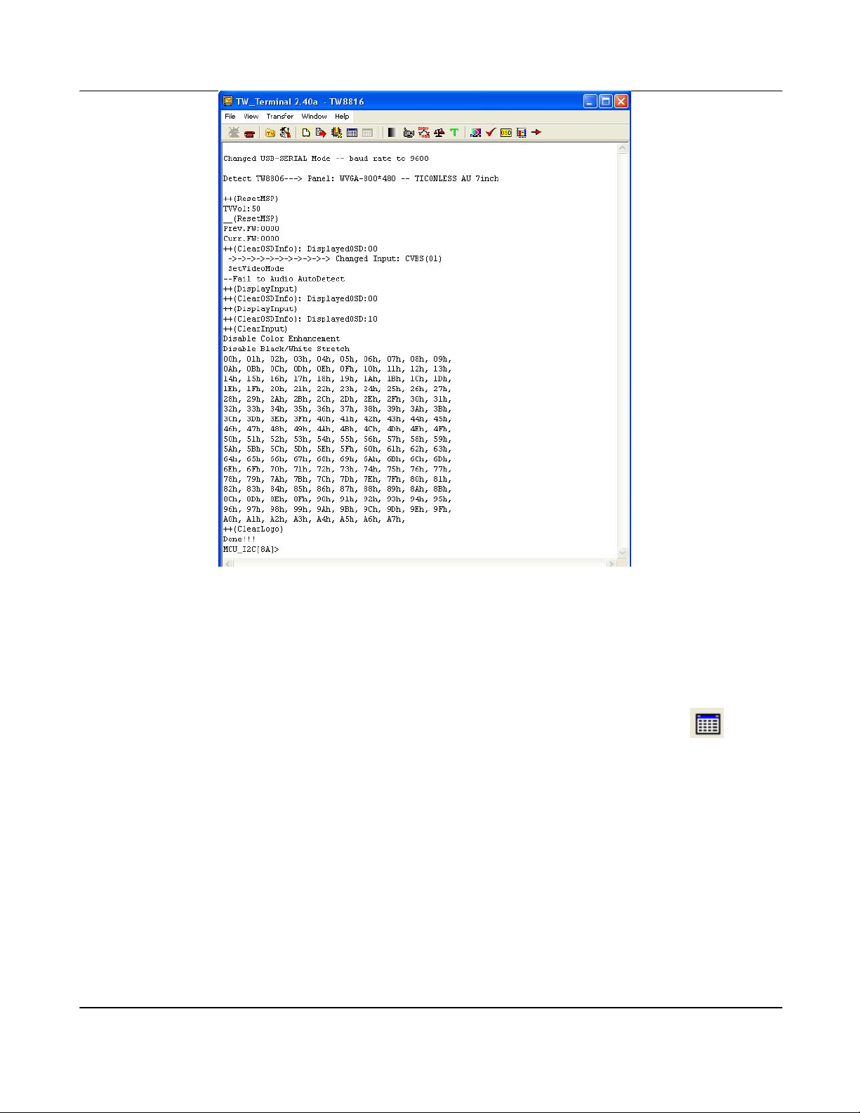
viii. After completion, the microcontroller will reboot and some boot up messages
similar to the following should appear in the respective TW_Terminal window.
Also, some LEDs should on the daughter board should be turned on by the
firmware.
after Filename to choose the selected firmware hex file.
to choose the firmware file desired.
Version 1.00 9/25/2007
Page 20
Techwell,Inc. TW8816 Evaluation Board User’s Manual
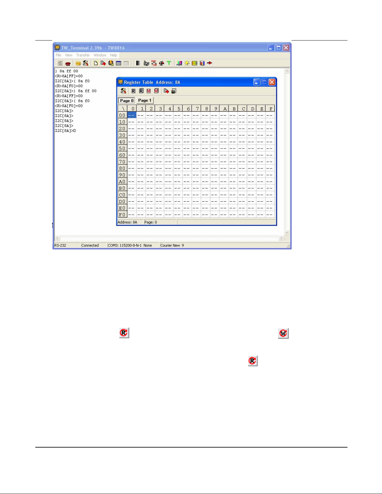
f. Register Control
This control reads out the page of register data based on the “Assigned Valid Register Table.”
The values are editable via this table format and the entire data page(s) can be read or written
individually or as a whole. Get the register table to read or write by clicking on
this page, the register data read may also be saved as a table text file or as a downloadable
text file. Table text files may be viewed easily, and downloadable text files may be used with
the “Send Text File…” function. Please refer to the TW_Terminal2 User’s Manual for more
detailed information.
. From
Version 1.00 9/25/2007
Page 21
Techwell,Inc. TW8816 Evaluation Board User’s Manual
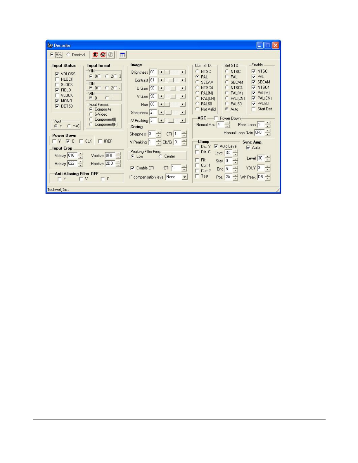
g. Other features of TW_Terminal
There are also other features that are made simple by Techwell’s sample application. You
may use the GUI to apply settings that you would normally have to manually apply by writing
directly to the registers. These GUIs are for Gamma, Decoder, ADC, TCON, SCALER,
CCFL, IMAGE ADJUSTMENT, OSD, SPI, SCALER, etc.
I. These Button
registers function, and both of them are displayed at the top of the window for each
feature.
II. When you open any of these windows, you may click on
III. When changing any of the setting, you will also be able to see the registers and data that
are being set in the main terminal.
IV. As an option, a customized “control” page may also be added. This customized
“control” page may be created using the TW_VEditor application. Please refer to
TW_Terminal2 User’s Manual for more detailed information on how to create control
pages that fits your application needs.
Example
provides read-all-registers function and button provides write-all-
to see the current settings.
Version 1.00 9/25/2007
Page 22
Techwell,Inc. TW8816 Evaluation Board User’s Manual
Version 1.00 9/25/2007
Figure 1 TW8806 Evaluation Board Input Output Connectors
Page 23

Techwell,Inc. TW8816 Evaluation Board User’s Manual
References:
USB Interface Board User’s Manual
TW_Terminal2 User’s Manual
TW8816 Datasheet
TW8816 Main Board Schematics
TW8816 Embed u-Controller with TW9910 Daughter Card Board Schematics
TW8806B A070VW01 Daughter Card Schematics
Version 1.00 9/25/2007
 Loading...