

Page 1
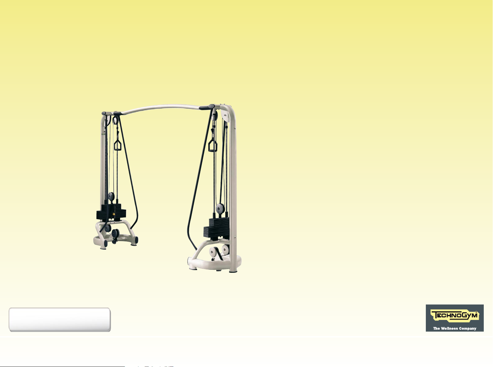
S E L E C T I O N
T H E S T R E N G T H E V O L U T I O N
Cables Crossed
User manual
All equipment
1
Page 2
Contents
Identification of the manufacturer and equipment ............................ 3
Description of the equipment ............................................................ 4
Technical data ................................................................................... 5
Safety devices and warnings ............................................................ 6
Assembling the number holder ......................................................... 8
Place of installation ........................................................................... 9
Lifting and moving the equipment ................................................... 10
Adjusting the equipment ................................................................. 12
Assembling the equipment .............................................................. 13
Securing the equipment .................................................................. 15
Removing the pulley mount ............................................................. 19
Routine maintenance ..................................................................... 20
Replacing the cable ......................................................................... 21
Replacing the spring hook .............................................................. 22
Technical Service ............................................................................. 23
Storage ............................................................................................ 24
Disposal ........................................................................................... 25
Using the equipment ....................................................................... 26
Cables Crossed
2
Page 3
Identification of the manufacturer and equipment
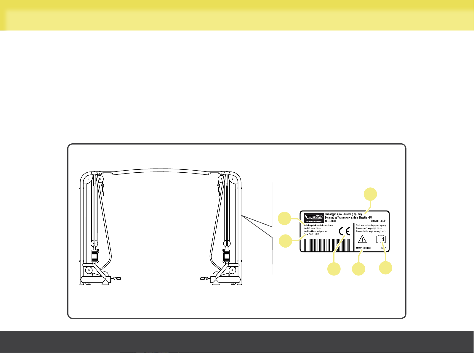
The equipment and manufacturer identification plate, placed behind frame bar, gives the following details:
A Manufacturer’s name and address
B CE Mark
C Serial number
D Maximum user weight
E Equipment classification
F Consultation of user manual required
Cables Crossed
D
E
B C
A
F
3
Page 4
Description of the equipment
C
A
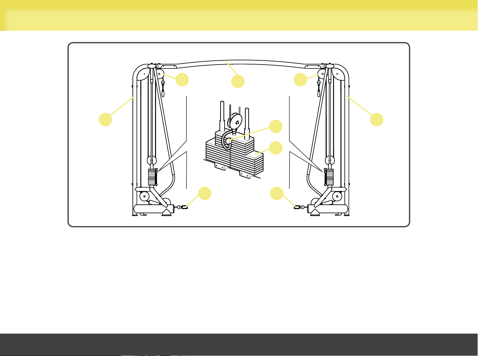
A Frame: load-bearing structure of the equipment.
D
F
C
A
E
B
D
B Weight stack: each pulley, i.e. high (C) or low (D), operated by the user, moves the weights along two guides by means of a cable.
A pin (E) is used for selecting the load, to adjust the exercise effort level.
F Beam: the component connecting the two frames.
Cables Crossed
4
Page 5
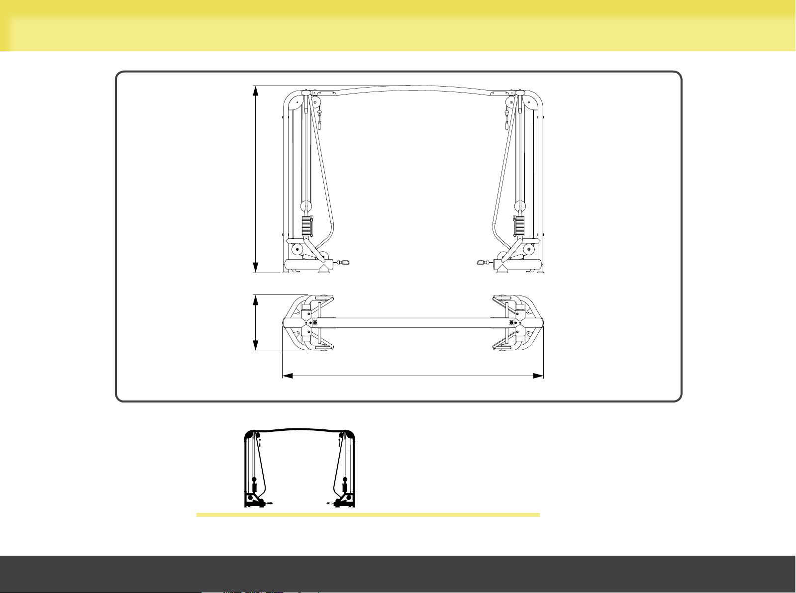
Technical data
(91")
2308 mm
Cables Crossed
(27")
686 mm
3213 mm
(127")
275 kg (606 lb)
5
Page 6
Safety devices and warnings
The maximum user weight is 180 kg (397 lb).
The equipment has no sharp corners.
All parts which come into contact with the user’s body are suitably protected with rubber coverings or padding.
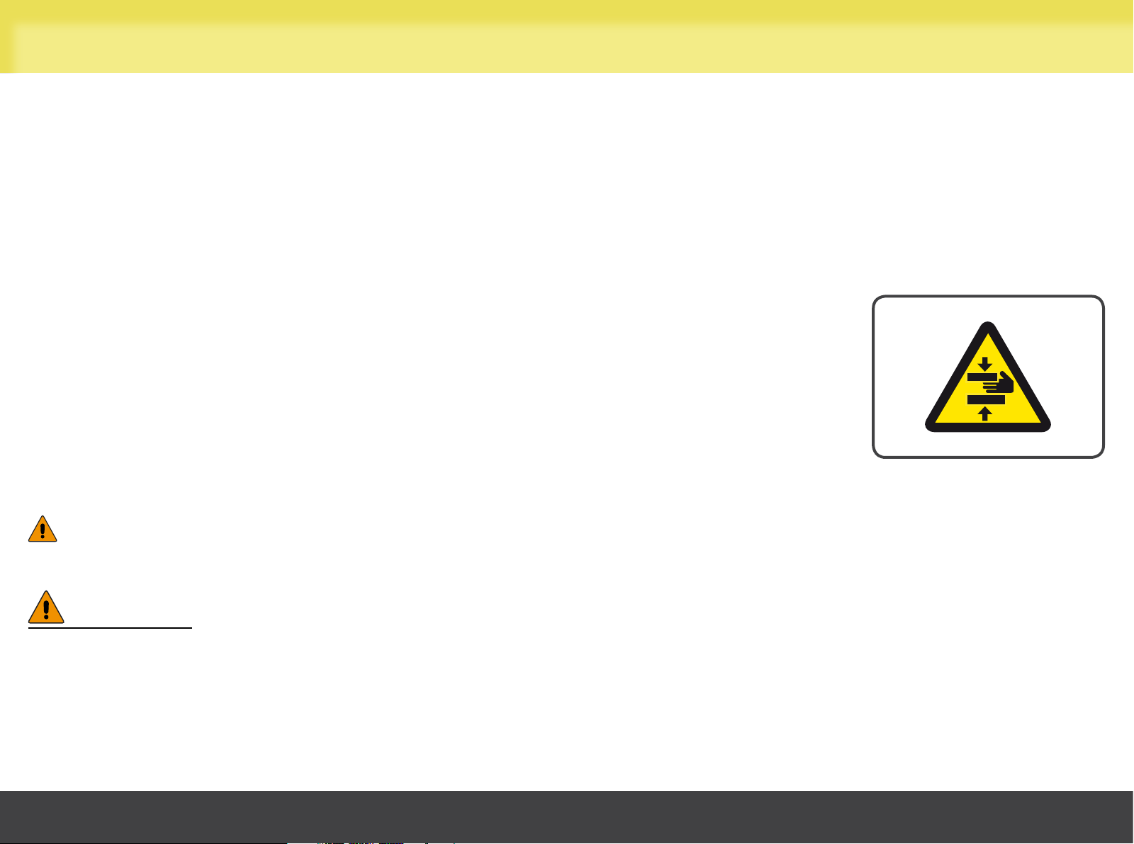
Pay particular attention to the parts of the equipment with labels indicating “BEWARE OF
CRUSHING”.
This symbol accompanies safety warnings and is used to draw attention to potential risks of personal injury. Pay attention
to all safety warnings accompanied by this symbol to avoid possible injury.
WARNING
During all operations involving transport, maintenance and cleaning, pay attention to any part of the equipment where
body parts may become trapped.
Cables Crossed
6
Page 7
Safety devices and warnings
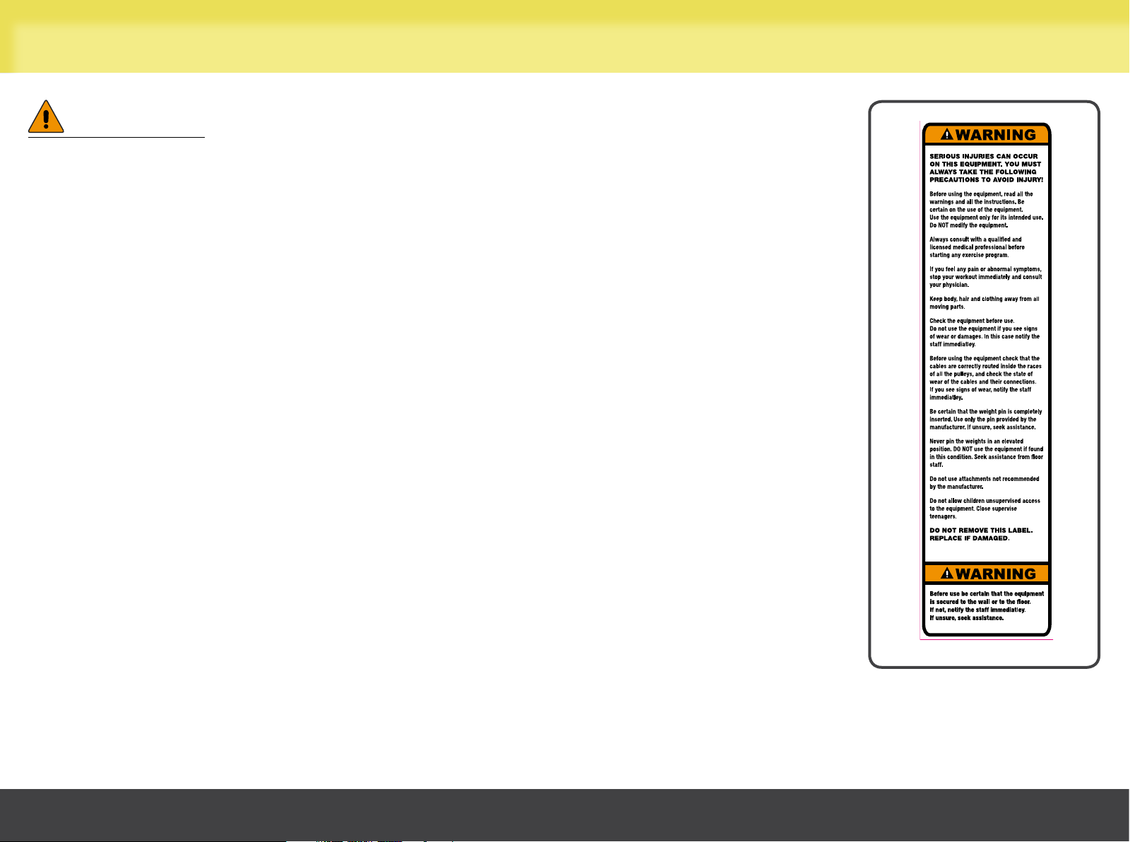
WARNINGS
Attention must be paid to the labels attached to the equipment, as they provide
information about possible risks and hazards.
We recommend immediately replacing the labels when they become damaged or difficult
to read.
Cables Crossed
7
Page 8
Assembling the number holder
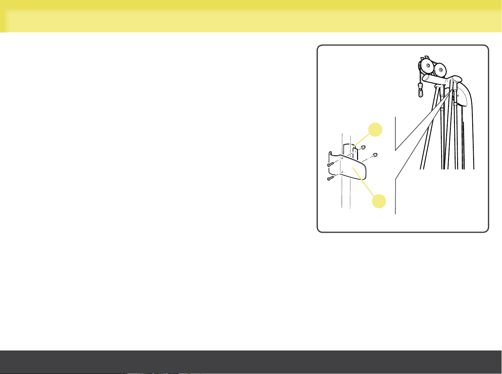
The number holder must be assembled immediately underneath the beams:
standing facing the equipment, affix the number holder on the left tube supporting
the guide, so that it is flush with the rubber stop of the guide.
The number holder is divided into two pieces: the larger section (A) goes on the
front, while the crescent closure (B) goes on the back of the equipment.
Insert the two screws (M5x6 Z) from the front of the equipment, mating them with
the two M5 cap nuts at the rear; then lock down using the appropriate spanners.
The number holder is optional.
B
A
Cables Crossed
8
Page 9
Place of installation
To ensure safe, comfortable and effective use of the equipment, the place of installation must comply with certain specific requirements;
in particular, before choosing where to install the equipment we recommend that you check that the following conditions are available:
- a temperature between +10°C and +25°C;
- sufficient ventilation to maintain a humidity level between 20% and 90%, when the equipment is in use;
- sufficient lighting to make the area a safe and relaxing place to exercise;
- sufficient clearance on all sides of the equipment, taking into account its maximum dimensions when in use, to ensure safety;
- a flat, stable and vibration-free floor surface, with sufficient load bearing capacity for the equipment’s weight.
If the equipment is to be installed in a public recreation area, the place of installation must comply with all the requirements of the
regulations currently in force.
WARNINGS
The equipment must be installed and used in a place where access and supervision are specifically controlled by the
owner.
When installing the equipment, use suitable personal protective equipment.
Cables Crossed
9
Page 10
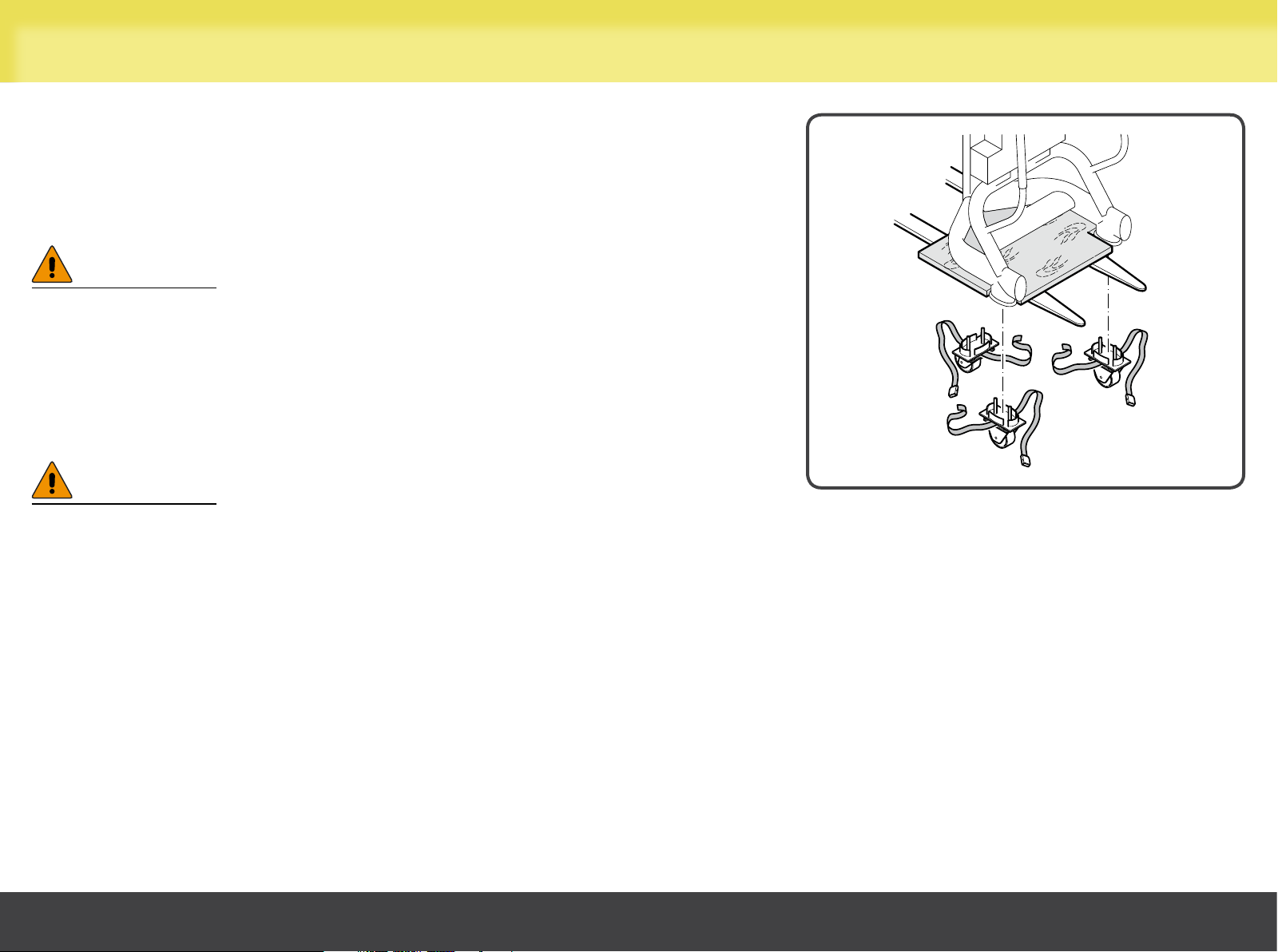
Lifting and moving the equipment
Before moving the equipment, firstly release it from the fastening and remove the
fastening beam (follow the instructions for assembling, in reverse order).
To move the equipment it is necessary to use three wheels: two fixed wheels and
one castor wheel.
WARNING
Move the equipment with great care to avoid it tipping over.
The wheels for moving the equipment snap on underneath the feet of the
equipment, after it has been lifted, and are held in place by the special straps.
Lift the equipment from the weight stack side using a transpallet or lift truck.
WARNING
Insert a rigid board between the equipment and the transpallet forks.
Cables Crossed
10
Page 11
Lifting and moving the equipment
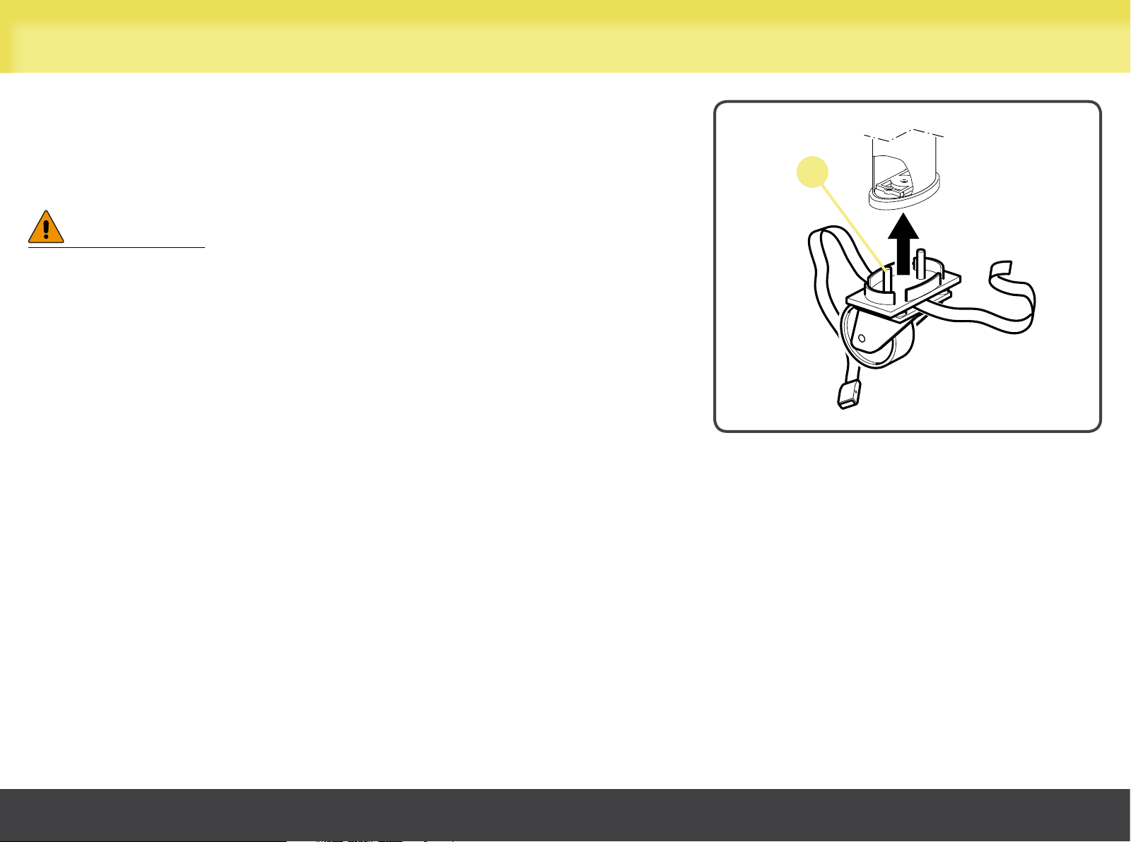
Fit the castor wheel beneath the weight stack base and the two fixed wheels
beneath the base from the opposite side: fit the pins (A) of the wheels into the
special holes under the equipment feet, then push all the way in.
Finally, place the wheels on the floor.
WARNINGS
When moving the equipment, push it only from the weight stack side,
and not from the other sides.
Do not use the equipment with the castors fitted. The castors are to
be used only for moving the equipment and must be removed before
exercising on it. After moving the equipment, it must be secured before
use.
A
Cables Crossed
11
Page 12
Adjusting the equipment
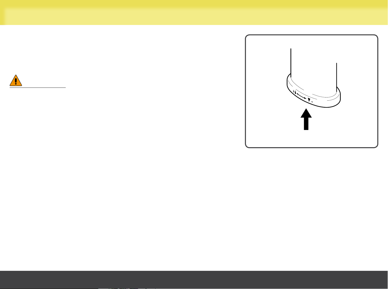
After the equipment has been positioned on the floor and secured to the wall,
check that it is level.
To do this, use the adjuster screw situated underneath the feet.
Lift the equipment and adjust the screw until the equipment is level.
WARNING
Given the weight of the equipment, we recommend that more than one
person be involved in lifting it.
Cables Crossed
12
Page 13
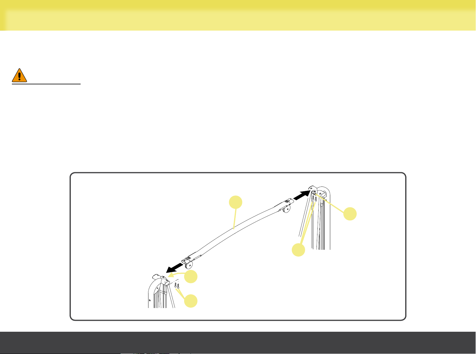
Assembling the equipment
Fit the wheels underneath the feet of each equipment unit.
Insert beam (A) into holes (B) of the frame of both equipment units to bring them together.
WARNING
Move each equipment unit with great care to avoid it tipping over.
Insert screws (C), two on each side.
Withdraw the wheels from the equipment feet.
Cables Crossed
A
B
C
B
C
13
Page 14
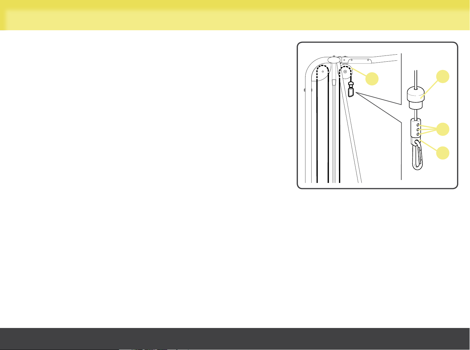
Assembling the equipment
Pass the cable through pulley (I); check the cable is correctly positioned in the
pulley groove.
Insert the rubber gaiter (L) and the attachment (N); then tighten the
screws (M).
Lower the rubber gaiter (L).
Securing the equipment to the ceiling or to the floor.
I
L
Adjust the equipment.
M
N
If the Cables Crossed are obtained from two Ercolinas, remove the pulley mount.
To couple together more Cables Crossed or one Cables Crossed with one or more Ercolina(s), please refer to the instructions for
"Joining the equipment units" as found in the Ercolina - Ercolina Rehab User manual.
Cables Crossed
14
Page 15
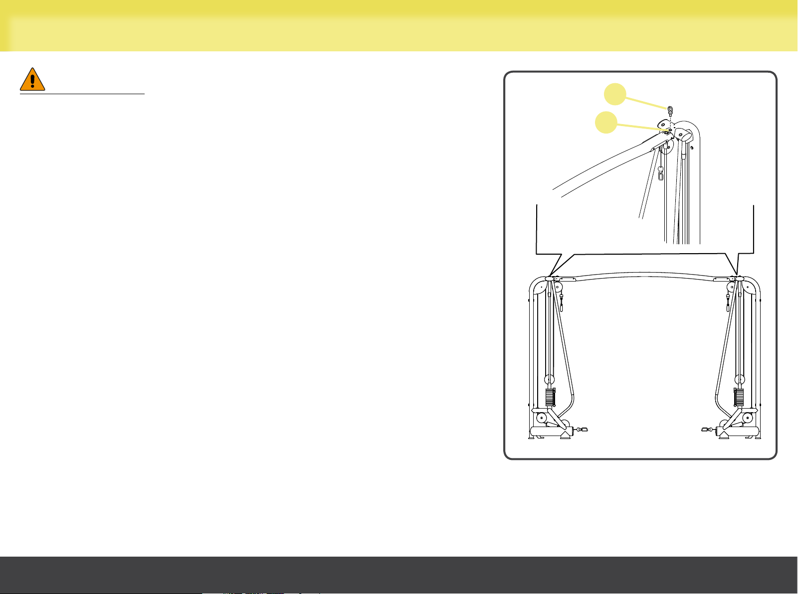
Securing the equipment
WARNINGS
It is obligatory to secure the equipment to the ceiling or to the floor
with the specific fixing screws and brackets. Technogym is not liable
for damage caused by failure to secure the equipment.
To secure the equipment, use anchor screws which strictly comply
with the following minimum requirement:
- minimum guaranteed load of 50 kg for securing the equipment to
the ceiling;
- minimum guaranteed load of 90 kg for securing the equipment to
the floor.
Securing the equipment to the ceiling
Use cables, ropes or chains to secure the Cables Crossed to the ceiling.
Tighten the eyebolts (D) into the threaded holes (E).
D
E
Cables Crossed
15
Page 16
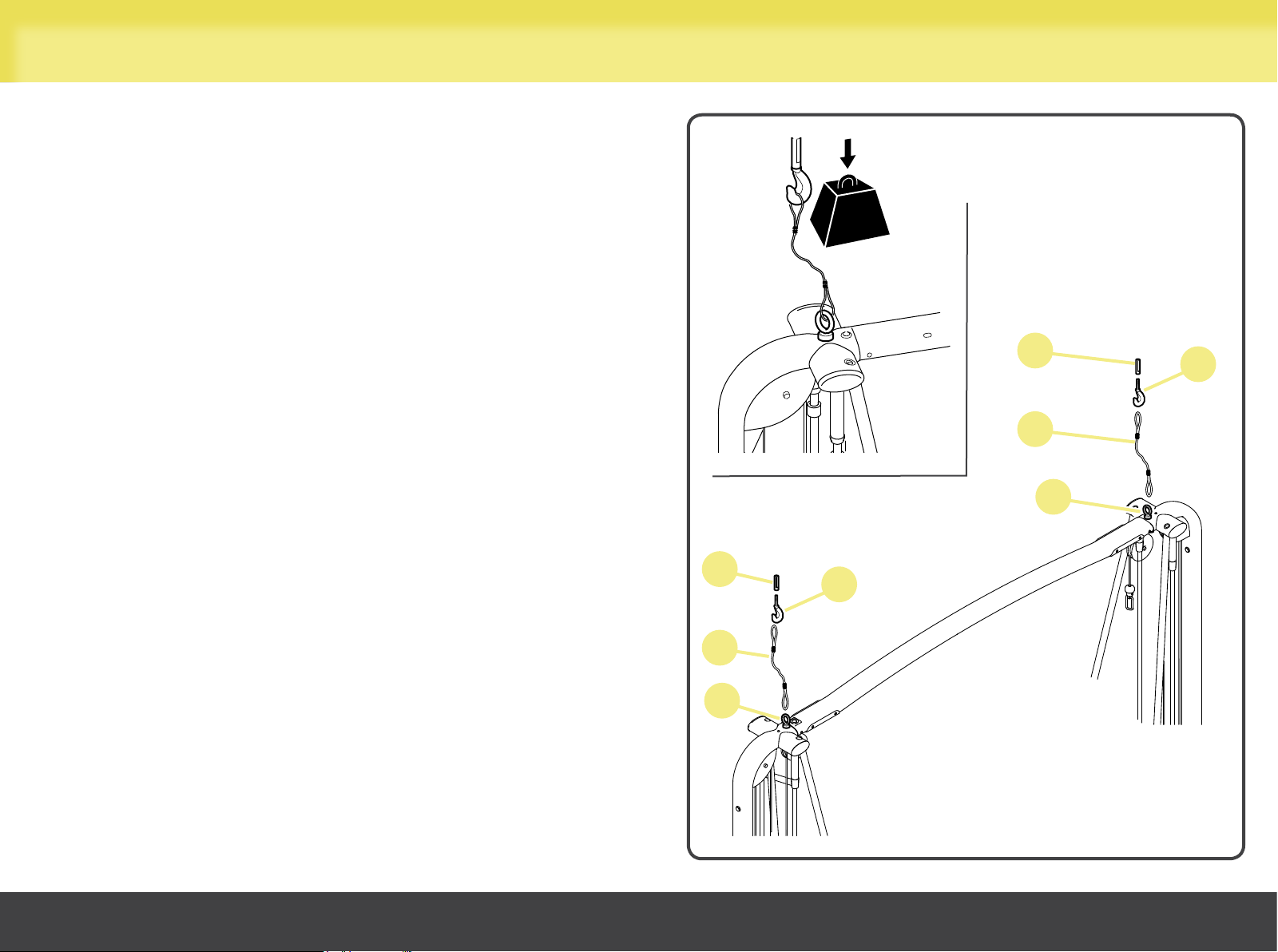
Securing the equipment
Drill two holes in the ceiling for hooks (F) and insert plugs (G) into
the holes.
Screw in hooks (F) into plugs (G) and tighten.
Connect hooks (F) to eyebolts (D) using cables, ropes or chains (H)
(not supplied with the equipment). The cables, ropes or chains
must be under slight tension.
min.
50 kg
G
F
H
D
G
F
H
Cables Crossed
D
16
Page 17
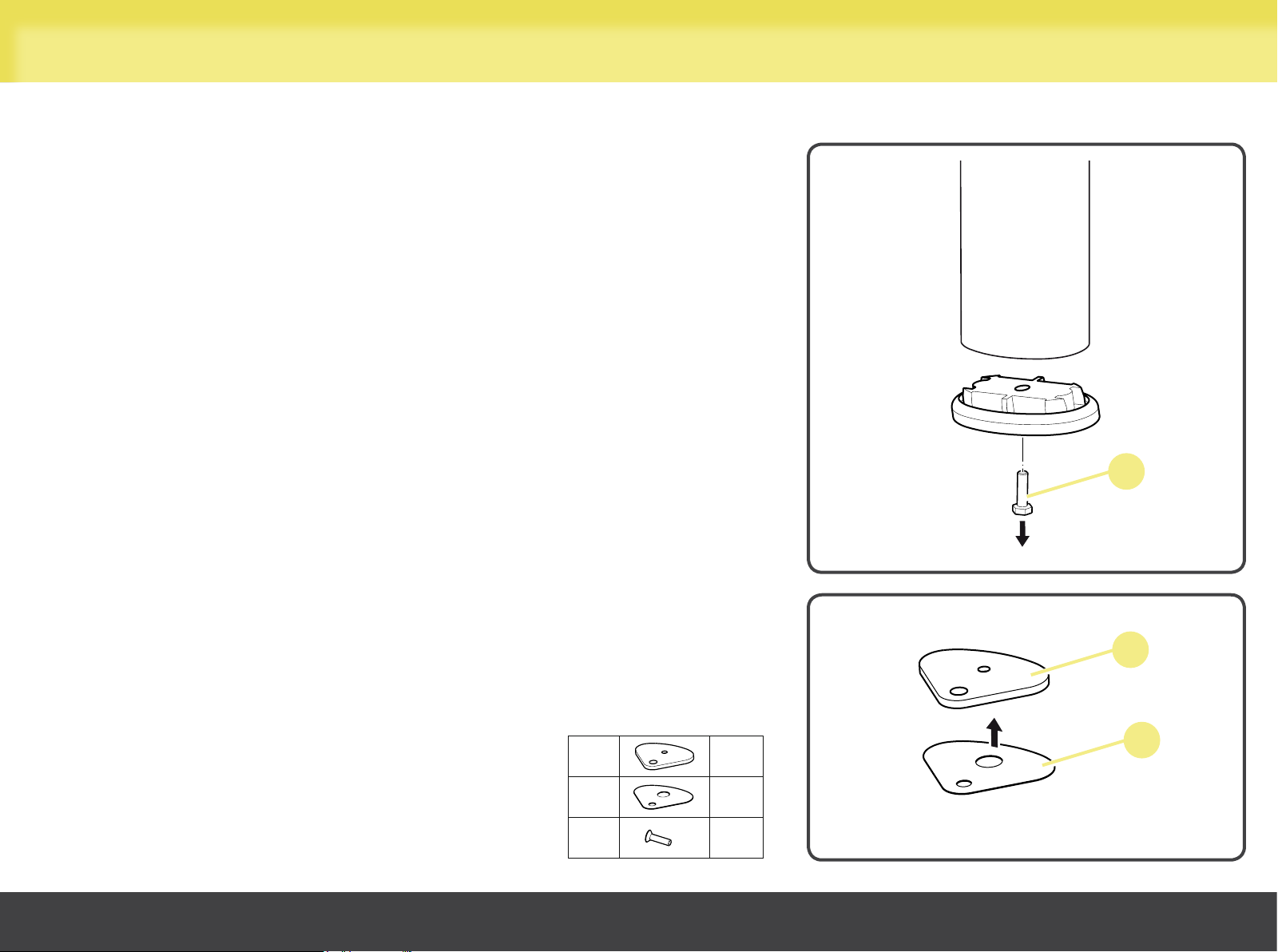
Securing the equipment
Securing the equipment to the floor
When anchoring the equipment to the floor, the feet need to be replaced: loosen
screw (A) to remove all the supporting feet.
Do not throw the original feet away, so that you can use them for inserting castors
when moving the equipment.
Apply adhesive protection (C) to the new feet (B).
A
Cables Crossed
B
C
D
B
6
6
6
C
17
Page 18
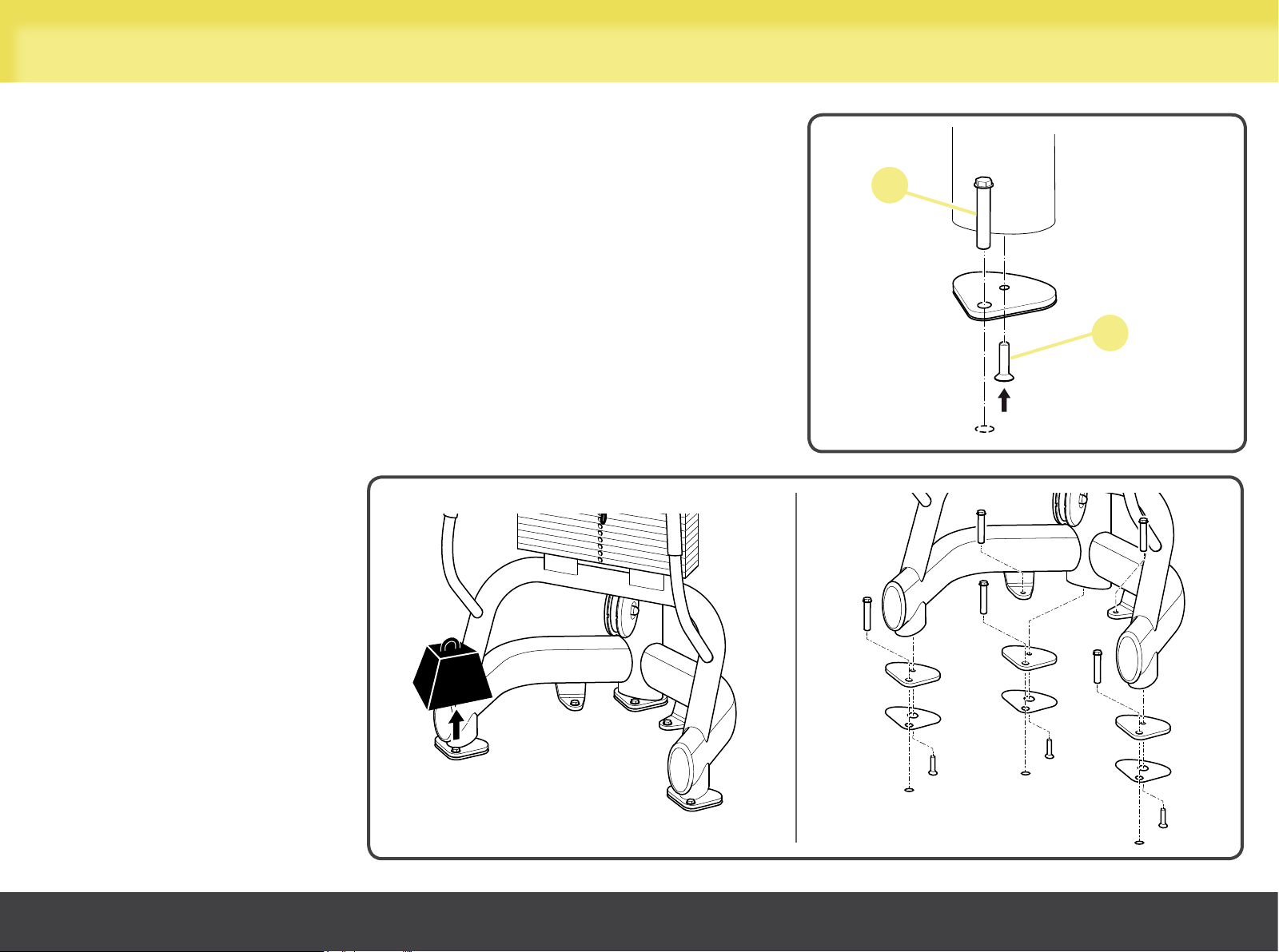
Securing the equipment
Attach all new feet to the equipment using the screws (D) provided.
Mark the position of the holes to be drilled in the floor:
- 3 holes for the new feet;
- 2 holes for the fasteners in the frame.
Drill the holes in the floor.
Insert anchor screws (E) and screw then tightly to the floor.
E
D
Cables Crossed
min.
90 kg
18
Page 19
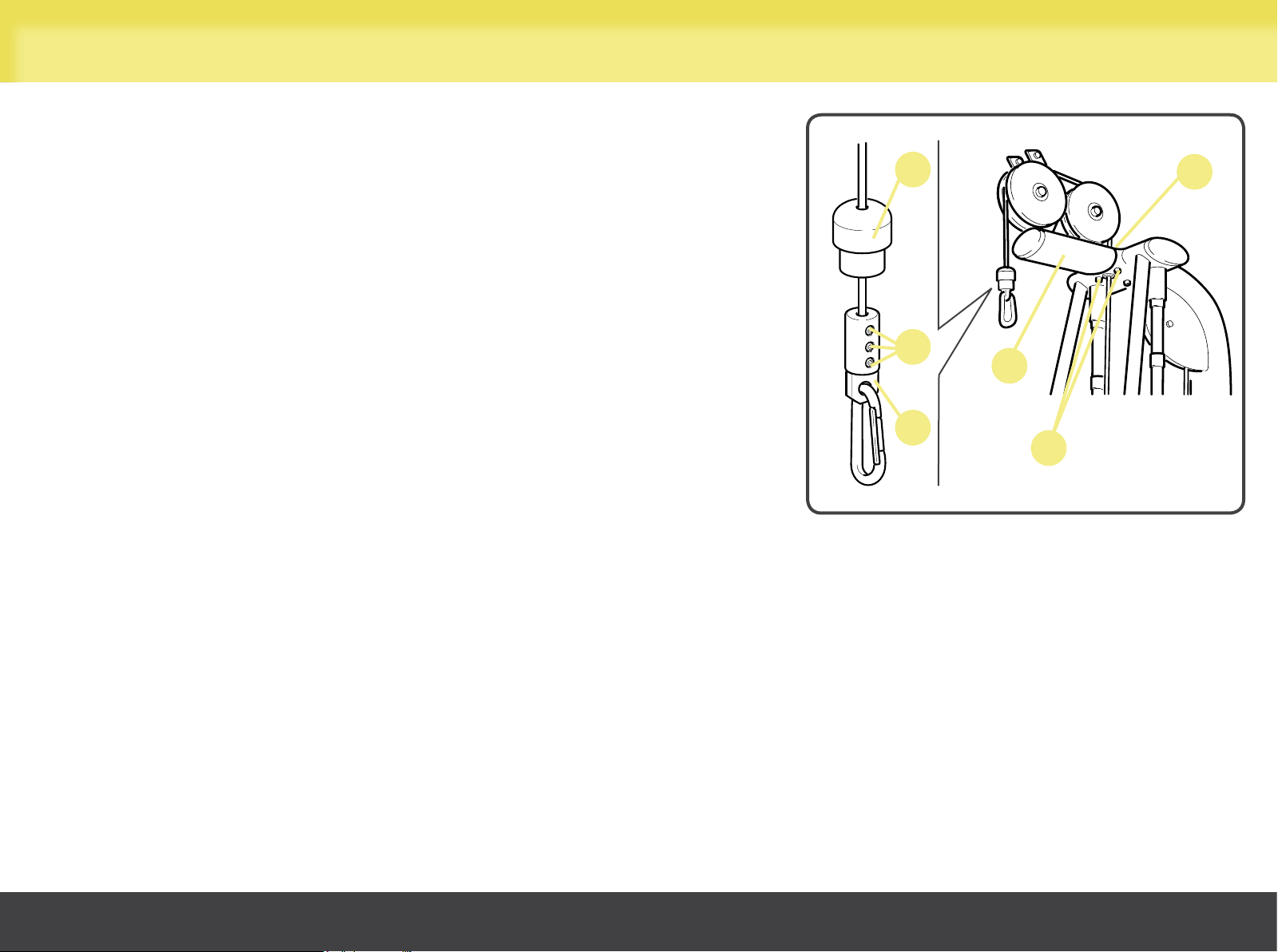
Removing the pulley mount
If the Cables Crossed are obtained from two Ercolinas, remove the pulley
mount (A):
- raise the rubber gaiter (B);
- unscrew the screws (C) and slide out the cable from the attachment (D);
- unscrew screw (E) and both screws (F);
- withdraw the pulley mount (A).
B
C
D
E
A
F
Cables Crossed
19
Page 20
Routine maintenance
WARNINGS
The safety of the equipment is assured only on the condition that it is carefully inspected every two weeks for any signs
of damage and/or wear and to ensure that it is perfectly secured to the wall.
Replace defective and worn components immediately, or alternatively remove the equipment from service.
The equipment should always be kept clean and free of dust, in compliance with good hygiene practice, especially if it is used in a
gym or by more than one person.
Use a moist cloth or a sponge and mild soap to clean the padded parts.
Wipe the outside of the equipment every week using a damp sponge.
Do not use chemicals or solvents.
WARNING
Be careful not to rub too hard on the drawings and instructions shown on the labels.
Oiling the weight stack guide rails:
- use a soft cloth to remove any dust and oil residues from the guide rails;
- slightly moisten the cloth with the oil supplied in the optional Basic Box kit;
- using this cloth, apply a very thin layer of lubricant over the guide rails, taking care not to apply too much.
Call the Technogym Technical Support Service for instructions on any maintenance operations not described in this manual.
Cables Crossed
20
Page 21
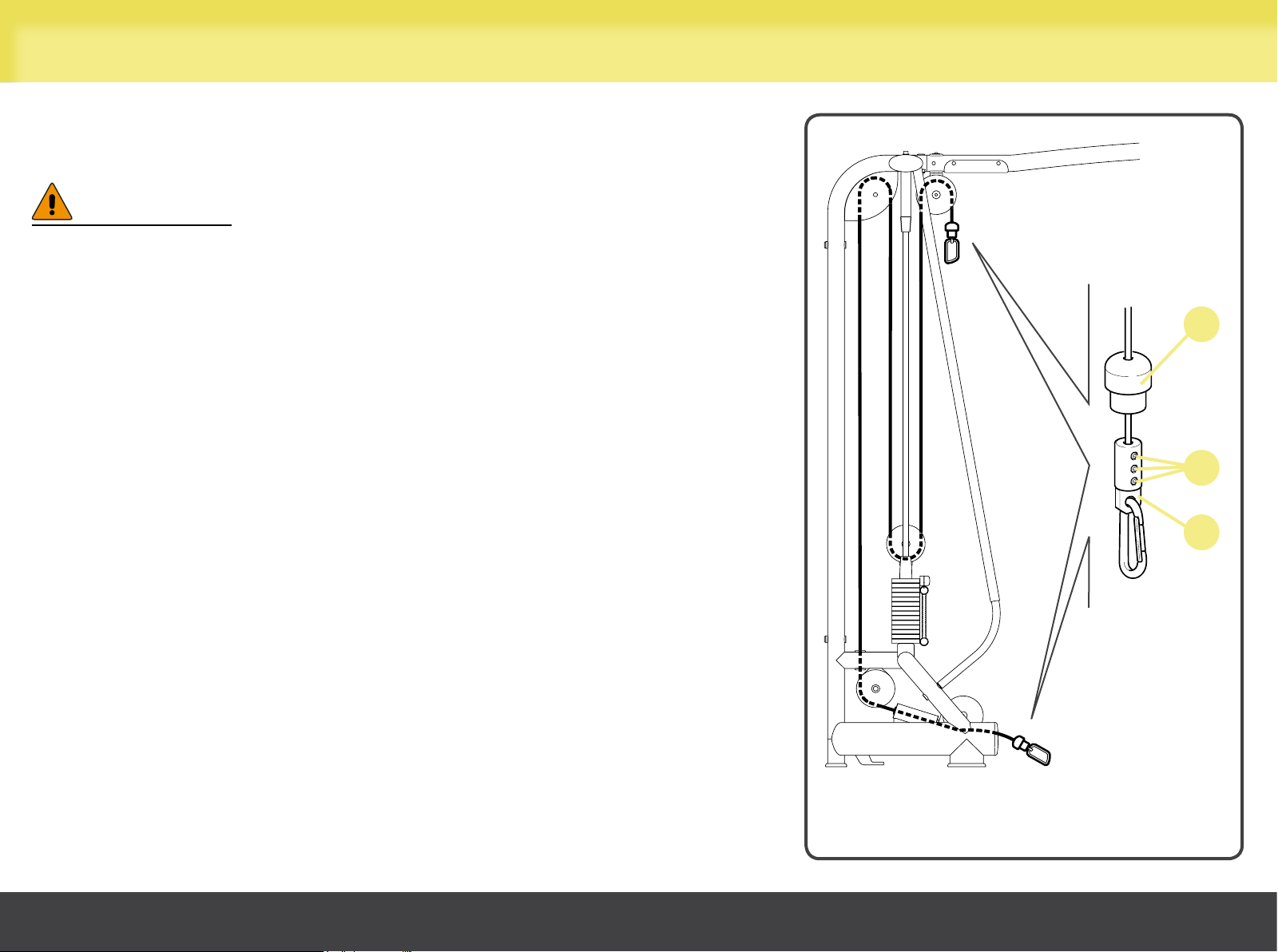
Replacing the cable
Cables must always be replaced at the first sign of wear, even if only the outer
rubber protection is worn.
WARNINGS
Carefully check the state of the cables once a month.
ALWAYS use cables supplied directly by Technogym.
The cable is joined to the high pulley and low pulley in the same way.
- remove any accessories;
- raise the rubber gaiter (A);
- unscrew the screws (B) and slide out the cable from the attachment (C);
- withdraw the entire cable from the equipment;
- insert the new cable (follow the original cable layout shown in the figure);
- insert the rubber gaiter (A) and the attachment (C); then tighten the screws (B);
- lower the rubber gaiter (A).
A
B
C
Cables Crossed
21
Page 22
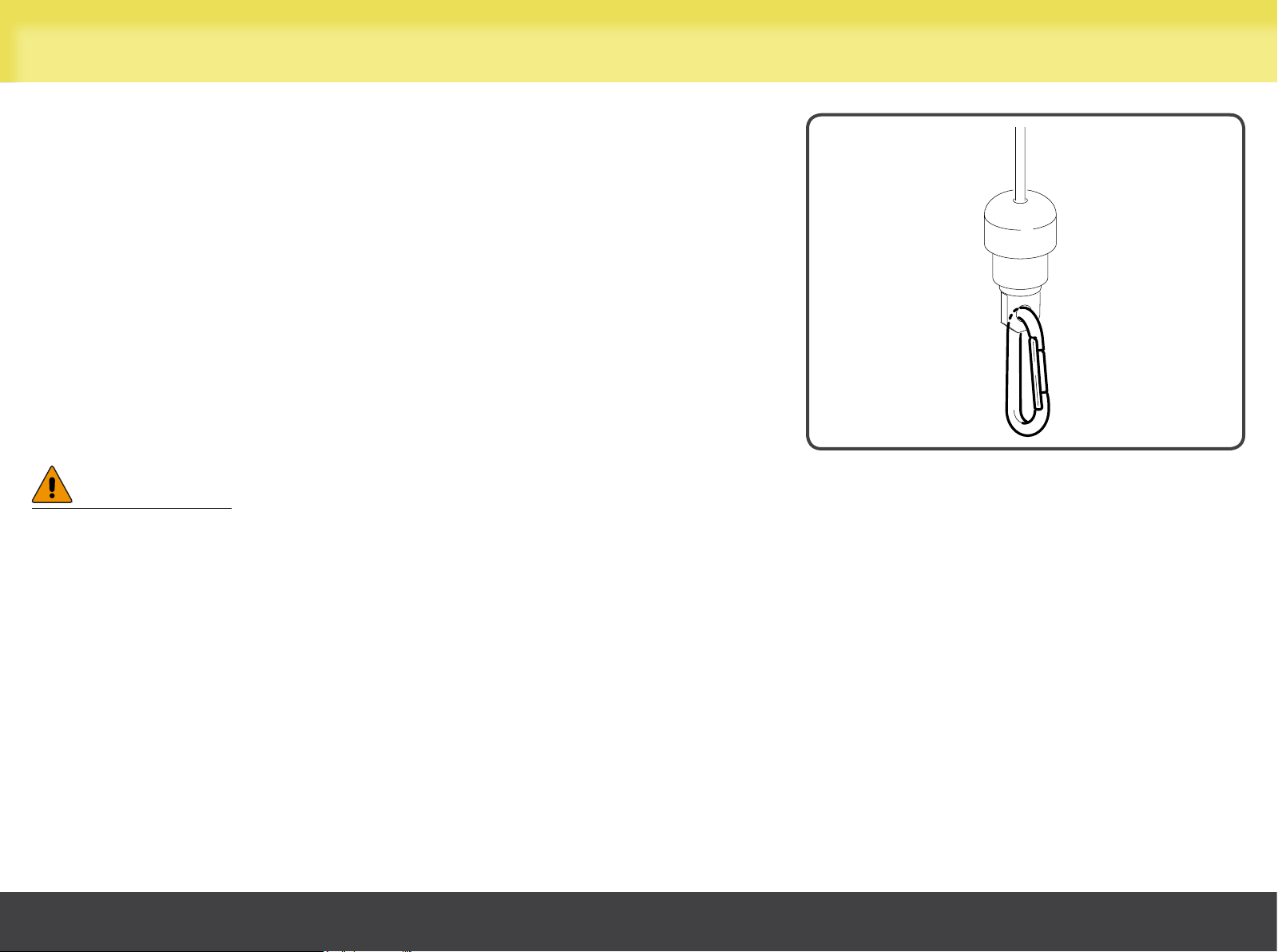
Replacing the spring hook
Always replace the spring hooks as soon as you notice the slightest signs of wear,
buckling, difficulty closing, or anything else that may interfere with its durability.
When replacing, always use a spring hook supplied directly by Technogym. If it
is impossible to obtain an original part, use a spring hook that strictly meets the
following minimum requirements:
- materials used: AISI 316 stainless steel;
- maximum capacity on main axis: 1600 kg (3500 lb);
- maximum capacity on minor axis: 350 kg (770 lb).
WARNINGS
Once a month, carefully check the condition of the spring hook.
Do not alter the spring hooks in any way.
Cables Crossed
22
Page 23
Technical Service
The Technogym Technical Support Service provides:
- telephone assistance;
- definition of service calls covered and not covered by warranty;
- on-site assistance;
- sending of original spare parts.
Technogym Technical
email: [email protected]
When contacting the Technogym Technical Support Service, please specify the following details:
- equipment model,
- date of purchase,
- serial number,
- precise description of the problem.
Support Service
tel: 0547 650650
fax: 0547 650150
WARNING
Any operations on the equipment carried out by persons not authorized by Technogym will invalidate the warranty.
Cables Crossed
23
Page 24
Storage
If the equipment is not expected to be used for a prolonged period, we recommend storing it:
- in a clean and dry place, covered with a cloth to protect it from dust;
- in an environment with a temperature between +10°C and +25°C and humidity between 20% and 90%.
Use the original packing materials, to better preserve the equipment.
Cables Crossed
24
Page 25
Disposal
It is always good practise to ensure that the equipment can never constitute a hazard; therefore do not leave the equipment where
children may play with it.
Do not dump the equipment in the environment, or in public areas or private areas accessible to the public.
The equipment is made from recyclable materials such as steel, aluminium and plastic, which must be disposed of in the manner
prescribed by the urban refuse collection regulations in force, by firms specialised in urban and environmental hygiene.
Cables Crossed
25
Page 26
Using the equipment
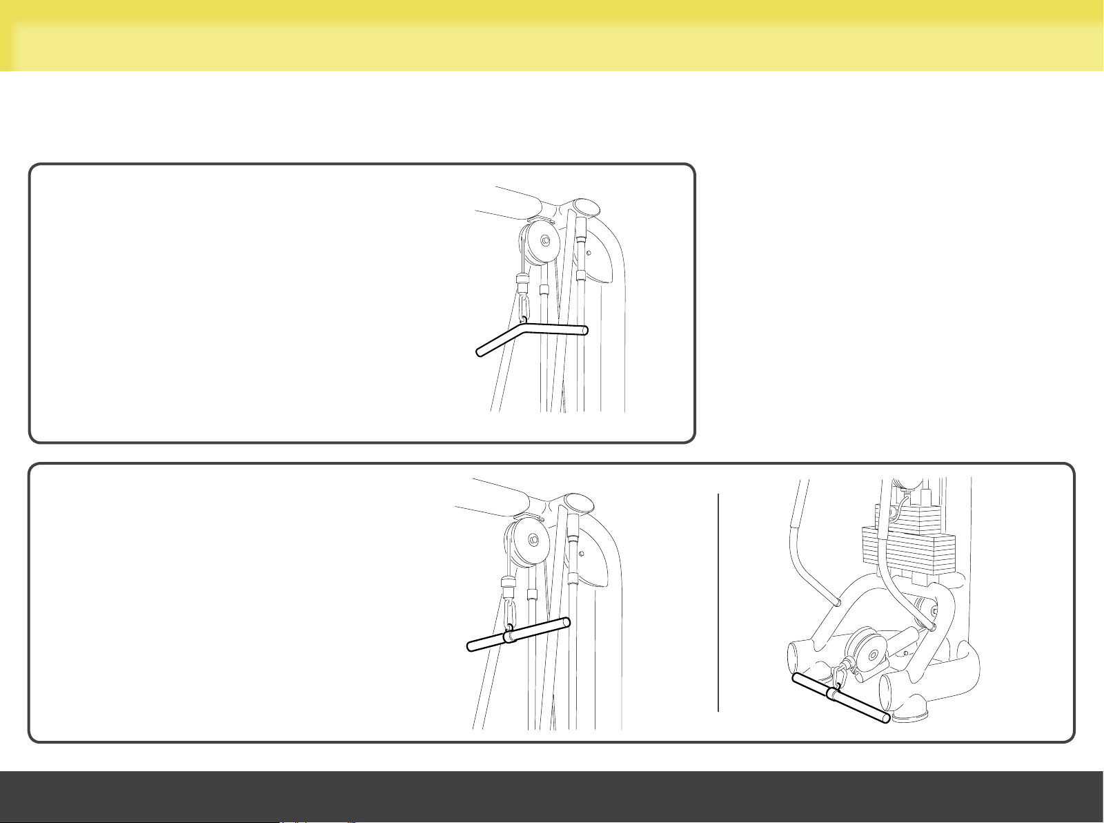
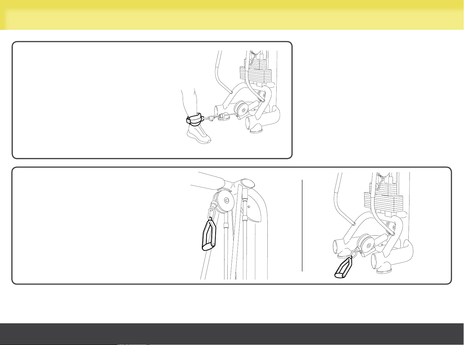
Some examples of installing accessories and a small selection of the exercises that may be carried out using the Cables Crossed
are described below.
Triceps bar
Jointed bar
Cables Crossed
26
Page 27
Using the equipment
Ankle strap
Handle
Cables Crossed
27
Page 28
Using the equipment
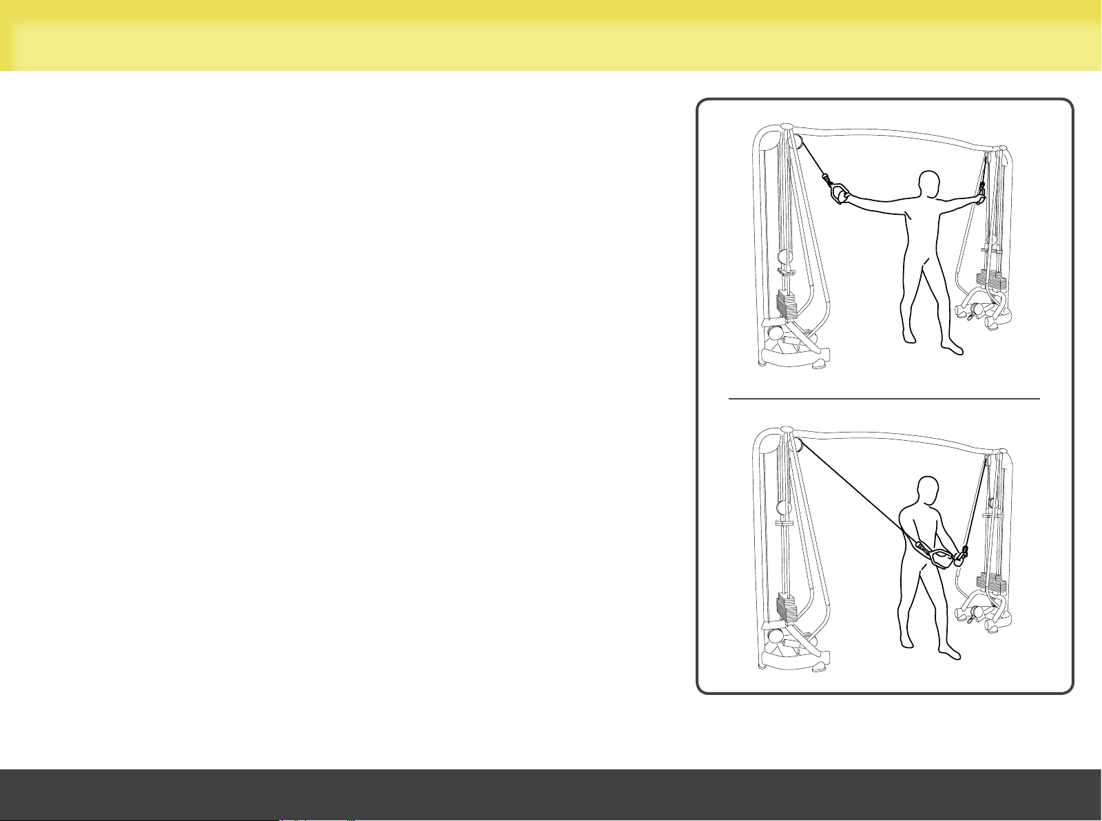
High pulley flyes (pectoral)
Handles on high pulleys.
Select the workload with the pin. Workload should be the same for both arms.
Move your legs slightly apart and move one in front of the other for greater stability.
Hold your arms outstretched at shoulder-height.
Move both outstretched arms downward at the same time and bring your hands
together in front of your torso.
Maintain a smooth controlled speed; we recommend a slower speed during the
return phase than during the approach phase.
The weight stack should not return completely to rest position during the return
phase.
Cables Crossed
28
Page 29
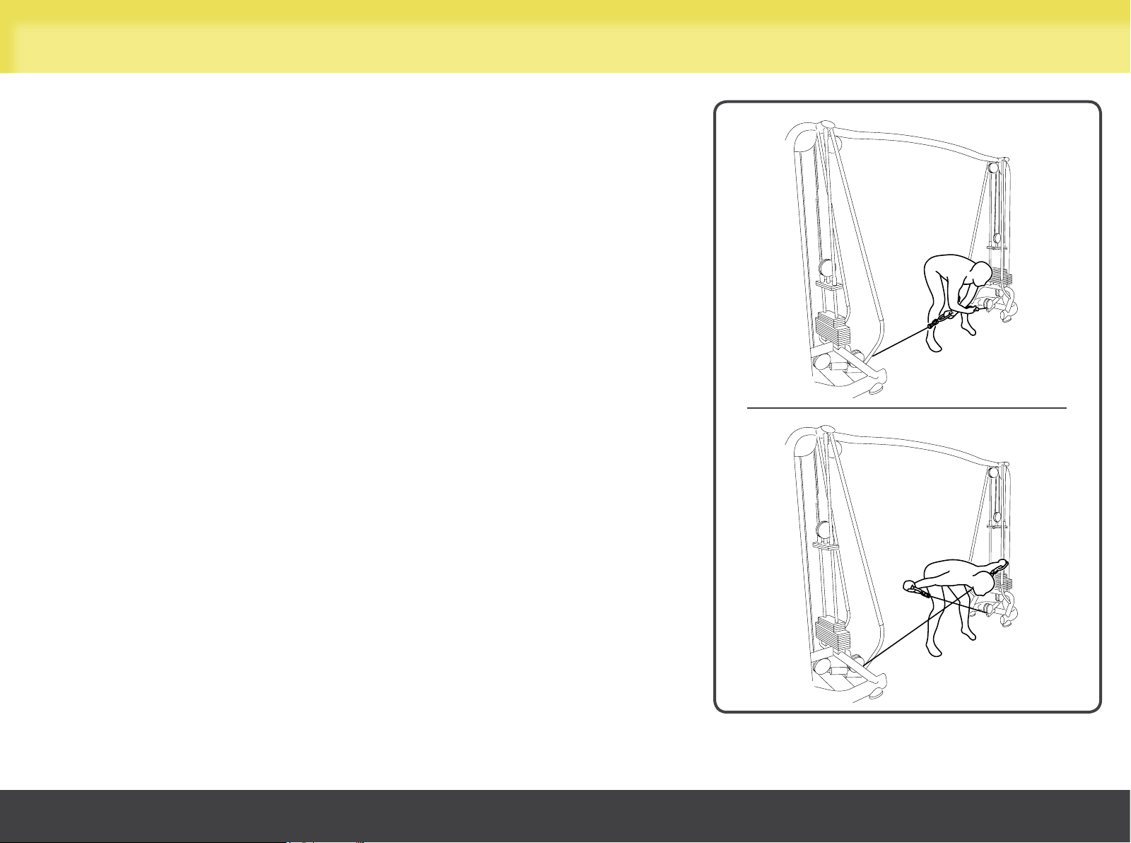
Using the equipment
Lateral raises 90° trunk (posterior deltoid)
Handles on low pulleys.
Select the workload with the pin. Workload should be the same for both arms.
Stand with your legs slightly apart and bend your torso to 90°; your arms should
be crossed and slightly bent under your torso.
Raise both arms simultaneously until they are parallel with the ground and
outstretched, without making contralateral movements with your torso.
Maintain a smooth controlled speed; we recommend a slower speed during the
return phase than during the approach phase.
The weight stack should not return completely to rest position during the return
phase.
Cables Crossed
29
Page 30
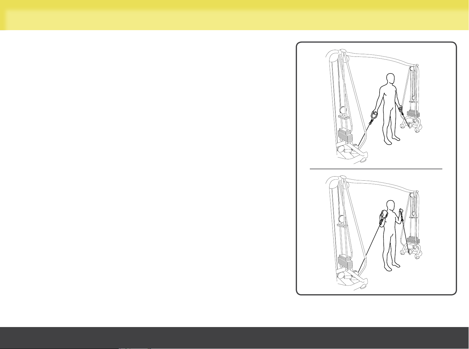
Using the equipment
Forearm curls (biceps)
Handles on low pulleys.
Select the workload with the pin. Workload should be the same for both arms.
Stand with your legs slightly apart for greater stability and grasp the handles with
outstretched arms, reverse grip.
Curl both forearms up at the same time without moving your upper arms.
Maintain a smooth controlled speed; we recommend a slower speed during the
return phase than during the approach phase.
The weight stack should not return completely to rest position during the return
phase.
Cables Crossed
30
Page 31
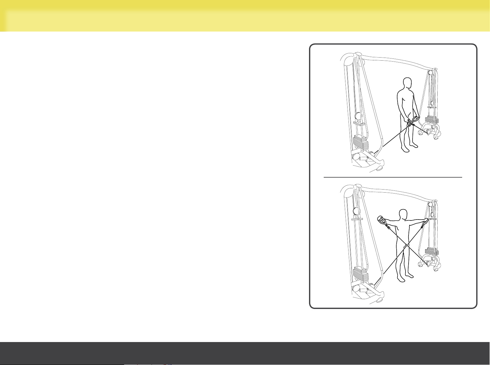
Using the equipment
Lateral raises (lateral deltoids)
Handles on low pulleys.
Select the workload with the pin. Workload should be the same for both arms.
Stand with your legs slightly apart for greater stability and your arms stretched
downward.
Cross the cables.
Raise both arms simultaneously until they are parallel with the ground, without
making contralateral movements with your torso.
Maintain a smooth controlled speed; we recommend a slower speed during the
return phase than during the approach phase.
The weight stack should not return completely to rest position during the return
phase.
Cables Crossed
31
 Loading...