

Page 1
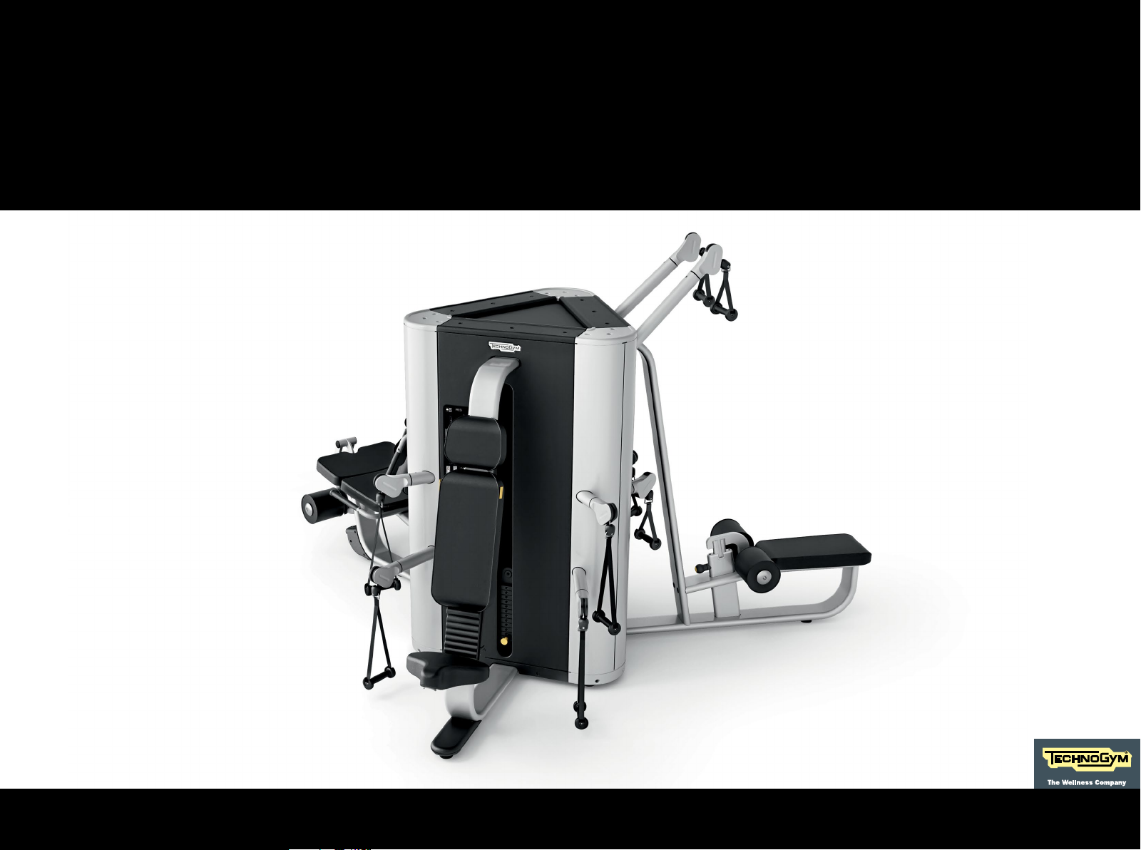
TOWER
- Core & Leg Extension/Curl
- Press & Overhead Press
- High & Low Pull
PLURIMA
THE SMART MULTISTATION
User manual
Page 2
Contents
Important safety instructions ....................................................................... 3
Personal safety ...............................................................................................5
Identication of the manufacturer and equipment .................................... 8
Using the equipment ...................................................................................... 9
Core & Leg Extension/Curl ......................................................................11
Press & Overhead Press ..........................................................................16
High & Low Pull ......................................................................................... 21
Technical data ................................................................................................26
Place of installation ......................................................................................27
Lifting and moving the equipment .............................................................29
Routine maintenance ...................................................................................30
Replacing the padded parts ......................................................................... 31
Core & Leg Extension/Curl ......................................................................32
Reaching the inside parts ............................................................................42
Replacing the cable .......................................................................................46
Core & Leg Extension/Curl ......................................................................47
Press & Overhead Press .......................................................................... 59
High & Low Pull .........................................................................................68
Adjusting cable tension ................................................................................77
Technical Support Service ............................................................................ 78
Storage ...........................................................................................................79
Disposal .........................................................................................................79
Press & Overhead Press ..........................................................................36
High & Low Pull ......................................................................................... 39
Replacing handles and straps .....................................................................40
Core & Leg Extension/Curl ......................................................................40
Press & Overhead Press ..........................................................................41
High & Low Pull .........................................................................................41
2PLURIMA
Page 3
Important safety instructions
You should always consult with a qualied and licensed medical professional or healthcare practitioner before starting any nutritional, diet,
stretching or exercise program. You are advised to investigate and inform yourself about any health related actions and choices you make.
Read all instructions before using the equipment. These instructions were written to ensure your safety and to protect the equipment.
Equipment in the Plurima range is intended for commercial use.
W
To reduce the risk of injury, take the following precautions.
The products in the Plurima range are units of xed weight training equipment units that can be used for body-building or sculpting, physical
activity aimed at keeping in shape, physical education and training for specic competitions and sports.
The equipment must be used by only one user at a time.
Use any equipment only for its intended use as described in the user manual. Only perform the exercises for which the equipment has been
designed, following the instructions given in the manual. Any other use is to be considered improper and therefore dangerous.
Do not use attachments not recommended by the manufacturer.
The equipment must be installed and used in a place in which access and supervision are specically controlled by the owner.
Do not allow unsupervised children close to the equipment.
3PLURIMA
Page 4
Important safety instructions
Close supervision is necessary when any equipment is used by, on or near children, invalids or disabled persons.
Never operate any equipment if it has damaged power supply cord, if it is not working properly or if it has been dropped or damaged. In these
circumstances, contact the Technogym Technical Support service.
Keep hands away from moving parts.
Never drop or insert any object into any opening.
Do not use outdoors. Do not leave the equipment outdoors, exposed to the elements (rain, sun, wind, etc.). Do not expose the equipment to
water jets.
The maximum user weight is 180 kg (397 lb).
4PLURIMA
Page 5
Personal safety
Assemble the equipment completely prior to use.
Keep the equipment in good working conditions.
Prior to each use, check the equipment and make sure the cable is positioned correctly in the grooves of all the pulleys and check cable wear.
If you see signs of wear, contact Technogym's Technical Support service.
Do not continue using the equipment if it is not working properly.
Do not attempt any maintenance work on the equipment other than what is described in the user manual.
Assemble and use the equipment only on a solid and at surface.
Do not place anything on the frame.
Use of the equipment is subject to a medical examination in relation to the intended type of workout, and compliance with the conditions for
use laid down by the manufacturer.
Persons suering from certain physical conditions may only use the equipment under the strict supervision of a specialist doctor.
Before starting any workout, make sure your position on the unit is correct, and be careful with any components that might constitute an
obstruction.
Wear proper workout clothing and shoes during training; do not wear garments that block perspiration; do not wear loose clothing. Tie long hair
back. Keep garments or towels away from moving parts.
Choose exercises suited to your physical characteristics and state of health, starting with light work loads.
Do not overexert yourself or work to exhaustion. If you feel pain or have strange symptoms stop your workout immediately and seek medical
advice.
5PLURIMA
Page 6
Personal safety
Make sure that the weight pin is completely inserted. Use only the pin provided by the manufacturer. Ask the instructor if you need any
clarications.
The pin must be removed only when the weight stack is in the resting position. The weight stack is in the resting position when neither the
weights nor the cross piece are in mid-air. If the weight stack is not in its rest position, ask the instructor and DO NOT use the equipment.
The outside of the weight stack is protected by panels; if only one panel is missing DO NOT use the equipment.
Technogym cannot be held liable for any injuries caused by failures or by unauthorised maintenance work, misuse, accidents, negligence,
incorrect assembly or installation, debris resulting from any kind of construction work in the area where the equipment is used, rust or corrosion
as a result of the equipment's location, alterations or adaptations made without Technogym's written authorisation or by failure on your part
to use, operate and maintain the equipment as set out in this User Manual.
This symbol accompanies safety warnings. It is used to draw attention to potential risks of personal injury. Pay attention to all safety
warnings accompanied by this symbol to avoid possible injury.
W
During all operations involving transport, maintenance and cleaning, pay attention to any part of the equipment where body parts
may become trapped.
6PLURIMA
Page 7
Personal safety
W
Attention must be paid to the labels attached to the equipment, as they provide information about possible risks and hazards.
We recommend immediately replacing the labels when they become damaged or dicult to read.
There must be an adhesive label on each piece of equipment with the instructions for use. Technogym declines all responsibility if the equipment
is used if this adhesive label with the instructions for use has not been put on it.
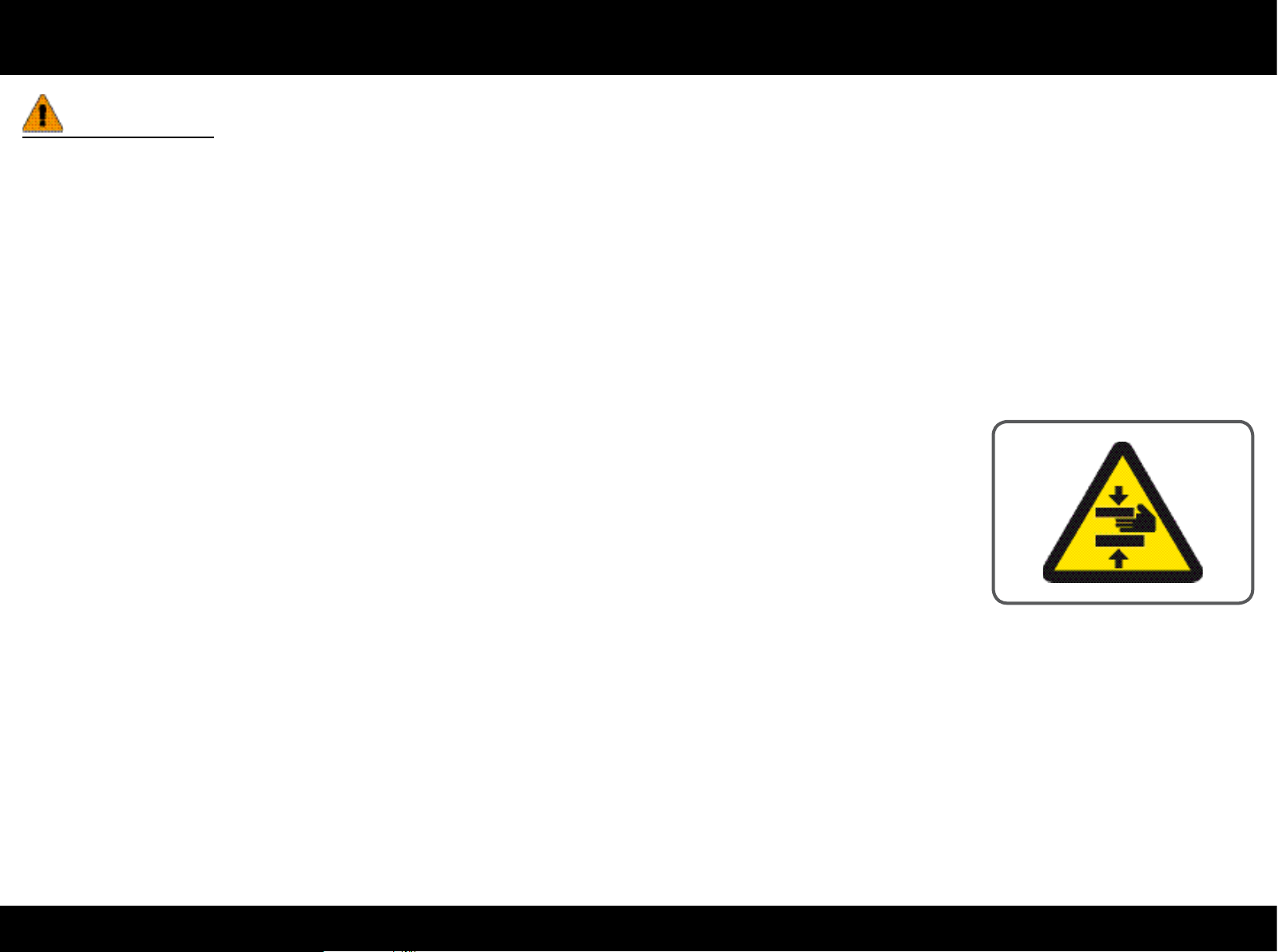
Pay particular attention to the parts of the equipment with labels indicating “BEWARE OF CRUSHING”.
7PLURIMA
Page 8
Identication of the manufacturer and equipment
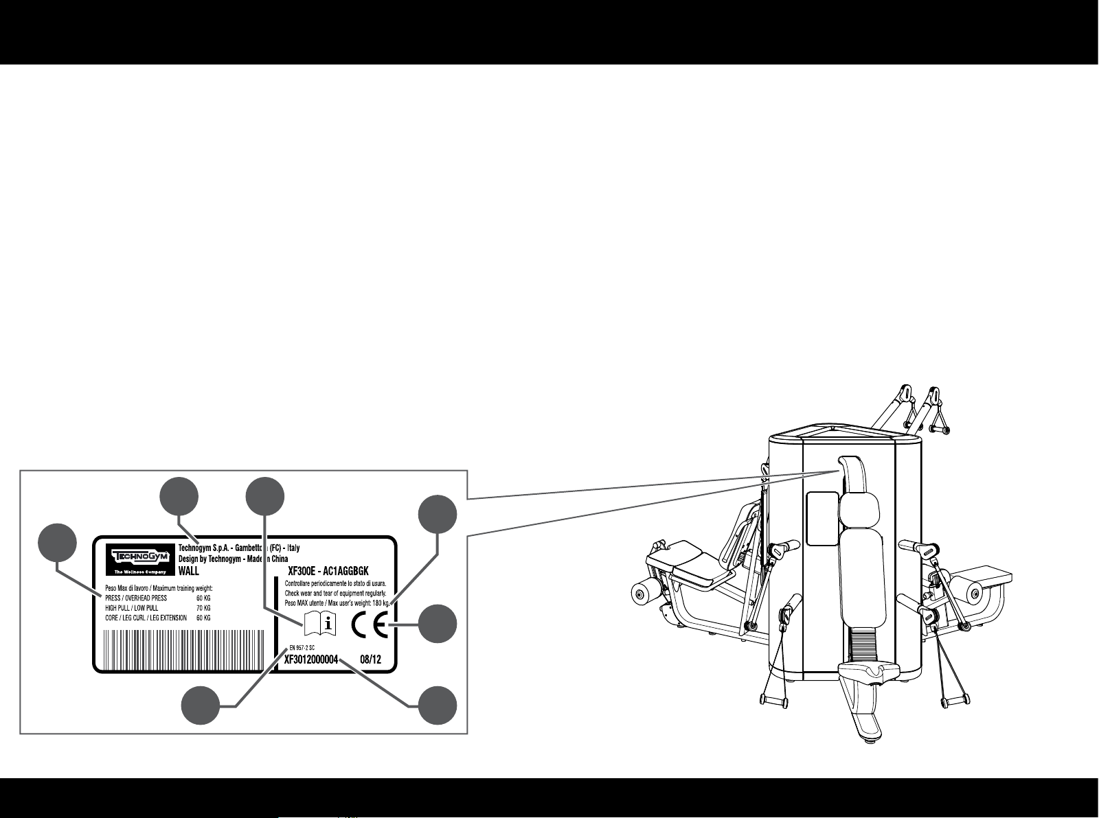
The label identifying the manufacturer and the equipment gives the following info:
A Manufacturer’s name and address
B CE Mark
C Serial number
D Warnings and maximum weight of the user
E Equipment classication
F Consultation of user manual required
The values given on the drawing are purely indicative; check the label on the equipment for accurate information.
D
A F
E
D
B
C
8PLURIMA
Page 9
Using the equipment
The equipment has no sharp corners.
All parts which come into contact with the user's body are suitably protected with rubber or padding.
The outside of the weight stack is covered by protective panels.
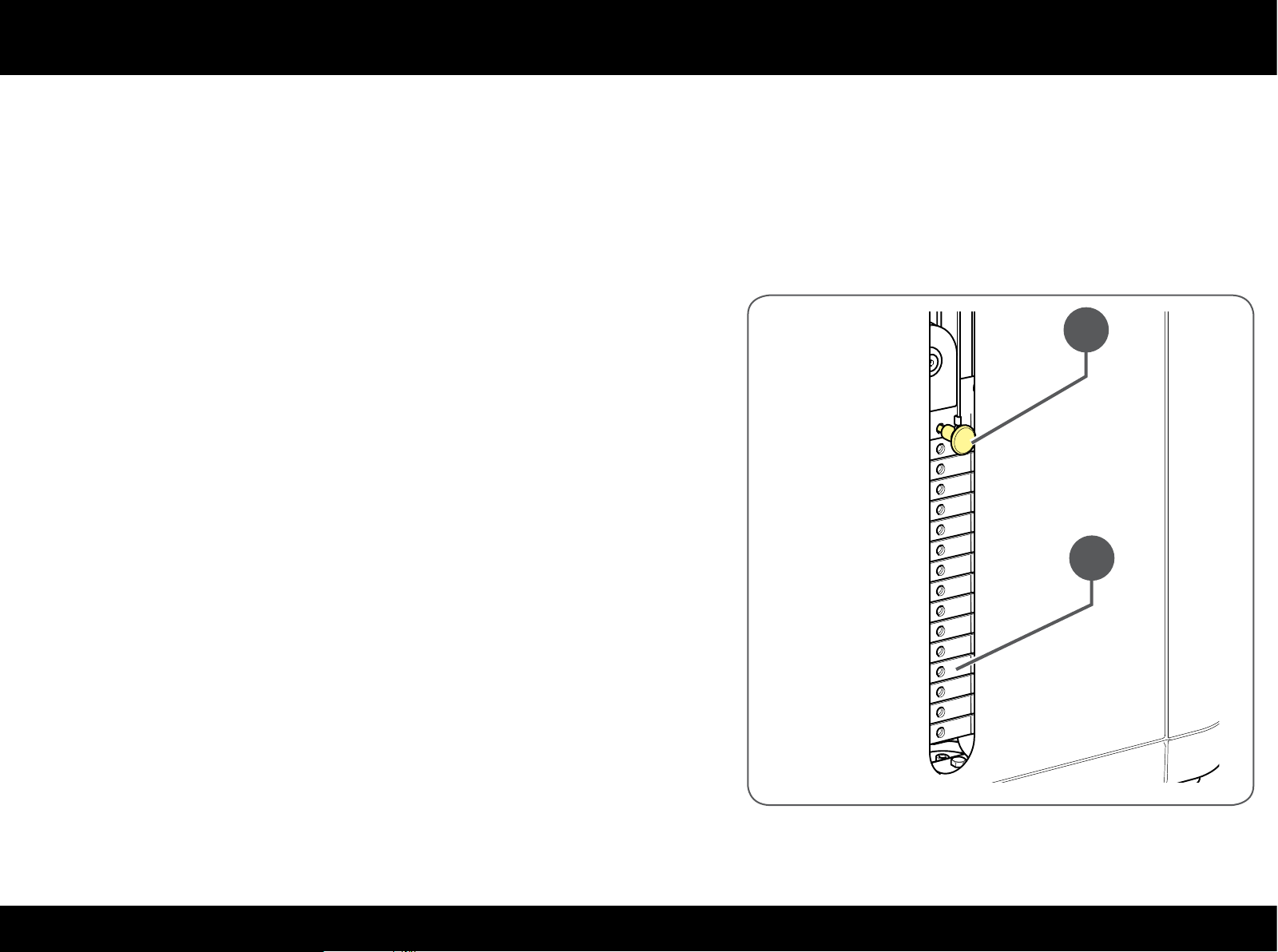
Weight stack: the weights (A), operated by the user, move along two guides by
means of a cable. A pin (B) is used to select the load and to adjust the extent
of the workout.
B
A
9PLURIMA
Page 10
Using the equipment
Only the main workouts are given below; for more info on how to use the product
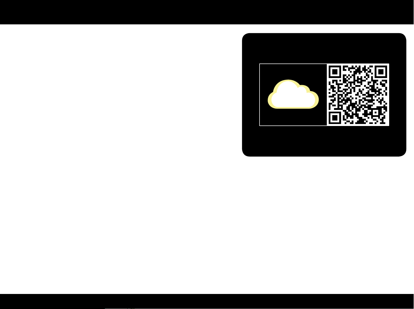
visit www.tg.com/plurima; or you can connect to the Plurima contents with the
QR Code printed on the label with the workouts on the product.
The QR Code (Quick Response Code) is a binary code that can be read by the
latest generation electronic devices: smart phone, tablet, mobile phone, laptop.
Specic digital contents correspond to each QR Code: link, web pages, audio les,
etc., pertaining to the object the code is given in. To view a QR Code you have to
download, free of charge, your preferred QR Reader application.
The QR Reader uses the camera of its own device to focus on the QR Code, read
and connect to the coded contents.
10PLURIMA
Page 11
Using the equipment
Core & Leg Extension/Curl
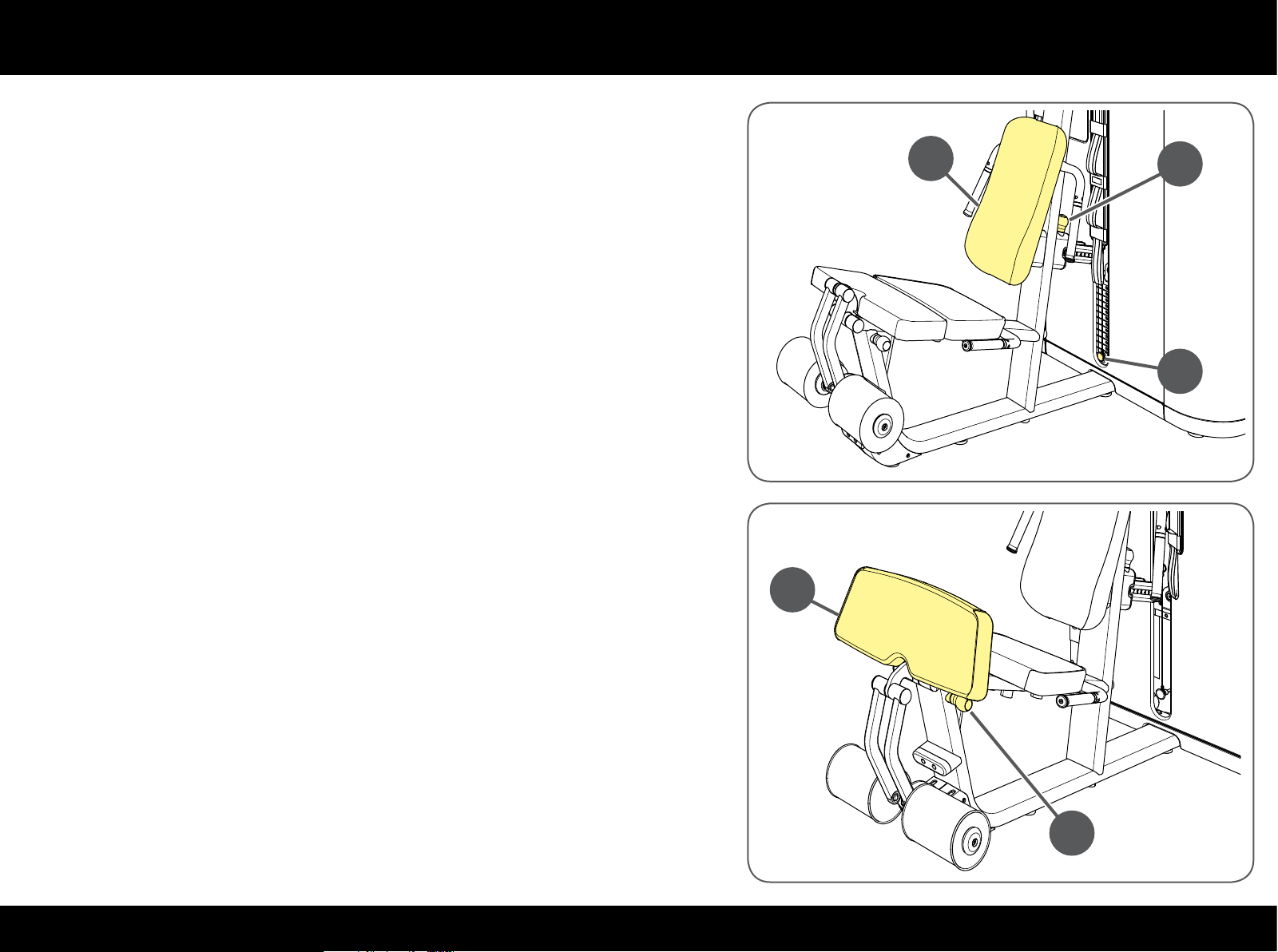
To adapt the seat to your height and centre your knees, move the backrest
forwards or backwards (A).
Pull the knob (B) behind the backrest and move the latter into the position
wanted; let the knob go to lock the backrest in position.
Select the workload with pin (C).
The front of the seat can be tipped vertically and used as a support. Pull the
knob (D) and lift the front part of the seat (E); be careful because while you
are tipping the padded part, the rollers move downwards.
E
A
B
C
D
11PLURIMA
Page 12
Using the equipment
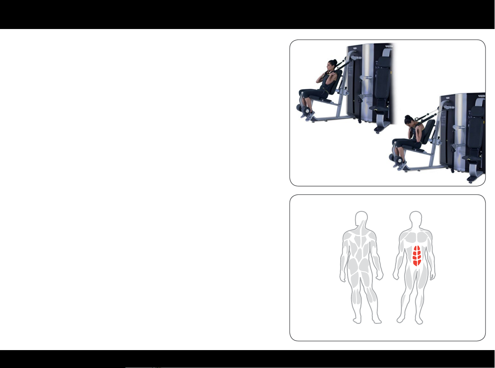
Sit with shins fully supported against the rollers, holding the straps securely
over the shoulders.
Pull the straps and ex through the abdominals to crunch, trying to bring your
breast bone close to your pelvis.
Maintain control of the workload during the movement; during the return phase
the weight stack must not return completely to the rest position.
Maintain a smooth controlled speed; we recommend a slower speed during the
return phase than during the approach phase.
At the end of the exercise, lie back until the weight stack returns to the rest
position.
12PLURIMA
Page 13
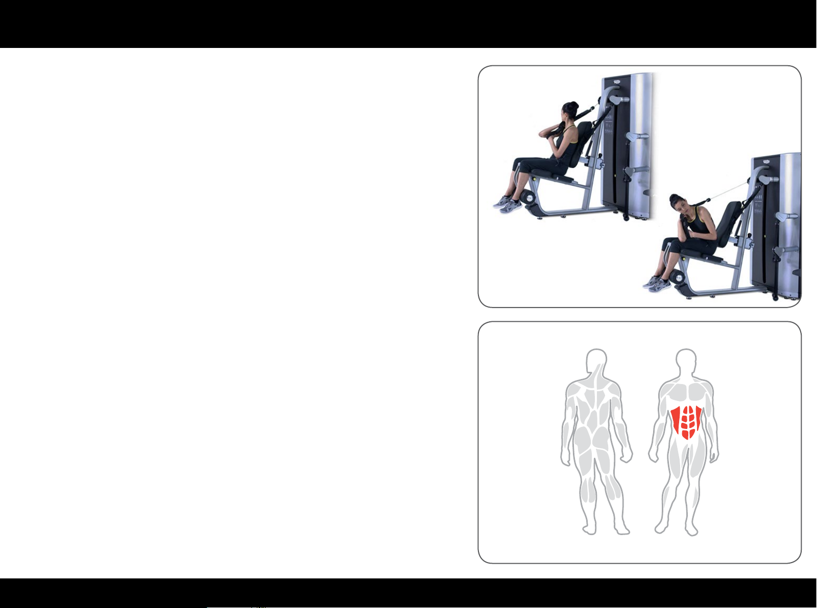
Using the equipment
Sit with feet unsupported, holding a strap over one shoulder.
Pull the strap and ex through the abdominals to crunch with your elbow facing
the opposite knee.
Maintain control of the workload during the movement; during the return phase
the weight stack must not return completely to the rest position.
Maintain a smooth controlled speed; we recommend a slower speed during the
return phase than during the approach phase.
At the end of the exercise, lie back until the weight stack returns to the rest
position.
13PLURIMA
Page 14
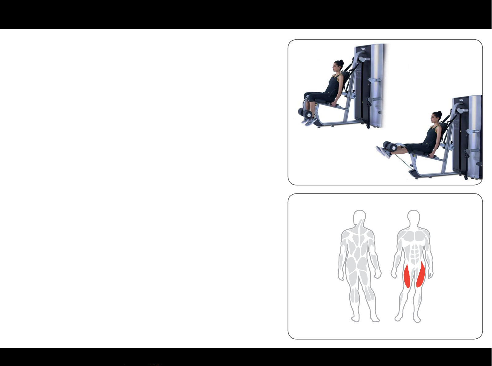
Using the equipment
Sit with shins fully supported against the rollers.
Rest your back at against the backrest.
Hold the side handgrips for greater stability during the movement.
Extend through the knees together with a slow and controlled movement.
Flex the knee to lower the rollers back to starting position.
Maintain control of the workload during the movement; during the return phase
the weight stack must not return completely to the rest position.
14PLURIMA
Page 15
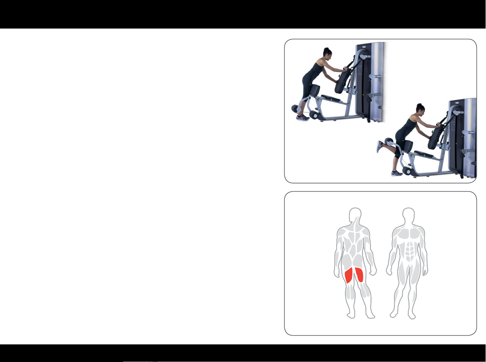
Using the equipment
Vertically lift the front part of the seat.
Stand with the back of one ankle behind the roller, keeping the other leg on the
oor slightly bent.
Put one hand against the backrest and hold the handgrip on the side of the
backrest with the other hand.
Flex through the knee with a slow and controlled movement.
Maintain control of the workload during the movement; during the return phase
the weight stack must not return completely to the rest position.
15PLURIMA
Page 16
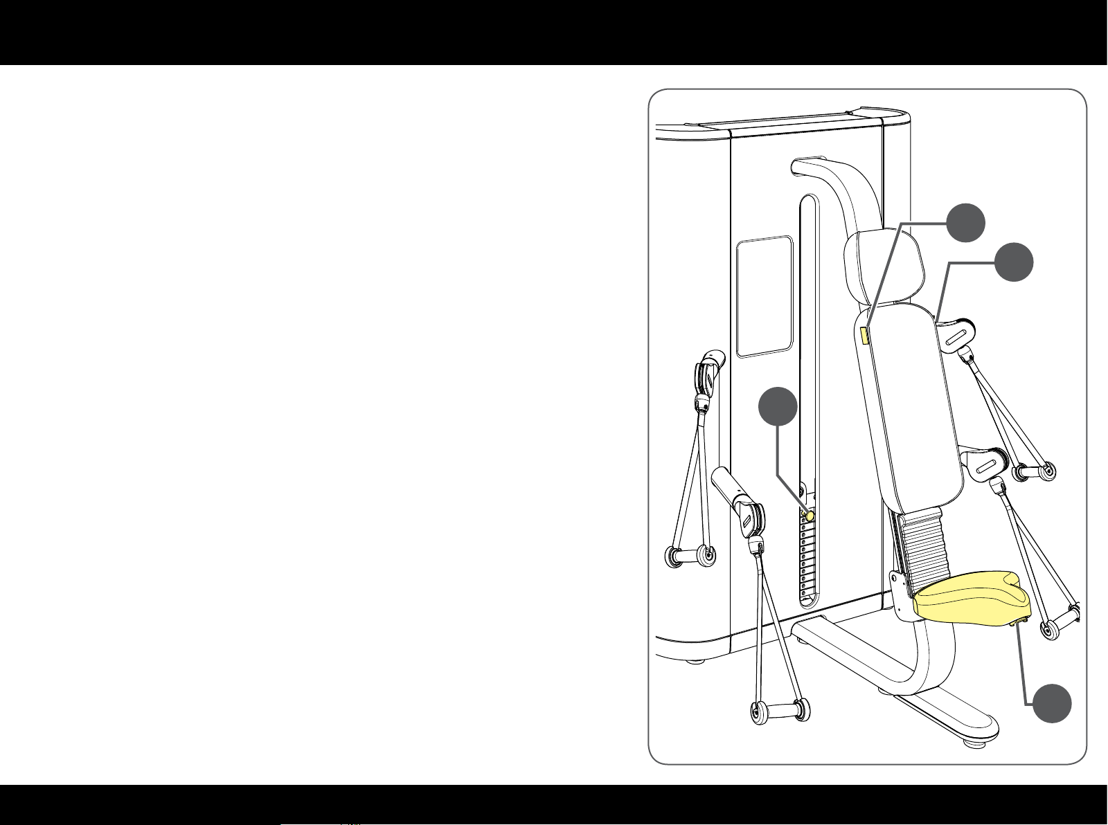
Using the equipment
Press & Overhead Press
Sit and adjust the seat with the lever (A) under the front of the seat itself.
Keep the lever up (A): the body weight is enough to lower the seat, but to raise
the seat you have to stand up.
When sitting with the arms along your sides, the shoulders must be in line with
the two yellow indicators (B) on the sides of the backrest.
Select the workload with pin (C).
Your feet should be rmly on the oor; open your legs for greater stability.
B
B
C
A
16PLURIMA
Page 17
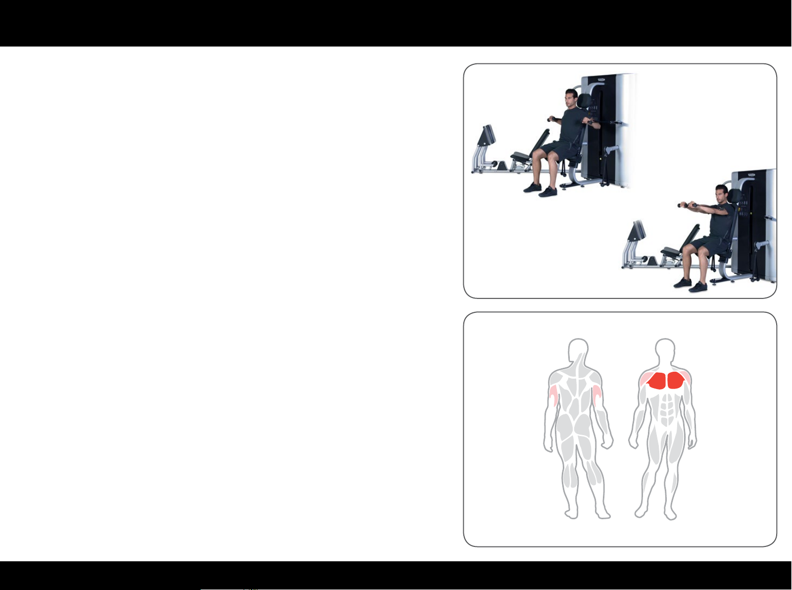
Using the equipment
Rest your back at against the backrest; hold the high handles, with the elbows
exed and in line with the shoulders, palms facing down.
Extend the arms in front of the chest simultaneously, without straining your
elbows; then return to the starting position.
Keep elbows, wrists and shoulders aligned while performing this exercise.
Maintain a smooth controlled speed; we recommend a slower speed during the
return phase than during the approach phase.
17PLURIMA
Page 18
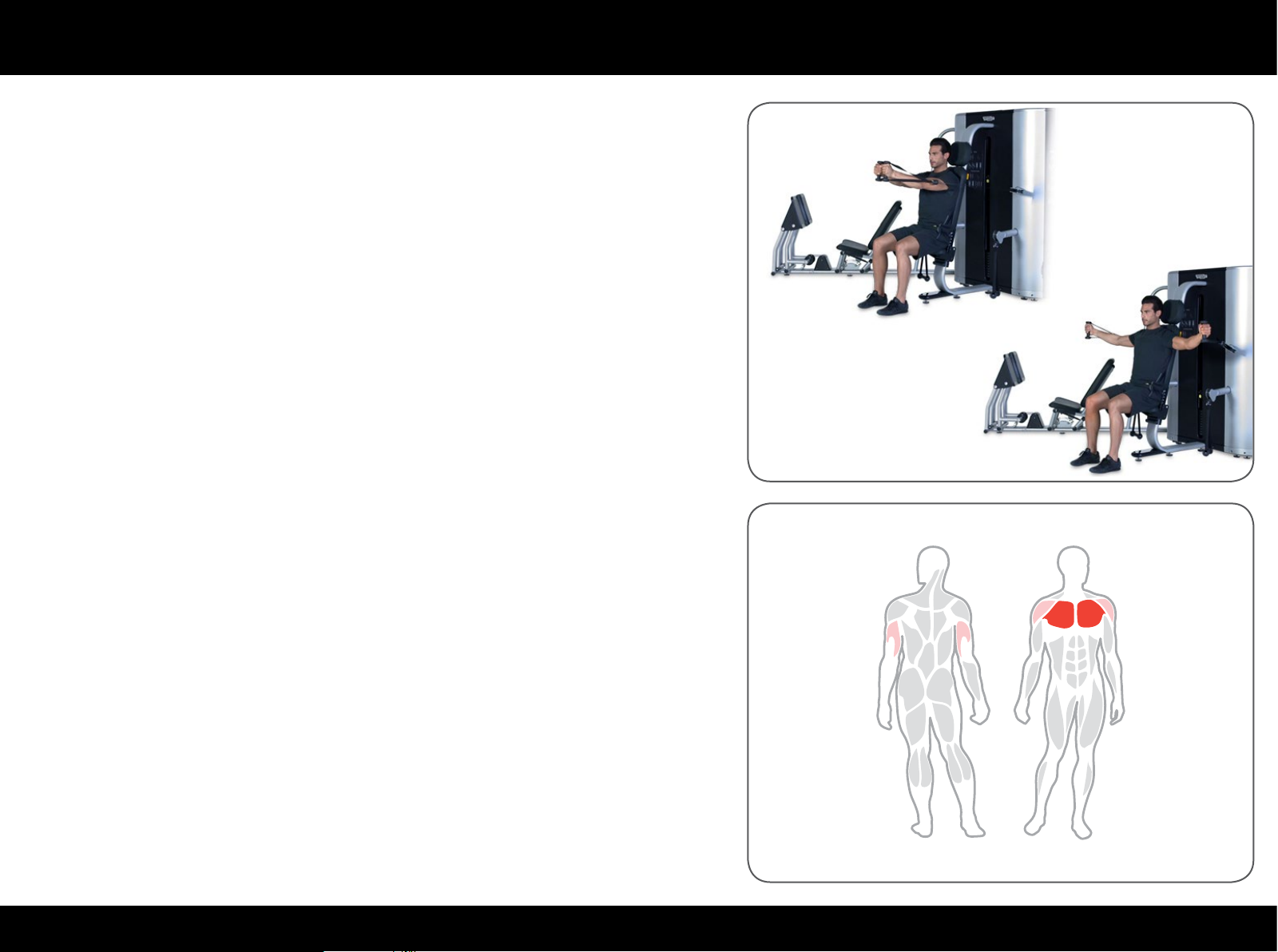
Using the equipment
Rest your back at against the backrest; hold the high handles, with the arms
out straight in front of your chest at shoulder height.
Open your arms outwards, keeping them straight; then bring them back in front
of the chest.
Maintain a smooth controlled speed; we recommend a slower speed during the
return phase than during the approach phase.
18PLURIMA
Page 19
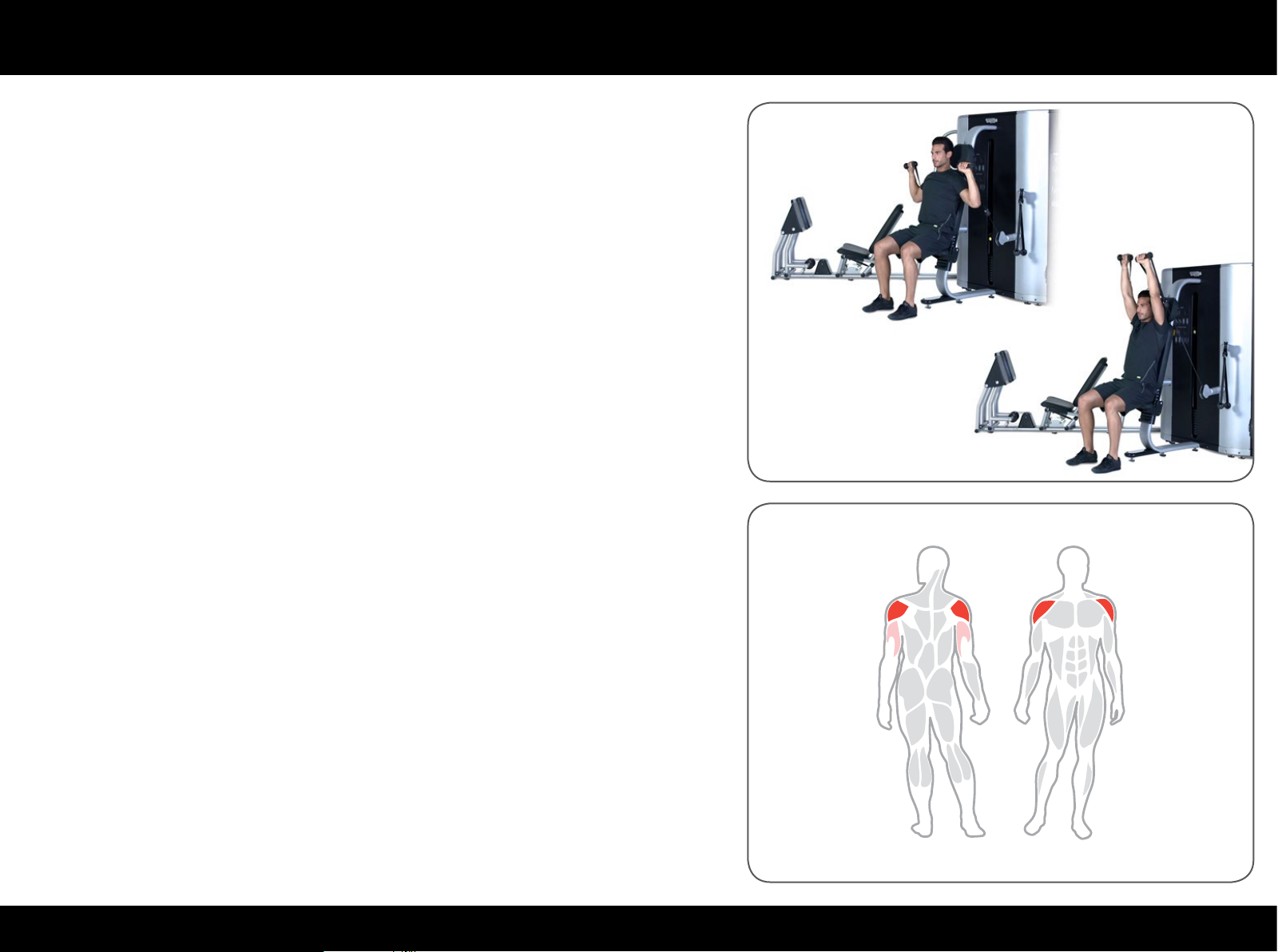
Using the equipment
Rest your back at against the backrest; hold the high handles, with the elbows
exed and in line with the shoulders, palms facing forwards.
Extend the arms overhead simultaneously, without straining your elbows; then
return to the starting position.
Keep elbows, wrists and shoulders aligned while performing this exercise.
Maintain a smooth controlled speed; we recommend a slower speed during the
return phase than during the approach phase.
19PLURIMA
Page 20
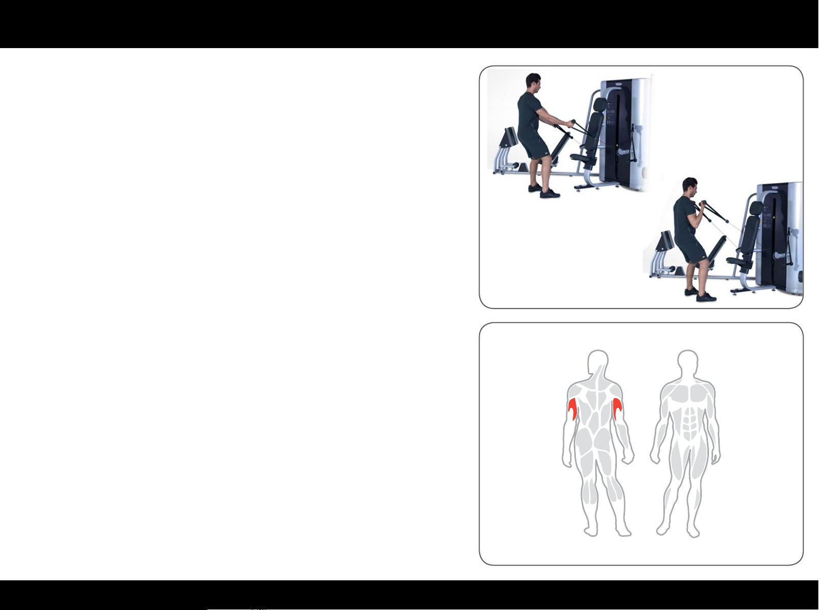
Using the equipment
Stand facing the equipment with your legs slightly apart for greater stability.
Hold the low handles with the arms straight downwards; palm facing up.
Flex at the elbows to curl the handles to the chest; then return to the starting
position.
Maintain a smooth controlled speed; we recommend a slower speed during the
return phase than during the approach phase.
20PLURIMA
Page 21
Using the equipment
High & Low Pull
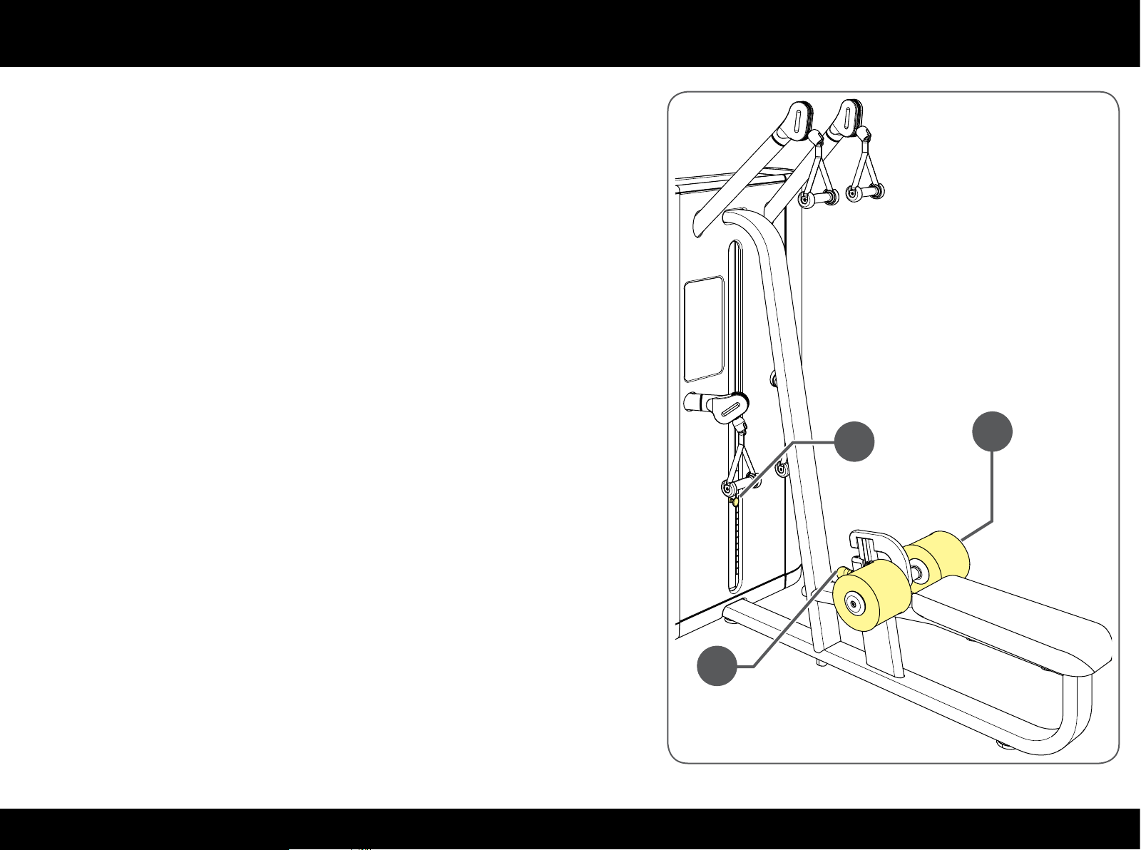
To adjust the height of the padded roller pull the knob (A) which is in front of the
rollers and lift or lower the roller lock (B).
Select the workload with pin (C).
A
C
B
21PLURIMA
Page 22
Using the equipment
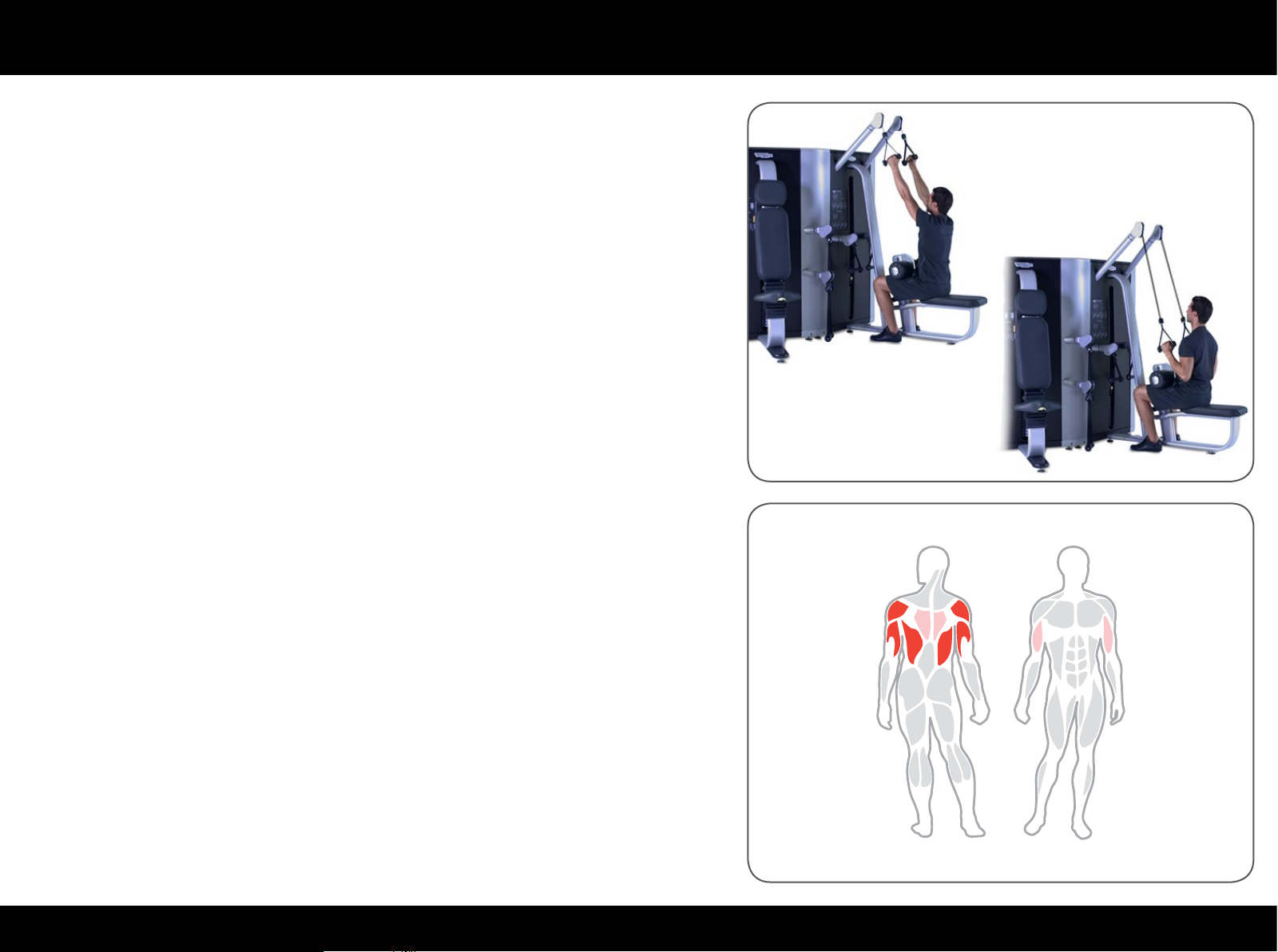
Hold the high handles, sit and put your thighs under the padded rollers; the feet
should be rmly on the oor, arms extended overhead and upper body erect.
Flex through the elbows to pull them down to the sides, squeezing the shoulder
blades and keeping the back straight. Then return to the starting position.
Maintain a smooth controlled speed; we recommend a slower speed during the
return phase than during the approach phase.
22PLURIMA
Page 23
Using the equipment
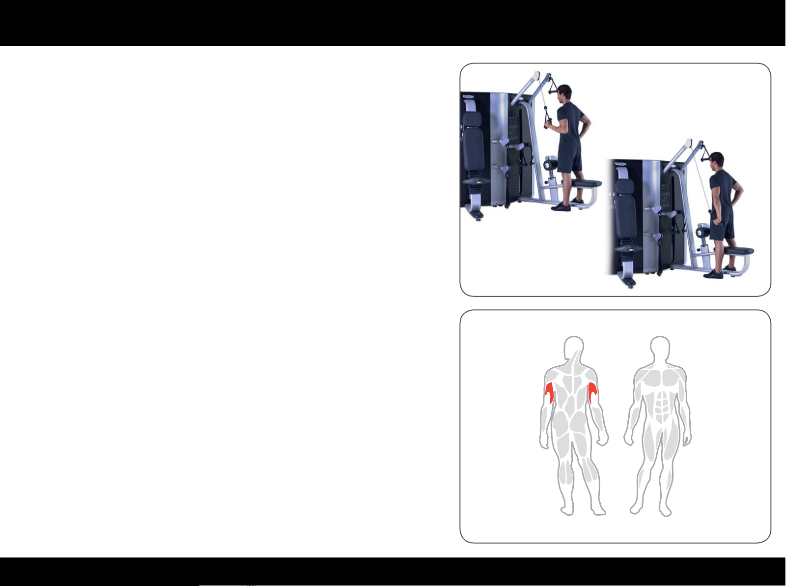
Stand facing the equipment, hold the high handle in one arm withe the elbow
exed and secure at the side of the body.
Keep the other arm down by your side.
Extend through the elbow pulling the handle toward the ground; then return to
the starting position.
Maintain a smooth controlled speed; we recommend a slower speed during the
return phase than during the approach phase.
Do this workout one arm at a time.
23PLURIMA
Page 24
Using the equipment
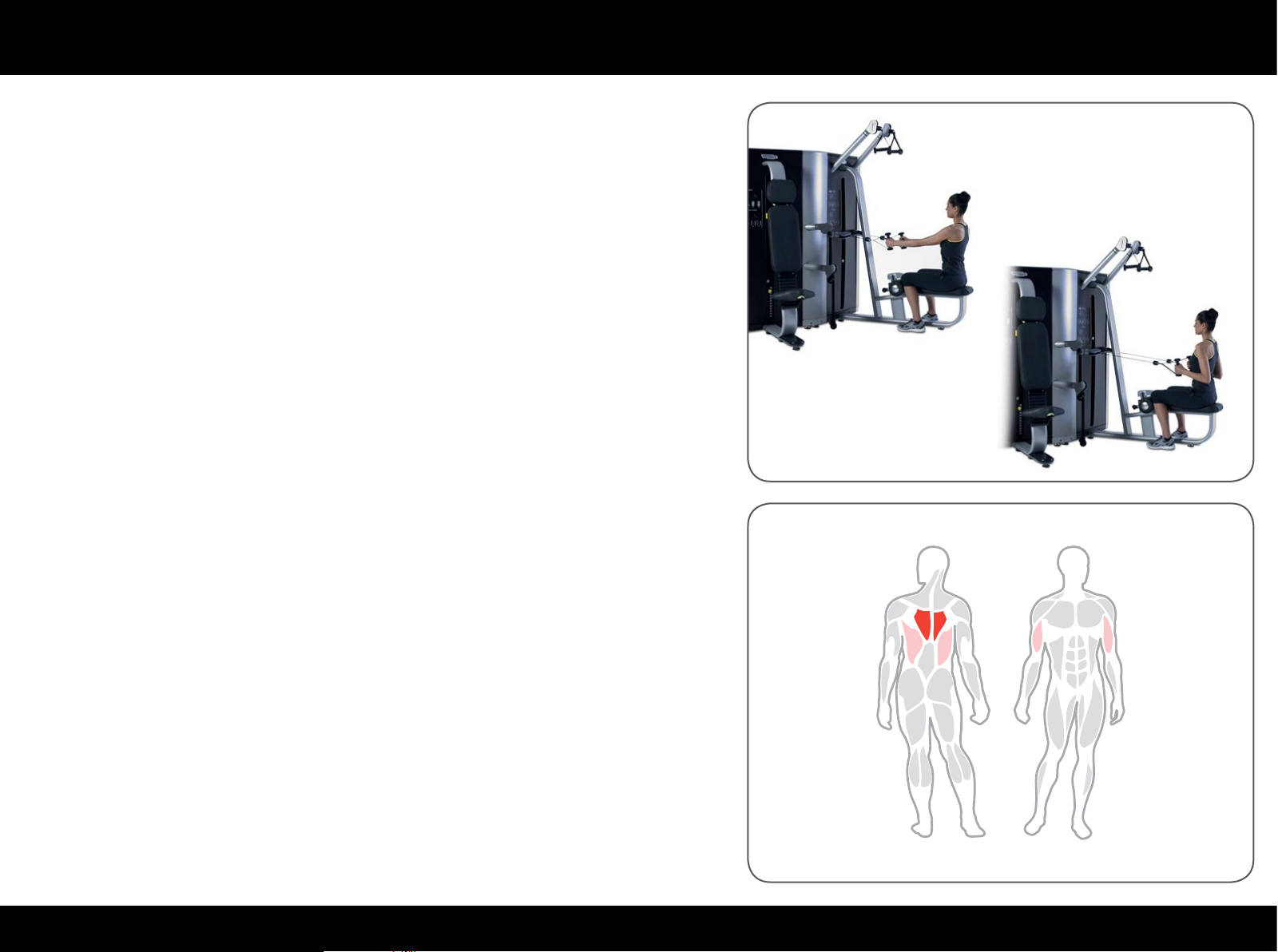
Bring the block of rollers right down into position 0.
Sit with the knees blocked against the padded rollers; the feet should be rmly
on the oor.
Hold the low handles with arms straight.
Flex through the elbow joints to pull the handles back, squeezing the shoulder
blades together, keeping the elbows down. Then return to the starting position.
Maintain a smooth controlled speed; we recommend a slower speed during the
return phase than during the approach phase.
24PLURIMA
Page 25
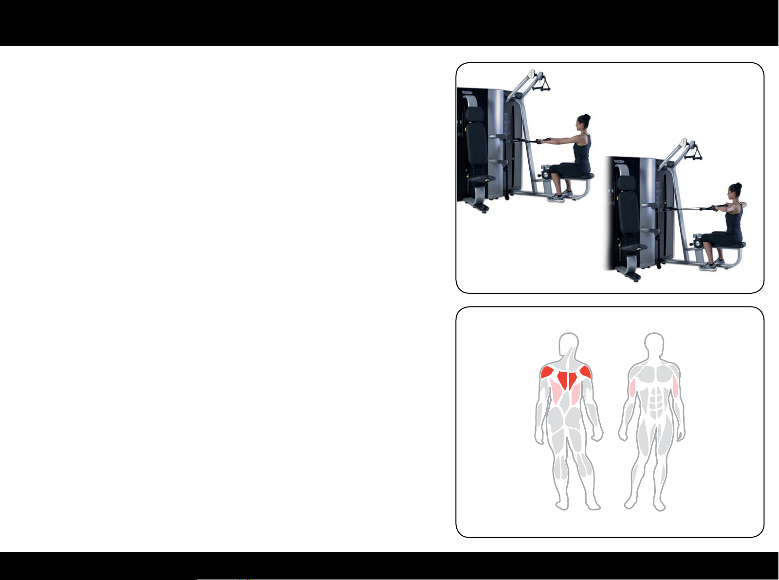
Using the equipment
Bring the block of rollers right down into position 0.
Sit with the knees blocked against the padded rollers; the feet should be rmly
on the oor.
Hold the low handles with arms straight; palms facing down.
Flex through the elbow joints to pull the handles back, bringing the elbows out
wide and in line with the shoulders. Then return to the starting position.
Maintain a smooth controlled speed; we recommend a slower speed during the
return phase than during the approach phase.
25PLURIMA
Page 26
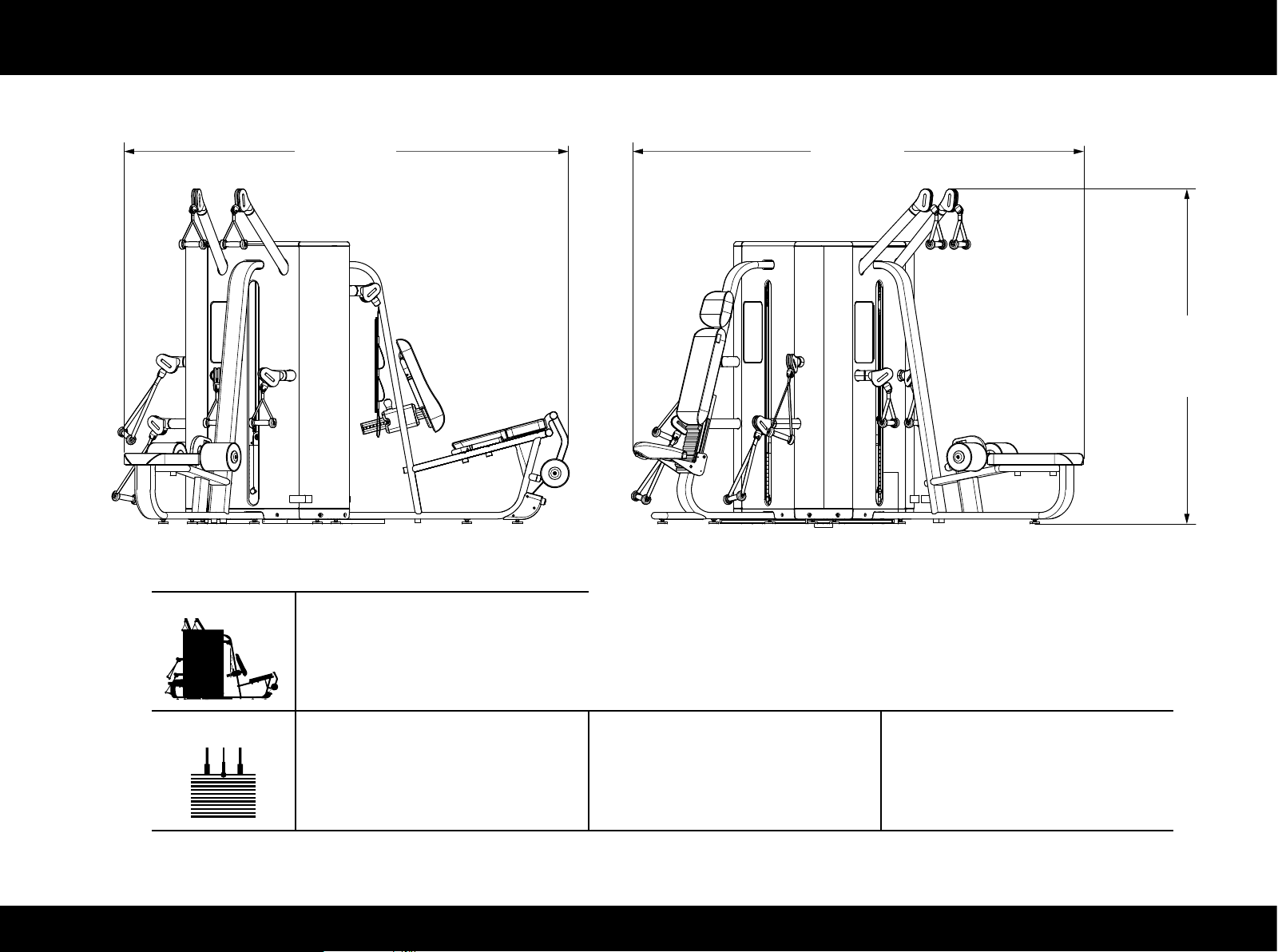
Technical data
2717 mm
(107 in)
2760 mm
(109 in)
(81 in)
2055 mm
Tower MF25
605 kg (1334 lb)
Core & Leg Extension/Curl Press & Overhead Press High & Low Pull
60 kg (120 lb) 60 kg (120 lb) 70 kg (140 lb)
26PLURIMA
Page 27
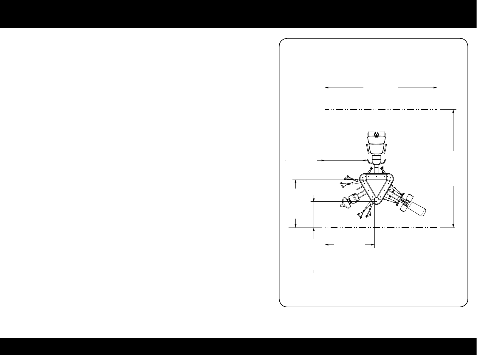
Place of installation
To ensure safe, comfortable and eective use of the equipment, the place of
installation must comply with certain specic requirements; in particular, before
choosing where to install the equipment we recommend that you check that
the following conditions are met:
- a temperature between +10°C and +25°C;
- sucient ventilation to maintain a humidity level between 20% and 90%,
when the equipment is in use;
- sucient lighting to make the area a safe and relaxing place to workout;
- a at, stable and vibration-free oor surface, with sucient load bearing
capacity for the weight to be borne;
- sucient clearance on all sides of the unit, taking into account its maximum
dimensions when in use, to ensure safety; the minimum distance from
1187 mm
(47 in)
3600 mm
(142 in)
(150 in)
3800 mm
permanent objects is given on the drawing.
If the equipment is to be installed in a public recreation area, the place of
installation must comply with all the requirements of the regulations currently
in force.
(61 in)
1544 mm
(33 in)
841 mm
1593 mm
(63 in)
27PLURIMA
Page 28
Place of installation
W
The equipment must be installed and used in a place where access and supervision are specically controlled by the owner.
When installing the equipment, use suitable personal protective equipment.
Install the equipment exactly where it is going to be used because its weight and size make it dicult to shift around.
28PLURIMA
Page 29
Lifting and moving the equipment
Because of its size and weight the equipment cannot be moved as is; it has to be dismantled and each component moved separately.
To assemble please refer to the installation instructions; however, we suggest contacting the Technogym Technical Support Service.
W
Move the equipment very carefully, because it may become unstable and tip over.
When lifting or moving the equipment do not press against the panels protecting the weight stack.
29PLURIMA
Page 30
Routine maintenance
W
The safety of the equipment is assured only on the condition that it is carefully inspected every two weeks for any signs of damage
and/or wear.
Replace defective and worn components immediately, or alternatively remove the equipment from service.
The equipment should always be kept clean and free of dust, in compliance with good hygiene practice, especially if it is used in a gym or by
more than one person.
Use a moist cloth or a sponge and mild soap to clean the padded parts.
Wipe the outside of the equipment every week using a damp sponge.
W
Be careful not to rub too hard on the drawings and instructions shown on the labels.
Oiling the weight stack guide rails:
- use a soft cloth to remove any dust and oil residues from the guide rails;
- slightly dampen the cloth with the oil provided;
- using this cloth, apply a very thin layer of oil over the guides, taking care not to apply too much.
Call the Technogym Technical Support Service for instructions on any maintenance operations not described in this manual.
30PLURIMA
Page 31
Replacing the padded parts
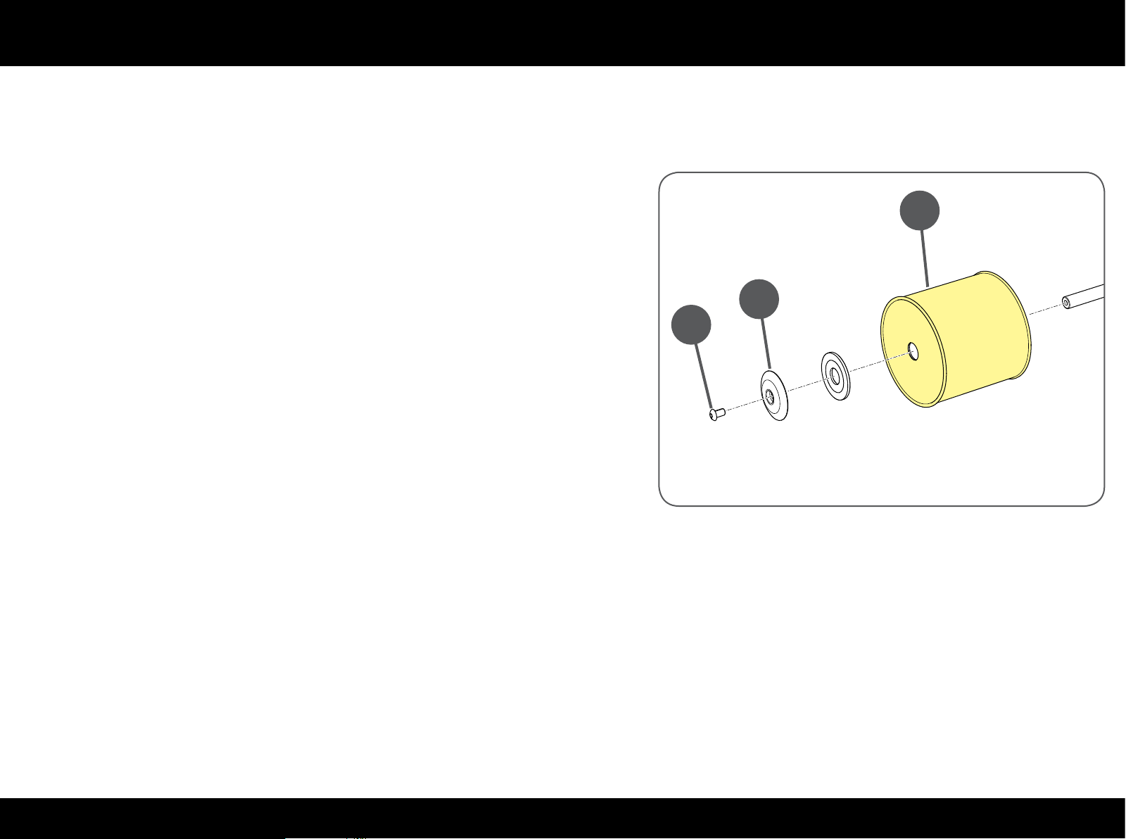
If any of the padding shows signs of wear, especially in the interests of hygiene, we recommend replacing it completely.
To replace the rollers, undo the screw (A), remove the cap (B) and pull the
roller (C) out.
C
B
A
31PLURIMA
Page 32
Replacing the padded parts
Core & Leg Extension/Curl
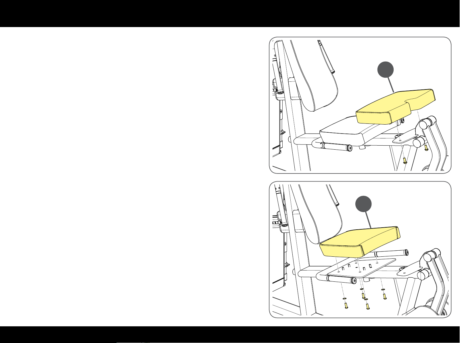
To replace the moving seat padding (A) unscrew the screws on the side opposite
the padding using a 6 mm ball spanner.
To replace the xed seat padding (B) unscrew the screws on the side opposite
the padding using a 6 mm T spanner.
A
B
32PLURIMA
Page 33
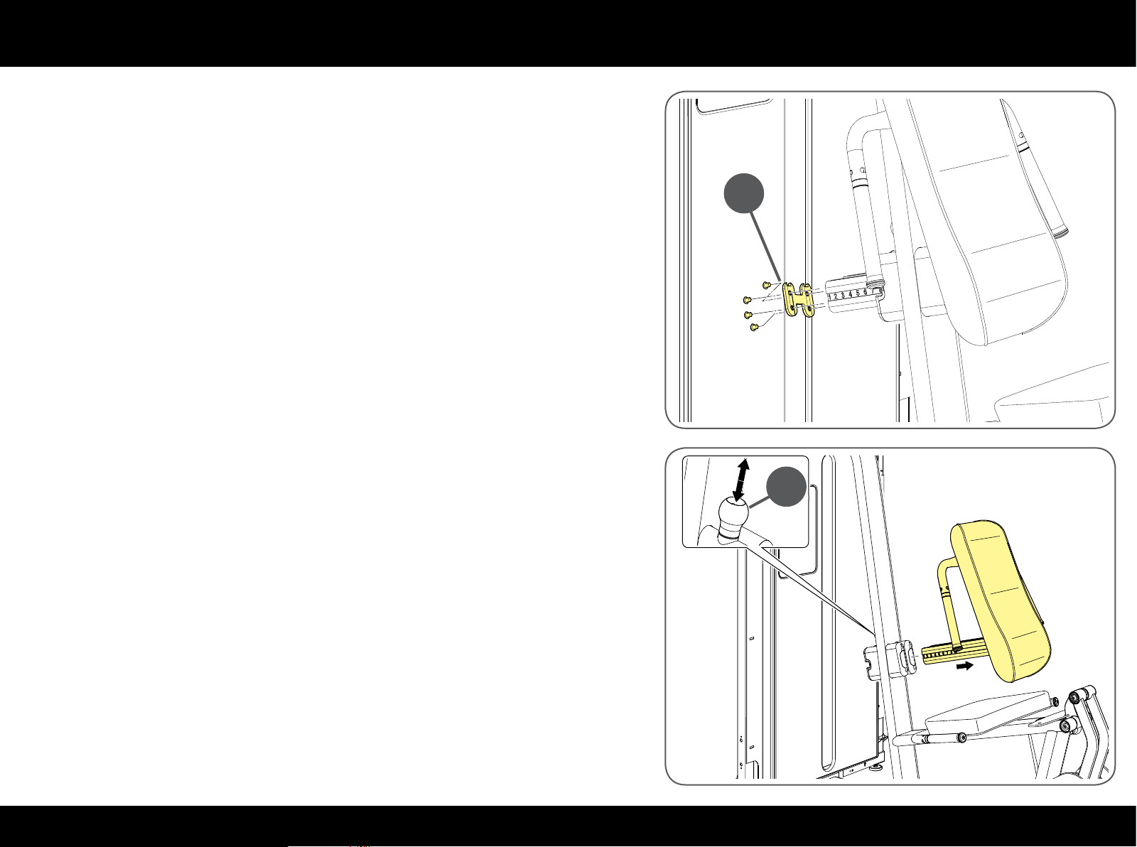
Replacing the padded parts
To replace the backrest padding unscrew the cap (C) with a 5 mm T spanner.
C
Pull the knob (D) and remove the whole backrest.
D
33PLURIMA
Page 34
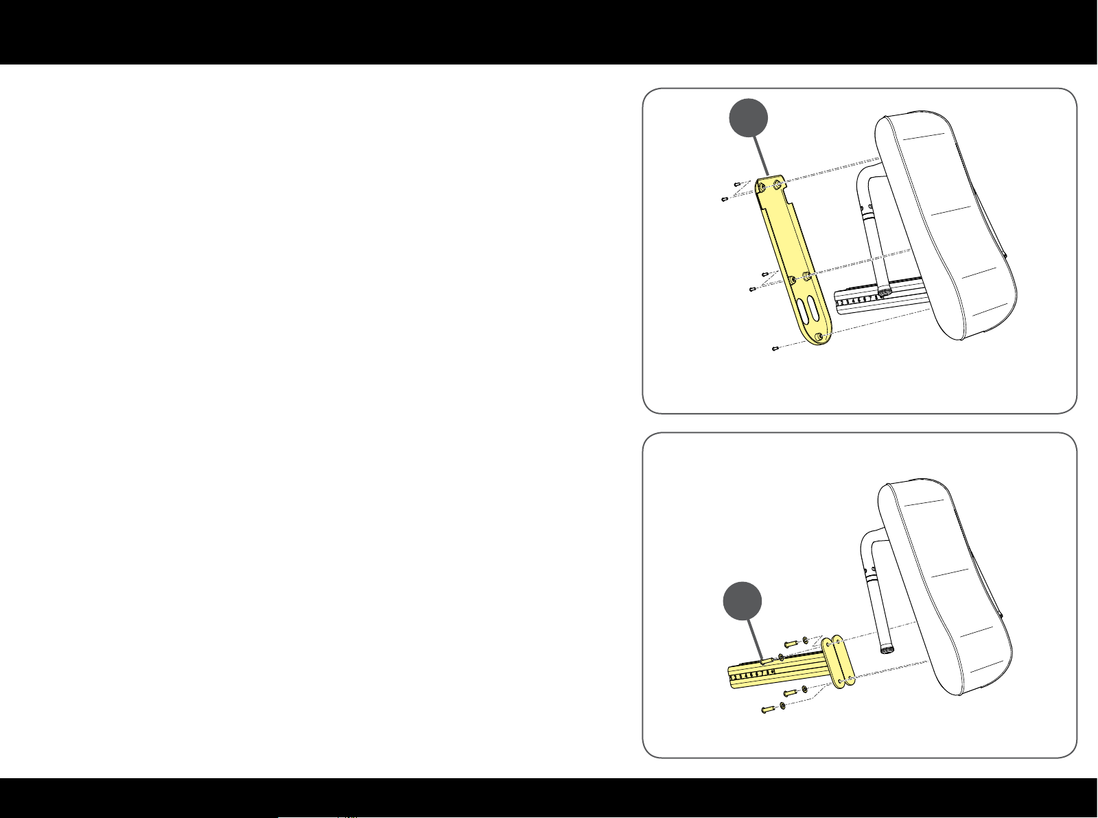
Replacing the padded parts
Remove the cover (E) with a 4 mm T spanner.
E
Remove the numbered bars (F) with a 6 mm L-ball spanner.
F
34PLURIMA
Page 35
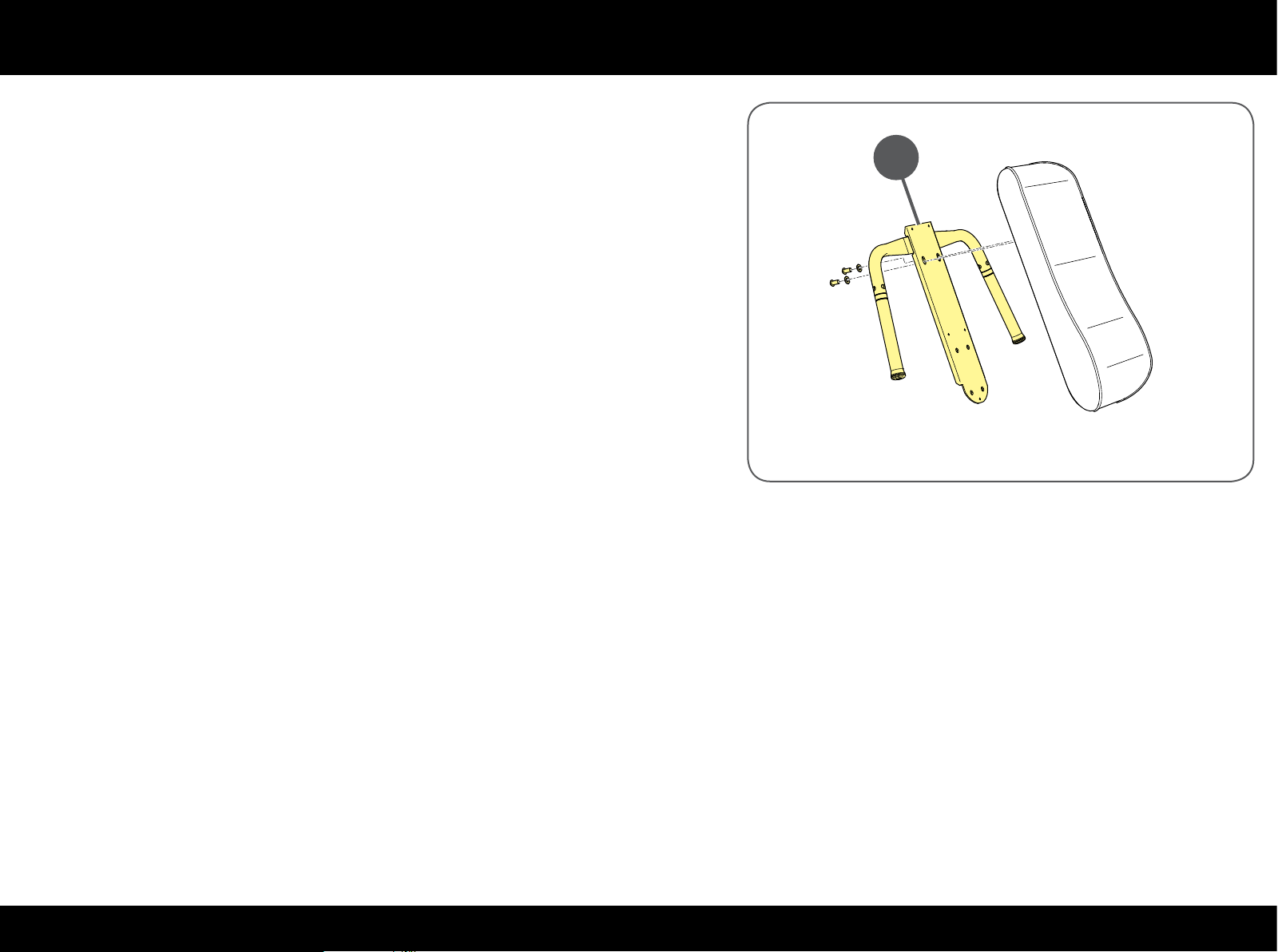
Replacing the padded parts
Remove the frame (G) from the backrest padding with a 6 mm T spanner.
G
35PLURIMA
Page 36
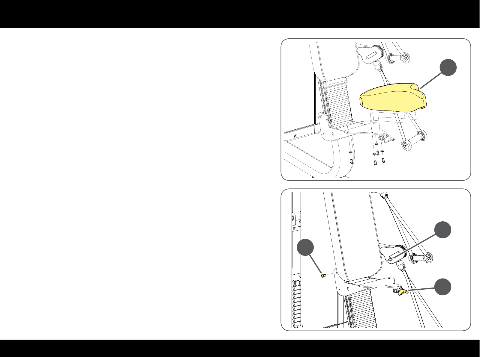
Replacing the padded parts
Press & Overhead Press
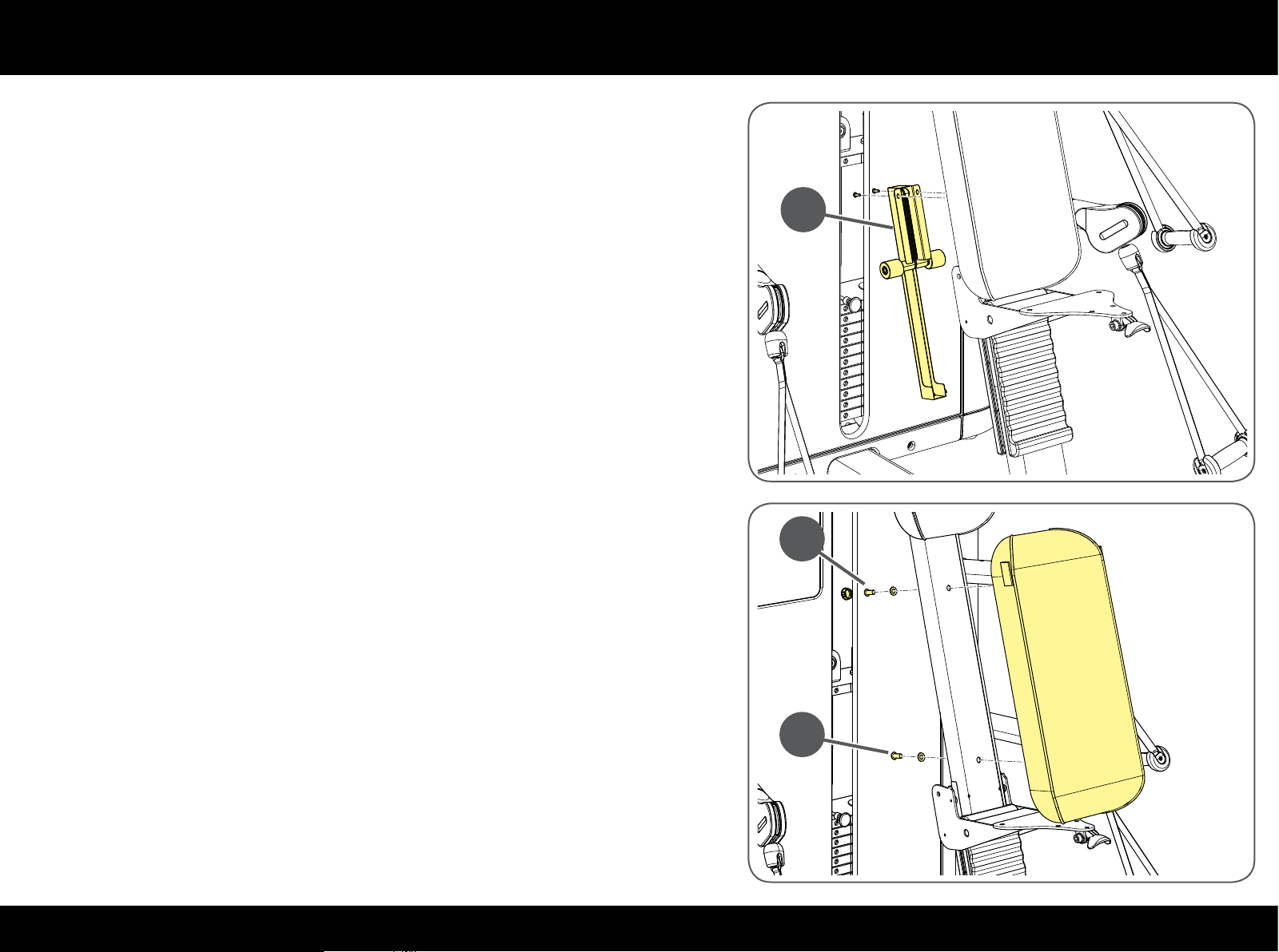
To replace the seat padding (A) unscrew the screws on the side opposite the
padding using a 5 mm T spanner.
To replace the backrest padding, pull the lever (B) and lift the seat.
Undo the screws (C) with a 6 mm T spanner.
A
C
C
B
36PLURIMA
Page 37
Replacing the padded parts
Remove the spring device (D) with a Phillips screwdriver.
D
Remove the cap covering the hole and unscrew the screws (E) with a 6 mm T
spanner.
E
E
37PLURIMA
Page 38
Replacing the padded parts
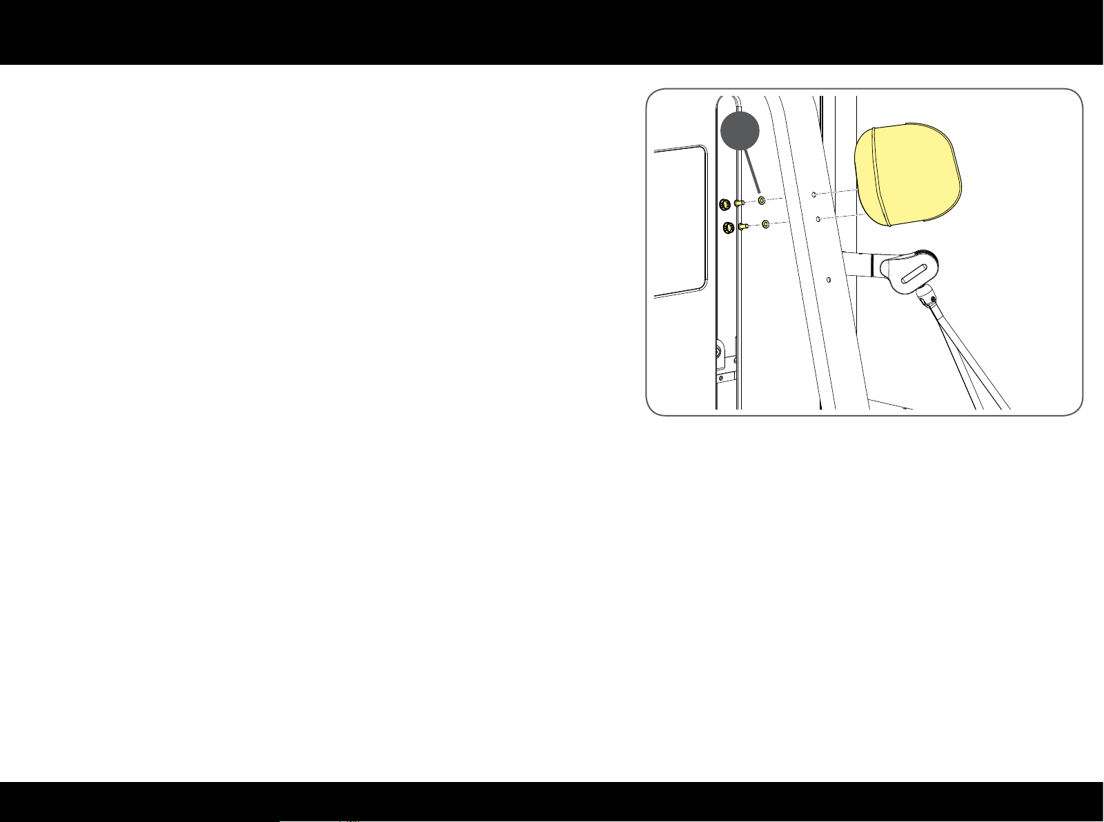
To replace the headrest padding, remove the caps covering the holes and undo
the screws (F) with a 6 mm T spanner.
F
38PLURIMA
Page 39
Replacing the padded parts
High & Low Pull
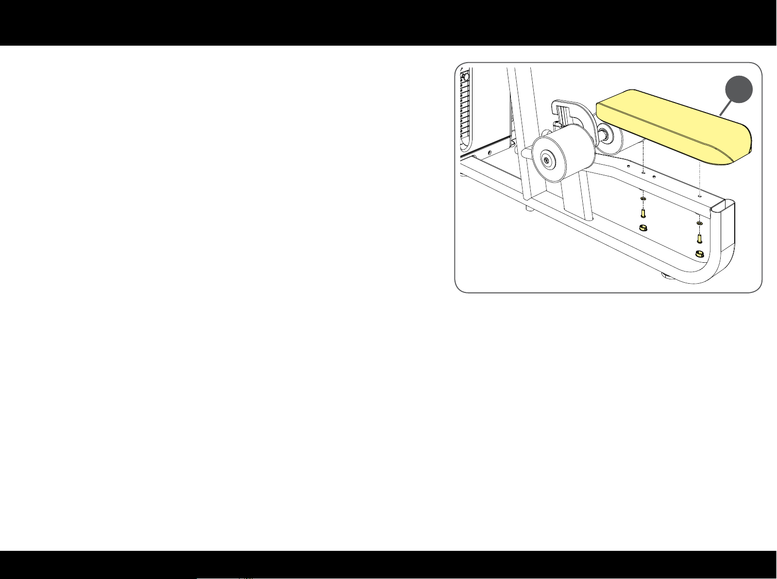
To replace seat padding (A) remove the caps covering the holes and undo the
screws on the side opposite the padding with a 6 mm T spanner.
A
39PLURIMA
Page 40
Replacing handles and straps
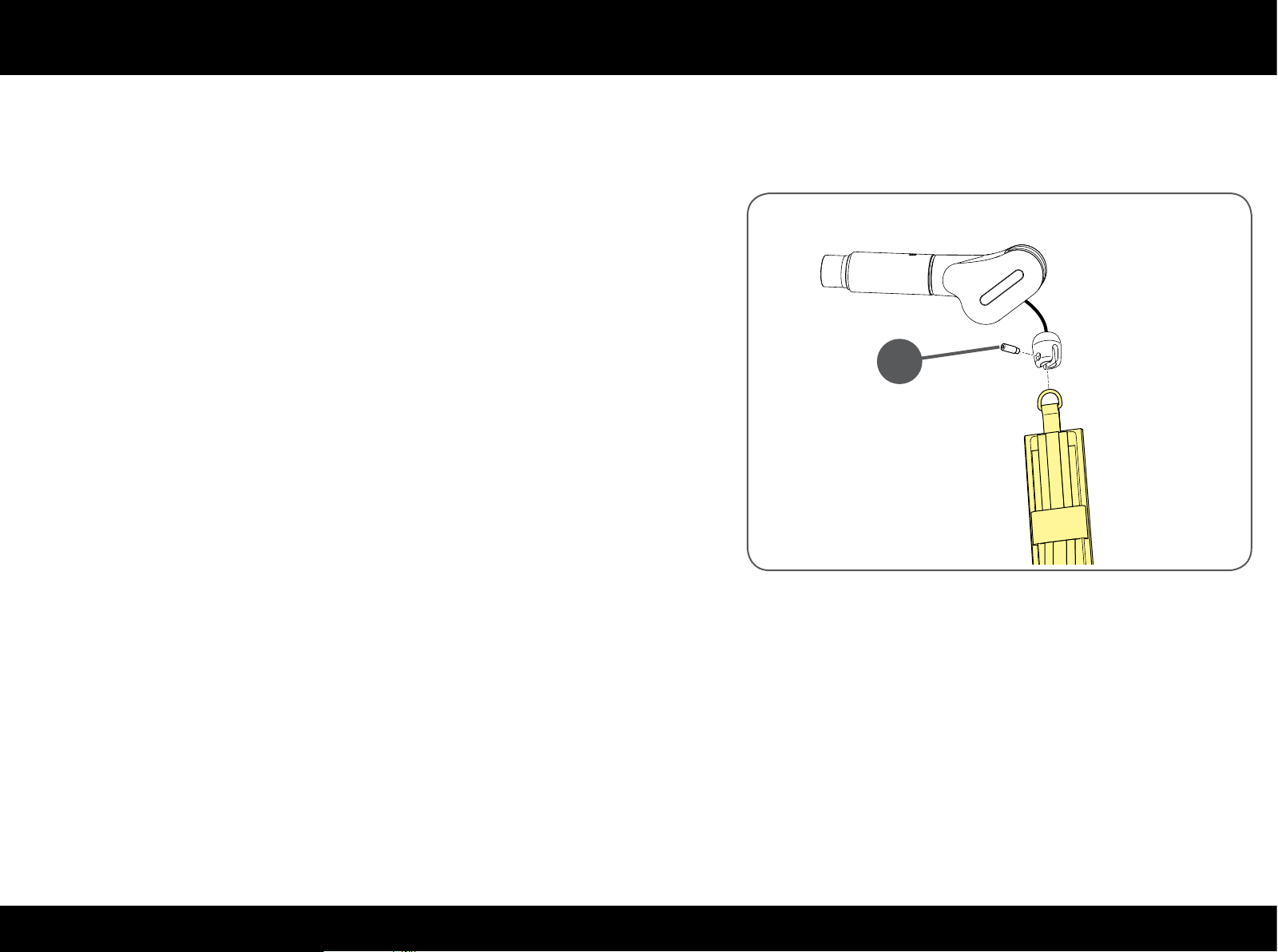
If the straps and handles show signs of wear, especially in the interests of hygiene, we recommend replacing it completely.
Core & Leg Extension/Curl
To replace the 2 straps: unscrew the pin (A) with a 5 mm T spanner.
A
40PLURIMA
Page 41
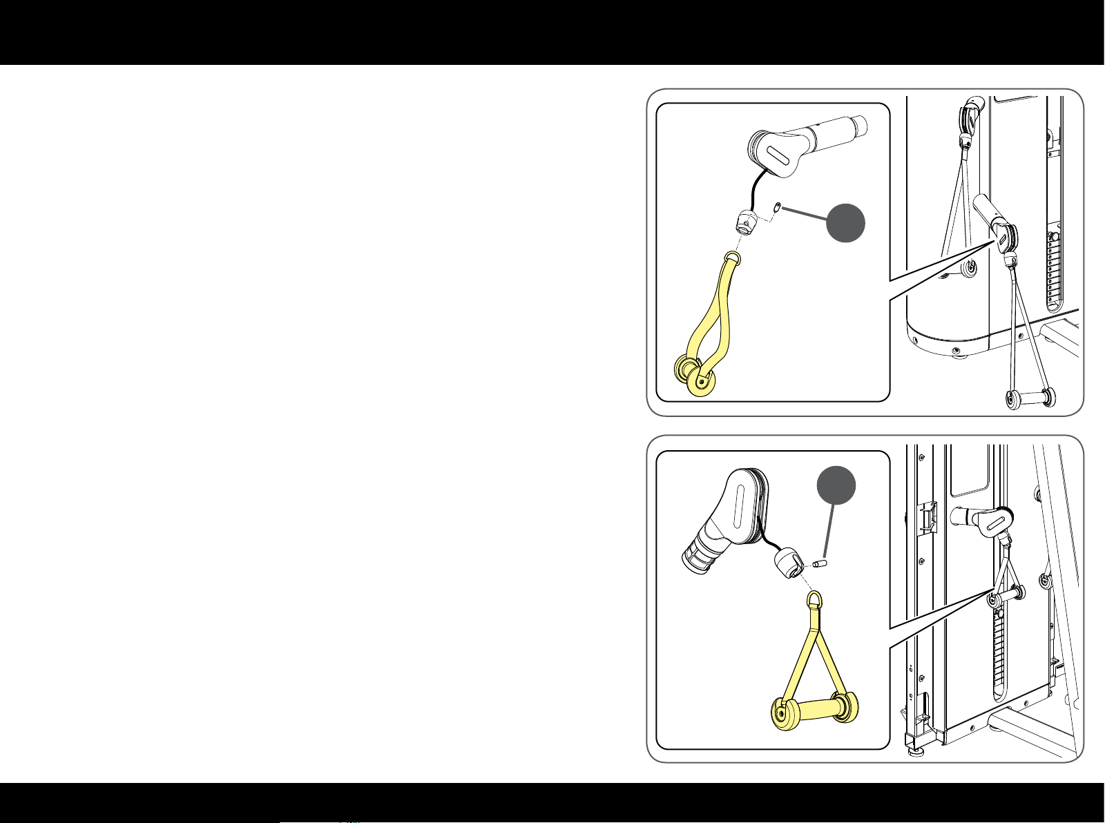
Replacing handles and straps
Press & Overhead Press
To replace the handles: unscrew the pin (B) with a 5 mm T spanner.
B
High & Low Pull
To replace the handles: unscrew the pin (C) with a 5 mm T spanner.
C
41PLURIMA
Page 42
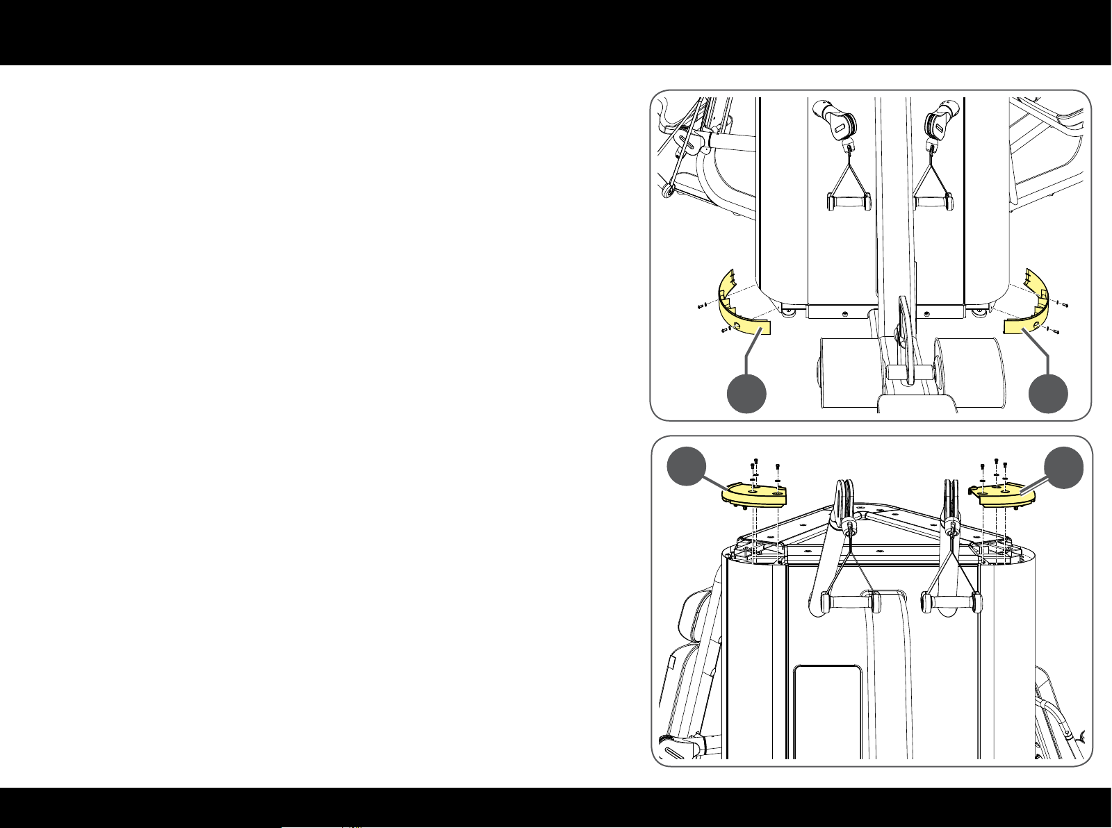
Reaching the inside parts
Remove the foot guards (A) with a 4 mm T spanner.
A A
A A
Remove the top angle pieces (B) with a 4 mm T spanner.
B B
B
42PLURIMA
Page 43
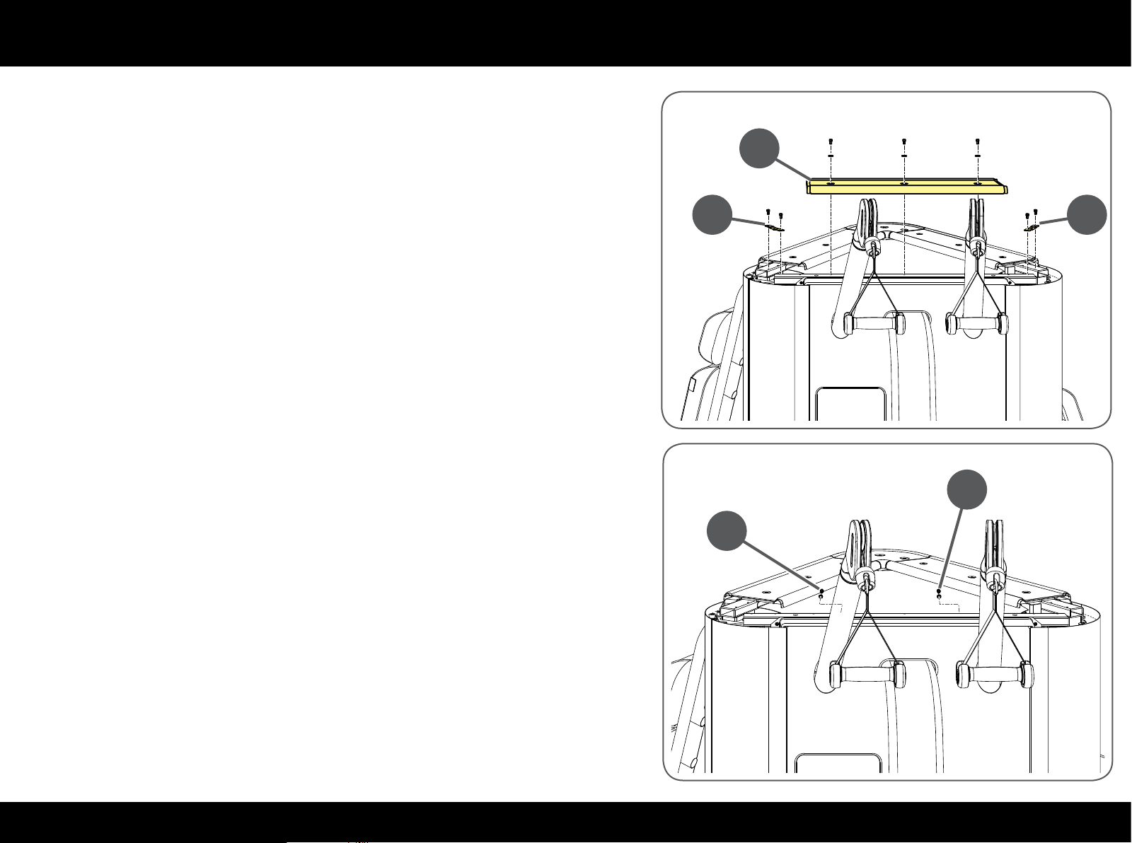
Reaching the inside parts
Remove the top guard (C) and the two xing plates (D).
C
D D
Remove the screws xing top cover (E).
E
E
43PLURIMA
Page 44
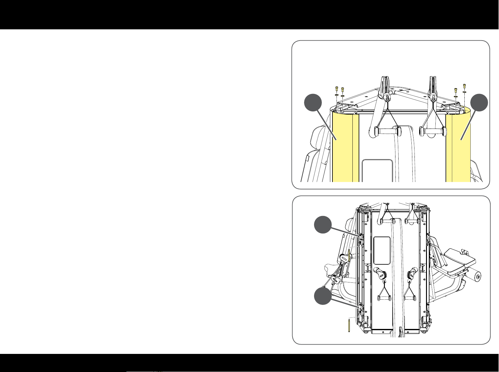
Reaching the inside parts
Remove the side guards (F).
Remove the pin from inside the hinges of the connection brackets (G).
F
F
G
G
44PLURIMA
Page 45
Reaching the inside parts
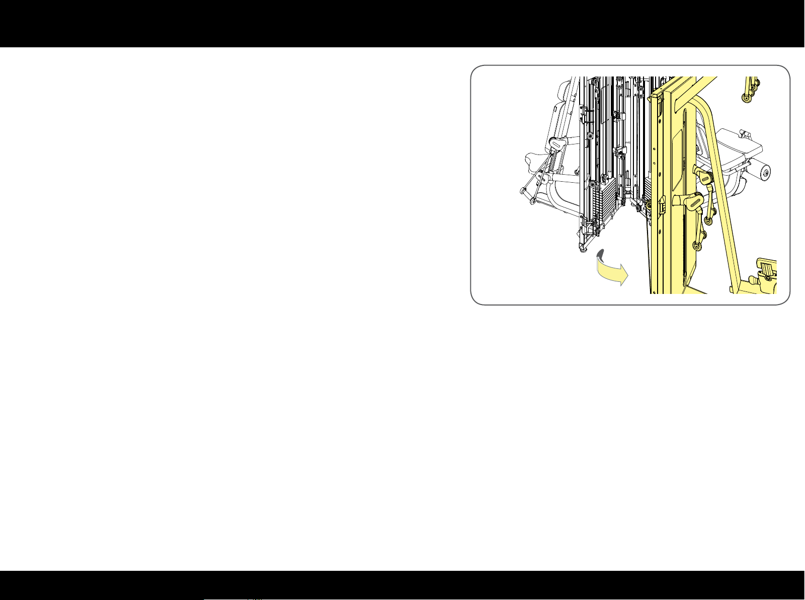
Turn the module until a person can get inside.
To reassemble the guards and prevent access to the inside parts, follow the
procedures described above in the opposite order.
45PLURIMA
Page 46
Replacing the cable
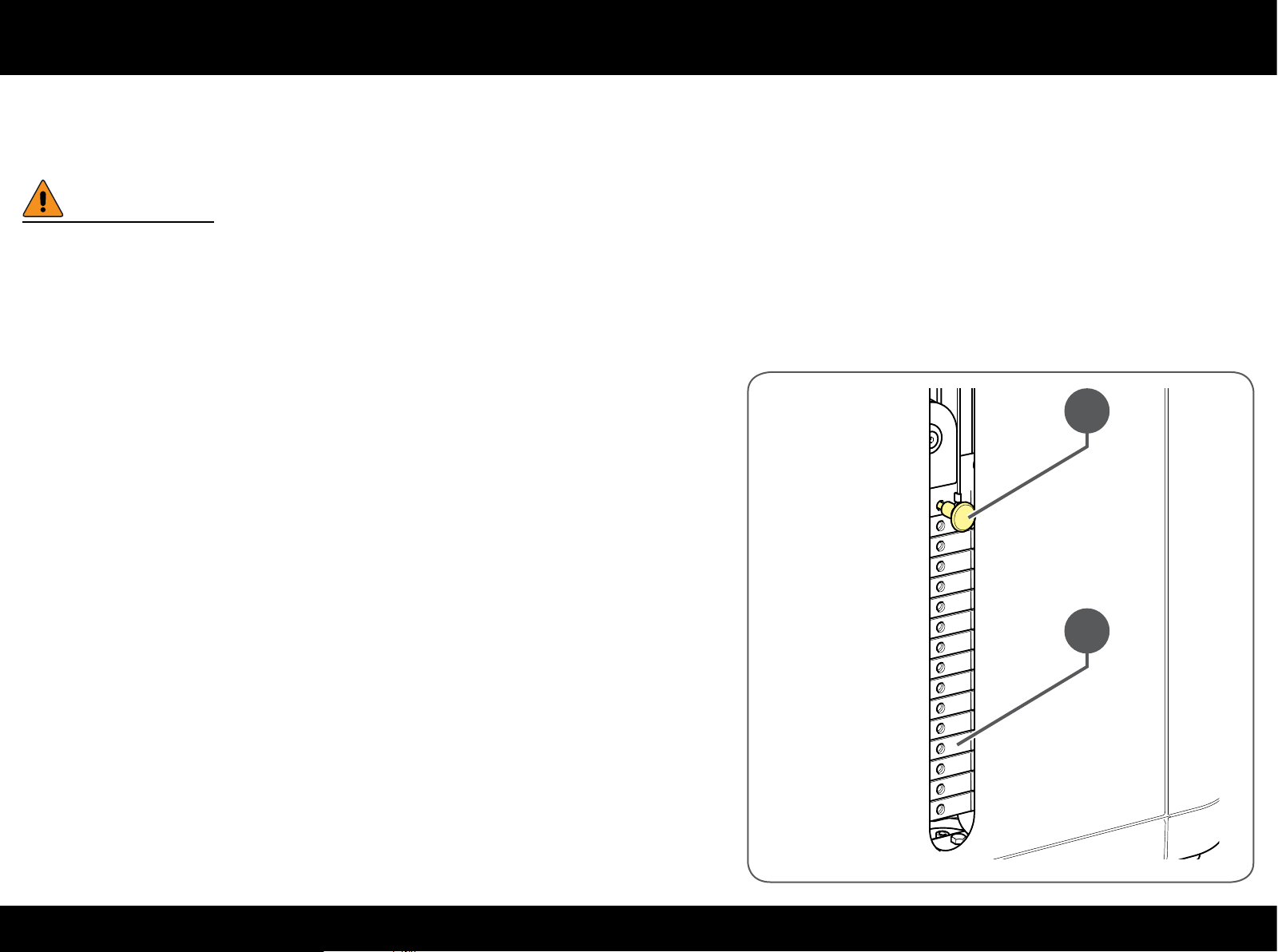
Cables must always be replaced at the rst sign of wear, even if only the outer rubber protection is worn.
Before continuing, remove the guards to reach the whole cable assembly as described in the "Reaching the internal parts" paragraph.
W
Carefully check the state of the cables once a month.
ALWAYS use cables supplied directly by Technogym.
Take the pin (A) out of the weight stack, lift the crosspiece (B), put the pin back
in to block the crosspiece at the top. This will loosen the cable.
B
A
46PLURIMA
Page 47
Replacing the cable
Core & Leg Extension/Curl
Replacing the lever cable
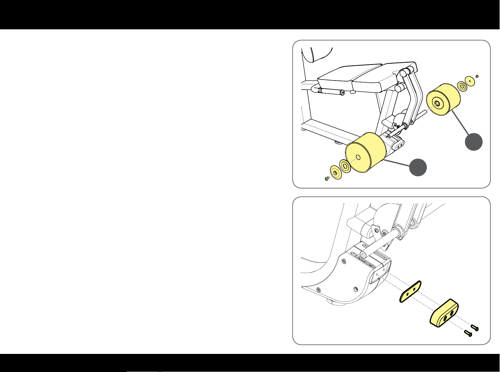
Each lever has one cable. The cables of the two levers are replaced in the same
way.
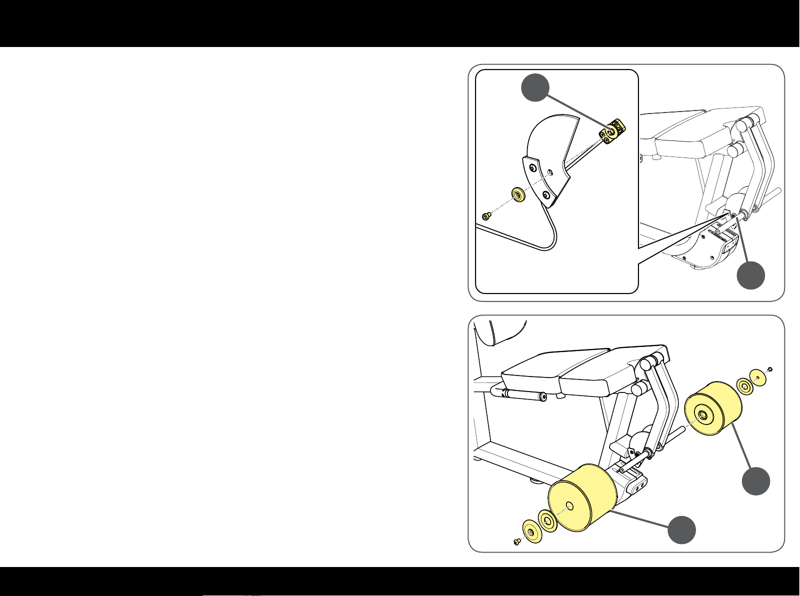
Unscrew the screws and remove the rollers (A).
A
A
Remove the stop buer and the plate.
47PLURIMA
Page 48
Replacing the cable
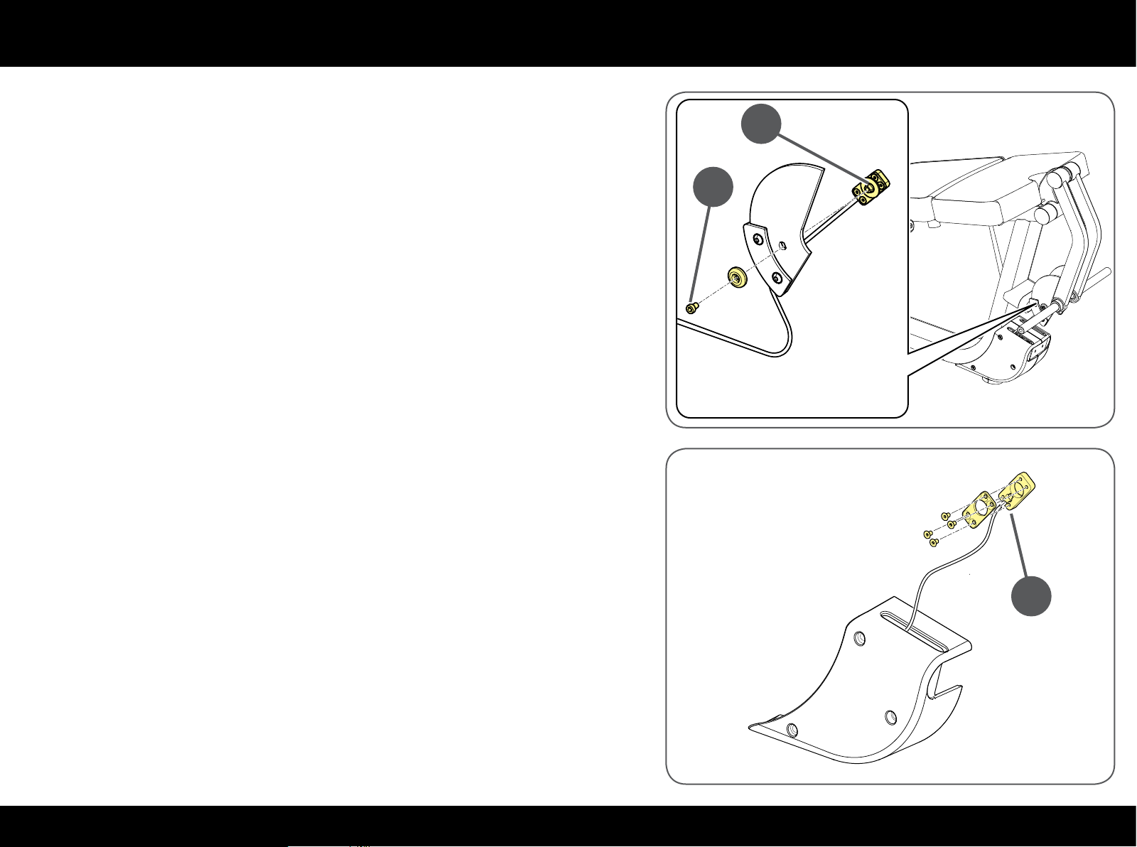
Unscrew the screw (C) to release the cable clamp (D) using a 4 mm T spanner;
remove the cable clamp (D).
Open the cable clamp (D) with a Phillips screwdriver.
Remove the cable from the clamp.
D
C
D
48PLURIMA
Page 49
Replacing the cable
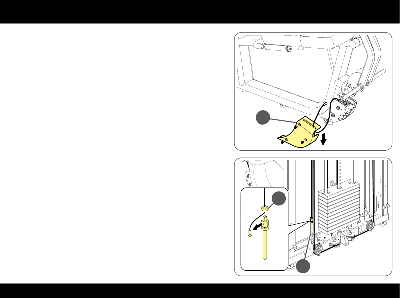
Remove the guard (E) with a 4 mm T spanner and slip the cable out of the slot.
Attach the new cable to the old cable.
E
Unscrew the adjustment screw (F).
Unscrew the nut (G) and take the cable out.
Take the nut (E) o the cable.
G
F
49PLURIMA
Page 50
Replacing the cable
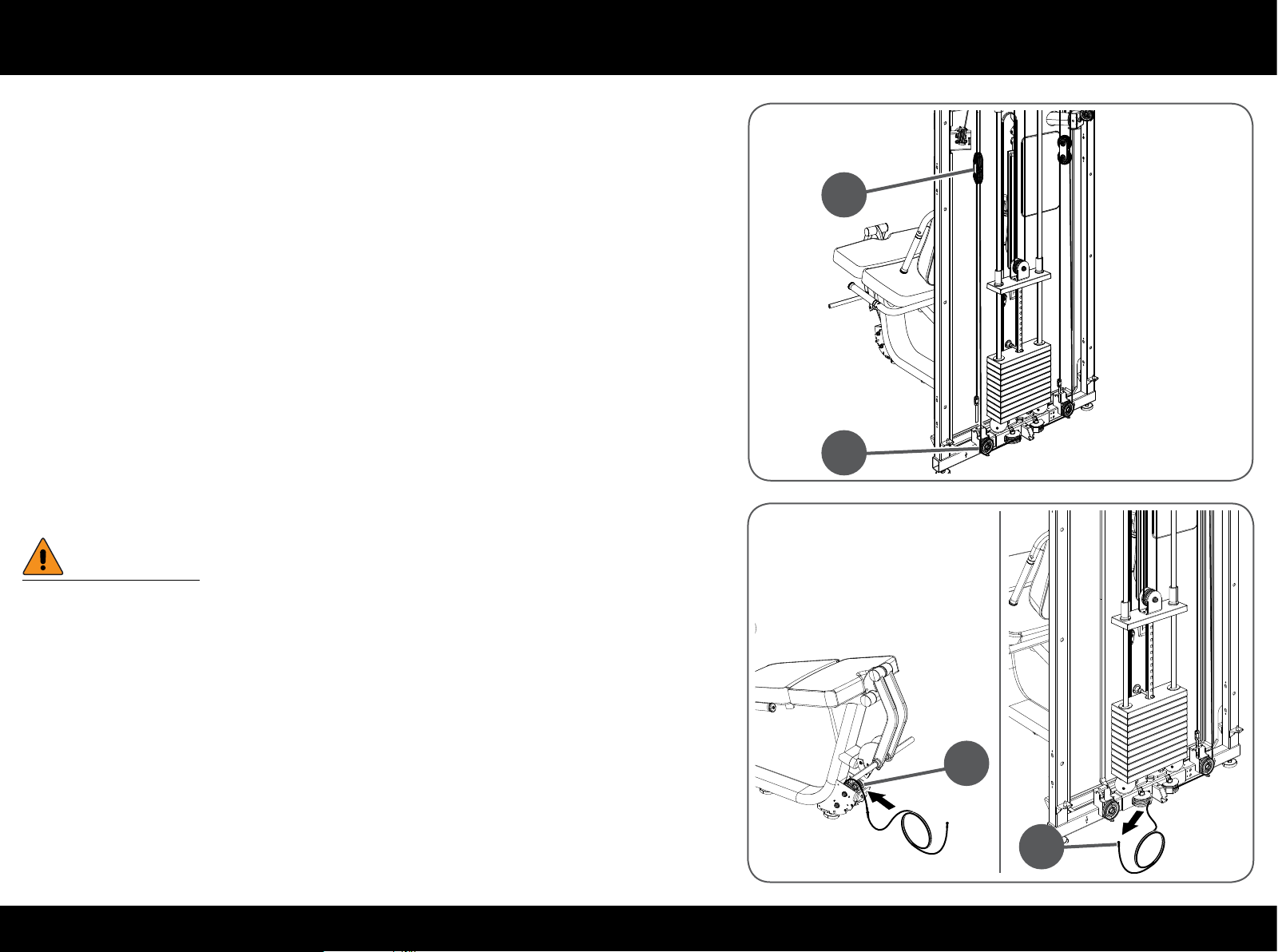
Take the cable out of the pulley group (H) and from the pulley (I).
H
I
Pull the old cable (J) to replace it with the new one.
W
Make sure you insert the cable joint correctly while threading it through
the pulley group (K).
K
J
50PLURIMA
Page 51
Replacing the cable
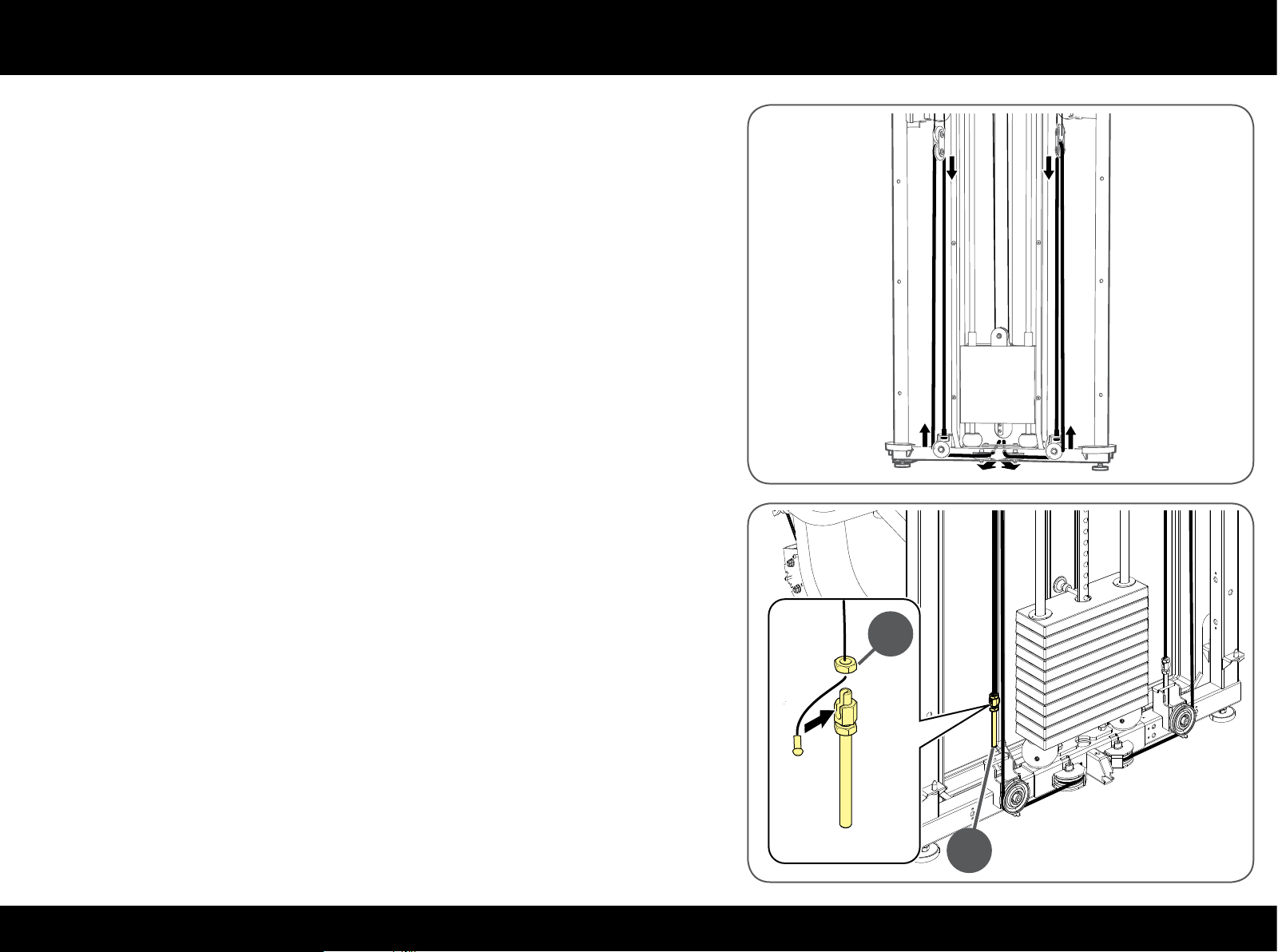
Follow the steps indicated in the drawing to insert the lever cables.
Check that the cable is laid correctly in the grooves of all the pulleys.
Insert the nut (G) in the cable.
Insert the cable in the adjustment screw housing (F) and then tighten the
nut (G).
Tighten the adjustment screw (F) in the frame.
G
F
51PLURIMA
Page 52
Replacing the cable
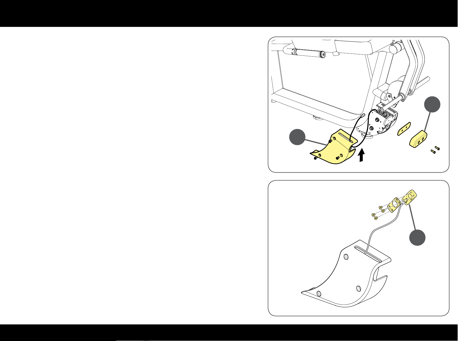
Insert the cable in the slot on the cover (E).
Tighten the cover (E) with a 4 mm T spanner.
Tighten the plate and stop buer (B).
B
E
Insert the cable in the clamp (D) and tighten with a Phillips screwdriver.
D
52PLURIMA
Page 53
Replacing the cable
Secure the cable clamp (D) on the lever (L) with a 4 mm T spanner.
D
L
Remount the 2 rollers (A).
Before remounting the guards and closing access to the inside parts, adjust
cable tension as described in the "Adjusting cable tension" paragraph.
A
A
53PLURIMA
Page 54
Replacing the cable
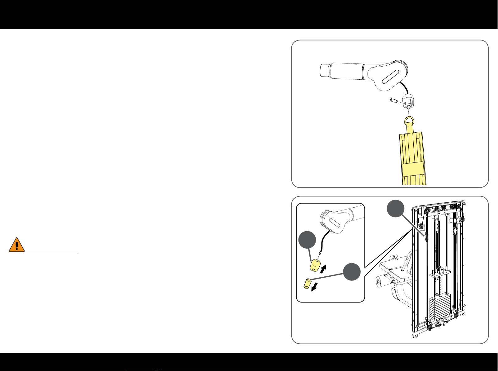
Replacing the cable of the arms
There is only one cable for the two arms.
Remove the 2 straps: unscrew the pin with a 5 mm T spanner.
Lift the bumper (M) in both arms and remove the bush (N).
Pull the bumper (M) out.
W
Hold the pulley groups (H) as they could fall to the ground when the
cable is loosened.
H
M
N
54PLURIMA
Page 55
Replacing the cable
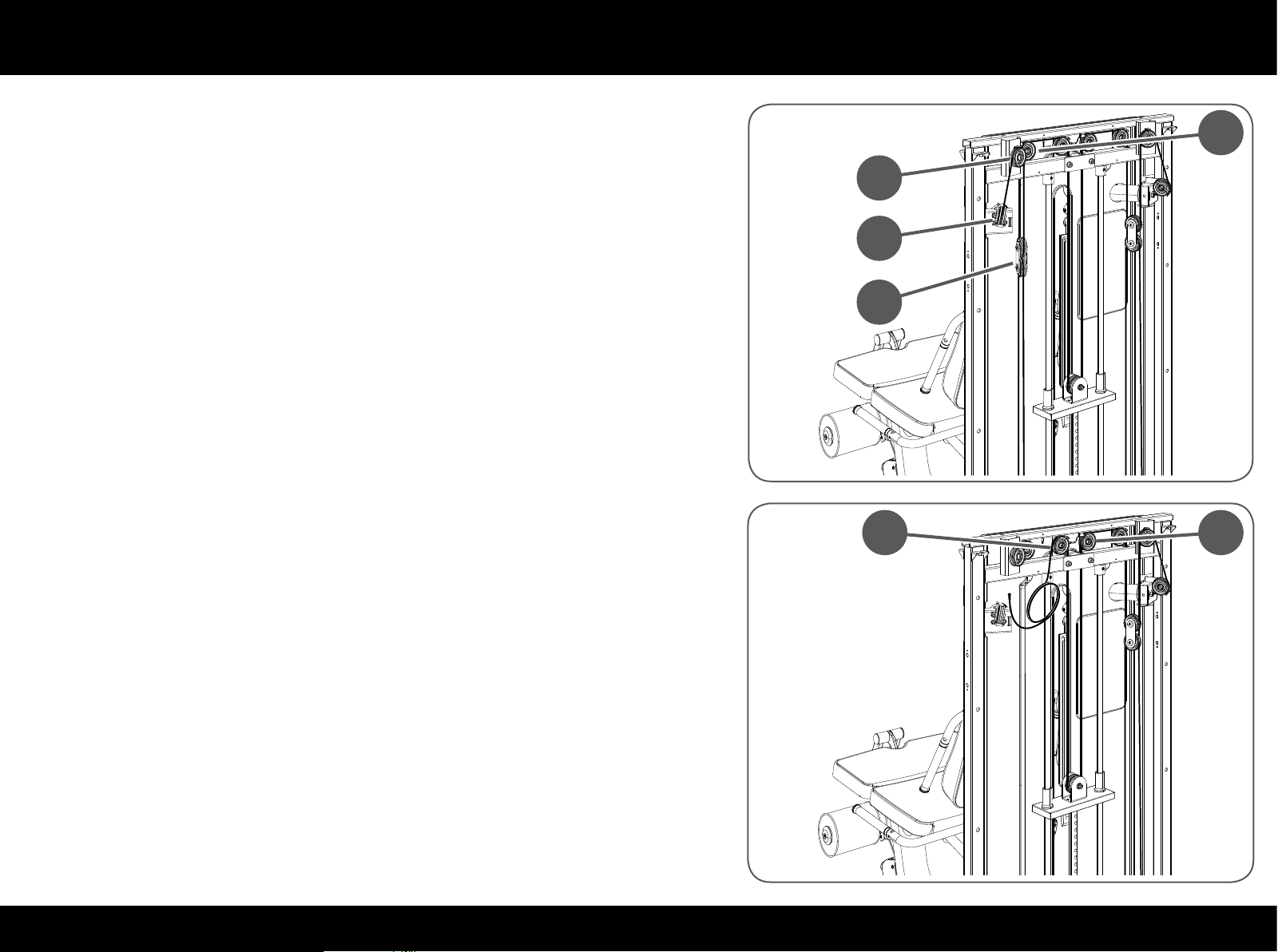
Take the cable out of the arm, then out of pulley (O) and then out of pulley (P).
Take the cable out of the pulley group (H); thread the cable through the frame
Q
hole, then through the pulley (Q).
Loosen the two central pulleys (R) with an 8 mm T spanner and a 17 mm openended spanner without removing them.
Loosen the pulley block on the crosspiece with a 17 mm adjustable spanner
and a 6 mm T spanner.
P
O
H
R R
Take the cable out of the 3 pulleys.
55PLURIMA
Page 56
Replacing the cable
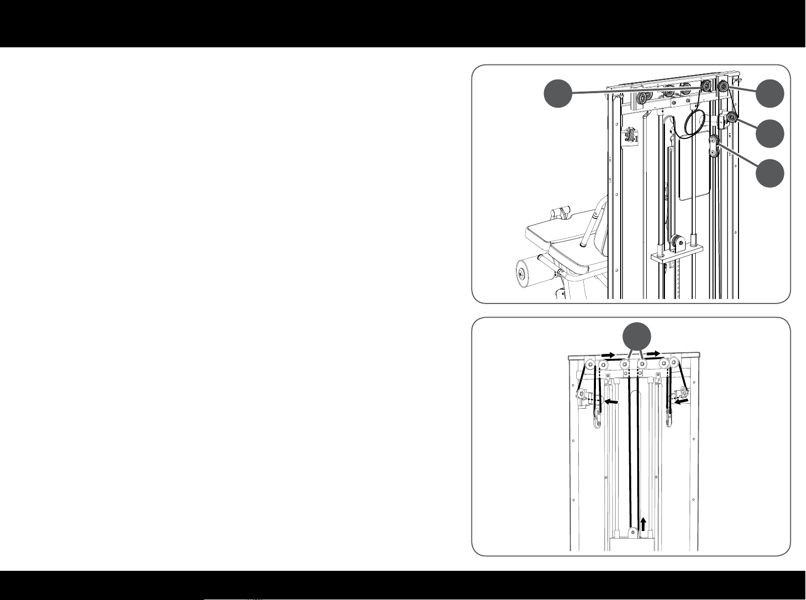
Take the cable out of the pulley (S) and then from the pulley group (H).
Take the cable out of pulleys (T) and (U).
Take the cable out of the arm.
Repeat the steps indicated in the drawing to insert the arm cable.
Check that the cable is laid correctly in the grooves of all the pulleys.
Retighten the central pulleys (R) and the crosspiece pulley.
S T
U
H
R
56PLURIMA
Page 57
Replacing the cable
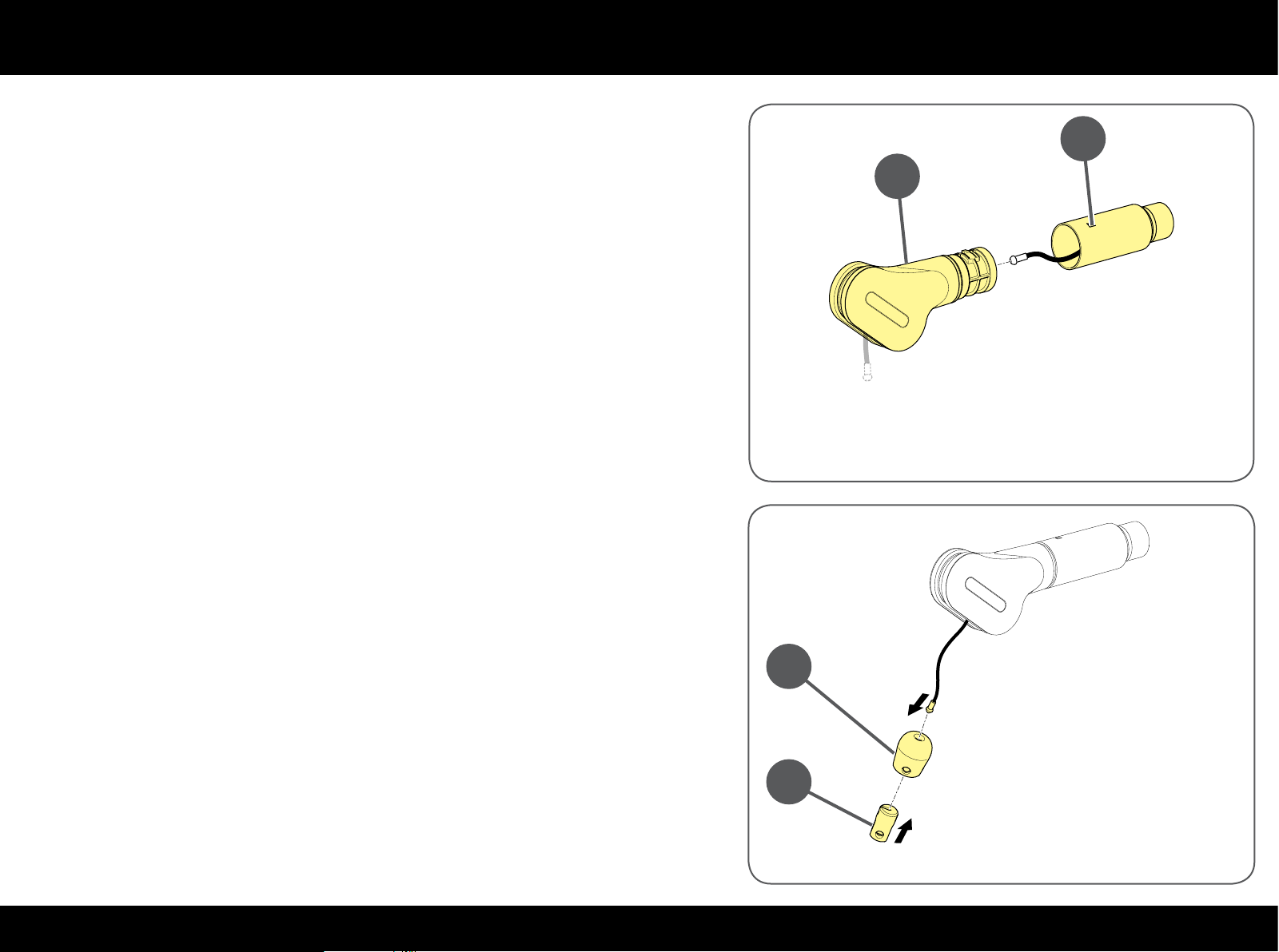
Press against the hole (V) to release the pivoting element (W).
Insert the cable in the arm and then in the pivoting element.
Insert the pivoting element (W) once again making sure it clicks in perfectly.
Insert the end of the cable in the bumper (M) and then in the bush (N).
Insert the open element (N) in the bumper (M).
V
W
M
N
57PLURIMA
Page 58
Replacing the cable
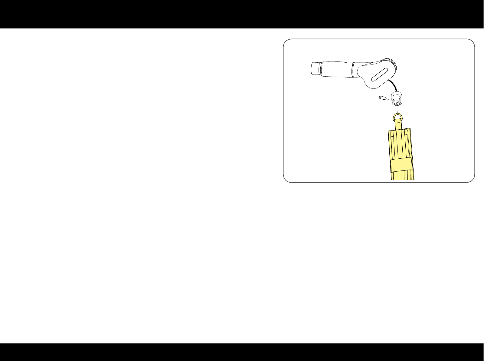
Mount the 2 straps: tighten the pin with a 5 mm T spanner.
58PLURIMA
Page 59
Replacing the cable
Press & Overhead Press
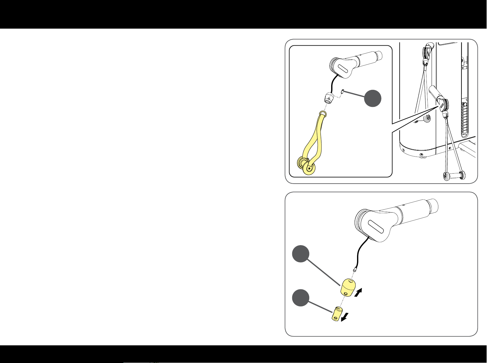
Each of the bottom arms has a cable. The cables of the two bottom arms are
replaced in the same way.
There is only one cable for the two top arms.
Remove the 2 bottom handles: unscrew the pin (A) with a 5 mm T spanner.
Lift the bumper (B) in both arms and remove the bush (C).
Pull the bumper (B) out.
A
B
C
59PLURIMA
Page 60
Replacing the cable
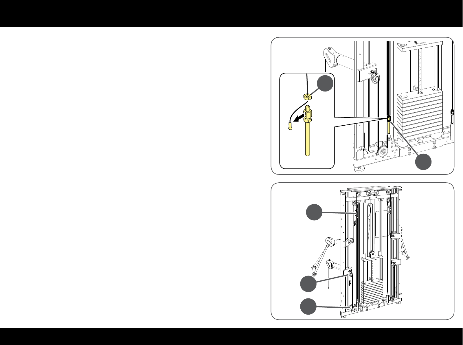
Unscrew the adjustment screw (D).
Unscrew the nut (E) and take the cable out.
Take the nut (E) o the cable.
E
D
Take the cable out of the arm and then from the pulley (F).
Take the cable out of pulleys (G) and then (H).
H
F
G
60PLURIMA
Page 61
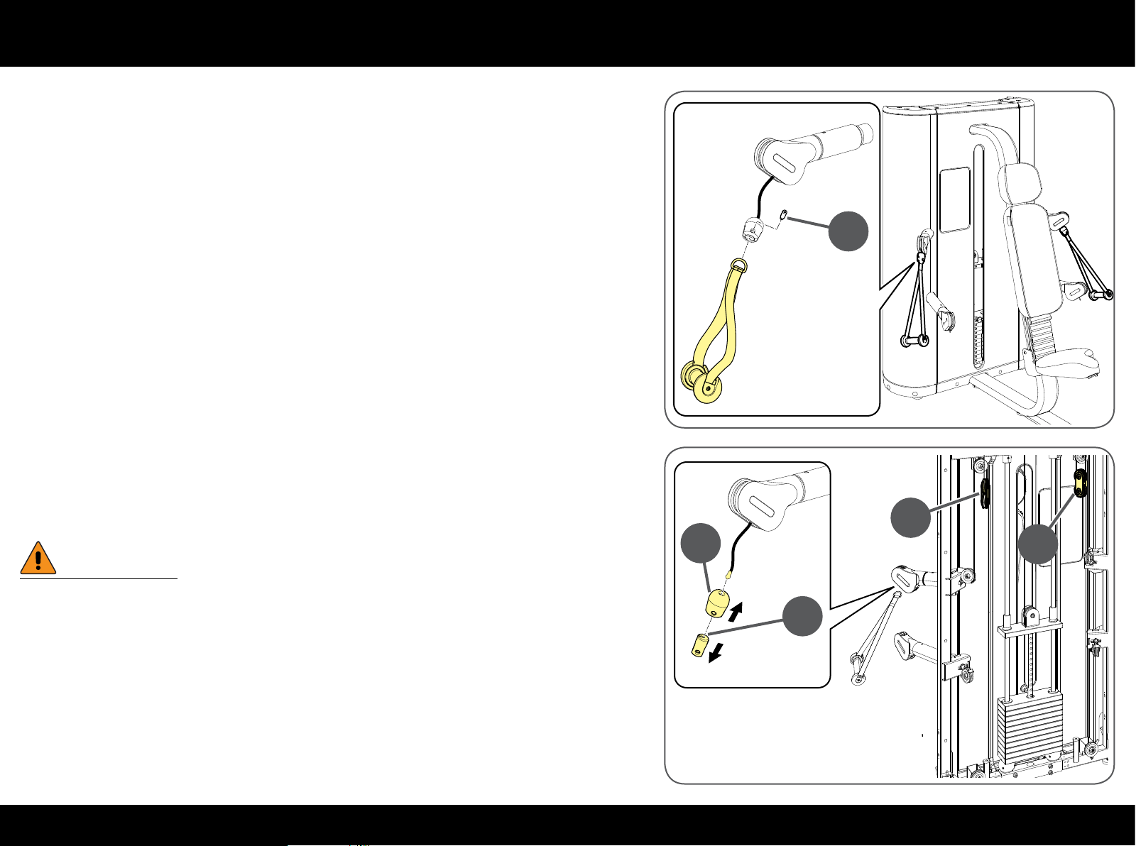
Replacing the cable
Remove the 2 top handles: unscrew the pin (I) with a 5 mm T spanner.
I
Lift the bumper (B) in both arms and remove the bush (C).
Pull the bumper (B) out.
W
Hold the pulley groups (H) as they could fall to the ground when the
cable is loosened.
B
H
H
C
61PLURIMA
Page 62
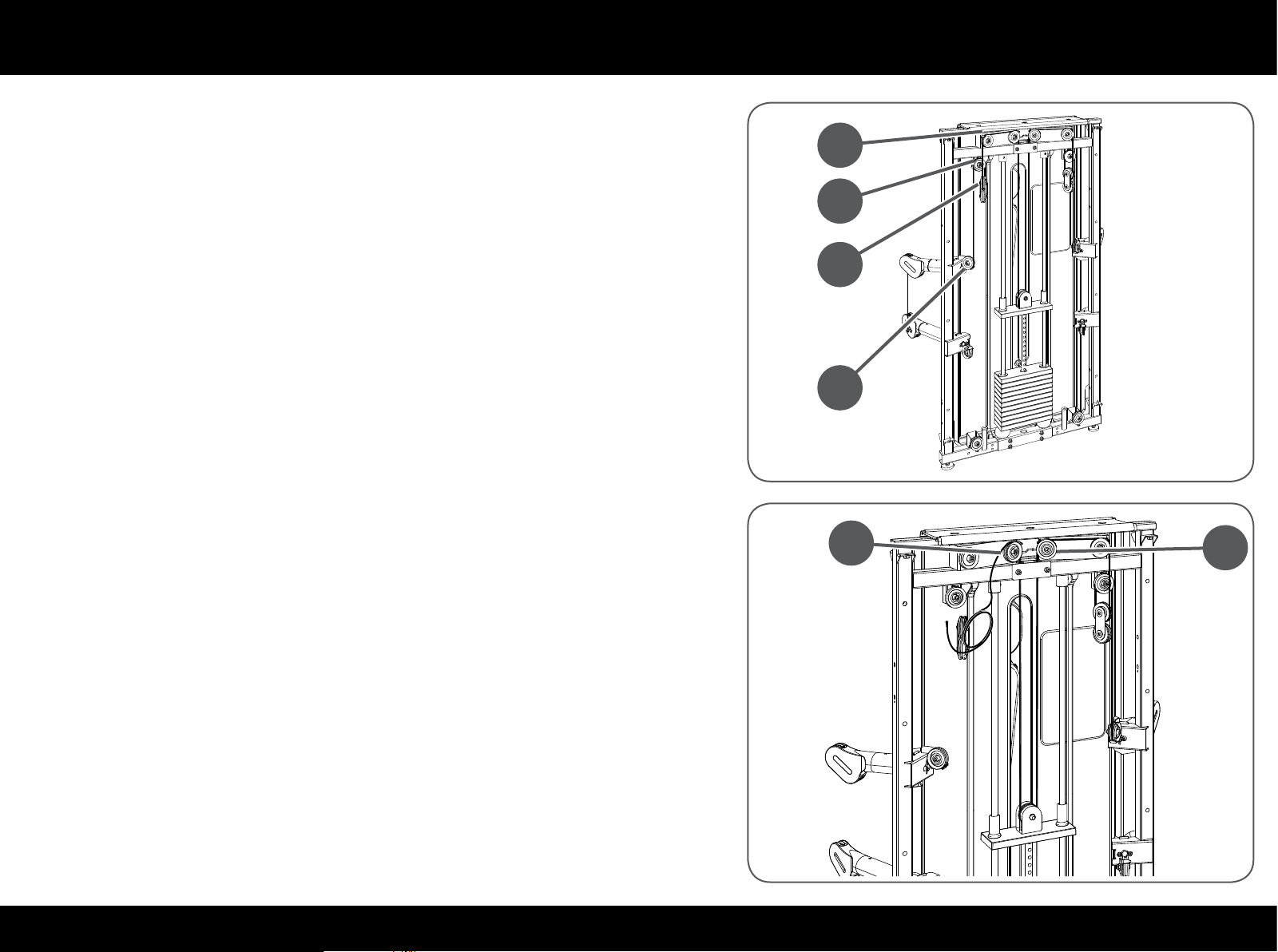
Replacing the cable
Take the cable out of the arm, then out of pulley (J) and then out of pulley (K).
Take the cable out of the pulley group (H) and then from the pulley (L).
Loosen the two central pulleys (M) with an 8 mm T spanner and a 17 mm openended spanner without removing them.
Loosen the pulley block on the crosspiece with a 17 mm adjustable spanner
and a 6 mm T spanner.
L
K
H
J
M
M
Take the cable out of the 3 pulleys.
62PLURIMA
Page 63
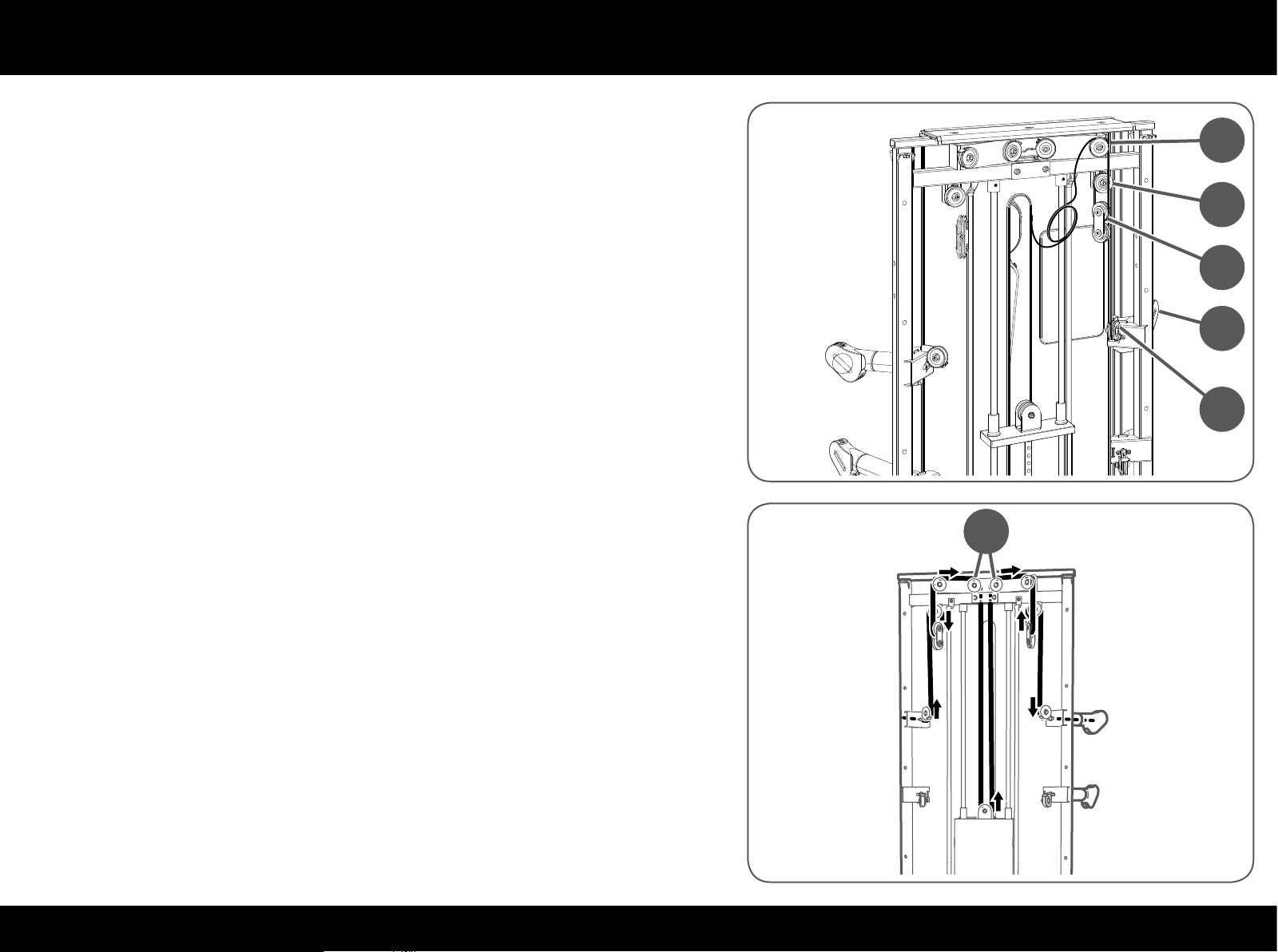
Replacing the cable
Take the cable out of the next pulleys (N), (H), (O) e (P).
Take the cable out of the arm (Q).
Repeat the steps indicated in the drawing to insert the top cable.
Check that the cable is laid correctly in the grooves of all the pulleys.
Retighten the central pulleys (M) and the crosspiece pulley.
N
O
H
Q
P
M
63PLURIMA
Page 64
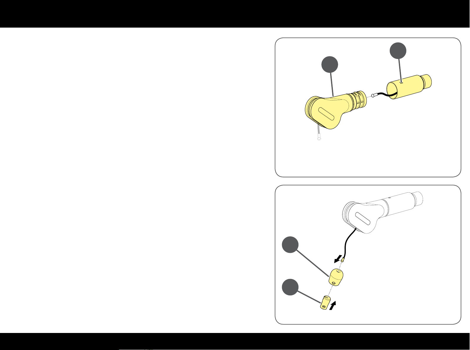
Replacing the cable
Press against the hole (R) to release the pivoting element (S).
Insert the cable in the arm and then in the pivoting element.
Insert the pivoting element (S) in its housing making sure it clicks in perfectly.
Insert the end of the cable in the bumper (B) and then in the bush (C).
Insert the open element (C) in the bumper (B).
R
S
B
C
64PLURIMA
Page 65
Replacing the cable
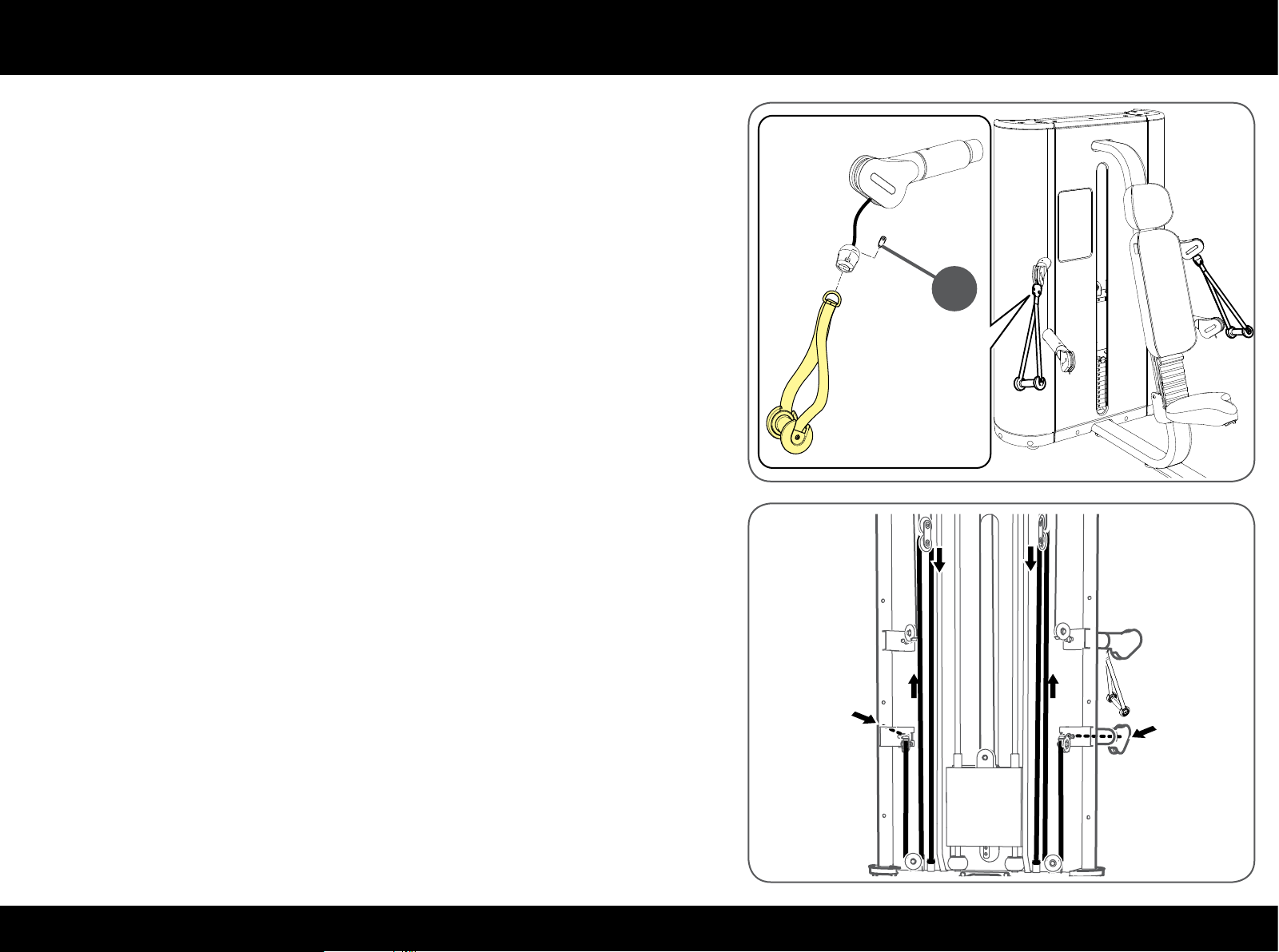
Insert the ring of the handle in the bush and lock it with the pin (I); secure the
pin with a 5 mm T spanner.
I
Repeat the steps indicated in the drawing to insert the bottom cable.
Check that the cable is laid correctly in the grooves of all the pulleys.
65PLURIMA
Page 66
Replacing the cable
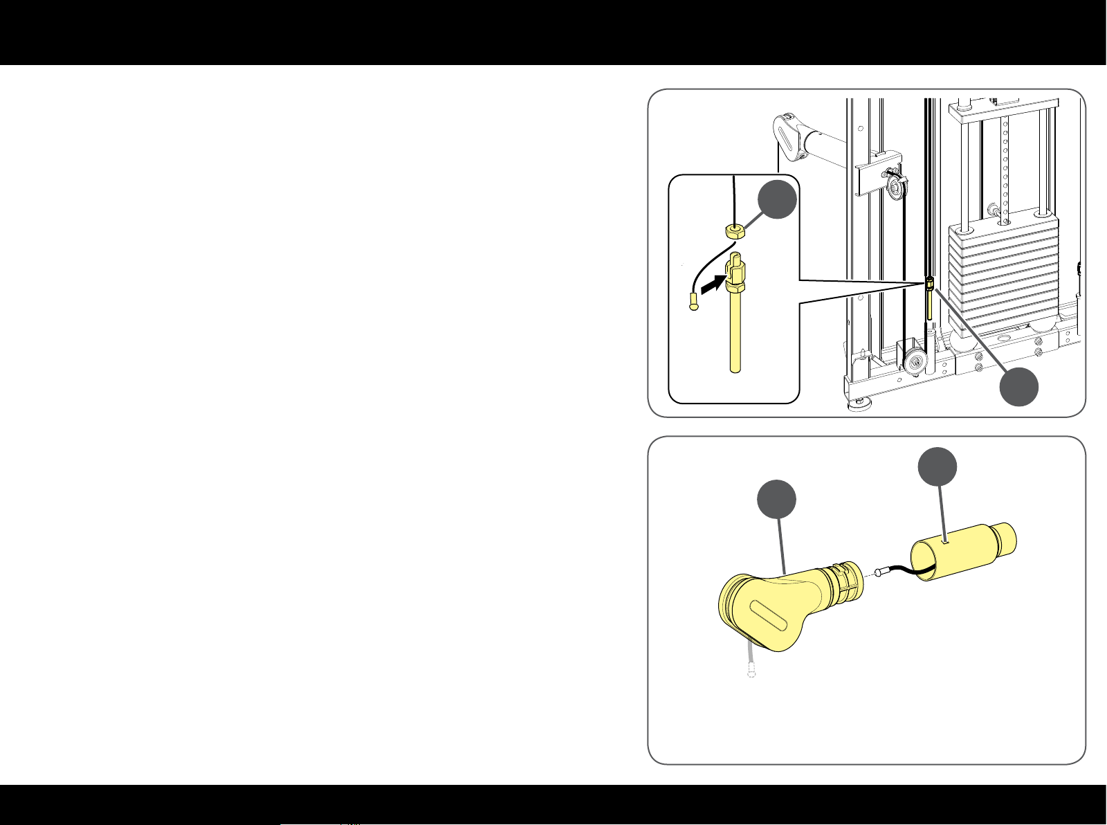
Insert the nut (E) in the cable.
Insert the cable in the adjustment screw housing (D) and then tighten the
nut (E).
Tighten the adjustment screw (D) in place.
Press against the hole (T) to release the pivoting element (U).
Insert the cable in the arm and then in the pivoting element.
Insert the pivoting element (U) in its housing making sure it clicks in perfectly.
E
D
T
U
66PLURIMA
Page 67
Replacing the cable
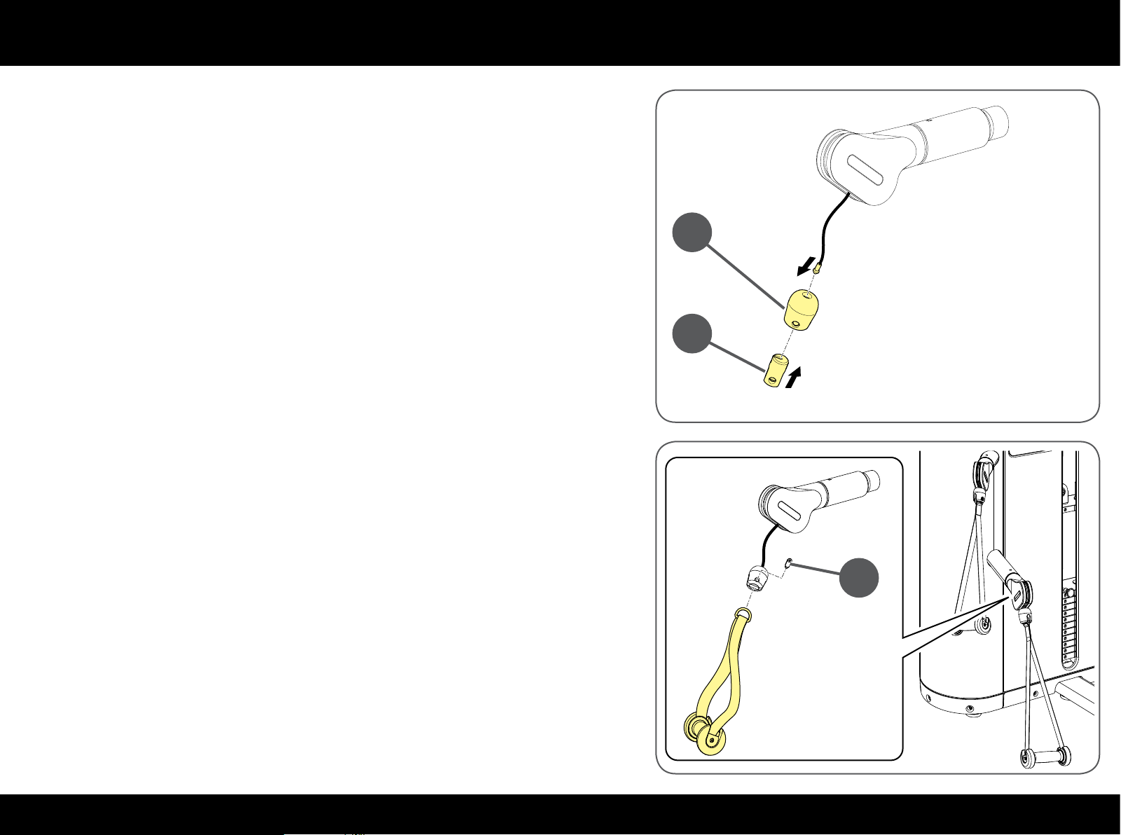
Insert the end of the cable in the bumper (B) and then in the bush (C).
Insert the open element (C) in the bumper (B).
B
C
Insert the ring of the handle in the bush and lock it with the pin (C); secure the
pin with a 5 mm T spanner.
Before remounting the guards and closing access to the inside parts, adjust
cable tension as described in the "Adjusting cable tension" paragraph. Replacing
the cable.
C
67PLURIMA
Page 68
Replacing the cable
High & Low Pull
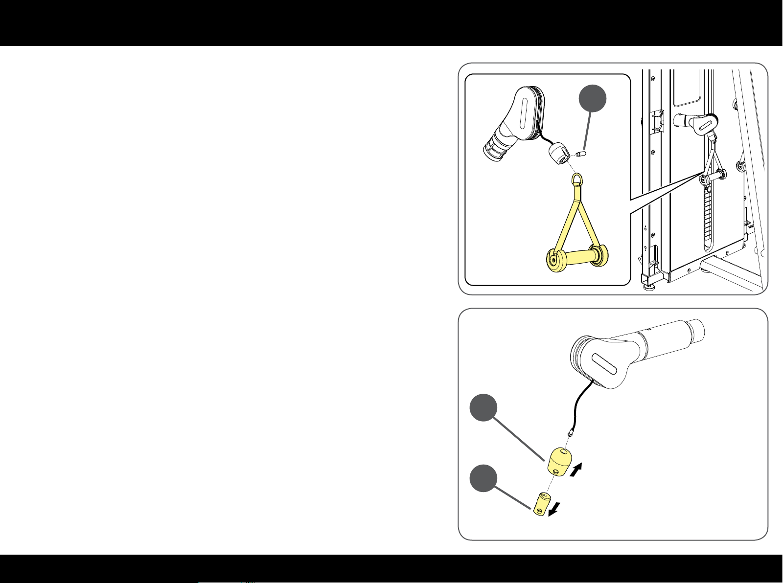
Each of the bottom arms has a cable. The cables of the two bottom arms are
replaced in the same way.
There is only one cable for the two top arms.
Remove the 2 bottom handles: unscrew the pin (A) with a 5 mm T spanner.
A
Lift the bumper (B) in both arms and remove the bush (C).
Pull the bumper (B) out.
B
C
68PLURIMA
Page 69
Replacing the cable
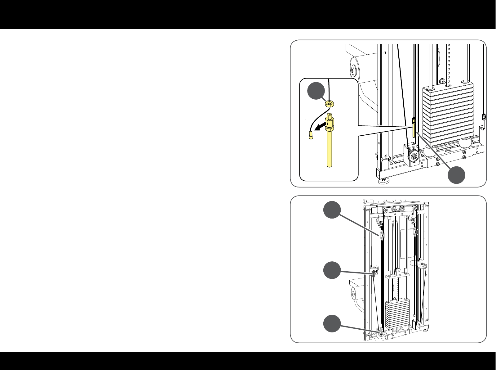
Unscrew the adjustment screw (D).
Unscrew the nut (E) and take the cable out.
Take the nut (E) o the cable.
E
D
Take the cable out of the arm and then from the pulley (F).
Take the cable out of the pulley (G) and then out of the pulley group (H).
H
F
G
69PLURIMA
Page 70
Replacing the cable
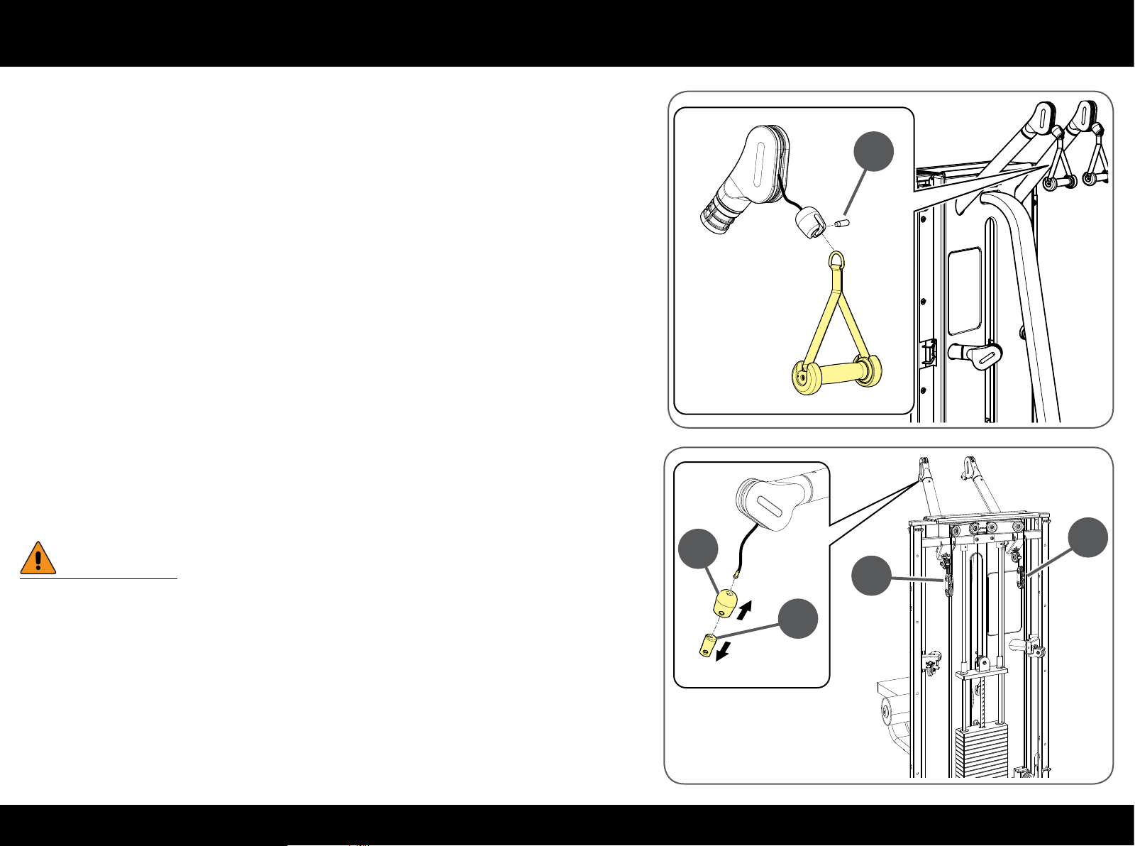
Remove the 2 top handles: unscrew the pin (I) with a 5 mm T spanner.
I
Lift the bumper (B) in both arms and remove the bush (C).
Pull the bumper (B) out.
W
Hold the pulley groups (H) as they could fall to the ground when the
cable is loosened.
B
H
H
C
70PLURIMA
Page 71
Replacing the cable
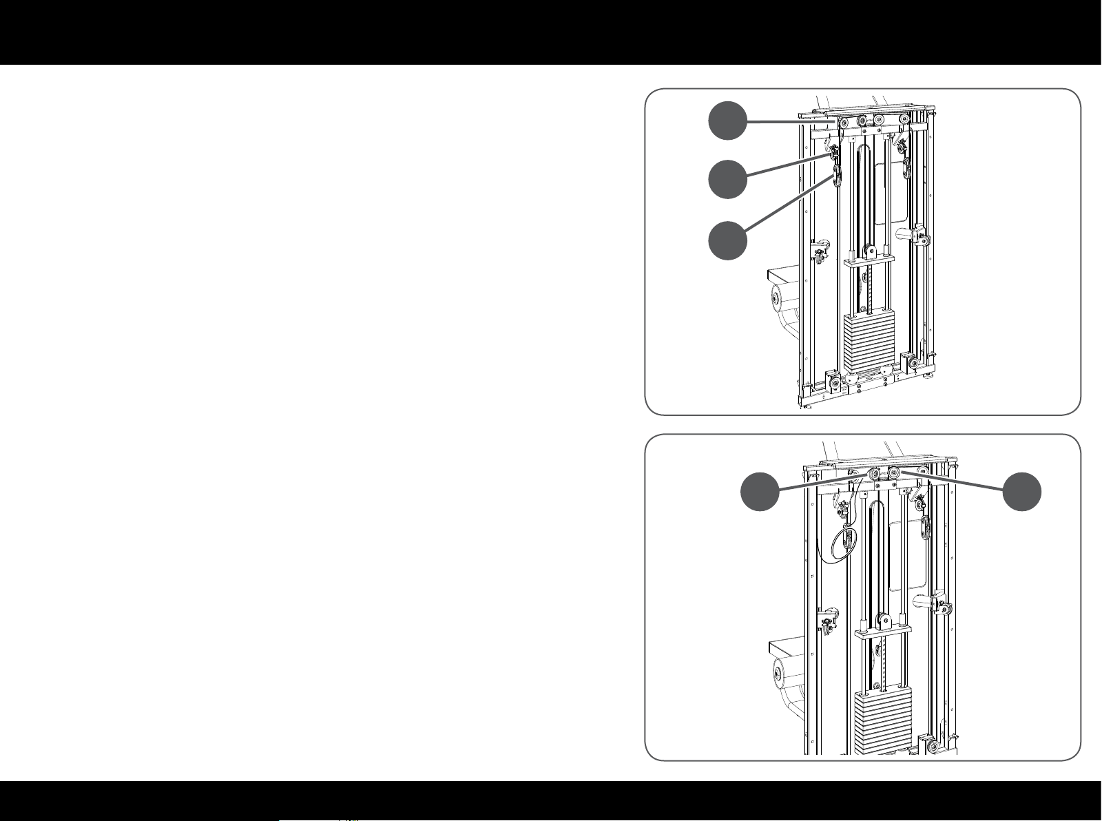
Take the cable out of the arm and then from the pulley (J).
Take the cable out of the pulley group (H) and then from the pulley (K).
Loosen the two central pulleys (L) with an 8 mm T spanner and a 17 mm openended spanner without removing them.
Loosen the pulley block on the crosspiece with a 17 mm adjustable spanner
K
J
H
L L
and a 6 mm T spanner.
Take the cable out of the 3 pulleys.
71PLURIMA
Page 72
Replacing the cable
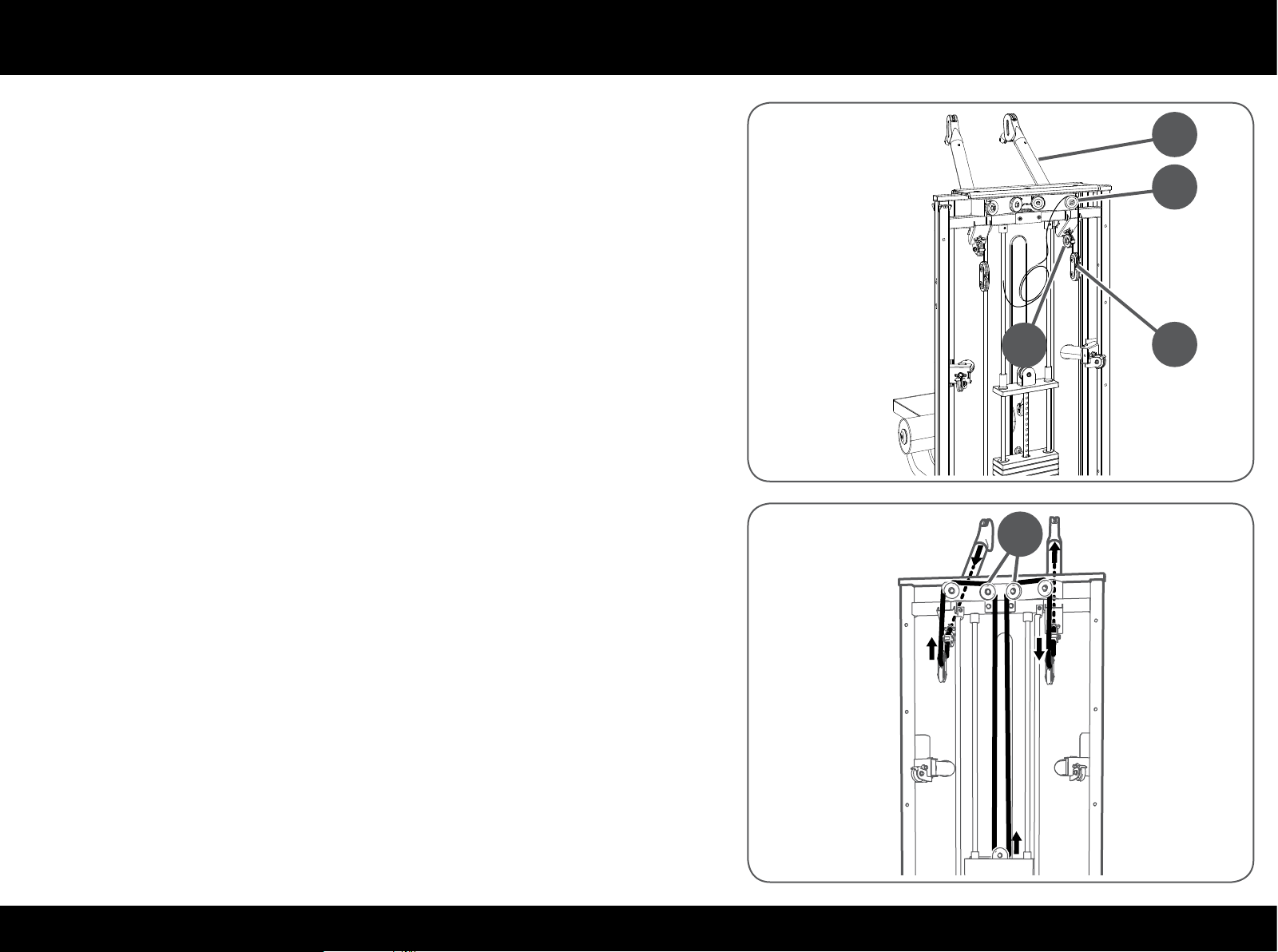
Take the cable out of the next pulleys (M), (H) and (N).
Take the cable out of the arm (O).
Repeat the steps indicated in the drawing to insert the top cable.
Check that the cable is laid correctly in the grooves of all the pulleys.
Retighten the central pulleys (L) and the crosspiece pulley.
L
N
O
M
H
72PLURIMA
Page 73
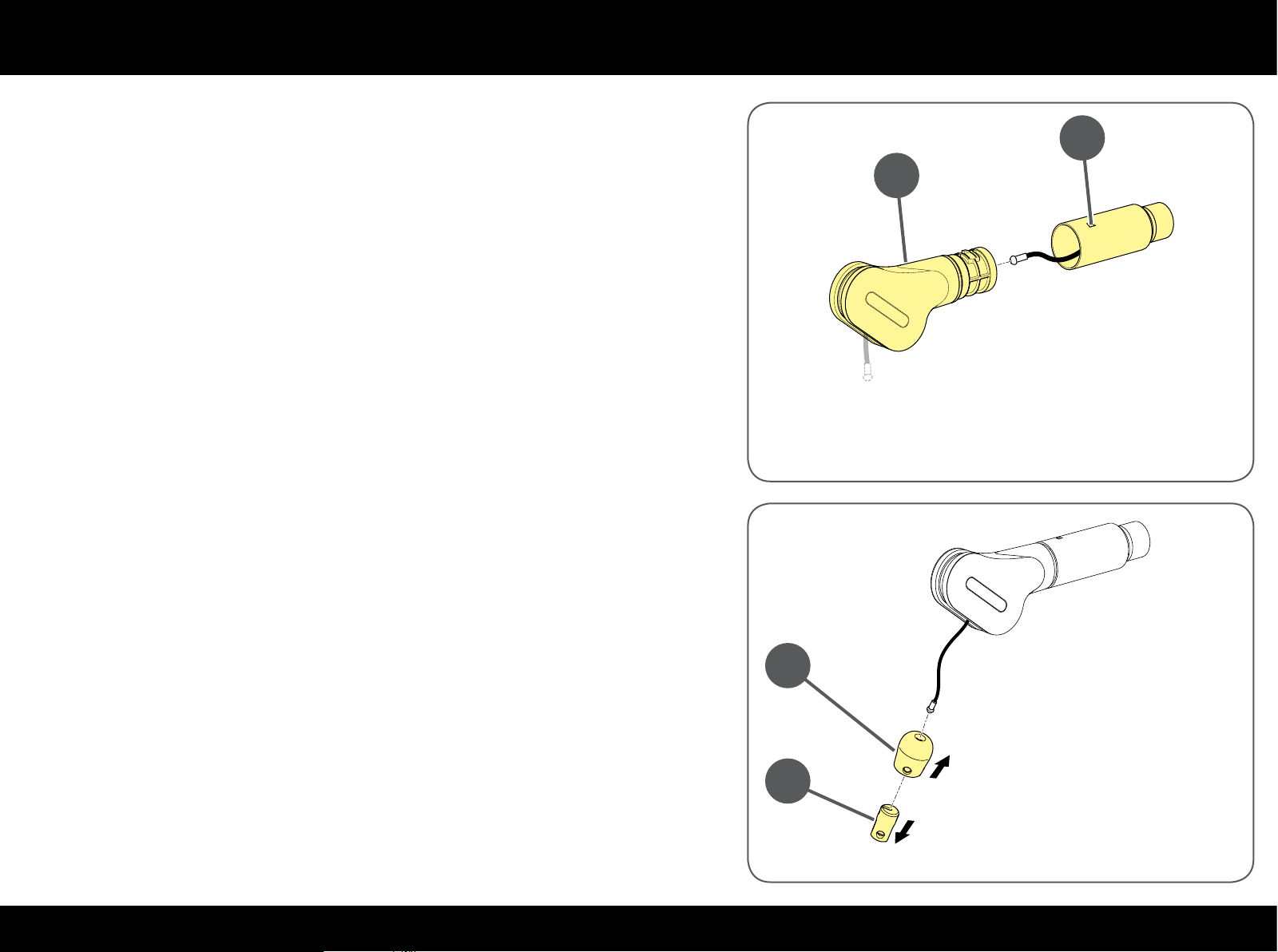
Replacing the cable
Press against the hole (P) to release the pivoting element (Q).
Insert the cable in the arm and then in the pivoting element.
Insert the pivoting element (Q) once again making sure it clicks in perfectly.
Insert the end of the cable in the bumper (B) and then in the bush (C).
Insert the open element (C) in the bumper (B).
P
Q
B
C
73PLURIMA
Page 74
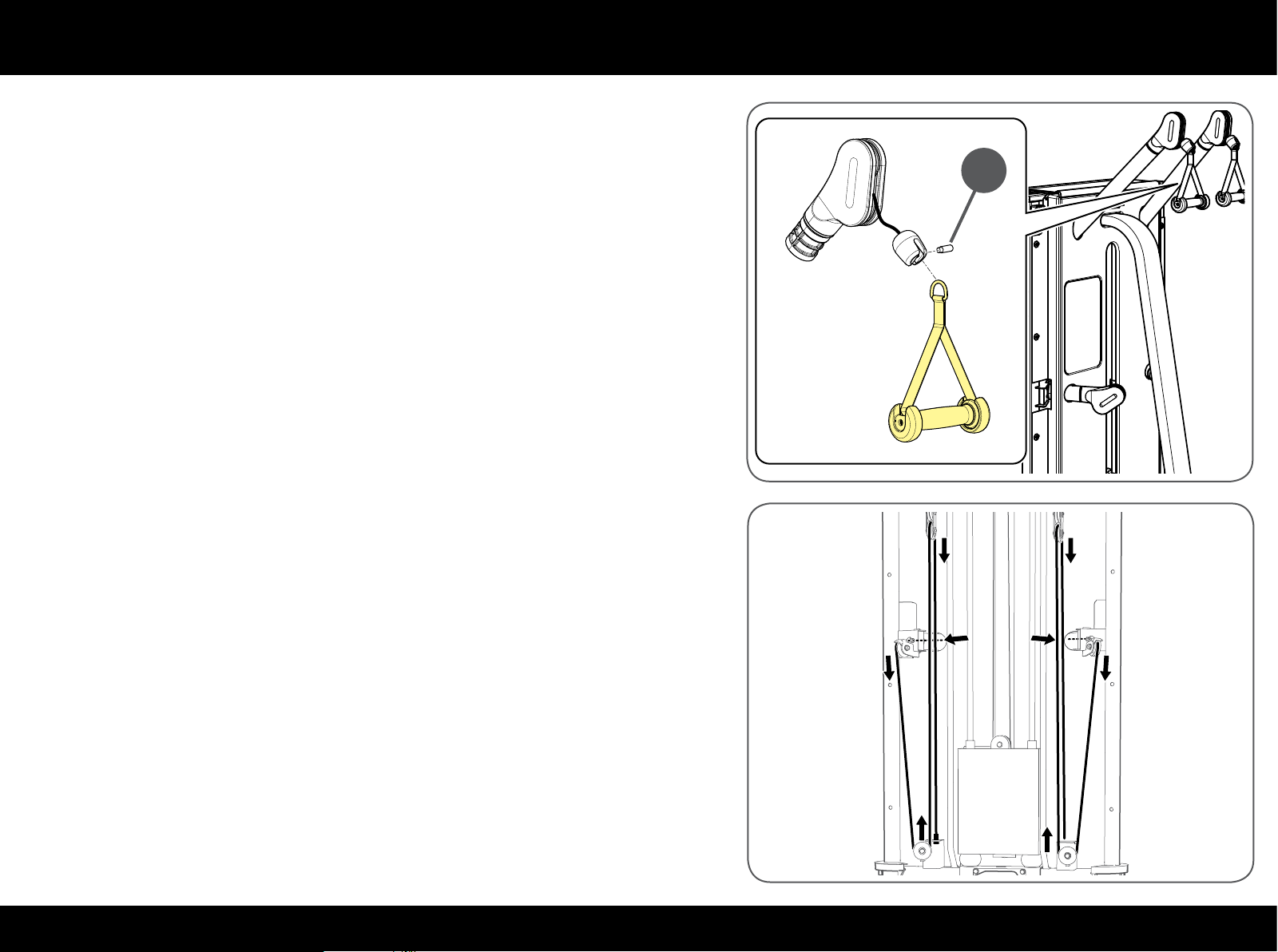
Replacing the cable
Insert the ring of the handle in the bush and lock it with the pin (I); secure the
pin with a 5 mm T spanner.
I
Repeat the steps indicated in the drawing to insert the bottom cable.
Check that the cable is laid correctly in the grooves of all the pulleys.
74PLURIMA
Page 75
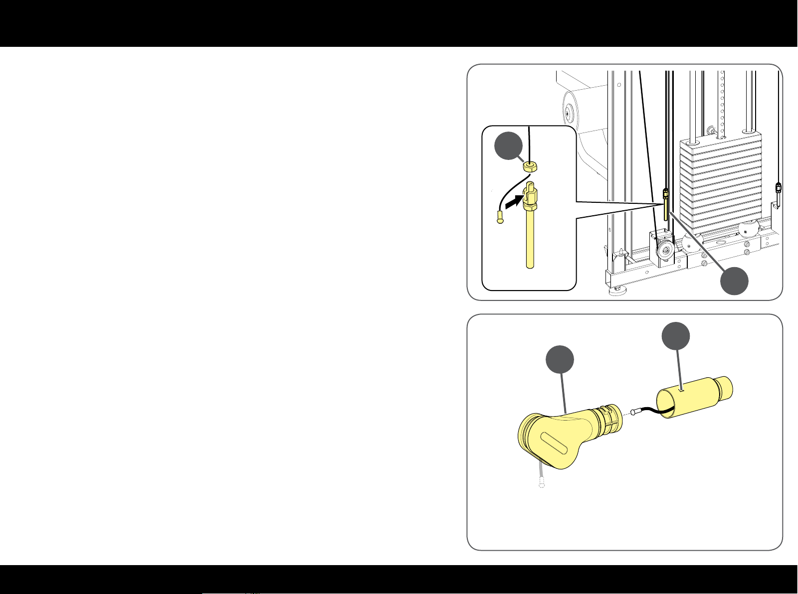
Replacing the cable
Insert the nut (E) in the cable.
Insert the cable in the adjustment screw housing (D) and then tighten the
nut (E).
Tighten the adjustment screw (D) in place.
Press against the hole (P) to release the pivoting element (Q).
Insert the cable in the arm and then in the pivoting element.
Insert the pivoting element (Q) once again making sure it clicks in perfectly.
E
D
P
Q
75PLURIMA
Page 76
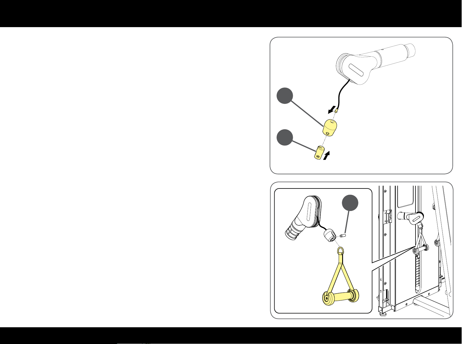
Replacing the cable
Insert the end of the cable in the bumper (B) and then in the bush (C).
Insert the open element (C) in the bumper (B).
B
C
Insert the ring of the handle in the bush and lock it with the pin (A); secure the
pin with a 5 mm T spanner.
Before remounting the guards and closing access to the inside parts, adjust
cable tension as described in the "Adjusting cable tension" paragraph.
A
76PLURIMA
Page 77
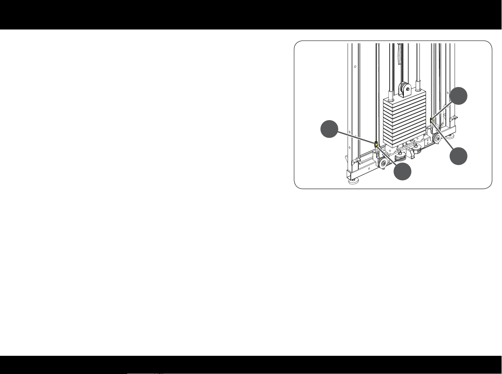
Adjusting cable tension
Before continuing, remove the guards to reach the whole cable assembly as
described in the "Reaching the internal parts" paragraph.
To adjust the tension of the two bottom cables, loosen the lock nut (A) and
then either tighten or loosen the screw (B); once done, retighten the nut with a
19mm adjustable spanner.
B
B
A
A
77PLURIMA
Page 78
Technical Support Service
The Technogym Technical Support Service provides:
- telephone assistance;
- information on which service calls are covered and not covered by warranty;
- on-site assistance;
Technogym Technical
Support Service
- delivery of original replacement parts
When contacting the Technogym Technical Support Service, please specify the following details:
- equipment model,
- date of purchase,
- serial number,
- precise description of the problem.
W
Any operations carried out by persons not authorized by Technogym on the equipment will invalidate the warranty.
tel: 0547 650650
fax: 0547 650150
email: [email protected]
78PLURIMA
Page 79
Storage
If the equipment is not expected to be used for a prolonged period, we recommend storing it:
- in a clean and dry place, covered with a cloth to protect it from dust;
- in an environment with a temperature between +10°C and +25°C and humidity between 20% and 90%.
Disposal
It is always good practise to ensure that the equipment can never constitute a hazard; therefore do not leave the equipment where children
may play with it.
Do not dump the equipment in the environment, or in public areas or private areas accessible to the public.
The equipment is made from recyclable materials such as steel, aluminium and plastic, which must be disposed of in the manner prescribed
by the urban refuse collection regulations in force, by rms specialised in urban and environmental hygiene.
79PLURIMA
 Loading...