


USER MANUAL
DIGITAL TERRESTRIAL RECEIVER
ECO 2STBA08

1
CONTENTS
1. INTRODUCTION.................................................................................................................................2
IN THE BOX............................................................................................................................................2
POWER CORD (MAINS LEAD)..............................................................................................................3
2. SAFETY PRECAUTIONS...................................................................................................................4
YOUR DIGITAL RECEIVER...................................................................................................................5
3. PREPARING.......................................................................................................................................5
3.1. REMOTE CONTROL.......................................................................................................................5
3.2. CONNECTIONS...............................................................................................................................6
3.2.1. CONNECTION TO THE TV..........................................................................................................6
3.2.2. CONNECTION TO A VCR...........................................................................................................6
3.2.3. AERIAL CONNECTION................................................................................................................7
3.2.4. PUTTING INTO OPERATION......................................................................................................7
3.2.5. SOCKETS.....................................................................................................................................7
4. REMOTE CONTROL FUNCTIONS....................................................................................................8
4.1. REMOTE CONTROL LAYOUT........................................................................................................8
5. MENU INTERFACE..........................................................................................................................10
FIRST TIME INSTALLATION................................................................................................................10
5.1. MAIN MENU...................................................................................................................................10
5.1.1. CHANNEL LIST..........................................................................................................................10
5.1.1.1. NAVIGATING THE WHOLE LIST OF CHANNELS.................................................................11
5.1.1.2. DELETING UNWANTED CHANNEL.......................................................................................11
5.1.1.3. RENAMING CHANNELS.........................................................................................................11
5.1.1.4. ADDING LOCKS TO CHANNELS...........................................................................................11
5.1.1.5. SETTING FAVOURITES.........................................................................................................11
5.2. INSTALLATION..............................................................................................................................12
5.2.1. ADD NEW CHANNELS..............................................................................................................12
5.2.1.1. AUTOMATIC SEARCH............................................................................................................12
5.2.1.2. MANUAL SEARCH..................................................................................................................12
5.2.2. FIRST TIME INSTALLATION.....................................................................................................13
5.3. CONFIGURATION.........................................................................................................................13
5.3.1. AUDIO LANGUAGE....................................................................................................................13
5.3.2. SUBTITLE...................................................................................................................................13
5.3.3. TV TYPE.....................................................................................................................................13
5.3.4. TV OUT.......................................................................................................................................13
5.3.5. FAVOURITE MODE....................................................................................................................14
5.3.6. EPG PREFERENCE...................................................................................................................14
5.3.7. SCAN ENCRYPTED CHANNELS..............................................................................................14
5.3.8. RECEIVER UPGRADE...............................................................................................................14
5.3.9. PARENTAL SETTINGS..............................................................................................................15
5.3.9.i. Menu Lock.................................................................................................................................15
5.3.9.ii. Set Lock Key............................................................................................................................15
5.4. TIMERS MENU..............................................................................................................................15
5.5. LANGUAGE...................................................................................................................................16
6. ADVANCED OPERATION................................................................................................................16
6.1. ELECTRONIC PROGRAMME GUIDE (7 DAYS EPG).................................................................16
6.2. MESSAGES...................................................................................................................................17
6.3. CHANNEL NAVIGATION...............................................................................................................17
6.3. CHANNEL NAVIGATION...............................................................................................................18
6.4. VOLUME CONTROL.....................................................................................................................18
6.5. DIGITAL TELETEXT......................................................................................................................19
6.6. WIDESCREEN...............................................................................................................................19
6.7. SUBTITLE......................................................................................................................................19
6.8. TV / DTV KEY................................................................................................................................19
7. TROUBLE SHOOTING GUIDE........................................................................................................20
8. SPECIFICATIONS............................................................................................................................21
9. IMPORTANT NOTICE......................................................................................................................22
DIGITAL SWITCHOVER AND YOUR TV EQUIPMENT......................................................................22

2
1. INTRODUCTION
Thank you for purchasing this product. It will give you good service if you take note of all safety notices and
recommendations.
IN THE BOX
Inside your receiver package you should have;
1 x This user guide
1 x Quick start guide
1 x Digital terrestrial television receiver
1 x Remote control
2 x 1,5 V R-03/AAA
1 x RF lead
3
POWER CORD (MAINS LEAD)
Do not place the product where a piece of furniture or other heavy object could trap the power cord (mains lead).
Handle the power cord by the plug. Do not pull out the plug by tugging the cord and never touch the power cord
when your hands are wet as this could cause a short circuit or electric shock. Never make a knot in the cord or tie it
with other cords. The power cords should be routed in such a way that they are not likely to be stepped on. A
damaged power cord can cause fire or give you an electrical shock. Check the power cord periodically to see if it is
damaged. If it is damaged, please ask an approved service agent to replace it.
For your own safety read following instructions carefully before attempting to connect this device to the mains.
This unit is designed to operate on a 220V-240V AC, 50-60 Hz supply only. Connecting it to other power sources
may damage it. Ensure that the supply corresponds to the information on the rating label on the bottom of the unit.
This component system may be fitted with a non-rewireable plug. If it is necessary to change the fuse in a nonrewireable plug, the fuse cover must be refitted. If the fuse cover becomes lost or damaged, the plug most not be
used until a replacement, available from the manufacturer, is obtained. It is important that the colour of the
replacement fuse cover corresponds with the colour marking on the base of the plug. If the plug needs to be
changed because it is not suitable for your socket, or it becomes damaged, it should be cut off and the fuse
removed immediately. Please dispose of the plug safely and out of reach from children. Under no circumstance
should the cut-off plug be inserted into a mains socket outlet due to high risk of electric shock. Then fit an
appropriate plug carefully following the wiring instructions shown below.
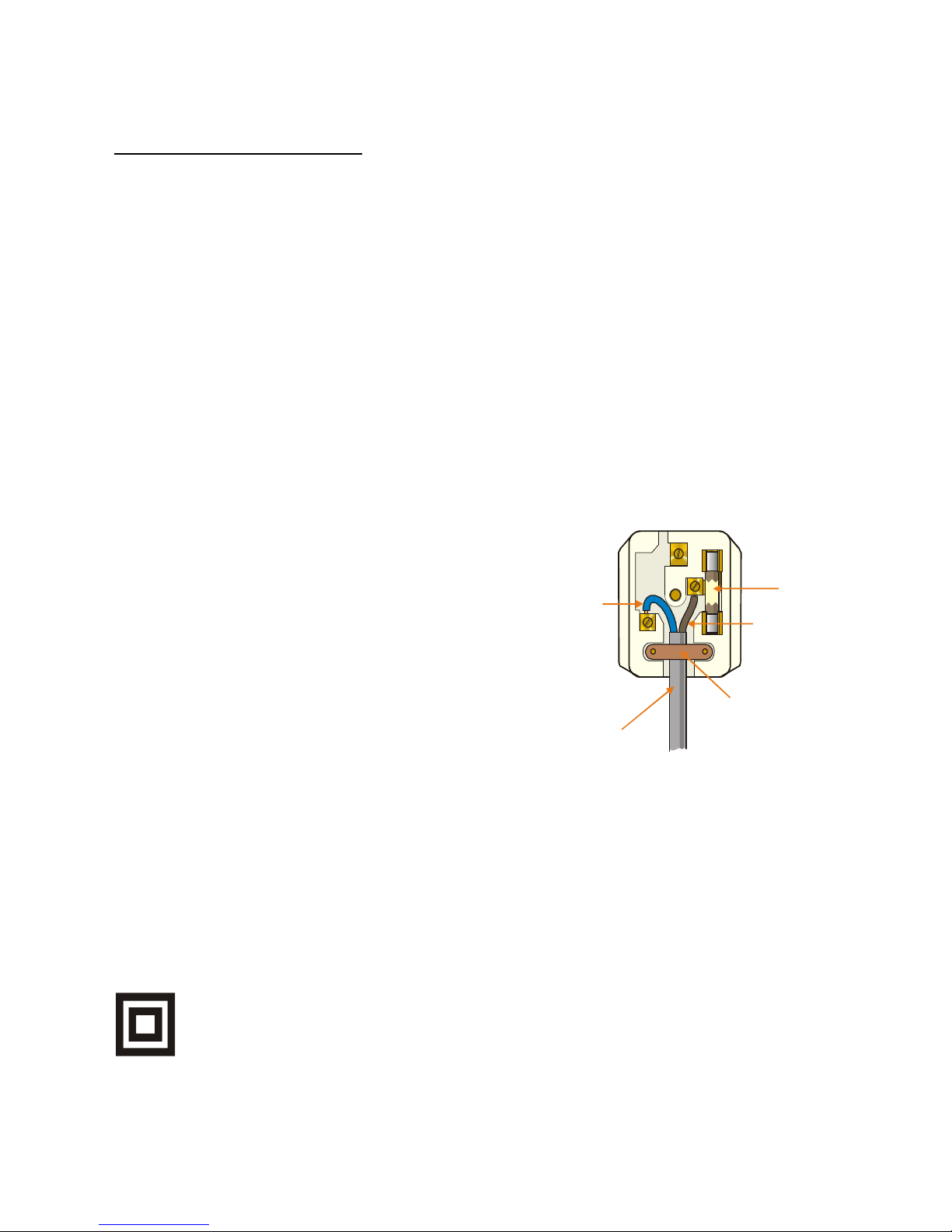
IMPORTANT
The wires in the mains plug should be connected
as shown in the diagram.
The colours of the wires in the mains lead of the unit
may not correspond with the coloured markings
identifying the terminals in your plug. Connect them
as follows:
The wire which is coloured blue must be connected
to the terminal which is marked with the letter ‘N’ or
coloured black.
The wire which is coloured brown must be connected
to the terminal which is marked with the letter ‘L’ or
coloured red.
There should be no connection to earth terminal of
your plug. If you use a 13 Amp (BS1363) plug, you will
need a 5 Amp fuse.
The mains plug or the appliance coupler is the disconnect device and therefore must remain readily operable.
How to replace the fuse
Open the fuse compartment with a blade screwdriver and replace the fuse. When replacing the fuse in the plug,
use ASTA or BSI approved 5 AMP fuse and be sure to re-fit the fuse cover. If the plug supplied with this equipment
has a detachable fuse cover, be sure attach the fuse cover after you change the fuse. Never use the plug without
the fuse cover.
If you should lose the fuse cover, please contact an electrical goods retailer.
If in doubt, consult a competent electrician how to replace the fuse.
This symbol means that this unit is double insulated. An earth connection is not required.
CAUTION
To prevent electric shock, disconnect from the mains before removing cover. No user servicable parts inside.
Refer servicing to qualified service personnel. Disconnect from the mains supply before cleaning.
BLUE
(NEUTRAL)
BROWN
(LIVE)
FUSE
CORD GRIP
OUTER
SLEEVE
4
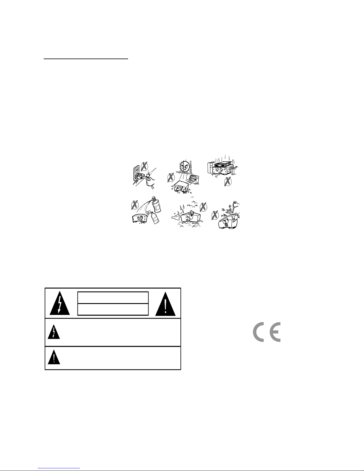
2. SAFETY PRECAUTIONS
Power Source.
This unit should only be connected to a 220-240V AC 50-60 Hz power supply. Do not connect to any other supply.
Power Lead.
Do not place the lead where it may be stepped on or tripped over. Do not place heavy objects on the lead. If the
lead becomes cut or damaged, please disconnect the unit from the mains supply.
Location.
Place on a solid base such as a shelf or in a TV cabinet or similar. Do not place near heat sources such as
radiators, fires or similar.
Do not block ventilation holes or place in a location that does not allow a free airflow.
Do not place the unit near water or in high humidity areas. Avoid splashing. Apparatus shall not be exposed to
dripping or splashing and no objects filled with liquids, such as vases, shall be placed on the apparatus. If the unit
does get wet please call an approved service agent.
Do not place any objects into the ventilation slots.
Should any of the above take place, do NOT open the unit yourself. You cause a possible safety hazard, as there
are high voltages inside.
Lightening
During thunderstorms or going on holiday, it is recommended that the aerial ( if outdoor) is disconnected, to prevent
damage to the aerial input circuits.
WARNING
RISK OF ELECTRIC SHOCK
The exclamation point within an equilateral triangle is intended to
alert the user to presence of important operating and maintenance
(servicing) instructions in the literature accompanying the appliance.
The lightning flash with arrowhead symbol, within an equilateral
triangle, is intended to alert the user to the presence of uninsulated
“dangerous voltage” within the product’s enclosure that may be of
sufficient magnitude to constitute a risk of electric shock of persons.
Battery Disposal.
When the batteries in the remote control are worn out, do NOT break open or throw on a fire. Do not place in
household waste. Contact your local waste authority for advice. Batteries shall not be exposed to excessive heat
such as sunshine, fire or the like.
Cleaning.
Do not use chemical cleaners. Use a dry duster. If there are stubborn stains, use a damp cloth with mild soap.
5
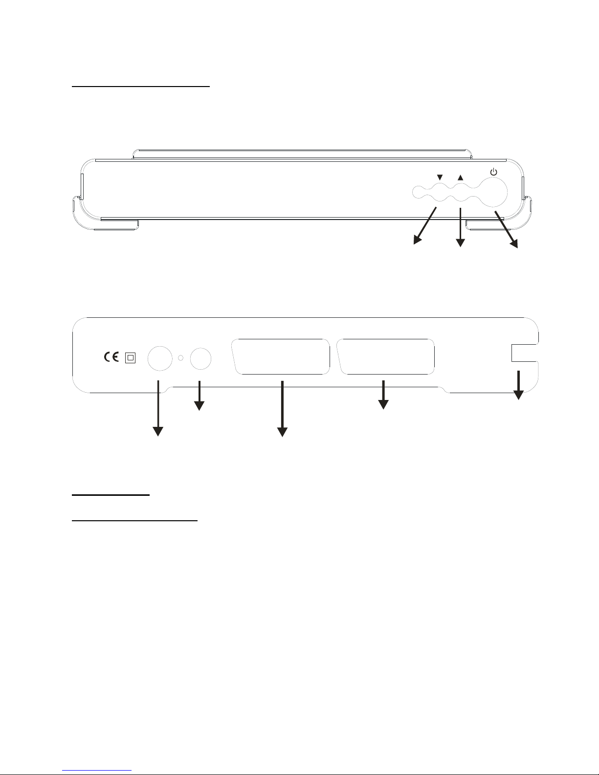
YOUR DIGITAL RECEIVER
FRONT PANEL:
P-
P+
ON/OFF
REAR PANEL:
35021962
TV VCR
AC IN
~
ANT. IN ANT. OUT
ANTENNA
IN
ANTENNA
OUT
TV SCART
VCR SCART
POWER
SUPPLY
3. PREPARING
3.1. REMOTE CONTROL
First open the battery cover on the underside of the remote control. Put in both batteries 1.5Volt (RO3/AAA)
referring to the imprinted symbols (+/-) in the battery case and put on the battery cover again. While using the
remote control, direct it towards the front side of the receiver. If the remote control does not work or the chosen
function does not work, the batteries are most probably exhausted and they should be replaced as soon as
possible. Please use only the leak proof batteries. It is best to remove the batteries from the remote unit if you will
not be using the remote control unit for long time.
6
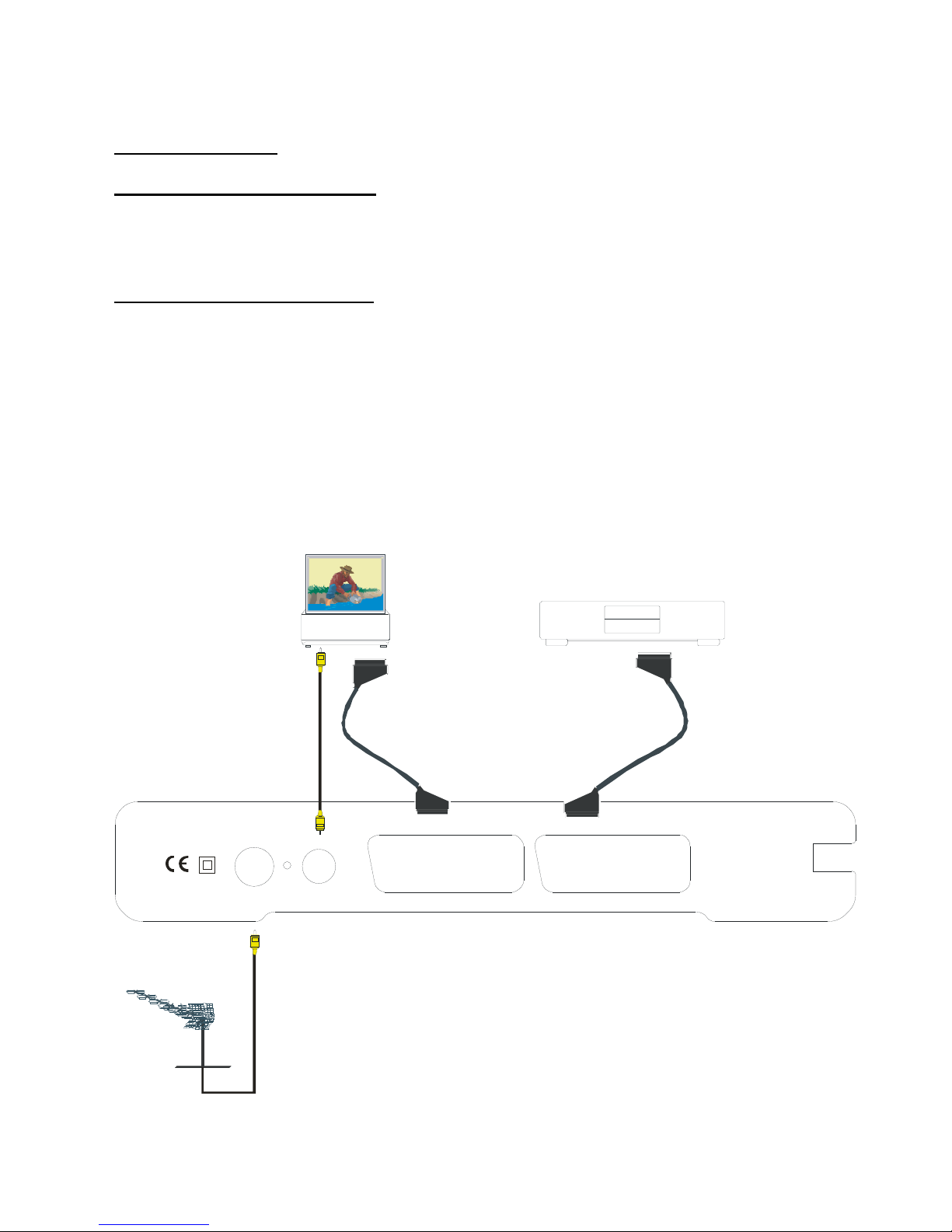
3.2. CONNECTIONS
3.2.1. CONNECTION TO THE TV
Connect your set-top box (STB) using a suitable multi-pin SCART Lead from the TV SCART socket on your STB to
a SCART input socket on the rear of your TV. If your TV does not have a SCART socket, unfortunately this box will
not be suitable.This STB has RGB or CVBS outputs from the SCART socket. If your TV has RGB inputs you may
select this in the STB Configuration menu for best results.
3.2.2. CONNECTION TO A VCR
1) Connect one end of a SCART cable to the TV SCART connector on the STB and the other end to a SCART
socket on your TV
2) Connect one end of a second SCART cable to the VCR SCART connector on the STB and the other end to a
SCART Socket on your VCR (Video Cassette Recorder).
Ø When the receiver is in standby mode: When connected device (i.e., DVD, VCD) is switched on, the device
will be automatically routed to TV.
Ø When the receiver is on: If the DVD or VCD is selected this will be routed to the TV. If the DVD or VCD is not
selected the TV will display the STB.
35021962
TV VCR
AC IN
~
ANT. IN ANT. OUT
VCR
TV
TV Aerial
AERIAL
IN

7
3.2.3. AERIAL CONNECTION
If the lead from your TV aerial is currently connected into your TV, then remove this lead from your TV and connect
to the “Antenna In” socket on your STB.Please note that reception of Digital TV requires a good quality external TV
antenna. It is not recommended that the STB is connected to an internal aerial.
3.2.4. PUTTING INTO OPERATION
Ensure that all connections have been made before connection to the mains supply. Plug the STB into the mains
supply and a RED LED will light (standby mode) on the front panel. Wait for about 7 seconds to allow the STB to
“boot”. Press the Standby button and the LED turn to GREEN. You can also press one of the buttons on the front (if
some are available), to put the receiver out from standby mode.
3.2.5. SOCKETS
· TV SCART
· VCR SCART
· Two IEC Connectors, ANT IN is the antenna input. ANT. OUT is for to output the loop through of analogue
signals.

8
4. REMOTE CONTROL FUNCTIONS
4.1. REMOTE CONTROL LAYOUT

9
BUTTON FUNCTION
1 Standby Turns the receiver on and into Standby.
2 Mute Silences received audio.
3 TV/DTV Switches between STB and VCR devices.
4 Menu Displays the Main Menu. Exits menus.
5 Up, Down, Left, Right Moves between menu items.
6 Select Makes selection in a menu.
7 Number keys Changes channels.
Enters numbers and letters into menus.
8 Guide Displays and exit electronic programme guide.
9 V+, V- Adjusts the received audio volume.
10 P+, P- Changes channels.
11 Page Up/Red Moves up a page through channel list.
Selects red option in digital teletext.
In EPG menu, changes the channels page by page.
12 Page Down/Green Moves down a page through channel list.
Selects green option in digital teletext.
In EPG menu, changes the channels page by page.
13 Yellow Selects yellow option in digital teletext.
Changes the days in 7 days EPG.
14 Blue Selects blue option in digital teletext.
Changes the days in 7 days EPG.
15 Wide Selects screen format.
16 i Displays menu help.
Enables / Disables Info bar.
17 Text Starts and stops digital teletext.
18 Back Exits menus.
19 Subtitle Turns Subtitles ON and OFF.

10
5. MENU INTERFACE
FIRST TIME INSTALLATION
When the box is started from standby for the first time there will be no channels stored in memory. A “First time
Installation” menu will be displayed. Select the TV type (screen format). To continue, press the SELECT key.
A warning message will appear, which asks you, if you want to start automatic search or not. Choose the option
YES, press the SELECT button to start Automatic search. The STB will start to search for all the stations in your
area and will store them.
5.1. MAIN MENU
The Main Menu is accessed by pressing the Menu button.
The items accessed in the Main Menu are:
1.) Channel List
2.) Installation
3.) Configuration
4.) Timers
5.) Language
5.1.1. CHANNEL LIST
The following operations can be performed
in this menu
1. Navigating the whole list of channels
2. Deleting unwanted channels
3. Renaming channels
4. Adding locks to channels
5. Setting the favorite list
Channel Table is where the channels are managed.

11
5.1.1.1. NAVIGATING THE WHOLE LIST OF CHANNELS
In the channel table moves the cursor to select the previous or next channel. RED and GREEN buttons
select page up and down.
To watch a specific channel, highlight it using the buttons or the Red/Green buttons, then press SELECT,
if the SELECT box is highlighted. The name and number of the selected channel will be displayed in the top-right
corner of the screen.
If the selected channel is password protected, a pop up menu will be displayed. If the correct code is entered the
selected channel can be watched. After the Password box has disappeared you can use the buttons to
navigate to other channels. The scroll bar in the middle of the screen shows the relative position of the current
channel with respect to the whole list.
5.1.1.2. DELETING UNWANTED CHANNEL
To delete a channel highlight it using “5/6” RED/GREEN, then highlight the “Delete” button using “ 3/4”and press
SELECT. A message is displayed to confirm your decision, if you still want to delete press SELECT once more and
the channel will be deleted, the operation will be cancelled if you select “NO”.
5.1.1.3. RENAMING CHANNELS
To rename a specific channel, the channel must be highlighted. Select “Edit Name" button and press SELECT. The
name appears on the right side of the menu with the first character highlighted. By means of “3/4/5/6” keys the
characters can be changed.Pressing MENU cancels the editing and SELECT saves the new name.
5.1.1.4. ADDING LOCKS TO CHANNELS
Channel Locking provides a password-protected access to channels selected by parents. In order to lock a channel
you should know the parental Lock password (set to 0000 in the factory and can only be changed from the
Configuration Menu), highlight the channel to be locked and select the “Lock” button, when SELECT is pressed a
password dialog is displayed. Enter the parental Lock code and the Lock icon will be displayed in front of the
selected channel. Repeat the same operation to cancel the Lock.
5.1.1.5. SETTING FAVOURITES
There will be some channels that you tend to watch
more often and some only occasionally. The favourite
mode allows the most-watched channels to accessed
more easily, leaving the less-watched channels
accessible but out of the way. Any channel can be a
favourite channel and the Channel List menu is used to
label those channels you want as favourites. Display the
Channel List menu screen by highlighting Channel List
on the Main Menu and pressing [SELECT].
Use the “3” or “4“ keys to highlight the FAVOURITE
button at the base of the screen and then, in turn,
highlight each channel that is required to be a favourite
channel, using the “5” and “6” keys and press
[SELECT]. A channel selected as a favourite appears in
the main channel list with a favourites icon against the channel name.
A channel can have its favourites status removed by repeating this procedure, to remove the icon. Leave the
Channel List menu by pressing [MENU].Once the required channels have been marked as favourite channels, the
favourite mode can be activated to allow easy access to them. Press the [MENU] key to display the Main Menu, the
“6” key twice to highlight Configuration, and press [SELECT] to display the Configuration screen. Press the “6”
key four times to highlight the Favourite Mode line and using the “3” or “4“ keys change the setting from Off to
On.

12
When you leave the Configuration menu by pressing [MENU] the favourite mode is activated. Now, changing
channel using the [P+] or [P-] keys will switch to only those channels marked as favourites in the channel list.
You can still access all the channels in the channel list by keying in their channel list number or by selection from
the Channel List screen. Alternatively you can switch off the favourite mode from the Favourite Mode line of the
Configuration menu.
NOTE: The favourite mode can only be activated if one or more channels in the channel list are marked as
favourites. Similarly, if the favourite status is removed from all the channels in the Channel List, the favourite mode
is turned off automatically.
5.2. INSTALLATION
The options located in Installation Menu are:
1. Add New Channels
- Automatic Search
- Manual Search
2. First Time Installation
5.2.1. ADD NEW CHANNELS
The receiver can search for channels automatically (searching all the broadcast frequencies for free-to-air
channels) or manually (searching one specified broadcast frequency only for any channels to be found there).Press
the [MENU] key to display the Main Menu and using the “5” or “6” keys, highlight the Installation line and
press [SELECT] to display the Installation Menu. Highlight the Add New Channels line and press “4“ to display
the options. Select Automatic Search with the “5” or “6” keys and press [SELECT]. A warning message is
displayed. This starts the automatic tuning process and searches through all the available broadcast frequencies
for free-to-air channels. Previous channels will be replaced on automatic search.
5.2.1.1. AUTOMATIC SEARCH
Automatic search is started by selecting YES in the auto-search pop
up menu. All the multiplexes are searched and a channel table is
created automatically. All channels found are stored in a sorted form
with respect to their channel numbers.
5.2.1.2. MANUAL SEARCH
In manual search the number of the multiplex is entered
manually and only that multiplex is searched for the channels.
In manual and auto search, any existing channel in the
database is not re-stored to avoid redundant duplicates of that
channel.

13
5.2.2. FIRST TIME INSTALLATION
The user can use this item to load default settings,
which had been loaded to the receiver at the factory.
To install factory settings, highlight ‘First Time
Installation’ menu and press SELECT key, then you
will be asked to confirm for deleting all channels and
settings. If you select YES and press the SELECT
button, all channels in the channel table will be
deleted.
5.3. CONFIGURATION
You can configure the settings of your box. Select
Configuration from Main Menu and Press SELECT to enter
this menu. Press MENU button to exit. Configuration Menu
includes the following main items:
Ø Audio Language
Ø Subtitle
Ø TV Type
Ø TV Out
Ø Favourite Mode
Ø EPG Preference
Ø Scan Encrypted Chans
Ø Receiver Upgrade
Ø Parental Settings
5.3.1. AUDIO LANGUAGE
Digital terrestrial television channels can broadcast simultaneous soundtracks in more than one language. This
function selects which language soundtrack you will hear when switching to a channel broadcasting with multiple
soundtracks. Highlight the Audio Language line in the Configuration menu and use the “3”or “4“ keys to cycle
through the language options. Return No Menu to normal TV viewing by pressing the [MENU] key.
5.3.2. SUBTITLE
Digital terrestrial television channels can broadcast with subtitles displayed on-screen for the hard-of-hearing. This
function selects the desired subtitle language and enables the automatic display of subtitles whenever subtitle
information is broadcast.Highlight the Subtitle line in the Configuration menu and use the “3” or “4“ keys to cycle
through the disable and language options.Return NO MENU to normal TV viewing by pressing the [MENU] key.
5.3.3. TV TYPE
Digital terrestrial television channels can broadcast programmes in a widescreen format . This format must be set
correctly to normal or widescreen TV’s. This function tells the TV the screen format so that broadcasts are
displayed correctly. In the Configuration menu, highlight TV Type and use the “3/4” buttons to select 4 : 3 or
16 : 9 depending which TV you have. This setting duplicates the settings when you first installed the STB,
therefore if you change your TV you can set the STB to match the new TV. To return to programmes press the
MENU key.
5.3.4. TV OUT
The receiver can output either an RGB or CVBS signal from the TV SCART on the rear panel. Although the RGB
format results in a better quality picture, not all equipment - particularly some VCRs - can cope with an RGB signal.

14
5.3.5. FAVOURITE MODE
This function enables or disables the favourite channel list mode by
pressing “3/4” buttons and press OK. If there is no favourite channel, a
warning message is displayed.
5.3.6. EPG PREFERENCE
Digital terrestrial television channels can broadcast simultaneous Next&Now and 7-Days electronic programme.
Highlight the EPG Preference line in the Configuration menu and use the “3” or “4“ keys to select Next&Now or
7-Days.
5.3.7. SCAN ENCRYPTED CHANNELS
If selected when searching, the “Encrypted” channels will also be stored and displayed. If NO is chosen only “Free
to Air” channels will be stored.
5.3.8. RECEIVER UPGRADE
To ensure that your digital receiver always has the
most up to date software. Please ensure that after use
it is set to its standby mode. The Receiver
automatically powers up at 3AM each day and
searches for any new information which may be
broadcast and will download this to your box
automatically. This operation will normally take
approximately 30 minutes. If you have an important
recording to make at 3AM which must not have a 30
minutes interrupt then you can disable the auto OAD
search by performing the following:
1. Press Menu button and using the “5/6” buttons
highlight CONFIGURATION and press the SELECT
button.
2. Use the “5/6” buttons to highlight "RECEIVER UPGRADE" and press SELECT button.
3. Using the “3/4” button change “Automatic Download” from Enabled to Disabled.
4. Utilize the “5/6” button to highlight “Search for New Version” and press SELECT.
5. If there is a new software version the receiver will start to search.
Do not forget to re enable the automatic OAD function after you have made your recording by repeating the above
instructions.
NOTE: If there is no new software to download, this procedure will take only about 20-30 seconds.

15
5.3.9. PARENTAL SETTINGS
Use “5/6” buttons to go to Parental Settings option. Press
SELECT button to enter Parental Settings Menu. A box asking
for the lock key is displayed. There is only one key which is set to
“0000” initially. Enter lock key. If it is incorrect, it is returned back.
If it is correct, the Parental Settings Menu including following
items is displayed: There you can set/reset locking for the Main Menu, or the Installation Menu to restrict access. If
the menu lock is disabled, there will be free access to the menu system. You can change the lock key.
5.3.9.i. Menu Lock
Use “5/6” buttons to go to Menu Lock option. Use “3/4”buttons to toggle Menu Lock Mode.
DISABLED : All menus are unlocked.
MAIN MENU : Main Menu is accessible only with the correct lock key. So the user can’t add, delete, rename,
channels, can’t set timers.
INSTALLATION: Installation menu is locked. So the user can’t add channels.
Changes will be updated after exiting ‘Configuration Menu’.
5.3.9.ii. Set Lock Key
Use “5/6” buttons to go to Set
Lock Key option. Use SELECT
button to enter new password.
New Password Menu is displayed.
Use NUMERIC buttons to enter new password. New Password is asked twice for confirmation. If both passwords
are four digits long and the same, the password is changed. It is updated after exiting the Parental Menu.
5.4. TIMERS MENU
Timer Menu is entered from the Main Menu. There is a five
column summary information, such as timer no, channel name,
start time, end time, start date and mode, for each of the five
timers.
There are two ways to set a timer. If the start/end time and date
are valid numbers, the timer can be set directly by changing the
mode from “Inactive” to “Active” using “3/4”cursors. If the
start/end times and date are invalid or if the set values are to be
changed totally, OK must be pressed while the desired timer is
highlighted in the summary list. A new window where the timer
details are to be entered will be displayed on the lower part of the
screen. The timer details are as follows:
Name: According to the type that is chosen above, “3” / “4”
keys will navigate the user through the TV or Radio list and name of the
programme is selected.
Start: By using “0,1,2…,9” keys start time of the timer is entered.
End: By using “0,1,2…,9” keys end time of the timer is entered.
Date: By using “0,1,2…,9” keys date of the timer is entered.
Mode: By using “3” / “4” keys, timer mode is selected as “Once”,
“Daily” or “ Weekly” .

16
Start, End and Date field data are entered using number keys. Current time and date are shown on the lower-right
part of the screen to help you.
After the desired detail fields are filled, one can turn back to the timer info summary list by pressing “OK” to save
the settings, or by pressing “Menu” to cancel these new settings. A set timer is cancelled (disabled) by changing
the mode to “Inactive” in timer summary list. When a timer start time comes, the Set-Top-Box switches to the set
channel, then when the end time is reached, the box goes to it’s last state.
5.5. LANGUAGE
In this menu the user can adjust the preferred language. Language is changed
by pressing “5/6” and SELECT key.
6. ADVANCED OPERATION
6.1. ELECTRONIC PROGRAMME GUIDE (7 DAYS EPG)
In no menu mode, EPG Menu is reached by pressing GUIDE
key, quit by pressing GUIDE key again. In EPG Menu all
channels are displayed. Current programme is highlighted. Use
“5/6” buttons to change channels.
Some, but not all, channels send information about the current
and next events. Please note that event information is updated
automatically. If there is no event information data available in
channels, only channel names with “No Information” banner is
displayed.
In EPG Menu, you can easily see the extended help information
by pressing INFO key and by pressing this key again you can
close this window. If you highlight an event, short event
description, extended event description, start and finish times of
event are displayed on the screen.
When the current programme is highlighted, the box is switched
to the highlighted channel by pressing SELECT key.
If you press SELECT when a next event is highlighted, a
reminder is set for the highlighted programme and a clock
appears on the screen. Programme reminders can be set to
signal that a programme is about to start when you are
watching another channel. If you set reminder to a programme,
then you will be asked for switching to that channel when the
reminder time is reached.

17
Press MENU to view the 7 day EPG. Press “5/6” to navigate
in Channels or Programmes. “3/4”key to navigate through the
channel and programme list. With RED/GREEN keys you can
change schedule time. By pressing YELLOW/BLUE you can
advance the schedule backward/ forward of a day. If you press
info key you can see easily the detailed help information and by
pressing info key again you can exit Help menu.
The starting time for EPG is the current time. You can see the
event information for the next two hours. By pressing “5/6”
key, you can go to the next/previous hours. If you press
SELECT when a next event is highlighted, a reminder is set for
the highlighted programme and a clock appears on the screen.
Programme reminders can be set to signal that a programme is
about to start when you are watching another channel. If you set
reminder to a programme, then you will be asked for switching
to that channel when the reminder time is reached.
6.2. MESSAGES
When the box receives no signal (e.g. the antenna cable is disconnected), “NO
SIGNAL” message is seen on the screen.
When there is no channel stored in the box, Timer Menu, Channel Table Menus are not accessible. Channel
navigation is not allowed. Therefore, trying to enter these menus or do channel navigation will display a warning
message on the screen.

18
6.3. CHANNEL NAVIGATION
There are two ways to navigate through the channels:
1. Pressing P+/P- keys will help you to go to the next or the previous channel in the list.
2. Pressing a number key will activate a small digit entry window on the left upper corner of the screen. After a digit
is entered, the box will wait for 2 seconds till you enter another digit. If no digit is entered during these 2 seconds,
then the box will switch to the entered number channel.
If a number that is greater than the maximum number of channels is entered, the box will switch automatically to
the last channel. Each time the box switches to the desired channel, an information window is displayed on the
lower part of the screen. The small bar on top right of the banner indicates the current signal quality. On this
channel info window there are:
Ø Current event name next event name, and their start and end times.
Ø Time
Ø Channel number
Ø Name of the channel
Ø An icon indicating that the channel is set as favourite (if the channel is not set as favourite the field is left empty)
Ø TV / Radio icon
When switching to a locked channel, lock code is requested via a window as shown in
the picture. Only after the correct code is entered, it is allowed to access to this
channel. To skip this channel, P+/P- cursor keys must be used.
6.4. VOLUME CONTROL
The volume level of the sound from the receiver can be altered with
the [V+] and [V-] keys on the remote control handset. Pressing either
key displays a bar graph of the sound volume on the TV screen.The
volume level selected will remain set, even when the receiver is turned
off and on again, until it is altered with the [V+] and [V-] keys.
Please note, that if you decrease the normal volume, the VCR output volume will also be decreased. This will
affect any recording that you are making from your set-top box.
The audio volume adjustment for the receiver is independent of the volume control on your TV set. Be careful that
both volume controls are kept within reasonable levels so that when switching from analogue to digital television
viewing, or when first turning on your TV set, the sound level is not suddenly very high.
You can silence the sound from the receiver by pressing the [MUTE] key. The sound remains muted
until the [MUTE] key is pressed again, the [V+] or [V-] keys are pressed, or until the receiver is turned
off and on again.While the sound is muted in this way, the mute symbol is displayed in the top left of
the TV screen. The symbol is removed after 3 seconds, but the sound will remain muted until the
[MUTE] key is pressed for the second time,and the mute symbol will display for 3 seconds.

19
6.5. DIGITAL TELETEXT
Many digital terrestrial television channels not only broadcast pictures and sound for programmes but also pages
of information on the programmes, the weather, news and many other topics. This digital teletext can be displayed
by the receiver.Some channels are entirely given over to digital teletext and carry no normal TV programme at all.
These dedicated digital teletext channels will not give a quarter-screen image in the EPG or the Channel List
screen. When such a channel is selected, after a brief pause, they will usually display the opening page of
information automatically.
Other channels have digital teletext pages broadcast alongside the television programme and often include a
reduced-size broadcast picture within digital teletext pages. These usually require the [TEXT] button to be pressed
to activate the digital teletext pages.In both cases, moving through the different pages of information is
accomplished in a variety of ways, dependent on the individual broadcasters, but including use of the “5/6” and
“3/4” and [SELECT] keys to select items from on-screen menus, and the coloured keys to jump directly to
particular pages.
You can exit any digital teletext channel by changing channel in any of the normal ways. You can leave the digital
teletext function of a combined digital teletext/programme channel, to return to normal television viewing of that
channel, by pressing the [TEXT] key.Calling for the information banner or any menu on-screen stops the receiver
from displaying the digital teletext pages and they are temporarily replaced by a blank picture while the banner or
menu is displayed.Digital teletext cannot be accessed when the Subtitles are enabled
6.6. WIDESCREEN
TV sets are available with screens of the standard (4:3) format and widescreen (16:9) format. When you first
installed your receiver you specified the format of the connected TV (this can now be altered if necessary; see
Configuration)Digital terrestrial television broadcasts are also made in both standard and widescreen formats. In
particular, films and dramas tend to be broadcast in widescreen format to closer emulate the cinema experience,
but even some news bulletins are widescreen. To help get the most from both TV set and programme when a
widescreen film is watched on a standard TV, or a standard broadcast is viewed on a widescreen set, the receiver
includes the [WIDE] key.So long as the receiver has been correctly set up for the TV set connected, a widescreen
programme will always be displayed correctly on a widescreen set, and a standard format programme will correctly
fill the screen of a standard format TV.
With a widescreen TV set displaying a standard format programme the [WIDE] key switches between displaying
the picture with black bars down the sides, and enlarging the picture so that it fills the whole width of the screen but
the top and bottom are cropped off.With a standard format TV displaying a widescreen programme, the [WIDE] key
switches between displaying the picture with black bars at the top and bottom of the screen, and filling the whole
height of the screen but cropping the sides off according to instructions broadcast with the programme (called 'pan
and scan').The effect of the [WIDE] key on the picture display is cancelled by pressing [WIDE] again, changing
channel or turning the receiver to standby.
6.7. SUBTITLE
Subtitle key Shows/hides subtitles of channel. When the subtitle key is pressed,subtitle ON/OFF message is
displayed.
6.8. TV / DTV KEY
If there is no VCR or DVR connected to the STB, the TV/DTV button is used to toggle between TV and STB
modes. When the STB is in TV mode, the TV SCART is not active and the TV operates normally in analogue
mode. When the STB is in DTV mode the SCART is active and the TV is switched to AV/RGB mode. When there
is no menu on the screen, pressing the TV/DVT button will manually toggle the STB between TV and VCR mode.
In VCR mode the STB will display the output of the VCR. In TV mode the STB will display its own output. If the
STB mode is not changed by pressing the TV/DTV button the SCART mode will be automatically detected. (For
example if a dvd player is connected to VCR SCART and powered on , then the set top box will immediately switch
to VCR mode. The set top box will switch to TV mode if dvd player is switched off )

20
7. TROUBLE SHOOTING GUIDE
TROUBLE POSSIBLE REASONS WHAT TO DO
The standby LED is not lit. Mains cable is not connected.
Check if the mains cable is plugged
into the power socket.
No picture or sound. No signal or weak signal.
Check the antenna and SCART
connectors
The settings you have done in the
menus have not been changed.
The digital set-top box was
unplugged without first going to
standby.
Before unplugging your digital settop box, wait for going to standby.
The remote control is not working.
· The digital set-top box is in
standby.
· Remote control is incorrectly
aimed.
· Battery exhausted.
· Press the standby key
· Check if nothing blocks the front
panel.
· Change the batteries.
You have forgotten any channel
lock code.
You should perform a “First Time
Installation”.
After you turn the receiver to
Standby mode, please note that
you have to wait 10 seconds,
before you turn it on again.

21
8. SPECIFICATIONS
GENERAL
Size 260 X 165 X 49 mm
Weight 900 g
Power consumption 6 W
Standby Low Power Consumption Less than or equal to 2 W
SYSTEM
Processor Philips PNX8300
Flash memory 2 Mbyte
SDRAM 16 Mbyte
MHEG-5 engine compliant with ISO/IEC 13522-5 and UKEngine Profile1
Object carousel support compliant with ISO/IEC 13818-6 and UK DTT Profile
RECEPTION
Frequency range 474-858 MHz
Signal level -81 dBm
Transmission standards DVB-T, MPEG-2
Demodulation COFDM with 2K/8K FFT mode
FEC all DVB modes
Video MP@ML, PAL, 4:3/16:9
Audio MPEG Layer I&II 32 / 44.1 / 48kHz
REMOTE CONTROL
Operating Distance 10 m Max.
Batteries 2x1.5V (R-03/AAA)
CONNECTIONS
UHF aerial input
UHF aerial loopthrough
TV SCART
VCR SCART
Due to ongoing developments to improve the product the specification may change during manufacture.

22
9. IMPORTANT NOTICE
DIGITAL SWITCHOVER AND YOUR TV EQUIPMENT
WHAT YOU NEED TO DO TO ENJOY WATCHING TV DURING AND FOLLOWING DIGITAL SWITCHOVER
Starting in 2008* and ending in 2012, television services in the UK will go completely digital, TV region by TV
region.
To continue using this digital TV equipment during and following digital switchover, you will need to “reset” your
digital TV channels.
Users of this digital TV product must reset their channels on at least 2 different occasions, normally 1 month apart
when switchover happens. Digital UK, the body leading digital TV switchover, and broadcasters will advise you
when to reset your channels on each occasion.
If you do not reset your channels, you risk losing some or all of your TV services during and following switchover.
Please refer to the instruction manual supplied with your digital TV equipment for help with resetting channels.
Some manufacturers refer to resetting channels as “rescanning” channels or “retuning”.
Please note that in order to receive the maximum number of available TV services on your equipment you must
“reset” channels, not “add” channels.
For more information about this, please contact your equipment supplier or visit www.digitaluk.co.uk.

Following information is only for EU-member states:
The use of the symbol indicates that this product may not be treated as
household waste. By ensuring this product is disposed of correctly, you will
help prevent potential negative consequences for the environment and
human health, which could otherwise be caused by inappropriate waste
handling of this product. For more detailed information about recycling of
this product, please contact your local city office, your household waste
disposal service or the shop where you purchased the product.
 Loading...