

Page 1

Technics
OUARTZ
OUARTZ
Synthesizer AM/FM Stereo Tuner
ST-500
Synthesizer L W/MW/FM Stereo Tuner
ST-500L
OPERATING INSTRUCTIONS
• These instructions also apply to units of different color.
Before operating th is unit, please re ad these instructions completely.
Page 2

We
want to thank you tor selecting this product and
to welcome you to the growing family of satisfied
Technics product owners around the world.
We
teel certain you wil! get maximum enjoyment
trom this new addition to your home.
Please read these operating instructions
carefully,
and be sure to keep them handy tor convenient
reterence.
These Operaling Instructions are applicable 10 models ST·500 and ST·500L.
Operating Instructions.
Contents
- Accessories . . . . . . . . . . . . . . . . . . . . . . . . . . . . .
- Before Use . . . . . . . . . . . . . . . . . . . . . . . . . . . . . . . 2
-Suggestions for
- Connections
Safety.
. . . . . . . . . . . . . . . . .
..............................
- Front Panel Controls and Their
Functions . . . . . . . . . . . . . . . . . . . . . . . . . . . . . . .
Accessories
•
AC
power supply
cord.
. . . . . . . 1
..
2 -Memory Presettings
..
3
4 -Technical Specifications. . . . . . . . . . . . . . . . .
..
5
(Reler to page 4.)
•
FM
indoor antenna. .
The
functions which differ for the two models are indicated
....................
- Listening to Radio Broadcasts
-Maintenance
-Troubleshooting Guide
... . ..
1
..............................
....................
•
AM
loop antenna
.. . ..
...
in
'"
....
..
. . . . . . . . . 1
the
6
8
9
9
10
• Stereo connection cabie. . . . . . 1 •
AM
antenna holders. . . . . . . . . . 2
~
~(A)
Note: Conliguration
Before
Be sure to disconnect the mains cord belore adjusting the
voltage selector.
Use a minus
rear panel)
be used.
10 the voltage setting
THIS TUNER/RECEIVER
HOWEVER
SIGNAL ONL Y
ol
AC
power supply cord and
FM
Use
(-)
screwdriver to set the voltage selector (on the
LlKE MANY TUNERS AND
IN
AM
lor
Ihe area
IS
CAPABLE
MONO. WHICH,
in
which Ihe unit will
OF
RECEIVING
RECEIVERS
IN
EFFECT.
indoor antenna dilIers according to area.
THE
CURRENTLY AVAILABLE
IS
OF
NO
NEW
LESSER
~(B)
(11
Ihe power supply
V"
position.)
Note that Ihis unit will be seriously damaged il Ihis setling is not
made correctly. (There
the correct voltage
AM
STEREO
QUALITY THAN
BROADCASTS
ON
THE
MARKET
YOUR
·Screws
in
your area
is
no voltage selector
is already set.)
FROM
THE
IT
WILL
EXISTING
REPRODUCE
AM
.....................
is
117 V
or
120
V,
set
10
lor
some countries;
AM
BAND RADIO STATIONS.
THIS
AM
MONO TUNER/RECEIVER
STEREO
2
the "127
-2-
Page 3

Suggestions
•
Use
a standard electrical
1.
Use
from an
air condItIoners,
Be
extremely careful not to make a connection to the electrical outlet
which uses high voltage, because there
lire.
2. A DC
Be
sure
ship or other place where
AC
power source of high voltage, such as for
Is
very
dangerous.
lor
a large air conditioner or central-heating unit
power source cannot be used.
10
check Ihe power source carelully, especially
DC
is
AC
used.
wall outlet
for
is
the possibility
Safety
• If water
Be
exlremely careful
or serious electric shock might occur. Immediately disconnect
the power cord plug, and consult with your dealer.
ol
on
a
is
x
spilled
il
water
on
the unit
is
spilled
on
Ihe unit, because a lire
• Connection and removal of the power cord
plug
1. Wet hands are dangerous.
A dangerous electric shock may result
wet hands.
2.
Don't pull the power cord.
Always grasp the plug; never pull the cord itselt.
il
the plug
is
touched by
x
• Never attempt to repair or reconstruct this
unit
A serious electric shock might occur il
disassembied or reconstructed
inlernal parls are accidently touched.
by
unauthorized persons, or
x
th
is
unit
is
repaired,
il
the
• Place the unit where it will
and
away
from
direct sunlight
Place this unit at least 10 cm (4") away Irom wall surfaces, etc.,
and away Irom direct sunlight.
be
weil ventilated,
x
• Keep the unit away from heaters, etc.
Heat can damage the external surfaces as weil as internal circuits and components.
x
•
Avoid
Insecticides might cause cracks or "cloudiness"
and plastic parls ol Ihis unit.
moreover,
spray-type insecticides
The
gas used
be
ignited suddenly.
in
in
the cabinel
such sprays might,
• For families with children
Never permit children to put anything, especially metal, inside
is
unit. A serious electric shock or malfunclion could occur
th
ticles such as coins, needies, screwdrivers, etc. are inserted
through the venlilation holes, etc.
ol this
unit
il
ar-
x
•
Turn
the unit
x
oft after use
is
lef!
lor
a long time wilh the power on, this will not only
I
~
.'
mayalso
P9Wer
61
cause other unex-
II
shorlen its uselul operation lile, but
pected trouble.
• Never use alcohol or paint thinner
These and similar chemicals should never be used, because they
may damage the linish.
x
• If trouble occurs
It, during operation, the sound
longer illuminate, or il abnormal odor or smoke
mediately disconnect the power cord plug, and contact your
dealer or
3
an
Authorized Service Center.
is
interrupted or indicators no
is
detected,
im-
Page 4

Connections
Note:
An
outdoor antenna should be installed by a
competent
technician only.
The indication AM used here includes
LW
both MW and
lor Model ST-500l.
FM ouldoor antenna (option)
in
(Necessary
reinforced-concrete
1I
FM
1
20 mm
Clamp
Shield braid
Center
Be sure the shield braid
mountainous regions, inside
antenna terminal
[J'"
(25/32
conductor
buildings,
75-ohm coaxial
Ie
cab
LJBJ:=t
) 10 mm
etc.)
(option)
is
as shown
J
(3/8
T~
or tape I
or
contacts
)
belOW:
-
~'~(
~
----
the clamp.
l
/'/
Tack or tape
"--~..:::..~~~~~~~~~C~~~~·
FM indoor antenna (included)
• Attach to a wall (using tack or tape) facing
(.~-"
of best reception.
• Tack should not
• For best reception sound quality,
i:
na
is
recommended.
• Disconnect th is antenna if
,.JJ.,
stalled.
Control input terminal (CONTROL INPUT):
This terminal
i
the purpose
external control signal.
Stereo connection cable (included)
AM
loop anlenna (included)
contact
is
used for the connection of a timer for
of
controlling the tuner by means
."
If th
AM
Be sure to connect the AM loop antenna
even when an outdoor antenna
internal antenna wire.
an
AC
power supply cord (included)
Configuration of
cord differs according to area.
(L)
(R)
is
antenna is not properly instalied,
broadcasts will not be received.
AM ouldoor antenna (option)
~
12 m (16 ~ 40
5
ft.) (Necessary
side reinforced-concrete buildings, etc.)
Use5 -12m(16
covered wire horizontally at the window.
'nyl-covered wire (option)
in
in
direction
an
FM
outdoor anten-
FM
outdoor anten
AC
To tuner input terminals
of
the amplifier
mountainous regions,
- 40 ft.) of vinyl-
na
of
Household
AC
outlet
..
-~
power supply
is
used.
an
is
in-
in-
Installalion of
1.
Pay attent ion to the following points when attaching the antenna.
• Do not attach it horizontally (to
tion).
• Do not attach it close to metal surfaces (to do so would
in
result
Wh
or
Find the height and direction of the anten na where
reception
rack, etc.
noise).
en attaching the antenna to a wal!, column
rack
is
best and then fix
Ihe
AM loop anlenna
do
so would impair recep-
it
vertically to the wall,
AM
loop
antenna
(included)
_,.~.I
Column
AM anten na
holder
(A)
i 6 >
,",,~.
J~
(included)
i
-4-
• Do not attach
do
so would result
• Do not attach it close to a tape
being used, chirping or beeping sounds
2.
Connect the AM loop antenna to the AM 3ntenna terminals
located on the rear panel of the unit.
When attaching the antenna
This type of installation may cause impaired recept ion
or
result
to the rack, a wall, or a column.
Move the anten
point of best receptio
it
close to power cords, speaker wires, etc. (to
in
noise).
in
signa I noise. If possible, attach the antenna
na
toward the right
.
ll
deck
(when the tape
to
the unit
or
AM
(included)
may
be received).
---,
left to find the
loop
anten na
deck
is
Page 5

Front
Panel
Functions
Controls
and
The indication AM used here includes
both
Their
MW
and
LW
tor Model sT·500L.
I
Power "stand
This switch turns
dary circuit power
"stand-by" condition when this switch is
set to the
Regardless
primary circuit is always
the power cord is connected to
trical oullet.
by
eb,
on" switch
on
and
olf
The unit is
by
ó"
"live"
the secon-
position.
as long as
only_
"stand
ol
the switch setting, the
an
in
elec-
the
Memory indicator
(memo)
This indicator illuminates
when the memory bulton
is
pressed.
FM
stereo indicator
(stereo)
This indicator
automatically illuminates
wh
en
an
FM
broadcast is being
received.
Note:
It will not illuminate il the
FM
mode selector is set
to
the monaural mode.
stereo
Digital frequency display
The recept ion Irequency of the
selected by using the tuning buttons or the preset-tuning buttons is indicated by a digital-type display.
Band selectors (band)
FM:
Press this button to listen
broadcast.
AM:
Press this button
broadcast.
allocation:
This bulton
quency step of either 9 kHz or
When the AM button
about 4 seconds, the AM Irequency
step wil! change to
(This slep is set to 9 kHz belore ship-
men!.)
Sel to the appropriate posilion
locality.
In
order to relurn to the original Irequency indication, press this button
lor
about 4 seconds again.
to
is
also used to select a Ire-
10kHz
FM
to
listen to
is
pressed for
per step.
or
AM
---
an
FM
an
AM
10kHz.
lor
your
broadcast
FM
MW
LW
Band selectors (band)
FM:
Press Ihis button to listen to
MW:
Press Ih is bulton 10 listen 10
allocation:
This button is also used
step
ol
either 9 kHz or 10 kHz.
When the MW button
seconds, the MW Irequency step will change to
10 kHz per step.
(This step is set to 9 kHz belore shipment.)
Set to the appropriate position lor your locality.
In
order
to
tion, press this button
LW:
Press this button
freq shift:
When Ihe
seconds during reception
the LW Irequency will decrease by 2 kHz.
So,
kHz, and then press this button.
In order to return
tion, press this button
return to the original frequency indica-
10
listen
LW
bullon is pressed for aboul 2
for example,
10
receive 153 kHz, lune 10 155
10
the original Irequency indica-
an
FM
broadcas!.
an
MW broadcast
10
select a frequency
is
pressed
lor
about 4 seconds again.
10
ol
lor
about 2 seconds again.
an
an
lor
LW
broadcast.
LW
broadcast,
about 4
Channel display
The channel number selected by the preseItuning buttons
is
displayed.
-------'"
Quartz·lock indicator (quartz loek)
This indicator illuminates when tuned precisely to
an
FM
or
AM
station.
Signal-strength indicators (signal)
These indicators show the relative strength of broadcast
signals being received by the anten na. The best condi-
tion
lor
reception,
illuminate completely to the top.
lor
FM
and AM, is when the indicators
Preset-tuning buttons
_----'
(1
(16 channel random preset tuning)
to
These bultons are used
ol
this unit, and are also pressed to select the desired preset Irequencies.
Note:
Reler 10 pages 6 and 7 for inlormation concerning preset memory.
preset FM and AM broadcast Irequencies into the memory
- 16)
These buttons are used lor tuning to the
desired broadcast station.
Memory button (memory)
This button is used when preset memory setting
ol
the preset-tuning buttons
is
made.
FM mode selector (FM
This unit automatically switches into the stereo mode wh
stereo broadcast is received. Press this button to listen
monaural mode. The stereo indicator will not illuminate
monaural mode.
-----"
mode)--..;/
ST·
in
in
500
en
the
the
a
5-
Page 6

Memory
Presettings
The indication AM used here includes
MW
both
and LW for Model ST·500l.
Importantl-----------------
II
this anten na is
AM broadcasts will
AM
lOOp antenna
th
is unit you may preset as many as 16 radio broadcast sta-
With
tions: FM/AM random presetting, After broadcast stations have
been preset as described below, any desired station can be quickIy
and easily selected by simply touching one button
received,
not
not
installed,
be
Automatic memory presetting
The
FM
broadcasting stations and
and 9 through
The
FM
"channels"
Note: When AM is automatically preset, Ihe
"on"
(I-
__
)
Memory indicator
16
lor
AM, respectively,
broadcasting stations, MW broadcasling stations, and
1 through
Channel display
16
for
FM
FM,
stations
AM
broadcasting stations will be automatical!y preset to
9 through
on
"channels"
16
for MW, and
9 through 16 wil!
"MW":
"LW": for
Notes:
1.
For automatic presetting
FM
stations, the remaining channels (through channel
be lelt empty. The empty channels can
manual memory presetting.
2 II a new broadcasting station is preset into a channel, the
broadcasting station which was previously entered
channel will be automatically erased,
3.
For AM broadcasts with extremely strong signa I transmis·
sions, the frequency memorized may be slightly different Irom
correct
the
memorize.
13
"FM":
lor
"AM": for
"FM": for
lor
frequency, If this occurs, use the manual control to
LW
broadcasting stations will be automatically preset
through 16 for
be
replaced by the new
FM
broadcasts
AM
broadcasts
FM
broadcasts
MW broadcasts
LW
broadcasts
in
areas where there are Iess
be
"channels"
LW,
respectively.
AM
Before presetting the broadcasting
stations, press to select the
appropriate frequency step for your
locality,
(Reler to page 5.)
1 through 16
stations,
lilled
than 16
16)
by
using
in
lor
wil!
that
FM
in
Confirm the names (call signs,
etc.) of the broadcasting sta·
5
tions which are preset to each
channel, and enter them
file sheet (page
•
To
check the front channels (CH 1 -
Press momentarily,
8).
on
o~
Frequency stored
channel number are displayed,
Pu1
• To check the back channels (CH 9 - 16)
Press slightly longer.
Frequency stored
channel number are displayed.
...
in
the memory and
0-'
,r,
3:
'UMHICI',
wl:J.
....
_~--
. '
1<
*
,'",,_-i;;'r~,;'
L%
in
Ihe memory and
the
8)
Set to the lowest frequency.
Tuning Press the left button to change the Irequency downward,
3
and press the right button to change the frequency upward.
-FM:
87.50 MHz
-AM:
522 kHz
-
FM:
87.50 MHz
-MW:
522
-
LW:
153
.1
Press the button and hold slightly (frequency wil! change continuouslYl·
2 Release it when approaching the above exact frequency,
and then press Ihe button again momenlarily (frequency
change will stop)
',t Press the button momentarily (Irequency wil I change each
time Ihe button is pressed), and tune
quencies .
Press. When the frequency indication begins
release.
4
The frequency will change upward, and the automatic presetting wil! begin
with Ihe next broadcasling station,
It will continue
10
preset consecutive broadcast stations.
(9
kHz step) or 530 kHz (10 kHz step)
kHz
(9
kHz step) or 530 kHz (10 kHz step)
kHz
(-
2kHz shift)
10
one of the above Ire-
or
155 kHz
to
'r%
•
2:Q~
•
Ofu
•
C3/0~
change,
(J.g,
-6-
Page 7

• "Most·recent" memory
The most-recent
"remembers"
th
is
unit
is
next time the power
memory
the FM
turned olf, and automatically tunes to that station the
is
is
or
turned on.
a system by which the unit
AM broadcast station last heard when
• "Back·up" memory
This
is
the function which preserves the preset
most-recent
if the power cord
outlet, the back-up
most-recent
week.
memory
memory
functions.
of
the tuner
memory
functions for as long
In
is
disconnected from the electric
will preserve the preset memory and
the event of a power failure, or
as
approximately one
Manual memory presettfng
Stations can be freely preset to any desired channel.
memory
and
• To prevent erasing the memory
1I
the power supply is interrupted lor one week or longer, the
memory settings will be erased.
For example:
1)
If the power cord
2)
If an audio timer
tuner for a week or longer,
3)
If a power failure occurs, etc .
If any of the above occurs, the memory will have to be reset.
The memory
power supply
switch
of
in
memory
the tuner to the
order to recharge the gold capacitor. Then reprogram the
(pages 6 and
is
disconnected from the electric outie!,
is
used and the timer does not operate the
in this
unit
is
maintained by a gold capacitor. If the
is
interrupted for a week or longer, set the power
"on"
position for thirty minutes or more
7).
I
1
"on"
(I-.OL)
Channel display
Memory indicator
While the memory indicator is
iIIuminated, press the button
5
of the desired
When the button
dicator illumination will stop, and the preset-
ting
is
complete.
• To preset channels 1 through
Press the appropriate button momentariIy,
and then release. (Preset channel
number
display.)
• To preset channels 9 through 16:
Press the appropriate button slightly
longer, and then release. (preset channel number
display.)
Note:
If the memory indication illumination stops before
you press the button,
then step
is
5.
channel.
is
pressed, the memory in-
8:
displayed on the channel
is
displayed on the channel
once
again repeat step 4 and
2
"'1
----.
_'1"'1
--_
"'1.I;ID
--
111
]_
••
,-
3
"FM"·. for
"AM": for
"FM": for
"MW": for
FM
broadcasts
AM
broadcasts
FM
broadcasts
MW
broadcasts
Before presetting the broadcasting
stations, press to select the
appropriate frequency step for your
locality.
(Refer to page 5.)
"LW": for LW broadcasts
Press the appropriate tuning
the desired broadcast.
Tuning
Press the left button to change the frequency downward, and
press the right button to change the frequency upward
• Automatic tuning
Press the button. When the frequency indication
begins to change, release the button
station will be selected automatically). Repeat this
operation until the desired station
• Manual tuning
Press the button momentarily and tune to the desired
station. The frequency will change each time the but-
is
pressed.
ton
(a
broadcasting
is
found.
Press momentarily, and then
(The memory indicator will illuminate for approx-
4
imately 4 seconds.)
Enter the name (call sign, etc.) of the preset
broadcasting
6
memory file sheet (page
This completes the procedures for presetting radio broadcast frequencies. The other preset-tuning buttons can be
preset
in
the same way by following steps 2 through
station
on
8).
the
station
6.
-7-
Note:
If the button
will begin to change, and the memory will be preset
automatically.
To stop the automatic memory presetting, once
again press either the
ton.
is
pressed continuously, the frequency
"llP" button or the
"down"
but-
Page 8

Listening to Radio Braadcasts
Have you
2
"on"
.~
_ .._
completed
Turn
radio
1
( • -
...
-
r~~~--
..
the
the
broadcasts.
)
memory
amplifier
3
~
presetting
on, and
Select
manual
(page 6 and
set
it
for
the
desired
or
preset·tuning
7)?
listening
station
to
by
buttons.
For station setection using
• To
select
the
front
channels
Press Frequency stored
momentarily.
~
memory
number are displayed.
(CH 1 -
and
For manual station selection.
Follow step
--
2,
3 of
"Manual
~
memory
--~-
!
.t_tI
j
.2_10
I 3_11 I
~
Important!-----------------..
If
this
AM
AM
loop
antenna
using
preset~tuning
channel
presetting"
-4_12 ! 6_13!
8):
in
__
the
either
• To
on page
......
--
.6_"!
received.
the
buttons
select
the
Press slightly Frequency stored
longer
7.
7_15!
&_1&
I
anten na
broadcasts
back
~
is
not
installed,
will
not
be
channels
memory
number are displayed.
(CH 9
and
ï :,....,
'!...!...I
-16):
in
channel
k.Hzch
the
Ol
~
5T·500
_.
·~iiii:._·
.----.g_
~~~w
§j
.::::::::::,:;;;:;:-
..
• 1
..
bau::
~i'P
~4
••.
4 •
•
Station
CH.1
CH.9
Memory
File Sheet
CH.2
CH.10
CH.3
CH.11
FM
mode
If the broadcast signal
terference in a stereo broadcast, set to the monaural position.
Note that the
tion.
CH.4
CH.12 CH.13
CH.5
selector
(FM mode)
is
FM
stereo indicator will not illuminate
CH.6 CH.7
CH.14 CH.15
_------../
weak, or if there
is
a large amount of in·
in
this posi-
CH.8
CH.16
-8-
Page 9
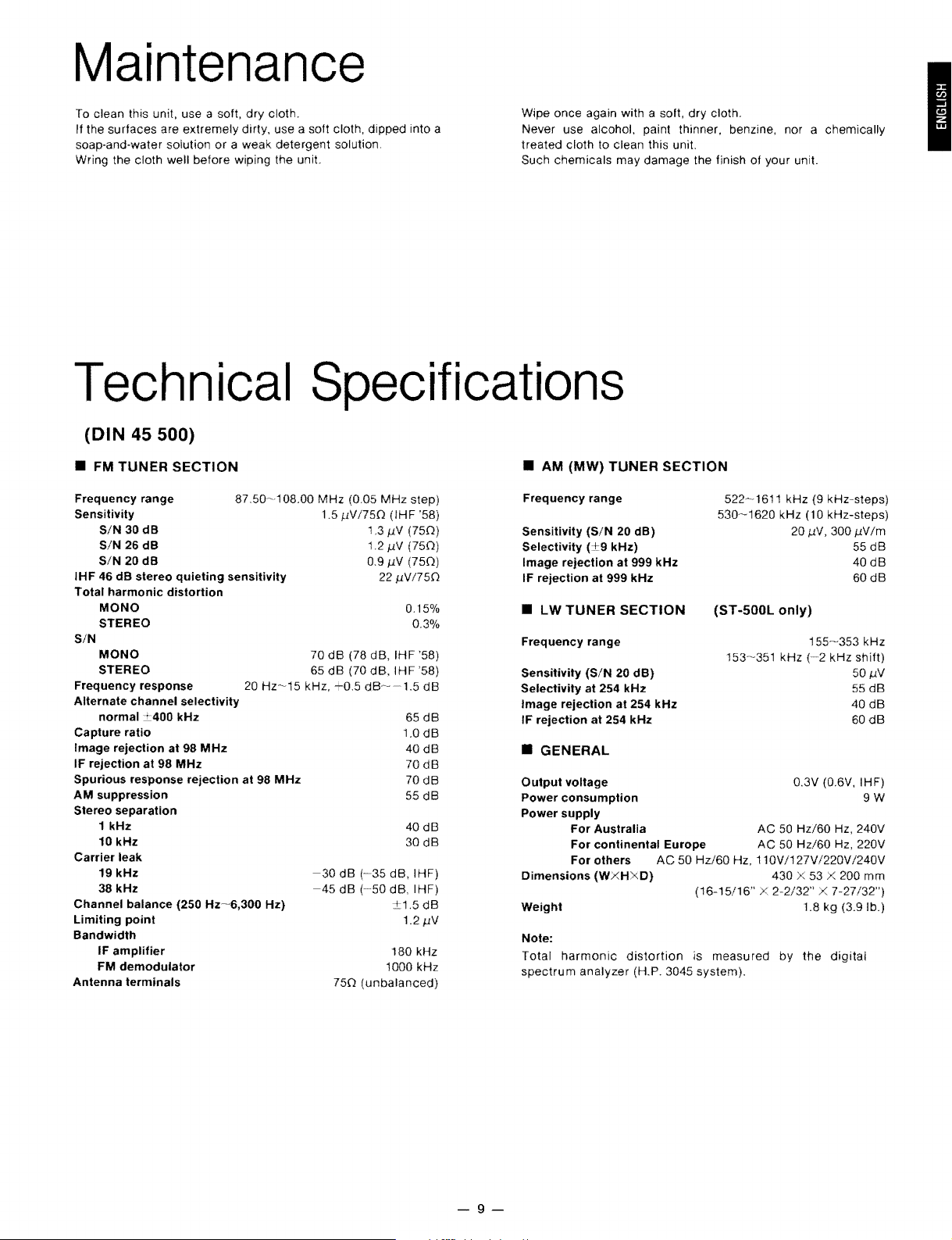
Maintenance
To clean this unit, use a soft,
surlaces
II the
soap-and-water solution
Wring the cloth weil
are extremely dirty, use a
before
dry
cloth.
or a weak
wiping the unit.
solt
detergent solution.
cloth, dipped into a
dry
Wipe on ce again with a soft,
Never use alcohol, paint thinner, benzine, nor a chemically
treated cloth to clean this unit.
Such
chemicals
may
damage the linish of your unit.
cloth.
I
Technical
(DIN
• FM
Frequeney range
Sensitivity
IHF
Tolal harmonie dislortion
SIN
Frequency response 20
Allernale channel selectivity
Capture ratio
Image rejection at 98
IF rejection at 98
Spurious response rejection at 98
AM suppression
Stereo separation
Carrier leak
Channel balanee (250
Limiting point
Bandwidth
Antenna terminals
45 500)
TUNER
SIN
30 dB
SIN
26 dB
SIN
20 dB
46
dB slereo quieting sensilivily
MONO
STEREO
MONO
STEREO
normal
1 kHz
10 kHz
19 kHz
38 kHz
IF amplifier
FM demodulator
:::400
SECTION
87.50~108.00
kHz
MHz
MHz
HZ~'6,300
Hz~15
MHz
Hz)
Specifications
• AM
(MW)
TUNER
MHz
1.5 J,N1750
70
dB
dB
65
kHz,
-0.5
-30
dB
-45
dB
750
(0.05
MHz
(IHF
j.1V
1.3
1.2j.1V
0.9j.1V
22 j.1V/750
(78
dB,
IHF
(70
dB,
IHF
dB~-1.5
1.0
(-35
dB,
(50
dB. IHF)
1.2
180
1000
(unbalanced)
step)
'58)
(750)
(750)
(750)
0.15%
0.3%
'58)
'58)
dB
65
dB
dB
40dB
70
dB
70
dB
55
dB
40
dB
30
dB
IHF)
.5
dB
j.1V
kHz
kHz
Frequeney range
Sensilivily
Seleclivily
Image rejeelion
IF rejeclion
• LW
Frequency range
Sensitivity
Selectivity at 254 kHz 55
Image rejection at 254 kHz
IF rejeetion at 254 kHz 60
(SIN
(+9
al
TUNER
(SIN
20 dB)
kHz)
al
999 kHz
999 kHz
SECTION
20 dB) 50
• GENERAL
Output voltage 0.3V
Power eonsumption 9 W
Power supply
Dimensions
Weight 1.8
Note:
Total
spectrum
For Australia AC
For continental Europe
For others
(WXHXD)
harmonie
analyzer
distortion
SECTION
522~1611
530~1620
(ST
153~351
AC
50
Hz/60
Hz, 11OV
(16-15/16"
is
(H.P. 3045 system).
measured
kHz (9 kHz-steps)
kHz (10 kHz-steps)
20 I.N,
-500L only)
kHz
(2
50
Hz/60
AC
50
Hz/60
/127V1220V
430 X 53 200
X
2-2/32"
by
the
3001.Nlm
55
40
60dB
155~353
kHz
kHz
shilt)
40
(O.6V,
IHF)
Hz, 240V
Hz, 220V
/240V
mm
X 7-27/32")
kg
(3.9 lb.)
digital
dB
dB
j.1V
dB
dB
dB
9-
Page 10

Troubleshooting
Guide
Belore requesting service
a minor adjuslment on your part may eliminate Ihe problem and resto re proper operation.
11
you are
in
Authorized service centers (enclosed with th is unit) to locate a convenient service cenIer, or consult your Technics dealer for instructions.
doubt about some
lor this
unit, check
ol
the check points, or
Nearby
(Mulli-path
mutual interference
received
(direct
nearby
Ihe
chart below
il
Ihe
Probable cause(s)
building
waves)
buildings
distortion
directly
and
or
moun
is being caused
of
broadcast signals
from
the
signals being reflected
or
mountains
lor
a possible cause
remedies indicated
n.
transmitting
by
station
(reflected
the
ol
the problem you are experiencing. Some simple checks or
in
Ihe
chart do not solve
Ihe
problem, reler to the directory
Suggested remedy
•
Try
Irom
reducing
treble
• Set
the
(Note
monaural sound.)
• Try
changing
dirèction
• II
an
indoor
outdoor
• T usi an anten
Try
changing
•
direction
• II an
indoor
outdoor
•
Try
using
the treble
lone
con trol
FM
mode
that the broadcast will then
the
ol
the anten na.
anten na is being used, change to
antenna.
the location,
ol
the antenna.
anten na is being used, change
antenna.
an
antenna
sound
ol
the
selector
location, height
na
with
with
by
amplilier.
to
the
more
height
more elements.
turning
mono
be
heard as
and/or
elements.
and/or
Ihe
position.
10
an
an
ol
ning
buttons
ol
th is
unit
have
not
•
minutes
then make
or
more
the
to
perlorm
memory
the
charging,
presetting again.
and
10 -
 Loading...