

Page 1
Servlce
Manudl
flcoMPAcr
0l[5G
D¡G¡TAL
TRAVERSE
I
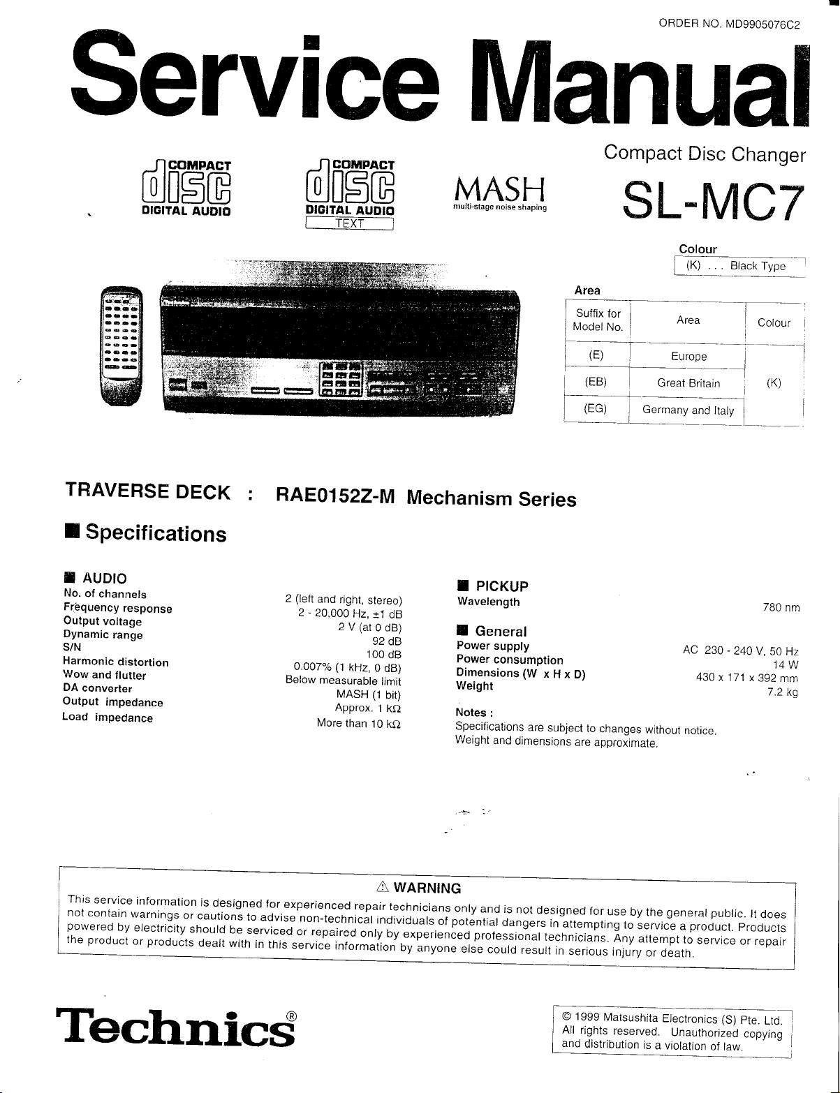
Specifications
AUDIO
DECK
:
RAE01
NCOMPACT
rñ lnf-em
IJJU-JLlD
DIGITAL
I
AUDIO
TEXT
522-M
I
MASH
mult¡-stage
Mechanism
noise
shaping
Series
Compact
Disc
Changer
SL.[IC7
-_T--
___l
Britain
B. r*f
I
i
I I
LA-r_:.
Area
Suffix
for
(t)
I
(EB)
rl
I
Europe
Great
--=1
LL-r_t_=y':ly4
_-
rye"
Colour
(K)
AUDIO
f,
No.
of
channels
Fréquency
Output
voltage
Dynamic
S/N
Harmonic
Wow
DA
Output
Load
This
not
powered
the product
range
distortion
and
flutter
converter
impedance
impedance
service
conta¡n
by
response
information
warnings
electricity
products
or
is
designed
or
cautions
should
dealt
to
be
serviced
with
in
(left
2
2-20,000
o.0O7%
Below
for
exper¡enced
advise
non-technical
or repaired
this
service
and
right,
stereo)
Hz,
tt
2V(ar0dB)
92
100
(1
kHz,
MASH
Approx.
than
0
(1
10
measurable
More
A
repair
¡ndividuals
only
¡ntormaiion
dB
dB
dB
dB)
limit
bit)
.l
ke
ke
WARNING
technicians
by
experienfeo
oy
unyon"
PICKUP
I
Wavelength
I
General
Power
supply
Power
consumption
Dimensions(W
Weight
Notes
:
Specilications
Weight
and
dimensions
onry
and
is
potential
of
professio-nar
Jre
not
dangers
could
xHxD)
are
subject
designed
in
attempt¡ng
technicians.
result
in
to
changes
are
approxtmate.
for
use
serious
AC
without
notice
Dy
generar
the
to
service a product.
Any
attempt
injury
or
to
death.
-
230
240
430
x 171
pubric.
service
780
v,50
14W
x
392
mm
7.2
rt
does
products
or reparr
nm
Hz
kg
Technicd
O 1999
All rinhtc rócan/ód I thñ!,+L^-:-^r ^-.- :
All
and
Marsushita
rights
reserved.
distribution
Electronics (S)
Unauthorized
is
a violation
pte.
copvjno
of law
Ltd.
"
]
l
Page 2
sL-Mc7
Contents
E
.
ACCESSORIES
.
HANDLE PRECAUTIONS
.
PRECAUTION
.
CAUTION
.
CoNTROLS
.
CONNECT|ONS.............
.
BASIC OPERATIONS
.
DISC GROUPING
.
CD-TEXT
.
SELF-D|AGNOSIS
.
OpERATION
.
TYPE ILLUSTRATION
Accessories
f,
-
/-----'!.\a'/
((
ffi",K#.
i=/''
AC
United
.................
LASER DIODE
OF
AC MAINS
FOR
PLAY
FUNCTION
FUNCTION
CHECKS
/*___\
-4rl1k"
power
cord
.
'--\,)
-etir/'S;a
----&A'\f\-:i\i1
Kingdom only
TRAVERSE DECK
FOR
...........
LEAD
...
.......,............
IC's TRANSISTORS
of
-*-_{"¡
for
'AGE
..".'...'2
............ 3
..........5
.......... 6
-
-
10
-
12
11
13 - 15
-
22
.... 23
cord
2
......,..........,..
.........................4
.............6
.....,.9
.'.......
........16
DIODES
and
power
AC
for others
PAGE
-
25
.
TERMINAL
.
wtR|NG
.
BLOCK
.
TBOUBLESHOOTING
.
SCHEMATTC
.
PRTNTED
.
I
CABINET
.
LOADING
.
REPLACEMENT
.
RESISTORS
.
PACKING
.
HAUI\A(III\\tr
Stereo
FUNCTION
CONNECTION
DTAGRAM
DTAGRAM
C|RCU|T
LOCATIONS.
PARTS
MECHANISM
PARTS
& CAPAC1TORS...................
MATERIALS
connection
IC'S
OF
DIAGRAM
GU|DE............
BOARD
PARTS
1IST................
ACCESSOBIES
&
cable
Remote
23
.. .....'..'...'...26
27 - 30
................
.....32
31
-
39
-
46
40
47-48
49
50"52
53-54
qq
4q
control
Notebook-like binder
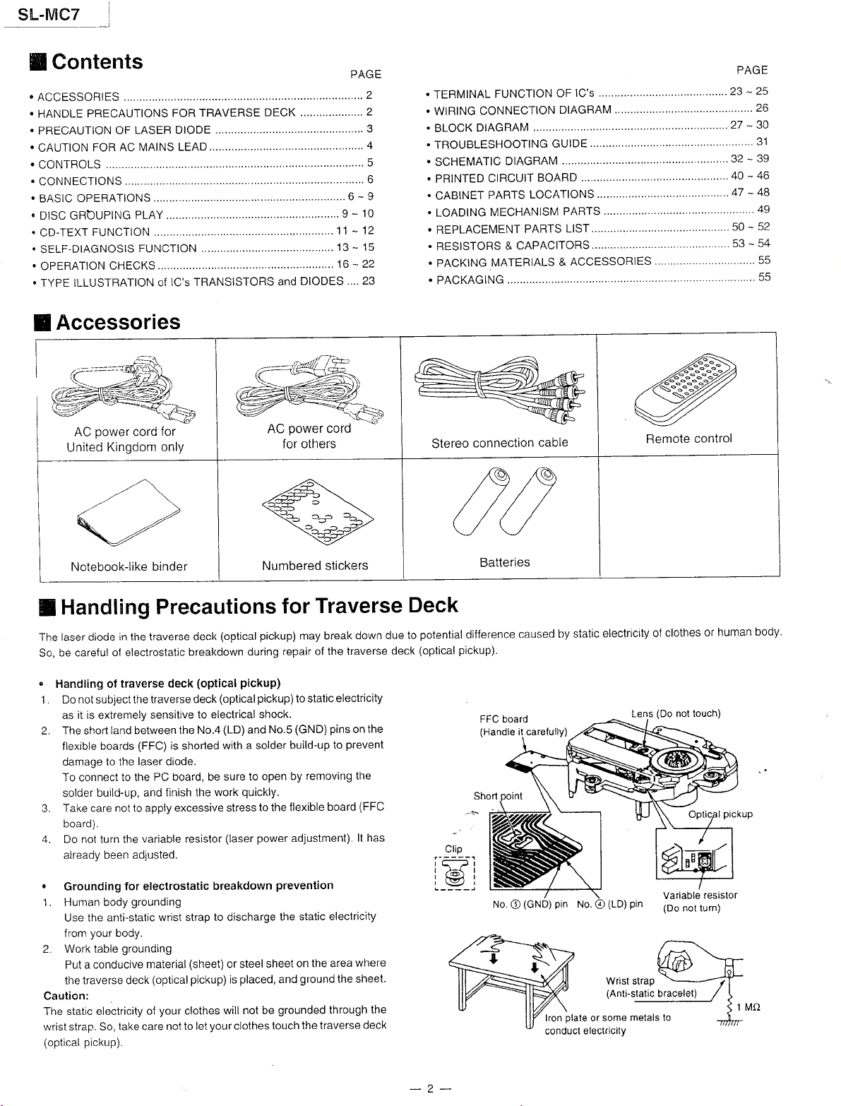
Handling
f,
laser diocle
The
be careful
So,
Handling of
.l
Do not subject the
as it is extremely
The
flex¡ble
damage
To
solder
Take care not to apply
board).
Do not turn the
a¡readv been adiusted.
.
Grounding
1. Human body
Use
from
2. Work table
Put a
the
Caution:
static electr¡c¡ty of
The
wrist strap. So,
(optical
in
of electrostat¡c
traverse deck
land between
shorl
boards
to the laser diode
to the
connect
build-up, and
for electrostatic
the ant¡-stalic
your
body.
grounding
conducive
traverse deck
take care not
pickup).
Precaut¡ons
traverse deck
the
traverse deck
sensitive to
(FFC) is
PC board, be sure
finish the work
excessive stress
variable resistor
grounding
wrist strap to discharge
mater¡al
(optical
your
(optical
breakdown
(optical
(optical
electr¡cal shock.
shoñed
breakdown
(sheet)
pickup)
clothes
your
to let
(LD)
with a solder
will not be
the No.4
pickup)
(laser power
or steel
placed,
is
clothes
Numbered stickers
Traverse
for
pickup)
may break
repa¡r of the
during
pickup)
to static electricity
(GND)
No.5
and
build-up to
remov¡ng the
by
to open
quickly.
to the flexible
adjustment).
prevention
static electricity
the
on the area
sheet
ground
and
grounded
the traverse
touch
down due
traverse deck
pins
the
on
prevent
(FFC
board
lt has
where
the sheet'
the
through
decK
Deck
potential
to
(optical
Batter¡es
difference
pickup).
board
FFC
No.
caused
(GND)
O
by static
pin
No.
plate
lfon
conduct
electricity
(LD)
Wr¡st strap
(Ant¡-static
or some
electricity
of
(Do
Lens
pjn
bracelet)
metals to
clothes
not
touch)
Variable
(Do
not turn)
human
or
res¡slor
body.
-2-
Page 3
SL.MC7
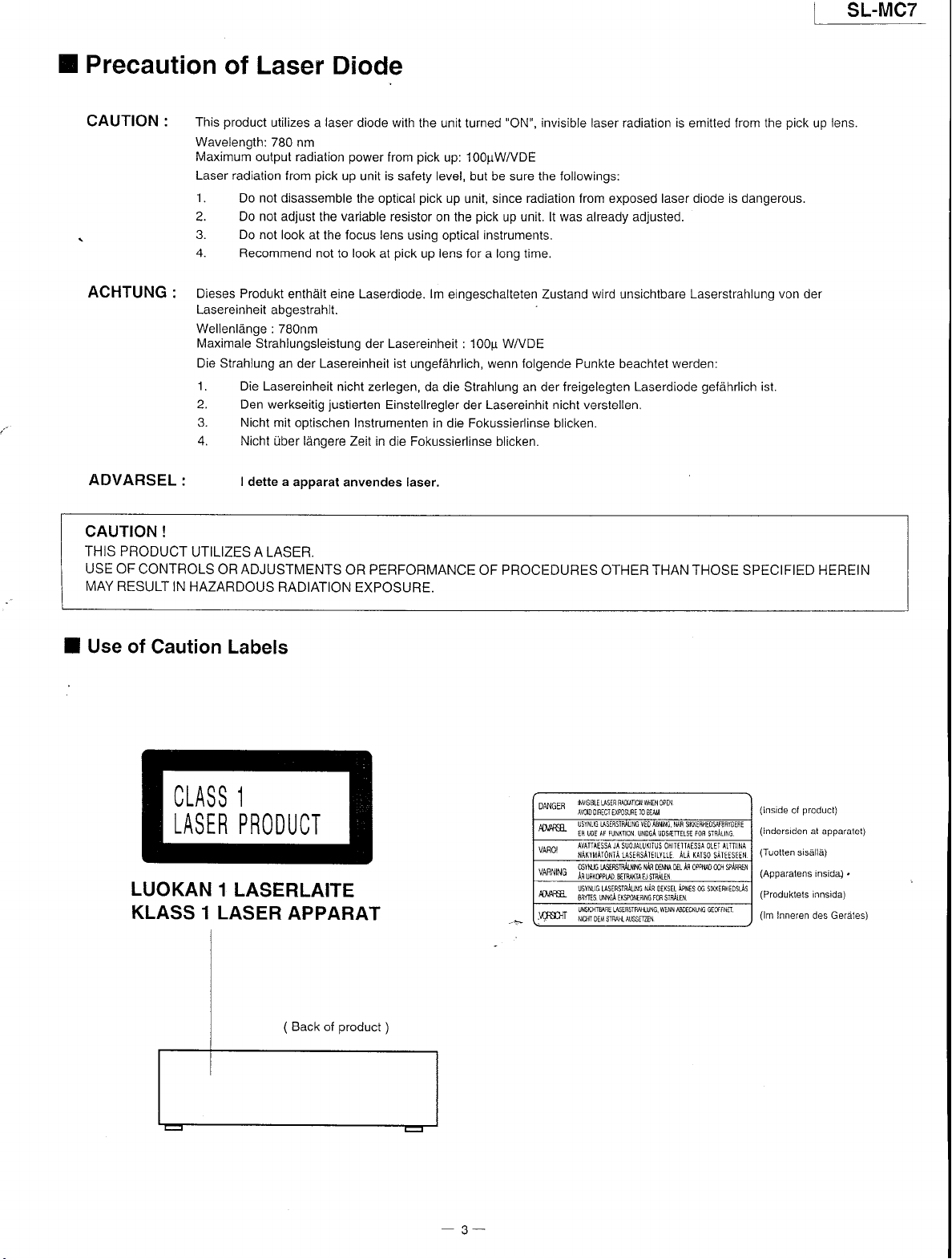
I Precaution
CAUTION: This
of Laser
product
Wavelength:
Maximum output radiation
Laser radiation
'I
. Do not d¡sassemble
2. Do not adjust
3. Do not
4. Recommend
ACHTUNG:
Dieses Produkt
Lasereinheit
Wellenlánge : 7B0nm
Maximale
Die
Strahlung an der Lasereinheit ist
'I
. Die Lasereinheit
2. Den werkseitig
3. Nicht
4. Nicht
ADVARSEL:
CAUTION
THIS PRODUCT
USE
MAY
!
UTILIZES A LASER.
OF CONTROLS
RESULT
OR ADJUSTMENTS
IN HAZARDOUS
Diode
utilizes a
780 nm
abgestrahlt.
Strahlungsleistung
m¡t optischen
über lángere Zeit
I dette a
laser
pick
from
up
variable
the
look at the focus lens
not
to
enthált eine Laserdiode. lm
nicht zerlegen,
justierten
apparat anvendes laser.
RADIATION
diode with
power
from
is
unit
safety level, but be sure the followings:
the optical
resistor
pick
look
at
the unit turned
pick
up: 1OO¡TWVDE
pick
up
on the
using optical
up lens for a long lime.
"ON",
unit, since
pick
up
instruments.
invisible laser
radiation from exposed laser diode is dangerous.
unit. lt was already adjusted.
eingeschalteten Zustand
Lasereinheit
der
ungefáhrlich,
: 100¡r WA/DE
wenn folgende
da die Strahlung an der freigelegten
Einstellregler
der Lasereinhit
nicht
Instrumenten in die Fokussierlinse blicken.
in die Fokussierlinse blicken.
OR PERFORMANCE
OF PROCEDURES OTHER THAN THOSE SPECIFIED HEREIN
EXPOSURE.
radiation
wird
unsichtbare
Punkte beachtet
Laserdiode
verstellen.
is
emitted from the
Laserstrahlung von der
werden:
gefáhrlich
ist.
pick
up
lens.
Use of
I
Caution Labels
CLASS 1
LASER
LUOKAN
KLASS
PRODUCT
1 LASERLAITE
1 LASER
APPARAT
(
Back
product
of
!J\(rtON
¡F
SUOJALLlIIJS Oh
n$R9n¡u[6
gFMreisR¡H
qHEl,l
0Ptll
UND6A UDS{rEls€
ITIIAISST
{i.q
AF
DnM 0E-
ÁpNis
\¡q
0tistl
tilNmtc(u$ GrJtfNn
Fon
sTqALt\c
¡L.iI
OLEI
0oqu0 0c' s¡Á¡rN
06 srvtFHEOsJs
(lnside
(lndersiden
[4
(Tuotten
(Apparatens
(Produktets
(lm
Inneren des Gerátes)
product)
ol
at apparalet)
sisállá)
insid4
innsida)
.
INVIS
DANa FR
-
ffiñ
'
-" *
,,^.,.,.,^
t"nt"tu
ffi
I " N
JY
8tE IISER PJ0lATlOl
-.-.
AVOIDORECTEXPOST]RE]O8TAil
ER LDE
AVATTAESSA "A
ilAIYilA.Ó,,¡TÁLASEqS¡I€I.YLLE ¡LÁ IAIsO sÁItTsELII
qsyuú
hu¡rww
üsyNr.6 LrsÉFsr¡ÁLNG
88fts uNmiEXmEn,MrcBsrF,{iFr
UNS{ryqE WtBS-ru\G.
* ''
N]ffi ffi STMNLAUSMN
)
-
3-
Page 4
s!-¡tqc_7-
E
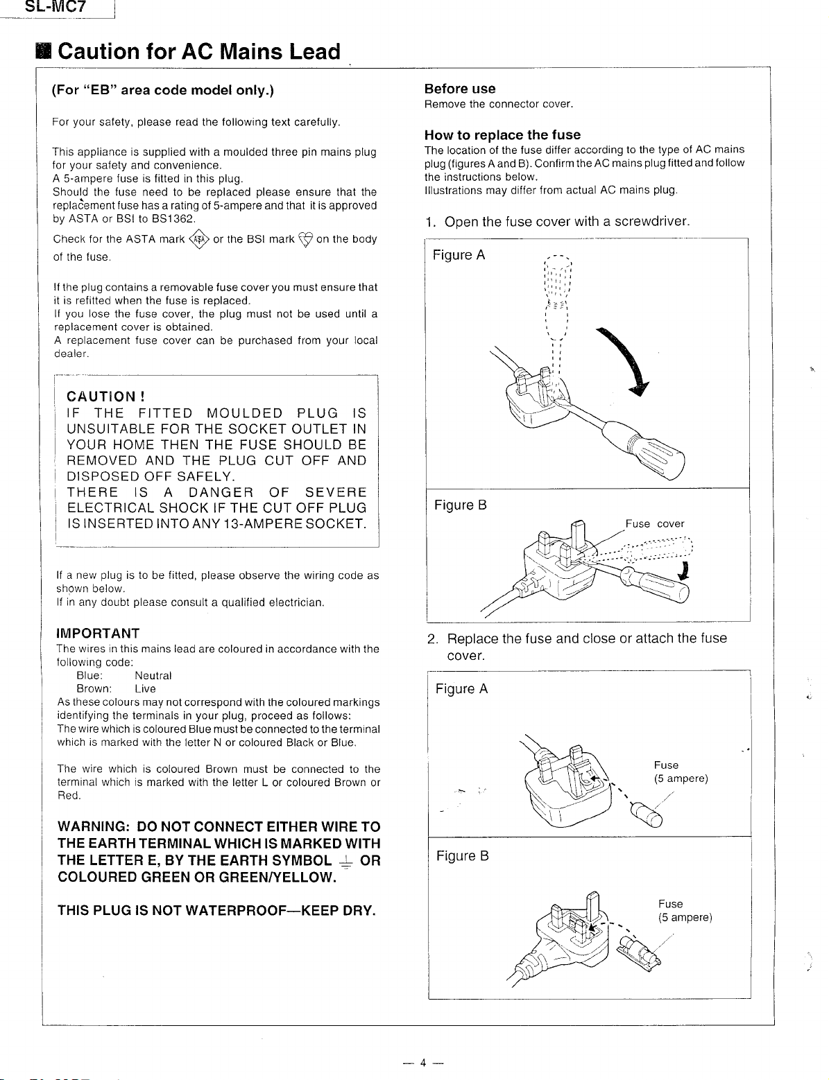
Caution for AC Mains Lead
t
"EB"
(For
your
For
This app¡¡ance is
your
for
A S-ampere fuse is fitted in th¡s
Should the fuse need to be reolaced
replaóement f
ASTA
by
Checl<
of the fuse.
lf the
it is refitted when
you
lf
replacement
A replacement fuse
oealer.
area code model
please
safety,
safety and convenience.
use has a rating of
BSI
or
for the ASTA
plug
contains a removable f
lose
the fuse cover, the
cover is obtained.
read
supplied
to 8S1362.
the
with
marf<
(@
fuse is replaced.
cover can be
only.)
the following text carefully.
pin
a moulded three
plug.
please
S-ampere
or the BSI
use cover
plug
and that it is approveo
mark p
you
must not be used until a
purchased
mains
ensure that the
on the
must
ensure
your
from
CAUTION !
IF
THE FITTED MOULDED PLUG IS
UNSUITABLE FOR THE SOCKET OUTLET IN
YOUR HOME THEN
REMOVED AND THE
DISPOSED
OFF SAFELY.
THERE IS
ELECTRICAL
IS INSERTED
SHOCK IF THE
INTO ANY 13-AMPERE
THE FUSE SHOULD BE
PLUG CUT OFF
A DANGER OF SEVERE
CUT OFF
PLUG
SOCKET.
plug
body
that
local
AND
Before
Remove the connector
use
cover.
How to replace the
The locat¡on
plug (f
the instruct¡ons
lllustrations
1. Open
of the fuse differ
igures A and B). Confirm
may
below.
differ
from actual
the fuse cover
Figure A
Figure B
fuse
according
the AC mains
to the type of
plug
AC mains
with a screwdriver.
\
fitted
plug.
AC mains
follow
and
lf a new
shown below.
lf in
plug
is to
any doubt
be
please
fitted,
consult a
IMPORTANT
The wires in this mains lead
following
As
identifying
The wire
which
The wire which is
terminal which is
Red.
WARNING:
THE
THE
COLOURED
THIS PLUG IS NOT
code:
Blue:
Brown:
these colours may not
is marked with
Neutral
Live
the terminals in
which is coloured Blue
the letter N or coloured Black or Blue.
coloured Brown must be connected to the
marked w¡th the letter
DO NOT
EARTH TERMINAL
LETTER E,
BYTHE EARTH SYMBOL + OR
GREEN
correspond with the coloured markings
WATERPROOF_KEEP DRY.
please
observe the wiring code as
qualified
are coloured in accordance w¡th the
your plug, proceed
must be connected to the terminal
CONNECT
electrician.
as follows:
L or coloured Brown or
EITHER WIRE TO
WH¡CH IS MARKED WITH
OR GREENTYELLOW.
2. Reolace
cover.
Figure
I
A
the fuse and close
or attach
the fuse
-4-
Page 5
SL.MC7
E
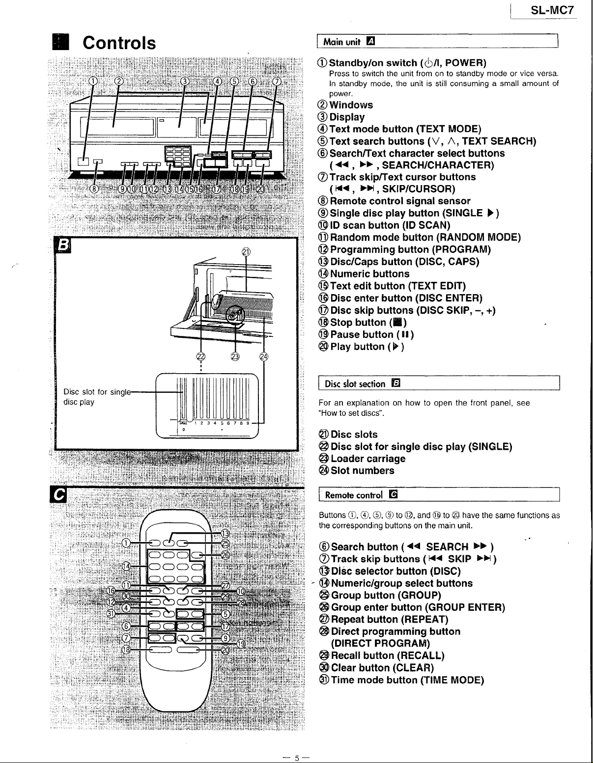
Controls
ili*;ili.
irlr,t..
:{.',,a,:,ti t,,
,¡,i:::.¡:r'::
!i|t:t:i:a:::
19.ir,r:l
t'i t I l:,:;
lii;-..
.:!,¡ir):;rl
i4iiil¡tiri
.
t¡!i: t
tj
iiii'r.,;l
Moin unit
Ostandby/on
Press lo
In
power.
E!
switch
the unit
switch
standby mode,
the
@windows
@Display
@Text
@Text
@
OTrack
@
@Singte
@lD
Onandom
@
@Disc/Caps
@Numeric
@Text
@O¡sc
@O¡sc
@Stop
@
@
mode button
search buttons
Search/Text character
>>,
(<<,
SEARCH/CHARACTER)
skip/Text cursor buttons
(K<
>>i,
sKlP/cuRsoR)
,
Remote control s¡gnal
play
disc
scan button
mode
button
(lD
button
Programming button
button
buttons
edit button
(TEXT
enter button
sk¡p buttons
button
Pause button
Play button
([)
(
( Il
F
)
(Ó/|,
POWER)
from
on to standby
is
unit
(TEXT
consuming a small amounl of
still
MODE)
(V, A,
select buttons
sensor
(SINGLE
SCAN)
(RAFIDOM
(PROGRAM)
(DISC,
CAPS)
EDIT)
(DISC
(DISC
ENTER)
SKIP,
)
mode
TEXT
>)
MODE)
-,
+)
vice
or
SEARCH)
versa.
Disc
slot section
For an explanation on how to open the front
"How
to set discs".
@Disc
@
@
@slot
Buttons
the
slots
Oisc slot for single
Loader
numbers
Remote control El
O, Q),
conesponding
@search
OTrack
@oi6c
@
skip buttons
selector
Numeric/group
@Group
@Group
Repeat
@
D¡rect
@
(DTRECT
Recall
@
@Clear
@l¡me
button
mode button
E
disc
carriage
(9
to
G),
buttons
button
and @ to
@,
on the
<<
(
SEARCH
(
button
K<
(DISC)
select
button
enter button
button
programm¡ng
(GROUP)
(GROUP
(REPEAT)
button
PROGRAM)
button
(RECALL)
(CLEAR)
(TIME
play (SINGLE)
have
@
main
the same
unit.
>>
>>
SKIP
buttons
ENTER)
MODE)
panel,
)
)
see
functions
as
Page 6
sr--Mc7
I
I
l
I
o',
c
.g'
G
L,,
c),
cLl
\-/
É EnEi E
Y
^
úY'
Et
€e e:;i
:t
É¡: ;i:á
i*q
;;
\l
$l
\|
¡;ei=.,3É¡;
\|
<grl
*!3!g;g;É5
all
óc::
dl
c|')l
FEEg
I
I
É:ÉFE
60
> é o
o^! - ; :? a
gHAb
lr€E
;
Ere*;
giig
É
o
;
-
g
g=
i¡ r¿iÉá
gr¡
iE:-
E=H:;
$EÉÉEÉÉ
H€
3
$
Ñ@
É!r
s
$e¡$É
d
:
E
i
i
3
r
ü;
e*
E=:
E$É
;fi:.
eÉ-F:ÉÉ
HsEñ
gág
F;:
*€=
g
:F;É¡
r rÉE¡É
gE
e. ii
*'E
¡f Ét
E
P
i
o
C
:.
;
ñ
?
E.
EP
hP
3
E'a
5e
3
';-s
ü
E,E >
E
gs
á;
^-8.9E
5>
NE
6:
;3 i
ge
-E
ig
H i
á{
EP
t> ;ü i ;
'E;; E;
'siE*
+;:¡
oEó:
i¡Eg
€€sl
É# É$;€
;
á
:
id
p9
EÉ
-E
lE
ig
#
p
F
J? É
i;
o
e
5
6
i
Y
I €
g
; ;
Éá
E !
és'
.^-rd_ R R +
üYs a
i*€
reec;
t i
giE
É*g
É
¡'$;eÉu
é'
ó'
o
ü
E
g
E
E
a
=-
g
3
e
i
&
.9',
rn
$1",
m,,
E
,
¡nsb-E
El 6-e F i
z i.a
f?3a
9.9
ñ5
ER
>.9
.9>
H;(
.b:
qd
e
-5c
c'e
Ég¡ÉlÉgÉgÉÉ¡ia*
gEl
sÉÉiÉsHgÉ*gsgit;sÉÉi
tg^t
&
i
E
V'
c
'ó
.:
¡n
E
o
o
L
g
o
L/
\
i;lLi
".1;:',,
n
-6-
Page 7
l
SL.MC7
.
F
HiH;F
*
H," o
ó-i
:;
i"-g
c
i
E
iE; *
!Eü
*¡Eü
:5F
HF¡ = 4 *
g¡:
;
* é
ie¡-H
ri:gt
s;Ér n
FEÉ ¡
gi!;eNE
i ñ iE
F -
i E
; -.a É¡ ¡á i
g
ü
f
á
É*
n n*
8 .¡
ó
o
=-::E
s
t*
ifi_*;r
UE €*" H
ña
o I =
J:
I 3 ;
g
H
qE
E 'g F
:F
É ;
:;
É :
8q sE ?
á"*
$l{
E
É
ÉS
rÉ -*e
E;
q
-
= ó
ü
,'
*
: :F¡
!
í
a
E
5
s"
f
s
_¿ f;¡ fg+É
ur -ÉÉá
e'EEEfiq
g
a 9
¡¡
!s
T¡
sg*
iit
g€E
;E: sÉ
¡ I
N
'2
É
;
i
s
Fi
;
F
y
E
E.
z
E
e;
I
áÉl .c5¡
$¡i
E
,¡
ü
f
¿
É
F
a
: P
^9
¡i
:; ;
Eu
*! H,ÍáHÉ:E
ÉR XCÉ:qe6o
iE :8"s:É;E Fi
9: :;9Fs9q
:d
5e :¡.&i5R *+
;é :Í¿s6ügs- óu
;o tFP;;:
E6
:p 3*ia¡;É :B*É.
áEp
'-ó
¿ É3
8*oH
E=.Éi
oc
Y."
É¡Fa_
;:;nt
-
:deós
:5bFij gF
!
t
3 o=d ; -
á 3e!*E
s!s(,E
i+3EE'; ;g
gp
l8
gE
,e
9p
=ó
Hi 3
$o
(eJ
e
!
A
I
c
r
5
Jr
5
ctáexEü
eÉii;e;
IgE;E:F
36
do
;ú
iig.S
H:i€:;
3
g
i'
ó
E
á
ú'o
r I
3
!¡
a:
^9
;o: I
3¡
;É
üg
¡¡
ec
=E I E
F; O I O
:ó a
á: á t ó
É:
-q
Es
FF
E
T T
.e e E.
E
É_
'F i
I 3
<
e
:
-.
=
o 6 0
t Éü ii Ei*¡lln
o. o.E o. o-.:rbÉü:
9F E N
-É i
* F I
E ;
I
6
3 5i
a
f a
:fr8
E
z
E s :.f:t |
,r,,
5
(!,
|
e:e:*;
:
: .HEqÉi
E tr
e
p
3
E.
:
E
g e.
u
É lit!
-^a6''t I
[--_-l at
r
I Ea
I lB;
oo
--
I |
I lÉ3
I l"s:
|
|
ác
I
a=
E I
,
u€
I
tg:
>l¡.
islsF
*lÉ!e
I
s: I
a"¡
i¿E
.9 |
ol,_'FB
o,
i 'o=
lFlü1i
6l!ig
I;H¿
I
,l
Z-^
-L
*'¡
"J
.=9
oZ
.9a
E-
=o
(/,o,
Etr
6
.g
.9
E.9
9O
pg
3
;;
2
RF
É:
9: !
-'gÉ
E
!
@
-7-
Page 8
SL.MC7
I
¿
E
5;
.s3
*É
o-9
E:
xo
".D
F$
o.:
oo
3!
g=
á8
oz
gÉ
l.a i
!9O9ó
2
cc
o
o
I
;
o
ñ =
oo
i!
Et
c¡
nú
ó-..1
o
*=
g+
99
;=
s=Va-
::s
F;P
É::
EaB
slP A
s99
-
o;€
5óa
oFl
c
oa! =
eo8
¡
e9;
;;h
>qii 3= ;?
:.ÉE
;
p'=B
€
qeü
Fts 6
s-
;
b
;9
EP
!-
ád
Oi
o
oo ='
tsE
!:
vz
og
E=
>; clo
S.s ol
g¡¿H
¿ xo =ó
ñ.=o <E
*85
Tg_E ?E
'
i;€
í99
:'¡ x
a)
.93
C:
c
,ó¿9
P€€
'? -sE sÉ
¡;
g*
:ó
:!
:d
dE
9o
ó-o
E^9
9a - X -
eo h
o96:
Etrñg
ۃq*
IsgF
.s¿9.1
tSPR i-X ==
€!;:
gü=a
¡e:
fiEBÉ q E6rE
á
É-i¡áS
z
É
J
l!
6 6
o"¿
¡:
t¡J
UA
O
I4E
qB
sj
9u
6=
EÁ
Fl
Eé
;3
s*5.9é
E.:
¿o-oui-
ó
ñ.
E
g
.E
o>
o"
ó
> Eo
a
>.'l
E os
o-?,
o
f ;
r.r,I 9€
=.8
EI;
gF
5É€
t
ñ
F=
:z
a-{
el
Eis
-^
:
'
s vlo
Yt'
iF
;
,r,.1,,
i
:i'lt
::::.
:!'
I
!
I
I
t.t il
lll
t ll
^ | I
E
)rl
al
ol
I 9l
q
fl
t3
tTl
el
I
ot
I
L:
ii"i
tl€l É ;EE
;
it'
:
¡
fr *É iti ;r
F¡'
¿
|dBi
?|
Es
Pf
Oá
E
Éi
tJ
Él I3U
gll
s
E
! o | |
É:il
i |tl
ll
?nt)
3U
i
E
o
=E
gÉE
¡ EÉ€*iil,ag¡ia
[€
É* + 1ál eeÉ
¡? ¡e BggÉ
¡¡
iɡ
*
ggl
¡
Vq*
3rü
:ao
E ó:
E
3€
>-
c á
E
sái
e 5 óó
E,I
cD
P"
c -t
p
o.<
¿
; :55:
x :^.>x,
E
Eé g 3
o +i ! i:
". ó*óo
; 9-c4
P ;i;E
= E'q I b
o
iq*o
óÉ¿5
I
a'É3gE
F
,r$
tii
ffi
nt]
uLl
-8-
Page 9
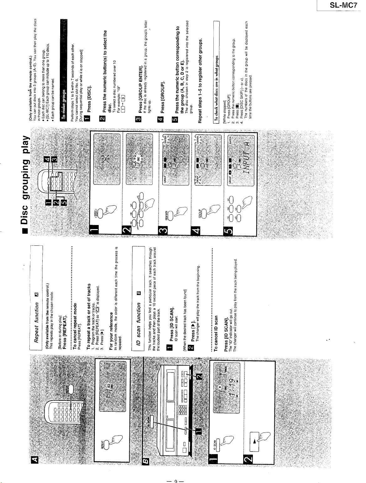
q
E
!
Pó
..9
c
g:
3
g>
9.s
:< 99
g:
¡É
Bá
ÉE.
do
::
ó¡¿.
q
Y
ó¡
::
rF! E::
A:
-ii
9eq:E 3
*ács:á
? c ii'n9
: i!
5.3:,r4.,I
s
, $
E¡ i
É
s
s
ÉE r¡ ui e:i;lflñÉ
B
i ¡ É
É;:j EÉ.
:iÉs
gÉü#
F'AE
¡ii,
pei;=
ñ
Hn
iá E E3!; lgr !i*g
Bt I ¡;c I l+l sE
lEs
q
E,l
ÉÉ
gE
Eq;
r
igÉ*g
q
E
u ü
e
s il
:
l l"l :';
É
ljl ¡ .;,
g;E
lil a?;;?ii
r¡i
fo
Ell::==
SL.MC7
ttt
a
É
oó
F3
I.s ák
É't
*á
q
o Jw
bg
S
I
€;'
o o
E.e * !,
dd
9É
.2
a
;
5
ii
H
ob
O=
tB
9.€E
l!SE
-9.¿
:;q
oa€
-,;-9
.,
g
o.?.
E lDSlRt i
0:;
ts
É *:s Pe
E óHtr
*; !!f ño
si
o.Pt
TB ÉEHT :!
hF SBá
e!:
-oU BY&
FG
F;ojcj
oc
!;
ÜP
au
r- t'
gH
=:
3H
€e P €
93 3 *
dX -
oY
ETx 7 s I
:*E
*Ée
gb:
E'ÉP
-Yq aE n 69
er; Eg :
Eft
:ó= :o QoiF
É!s
q
a
a 3
8EÉ-=
3.=
ñ-o € a-F
E
-!
:
lp'
E
e;
iE
:
:n
i
:
E
P : *
:
f
:
:
q
!
.
I
!
:"
:Eá:É
ó;;
i3
grlqi
'E eÉa
-;-E
;c
:É É!i
É
¡
!
!
a
g
3
E
a
',",i'i
- q-
Page 10
s[--ÍMc7
_l
E H€
;
s
ó 19
;
Eg
¡E
t:
I t;
s
E- i* I
ts
i
3 ; H
É
4 i; lPH
g
á ='f; x?: ;
x
gE5
Fi Í
;g
;: ¡q N
E' l="
b:;
; = vPá
Ée
!
g
á
épsq { A
g¿q:
s¿
s sH: I
ü ii;6
E ,iÉ5
g-H-g-q
o c t b
Á
T
¿
=
=
¿
ü 5
3 E
E
s
",a
? i
d
I
r
É
¿ Ee
i
E
q
e
ü r
ñ,
5E;
-ó:
'38
P; e
:e.T
i fr P9
q
:
s
2 _ E r ií Éo
3
Él É
r*El*P-HE
I =6
Y.
3 ?-cr,
i
;
i€
s
s
F
E
:
E
E
6
E
i,
e
E 3sBE,e
- E=E o:
I
o ó+o€ á
'
P
E
F
Y
o
eo
F
9U
o<
'9
EO
u9
E6
ú.s.:é
of-ri5
7'¡7,t!
É383;
[óCO=
-Ajos
| |
tl
,¡
I |
.t
i b
I I : +o
:
L
i'i
I I P s: ¿P
I I i =\
¿
I
e ;S
Li
€
I I
B
I 1
I I F
i
lx
lil I
lPl =; F.0
t6 6ñ V9 !-^
ls =t i; Heá
gu-;ó
l.!
-sggÉe
lul
E-EAP-Eü
1*l
aEaaaY
lÉl
lúl Eo999E
""**
lel
-6id+d
L I
3v
3.d
-
é3 3E
o!!
9q
oX
0c
E9
9:
e:
ss
eé
És
o;
9*
bE-
bgE
s¡sÉ
6I:l
>:o9
biF;
[=-5t
3o
9o
óo
FE
:o
go
E3 F
áo
óo
E:
gá
íE
PF f =
!o V C
;g ü
:",
ti o
o:
R: O p o
i,á
5-E
É- E
o o
d i5
HÑ
!
f
o
.e
es
f
o
o:
v,
9ó
t6i
ñ 9>
o na
t
X
s
q q-d
o
: .óEg
€ e s5F
> .9 -
S
E ;?\
o
^d
'6.
{E+
I FFq e;L
á
i:5 s3g
qÉe
s
I 159
¡o
o
i
I eXí Há.
ggá
¡
óg
E
FT
qo
-
=l]
Y:
P?1
pE-Z
eiÉ
uie
q
Ít;
EC+E
Page 11
";
l--l
€tt
eEll:
FEI
s
6
0l+)
-b
P
o
É
) s i.gl
; É JTI H
Edl\l =
.,;l€l
-o
=
E H I:I H
áta
;
.E
I
Hlil
:
6 - I Ol
g
: lfl fr.
g
Él=l ^Y
;EB
ÉEi E]
i
f
lñl 3
l¡l
g
Inl o
I
=
t:t
ñ
lül
E @
o
:
I
o
o
=
<6
hh
E=
>
ñ9
= ¡X
¡
x:
()
aJc
< 92X
t¡l
ig
@
i'o
gd
F
,
.E.q
x
: ¡¡J
E F EE
v)
=
5
:-
aa
"
éF'
a
éÉ
6.üó.ó E
(ltt><
ñ
Éá
s
ü.
I Á! | I
:
e
! o:
:
e
E
! r
q
É
ó
9
=^
-P :; l8l ñ
¿' s E:
a
9 _9_¿ lst Y
8",;r; l;l
; !-:
B
5g
-
s, .É I
a
Eg
E
!
á€tse€ l{l Et
fL
*
ipBE,:
F:€;,iE
fl *
s3
I lE
Éo
I lE
-5 i |
ttov
¡ lñ a
g.E
| |
;E
lEtl
¡E
l;l
€E lgl
l3l R
3=
lil
c¡
l_l I
3i:
ltl ;
E:'s l$l FE
lÉl
tr ÉE
o
;
¡
s E
€
F
.E
{
E
;
5;
áE
É9
o=
oq
o5
,^
a=
<6
'
\6
*
a, v9
ttl
o
I
/\
Y
¡t
o
<
g
=
r €o
F
x
x
u¡ T.: s
L Ll!
H.
q.t
@
q=
9É 9e€
u
o-: o-d9
o
EE
.;é
-éü
o
@"
c
H*
¡¡
o
p¿
s;
ó-
9!
SL.MC7
L
.,
o
elr
66:
s3= E:5
h
>y
c H b
:9]
ti¡e
oc*
FEE
=!q
3¡É
P== .-5€ :
:;; E¡g ñ
--oX
EH
g
!É3 €EHiE
XF!
!'E ü É ó'!5=
E!!
¡39
-
ñ
E
E
3E
f -ó
:ÉE
E6o !
::;
eE,Í
i?s €
.!
o ñ
9 ,!:!
?=E'F
I
E
c é;
¡áÉÉE¡Éf;5F
.9
o
F
x
IJJ
F
I
o
C)
m
BI
EE
BE
-{u
0¡
0000
000ü
0000
B
0
I
l
g
É
P
o
irk
tlJc¿
oEtr
=
FlE
H á;€
q
q,
I o :ó
d
E
E
.E
!
ñ
ó
F
t
*É
oc
é¿
6F
É -..q
7 ;-
0>
6
E
9c!
É
!
!
E
t
t<
I
o
>r
óó
<:
>9
E(t
?z^
€ EE
; c".
B
; ái oqFEH: iu
g
r
E
;
i
i = _Ets
F3
."!
!s :ü-1;:;
É-a
E;,:=s{5€!BÉ
>:
,3'9XE:
É;É:Éf;
¡HE?"€
€g_58ÉH
*ü€iPcs;*
; e¡üelE;:Hi:g
€gE;i:;:;€;E
P
É
Er¡s:Es;;i;;
g.
tri€-;*f-;úgüE
FEE
É
iÉ
!á ;;=€siB":s!cH
o
3
Ci¡sF!5Et;¡á!
sÉ
irÉ
ÉÉ
É;E
:
FÉ
ci
":
:i
-tt-
Page 12
SL-M9I_
_l
u3
X!
ulI
Fg
E9
(Lt
a
.q
ElÉ
,otl
@:ll
o>t¡
úótl
E6ll
9>tl
*ñtl
q>tl
tsotl
>;l¡l
ñ
-.
ñ
ü
E
9
c
ñ
PI
E X 9 I
E
; ; I9.I
o
ü
óeÉlEl
-
v o , Et
e E F" lil
: b - i; l.sl
E' F r ;; lsl
; i Eg I'dll
s É
* lEl
g
; ldl
€
3
6
p
EIE
oiB
i>
l*l
:
l9l
d :
¡
ltl
rl
9
F
lcl
i-9r
Fo;A
5g;?
>L- V
*Ít:v
éñ;¿
EJ
flF,,t--?.Eil
iffil
l,rili'tl,l
[:,:]¡:'
B
t-t
t.t
ll
:
9:
;^
P6
-V
I
E l-l
: ¡0t
É
.-
e l8l E !
:
I l>1 F ;
E- lSl i+€+
e=
:ü lFl €üE'ü
Ei l,¡l ;Fúk
oP l'=l
E=
p
6
lEl € ¡
e
16l
s
lal
tEt E=3=
€l!;{P
| el >=YE
F8 I¡I e.EÉÉ
ii
<o U
$¡i:
I
ltl
?"ii
-No9
E
E
.q
otr
=ó
cb,
oE
Eo
o5
i=
PR 2
;c
:<F ó
AF
oÁ
EÉ 9ñ:
Eq
!d
,\; lrrrñ
E: ;=i;
g
ñ
6FÁ
>o É I o6
E:i
gfü
F
z
o99
3EÉ
;tr
>
qL+
oo6
:!¡o
sdÉ
iT,,
¡,
:Yá
,'on
3L:rh
!
erg
:.ó
Bg b !
n!
Fg s
EE
ñ¡ J v
ñi
RF 4;4
aú :Fx 9e
i.s
N>
á
* ó
E
E
s.
y
sg
üE Eq
::3 85
E.E
E;;
¡:
cf
!tr-
{€s *€: ;:
cis
s9e ES
A-áE
FEé
i;E .e:; aI
:5: :FO Fd
:;
.n l--)
?ll>J
o
o
E2 5!qE
¡l
E
!
Ee
ü: €:*f; i
i:
:B
9.2
EÉ Y l;t e E
Ee ::Eáqü
r€ ;aÉ8:c
e6
6E!
:IH'
6EE
;:q
fi
E: EEEEqü "S T
i;i eFá¡Ési
é
o .f
:óÉI
"
= dE
Tf !!
5:;5
o
o 9!
€E*:
;E*ÉS:
olJ:
99ñ:+N
ÉEó¡ÍE
gioEü;
bñ6E::
soc!X! O
iñ€ÉHi
€
E 69
e ;
gÉ
É
t
:
.=-
E
E
=
i s : 3: H
Éaü
a
c P o
4
<
= , I ñü
t
I
o
$ s F. Xi H!
I
i a Ft Fa F€
i
g
NOtr E
: X=
., ;;
=
r¡{
i
8
E
o
=
ú
E iY
9
E e!, É
3
e
E
*!,;;;
FÉ
l¡J¡
Ec 73sE
É $3 $É
q
.9
i:
á*@
E:
:
EA
1
+s
y:
'
X'::
e
tg
OÉ
;
i
,lÉg?
3
¿?
F
9F áY
o=
E6
:E
.Yf!
F:t :: c
zz
9;:EB I
E HA; fi
1i6-=
5
9a:.e E
oi9i:
ÉgÉT
E
5ES,J¿F
c F=:X.9@
..-..4>A-=q
5E;É5gS
3 E
?s 9
bo"
g5
á
X
e
!
i
É
ó
ó
:
E E
,fr¡6Éóie'
E
-
9t
c
-*d
o=
X 9
: e 99
q
é!
c
69P¡
coó;
-12-
Page 13
SL-MC;
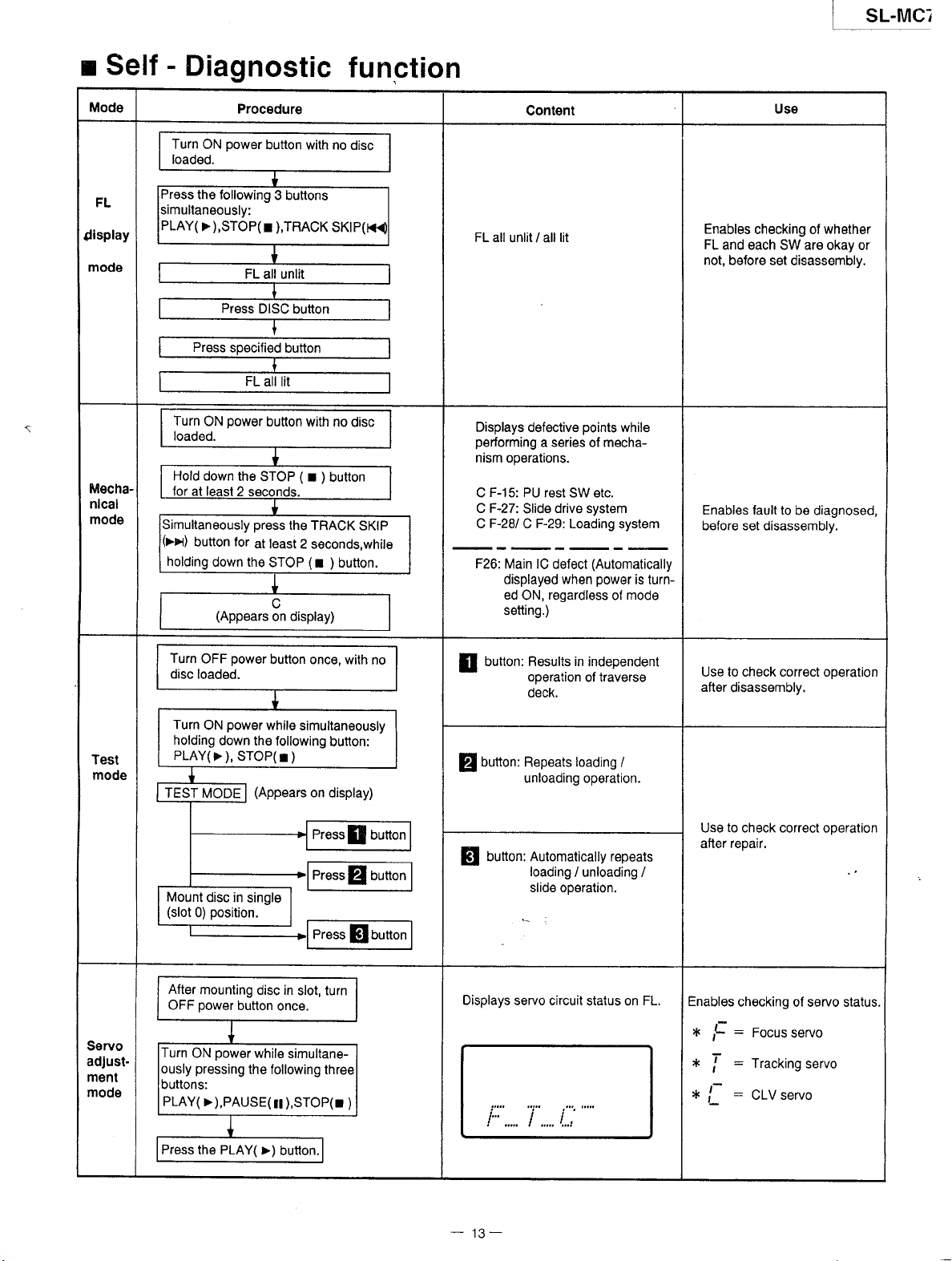
Self
r
Mode
FL
{isplay
mode
Mechanlcal
mode
-
Diagnostic
Procedur€
the following
Y(>),STOP(r
Hold down
Simultaneously press
button for
holding
down the
the
at least
3 buttons
),TBACK
(
STOP
r ) button
the TRACK
2 seconds,while
(
STOP
function
SKIP
r ) button.
Contsnt
FL all
unlit / all
Displays defective
performing
nism ooerat¡ons.
F-15:
C
C F-27:
CF-281 C F-29: Loading
F26:
Main lC defect
d¡splay€d
ed
setting.)
lit
points
a series
PU rest SW etc.
drive system
Slide
regardless
ON,
mecha-
of
(Automatically
power
when
of
while
system
¡s turn-
mode
Use
Enables
FL
not, before set
Enables fault to
before set disassembly.
checking of whsther
and each
SW
disassembly.
be diagnosed,
are
okay or
Test
mode
Servo
adJustment
mode
Turn
OFF
disc
loaded.
Turn
holding
PLAY(
TEST
MODE
Mount
(slot
0)
After
mounting
power
OFF
urn
ON
pressing
PLAY(
power
button once,
power
ON
>
disc in
pos¡t¡on.
power
>
),PAUSE(
while
down the following
STOP(
),
single
button
the following three
simultaneously
r
)
(Appears
disc in
slot, turn
once.
while simultane-
lt
),STOP(r )
with no
button:
on
display)
PressI
Press
fl
Press
fl
bunon
button
button
button: Results in
E
p
p
Displays
operation
deck.
Outton: Repeats loading
unloading operation.
Outton: Automatically repeats
loading
slide ooeration.
servo circuit
"i,,,,.
i.:,::,....
independent
of traverse
i unloading /
stalus on
-'
¡.,.,
Use to check correct ooeration
after
disassembly,
/
to
Use
check correct op€ration
after repair.
FL.
Enables
*,
*
*,
checking
:
Focus
,f
:
Trackingservo
|
:
CLV servo
,f
ol servo status.
servo
Press
the PLAY(
>)
buüon.
-
13
-
Page 14
SL.MC7
l
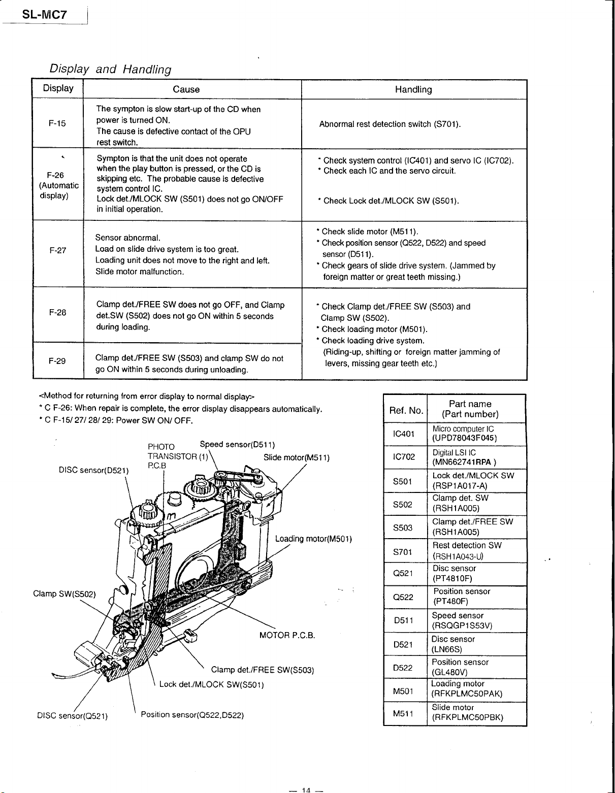
Display
Display
F-1
5
F-26
(Automatic
display)
F-27
F-28
F-29
and
Handling
The
sympton is
power
is
turned
The
cause is
defective
rest switch.
Sympton is that
when
skipping
play
the
etc. The
button
syslem control lC.
Lock
det./MLOCK SW
initial
in
ooeration.
Sensor
abnormal.
Load
on slide drive
Loading
Slide motor
det.SW
during
Clamp
go
Clamp
ON within
unit
does
malfunction.
det/FREE
(5502)
does
loading.
det./FREE
5
seconds during unloading.
Cause Handling
slow start-up
ON.
contact of the OPU
the unit
is
probable
(5501)
system is too
not
move to
SW does not
not
(3503)
SW
the
of
CD
not
does
pressed,
operate
or
cause is
the
defective
does not
great.
the right
go
OFF,
go
within
ON
and clamp SW do not
when
CD is
go
ON/OFF
left.
and
Clamp
and
5 seconds
Abnormal rest
Check system
Check each
Check Lock
Check
Check
sensor
Gheck
foreign matter
Check Clamp det./FREE SW
Clamp SW
Check loading motor
Check
(Riding-up,
levers,
detection switch
control
lC and the servo circuit.
det./MLOCK SW
slide motor
position
(051
gears
loading
missing
(M5
sensor
1).
of slide drive system.
great
or
(5502).
drive system.
shifting or
gear
(3701).
(1C401)
and servo
(S501).
'l
l
).
(Q522,
D522) and speed
missing.)
teeth
(5503)
(M501).
foreign matter
teeth
etc.)
(1C702).
lC
(Jammed
and
jamming
by
of
<Method
'
F-26:
C
'
C F-1
DISC
Clamp
SW(3502)
DISC
sensor(O52
for returning
When repair
5/ 271 281 29:
sensor(D521)
1)
from
error display
is
complete, the
Power
SW
PHOTO
TRANSISTOR
P.C.B
Position
to normal display>
error
display disappears
ONi OFF.
Speed
(1)
Clamp
Lock
det./MLOCK
sensor(Q522,D522)
sensor(D51
Sl¡de
MOTOR
det./FREE
SW(S501)
automatically.
1
)
motor(Msl
l)
Loading moto(M5O1)
P.C.B
SW(S503)
Ref. No.
1c401
tc702
s501
s502
s503
s701
Q521
Q522
1
D51
D521
D522
M50l
M511
Part name
(Part
number)
Micro
computer lC
(uP078043F045)
Digital LSI
(MN662741RPA
Lock det./MLOCK
(RSP1A017-A)
Clamp
(RSH1A00s)
Clamp
(RSH1A00s)
Rest detection
(RSH1A043-U)
Disc
(PT481
Position
(PT4B0F)
Speed sensor
(RSQGP1S53V)
Disc sensor
(LN66S)
Position
(GL48oV)
Load¡ng motor
(RFKPLMC5OPAK)
Slide
(RFKPLMC5OPBK)
lC
)
SW
det. SW
det./FREE SW
SW
sensor
0F)
sensor
sensor
motor
-
-
Page 15
SL.MC7
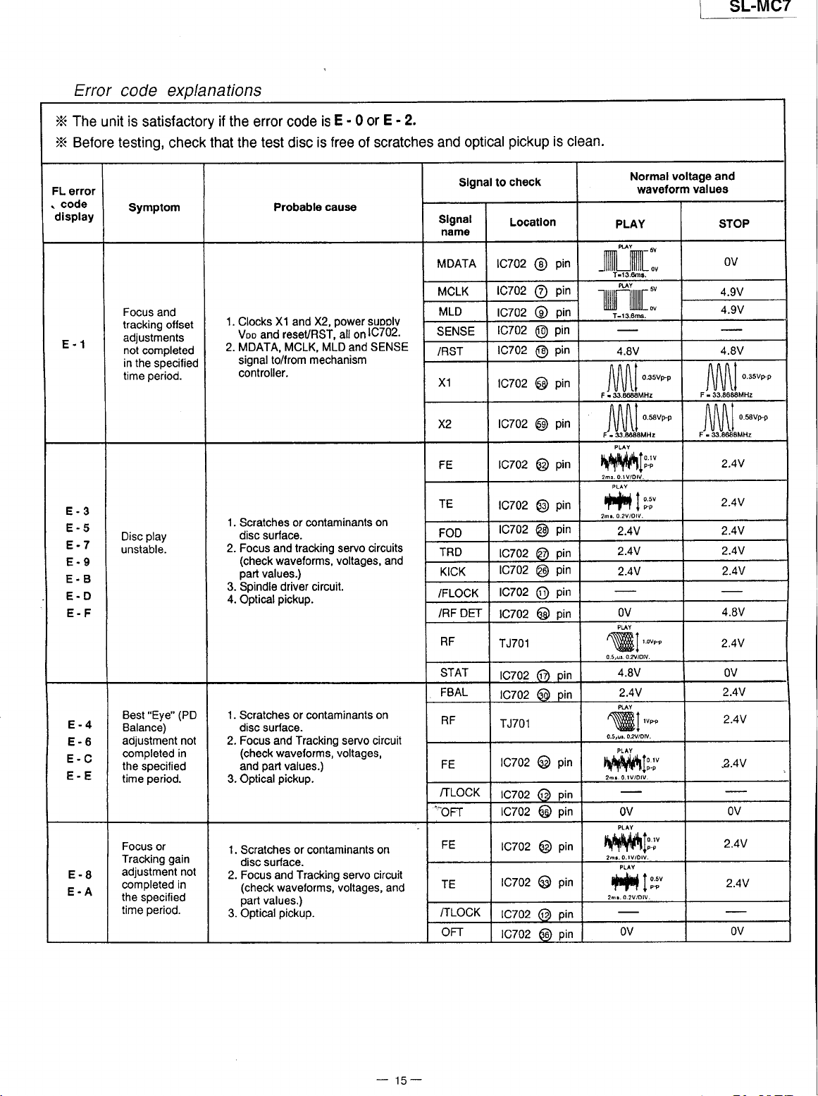
Error
X The
X
Before testing,
FL
error
code
.
display
E.1
code explanations
unit
is
sat¡sfactory
check
Symptom
Focus
and
tracking ofset
adjustments
not
completed
in the
specified
period.
t¡me
if the error
that
the
1.
Clocks
Voo
2. MDATA, MCLK,
signal to/from
controller.
code
test
disc
Probable
X1
reseURST,
and
¡s
free
is
cause
)€,
and
MLD
mechanism
-
0 or
E - 2.
E
of scratches
power
suoolv
1C702.
¿ll e¡
SENSE
and
and optical
Slgnal lo
Slgnal
namo
MDATA 1C702
MCLK
MLD
SENSE
iBST
X1
x2
FE
pickup
chec¡(
Locatlon
1C702
1C702
rc702
1C702
1C702
1C702
1C702
is clean.
pin
@
pin
@
pin
@
p¡n
@
pin
@
pin
@
pin
@
pin
@
voltage and
Normal
PLAY
4.8V
nnnt
l\l\l\l
JlJU\I
waveform
o.3svm
values
,lAl[ff*'
l r.6 ¡ld-t",flñtfff,1''''
1l
IUl
STOP
OV
4.9V
4.9V
4.8V
f\f\flt
J\J\J\.l'"*'
flf\nl
l\l\l\lo*upp
JUVII
2.4V
E-3
E-5
E-7
E.9
E.B
E.D
E-F
E-4
E-6
E-C
E.E
E-8
E.A
play
Disc
unstable.
"Eye"
Best
Balance)
ad¡ustment not
completed
the
time
Focus
Tracking
adjustment
completed in
the
time
(PD
in
specified
period.
or
gain
not
specified
period.
1. Scratches or c¡ntam¡nants
disc surface.
2. Focus and tracking servo circuits
(check
waveforms, voltages, and
part
values.)
3. Spindle driver circuit.
4.
1.
2. Focus and Tracking servo circuil
3. Optical
1.
2. Focus and Tracking servo circuit
3. Optical
pickup.
Optical
Scratches or contam¡nants
disc surlace.
(check
wavelotms, voltages,
part
and
Scratches or contaminants on
d¡sc surface.
(check
part
values.)
pickup.
waveforms, voltages, and
values.)
pickup.
on
on
TE
FOD
TRD
KICK
/FLOCK
DET
/RF
RF
STAT
FBAL
RF
FE
/TLOCK
'¡Fr
FE
IE
/TLOCK
OFT
1C702
1C702
1c702
1C702
1C702
1C702
TJ7O1
1C702
1C702
TJ7O1
1C702
rczo2
1c702
1C702
1C702
1C702
1C702
pin
@
pin
@
6ñ oin
pin
@
pin
@
pin OV
@
pin
6)
6d oin
pin
@
pin
6)
pin
@
pin
@
pin
@
6D oin
pin
6o)
#lrt
2.4V
2.4V
2.4V
\ü{9¡
4.8V
2.4V
añ\\Ytfr!T _..
wl--
0.5,u¡.040v.
h[hJ¡||to.rv
'TT'!F't
t-.^
OV
#t,*
2h¡.0.2VlOlV.
OV
2.4V
2.4V
2.4V
4.BV
2.4V
OV
2.4V
2.4V
2.4V
OV
2.4V
2.4V
OV
-
15-
Page 16

SL.MC7
l
E
Operation
,,ATTENTION
This section
1.
replacing
2. For
Special
3. Select
the main
reassembly
reassembly
items
4. For details
o
Contents
"
Checl<ing
Warning
ACHTUI{G
1,
Checking
Procedure
1. Checking
2. Checking
3. Checking
Checks
SERVICER"
describes
components.
after operation
from the following
disassembly,
This
.
Die Lasereinheit
.
Die
Procedure
Some
procedures
procedures
please
For Each
Procedure
Procedure
Procedure
product
uses
Lasereinheit
For
chassis
components
for checking
replacement,
checks
or
are described
when checks
index
to SL-MC4l0
refer
P.C.B.
Major
Panel
Front
For
For Main
For Servo
a laser
Front
P'C'B'
P.C.8...........
diode.
n¡cht zerlegen.
nur
darf
Panel
the operation
only
P'C.B.
and
Refer
gegen
eine
P.C.B.
have
may
reverse
required.
when
replacement
or
series.
P.C.B..".'""'
Power
to caution
Hertsteller
vom
edges.
sharp
the maior
of
respective
the
required'
are
statement
spezifizierte
Be careful
printed circuit
procedures'
page
on
3'
Einheit
disassembling
when
boards
ausgetauscht
and
werden.
and
"""
"""
servicing'
page
-
17
16
18
"""'
-
22
19
@
@*+
ffi
@'z
o
@
Frame
@
Remove
direction
cabinet
the top
of arrow.
SNE2129-3
I
IXTBS3+8JFZ1]
XTB3+8JFZ
I
in the
(Black)
]
(Black)
]
(Black)
P.C.B.
Servo
(Solder
Side)
@
Pull down
the
fronl
Panel.
Page 17
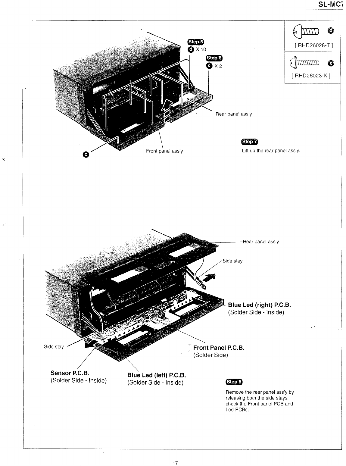
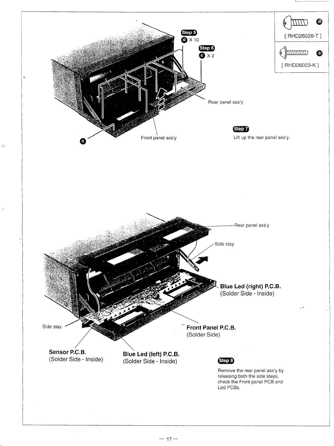
LSryel
Front
panel
ass'y
@
@xro
@
G)
x.
Rear
panel
ass'y
@
Lift up the rear
panel
llmTn
\J-
IRHp26028-T
,-{\
\J¡IN
FHD26023-K
I
ass'y.
(
@
rl
(
@
]
Sensor P.C.B.
(Solder
Side - Inside)
Blue
Led
(Solder
Side
(left)
-
Inside)
P.C.B.
Rear
Blue Led
(Solder
Front PanelP.C.B.
(Solder
Side)
@
Remove the rear
releasing both
check the Front
Led PCBs.
panel
ass'y
(ríght)
Side - lnside)
panel
side stays,
the
panel
P.C.B.
ass'y by
PCB and
-
17-
Page 18
Front
panel
ass'y
@
@xro
@
G)xz
Rear
panel
ass'y
@
Lift up the rear
panel
flrTn @
\J-
RHD26028-T
I
q//*
RHD26023
I
ass'y
-Kl
]
@
Sensor P.C.B.
(Solder
Side - Inside)
Blue
Led
(Solder
Side
(left)
-
Inside)
P.C.B.
Blue Led
(Solder
'-
Front PanelP.C.B.
(Solder
Side)
@
Remove the rear
releasing both the side stays,
check the Front
Led
Rear
PCBs.
panel
(right)
Side
panel
ass'y
P.C.B.
-
lnside)
panel
PCB and
ass'y
by
-
17-
Page 19

SL-MC7
I
2.
Checking
Procedure
For Main
P.C.B.
and
power p.C.B.
tso,u
Power
(Component
P.C.B
Rear
@
side)
panel
@
Remnve lhc reer nangl.
@
Release the P.C.B
from
the Main P.C.B.
(Pinch
the
supports with
below.)
claws of P.C.B.
pljer
suppons
as shown
@
XTB3+8JFZ
I
o
1l
Main P.C.B
(Component
side)
Power P.C.B
(Component
side)
T.U, D.
Support
Page 20

sL-MC7
L
3. Checking
Procedure
€ffiD
Unlock the loading
moving the front lock
manually in
arrow.
Servo
(Solder
the direction of
Front lock
P.C.B
side)
Motor P.C.B
(Solder
unit by
gear
side)
For Servo P.C.B.
gear
Load¡ng
Main P.G.B
(Component
un¡t
side)
XTWS3+10T
I
@@
Move the
in the
(Move
right direction beyond
center of
loading unit manually
right
direction.
loading unit to the
the
the frame.)
]
the
@
Remove
plate.
ffi
\)\
Earth
a
upper rail and earth
plate
Photo Transostor
(Solder
side)
(2)
P.C.B
@
@
Upper rail
o
o
@D
(O
*¿.
*+
-
19
-
Page 21

SL-n/ieZ
__-.-_-----''.---_-----_-,
i
--J
@
Remove
the
guard
rope
Roller
Loading
unit
Main
P.C.B
(Component
side)
@
Rotate
the
wise
with
feed
Remove
Note:
(When
avoid
install
positioned
lifting
lever
under
the
reassembling
the
front
the
loading
loadíng
the
the
loading
feed
under
stocker.)
unrt
to
stocker
stocker.
unit
from
the loading
lever
from
unit
because
clockwise
and
then,
frame.
unit,
the
stocker
the front
Mech
holder
or
counterclock_
slide
the front
make
sure
and
then,
feed
lever
FFC
to
is
Photo
Transistor
(Solder
side)
FFC
(1)
p.C.B
-20_
Remove
Remove
Then,
reconnect
through
the
the
the
mech
FFC
FFC
from
the
opening
holoer.
loading
FFC
to
the loading
of frame.
unit.
unit
Page 22

SL-MC7
1
€@
Remove
@
screw
qfrE
Remove
Sñ-*
IXTWS3+1
the feed lever
@
XTB26+1
I
spring.
@
2J)
@
0Tl
Photo
Transistor (1)
(Solder
side)
P.C.B
@
@'s
qE@
Tilt the
with
the direction
clamp
plate
of arrow.
backward
-
21-
Remove
the disc
guide
(R)
Page 23

_l
@
Release
remove
the
the
2
claws
disc
and then.
guide
(L).
Return
lever
gujde
(L)
c
Temporary
\--claw
A
fix
>-4^erever
ffi
Feedsub r"*rM
Front
lever
feed
@
In case
as
Rotate
Rotate
Or ratate w¡th
Rotate
Rotate
of confirmation
shown left.
clockwise : Loading
counterclockwise
2 mm
clockwise
counlerclockwise
: Unloading
i
manually,
operat¡on.
: Unloading
hexagonal
operation.
: Loading
rotate
operation
wrench.
operation
the
pulley
Servo P.C.B
(Component
side)
-22-
Reduction gear
Page 24

SL-MC7
I
I Type
BA4558FDXE2
AT24C64
AN8837SBE1
AN878ONSBE2
RVDl
SS1 33TA
1
SS291TA
MA165TA
lllustration
RCDGPl
RL1 N4003N02
of lCs,
8A6247N
U28XD
Transistors
and
UPD7BO43FO45
MN662741 RPA
%'r6G036
25B1238QRTV2
2SB132OAQRTA
25D1 8620TV2
Diodes
(100Pin)
(B0Pin)
(B0Pin)
MTZJgRl BTA
MTZJ6R2CTA
MTZJsRlBTA
MTZJTB5CTA
MTZJ3ROBTA
MTZJ36ATA
RVTDTCll4YST
RVTDTA.Il4TST
RVTDTAIl4YST
RVTDTCl24EST
RVTDTAl24EST
2SC3311AIQST
25D145OSTA
2SC2785FETA
BR3433S
LNG995PFBOA1
e-$ac"
DTCl 1 4YKA1 46
2SA1O37AKSTX
2SD21 36PQRTA
LN66S
RSQGPl
S53V
a
frwl
[at_ff
"u
'
'
olllf
-Ca
^-EJL.
I
Terminal
'
1C703 (AN8780NSBE2)
rPin
No,
1
2
o
A
5
6
7
I PGNDl
10
11
13
14
Mark
/RST
NC
tN2
PC2
NC
tN1
PVccl
NC
D1D1+
D2-
D2+
D3-
Function
'c
r/o
Not used,
Not
Motor
Turntable
Not
Motor
Driver
Driver
Not
o
Motor
o Motor
o Motor
o Motor
o
Motor driver
PT4810F
Of lC's
: Focus
used
driver
used
driver
power
GND terminal
used, connected
driver
driver
driver
driver
Coil /
Funct¡on
open
(2)
¡nput
motor
dr¡ve signal
(1)
input
supply terminal
(1)
output terminal
(1)
output
(2)
output
(2)
output terminal
(3)
output
PT48OF
Tracking
("L":
(1)
to GND
terminal
terminal
terminal
(1)
ON)
(-)
(+)
(-)
(+)
(-)
GL4BOV
PT48OF
PT481
OF
Coil / Traverse
Pin No. Mark
u3+
to
t'l
18
19
20 PVcc2
él
23 tN4
24 rN3
26
o4-
D4+
NC
PGND2
vcc
VREF
RSTIN
NC
Motor
/ Spindle Motor Drive
vo Function
o Motor driver
o Motor driver
o Motor
driver
Not used,
Driver
GND terminal 12)
power
Driver
Power
supply terminal
Reference
Motor
driver
Motor
driver
Beset
terminal
Not
used, connected to
(3)
output termihal
(4)
output
(4)
output terminal
open
(2)
supply
voltage input
(4)
input
(3)
input
(Not
used, connected
(+)
terminal
(-)
(+)
terminal
to GND)
GND
-
23-
Page 25

SL.MC7
c
IC701
Pir
Pin
No.
2
3
5
6
7
8
I
10
tl
12
IJ
14
o
lC7O2 (MN662741
Pin
No.
1
2
3
4
5
6
7
B
I
r0
11-l-
12
IJ
i
IJ
to
17
1B
19
20
21
23
¿q
)8, trr\e
i
I
(AN8S37SBE1):
Mark
PDE
PDF
vcc
PDA
PDB
RFIN
CSBRT
ntr^
BDO
LDON
GND
Mark
BCLK
,
LRCK
SRDATA
DVool
DVSSl
MCLK
i
MDATA
IVILD
SENSE
I
/FLOC|
/TLOCK
BLKCK
SQCK
SUBO
DMUTE
, STAT
/RST
SMCK
PI\¡CK
TRV
TVD
PC-
ECM
LPD
LD
RF
TX
t/o
o Laser
o
o Dropout
vo
o
o
o
^
o
o
o
o
o
o
o Traverse
n
o
o
o Turntable
Servo
Funct¡on
Tracking
signal
input
Tracking
signal
input
Power
supply
terminal
Focus
signal
input
Focus
signal
¡nput
Laser
PD
signal
power
auto
conlrol
RF
amp
term¡nal
AGC
input
terminal
OFTR
capacitor
HPF-AMP
LD
APC
GND
terminal
RpA):
Serial
UR discriminating
Serial
data
Power
(digital
GND
Digital
Command
Command
Command
Sense
PosAD,
Optical
(Not
used,
Optical
(Nol
used,
Sub-code
Sub-code
Sub-code
Muting
GND)
Stalus
signal
Reset
signal
System
Frequency
(16.9344
OSC
open)
Traverse
Turntable
Turntable
connection
capac¡tor
detection
ON/OFF ("H":
control
Servo
bit clock
output
(d¡gitat
supply
circuit)
audio ¡nterface
clock
signal
data
signal
|oad
signal
signal
output
(Not
sFG)
used,
servo
conOition
open)
servo
condition (track¡ng)
open)
block
clock
register
Q
data
Q
input ("H":
clock
drive
1cnc,
("1":
(f=4.2336
division
servo
signal
motor
motor
motor
Mute)
cuE,cLVS,TTSropFcLV,secK)
reset)
MHz)
conlrol
drive
drive
drive
Amp.
terminal 1 (E
output
ON,
(E
2
ch)
ch)
terminal
terminal
"1":
OFF)
terminal
terminal 1 (A
terminal 2 (B
connect¡on
Processor
Function
signal
oulpul
circuit)
terminal
terminal
signal
("1,':
LOAD)
lorrresr-,
clock
r,lACEND,
open)
fiocug
¡L':
=751zl
(f
clock
(Not
used,
MHz) (Not
(f=1/192
signal
=
69 2 KHz) (Not
(',1':
s¡gnal
signal
signal (Servo
ON)
(Forced
ch)
ch)
i Digital
NAJEND,
t_eaO-r¡
(,,1":
Lead-in)
connecred
to
used,open)
Crystal
used,
mode)
error
signal)
Pin
No
t3
to
'17
1B
19
20
21
22
23
24
¿c
26
27
28
Signal
Pin No.
26
27
28
29
30
31
32
33
34
35
36
37
?R
39
40
41
.
-
44
45
46
47
48
49
50
51
52
53
54
Mark
/RFDET
CROSS
OFTR
VDET
vo
^
o Tracking
o
ENV
ENVOFF I
TEBPF
TEN I
o Oscillation
TEOUT
FEOUT
FEN
VREF
o
o Reference
TBAL
FBAL
Processor
Mark
KICK
TRD
FOD
VHEF
FBAL
TBAL
I Focus
/ Digital
vo
o Kick pulse
n
I
FE
TE
RFENV
VDET
OFT
TRCBS
/BFDET
BDO
LDON
TES
PLAY
WVEL
ARF
IREF
DRF
DSLF
PLLF
VCOF
AVDD2
o
vo
vo PLL
vo
AVss2
EFM
PCK
PDO
o EFM
o
ñ
Function
RF
det.
signal output
error
zero
cross output
Off track
detection ("H":
Oscillation
Envelope
Not used,
Tracking
Tracking
Focus
Focusing
Tracking balance
det. signal
s¡gnal
output term¡nal
connected
detect inout terminal
error
signal
error
signal
error signal
error
signal
voltage
output
adj.
balance
adj. inpul
Filter
I DlAConverter
Function
outpul
Tracking
drive
signal
Focus
drive
D/A
drive output
TRD,FOD,FBAL,
term¡nal
Focus
balance
Tracking
Focus
enor signal
Tracking
RF
envelope
Oscillation
Off track
Track
cross signal
RF detect¡on
Dropout
power
Laser
Tracking
Play
signal
Double
(Not
used,
Hl-
s¡gnal
Reference
DSL
bias lerminal (Not
DSL
loop filter
loop
VCO loop
Power
supply
(analog
GND
signal
PLL
extract
open)
Phase
compared
(Not
used,
(TVD,
TBAL)
adiustment
balance adjustment
(analog
enor
signal
signal
detection
("H":
siqnal
input
signal
detect¡on
velocity
signal input
control
error
shunt
("H": ptay)
status
open)
¡nput
currenl
¡nput
terminal
filter
terminal
f¡lter
terminal
(analog
circujt)
(Not
used,
clock (f=4.321
signal
open)
("L":
terminal
det.)
('H":
det.)
power
to
terminal
input
output
ECS,
normal
outoul
output
input)
(analog
input)
signal ("H";
off track)
("t-":
detection)
("H":
ON)
"H":dropoul)
(
output
(Not
used, open)
("H":
s¡gnal
used,
open)
circuit)
term¡nal
terminal
open)
BMHz)
of
EFM
det.)
supply
voltage
detection)
("H,,r
dropout)
Double)
2
(Not
used,
pCK
and
inpuj
-24-
Page 26

SL.MC7
Pin
No.
55
56
57
5B
59
ol
162
63
65
66
67
6B
'69
.
1C401
lrro. Mark
ip¡n
B
9
10
A
q
11
t\)
14
t3
to
17
18
19
20
¿l
22
23
24
25
26
27
28
i30
JI
32
33
34
35
36
Mark
SUBC
SBCK
Vss
X1
Voo
BYTCK
/CLDCK
FCLK
IPFLAG
FLAG
CLVS
CRC
DEMPH
RESY
vo
o
Sub-code ser¡al óritnilt cln^k
9ub-code
GND terminal
Crystal
o
Crvstal
Power
Byte
n
o
o
o Flao
n
U
o
clock
Subcode
(f =CLDCK=7.35KH2:
Crystal
Interpolation
terminal lNol used nnon\
Turntable
"L":
CLV,
Sub-code
"L":
NG) lNot used nnenl
De-emphasis
used.
oDen)
Re-synchoronizing
(Not
used,
(UPD78043F045)
vo
VSS
VDD
SBCK
NC
SUBC
VTUÜ
DMUTE
SOCK
NC
SUBO
/RESET
OPREQ2
OPDTIO
AVSS
OPCLK
OPREQl
DIR
SLIDE
LOAD
BSTSV
MODEL
VSS
AVDD
AVREF
XT1
XT2
VSS
X1
x2
MCLK
I
I
o
o
o
t/o
o
o
r'\
Connected
Power
Sub-code
Nol
connected
Sub-code
Chip
select
Mut¡ng
Sub-code
Not
connected
Sub-code
Reset
signal
Request
Data
signal
GND
terminal
Clock
signal
Request
Motor
Motor
control
Motor
control
Beset
s¡gnal
Connect
Connect
Power
Power
(Not
used,
Not
used,
Not
used,
GND
terminal
Crystal
Crystal
Command
Function
serial
input
data
osc¡llator
oscillator
supolv
terminal
siqnal
frame
clock
frame
clock lNot useri onpn)
flao
phase
servo
Rouqh
servo)
CRC
check
ON
open)
Micro
Function
to GND
supply
term¡nal
serial
serial
terminal
control
signal
register
Q
Q data
output
s¡gnal
inpuvoutput
output
signal
control
signal
signal
signal
(f=16.9344MH2,|
term¡nal
(f=
terminal
(Not
Normai)
terminal
signat
16.9344MH2)
used. ooen)
signal
synchro
lNot used. onen\
terminal
("H":
ON)
signal
of frame
Compurer
input
data
input
clock
clock
2
output
1
output
output
to
GND
to
GND
supply
term¡nal
supply
term¡nal
connected
connected
open
Osc
terminal (F=4.2336MH2)
Osc
term¡nal (F=4.2336
clock
to
signal
to
GND)
GND
signal (,,H":
(,,H,,:
OK.
(Not
sync.
MHz)
Pin
37
38
39-42
+J
44
45
+o
47
4B
49-5
52
53
54-55
56
57
5B
59
60
62
63
b4
65
66
67
68
69-70
71
72-80
No.
1
Mark
MDATA
MLD
VSS
PWN
CLDCK
POSITION
SPEED
BLKCK
rc
VSS
VDD
POWER
VSS
SINGLE
DISC
MLOCK
CLAMP
FREE
PHSELl
STAT
REST
PHSEL2
TESTl
TEST2
MOSEL
LED3
\/aa
VPP
VSS
Reset
Polarity
signal
Frequency
vo
Command
o
Command
connected
o
Motor
LD
Rotary
Loading
sub-code
Not
Connecled
Power
Power
Connected
Disc
Disc
Mechanism
I
Mechanism
I
Mechanism
Connected
Status
TTSTOP,
Rest
Connected
Not
Not
Connecred
o Disc
Connected
I
Power
(Not
Connected
terminal
after
direct¡on,
(Not
used,
control
data
load
to
GND
control
signal
power
det.
position
tray
motor
block
used,
connected
to GND
supply
ON/OFF
to GND
slot det.
lerminal
control
signal
det. terminal (S501)
det.
det.
to
GND
srgnal (CRC,
FCLV,
position
used,
used,
det.
used,
det.
to
connected
connected
to
signal
to
GND
supply
terminal
connected
to GND
GND
GND
"MASH"
control
terminal
connected
terminal
Function
signal
("L'
signal
terminal
det. terminal
speed
sensor
clock
to
terminal
output
terminal
for
sinqle
(S5OZ)
terminal
(5503)
terminal
CUE,
QCK
to GND
to
to
circujt
power
to
of crystal
LOAD)
signal
GND
CLVS,
GND
G
of
(Nor
RF
-
25-
Page 27

SL-MC7
Wiring
I
i
Connection
|;diñ]
eowen
[!
Diagram
SUPPLY
P.c.B
runrru
I
enorornANsrsroR
ll
P.C.B
e.c.a
(2)
OPTICAL P]CKUP
senvo e.c.e
I
(\
\\[^,^,
,0,
Y9)-
M702
SPINDLE
/
Moron
I
\o /
oercal
flil
O
\
o
)
e.c.e
E
F'Jr'-l
fN503
cN501
l¡o t'
r'l
I
l:;l
tl
enorornANsrsroR
B
P.C.B
(1)
LI
elue LED
It
P.C.B
;..
Componenl Side
seruson e.c.e
fl
(Let)
|Jl
El
uoron e.c.e
I
.-*;
I
p
swrrcH
P.C.B
erue leo
@
(Risht)
P.C.B
Page 28

SL-MC7
Block
f,
Diagram
[e701]
OPTICAL
I
I
I
I
I
I
I
I
I
I
I
f
I
Semiconductor
I
I
I
I
I
I
I
¡
I
I
I
t
t
I
I
I
I
r
I
I
L-______
I
I
I
t
I
I
I
I
I
I
I
I
I
I
I
I
I
I
I
I
I
I
I
I
I
I
Focus
¡
coll
I
I
Tracking
I
coil
I
L
TRAVERSE
M701
MOTOF
PICKUP
Tr
ll
II
laser
It
tt
tl
'l
I
I
I
I
t
I
I
I
I
I
I
I
I
I
¡
ANBTSONSBE2
FOCUS
cott/tRnvERsE
/ splt¡oue Moron
COIL
AN8837SBE1
lrc703l
/TRACKING
MoroR
SERVO
DRtvEF
AMP
----_l
Fleser
I
INFESET | ,
ln"'"ni""L,¡-;
VAtrtr lu
rN3
oa\ | 1)
I
l4
CEA
-t
'IENV
l- l'v
/RFDET
l.^
t5nroEl
i
ENv
M702
SPINDLE
MOTOR
14
?14
GND
PGNDl
oc*oz
-27-
Page 29

pL-¡v¡ur
_
i
Ic?'ot
SERVO
PBOCESSOR
MN662741
DIGITAL FILTEB
RPA
/ DIGITAL
D/A
/
SIGNAL PROCESSOR
CONVERTER
/
BOo
47
u
a
o
39
Synchron¡zing
inlerpolaiion
prolectron
4l
501
6
x6 R
:
€: i
721
60
2
1
3
62
D/A
convener I Servo
I
outpul
pon
OO
óo
16
--t
o
:f
|
ói 5É
86'9á
ttcrol-l
uPD78043F045
MfCRO
COMPUTEB
c
G
-o
63
20
52
x701
(16
9344MHz)
O
o
)
l-s-)
{
Y
I
4l
-CF-
O
o
0
-28-
Page 30

lrc801l
BA455SFDXE2
'"'l
sl-rvrcz
I
@(9
[ed-o]l
8A4558FDXE2
l-rci=6il
BA6247N
MOTOR
DRIVE
(LOADTNG
ro
"*l
M50r
MOTOR)
''*'ou'
|
131
'.ó
u
ts
l
43
'{
1
-
q
23
(POSITION
-T-r
_48_4E__-ó_4
SENSOR)
x40l
(4.91Mflz)
r-1'------r
l¿¿
ltnr I
t-lui-l 11*-1*-1
t'-'trttl
rr+tl
Y+frl
r
ssl
l
ool osl ztl
f;ñÉ
I!Uñ
FF=
s<l
[e¡oit
uPD78043F045
MICRO
COMPUTER
J?,l'd^^"r,1]
,o,r.
(SPEED
SENSOF)
(DrSC
SENSOB)
OPREQ2
OPCLK
OPDT¡O
aJ
';t--^-
+Y
Hn¡rt
I "^.,+
-""@
ou"l,
V) ftl
1-i
-
29-
Page 31

-
pL-tv¡ur
I
-
-
- -
ñoiei
f
rl
=)r
i
i_
CD stgne¡ t¡ne
? 1
_t1"1':,l"Ir1y._Rlgl
- -'r
:n:"¡'l
I
_i
c9
€D
016
15
Q15,D
roruorsnuv
(Fr6or)
l:
L
RCDGPl
REMOTE
U28XD
SENSOR
rnEor
IRE02
TSCK
rsr
rso
-l
llC602l I e ^
l¡z¿ce-c
vDD
?--{rt
(4.91MH2)
[-r-1
T T-
rl
ltnr I
r-1un
tl
Yf
t!2
o
t
ts
=o
I
ñ
G
@F\t
zz^x
v>
>
vvvE
óo
*3.
uU
>.
v>
U
u
t.¡e60'it
UPD780T6GO36
U-COM
9¡r
vo
o
<-\-o_
86
T-l
-
r00
-L-:f
_ ----{--\_!_
49-78
r--"1
:
_
8o-8s
-30-
Page 32

SL.MC7
I
Troubleshooting
.9
E
r
Guide
og
oó
<E
Pb
v 6:
-0:F
co
ü
>q-
o9
o
lqo
.tse
5o
9\cY
\o
€o
39
9a
9o
=
¡ R¡
J
:*
9
hc.9
stb
'ñ\
=o
o/6.\
F\ry/
->
aci
:-;
É6ó
o
=
O
-
-9
o
x x.:
o
AJ
d--
E
:
N
O
_:
ots
!¿o
ó.
-31 -
O
f,
o
¡*;
o{i
i:!
oF¿
ló;
o/
c
é
YY<
JOU
OGC
@)A
(6lo
'dO
/a
6
o\
ñ;
=Y
|
/
/
3
N
N
o
o
z
o!'
::9
: x;
{:
|-\
t)
/l'
\l
Page 33

SL-MC7
i
Scnemat¡c
I
cD
tr
tr
E
E!
E
tr
G
(All
sERVo
FRoNT
sLtDE
pHoro
swtrcH
eANEL
MoroR
rRANStsroR(l)
ctRcutr
sENsoR
BLrr€
LED
schematic
diagrams
ctRculr
Note:
.
s501
.
ss02
.
s503
.
s601
.
5602
.
5603
.
s604
o
bbu5
.
s606
.
¡bu/
.
5608
.
s609
.
s610
.s611
.
5612
.
s613
.
s614
.
s615
Diagram
ctRcutr....
ctRcutr
ctBcutr
(Right)
: Lock
:
: Clamp
: Single
: lD
:
: Programing
:
:
:
: Numeric
: Numeric
: Numeric
:
: Numeric
:
:
:
ctncutr
may
det.
Clamp
det,
det.
play
scan
switch
Random
Numeric
Numeric
Numeric
Numeric
Numeric
DISC
/
CAPS
Numeric
be
switch
switch
switch
(SINGLE
Mode
(PROGRAM)
/
Character
/
Character
/ Character
/
Character
/ Character
/
Character
/ Character
/ Character
/ Character
select switch
/ Character
Page
.......38
-
-
....36
39
37
............33
ctRcutr...............33
.......................37
......................37
.......s7
modified
(
MLOCK
(
switch
at
)
CLAMP
(
)
FREE
)
>)
switch
switch
select
switch l
select
switch
select
switch
select
switch 4
select switch
select
switch
select
sw¡tch 7
select
switch 8
select switch
select
switch
any
2
3
5
6
g
0
time with
the development
BLUE
tr
MOTOR
E
MAtN
II
PHOTO
K
POWER
E
oPTtcAL CrRCUtT....
M
of
.
s616
.
s617
.
561B
.s619
.
s620
.
s621
.
s622
.
s623
.
s624
.
s625
.
s626
.
5627
.
s628
.
5629
.
s630
.
s631
.
s632
.
s701
(Left)
LED
C|RCUTT
CTRCUtT .......................................
TRANSTSTOR(2)
SUPPLY CIRCUIT....
new
technology)
:
Numeric / Character
: Text edit
: Text mode (TEST
: TexVCharacter
: TexVOharacter
Disc
:
enter
: Disc
skip
:
Disc skip
:
Search
: Search character >>
: Stop
:
: Skip/Cursor
: Sk¡p/Cursor >>l
: Play switch
: Power
:
: Rest
character
(I
(
Pause
switch
CD open/close
detection
C¡RCUIT
(TEXT
EDIT) switch
MODE)
Search
Search up switch
(DISC
ENTER)
(-)
(+)
<<
switch
)
switch
ll
)
l<<
sw¡tch
switch
CtRCUlr
..................33
select
switch
switch
down switch
switch
Page
.........37
.....33
-
34
35
...............
35
.....33
>=10
.
Signal
line
Ihe vollage
osc¡lloscope
Accordingly,
measuring
.
lmportance
Components
of
be
Caution
lC,
Secondary
unit.
fire-retardant
sure
to use
!
LSI
and VLSI
.
Cover
.
Ground
.
Do not
.
Put
value
and waveforms
on the
basis
there
may
arise some
safety
notice:
identified
trouble
the
a conductive
by
(resistors),
onry
manufacturer's
are
sensitive
can
be
parts
the
soldering
touch
the
+B
Line
of
chassis.
mark
A
high-quality
to
prevented
boxes
made
iron.
pins
of lC, LSI
mat
on
are the
error
in voltage
have
spec¡al
specified
static
electricitv.
by taking
plastics
of
or
the work
reference
values
No
Mark
characteristics
(capacitors),
sound
parts
cáre
with
VLSI
with f¡ngers
table.
-BLine
:
voltage
of this
and
waveforms
:
CD stop
important
shown
during repair.
low-noise
in
the
aluminium
directly.
foil.
unit measured
depending
for
safety. Furthermore,
(resistors),
parts
r¡st.
:.>
l:.:.1.1
by
DC electronic
upon
the internal
etc.
are used. When
:
CD Sional Line
voltmeter (high
impedance
spec¡al
impedance)
of the
parts
wh¡ch have
reptac¡ng
tester or the
purposes
any
of components,
and
-32-
Page 34

SL.MC7
SCHEMATIC
DIAGRAM.l
tu:+8UNE
I
II
¡'rxg"i.'i'lh'
tllll),
ofJ!"uo!' r
,OE
nx
ctRcur
(cN4O2)
Oil
SCHB¡ATIC
cMv-2
Dt
co slcMl
uÑE
JKAOl
RCH
.""
--l
LINE
our
A
JKI I
rcN
2JOr'-210V
50B¡
I
MOTOR
P.C.Boord
CIRCUIT
poge
on
46
)
;lñlslfil3
OPTICAL CIRCUIT
(
P.C.Boord on
poge
45
0522
PT480F
POSmON
SEMSoR
PHOTO
CIRCUIT
(
P.C.Boord
050,r
25813
D6C
DEEm
TR.( 1 )
on
poge
46
)
SLIDE MOTOR
CIRCUIT
(
P.C.Boord
on
poge
-
46
33-
\_r
c541 C542
)
on BMr&
ll0.0l l8Vl0
Page 35

SL-MC7
i
SCHEMATIC
MAIN
DIAGRAM_2
-
CIRCUIT
+0
t
uf¿E _ _ _
(
P.c.Boord
on
PIlsEU
REST
sf^l
Pt6€Lt
f¡€E
curp
vtocx
DSC
9llct¡
-8
:
poee
uN€
40
gcML
,
co
E:l>
uxr
)
,OE
moM
PA}€L
ctRclJrI
(0{60r)
0x
tfttHR
9 s?
C K L I¡N
É I o
O P
Q
g
o
R S I2 U V
W x
-34-
,oll
YOTfi
CIrcUÍ
(cx5ol)
EftffiL"'
;E
mlF.,,r
(FC4OJ)
o.{
fr
s[Hsg
Page 36

SCHEMATIC
DIAGRAM_3
--:
+g
uN[
st6Mr Ll€
: cD
ll::\
Ea{}1
BA/ts58FDXE2
A¡¡p
LP.nLEn
PHoro
CIRCUIT
(
P.C.8oord on
rR.(2)
poge
45
)
R85
1
2.2K
ot*lJtr*,
Q851
Q6tr
RVTDTAI24EST 2SD145OSTA
¡\ ^,.
2S812380RW2
REOUI¡IOR
oJ2.OJ3
f
lO@P
T
-
35-
Page 37

SL-MC7
SCHEMATIC
FRONT
DIAGRAM-4
PANEL
.tnfl
FLIOI
RSL0240-F
ft
DiSPIAY
h
I
I
t
I
*-_
CIRCUIT
adcb
ON
------- : -B
PAGE
{2,49)
I D fr n
+g
:
Uf,f
(P.C
BOARD
LJNoFEOCSA
u
fl il
t ailáan
FLSOI
^o-91
ooooo
FOHIJX
oNItr(.,lli0FtDc8A
UNE
¡y¡ry
il fi il
ut rr
*fi ;
; ; ; ; ;
qponñt
k I I h
a;=.2',8
Irútót
vl
I
c
a
¡
f
¡
0
6
u
a
-36-
Page 38

SL.MC7
SCHEMATIC
DIAGRAM-5
-:
+8 tlNE
-------
nm2
AT24C64
€lPROt
-g
|
UNE
Q62r
RWDTCl
I.TD ORI/E
l4YST
2SBI
258QRTV2
t.E) ORI\,E
0651
2SC27E5FETA
R€SEI
@TIROL
_______l
8ln'6r,lED
E
(P.c
BoARD
oN PAGE
SWITCH CIRCUIT
(P.c
BoARD or.J
tr
rcmJ
RCDGP 1 U28XD
REtaoIE SO¡SOR
PoÍER
1C603
(R)
42
)
pnce
+s
)
F,l.#{yff0.-t,u.,
.,
,
-
37-
SENSOR
(P.C
BoARD
ON
CIRCUIT
PAGE
43
)
Page 39

SL.MC7
AOPTICAL
i:
SCHEMATIC
PICKUP
CIRCUIT
DIAGRAM-6
CO SERVO
El
+B LINE
p.c.Board
CIF{CUIT
o;
cGd!
uF>uuF
(
;
¡ ¿ ¿ ó
on
pase
44
)
FB
)--
LZts<AZO
";s333."
Lh9i
OUFG
ó¿¿!F9l
:¡ñ;óüq
lP41
TP12
pÉ
TP39
FÉ
TP¿O
I
¡F$#¡lBr;
1c703
AN878ONSBE2
FOCUS COrU
TRACKING
COIU
TRAVERSE
MOTOR,/
SPINDLE MOTOR DRIVE
3!
A;
;c
g-
ot
dvt4hVhtg-'r
2ms. O. !V/DlV
$r
2nls 0. lV,'DlV
za
zÉ
R725 C7t5
I
2K
R736
rm
F
1BMP
R728
6.8K
,:o?
-l
I
óñ
-38-
Page 40

SL.MC7
SCHEMATIC
DIAGRAM.T
ffi\{rx
I
-=
xB
;:f-l;'f
;!|
rmr5V
11 il
n=z :srrr,"
Voo
x2 AAn r PIAY rÉak1x2
x'
v$
sBcX
suac
PDo
PcK
EFM
AVs2
AVoo2
vcoF
PLLf
DSLF
DRF
|REF
aRF
wvLL
PUY
TES
+B LINE
R7t7
IK
ov
YYXOOoO->SF:-:G
!:: í
*
Y
*
F..tG 93.t4Mtr¡
"
d d
H
¡
=
fl f\ n I
i\i\/\ l¡fy
J
ó
U
{ lll l]I
U t
lCtO2
MN662741RPA
SERVO PROC€SSOR/
DIGITALSIGNAL
(
i: d i
-¡ll{-_lt{_lnt'"
PROCESSOR/
Blf'Já'.iÉIiFi
PL Y
|nnu
ñ
+
\\W$ J¡it
WI
o sus. olv;orv.
r.a >
=^xq. f
z
/v\liir
llllz.ftB pA
1
p33.9e,
B
-
PUY
lll lll lll
T-
ll 3n's
.
\:.
Púl
fl ll
J{ _JLov
l-75llz
/
*l,lu
nu
\--rcur
\t-ruo¡rr
L>
/+BtfCK
/
.u
o
5E
\
.
BCU(
r_RcK
SRDATA
Dvool
ovst
rx
Mr¡
SENSE
/FLocK
fiLocK
socK
SUao
DMUrE
srar
'Rsr
SMCK
PMCK
EBEEESEguÉEgNE!$ÉxEE
f*r-l-'f--tltttl
,l L-.lJJ ov
0.1rs
2VlDlV.
ltf-ltrsv
ilt ltl
lll ilJ ov
T= l3 3nrs
5v
o"íói'ovx¡t.o
SWITCHING
4SI
2ms.0.lV/DtV.
g-'Y-5
-
39-
TOII
MOTOR
(cN502)
SCHEMATIC
DIAGRAM
CIRCUIT
ON
-1
xo=x
lz
>;
c753
470P
¿I
-8
702
CN
z
ci
ót
9
Page 41

SL.MC7
Printed
!
Circuit
A
mnnr
U
+g
-o
-lb+,,i-
oo98''"
BOafd
P.c.B.
r_
9:floo¡op-l
t
cNzJ
*g
$a
(Th¡s printed
c?g
il;,^
o.r*--
-*
#
-:
%*_S ilkJu*
-u*A
Llffi:
a@e=;s
¡e¡s
)
q**g
lqlftfi¡
..r{
F+
+E,_,,
c41 1
-{F
,;- ffi
llls
lrlg
llli
li*
I
.
re
ir'ro
Flte"-
d.'*g*+t
*s+s
fil flc
llhrr
llP
U
:
,,o
lH
ol
circuit board
d¡agram may be mod¡fied at any t¡me w¡th the
(REP2491J-M)
REoE REoE
N
+g
r
+g
ila
olÉTffiE*
€i,o*,
*
r'Ji
**,
#
FB-W{
*pGnld
,%lF,\g-
:
J**r
''tlEll'
r-liF
¡ltg
fi]
fil mn:
lil*
-
lll; [ru*+s
lll
l-,Y
JFJ-g''
il'Te
TH
+fi
lÉlñ|fi
fil=
Hil*.#
tll8
':11--%N
|g|a|
sE iL* _ lila
gg
ille
r^ lllsp
ri
ll]*,,
#
I
i
developement of new technorogy.)
o
E
{ d E E
|slf+'@s
|:[-f
'tk
, o
+s
+*i*$=#"
-^
n
(f
íLrLÍ'. [É
ilFilFilj*lE
Hl
s-
---trzm-
-:
xl5F
s' l¡
V.
Srfil
'B
frlllF:E
ilLiltó,;g
llBlll :::q
llPllj
l]1"==ffi
P¿IA /+
lll
l-t
TR
¡zos
*--f,Td]*
'-
f-l
h=l
'l
li¡
Semiconductors
Localions Table
:-'-_--_-
Ref. No i Loc.
r
'ii
cN23 81
cN401
cN4o2
cN404 87
Dl1 I 84
D12
D13 i 84
D14 I ao
D15 D4
D16 E4
D17 C3
D21 A2
D22 " 82
o23 83
D24 I 83
D26 84
D27 C4
D31 S2
D32 82
D33 | A2
D34 I 83
D35 A2
D41
iD42
D43
D51 45
D52
D53 j eo
Ds4 I 46
D461 E4
D801 I F2
DBo2 I F2
FC403 I F3
lc]1 I c4
1c401
1c461
rc801 I D2
Ql1 i
o12
o13
Q15
911 ??
o32
o33 A3
Q41
0461
i
oaor I rz
oB02 I E1
i
oB51 J C3.
r
Q852 C3
I
J
i
I
i
I
lE4
ic3
I
I
F6
E3
84
C4
86
Cs
85
D7
C3
A3
C4
A3
C5
D4
No
|É;
ffi #rf+hlt
lt
Page 42

SL.MC7
powER
tr
supply
\yJ
.1
f6'L*-J
\9
6F_=
\-/
N
l-t-\--1
\-/
(F
p.c.B.
{
1
{
(FEp221BF-p)
z.
o
L!
YA
O<
OL!
:trJ
a
a_z
O
-brF
uzu
F-O
l) rñ
IlJ
JLtl(/)
L-JO_
<-
Z.Lr-l-l-
o:f
FY>O
)u)
<-()o
OOI<F
?*
Jo
cf)
c{
v
:)
Page 43

9I-Mql--_l
rnoNT
f,
FC602
iN
L1J
-n
dlll
;ll
c600 c651
N+ H+
-Tr --ffR651
PANEL
s82e
>>
:::125á
J2g3
p.c.B.
l-7] s828 lTl
b-d
t_J l_t
J251
¡$¡0r
K<
---
pq
Isq
Hlfr'
-^tt
(REp26soE-s)
c602
-ll-
:
,
#::i
DAI'
65t
N+
--1t*
R65J
}'JE
s627
r:l
P_9
PAUSE
:fil
:fil
:fil
-14 ?Ul -!J
b-d
J2JO
ñ61-6'
R6r1
lcl
-=lu:,
W.
¿228
s6241:-l
,,:r
<<p
q
-fll
*fl
-lll
Nlll
-llJ
-l!
s626lTl
srep-d
ll
lffij¡3-ffi-l
rurezscr
I
€J¿zL
¿?26
:TEXT
58201 ' lS8l9lrl
-.¿21!_
SEARCH
.E99li.
R6o7
-
,AL9'Y--P_9
st
+-
.#
Pl
b--dY"Y
ll
I
EtEEt
-qtr
sKrP
0t$
;FHü
t]
t'-d
R6o1
R6o5
R002
n00J
T-:--1 S01 E r--:-l S
p_gffii
-=!H:.=:44+g
J2.18
P3¿
EE
fil
eluE
LED
(REP2680E-S)
(Lert)
P.c.B.
-42-
eluE LED
@
(REP2680E-S)
(Right)
P.c.B.
1'l',
;r
Page 44

-
1s617
i TEXT
lEDrr
l
)
I
t
J217
i:
l:l
Q Q.
,J106:
¿234
s007
>1o
ü,
s609
rrl
PQU
sor
2
r:r
Pq'
s6f 5
E'
m'
s608
E-
s61 I
E,
S01,+
f:l
D Oorsc
I ICAPS
J21 5
;
¿21+
*-f,zrt-
S0O,+
r:l
pq
ll
PROGRAM
c60¡+
;
{F¡zoz
J2oa
R61 I
f:l
P_9
RANDOI¡
:
s803
e621
Sfll
f3l*F¡
au
Lil'lo
r
ID SCAN
Q622
l?l
tt
t¿l
l'/
o
lcl
tt
Q623
q
$lill
J205
Jeo6
s00t
t:l
pq
ll
s [,¡GLE
SL.MC7
ülgl
seruson
El
P.c.B.
(REp26BoE-s)
-
Ae-
Page 45

SL.MC7
i
E
cD
sERVo
p.c.B.
(REpxo144A)
-44-
Page 46

sr--urcz
I
swrrcH
tr
P.c.B.
FC601
F:z.¡l
|-l
(REp26BoE-s)
:1
PHOrO
K
P.C.B.
TRANSTSTOR
(REP2348A-N)
(2)
oPTtcAL
M
p.c.B.
(REp24e1J-M)
OPTICAL
OUT
Page 47

SL-MC7
The
RFKBMC4|1PK
__l
3 P.C.B.'s
shown
'P.C.B.
below (REP2494-1N
ass'y reference
,
no.37d (
REP2494-2N
refer
,
page
REP2494-3N ) are sold as
51 - Repalacement
Parts List
assembly
part
).
no,
PHOrO
J
TRANSISTOR
(1)
P.C.B.
(REP24e4A-2N)
g
sLrDE
MoroR P.c.B.
(REP24e4A-3N)
,,t,
lr
. , \\r
i
Voszr
t-
moron
ll
P.c.B.
(REP24e4A-1N)
--------:Eñr'--
+-:-
Nlll
olll
Nili
-ili
ñli,
oirl
NI
-l1l
qll
.
JSOJ
\
frE
LI
fit
úl
ln
fir
JJOI
cN504
l?sñ:rT1
¡l'
I
l,i
Page 48

sl-ncz
I
f Loading
Mechan¡sm
Parts
325
324
311
308
395
419
lstffi<
ó.*
i C' ¿¿d
..,.üi,.
44(
'*+\
=ñw
325
G
Y 32s
rg
iE
+.-
t
.,qY
lSt*:
b
I
T--;--
)
a
I
¡
JW
306
l-l@l
rl
V ll I
q&l
so'ó-z
I
ái'o
/zE\
-
tl
I
320
050r)
ór502
.t/l,
!-
t
A
325
Note I When changing loading mechanism
apply specilied
"
XX
grease
"
as shown in the drawing.
m
re
to
the areas
parts,
marked
Page 49

SL.MC7
I Cabinet Parts
/^\.
l'\ \
,
1
Ll
336
339
-,',
iir
""'-¿ '
i ---<i
\ .t tr 954
t¿a>3
I
l,
/--!-7
.]."f\'-.-
u;r.
:sz
I
ri
':,
"
l{'
+r
sss
\,r
Location
-ii--t-
\
\t,
ll
L-ll)
l
i
)1
,,i"*¡
/.f
.i)-:..
"..:J
".¿.
_1,,'
329
;{
-48-
Page 50

/1\
-.-7
37
4
Y')
37
a?
37
4q
'il
:;.i
r i- ü
FC6O1
FRONT PANEL P.C.B)
(swtTcH
\P
I
FC6ol
I
41
"4
Pc.B)
-
49-
Page 51

rJl--lU¡ly,
I Replacement
'
Notes:
net ¡lo.
lmportant
Components
Furthermore,
When
.
The
Parts
[N/]
"
Warning
Part
I
No
safety not¡ce
replacing
parenthesized
w¡thout
¡n
Remarks
:
Part
Parts
identified
parts
spec¡al
any
of components,
¡n
the Remarks
these
indicat¡on
co¡umn indicates parts
producl
This
Name
& Description
I
I
-l
I
RK¡/0336-K
r
2
sNE21
29-3
3
RMNO443
5
REEOB6T
BEZO9BB
7
REZ0905-2
8 RGRO247C-CA
B RGRO247C-DA
I
RFKJL¡,4C70P.K
9.1
RKAOO79.A
10
RKJOOl
6
11
RKQOOB9.J
RKQOl
93.K
13
RKQOl
94-K
l4
RMEO2O9
15
R|UN0341
Bt\¡80950-K
17
R¡/R0961
to
Bt\¡xo1
15
RMXOl 16
10
RFKGL¡IC7EB.K
20-1
RGKlO4OB.O
21
RGt041
22
RGL041
23
RFKHLMCOP.K
RGK]041.Q
BHD26023.K
25
RHD26O28.T
26
BKGOOO9
21
RKW0543-0
28
RtuA0998
29
RGPO67O.K
30
RGUl
649-K
31
FGU
1 650.K
32
RGUl
651-K
33
RGU 1
653.K
34
RMGO429.K
35
TB3+1
0FFZ
CABINET
CABINET ACCESSORY
SCREW
FL
HOLDEB
I 4P
FFC
36P FFC
3P FFC
BACK
PANEL
BACK PANEL
BOTTOM
FOOT
SIDE
STAY
PCB
HOLDER
SIDE
GRIL
SIDE
GRIL
STAY
SPRING
FL
HOLDER
FFC
HOLDER
-0
FFC
COVER
MECHA
SPACER
IVECHA
SPACER
FRONT
PANELASS'Y
rL F¡LI TH
4.Q
PRrSM (L)
5-0 PRISM (R)
BACK
PANEL
REAR
WINDOW
SCREW
FRONT
PANEL
IllAGNET
WINDOW
MECHA
ANGLE
GRILL
POWER
BUTTON
i\¡AIN
BUTTON
PROGRAM
12
KEY BUTTON
CUSHION
SCREW
AND
CHASSIS
CHASSIS
(L)
{R)
A
B
ASS'Y
SCREWS
CATCH
BUTTON
RUBBER
:
by
A
which
uses a laser
ASS'Y
IM]
tMl
t¡/l
iN¡]
ttvl
tr\41
l14l
ttvl
tMl
IM]
tMl
IM]
{Ml
t¡/l
t¡/l
IM]
IM]
ttvl
llr4l
ltu4l
tMl
tMl
{Ml
{Ml
{¡/l
tMl
List
mark have
purposes
have
be sure
columns
can be
used for
Flemarks
t¡/
f¡/
tM
l¡/
t¡/
t¡/
ilvlE
EG
lMlEE
tMl
tr\¡l
t¡/l
tMl
special
characterist¡cs
of f¡re-retardant (resistors),
lo use
only manufacturer's
specify
the
areas.
all areas.
that
aÍe supplied
diode.
Rel No
30
XTB3+20JFZ
37 XTBS3+BJFZ1
39
RFKBL¡/lC6P.K
40 SHRDl
41 XTBS26+8J
Rt\4N0203
300 RAEO1522.]V
300-1
SHGDl 13.1
Refer
Part No.
63
by MESA.
to caution
300-2 SNSD3B
301 RMB0455
302 Rl\il10423
303
RN,l10424-1
304 RI/R0937.K
305 RMS0123-1
306 XTN2+6G
307
RMS03s0
308
FMQO653
309
RMRO624.W2
310 R¡/R0926-K1
311 RlvA1003
312
FME0225
313
RHW52002
320
RFKPLMC5OPAK
321
BFKPLI\¡C50PBK
322
REZ091
6
323
RMGO2OO
324 R[¡R0334
325
XT8526+1
0J
326
XTWS3+10Q
327
RDGO333
328
RDGO334
329
BDGO374
330
RMAO904
331 RtvA0905
332
RtuA0914
333
RMAOg1
5
334
RMAO9l
6
important for
safety.
high-quality
specified
(Refer
to the cover
page
on
Part Name
SCREW
SCREW
BLUE LED PCB ASS'Y
CORD
SCREW
PCB HOLDER
TRAVERSE DECK
TRAVERSE
FLOAIING
TRV
I/OTOR ASS'Y
FRONT/BACK
FRONT
BACK
TRV
CHASSIS
FIXED
PCB
FIXED PIN A
¡/AGNET
CLAI\4PER
CLAI\¡P PLATE
BACKYOKE
SPRING
WASHER
LOAD¡NG
SLIDE MOTOR
23P FFC
RUBBER
FIXED
SCREW
SCREW
FRONT
BACK
EOTTOM LOCKGEAR
SIDE PLATE
SIDE PLATE M
TOP
RAIL
BOTTOM
BACK
2.
& DescriptíonRemarks
HOLDER
CUSHION
SCREW
AB[/
SPHING
AF¡/
AR[I
PIN B
SCREW
MOIOR
ASS'Y
ASS'Y
TUBE
PLATE
LOCK GEAR
LOCK GEAR
L
RAIL
SUPPOBT PLATE
sound
parls
shown in the
page
for
ir\¡l
l,4l
iN4l
ltvl
ttr4l
IM]
ttvl
trvll
tMt
IM]
lr\¡l
tr\41
tMl
f¡/l
t¡,4l
ttvl
trMl
ttvl
ttvl
tr\41
IMJ
tMl
lMl
l¡/l
tMl
ll\¡l
tr\41
IM]
tr4l
ttvl
tt!41
fr\,41
IM]
I[,1
I¡/
tMl
(capacitors),
low-noise
parts
list.
(resistors),
area,)
337
Rrü10436 FRONT LOCK
338 Rt\,{10437 REAR LOCK PLAIE
339
Rl\¡R0959.K ROPE
340 RMWOOlO
341 RDGOl
342 Rlr,,lN0388
344 RFKNLMC5OPDKDrsc
345 Rt\4A0912 FHONT
346 R|\,lA0S13
347
348 R¡/R0935.K INSIDE
349 RN/R0936-K
350
351 RMBO947.K
352 Rlr,4R0948-H
353 XTB3+6F
AFÁ
355 RNtC0291
356 R¡/E0203
357
358 Rñt10438
359
360 RfulR0938.K
361
362 RMRO94O.K
363 Rlr¡80941-H
364
JOJ
366 RMRO964-K
367 Rt\¡R0965.K
368
369 XTN2+6JFZ
370 R¡/80454
371 Rt\410420
372 RMAl
83.1 DAMPER
RFKNLNlC5OPCK
BMLO41
R¡,4R0932.K
RFKNLMC5OPEK
Rt\,,1E0204
RrvL0439
RMRO939.K
RlvlR0943-H
R[¡R0958.K
SFYB5.32
006
373 RFKNLI\,4C4OOPA
374
RFKNLMC4OOPB
GUARD ROPE
SENSOR HOLDEB
D¡SC STOCKER
BACK STICKER BASE
9
SHUTTER TEVER
OUTSIDE SHUIIER
SHUTTER
SHUTTER SUPPORT BIGHI
STOCKER
SCREW
E. PUSH
E,
E.
E LEVER
E RELAY
E
EJECT BASE
E COVER
E LEVER
E
E SUPPOFI
E GUIDE
E,
E SUPPORT B
E CLICK BAIL
EJECIOR
GUARD ROPE
SHUTTER
SHUTTEH LEVER
DISC STOCKER
DISC
CLICK SPRING
SLIDE SPRING
SLIDE PTATE
BUTTON
SUPPORTA
PLATE l\¡]
GUIDE
(51
GEAR
sTOcKER
STICKER BASE
SHUTTER
SUPPORT
SEPARATOR PI-ATE
LEVER ASS'Y
SPRING
LEVER
LEVER
BK SCREW
SPRING
LEVER
C
STOCKER
D
etc. are used.
lMl
I¡/]
)
IM]
IM]
tr/l
(A)
Il\.41
(B)
IM]
IN4
Iful
LEFT
lM
(51)
ü'41
{51)
tr\41
tMl
tN4l
tN4l
['¡]
{¡rl
Il\41
G
lr\¡l
ttvl
lr\41
t14l
tr\41
tN4l
tMl
[\4]
IN¡]
lMl
itvl
IN/]
lMl
lMl
fMl
(R)
tMl
PLATE
{r\41
I¡/]
IN/]
.
.
-50-
Page 52

l--l-
Rel No
375
376
377 R¡/C031
378
379
390 RtvE0195
391
393 RFKNLII4C5OPBK
394
395 ñtvtÉu45J
396
397
399 RMLO41
400
401
402
403
404
405
406
407
408
409
411
412
413
416
4'18
lqrg
420
421
)
422
423
424
425
427
428
429
430
431
432
Part
No
RHD2O047.K
R¡,,1A0995
6
i
XÍB3+7F
RFKB¡/C41OPK
R[¡E01
36
Rtv1E0197
R¡/S051
I
RfvlB0483
RlvE0194
3 FEED
RDGO337
BDGO342
BDGO339
BDGO338
RDGO344
RDGO346
RDPOOS
RDPOOBO
R[¡R0923
Rt,4[0414
RDGO345
RDGO343
Biv]L0411
RMLO41
5
Rl\410417
R|\4L041
I
RilTLO41
6
RDGO34O
Rl\,1N0358
BDPOOS2
FDPOOS3
RtvlR0927
RDGO347
RDGO341
RDGO336
R¡/N03s6
RMNO399
Rt\,1R0922
RMROS24-K1
RtulR0921
RMRO925-K
F¡/1041
2
RDP009
1.2
RDP0092.1
Parl
Name
& Descript¡on
lvl2
SCREW
STOPPEB
BALANCE
SPRING
SCREW
PC.BASS'Y
8 CD SPRING
REVERSE
LEVER
CLAMP
SPBING
I\,lECHAN
ISI\,4
BASE ASS'Y
JOINT
SHAFT
FORWARD
LEVER
BELEASE
LOCK
SUB LEVER
SPEED
SHIFT SPEED
DRIVE
SPEED DOWN
¡/IDDLE
FORWARD
BOTTOful
TOP
SLIDE
GUIDE
MIDDLE
REAR
JOINT
REVEBSE
RETURN
RETUBN
B
SHIFT PULLEY
LED
ROPE
ROPE
BOLLEB
BOTTOM
COUNT FING
PULLEY
il,'IOTOR
SENSOR
IOP
DISC
BOTTOM
DISC
FORWARD
DISC
ROLLER
SPRING
SUPPOBT LEVER
DOWN
GEAR
SHIFT
SHIFT
SHIFT
SHIFT
GEAB
SUPORT
LEVEH
SHIFT GEAR B
SHIFT
LEVER
FOOD
LEVER A
LEVER
CD LEVER
HOLDER
ROLLER
ROLLEF
BASE
SHIFT
GEAR
HoLDER
HOLDER
STIDE PLAIE
GUIDE
L
SLIDE PLAIE
GUIDE R
TEVER
HOLLER
GUIDE
GEAR
SPRING
SPRING
SPRING
GEAR A
DOWN
GEAB
GEAB
GEAR
GEAR
PLATE
LEVER
B
GEAR
A
B
ROLLER
GE,
8
Fiemarks
tMl
lMl
t[4]
IM]
I¡/]
I¡/]
I¡/]
Il\,11
llvll
tMl
tlvll
t¡/l
tN4l
tMl
t¡/l
tt\'11
tMl
tMl
t¡/l
tMl
IM]
IM]
tM1
tMl
tMl
tt\41
ttt¡l
tMl
t¡/l
ttvl
tMl
IM]
tMl
tMl
IM]
tMl
tr\,,|1
lMl
tMl
IM]
tr\¡l
IM]
iMl
tMl
ttvl
tMl
IM]
iMl
Ref
No.
Part No.
434 RDVOO4l
RDVO046
436
REZ0832
437
RHW21009
438
RHW42002
440
F¡/F0237-1
tc11
BA05T
1c401
uPD78043F045
1c461
BA6247N
1c601
UPD78OT6G036
rc602
AT24C64
tc603
RCDGPl
U28XD IC, FEMOTE
1c701
AN8837SBE1
1c702
l\¡N662741HPA
tc703
ANsTBONSBE2
lcB01
BA455BFDXE2
011 RVTDICll4YST
Q12 RVTDTA,I
Q13 RVTDTAll4YST
Q31 2SB1 23BORTV2
Q32 2SD1 45OSTA
033
041 2SD1
Q461 RVTDTCl
Q501 2SB132OAORTA
Q502 25C331 1Ar0ST
Q521 PT481
Q522 PT48OF
Q531 PT48OF
Q621
Q622 2SB1 238QRTV2
uo¿J
Q051 2SC2785FETA
Q701 2SA1O37AKSTX
4702
o801
Q802 2SD145OSTA
Q851 RWDTAl24EST
Q852 RVTDICl24EST
1 4YS]
2S021
36PQRTA
2SD145OSTA
862QTV2
1 4TST
OF
RVTDTCll4YST
2SB1
238ORTV2
DTCl 14YKA146
25D1 45OSTA
Part Name
BELI
BELT
7P FLAT
WASHER
SIOPPER WASHER
FELT
INTEGRATED CIRCUITS
IC,5V REGULATOR
IC. MICRO
& DescriptionRemarks
(LOADING)
ISHrFT)
CABLE
COMPUTEF
lc
tc,
u.co¡/
IC, EEPROI.,4
SENSOR
IC, HEAD
Ail,4P
IC,
DIGITAL LSI
tc
IC
TRANSISTORS
TRANSISTOR
TRANSISTOB
TRANSISTOR
TRANSISTOB
TRANSISTOR
TBANSISTOB
TRANSISTOR
TRANSISTOB
THANSISTOR
TRANSISTOR
TRANSISTOR
TRANSISTOR
TRANSISTOR
PHOTO
TRANSISTOR
TRANSISTOR
TRANSiSTOR
TRANSISTOR
TRANSISTOR
TRANSISTOR
TRANSISTOR
TRANSISTOR
TRANSJSTOR
TRANSISTOR
IRANSISTOH
t¡/l
lrvll
{l\.41
i¡/l
tMl
IMl
iMl
t14l
tr\¡l
lMl
tMl
lMl
[ü]
tr\41
livl
tl\¡]
Irúl
ltull
tvl
f
tN¡]
l¡/l
t¡/l
tr/l
tNI] A
tr\¡l
lr\rrl
IIV]
IM]
tMl
tMl
IN¡]
lr/l
llvll
IM]
lMl
0rl
IM]
IM]
i¡/l
IIV]
Ref No Part No. Part Name & Descr¡plion
DIODES
D11 RL1 N4003N02
D12 RL1 N4003N02
D13 RL1
D14 RL1 N4003N02
Dl5
D16 BLl N4003N02
D171 SS291TA DIODE
019
a
D21 RL1 N4003N02
D22 RL1
D23 ¡/TZJ9R1 BTA
N4003N02 DIODE
I\4TZJgRl
RL1 N4003N02 DIODE
N4003N02 DIODE
024 I\,ITZJ9R] BTA
D26 BL1
D27
D31
D32 RL1 N4003N02
D33 N,4TZJ36ATA
D34 I\,1TZJ7R5CTA
D35 [/A165T4
041 MTZJ6RBATA
D42 RVD1
D43
D44
D51
A
D52 RVDl
a
D53 NlTZJ5R1
D461 I\4TZJ7R5CTA
D51 1RSQGPl
D521
D522
0523
D531
0601 N¡TZJsR1
D602
D620 LNG995PFBOA1
D621
D630 MTZJ3ROBTA
D671
D801
D802 RVDl
VR501
N4003N02 DIODE
RL1 N4003N02 DIODE
RL1 N4003N02
SS1
1 SS291TA
RL1 N4003N02
RVD1SS133TADiODE
SS1 33TA
RVD1SS133TA
LN66S
GL48OV
BR3433S
GL4BOV
[/TZJ 5R1 BTA
LNG995PFBOA1
LN846RP-LS
RVDl
SS1 33TA DIODE
SS1 33TA DfODE
EVI\¡LGGAOOBl4
DIODE
DIODE
DIODE
BTA DIODE
DIODE
DIODE
DIODE
DIODE
DIODE
DiODE
DIODE
DIODE
DIODE
DIODE
33TA
DIODE
DIODE
DIODE
DIODE
BTA DIODE
DIODE
DIODE
S53V DIODE
DIODE
DIODE
LED
LED
BTA
DIODE
DIODE
DIODE
DIODE
DIODE
DIODE
VARIABTE BESISTORS
VR
SL.MC7
ttu4l
a
IM]
A
tN¡]
A
,A
ltr4l
tr\¡l a
tr.¡l
tMl
tMl
l\
tr¡l
IIV] 1\
A
IM]
a
i¡rl
l\
Ir4l
A
tr4l
¿\
tr4l
A
IN4]
I\
IM]
IN4]
A
ti\ll
A
tlvll
tMl
lMl
iMl
l\
Ir\,41
a
ttull
lMl l\
tNll
tMll
lr\¡l
lMl
fMl
tMl
IM]
t¡/l
ttvl
tMl
tr¡l
{N'11
t¡/l
ttvl
tMl
l¡/l
-51
-
Page 53

Page 54

SL.MC7
Fei
No. Part
No. Parl
Name
& Description
Remarks
lef No Part
Part Name & DescriptionRemarks
No
s501 RSPl AO'I7.A
s502 RSHl
s503 RSHl
s601 EVQ21405R
s602
s603 EVQ21
s604
5bu5
s606 EVQ21
AOO5
AOO5
EV021 405R
405B
EVQ214O5R
EVQ214O5R
4O5R
s607 EVQ21 4O5R
s608
EV021405R
j
j
soos
EVQ21 4O5R
s610
EVQ21405R
s61 1
EVO2l 405R
s612
EVQ21 405R
JO IJ
EVQ214O5R
s614 EVQ21
s615 EVQ21 4O5R
i
JO tO
oot/
JO tó
oo tY
s620
DO¿ |
s622
4O5R
EV021 405R
EVQ21405R
EVQ214O5R
EVQ21 4O5R
4O5R
EVQ2l
EVQ21
4O5B
EV021 405R
s623 EVQ2.]405R
s624
EVQ21 4O5R
oo¿c
EVQ214O5R
JOZO
EV021 405R
JO¿/
EVQ21 4O5R
S628
EVQ214O5R
s629
EVQ21 4O5R
s630 EV021
s631
¡OJ¿
405R
EVQ21 4O5R
RSH1A91ZA,A
s701 RSH1AO43-U
cN22 RJSl
CN23 RJSl
cN401RJSl
cN40i Ris2A3336¡/
cN404BJS1A66O3T1
A66O3T1
A66O6T1
4941 4
cN501RJS2A3332
cN502RJS1A6223-1
SWITCHES
SW
SW
SW
SW
SINGLE
SW, ID
SCAN
SW, RANDOM
SW PROGRAI\i1
SW1
SW,2
SW,3
SW4
SW,6
SW,7
SW,8
SW9
SW, DISC
CAPS
SWO
TEXT
SW,
EDIT
TEXT
SW,
MODE
SW, DOWN
SW, UP
SW, ENTER
sw Drsc
SW, DISC
SW, SEARCH
SW. SEARCH
SW, STOP
SW, PAUSE
SW,
SW
SW,
SW POWER
SW
SW, REST
CONNECTORS
3P CONNECTOR
IAPING
FF
CONNECTOR
36P
3P CONNECTOR
36P CONNECTOR
23P
(.)
sKtP
(+)
SKIP
CHAPTR<<
CHAPTR>>
SKIP/CUROSR
SKIP/CUROSR
PLAY
CD
CONNECTOR
FFC
CONNECTER
CONNECTOR
I<<
>>I
cN503RJT057W007-1
cN504RJSTT4ZA 7P
tt\,41
IM]
lMl
IM]
IM]
IM]
['j]
tMl
CN51 1
cN521RJSTTTZA
CN531RJS3T62A
cN601RJSl 4931 4 14P
cN602SJS5O882JQHCONNECTOR
CN6O3
cN701BJ52A6016 16P FFC
CN7O2RJS146723.10
tN¡]
[ú1
iMl
{tvl
tN4l
IIV]
ltul
IM]
111 sL0x400-1D
L12 SLQX4OO.1
1701 RLBNl
L7A2 RLBNlO2V.Y
PT1 1
IM]
iMl
tMl
tMl
t14l
IM]
x401 RSXY4I'¿1911\'1017
x601 RSXY4[491
x701 RSXBl
tMl
{Ml
tMl
IM]
FL6O1
tt\.41
tN4l
tN¡]
lMl
tMt
tMl
tMl
IM]
tMl
FC1 1
FC12
FC403RWJ18O3175KK
FC6O1
FC602
FC603
IN¡]
JKl 1
lMl
lMl
JK541
JKBOl FJH32O1 N
lMl
iMl
lMl
tMl
tMl
7P CONNECTOR
CONNECTOB
RJU05TWOOT
SJT3O845JQ CONNECTOR
O2V.Y CHIP INDUCTOR
RTPl K4BO27.X
6M9JO2T CRYSTAL
RSLO24O.F
REZO899
REZ0898
REZ111s
REZ1117
REZ1117
sJs9236,J IC. AC
GP1 F32T IC,
7P SOCKET
7P CONNECTOB
3P CONNECTOR
CONNECTOB
CONNECIOR
23P FFC CONNCETOR
CO¡LS & TRANSFORMERS
RADIO FREQ
D RADIO FREO COIL
CHIP INDUCTOR
POWER TRANSFOR¡/ER
OSCILLATORS
CERANIIC OSCILLATOR
MOlT
CERAMIC OSCILLATOR
DISPLAY TUBE
FL
WIRE HOLDERS
3P WIRE KIT
6P WIRE KIT
3P WIRE
3P WIRE
3P WIRE
3P WIRE
JACKS
COIL
OSCILLATOR
JNLET
OPTTERMINAL
lc, RcA
lMl
tl\'ll
IM]
IM]
l[¡]
fMl
iMl
IM]
IIVI
f¡/l
[¡/
{¡/
f[¡
lM
tM
IM]
I¡/]
t¡/l
IM]
[!4]
tltll
tMl
iMl
tMl
t[4]
{Ml
tN4l
INI]
l\
A
A
l\
-52-
Page 55

SL-MC7__
I
I Resistors
Notes
lmportant
& Capacitors
safety notice:
Components
Furthermore,
When replacing
parenthesized
The
Parts
without
in
Remarks
[M]
Capac¡tor
Res¡stors
Rel No Part
RESISTORS
ERDS2TJl
R12 EBDS2TJl
R13
ERDS2TJ 1 517
ERDSzTJ15.11
R15
ERDS2TJl
819
ERQl6NKWRl
R2r
ERDS2TJ'I
P,22
EHDS2TJ122T
R31 ERDS2TJ822T
EBDS2TJ223'T
R33
ERDS2TJ223T
836
ERDS2TJl
ERDS2TJ22,1
R43
ERD2FCVJ6RST
R45
EBDS2TJ22l I
R46
ERDS2TJ221
Rs1
EBDS2TJl 22I
R52
ERDS2TJl
R401
ERDS2TJl O3T
R402
EBDS2TJ473T
R403
ERDS2TJ472T
R404
ERDS2TJ472T
R405
ERDS2TJ472T
R406
ERDS2TJ472T
R407
ERDS2TJ472T
R4OB
FRDS2TJl
R409
ERDS2TJl
R410
ERDS2TJl
R41
1
ERDS2IJl
R412
ERDS2TJ472T
R41
3 EHDS2TJl
I
R414
ERDS2TJl
R41 7
ERDS2TJl
R420
ERDS2TJ472T
nqzr
i
ERDS2TJl
R461
ERDS2TJ
R462
ERDS2TJ331T
R463 ERDSzTJ821
values
values
No.
Values & RemariG
81 T180 1/4W
817 lB0
150 1/4W
150
517 150
5E 0,15
227
1.2K 1/4W
l.2K
8 2K 1i4W
22K
22K
O2T 1K
I
220 1/4W
6.8 1/4w
220 1/4W
T
?29 1/4W
1.2K
22I 1.2K
10K
47K 1/4W
4.7K l/4w
4.7K 1/4W
4,7K 1/4W
4.7K
4,7K 1/4W
O3T 10K
O3T
10K
O4T 100K 1/4W
81 T 180
4.7K
81 T
80
O1 T
00 1/4w
O3T
10K 1/4W
4.7K 1/4W
O3T
10K
1 21 T
r20 1/4W
330
T
820 1i4W
identified
special
by A mark have
parts
which have
any of components,
in the Remarks
these indicat¡on
can be used for
column ind¡cates
in
are
microfarad
are in
ohms, unless spec¡fied
lel No. Part No.
R464 ERD52TJ821T
R465 ERDS2TJl
R501
[N4]
1/4W
1/4W
1/4W
1/6W
1/4W
1/4W
1/4W
1/4W
1/4W
1/4W
1/4W
1/4W
1/4W
1/4W
1/4W
1/4W
1/4W
R502
[t\4]
R503
[M]
R601 ERDS2TJ472T
[[il]
R602
[l\,,1]
R603 ERD52TJ472I
[M]
R604 ERDS2TJ472T
[¡,,1]
8605
[M]
R606
[¡/]
R607
IMI
R61
0 ERDS2TJ331T
{Ml
861 1 ERDS2TJ33l ]
lMl
R61 2
lMl
R61 3 ERDS2TJl
lMl
R614
lMl
R615
[¡/]
ño to
lMl
F6t7 ERDSzTJl
[Ml
R61
I ERDS2TJlOOT 10
[¡/]
R62'f
[M]
R622
lMl
R623
IMI
F624
[¡/]
ñOZJ
[M]
R631
ltvtl
8632
[M]
R651 ERDS2TJl
tN4l
R652 ERDS2TJ471T
[¡/]
noJo
lr/l
R671 ERDS2TJ473T
[M]
R672 ERDS2TJ221
[M]
R673
{t4l
R674 ERDS2TJl
lMl
R701
lMl
R702
IM]
N/UJ
lMl
R704 ERJ6GEYJl
IMI
R705
{Ml
special
purposes
be
sure to use only manufacturer's
columns
characteristics important
of fire-retardant
spec¡fy the areas.
all areas.
parts
that
(F.F)
are supplied by MESA.
unless specified
otherw¡se, P=PicoJarads
otherwise, 1k=1,000(OHM), 1M=1,000k(OHM)
Values & Remarks
820 1/4W
217 120 1i4W
ERDS2FJl 03 loK 1/4W
ERD52FJ,l 03 roK 1/4W
ERDS2FJ 1 02 lK 1/4W
4.7K 1/4W
ERDS2TJ472T4.7K
ERDS2TJ472T 4.7K 1/4W
1/4W
1/4W
4.7K
4.7K 1/4W
ERDS2TJ472T4.7K 1/4W
ERDS2TJ472T
ERDS2TJl OOT 10 1/4W
ERDS2TJl OOT
ERD52TJl
ERDS2TJl OOI
ERDS2TJ332T
ERDS2TJl 51 T 150 1i4W
ERDS2TJl
ERDS2TJ,l OOT 10 1/4W
ERDS2TJl
ERDS2TJl O3T
ERDSzTJl
4.7K 1/4W
330 1/4W
330 1/4W
OOT 10 1/4W
10 1/4W
OOT 10 1/4W
10 1/4W
OOT 10
T
51
OOT 10 1/4W
O2T lK 1/4W
O3T 10K 1i4W
1/4w
1/4W
33K 1/4W
150 1/4W
10K 1/4W
470 1/4W
ERDS2TJl O3T 10K
T 220 1/4W
ERDS2TJl O5T lM
O5T r¡,,1 1/4w
ERJ6GEYJ4RTA 4.7
ERJ6GEYJ822A
ERJ6GEYJ823A
O2A lK 1/10W[M]
ERJ6GEYJl 24A l20K
1i4W
41K 1/4W
1/4W
1/10W
8.2K 1/loWiMl
82K 1/10W[M]
1/10W[vl]
for
(resistors),
(Refer
Ref No. Part No.
R706
[¡,1|]
R707 EBJ6GEYJ474A
[M]
R708 ERJ6GEYJl 544 150K 1i10Wlt\¡l
IMI
R709 ERJ6GEYJ473A
[¡/]
R71 0 ERJ6GEYJl O3A 1oK 1/loWlvl
[N4]
R71 1 ERJ6GEYJl 544 150K 1/10W[[¡]
lMl
R712 ERJ6GEYJ221 A 220
[M]
P,714
[M]
R71
[M]
R717 ERJ6GEYJl O2A 1K 1/loWlMl
IMI
R718 ERJ6GEYJl 02A
[M]
R721 ERJ6GEYJl O1 A 100 1/lowlMl
[Nr]
R722 ERJ6GEYJ563A
[M]
P,723
l\41
R724 ERJ6GEYJ333A
[|Vl
R725 ERJ6GEYJl
[[¡]
R726 ERJ6GEYJ473A47K 1/10W[|\¡l
[¡/]
R727 ERJ6GEYJ682A6.8K 1/10W[¡/]
[M]
R728 ERJ6GEYJ6B2A 6.8K 1/1oW
lMl
P'729
[M]
R731 ERJ6GEYJ822A
[N4]
R735
[N¡]
R736 ERJ6GEYJ 1
lMl
R744 EBJ6GEYJl O44 100K 1¡0wlMl
[M]
R745 ERJ6GEYJl
[M]
R748 ERJ6GEYJl
[¡i]
R749
[M]
4752 ERJSGEYJ22OA 22 1/8W
IMI
R803 ERDS2TJ224T 220K 1/4W
iMl
R804 ERD52TJ224T
il\tl
R805
[M]
R806 ERDS2TJ822T
[M]
R807 ERD52TJl
IMI
R808 ERDSzTJl
[M]
8809 ERDS2TJ333T
lMl
R810
[M]
R8l 1
R812 ERDS2TJ333T
RB13 ERDS2TJl O2T 1K
R814
safety.
high-quality sound
parts
specified
to the cover
ERJ6GEYJl
shown
page
for
(pF)
F=Farads
Values & Remarks
O2A lK 1/1oW[[¡]
470K 1/r0WlMl
47K
ERJ6GEYJl 21 A 120 1/10WI[¡]
5 ERJ6GEYJl 224
1.2K 1/10WlMl
1K
56K
ERJ6GEYJ'1 824
EBJ6GEYJ562A
1.8K
33K
22A ,2K 1¡oW[M]
5.6K
8.2K
ERJ6GEYJl O1 A 100 1/10w!\41
A 100
O1
1.sr\,t
55A
1.8K 1/10W[[¡]
82A
ERJ6GEYJ682A6.8K 1/10W{rvrl
220K 1/4W
ERDS2TJ822T8.2K 1/4W
8.2K 1/4W
12K
23I
23'T 12K 1/4W
33K 1/4W
ERDS2TJ333T 33K 1/4W
ERDS2TJ333T
ERDS2TJl O2T 1K 1/4W
33K
33K 1/4W
(capacitors),
parts
in
the
area.)
(F)
1/10WIMl
1/10W1[,4]
1/10WI[,1]
1/10Wlr/1l
1/10W[¡,4]
1/10W|tvll
IMI
1/10W[M]
1/10Wlvl
1/10wf\¡l
1/10Wlt'¡l
IMI
[M]
[M]
[\,1]
[M]
1/4W
iMl
lMl
lMl
lMl
1/4W
lMl
lMl
1i4W
IMI
IMI
low-noise
(res¡stors),etc.
are
used.
list.
lef No. Part No Values & Remarks
R81 5 ERDS2TJ.1O2T
R816 ERDS2TJl O2T 1K 1i4W
R817
ERDS2TJ4731
R818 ERDS2TJ473I 7K 1/4W
R81 I ERDS2TJlOOI
R820 EFDS2TJl OOT 10 1/4W
R851
ERDS2TJ222T
CAPACITORS
c11 ECBTl E1 O3ZF5 0,01 25V
RCA1CM222Er A2200 16V
cl2
c15 ECBT1H102KBs1000P
uto
RCA1AM471 BT 470P 10V
ECEAOJKAlOlBr
c17
c18 ECEAl HKAOl OB 1 50V
c20 ECBTl H1 02KB5
RCA1VM101BT A100P
HCA1VMl01BT
c22
c23 ECEAl EM471 B
c24 ECEAl EM471 B
c30 ECBTl E1 O3ZF5 0.01 25V
c31 ECEA1JNil470B 63V
c32 ECEAlJM4TOB
c33 ECBTl H102KBs 1000P
ECBTl H102KB5 1000P
c42 ECEAOJKAl O1
c43 RCAOJM 1 O2BT 1000 6.3v
c44 ECEA,I HKAOl OB 1 50V
c401 ECBTl C1 03N55
ECEAOJKAl O1 B
c403 ECBTl H221 KB5
c404 ECBTl H221 K85 220P
c405 ECBTl
C1 03NS5 0.01 16V
c406 ECBTl H 1 02K85 r000P 50v
c407 ECBTl C1 03NS5 0.01 16V
c408 ECBT,IC103NS50.01 16V
ECBTl
c409
c410 ECBTl
c41 1 EC8Tl
C1 03NS5 0.01 16V
C1 03N55 001 16V
C1 03N55 0,01 16V
lK 1/4W
7K 1/4W
10
2.2K 1/4W
00 6.3v
1000P
100P 3sv
a
470
470
47
B r00
0.01
100
220P 50V
1/4W
50V
50v
35V
2sV
25V
63V
50v
sov
6 3v
16V
6.3V
50v
!\¡l
[v1]
[M]
I¡/l
[M]
[r/]
Il\,11
[[,4]
[¡/]
[rl]
Jlvll
lfúl
[N4]
[M] i
I[¡]
[Mj
[N1]
lvl
tr¡l
IIV]
[M]
lil/{l
[M]
[il/]
[[/]
[M]
IM]
lr\rl
[[,4]
lr!11
tMl
flvll
tMl
lMl
l14l
tt!41
[/]
r
i
l
-
53-
Page 56

DL-tVtU/
Bef
No.
ECBTl
c461
ECEA']AKA47OB
c541
ECBTl
c542
ECEAl
c601
ECBTl
c602
ECBT1H1O2K85
c603
ECETl
c604 ECBTl
c605
EUrn | tr tuq¿t¡
UOUO
ECEAOJKAlOlB
c607
ECBT]
I
C608
ECBTl
c651
ECEAl
LOSZ
ECEAl EKA4RTB
c701
ECEAOJKA33OI
c702
ECUZIElo4MBN
i
c703
ECEAOJKAl
c704
ECUZr
ECUZl
c707 ECUZl
c708 ECUZl
c709
ECUZl
c71 0
ECUVl
c71 1
ECUZl
j
c712
ECUZl E 1
c71 3
ECUZ1El04IV8N
ECEAOJKAl
c71
5 ECUZl
c716
ECUZl
c] 11
ECUZl
c71 8
ECUZlC224KBN
c721
ECUZl
c722
ECUZl H 1
c723
ECEAl
ECUZl
c725
ECUZlHl02KBN
c726
ECUZl
c727
ECAlHAKOlOXI
c728
ECAl
c730
ECUZl E1
c731
ECEAOJKA22l
c732
ECEAOJKA22l
c733
ECUZl
ECEA1AKA221
c735
ECUZl
c736
ECUZl
c737
ECUZl
C738
ECUZ1El04MBN
I
I
I
Parl
No
C1 O3NS5
C1 O3NS5
CKAl
OOB 10
C1 03N55
C1
03N55
H391
KBs
C1
O3NS5
C1 O3NS5
HKAOl
O1 I
E1 04¡/8N
H272KBN
E273KBN
H392KBN
E563KBN
H151 KCN
ElO4ZFN
O4ZFN
O1 I
H182KBN
H821
KBN
E1
O4ZFN
H 1 OODCN
OODCN
AKA221
ElO4IVBN
H1
OzKBN
HAKOl
OXI
O4ZFN
El04MBN
E1 O4ZFN
E 1 O4ZFN
E1 O4ZFN
OB 1
820P
0.1
I
220
0.1
0.1
I
220
I
220
0.1 25V
I
220 10V
0.1 25V
0.1 25V
0.1
0.1
Values
& Rerorks
0,01 16V
47
10V
0 01 16v
16v
0.01
16V
1000P
sov
0.01 16V
390P sov
0.1
25v
100
6.3V
0.01 16V
0.01 16V
sov
4.7
25V
33
6.3V
0.1 25V
100
6.3V
0.1 25V
2700P
50V
0.027 25V
3900P
50V
0.056 25V
150P
50V
01 25V
0,1
25V
0.1 2sv
100
6.3V
r800P
50v
50V
25V
0.22
16V
10P
50v
roP
50v
10v
25V
1000P
50v
1000P
50v
1
50v
1
sov
25V
6.3V
6.3V
25v
25V
lel
No
c739
[M]
lMl
[¡/]
[M]
[M]
iMl
IM]
[M]
lMl
[M]
[il,|]
[M]
[M]
{Ml
lMl
[M]
lMl
[M]
[t\4]
[M]
[M]
[M]
[M
IM
llvl
ECUZl
c742
ECUZl E273KBN
c743
ECUZl
c744
ECUZl E123KBN
c745
ECUZl H 1
c747
ECUV'1H221KBN
c749
ECUZl H222KBN
c750 ECUZ1E104t\4BN
u/c I
ECUZlE104N4BN
U/JJ
ECUZf
c754
ECUZl H471KBN
c762
ECUZl
c80'l
ECEAl AKAl
c802 ECEAlAMlOlB
c805
ECCRl
c806 ECCRl
c807 ECCRl
c808 ECCRl
c809 ECEAOJKA4TOB
c81
0 ECEAOJKA4TOB
c81 1
ECBT1H,102K85
c812
ECBT1 H1
c813
ECEAlAKA4TOB
CHIP
fv
RJ7Ol
Ir.4
IMI
[M]
f¡/l
[M]
[M]
IMI
iMl
[M]
[M]
[¡/]
[¡/]
[,/]
[M]
[¡/]
[M]
[M]
[¡/]
[t\¡]
lMl
lMl
ERJ6GEYOROOA
RJ7O2
ERJSGEYOROOA
RJ7O3
EFJSCEYOROOA
BJ704
EBJsGEYOROOA
RJ7O5
ERJSGEYOROOA
RJ706
ERJsGEYOROOA
RJ707
ERJSGEYOROOA
RJ708
ERJsGEYOBOOA
RJ709
ERJSGEYOROOA
RJ71O
ERJSGEYOROOA
RJ715
ERJSGEYOFOOA
RJ71
6 ERJsGEYOROOA
RJ721
ERJ6GEYOROOA
nJ722
ERJ6GEYOFOOA
RJ724
EHJ6GEYOROOA
RJ726
ERJ6GEYOROOA
4J727
ERJ6GEYOROOA
RJ728
ERJ6GEYOROOA
RJ731
ERJ6GEYOROOA
41732
ERJ6GEYOROOA
RJ75O
ERJ6GEYOROOA
[t\¡]
Part No.
Hl02KBN
ElO4ZFN
02KBN 1000P
H471KBM
H471 KBN
O1 B r00
H391
J5 390P
H391J5
H391
J5
H391J5
02KBs 1000P
JUMPER
Values
& Bemarks
1000P
50V
[,/]
0,027 2sv
0.1
0.012 2sv
220P sOv
2200P
0.1
0.1 25V
470P
470P
470P
100 10v
390P
390P 50V
390P 50V
47
47
1000P
47
0 1/10w
0
0
0 1/8w
0 1i8w
0 1/8w
0 1/8W
0 1/8W
0
0 1/8w
0 1/8W
0 1/8w
0 rñow
0 li10w
zsv
50v
50V
25V
50V
sov
sOv
10v
50V
50V
6.3V
6.3v
50v
50v
10V
1/8W
1/8w
1/8w
[M
IM
l¡/
lM
[M
[M]
[M]
[M]
[M
IM
fM
[M
IM
lM
lt\¡
l¡/,1
lV
[|!1
[M]
[M]
{Ml
lMl
[M]
[M]
[/]
lvl
[M]
[[/|]
[M]
[M]
[M]
[Mj
lMl
[¡/]
[¡/r]
[M]
0 1/10wlMl
0 1/10Wlt\,'l]
0
1/10wlMl
0 1/10w{Ml
0 1/10w[¡/]
0
1/t0wlN,rl
0
1/10wlMl
Ref No.
rJ701
Pa¡1N0. Values
TEST JUMPER
EYFSCU TEST
& Bemarks
JUT!4PER
lMl
-54-
Page 57

I
Packing
Materials
& Accessor¡es
SL.MC7
Notes
.
t
:
lmportant
Components identif¡ed
Furthermore,
When replacing
t
The
-
Pañs
'
The
'
[M]
'
Remote
-
Reference for
Ar : Arabic
Du :
Dutch En : English Fr
Po : Polish
safety not¡ce
parenthesized
without these indication
"
(SF)
mark
in Remarks
Control Un¡t : Supply
:
by A mark have
parts
spec¡al
any of components,
in the Remarks
"
denotes
column ind¡cates
O/l book languages
Cf : Canadian French
Ru : Russian
which have
standard
special characterist¡cs important
purposes
be sure to use only manufacturer's specified
columns specify the areas.
can be used
part.
parts
period
for
are as
of f¡re-retardant
for
all areas.
suppl¡ed by
three
Bef No Part No. Part Name & Description
A1
A1'1 UR64EC1 9878
A2 RJAOOl 9-2K AccoRD(SF)
A2
A3 RQT4943.E
A3 RQT4944.R
A3 ROT4945.D O/l BOOK
MESA.
years
follows
f rom
:
Co : Chinese
: French Ge
Sp : Spanish
EUR645270
VJAO733 ACCORD(SF)
(res¡stors),
(Refer
lermination
(old)
ACCESSORIES A3 RQT4946-H 0/l
REN,lOCON TRANS[4ITTER
R/C BATTERY COVER
O/l
O/l
for
safety.
high-quality sound
to the cover
of
Cn : Chinese
Sw : Swedish
BOOK
BO0K
parts
production.
: German
(EniSp/Sw)
{Ru/C/Po) lt',.41E
(Ge/lVFr)
shown
page
for area,)
(new)
Fiemarks Ref No.
[,/]
tt\.41
[M]EG
A
A
lvlEB
It\.41E
tl\/lEG
Parl No
(resistors),etc.
Da : Danish
: Korean
Ko
Part Name
B00K
BOOK
& Descriplion
(Du/Da)
(En)
(capacitors),
in lhe
A3 RQT4947.B O/l
A4 RJL2PO04BOSA STEREO CONNECTOR
E
low-noise
parts
l¡st.
Cz : Czech
lt : ltalian
are used.
Remarks
{N¡lEG
i¡/lEB
I Packag¡ng
P2 (B)
P2
(A)
r,
lrr,o,
----[1ri
-
55-
Printed in
Singapore
G990506200P /F /M/ J I
Hl
S
 Loading...