

Page 1
ORDER
NO
.
AD
0303062
C
0
A
2
Service
Man
ual
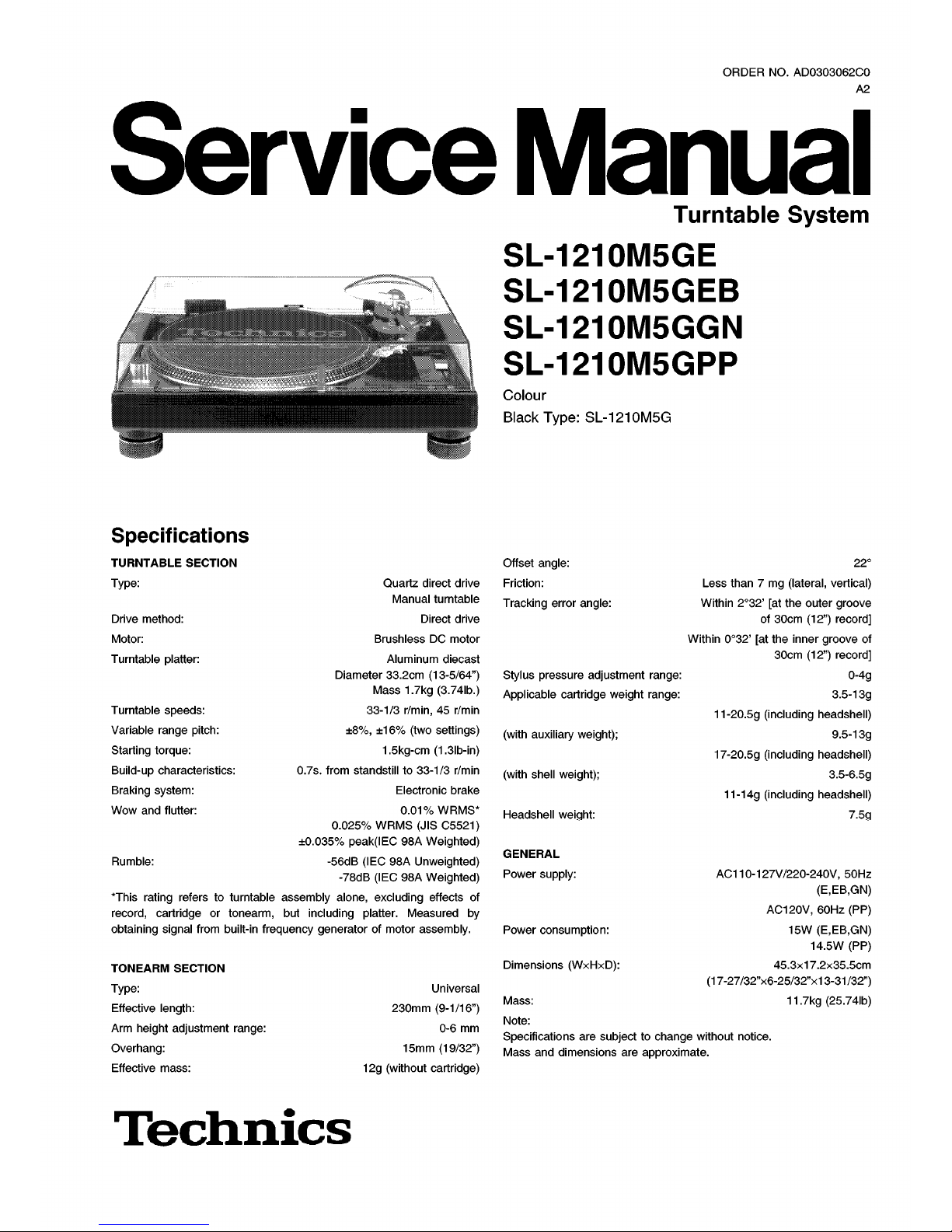
Turntable
System
SL
-
1210
M
5
GE
SL
-
1210
M
5
GEB
SL
-
1210
M
5
GGN
SL
-
1210
M
5
GPP
Colour
Black
Type
:
SL
-
1210
M
5
G
Specifications
TURNTABLE
SECTION
Type
:
Offset
angle
:
Friction
:
Tracking
errar
angle
:
22
°
Guartz
direct
drive
Manual
turntable
Direct
drive
Brushless
DC
motor
Aluminum
diecast
Diameter
33.2
cm
(
13
-
5
/
64
”
)
Mass
1.7
kg
(
3.74
lb
.
)
33
-
1
/
3
r
/
min
,
45
r
/
min
±
8
%
,
±
16
%
(
two
settings
)
1.5
kg
-
cm
(
1.3
lb
-
in
)
0.7
s
.
tram
standstill
to
33
-
1
/
3
r
/
min
Electronic
brake
0.01
%
WRMS
*
0.025
%
WRMS
(
JIS
C
5521
)
±
0.035
%
peak
(
IEC
98
A
Weighted
)
-
56
dB
(
IEC
98
A
Unweighted
)
-
78
dB
(
IEC
98
A
Weighted
)
*
This
rating
refers
to
turntable
assembly
alone
,
excluding
effects
of
record
,
cartridge
or
tonearm
,
but
including
platter
.
Measured
by
obtaining
signal
tram
built
-
in
frequency
generator
of
motor
assembly
.
Less
than
7
mg
(
lateral
,
vertical
)
Within
2
°
32
’
[
at
th
è
outer
groove
of
30
cm
(
12
”
)
record
]
Within
0
°
32
’
[
at
th
è
inner
groove
of
30
cm
(
12
”
)
record
]
0
-
4
g
3.5-13
g
11
-
20.5
g
(
including
headshell
)
9.5
-
13
g
17
-
20.5
g
(
including
headshell
)
3.5
-
6.5
g
11
-
14
g
(
including
headshell
)
Drive
method
:
Motor
:
Turntable
platter
:
Stylus
pressure
adjustment
range
:
Applicable
cartridge
weight
range
:
Turntable
speeds
:
Variable
range
pitch
:
Starting
torque
:
Build
-
up
characteristics
:
Braking
System
:
Wow
and
flutter
:
(
with
auxiliary
weight
)
;
(
with
shell
weight
)
;
Headshell
weight
:
7.5
g
GENERAL
Power
supply
:
Rumble
:
AC
110
-
127
V
/
220-240
V
,
50
Hz
(
E,EB
,
GN
)
AC
120
V
,
60
Hz(PP
)
15
W(E,EB
,
GN
)
14.5
W(PP
)
45.3
x
17.2
x
35.5
cm
(
17
-
27
/
32
”
x
6
-
25
/
32
”
x
13-31/32
”
)
11.7
kg
(
25.74
lb
)
Power
consumption
:
Dimensions
(
WxHxD
)
:
TONEARM
SECTION
Type
:
Effective
length
:
Arm
height
adjustment
range
:
Overhang
:
Effective
mass
:
Universal
230
mm
(
9
-
1
/
16
”
)
0-6
mm
15
mm
(
19
/
32
”
)
12
g
(
without
cartridge
)
Mass
:
Note
:
Specifications
are
subjecttochange
without
notice
.
Mass
and
dimensions
are
approximate
.
Techmcs
Page 2

SL
-
1210
M
5
GE
/
SL
-
1210
M
5
GEB
/
SL
-
1210
M
5
GGN/SL
-
1210
M
5
GPP
A
WARNING
This
Service
information
is
designed
for
experienced
repair
technicians
only
and
is
not
designed
for
use
by
th
è
generai
public
.
It
does
not
contain
warnings
or
cautionstoadvise
non
-
technical
individuals
of
potential
dangersinattempting
to
Service
a
product
.
Products
powered
by
electricity
shouldbeserviced
or
repaired
only
by
experienced
professional
technicians
.
Any
attempt
to
Service
or
repair
th
è
productorproducts
dealt
with
in
this
Service
information
by
anyone
else
could
resultinserious
injury
or
death
.
CONTENTS
Page
Page
1
Accessories
2
Controls
3
Turntable
System
pitch
adj
.
slider
replacement
instructions
.
4
4
Safety
Precaution
5
Caution
for
AC
Mains
Lead
6
Operation
Checks
and
Component
Replacement
Procedures
7
6.1
.
Checking
for
th
è
main
P
.C.B.
and
power
supply
P
.
C
.B.
—
7
6.2
.
Checking
for
th
è
pitch
control
(1)
P
.C.B.
6.3
.
Replacement
for
th
è
drive
coil
ass
’
y
and
FG
coil
ass
’
y
—
•
9
6.4
.
Replacement
for
th
è
tonearm
unit
6.5
.
Replacement
for
th
è
parts
mounted
onspeed
selector
P
.C.
B
.
and
power
switch
6.6
.
Replacement
for
th
è
LED
and
Stylus
illuminator
switch
-
12
7
Cautions
in
handling
of
thèblue
LED
8
Type
lllustration
of
IC
’
s
,
Transistors
and
Diods
9
Measurements
and
Adjustments
9.1
.
The
stateofset
and
th
è
use
apparatus
9.2
.
Measurements
and
Adjustments
9.3
.
Alignment
points
10
Schematic
Diagram
10.1
.
Schematic
Diagram
Notes
10.2
.
Schematic
Diagram
11
Printed
Circuit
Board
Diagram
12
Block
Diagram
13
Wiring
Connection
Diagram
14
Replacement
Parts
List
15
Cabinet
Parts
Location
15.1
.
Cabinet
15.2
.
Tonearm
16
Packaging
2
15
3
15
15
5
15
6
16
16
17
8
19
21
10
22
23
12
27
27
14
28
14
29
1
Accessories
•
Disc
slip
sheet
set
(
RGS
0005
Z
-
1
)
.
.
.
1
pc
.
•
Overhang
gauge
(
SFK
0135
-
01
)
..
.
1
pc
.
Teclmics
SDYmioe
.i.
-
Disc
slip
sheet
-
Transparent
sheet
•
Auxiliary
weight
(
SFPWG
17202
)
..
.
1
pc
.
•
Nuts
(
RHN
26003
)
..
.
2
pcs
.
•
Screws
(
short
) (
SFCZV
8801
-
1
)
..
.
2
pcs
.
•
Screws
(
long
)
(
SFPEV
9801
-
1
)
..
.
2
pcs
.
•
Washers
(
SFPEW
9601
)
...
2
pcs
.
•
Sticker
(
RQLC
0142
-
1
)
.
.
.
1
pc
.
•
EP
record
adaptor
(
SFWE
010
A
)
...
1
pc
.
•
Shell
weight
(
SFPZB
3501
)
.
.
.
1
pc
.
2
Page 3
SL
-
1210
M
5
GE
/
SL
-
1210
M
5
GEB
/
SL
-
1210
M
5
GGN
/
SL
-
1210
M
5
GPP
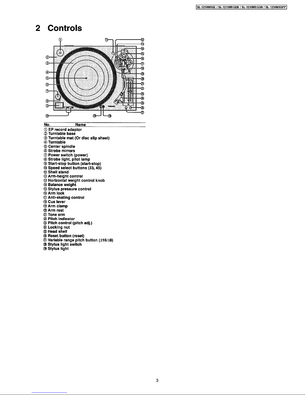
2
Controls
i
©
<S>
2
<
©
d
>
©
>
E
©
<
2
>
d
>
©
d
>
©
<g>
#
No
.
Name
©
EP
record
adaptor
©
Turntable
base
(
D
Turntable
mat
(
Or
disc
slip
sheet
)
®
Turntable
@
Center
spindle
®
Strobe
mirrors
®
Power
switch
(
power
)
®
Strobe
llght
,
pilot
lamp
CD
Start
-
stop
button
(
start
-
stop
)
®
Speed
select
buttons
(
33
,
45
)
®
Shell
stand
©
Arm
-
height
control
©
Horizontal
weight
control
knob
®
Balance
weight
©
Stylus
pressure
control
©
Arm
lock
©
Anti
-
skating
control
®
Cue
lever
®
Arm
clamp
©
Arm
rest
©
Tone
arm
®
Pitch
indicator
©
Pitch
control
(
pitch
adj
.
)
®
Locking
nut
©
Head
Shell
®
Reset
button
(
reset
)
@
Variable
range
pitch
button
(
±
16
/
±
8
)
®
Stylus
light
switch
©
Stylus
light
3
Page 4
SL
-
1210
M
5
GE
/
SL
-
1210
M
5
GEB
/
SL
-
1210
M
5
GGN/SL
-
1210
M
5
GPP
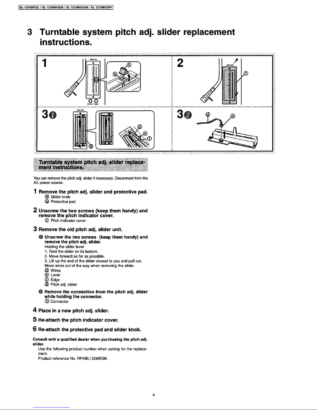
3
Turntable
System
pitch
adj
.
slider
replacement
instructions
.
®
B
.
4
m
5.1
2
i
3
vi
:
:
i
i
1
4
Ì
'
?
!
il
V.V
:
fi
il
?
1
•
1
'
:
ì
.
V
i
il
!
f
I
:
:
%
Hi
I
2
i
'
y
.
t
li
:
K
2
i
&
Si
555
HH
;
Ì
.
-
VV
.
5
,
’
H
-
,
,
-
.
H
,
-V-
|
i
-
HVHHHHH
'
i
'
iiiHrH
Hii
:
Turntable
System
pitch
adj
.
slider
replace
-
ment
instructions
.
You
can
remove
th
è
pitch
adj
.
slider
if
necessary
.
Disconnect
tram
th
è
AC
power
source
.
1
Remove
th
è
pitch
adj
.
slider
and
protective
pad
.
©
Slider
knob
(
B
)
Protective
pad
2
Unscrew
th
è
two
screws
(
keep
them
handy
)
and
remove
th
è
pitch
indicator
cover
.
©
Pitch
indicator
cover
3
Remove
th
è
old
pitch
adj
.
slider
unit
.
Unscrew
th
è
two
screws
(
keep
them
handy
)
and
remove
th
è
pitch
adj
.
slider
.
Holding
th
è
slider
lever
1
.
Rest
th
è
slideronits
bottom
.
2
.
Move
forward
as
far
as
possible
.
3
.
Lift
up
th
è
end
of
th
è
slider
closest
to
you
and
pul
ì
out
.
Move
wires
out
of
th
è
way
when
removing
th
è
slider
.
©
Wires
©
Lever
©
Edge
©
Pitch
adj
.
slider
Remove
thèconnection
from
th
è
pitch
adj
.
slider
while
holding
th
è
connector
.
©
Connector
4
Place
in
a
new
pitch
adj
.
slider
.
5
Re-attach
th
è
pitch
indicator
cover
.
6
Re
-
attach
th
è
protective
pad
and
slider
knob
.
Consult
with
a
qualified
dealer
when
purchasing
th
è
pitch
adj
.
slider
.
Use
th
è
following
product
number
when
asking
for
th
è
replace
-
ment
.
Product
reference
No
.
RFKBL
120
M
5
GK
.
4
Page 5
SL
-
1210
M
5
GE
/
SL
-
1210
M
5
GEB
/
SL
-
1210
M
5
GGN
/
SL
-
1210
M
5
GPP
4
Safety
Precaution
(
This
“
Safety
Precaution”is
applied
only
in
U
.S.A.
)
1
.
Before
servicing
,
unplug
th
è
power
cord
to
prevent
an
electric
shock
.
2
.
When
replacing
parts
,
use
only
manufacturer
’
s
recommended
components
for
safety
.
3
.
Check
th
è
condition
of
th
è
power
cord
.
Replace
if
wear
or
damage
is
evident
.
4
.
After
servicing
,
be
sure
to
restore
th
è
lead
dress
,
insulation
barriers
,
insulation
papers
,
shields
,
etc
.
5
.
Before
returning
th
è
serviced
equipment
to
th
è
customer
,
be
sure
to
make
th
è
following
insulation
resistance
test
to
prevent
th
è
customer
from
being
exposed
to
a
shock
hazard
.
Insulation
Resistance
Test
1
.
Unplug
th
è
power
cord
and
short
th
è
two
prongs
of
th
è
plug
with
a
jumper
wire
.
2
.
Turn
on
th
è
power
switch
.
3
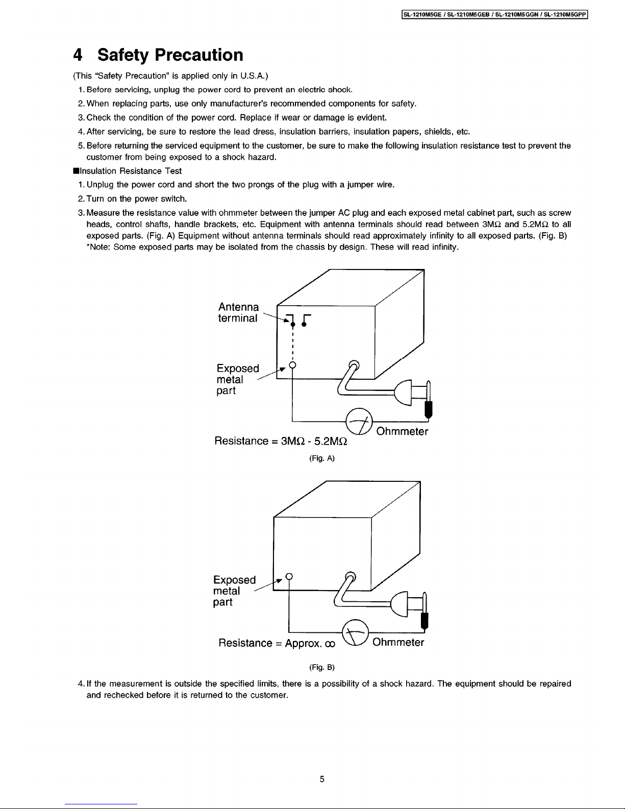
.
Measure
th
è
resistance
value
with
ohmmeter
between
th
è
jumper
AC
plug
and
each
exposed
metal
cabinet
part
,
such
as
screw
heads
,
control
shafts
,
handle
brackets
,
etc
.
Equipment
with
antenna
terminals
should
read
between
3
M
£
2
and
5.2
M
&
to
all
exposed
parts
.
(
Fig
.
A
)
Equipment
without
antenna
terminals
should
read
approximately
infinity
to
all
exposed
parts
.
(
Fig
.
B
)
*
Note
:
Some
exposed
parts
may
be
isolated
from
th
è
chassis
by
design
.
These
will
read
infinity
.
Antenna
terminal
/
2
o
Exposed
metal
-
Zt
part
Ohmmeter
Resistance
=
3
MQ
-
5.2
MQ
(
Fig
.
A
)
*
9
Exposed
metal
-
part
Ohmmeter
Resistance
=
Approx
.
oo
(
Fig
.
B
)
4
.
If
th
è
measurement
is
outside
th
è
specified
limits
,
there
is
a
possibility
of
a
shock
hazard.The
equipment
should
be
repaired
and
rechecked
before
it
is
returned
to
th
è
customer
.
5
Page 6
SL
-
1210
M
5
GE
/
SL
-
1210
M
5
GEB
/
SL
-
1210
M
5
GGN/SL
-
1210
M
5
GPP
5
Caution
for
AC
Mains
Lead
WARNING:DO
NOT
CONNECT
EITHER
WIRETOTHE
EARTH
TERMINAL
WHICH
IS
MARKED
WITH
THE
LETTER
E,BY
THE
EARTH
SYMBOL
OR
COLOURED
GREENORGREEN/YELLOW
.
(
For
United
Kingdom
)
(
“
EB
”
area
code
model
only
)
Foryour
safety
,
please
read
th
è
following
text
carefully
.
THIS
PLUG
IS
NOT
WATERPROOF
—
KEEP
DRY
.
This
appliance
is
supplied
with
a
moulded
three
pin
mains
plug
for
your
safety
and
convenience
.
A
5
-
ampere
fuse
is
fitted
in
this
plug
.
Should
th
è
fuse
needtobe
replaced
please
ensure
that
th
è
replacement
fuse
has
a
rating
of
5
-
ampere
and
that
it
is
approved
by
ASTAorBSI
to
BS
1362
.
Check
for
th
è
ASTA
mark
<
^
>
or
th
è
BSI
mark
^
on
th
è
body
of
th
è
fuse
.
Before
use
Remove
th
è
connector
cover
.
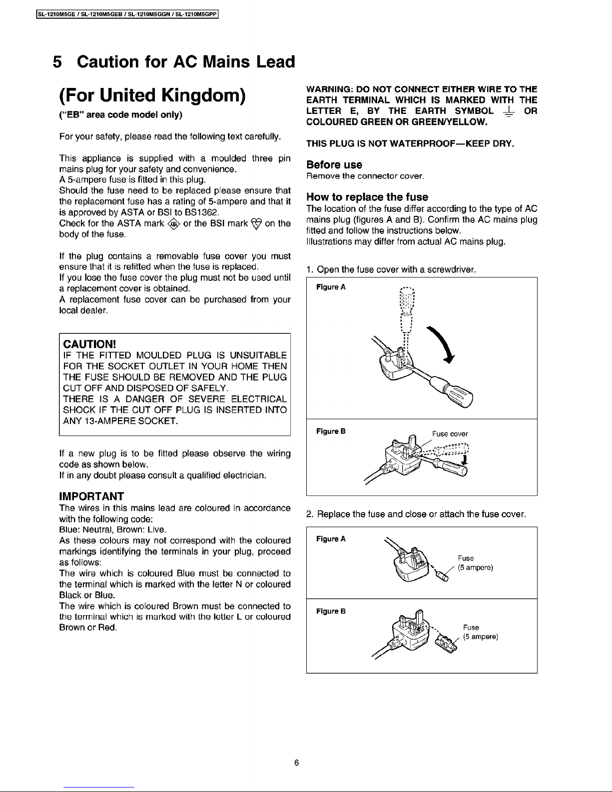
How
to
replace
th
è
fuse
The
location
of
th
è
fuse
differ
according
to
th
è
type
of
AC
mains
plug
(
figures
A
and
B
)
.
Confirm
th
è
AC
mains
plug
fitted
and
follow
th
è
instructions
below
.
Illustrations
may
differ
from
actual
AC
mains
plug
.
If
th
è
plug
containsaremovable
fuse
cover
you
must
ensure
that
it
is
refitted
when
th
è
fuse
is
replaced
.
If
you
lose
th
è
fuse
cover
th
è
plug
must
not
be
used
until
a
replacement
cover
is
obtained
.
A
replacement
fuse
cover
can
be
purchased
from
your
locai
dealer
.
1
.
Open
th
è
fuse
cover
with
a
screwdriver
.
CAUTION
!
IF
THE
FITTED
MOULDED
PLUG
IS
UNSUITABLE
FOR
THE
SOCKET
OUTLET
IN
YOUR
HOME
THEN
THE
FUSE
SHOULDBEREMOVED
AND
THE
PLUG
CUT
OFF
AND
DISPOSED
OF
SAFELY
.
THERE
ISADANGER
OF
SEVERE
ELECTRICAL
SHOCK
IF
THE
CUT
OFF
PLUG
IS
INSERTED
INTO
ANY
13
-
AMPERE
SOCKET
.
If
a
new
plug
istobe
fitted
please
observe
th
è
wiring
code
as
shown
below
.
If
in
any
doubt
please
consult
a
qualified
electrician
.
IMPORTANT
The
wires
in
this
mains
lead
are
coloured
in
accordance
with
th
è
following
code
:
Blue:Neutral
,
Brown:Live
.
As
these
colours
may
not
correspond
with
th
è
coloured
markings
identifying
th
è
terminals
in
your
plug
,
proceed
as
follows
:
The
wire
whichiscoloured
Blue
must
be
connected
to
th
è
terminal
whichismarked
with
th
è
letter
N
or
coloured
Black
or
Blue
.
The
wire
which
is
coloured
Brown
must
be
connected
to
th
è
terminal
whichismarked
with
th
è
letter
L
or
coloured
Brown
or
Red
.
2
.
Replace
th
è
fuse
and
doseorattach
th
è
fuse
cover
.
Figure
A
6
Page 7
SL
-
1210
M
5
GE
/
SL
-
1210
M
5
GEB
/
SL
-
1210
M
5
GGN
/
SL
-
1210
M
5
GPP
6
Operation
Checks
and
Component
Replacement
Procedures
•
This
section
describes
procedures
for
checking
th
è
operation
of
th
è
major
printed
Circuit
boards
and
replacing
th
è
main
components
.
•
For
reassembly
after
operation
checks
or
replacement
,
reverse
th
è
respective
procedures
.
Special
reassembly
procedures
are
described
only
when
required
.
(
Step
2
)
©
x
5
o
t
©
©
t
©
t
/
il
(
;
=
-
=
-
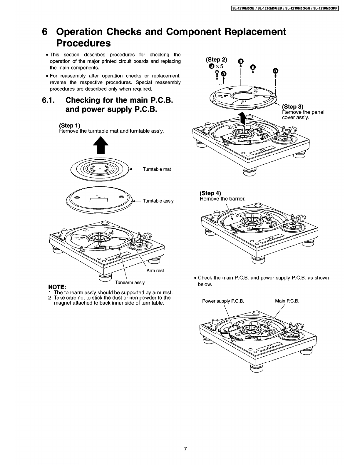
Checking
for
thèmain
P
.C.B.
and
power
supply
P
.C.B.
6.1
.
fi
'
(
Step
3
)
Remove
th
è
panel
cover
ass
'
y
.
(
Step
1
)
Remove
th
è
turntable
mat
and
turntable
ass
'
y
.
&
o
Turntable
mat
<
(
Step
4
)
Remove
th
è
barrier
.
&
Turntable
ass
'
y
&
%
Arm
rest
•
Check
th
è
main
P
.C.B.
and
power
supply
P
.C.B.
as
shown
below
.
Tonearm
ass
'
y
NOTE
:
1
.
The
tonearm
ass
'
y
should
be
supported
by
arm
rest
.
2
.
Take
care
not
to
stick
th
è
dustoriron
powder
to
th
è
magnet
attachedtoback
inner
side
of
turn
table
.
Power
supply
P
.C.
B
.
Main
P
.
C
.B.
7
Page 8
SL
-
1210
M
5
GE
/
SL
-
1210
M
5
GEB
/
SL
-
1210
M
5
GGN/SL
-
1210
M
5
GPP
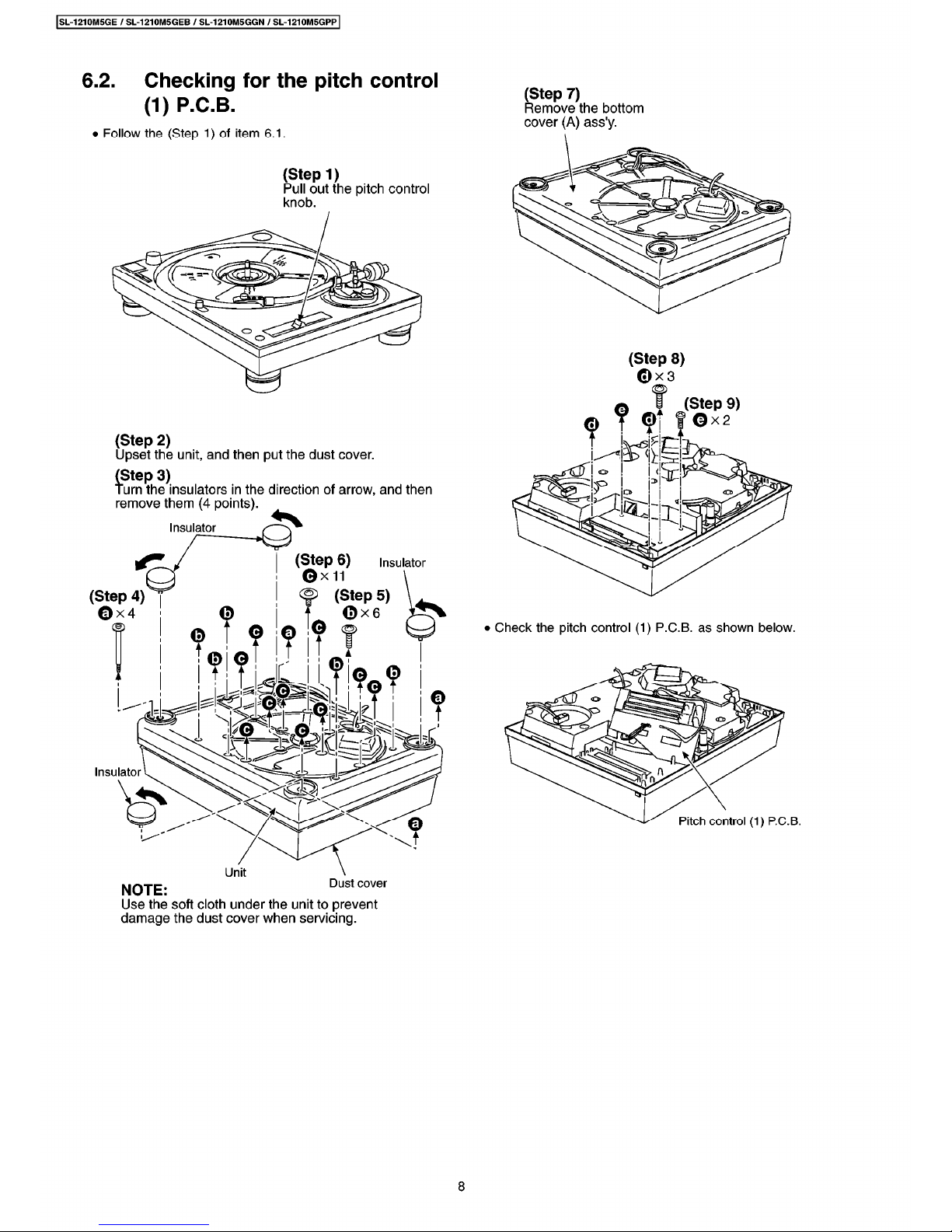
6.2
.
Checking
for
th
è
pitch
control
(1)
P
.C.B.
(
Step
7
)
Remove
th
è
bottom
cover
(A)
ass
'
y
.
•
Follow
th
è
(
Step
1
)
of
item
6.1
.
(
Step
1
)
Pul
ì
out
th
è
pitch
control
knob
.
(
Step
8
)
©
x
3
(
Step
9
)
©
x
2
(
Step
2
)
Upset
th
è
unit,and
then
put
th
è
dust
cover
.
(
Step
3
)
Turn
th
è
insulators
in
th
è
direction
of
arrow
,
and
then
remove
them
(
4
points
)
.
Insulator
(
Step
6
)
©
X
11
Insulator
S
>
(
Step
5
)
(
Step
4
)
©
X
4
•
Check
th
è
pitch
control
(1)
P
.C.
B
.
as
shown
below
.
<
&
<o>
fe
.
4
Insulator
Pitch
control
(
1
)
P
.
C
.
B
.
Dust
cover
NOTE
:
Use
th
è
soft
cloth
under
th
è
unit
to
prevent
damage
th
è
dust
cover
when
servicing
.
8
Page 9
SL
-
1210
M
5
GE
/
SL
-
1210
M
5
GEB
/
SL
-
1210
M
5
GGN
/
SL
-
1210
M
5
GPP
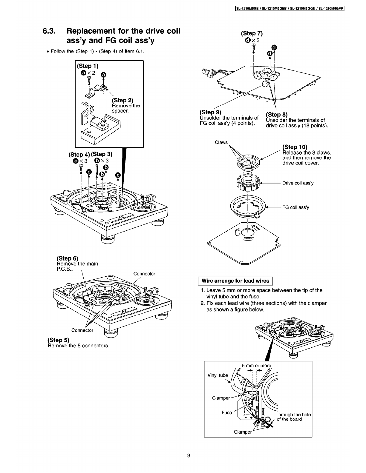
6.3
.
Replacement
for
thèdrive
coil
ass
’
y
and
FG
coil
ass
’
y
•
Follow
th
è
(
Step
1
)-(
Step
4
)
of
item
6.1
.
(
Step
7
)
0
x
3
(
Step
1
)
0
x
2
7
(
Step
2
)
Re
move
th
è
spacer
.
(
Step
9
)
Unsolder
th
è
terminals
of
FG
coil
ass
'
y
(
4
points
)
.
(
Step
8
)
Unsolder
th
è
terminals
of
drive
coil
ass
'
y
(
18
points
)
.
Claws
(
Step
10
)
Release
th
è
3
claws
,
and
then
remove
th
è
drive
coil
cover
.
(
Step
4
)
(
Step
3
)
©
x
3
0
x
3
Drive
coil
ass
'
y
FG
coil
ass
'
y
(
Step
6
)
Remove
th
è
mairi
P
.C.B.
.
Connector
Wire
arrenge
for
lead
wires
1
.
Leave
5
mirri
or
more
space
between
th
è
tip
of
th
è
vinyl
tube
and
th
è
fuse
.
2
.
Fix
each
lead
wire(three
sections
)
with
th
è
damper
as
shown
a
figure
below
.
Connector
(
Step
5
)
Remove
th
è
5
connectors
.
9
Page 10

SL
-
1210
M
5
GE
/
SL
-
1210
M
5
GEB
/
SL
-
1210
M
5
GGN/SL
-
1210
M
5
GPP
6.4
.
Replacement
for
th
è
tonearm
unit
•
Follow
th
è
(
Step
1
)
of
item
6.1
.
•
Follow
th
è
(
Step
2
)-(
Step
7
)
of
item
6.2
.
(
Step
8
)
©
x
2
(
Step
7
)
0
x
2
(
Step
10
)
Remove
th
è
arm
base
cover
piate
.
(
Step
1
)
©
x
5
?
9
(
Step
2
)
Remove
th
è
bottoni
cover
(B)
.
(
Step
5
)
(
Step
3
)
(
Step
9
)
Release
th
è
2
claws,and
then
remove
th
è
phono
cord
damper
and
phono
cord
spacer
.
(
Step
12
)
(
Step
14
)
Remove
th
è
PU
output
P
.C.B.
.
(
Step
13
)
0
(
Step
4
)
Remove
th
è
lug
terminal
.
Tonearm
unit
NOTE
:
Hold
th
è
tonearm
unit
with
hand
when
removing
th
è
3
screws
(
©
)
.
Cabinet
ass
'
y
Tonearm
ass
'
y
(
Step
6
)
Separate
th
è
dust
cover
and
th
è
cabinet
ass
'
y
,
and
then
remove
th
è
tonearm
ass
'
y
.
Dust
cover
(
Step
11
)
Unsolder
th
è
terminals
(
5
points
)
.
10
Page 11

SL
-
1210
M
5
GE
/
SL
-
1210
M
5
GEB
/
SL
-
1210
M
5
GGN
/
SL
-
1210
M
5
GPP
When
passing
th
è
lead
wire
through
\
\
ir
th
è
hole
,
for
easy
operation
,
wrap
th
è
jp
ends
of
5
lead
wires
IW
with
tape
.
(
Step
3
)
Pass
th
è
5
lead
wires
through
th
è
hole
of
arm
basement
.
(
Step
15
)
Release
th
è
arm
rest
.
Arm
rest
(
Step
4
)
Instali
th
è
tonearm
unit
.
(
Step
16
)
0
x
2
P
(
Step
5
)
Support
th
è
tonearm
unit
with
arm
rest
.
Arm
rest
Arm
base
(
Step
6
)
Tighten
th
è
tonearm
unit
screws
.
0
x
2
/
Tonearm
unit
%
(
Step
17
)
Remove
th
è
tonearm
unit
.
Reassembly
procedures
for
tonearm
ass
'
y
(
Stepl
)
(
Step
2
)
Rotate
th
è
arm
base
knob
Rotate
th
è
canceler
knob
in
in
th
è
direction
of
arrow
,
th
è
direction
of
arrow
,
and
and
then
align
th
è
pointer
then
align
th
è
pointer
with
with
th
è
scale
"0"
.
(
Step
7
)
Remove
th
è
tape
of
lead
wire
.
th
è
scale
"0"
.
Pointer
Pointer
Canceler
knob
Arm
base
knob
11
Page 12

SL
-
1210
M
5
GE
/
SL
-
1210
M
5
GEB
/
SL
-
1210
M
5
GGN/SL
-
1210
M
5
GPP
6.5
.
Replacement
for
th
è
parts
mounted
onspeed
selector
P
.C.B.
and
power
switch
•
Follow
th
è
(
Step
1
)
of
item
6.1
.
•
Follow
th
è
(
Step
2
)
-
(
Step
7
)
of
item
6.2
.
6.6
.
Replacement
for
th
è
LED
and
Stylus
illuminator
switch
•
Follow
th
è
(
Step
1
)
of
item
6.1
.
•
Follow
th
è
(
Step
2
)-(
Step
7
)
of
item
6.2
.
Cautions
1
.
For
lightening
th
è
needle
tip
,
this
unit
uses
a
blue
LED
instead
of
a
conventional
lamp
.
The
blue
LED
is
very
much
sensitivetostatic
electricity
;
therefore
,
be
especially
careful
of
handling
it
.
2
.
This
LED
may
be
destroyed
or
worsened
by
th
è
static
electricity
charged
in
clothes
and
human
bodies
.
When
handling
and
repairing
th
è
LED
,
be
especially
careful
of
such
destruction.Be
sure
to
take
necessary
measures
such
as
wearing
a
wrist
strap
.
(
Step
1
)
©
x
2
T
(
Step
1
)
(
CT
<a>
©
(
Step
2
)
<o>
<
a
>
<
o
>
(
Step
2
)
Remove
th
è
LED
unit
.
0
\
(
Step
4
)
Remove
th
è
lamp
case
.
©
(
Step
4
)
e
a
©
(
Step
3
)
Speed
selector
P
.C.
B
.
1
À
J
&
&
Syilus
illuminator
switch
&
_
T
7
AJV
.
3
3
WLI
O
,
V
<
©
p
5
)
x
2
Power
switch
(
Step
3
)
Remove
th
è
speed
selector
P
.C.B..
12
Page 13

SL
-
1210
M
5
GE
/
SL
-
1210
M
5
GEB
/
SL
-
1210
M
5
GGN
/
SL
-
1210
M
5
GPP
(
Step
7
)
Remove
th
è
LED
.
Si
&
LED
P
.C.B.
e
&
)
o
)
Black
o
Red
(
Step
6
)
Unsolder
th
è
terminals
of
lead
wire
(
2
points
)
.
13
Page 14

SL
-
1210
M
5
GE
/
SL
-
1210
M
5
GEB
/
SL
-
1210
M
5
GGN/SL
-
1210
M
5
GPP
7
Cautions
in
handling
of
th
è
blue
LED
•
For
lightening
th
è
needle
tip
,
this
unit
uses
a
blue
LED
instead
of
a
conventional
lamp
.
The
blue
LED
is
very
much
sensitive
to
static
electricity
;
therefore
,
be
especially
careful
of
handling
it
.
A
Be
careful
of
destruction
by
th
è
static
electricity
•
This
LED
may
be
destroyed
or
worsened
by
th
è
static
electricity
charged
in
clothes
and
human
bodies
.
When
handling
and
repairing
th
è
LED
,
be
especially
careful
of
such
destruction
.
Be
su
re
to
take
necessary
measures
such
as
wearing
a
wrist
strap
.
Grounding
for
electrostatic
breakdown
prevention
1
.
Human
body
grounding
•
Use
th
è
anti-static
wrist
strap
to
discharge
th
è
static
electricity
from
your
body
.
(
Fig
.
12
-
1
)
2
.
Work
table
grounding
•
Put
a
conductive
material(sheet
)
or
steel
sheet
on
th
è
area
where
th
è
traverse
deck
(
optical
pick
-
up
)
is
placed
,
and
ground
th
è
sheet
.
(
Fig
.
12
-
2
)
*
ir
Iron
piate
or
some
metals
to
conduct
electricity
(
Fig
.
12-2
)
Caution
:
The
static
electricity
of
your
clothes
will
not
be
grounded
through
th
è
wrist
strap
.
So
take
care
not
to
let
your
clothes
touch
th
è
traverse
deck
(
optical
pick
-
up
)
.
Wrist
strap
(
Anti
-
static
bracelet
)
1
M
£
2
777777
/
(
Fig
.
12
-
1
)
8
Type
lllustration
of
IC
’
s
,
Transistors
and
Diods
2
SD
637
-
QRS
D
2
SBA
20
SVDPR
3902
S
-
9
LN
21
CAL
RXQ
1004
_
B3AFA
0000034
LMW9A
8
BYB
0
A
1
Anode
Anode
Anode
Cathde
A
Cathde
A
(
f
£
—
Ca
Cathde
A
(
§
)
Ca
Ca
14
Page 15

SL
-
1210
M
5
GE
/
SL
-
1210
M
5
GEB
/
SL
-
1210
M
5
GGN
/
SL
-
1210
M
5
GPP
9
Measurements
and
Adjustments
9.1
.
The
state
of
set
and
th
è
use
apparatus
PITCH
CONTROL
±
0
%
ADJUSTMENT
VR
501
É
~
[
•
Make
th
è
following
adjustments
after
replacing
parts
as
IC
’
s
,
Transistore
,
Diodes
,
etc
.
•
Condition
of
th
è
set
.
1
.
Power
switch
:
ON
2
.
Pitch
control
:
Center
position
3
.
Speed
selector
switch
:
33
-
1
/
3
r
/
min
•
Instruments
to
be
used
-
Tester
-
Frequency
counter
Measuring
apparatus
oo
o
©
O
XL
Lever
o
+
c
>
Center
ir
o
©
O O P
PITCH
CONTROL
(
2
)
P
.
C
.
B
.
053
PITCH
CONTROL
(1)
P
.C.B.
9.2
.
Measurements
and
Adjustments
9.2
.1.
Pitch
control
±
0
%
adjustment
(
PITCH
)
1
.
Connect
th
è
frequency
counter
[
(+)
:
TP
1
,
(-)
:
GND
]
and
turn
th
è
power
supply
ON
.
2
.
Set
th
è
pitch
control
knob
(
VR
303
)
to
“
0
”
(
center
position
)
.
(
Indicator
lights
up
.
)
3
.
Adjust
VR
501
so
that
th
è
output
becomes
th
è
maximum
.
(
Fig
.
2
)
9.2
.2.
Brake
adjustment
(
BRAKE
)
I
.
Adjust
VR
201
so
that
th
è
rotation
at
33
-
1
/
3
r
/
min
stops
within
th
è
stop
range
after
pressing
th
è
stop
button
.
(
Fig
.
l
)
(
Fig
.
3
)
9.3
.
Alignment
points
(
Fig
.
2
)
The
direction
of
EP
record
adaptor
.
Turntable
Turntable
sheet
Record
disc
(
30
cm
)
Stop
range
Stop
signal
(
Stylus
tight
position
)
(
Fig
.
3
)
PITCH
CONTROL
±
0
%
ADJUSTMENT
VR
501
Measuring
apparatus
oo
o
Lever
O
-
a
*
r
—
Center
s
©
o
m
O O P
PITCH
CONTROL
(2)
P
.
C
.B.
PITCH
CONTROL
(1)
P
.C.B.
(
Fig
.
1
)
15
Page 16

SL
-
1210
M
5
GE
/
SL
-
1210
M
5
GEB
/
SL
-
1210
M
5
GGN/SL
-
1210
M
5
GPP
10
Schematic
Diagram
10.1
.
Schematic
Diagram
Notes
S
201
SPEED
SELECTOR
(
33
-
1
/
3
r
/
min
)
switch
.
SPEED
SELECTOR
(
45
r
/
min
)
switch
.
START
/
STOP
switch
in
“
OFF
”
position
.
STYLUS
ILLUMINATOR
switch
in
“
ON
”
position
.
PITCH
RESET
switch
in
“
ON
”
position
.
PITCH
SELECT
(
±
8
%
/
±
16
%
)
switch
in
“
±
16
%
”
position
.
POWER
switch
in
“
ON
”
position
.
VOLTAGE
SELECTOR
switch
in
“
220
-
240
V
”
position
.
[
E,EB
,
GN
]
BRAKE
ADJUSTMENT
VR
.
PITCH
CONTROL
ADJUSTMENT
VR
.
PITCH
CONTROL
±
0
%
ADJUSTMENT
5202
5203
S
401
S
501
:
S
502
:
S
601
:
S
602
:
VR
201
VR
303
VR
501
VR
.
•
The
voltage
value
and
waveforms
are
th
è
reference
voltage
of
this
measured
by
DC
electronic
voltmeter
(
high
impedance
)
and
oscilloscope
on
th
è
basis
of
chassis
.
Accordingly
,
there
may
arise
some
errors
in
th
è
voltage
values
and
waveforms
depending
upon
th
è
internai
impedance
of
th
è
tester
or
th
è
measuring
unit
.
No
mark
:
Voltage
when
at
a
stop
(
)
:
Voltage
during
rotation
•
Signal
line
:
+
B
line
•
Important
safety
notice
:
Components
identified
by
A
mark
have
special
characteristics
important
for
safety
.
When
replacing
any
of
these
components
,
use
only
manufacture
’
s
specified
parts
.
•
This
schematic
diagram
may
be
modified
at
any
time
with
th
è
development
of
new
technology
.
16
Page 17

SL
-
1210
M
5
GE
/
SL
-
1210
M
5
GEB
/
SL
-
1210
M
5
GGN/SL
-
1210
M
5
GPP
10.2
.
Schematic
Diagram
0
REGULATOR
CIRCUIT
B
POWER
SUPPLY
CIRCUIT
For
[PP]
area
.
4
}
For
[
EB
,
GN
]
areas
.
35.8
V
21
V
r
AS
601
(
POWER
)
Q
1
AC
601„0.047
C
2
SD
126507
[
21.6
V
REGULATOR
I
II
A
r
IA
R
601
3.3
M
I
\
POWER
SUPPLY
CIRCUIT
S
601
4
^
(
POWER
)
,
Q
For
[
E
]
area
.
i
H
OFF
ON
1
A
F
2
I
125
V
1.2
A
4
j
-
<
r
^
o
-
r
)
—
D
1
Q
DRIVE
CONTROL
CIRCUIT
AFI
125V250
mA
ATI
ATI
D
2
SBA
20
A
F
2
A
TP
1
TP
3
Z
ì
i
S
602
(
VOLTAGE
SELECTOR
)
Q
2
o
T1A
i
35.8
V
21.6
V
1
AC
1
11
°
i
+
(
2
)
o
>
2
:
^
6
O
r
Q
2
,
3
T
A
F
1
T
250
mA
AC
601AR601
0.047
1/2
W
4.7
!
4
i
I
A
I
AC
LINE
'
110-120
VS
/
220-240
V
,
50/60
Hz
.
2
SD
637
-
QRS
REGULATOR
OP
I
&
I
I
h
1
AC
120
V
(
60
Hz
)
ò
4
22.1
V
~
CM
§
1
+
22.1
V
J
-
2
?
og
2
Z
8
AC
30
V
UC
30
V
I
I
R
2
4
CM
IO
CM
TP
2
«
I
I
'
1
'
I
I
6.8
K
L
.
i
vw
AC
2
?
t
R
5
SS
5.4
V
R
4
G
470
470
?
i
—
wv
wv
TP
4
2
*
23
l
o
TP
5
<
?
4
4
4
<
21
V
>
2
_
+
•
S
501
•
•
•
OFF
,
5.3
V
Q
°
T
OWT
"
S
501
—
ON.OV
«
8
+
o
%
21
CM
CD
^
J
>
•
ROTATION
II
0
>
y
.
CM
*
*
ce
CO
STOP
<
$
0.8
V
o
2
START
I
5
dI
cc
<
N
5
3
V
2.9
V
R
218
CN
IV
1
K
C
215
R
203
5
V10V
Q
203
2
SC
2458
GR
FG
AMP
0
V
3.8
ws
.
33
rpm
,
20
ms
.
45
rpm
,
15
ms
.
TP
12
O
-
i
F
I
gei
3.8
V
TP
11
.
0.4
V
R
206
TP
18
W
«
CM
>
2
E
WV
n
Oo
R
221
18
18
K
470
CM
r
-
+
R
207
56
K
•
ROTATION
-
Wv
R
208
220
K
|
—
Wv
—
ov
R
204
WV
\
TP
20
2.7
K
O
io
C
108
.
.
25V100
<
2
^
+
o
®
R
107
1
-
WV
9
V
o
C
211
C
110
"
+
0.1
C
204
0.047
POSITION
DET
.
COIL
0.22
II
5
V
C
210
..
0
,
22
•
ROTATION
S
203
-
-
Push
TP
19
II
n
R
108
10
K
TP
21
^
S
*
N
WV
R
209
330
K
(
.
—
wv
—
u
1
V
TP
17
O
—
i
CM
/
1.5
£
C
111
5600
P
O
è
“
>
+
§
CM
CO
T
-
+
oK
\
n
33
rpm
—
20
ms
.
45
rpnr
*
-
15
ms
.
wv
30
V
o
P
3
R
205
120
K
CD
TP
7
+
$
3
E
R
210
18
K
TP
16
L
WV
O
WV
o
3
50
KHz
A
CM
TP
22
TP
23
P
2
O O
2
l
20
W
$
.
ss
OC
”
*
(
2.8
V
)I(
0.3
V
)
7
V
Ì
5.9
V
C
107
C
112
R
104
E
P
1
o
0.3
V
0.5V8.1
V
1.2
V5V
0.2
V
3.2V3.2
V
I
2.8
V
50
V
4.7
47
K
0.1
II
»
7
wv
15
V
fl
8
VHl
9
J
fi
3
VH14HH
15
V
-
<
16
HH
1
A
)
1
•
STOP
,
0
V
o o o
<
»
o
cc
5
o
£
<
D
1.2
V
O
>
o
_
2
CD
CD
50
KHz
(
0
Li
-
LLI
LL LL
(
2.8
V
)
IC
201
AN
6680
SYSTEM
CONTROL
0
V
20.7
V
|
(
Ì
5
V
>
33
rpm
*
-
20
ms
.
45
rpnv
15
ms
.
•
ROTATION
Jl
5.8
V
115.8V115.9
V
(
Ì
6
)
—
HI
15.9
V
121.1
Vi
21V21
V
J
20.7
V
7
>
—
(
m
—
(
Ì
9
W
—
(
20
)—(
2
Ì
)
"
^
0.2
V
:
3
)
:
4
)
co
co
o
IC
101
I
S
!
AN
6675
L
TURNTABLE
^
DRIVE
J
Q
O O
o
2
o o
z
51
<
o
co
CM
8
o
co
o
CL
co
0
-
£
z
z
g
co co
cn
o
o
2
8
3
o
E
O O
CD
CD
CO
> >
LL
5.2
V
•
ROTATION
I
”
41
V
—
(
10
>
-
H
9
8
6
3
[
1
4
1
0
V
R
201
33
rpm
•••
20
ms
.
45
rpm
--
*
15
ms
.
0.2V9.4V10V0
V
3.3V3.4
V
2.1
V
3.4V3.9
V
2.7
V
560
X
-
WV
—
11
V
R
202
0
V
D
10
K
A/W
—
I
TP
15
10
V
.
R
101
10
K
WV
X
*
4
8
§
>
2
Z
3
d
50
KHz
ARMATURE
9.4
V21V
in
^
CC
'
*
l
o
C
213
470
P
4.13
MHZ
COIL
I
Q
201
2
SC
1846
-
QRS
REGULATOR
BRAKE
A
1
3.8
V
TP
8
"
N
ADJ
.
TP
9
mm
A
2
1.2
V
Li
i
o
“
/
II
0
V
A
3
8
m
a
.
•
S
501
—
ON
rw
-
v
•
STOP
*
S
501
—
OFF
0.9
V
cc
®
80
:
8
§
2
Z
+
^
>
:
2
E
+
l
§
2
Z
+
5.6
V
oc
n
m
5.6
V
M
-
8
ov
+
3.8
ws
.
TP
29
33
rpnr
**
10
ms
.
45
rpm
**
*
7.3
ms
.
§
1
*
>
O
T
-
5
dT
oc
VR
303
Center
,
3.8
ws
.
VR
303
-
%
,
4.1
W
s
.
VR
303
+
%
,
3.6
WS
.
c
CM
o
17
V
R
211
4.7
K
R
214
©
?
1
22
K
0.2
V
11
—
WV
wv
O
)
R
213
in
<
£
fi
ó
T
Q
202
0
1
2
SD
637
-
QRS
LED
DRIVE
i
—
O
TP
13
TP
14
1.2
K
¥
WV
5
-
1
Q
5
11
-
O
35
I
a
TP
28
CN
103
CN
101
“
Kp
©®©
©
^
^
OXYXBXMKP
)
M
1
X
2
X
3
,
1
H
OUTPUT
CIRCUIT
B
PWB
CARTRIDGEl
R
510
R
B
,
2.2
K
i
i
D
201,202
SVDPR
3902
S
-
9
i
R
509
.
’
2.2
K
1
sr
Lch
.
+
)
n
S
401
(
STYLUS
ILLUMI
NATO
R
SWITCH
)
CN
106
O
1
CM
I
—
CO
cc
D
203
-
206
LN
21
CAL
(
STROBE
ILLUMINATOR
)
OUTPUT
Sor
I
(
f
ò
ia
I I
I
R
-
J
1
?
*
*
Rch
WV
VR
303
(
PITCH
ADJ
.
)
co
^
I
I
I
i
E
.
P
i
GND
E
D
203
D
204D205D206
R
507
R
508
A
<
2
±
Ss
-
1
”
S
'
X
o
co
3
^
VR
501
1
K
820
STROBE
ILLUMINATOR
CIRCUIT
A
1
•
—
Wv
—
O
-
WV
—
wv
T
\
PITCH
CONTROL
SL
-
1210
M
5
G
(
E,EB
,GN,
PP
)
DRIVE
CONTROL
,
POWER
SUPPLY
,
REGULATOR
,
PITCH
C
0
NTR0L
(1)
,
PITCH
C
0
NTR0L
(2)
,
SPEED
SELECTOR
,
STROBE
ILLUMINATOR
.
STYLUS
ILLUMINATOR
SWITCH
,
OUTPUT
CIRCUIT
GAIN
ADJ
.
B
STYLUS
ILLUMINATOR
IH
SWITCH
CIRCUIT
SPEED
SELECTOR
CIRCUIT
Q
PITCH
CONTROL
(1)
CIRCUIT
Q
PITCH
CONTROL
(2)
CIRCUIT
T T
1
2
3
4
6
8
9
10
11
12
5
7
17
Page 18

SL
-
1210
M
5
GE
/
SL
-
1210
M
5
GEB
/
SL
-
1210
M
5
GGN
/
SL
-
1210
M
5
GPP
18
Page 19

SL
-
1210
M
5
GE
/
SL
-
1210
M
5
GEB
/
SL
-
1210
M
5
GGN
/
SL
-
1210
M
5
GPP
11
Printed
Circuit
Board
Diagram
Note
:
This
printed
Circuit
board
diagram
may
be
modified
at
any
time
with
th
è
development
of
new
technology
.
H
IBI
STROBE
ILLUMINATOR
P
.C.B.
PI
REGULATOR
P
.C.B.
H
DRIVE
CONTROL
P
.C.B.
0
TP
27
GND
©
I
E
G
©
^
B
(
REP
3552
A
-
S
)
(
REP
3461
B
-
M
)
F
OUTPUT
P
.C.B.
GND
E
OUTPUT
777
D
SFDP
122
-
23
»
!
{
a
|
(
SFDH
122
-
09
E
3
)
l
START
/
I
STOP
<
!
>
WHT
Lch
I
BLU
c
I
<
!
>
GRN
I
R
eh
RED
BLK
CARTRIDGE
B
(
REP
3461
B-M
)
A
SL
-
1210
M
5
G
(
PP
,E,
EB
,
GN
)
DRIVE
CONTROUREGULATOR
/
STROBE
ILLUMINATOR
/
SPEED
SELECTOR
/
OUTPUT
P
.
C
.
B
.
T
T
I
T
T
I
T
I
I
T
I
T
1
1
2
3
4
5
6
7
8
9
10
11
12
13
19
Page 20

SL
-
1210
M
5
GE
/
SL
-
1210
M
5
GEB
/
SL
-
1210
M
5
GGN
/
SL
-
1210
M
5
GPP
POWER
SUPPLY
P
.C.B.
For
[
E,EB
,
GN
]
areas
.
B
H
RI
PITCH
CONTROL
(I)
P
.C.B.
POWER
SUPPLY
P
.C.B.
For
[PP]
area
.
B
13
PITCH
CONTROL
(2)
P
.C.
B
.
2677
/
.
S
602
(
VOLTAGE
G
SELECTOR
)
‘
r
j
J
(
BRN
)
CN
106
«
©
«
few
I
I
s
I
I
i
—
i
For
[E]
area
.
i
LP
1
S
601
I
F
(
POWER
)
8
FW
105
For
[
EB
,
GN
]
areas
.
§
Mk
C
6
®
J
É
1
F2T1A
r
E
A
(
SFDP
122
C
09
E
)
FW
106
(
REP
2093
A
-
1
[E]
REP
2346
A
-
1
[
EB
,
GN
]
.
&
D
%
r
.
P
503
m
[
i
il
0501
dH
)
sf
i
STYLUS
ILLUMINATOR
SWITCH
P
.C.B.
:
D
502D501
(
±
8
)
(
±
16
)
c
rara
i
(
REP
3458
BB
-
S
)
S
401
I
C
1
OFF
PITCH
ADJ
.
A
r
I
*
D
504
H
—
v
R
509
C
i
L
±
16
J
R
510
2677
AA
B
@
*
®
(
REP
3458
BA
-
S
)
(
REP
3553
A
-
S
)
A
SL
-
1210
M
5
G
(
PP
,E,
EB
,
GN
)
POWER
SUPPLY
/
STYLUS
ILLUMINATOR
SWITCH
/
PITCH
CONTROL
(1),(
2
)
P
.
C
.
B
.
I
T
I
T
T
I
T
T
I
T
I
T
1
1
2
3
4
5
6
7
8
9
10
11
12
13
20
Page 21

SL
-
1210
M
5
GE
/
SL
-
1210
M
5
GEB
/
SL
-
1210
M
5
GGN
/
SL
-
1210
M
5
GPP
12
Block
Diagram
POSITION
DETECTOR
COIL
+
B
1
-
4
-
T
1
<
!
>
S
601
P
3
For
[PP]
area
.
(
POWER
)
3
oc
Q
1
~
3
,
D
3
D
1
I
P
2
\
3
AN
6675
AC
IN
l
—
REGULATOR
—
RECT
.
I
P
1
IC
101
TURNTABLE
DRIVE
VOLT
oc
'
+
SEL
i
-
S
602
18
19
20
I
21
1
23
ose
11
Vcc
BSCSATC
For
[
E,EB
,
GN
]
areas
.
ose
(
50
kHz
)
3
-
DIFFERENCE
FULL
-
WAVE
NPN
i
POWER
TR
.
DRIVE
COIL
ì
DRIVE
COIL
PC
17
AMPLITUED
CREATION
24
A
1
8
T
I
1
13
Ì
P
2
A
2
A
2
T
I
A
3
A
3
P
-
SIGNAL
DETECTOR
+
T
+
L
+
2
l
II
P
3
‘
"
H
POWER
TR
.
DRIVE
COIL
11
3
-
DIFFERENCE
FULL
-
WAVE
PNP
I I
C
1
14
AC
1
^
>
C
2
10
lC
3
POSITION
DETECTOR
{
+
.
-
)
PULSE
GENERATOR
111
I
III
I
PC
EC
ECR
O
0
—
0
22
5
6
AN
6680
IC
201
SYSYTEM
CONTROL
VO
113
O
—
—
Wr
SPEED
CONTROL
1
/
16
BUFFER
3
JLFO
«
PO
14
PHASE
CONTROL
4
Q
—
-
wv
—
>
23
JLFGO
FILTER
AMP
Q
203
FAI
I
16
22
^
FGG
FG
AMP
T
FGI
24
FG
AMP
—
r
ECR
SCH
-
.
17
MITT
FG
I
D
203
-
206
12
JLFNC
Z2Z
STROBE
ILLUMINATOR
Q
202
i
FAO
11
JLSRB
LED
l
/
N
—
I
RESET
\
#
+
B
1
—
DRIVE
r
*
-
=
zi
T
Wv
REGU
-
LATOR
\
REGULATOR
!
—
1
»
fH
,
BRAKE
TIMER
START
/
STOP
SPEED
SELECT
Q
201
J
±
»
18 19
6
7
1
+
B
1
NJM
78M05
FA
+
B
3
20
IC
502
I
Q
501
D
201
(33)
REGU
-
LATOR
+
B
3
-
*
+
B
1
+
B
1
ESSI
RESET
4
r
I
D
202
(45)
1
r
4
Vcc
18
S
203
(
START
/
STOP
)
>
/
RESET
\
!
t
!
ì
TP
27
19
T
>
XIN
C
2
BAED
000009
9
^
'
IC
501
S
202
S
201
(45)
(33)
X
501
P
02
/
SCLK
2
PITCH
CONTROL
.
^
P
^
OXOUT
-
+
B
2
V
*
VR
201
(
BRAKE
ADJ
.
)
P
17
/
P
16
/
P
07
/
P
30
/
(
LED
7
)
—
-o-
(
LED
6
)
AN
8
ANO
O
-
|
+
B
1
\
7
D
204
22
23
30
42
D
401
(
RESET
)
TC
4011
BP
Wf
IC
302
S
502
(
PITCH
SELECT
)
-
L
£
D
301
PITCH
CONTROL
ON/OFF
SELECT
e
% %
%
VR
303
(
PITCH
ADJ
)
S
401
I
±
8
±
16
1
D
501
D
502
(
±
8
)
8
14
C
OOFF
6
(
±
16
)
+
B
3
+
B
1
OON
VR
501
(
PITCH
CONTROL
GAIN
ADJ
.
)
+
B
3
S
501
D
505
(
STYLUS
ILLUMINATOR
)
(
RESET
)
+
B
3
+
B
3
O
.
J
SL
-
1210
M
5
G
(
PP,E,EB
,
GN
)
BLOCK
DIAGRAM
21
Page 22

SL
-
1210
M
5
GE
/
SL
-
1210
M
5
GEB
/
SL
-
1210
M
5
GGN/SL
-
1210
M
5
GPP
13
Wiring
Connection
Diagram
3
2
1
r
^
LU
O
(
5
3
§
CO
rr
g
REGULATOR
P
.
C
.B.
D
505
d
-
®
®
(
BXO
)
RED
BLACK
FW
105
1
2
FW
104
STYLUS
ILLUMINATOR
SWITCH
P
.C.
B
.
5
1
2
X
T
13
2
l
|
CN
101
I
For
[
PP
]
area
.
CN
105
1
AC
120
V
FW
106
2
POWER
SUPPLY
P
.C.B.
BROWN
BROWN
(
60
Hz
)
3
9
RED
CN
104
m
WHITE
5
r
WHITE
4
J
BLACK
1
CN
102
®
in
5
5
6
N
6
WHITE
WHITE
7
7
©
13
13
©
©
-
—
c
PITCH
CONTROL
(1)
P
.C.B.
Q
DRIVE
CONTROL
P
.C.B.
©
©
©
©
BLUE
r
_
n
AC
1
BLUE
CN
103
AC
2
RED
1098
3
4
11
12
i
BLUE
2
I
|
POWER
§
UJ
li
S
601
CN
106
S
S
a
:
ir
-
RED
BLUE
CONNC
y
RED
ITTT
RED
Q
PITCH
CONTROL
(2)
P
.C.B.
RED
T
1
(
Power
transformer
)
BROWN
—
1
BLUE
STROBE
ILLUMINATOR
P
.C.B.
For
[
E,EB
,
GN
]
areas
.
r
®
SPEED
SELECTOR
P
.C.B.
POWER
SUPPLY
P
.C.B.
{
AC
LINE
'
110-120
V
/
220-240
V
V
50/60
Hz
/
rb
~
®
BROWN
12
11
RED
©
4
—
ORANGE
YELLOW
BLACK
-
BLUE
-
VIOLET
-
L
3
©
AC
8
1
9
1
@
10
AC
2
5
o
s
Fc
ì
l
|
AC
2
|
—
YELLOW
©
$
T
1
(
Power
transformer
)
S
601
POWER
LU
O
Cfl
3
co
s
A
'
N
a
;
C
ONOFF
WHITE
BLUE
r
BROWN
BLACK
BLUE
YELLOW
J
L
22
Page 23

SL
-
1210
M
5
GE
/
SL
-
1210
M
5
GEB
/
SL
-
1210
M
5
GGN
/
SL
-
1210
M
5
GPP
14
Replacement
Parts
List
Note
:
•
All
parts
are
supplied
by
SPC
.
•
Importare
safety
notice
:
•
Components
identified
by
A
mark
have
special
characteristics
important
for
safety
.
•
Furthermore
,
special
parts
which
have
purposes
of
fireretardant
(
resistors
)
,
high-quality
sound
(
capacitors
)
,
low
-
noise(resistors
)
,
etc
.
are
used
.
•
When
replacing
any
of
components
,
be
sure
to
use
only
manufacture
’
s
specified
parts
shown
in
th
è
parts
list
.
•
The
parenthesized
indications
in
th
è
Remarks
columns
specify
th
è
areas
.
Parts
without
these
indications
can
be
used
for
all
areas
.
-
(E)
:
SL
-
1210
M
5
GE
-
(EB)
:
SL
-
1210
M
5
GEB
-
(
GN
)
:
SL
-
1210
M
5
GGN
-
(
PP
)
:
SL
-
1210
M
5
GPP
•
Capacity
values
are
in
microfarads
(uF)
unless
specified
otherwise
,
P
=
Pico
-
farads
(pF)
F
=
Farads
(F)
•
Resistance
values
are
in
ohms,unless
specified
otherwise
,
1
K
=
1
,
000
(
OHM
)
,
1
M
=
1
,
000
k
(
OHM
)
•
The
marking
<
RTL
>
indicates
th
è
retention
time
is
limited
for
this
item
.
After
th
è
discontinuationofthis
assembly
in
production
,
it
will
no
longer
be
available
.
Ref
.
Remarks
Part
No
.
Part
Name
&
Description
Pcs
No
.
37
REZ
1548
1
WIRE
KIT
38
RGK
1603
Z
-
S
1
LAMP
CASE
ASS
'
Y
41
RMX
0243
1
LED
SPASER
42
RTW
-
12
1
WASHER
44
SFGZ
122
-
021
1
RUBBER
45
SFQA
122
-
02
1
SPRING
46
SFQA
172
-
01
1
SPRING
47
SFQA
520
-
011
1
SPRING
48
SFUP
122
-
02
E
1
BRACKET
,
ILLUMINATO
R
49
SFUP
122
-
03
1
PLATE
,
LOCK
OPERATION
50
SFUP
122
-15-
1
1
STOPPER,SPRING
51
SFX
0172-01
-
1
1
PIN
,
GUIDE
52
SFXJ
172
-
011
1
PIN
,
LOCK
CANCELLER
53
SFXJ
172
-
05
1
PIN
XSN
2
+
10
2
55
SCREW
XUC
25
FY
1
57
WASHER
58
XUC
2
FY
1
WASHER
59
XWE3D
8
1
WASHER
60
XYN
3
+
C15S1WASHER
61
SFGC
122
-
04
E
4
INSULATOR
62
SFKT
122
-
022
A
1
KNOB
,
PITCH
CONTROL
63
SFMZQ
20-09
A
1
SHAFT
64
SFUM
172
-
043
A
1
ORNAMENT
,
ILLUMINAI
OR
(
E
)
A
65
SFUP
122
N11E
1
AC
CORD
ASS
'
Y
(
EB
)
A
65
SFUP
122
G
11
E
1
AC
CORD
ASS
'
Y
(
GN
)
A
65
SFUP
122
L
11
E
1
AC
CORD
ASS
'
Y
(
PP
)
A
65
SFUP
122M12E2
1
AC
CORD
ASS
'
Y
66
SFUP
122
-
23
C
2
HINJI
-
PLATE
-
A
68
SFXG
122
-
01
4
SCREW
Ref
.
Remarks
Part
No
.
Part
Name
&
Description
PCS
69
SFXG
122
-
02
11
SCREW
NO
.
70
SFXG
172
-
01
3
SCREW
71
SFXGQ
20
-
021
3
SCREW
1
SFMZ
172
-
01
E
1
FC
COIL
ASS
'
Y
72
SFXW
172
-
032
1
SPACER
2
SFMG
520
-
31
A1DRIVE
COIL
ASS
'
Y
73
SNSB
10
3
SCREW
3
SFMGQ
20-01
1
DRIVE
COIL
COVER
74
SNSB
9
-
2
6
SCREW
4
XTN
26
+
6
J
3
SCREW
75
XTB
3+10
JFZ
4
SCREW
5
N
092
1
SPACER
76
XTB
3+8
J
11
SCREW
6
REZ
1507
1
WIRE
KIT
77
XTN
3+8
JFZ
5
SCREW
REZ
1547
1
7
WIRE
KIT
78
XTV
23
+
10
G1SCREW
8
RGU
2168
-
S
1
2
KNOB,RESET
79
XTW
3
+
15
T
12
SCREW
9
RMQ
1194
2
SHEET
80
XTW
3+8
T
3
SCREW
10
RMR
1501
-
K
1
BASE
81
RYQ
0154
B
-
S
1
ARM
ASS
'
Y
11
RMR
1502
-
Q
2
LED
PLATE
81
-
1
RGZ
0053
Z
-
S
1
ADJUST
KNOB
12
XYN
3
+
F
8
2
SCREW
82
RJL
4
P
002
S
12
1
PHONO
CORD
(E)
18
RGN
2481
-
K1NAME
PLATE
83
SFEL
026-01
E
2
1
GROUND
WIRE
(
EB
)
18
RGN
2482
-
K
1
NAME
PLATE
84
SFPZB
122
03
-
1
1
PLATE,ARM
BASE
COVER
(
GN
)
18
RGN
2483
-
K
1
NAME
PLATE
(PP)
18
RGN
2484
-
K
1
NAME
PLATE
85
SFPAB
13202
1
KNOB
,
LIFT
19
RMR
1112
-
K
1
SHELL
STAND
86
SFPAB
18201
K
1
1
TONEARM
FIXING
PLATE
(
E
,
EB
,
GN
)
20
RMZ
0584
-
1
1
BARRIER
21
RGK
0942
AZ
-
S1COVER,STROBE
ILLUMINATOR
87
SFPJL
18202
K
1
OIL
DAMPER
88
SFPKD
12201
-
1
1
BRACKET
,
ARM
BASE
22
RMR
1111
B
-
K
1
BASE
,
OPERATION
89
SFPAB
17206
A
1
KNOB
,
ANTI
-
SKATING
CONTROL
23
RYQ
0309
-
K
1
KNOB,POWER
24
REZI
544
1
WIRE
KIT
90
RFKN
1200
M
5
GB
1
ARM
BASE
ASS
'
Y
25
SFUM
015
-
11
2
LED
SPACER
91
XTW
26+6
S
1
SCREW
26
SFKT
015
-
013
E
1
BUTTON,SPEED
SELECT
(33)
92
S
FPRT
1720
lKl
1
ARMREST
ASS
'
Y
93
SFPRT
18201
K
1
ARM
LIFT
27
SFKT
015
-
023
E
1
BUTTON,SPEED
SELECT
(45)
94
SFPZB
12201
K1PLATE
95
SFPZB
17202
A
1
KNOB
,
ARM
LOCK
BUTTON,START/STOP
28
SFKT
015
-
063
A
1
96
SFQA
829-03
1
SCREW
29
SFQA
122
-
011
1
SPRING
97
SFXG
829
-
1
1
SCREW
30
SFQA
520-01
1
SPRING
98
XTN
3+6
J
3
SCREW
31
SFUM
122
-
03
1
CUM
99
XTN
3+8
J
1
SCREW
32
SFUZ
122
-
04
1
SHEET
100
XTW
3+6
T
3
SCREW
33
SFXW
910
J
02
1
WASHER
101
XUC
25
FY
1
WASHER
34
SFYB
5
-
32
1
STEEL
BALL
102
XUC
5
FY-V
1
WASHER
35
XTV
3
+
8
G
1
SCREW
103
XWE4A10BW
1
WASHER
36
XUC
3
FY
2
WASHER
104
SFPWG
17201
BK
1
BALANCE
WEIGHT
23
Page 24

SL
-
1210
M
5
GE
/
SL
-
1210
M
5
GEB
/
SL
-
1210
M
5
GGN/SL
-
1210
M
5
GPP
Ref
.
Remarks
Ref
.
Remarks
Part
No
.
Part
Name
&
Description
PCS
Part
No
.
Part
Name
&
Description
PCS
No
.
No
.
105
SFPZB
12204
1
C
108
ECA
1
EAM
101XB25
V
100
U
1
CLAMPER,PHONO
CORD
106
SFUM
170
-
061
1
C
109
,
10
ECQV
1
H
104JM3
50V0.1
U
2
SPACER
,
PHONO
CORD
107
XTB
3
+
6
JFZ
2
CHI
ECQB
1
H
562
JF
3
50
V
5600
P
1
SCREW
108
XTW
3
+
12
TFZ
2
C
112
ECEA
1
HKA4R
7
50
V
4.7
U
1
SCREW
109
XTW
3
+
8
T
1
C
201
RCE
1
AKA
330
BG
10
V
33
U
1
F
2
A
1
A
330A011
SCREW
110
XYE
3
+
CJ
25
1
C
202,03
ECA
1
HAK
010
XI
50
V
1
U
2
SCREW
111
XYN
3
+
C8FZS
2
C
204
ECQV
1
H
47
3JM3
50V0.047
U
1
SCREW
112
RKM
0101
K
-
K
1
C
205
ECA
0
JM
221
6.3V220
U
1
CABINET
113
RYF
0370
A
-
X
1
C
206
ECA
1
HAK
010
XI
50
V
1
U
1
DUST
COVER
ASSY
113
-
1
RMG
0483
-
K
2
C
207
ECCR
1
H
101
K
5
50
V
100
P
1
DUST
COVER
RUBBER
(E)
115
SFAU
122
-
025
1
C
208
ECCR
1
H
220
KU
5
50
V22P
1
BOTTOM
COVER
A
(
PP
)
115
SFAU
122
P
025
1
C
209
RCE
1
AU
101BV10
V
100
U
1
F
2
AlAl
01AO19
BOTTOM
COVER
A
116
SFAU
122
-
034
1
C
210
,
11
ECQV
1
H
224
JM
3
50V0.22
U
2
BOTTOM
COVER
B
117
SFTE
172
-
01
Z
1 1
C
212
RCE
1
HKA3R
3BG50V3.3
U
1
F2A1H3R3A
015
TURNTABLE
ASS
'
Y
(
E,EB
)
118
SFUM
172
-
055
1
C
213
ECCR
1H471
K
5
50V470
P
1
PANEL
COVER
(
PP
,
GN
)
118
SFUM
172
-
054
1
C
214
RCE
1
AU
101
BV
10V100
U
1
F
2
AlAl
01AO19
PANEL
COVER
SHELL
ASS
'
Y
(S)
119
SFPCC
31006
K
1
C
215
ECA
1
HAK
010
XI
50
V
1
U
1
119
-
1
REZ
1037
-
2
1
C
216
RCE
1
AKA
470
BG
10
V
47
U
1
F
2
A
1
A
470A011
SHELL
WIRE
119
-
2
RFE
0046
1
C
217
-
19
ECFF
1
H
104
ZF
5
50V0.1
U
3
SP
SHELL
WEIGHT
T/T
RUBBER
MAT
120
RGS
0008
1
C
306
ECA
1
HAK
010XI50
V
1
U
1
121
SFGC
122
-
01
3
C
501-03
ECFF
1
H
104
ZF
5
50
V
0.1
U
3
RUBBER
122
SFER
190-01
2
C
504,05
ECCR
1
H
220
KU
5
50
V22P
2
LUG
TERMINAL
A
123
REZ
0668
1
C
601
ECQU
2
A
473MY100V0.047
U
1
LED
SPACER
124
RGG
0219
Z
-
K
1
ORNAMENT
125
SFER
1
C
2
CN
101
EMCS
0360
L
1
K1KA
03A00188
LUG
PLUG
126
XSB
3
+
8
FZ
2
CN
102
EMCS
0460
L
1
K1KA
04
A
00211
SCREW
PLUG
127
RMQ
1208
1
CN
103
EMCS
0760
L
1
K1KA
07
A
00105
PLUG
TAPE
128
SFPEW
17201
1
CN
104
SJT
3907
1
KlKAO
9
A
00049
WASHER
CONNECTOR
(
EB
,
GN
)
129
SMXB
5
1
CN
105
KlKAO
2
AO
0008
1
SW
BARRIER
CONNECTOR
(
E,EB
,
GN
)
130
SFNZ
520
M
31
1
CN
106
RJP
3G18
ZA
1
KlKAO
3A00213
CAUTION
LABEL
PLUG
(PP)
130
SFNZ
520
C
32
1
CAUTION
LABEL
(
E,EB
,
GN
)
131
RQLA
0263
1
DI
D
2
SBA
20
1
BOEBKMO
00013
CAUTION
LABEL,V
.
SETTING
DIODE
D
3
MA
4051
M
1
MAZ
40510
M
DIODE
(PP)
131
SFUP
015
-
13
1
COVER
D
201,02
SVDPR
390
2
S
-
9
2
B3AAA
0000446
LED
(
E,EB
,
GN
)
132
SFNZ
10EC01
1
CAUTION
LABEL
D
203,04
LN
21
CAL
2
LED
(
E
,
EB
,
GN
)
133
RQLA
0385
1
LAVEL,V
.
INDICATION
D
204
A
MA
165
TA
5
1
MA
2
C
16500
E
DIODE
(
E,EB
,
GN
)
134
SFNZ
023S01
1
CAUTION
LABEL
D
205,06
LN
21
CAL
2
LED
(
PP
)
135
RQLSO
091
-
1
1
DOC
LABEL
D
301
MA
4051
M
1
MAZ
40510
M
DIODE
(
PP
)
136
RQLS
0102
1
FCC
LABEL
D
401
B
3
AFAO
000034
1
LED
(
E,EB
,
GN
)
137
RQLS
0134
-
1
1
CAUTION
LABEL
D
501,02
LMW9A8BYB0A
1
2
LED
(PP)
137
SQZB
8
1
CAUTION
LABEL
D
504
MA
4051
M
1
MAZ
40510
M
DIODE
D
505
B3AEA
0000008
1
BLUE
LED
O
/
I
BOOK
(E)
Spanish
,
French
,
Germany
,
Duch
,
Swedish
,
Itarian
,
Polish
,
Czech
,
Danish
Al
RQT
7019
-
E
1
D
506
MA
4030
LTA
1
MAZ
40300
LF
DIODE
FI
XBA
2
C
025
TB
0
1
K5D
2
51
BL
0002
(
E
,
EB
,
GN
)
A
FUSE
(
PP
)
A
FI
K
5
D
251AQ0002
1
FUSE
(
E
,EB,
GN
)
A
F
2
K5D
102BA0003
1
FUSE
F
2
XBA1F
12
NU
14
1
K5D
122
AD
0002
(
PP
)
A
FUSE
O
/
I
BOOK
(
E,EB
,
GN
)
English
Al
RQT
7020
-
B
1
IC
101
AN
6675
1
IC
O
/
I
BOOK
(
PP
)
English
,
Canadian
French
Al
RQT
7021
-
Y
1
IC
2
01
AN
6680
1
IC
IC
302
TC
4011
BP
1
C0JAAC
000090
IC
IC
501
C
2
BAED
0
00009
1
IC
A
3
SFWE
010
A
1
EP
RECORD
ADAPTOR
IC
502
NJM
78
M05FA
1
C0CAADE
00007
IC
A
4
RHN
26003
2
CARTRIDGE
NUT
SFCZV
8801
-
1
2
A
5
SCREW
(
E
)
PI
RPG
6576
1
PACKING
CASE
A
6
SFPEV
9801
-
1
2
SCREW
(
EB
)
PI
RPG
6577
1
PACKING
CASE
A
7
SFPEW
9601
2
WASHER
(
GN
)
PI
RPG
6578
1
PACKING
CASE
A
8
SFPZB
3501
1
SHELL
WEIGHT
(
PP
)
PI
RPG
6579
1
PACKING
CASE
A
9
SFPWG
17202
1
AUXILIARY
WEIGHT
P
2
SFHH
122
-
011
1
CUSHION,FRONT
AIO
SFK
0135
-
01
1
OVERHANG
GAUGE
(
PP
,
E
)
P
3
SFHH
122
-
02
1
CUSHION
,
REAR
All
RGS
0005
Z
1
DISC
SLIP
SHEET
ASSY
(
EB
,
GN
)
P
3
RPN
0710
1
CUSHION
,
REAR
A
12
RQLC
0142
-
1
1
TECHNICS
LABEL
(
PP
,
E
)
P
4
SFHD
122
N
05
-
1 1
PAD
,
TOP
(E)
A
13
RQCA
1082
1
NOTE
SHHET
(
EB
,
GN
)
P
4
RPQ
0365
-
1
1
PAD
,
TOP
(
PP,EB
,
GN
)
A
13
RQCA
1081
1
NOTE
SHEET
PAD(A
)
P
5
SFHD
122
-
02
1
PAD(B
)
P
6
RPN
0306
1
CI
ECA
1
HM
471
S
50
V
470
U
1
P
7
RPH
0133
1
PROTECTION
SHEET
C
2
RCE
1
EU
330BV25
V
33
U
1
F2A1E
330A014
P
8
SFHZ
122
-
01
1
PROTECTION
SHEET
C
3
ECEA
1
EKA
22
0B25
V
22
U
1
P
9
XZB60X65A01X
2
POLYETHYLENE
BAG
C
5
,
C
6
ECQM
1223KZ3
125V0.022
U
2
PIO
XZB45X50A01X
1
POLYETHYLENE
BAG
C
101-03
RCE
1
EU
330BV25V33
U
3
F2A1E
330A014
PII
SFYF
09
A15Z
2
PROTECTION
BAG
C
104
-
07
ECQV
1
H
10
4
JM
3
50V0.1
U
4
24
Page 25

SL
-
1210
M
5
GE
/
SL
-
1210
M
5
GEB
/
SL
-
1210
M
5
GGN
/
SL
-
1210
M
5
GPP
Ref
.
Remarks
Ref
.
Remarks
Part
No
.
Part
Name
&
Description
PCS
Part
No
.
Part
Name
&
Description
PCS
NO
.
NO
.
1
/
4
W1K
P
12
XZB
05
X
06C03
Z
2
R
508
A
ERDS
2
FJ
102
1
PROTECTION
BAG
1
/
2
W
2.2
K
P
14
XZB25X
34
C
03
X
1
R
509
,
10
ERDS
1
TJ
222
2
PROTECTION
BAG
(
EB
,
GN
)
A
1
/
2
W
3.3
W
P
17
RPQ
0608
1
R
601
ERC
12
UGK
335
D
1
PAD
,
TONEARM
(
PP
,
E
)
A
1
/
2
W
4.7
SPACER
(A)
P
18
RPQ
0606
1
R
601
ERDS
1
FJ
4
R
7
1
SPACER
(B)
P
19
RPQ
0607
1
P
20
RPQ
1516
2
S
201
,
02
EVQQS
204
B
2
PROTECTION
COVER
SW
(
EB
,
GN
)
P
21
XZB10X
30CQ3
Z
1
S
203
SFDSSS01GL
13
1
K
0
KACG
0
00006
PROTECTION
BAG
SW
S
401
SFDSD
2
MSL
-
C1SW
[
RTL
]
PCB
1
REP
3461
B
-
M
1
S
501,02
K0F
122
B
00099
2
PCB
ASS
'
Y
MAIN
SW
[
RTL
]
(
E
)
PCB
2
REP
2093
A
-
1
1
S
601
SFDSSS5GL
13
P
1
K
0
KACGQ
00007
PCB
ASS
'
Y
POWER
SW
A
[
RTL
]
(
EB
,
GN
)
PCB
2
REP
2346
A
-
1
1
PCB
ASS
'
Y
POWER
S
602
SFDSHXW
01317
1
KOZZ
00000489
(
E,EB
,
GN
)
A
SW
[
RTL
]
(
PP
)
PCB
2
SFDP
122
C
09
E
1
PCB
ASS
'
Y
POWER
[
RTL
]
PCB
3
REP
3458
BA
-
S1PCB
ASS
'
Y
PITCH
CONTROL
(
1
(
PP
)
A
TI
SFDZ
122
M01E
1
POWER
TRANSFORMER
[
RTL
]
PCB
4
REP
3458
BB
-
S1PCB
ASS
'
Y
PITCH
CONTROL
(
2
(
E,EB
,
GN
)
A
TI
SFDZ
122
S
01
E
1
POWER
TRANSFORMER
[
RTL
]
REP
3552
A
-
S
1
PCB
5
PCB
ASS
'
Y
OPERATION
VR
201
D
2
BCA
54
B
0005
1
VR
[
RTL
]
PCB
6
REP
3553
A
-
S
1
PCB
ASS
'
Y
LED
SW
VR
303
SFDZ
122
N
11
-
4
1
SLIDE
VR
[
RTL
]
SFDH
122
-
09E3
1
PCB
7
PCB
ASS
'
Y
,
OUTPUT
VR
501
EVND8AA03B
22
1
VR
Ql
2
SD
126507
1
TRANSISTOR
X
201
RSXB
4
M
13
J
01
1
H
0
H
419400004
CRYSTAL
OSCILLATOR
Q
2
,
Q
3
2
SD
637
-
QRS
2
2
SD
06370
W
TRANSISTOR
X
501
RSXB
4
M
13
J
01
1
H
0
H
419400004
CRYSTAL
OSCILLATOR
Q
201
2
SC
1846
-
QRS
1
2
SC
18460
W
TRANSISTOR
Q
202
2
SD
637
-
QRS
1
2
SD
06370
W
TRANSISTOR
KIT
!
RFKBL
120
M
5
GK1PITCH
ADJ
.
VR
Q
203
2
SC
2458
GR1TRANSISTOR
Q
501
UN
4115
1
UNR
4115
TRANSISTOR
1
/
4
W
5.6
K
RI
ERDS
2
FJ
562
1
1
/
4
W
6.8
K
R
2
ERDS
2
TJ
682
T
1
1
/
4
W
2.7
K
R
3
ERDS
2TJ272
T
1
1
/
4
W
470
R
4
,
R
5
ERDS
2
FJ
471
2
1
/
4
W
10
K
R
101
ERDS
2
FJ
103
1
R
102
ERX
1
ANJ
4
R7H1W
4.7
1
1
/
4
W
4.7
K
R
103
ERDS
2
FJ
472
1
1
/
4W47
K
R
104
ERDS
2
FJ
473
1
1
/
4
W10K
R
105
ERDS
2
FJ
103
1
1
/
4
W
15
R
106
ERDS
2
FJ
150
1
R
107
ERX
1
ANJ
1
R5H1W
1.5
1
1
/
4
W10K
R
108
ERDS
2
FJ
103
1
R
109
,
10
ERX
1
ANJ
4
R7H1W
4.7
2
R
201
ERG
1
ANJ
561
H1W
560
1
1
/
4
W10K
R
202
ERDS
2
FJ
103
1
1
/
4W47
R
203
ERDS
2
FJ
470
1
1
/
4
W
2.7
K
R
204
ERDS
2TJ272
T
1
1
/
4
W
120
K
R
205
ERDS
2TJ124
1
1
/
4
W18K
R
206
ERDS
2
TJ
183
1
1
/
4
W56K
R
207
ERDS
2
FJ
563
1
1
/
4
W
220
K
R
208
ERDS
2
FJ
224
1
1
/
4
W
330
K
R
209
ERDS
2
FJ
334
1
1
/
4
W18K
R
210
ERDS
2
TJ
183
1
1
/
4
W
4.7
K
R
211
ERDS
2
FJ
472
1
1
/
4
W
150
R
212
ERDS
2
FJ
151
1
1
/
4
W
1.2
K
R
213
ERDS
2FJ122
1
1
/
4
W22K
R
214
ERDS
2
FJ
223
1
1
/
4
W
4.7
K
R
215
ERDS
2FJ472
1
1
/
4
W
150
K
R
216
ERDS
2
FJ
154
1
1
/
4
W22K
R
217
ERDS
2
FJ
223
1
1
/
4
W1K
R
218
ERDS
2
FJ
102
1
1
/
4
W
3.3
K
R
219
ERDS
2
FJ
332
1
1
/
4
W
220
R
220
ERDS
2
FJ
221
1
1
/
4
W
470
R
221
ERDS
2
FJ
471
1
1
/
4
W
390
R
222
ERDS
2
FJ
391
1
1
/
4
W
560
R
304
ERDS
2
FJ
561
1
1
/
4
W
180
R
305
ERDS
2
TJ
181
1
1
/
4
W22K
R
306
ERDS
2
FJ
223
1
1
/
4
W
2.7
K
R
307
ERDS
2TJ272
T
1
1
/
4
W10K
R
501
ERDS
2
FJ
103
1
1
/
4
W1K
R
502
ERDS
2
FJ
102
1
1
/
4
W
220
R
503
ERDS
2
FJ
221
1
1
/
4
W
82
R
504,05
ERDS
2
FJ
820
2
1
/
4
W10K
R
506
ERDS
2
FJ
103
1
1
/
4
W
820
R
507
ERDS
2
FJ
821
1
1
/
4
W
4.7
K
R
508
ERDS
2FJ472
1
25
Page 26

SL
-
1210
M
5
GE
/
SL
-
1210
M
5
GEB
/
SL
-
1210
M
5
GGN/SL
-
1210
M
5
GPP
26
Page 27

SL
-
1210
M
5
GE
/
SL
-
1210
M
5
GEB
/
SL
-
1210
M
5
GGN
/
SL
-
1210
M
5
GPP
15
Cabinet
Parts
Location
15.1
.
Cabinet
126
-
*
?
62
-
*
<
>
I
72
-
^
é
>
64
126
J
>
—
124
i
e
^
-
19
1
^
-
76
77
(
E
/
EB
/
GN
)
area
133
V
(
E
/
EB
/
GN
)
area
?
^
-
12
79
I
27
Page 28

SL
-
1210
M
5
GE
/
SL
-
1210
M
5
GEB
/
SL
-
1210
M
5
GGN
/
SL
-
1210
M
5
GPP
15.2
.
Tonearm
SB
97
119
-
2
28
Page 29

SL
-
1210
M
5
GE
/
SL
-
1210
M
5
GEB
/
SL
-
1210
M
5
GGN
/
SL
-
1210
M
5
GPP
16
Packaging
(
T/T
RUBBER
MAT
)
r
(
EB
/
GN
area
)
P
3
—
H
(
BALANCE
WEIGHT
)
A
8
P
11
&
A
4
A
5
\
A
6
(
HEAD
SHELL
)
A
7
P
1
P
12
K
0303
YH
29
 Loading...