

Technics SL-1210M5GE, SL-1210M5GEB, SL-1210M5GGN, SL-1210M5GPP, SL-1210M5G Service Manual
ORDER
NO
.
AD
0303062
C
0
A
2
Service
Man
ual
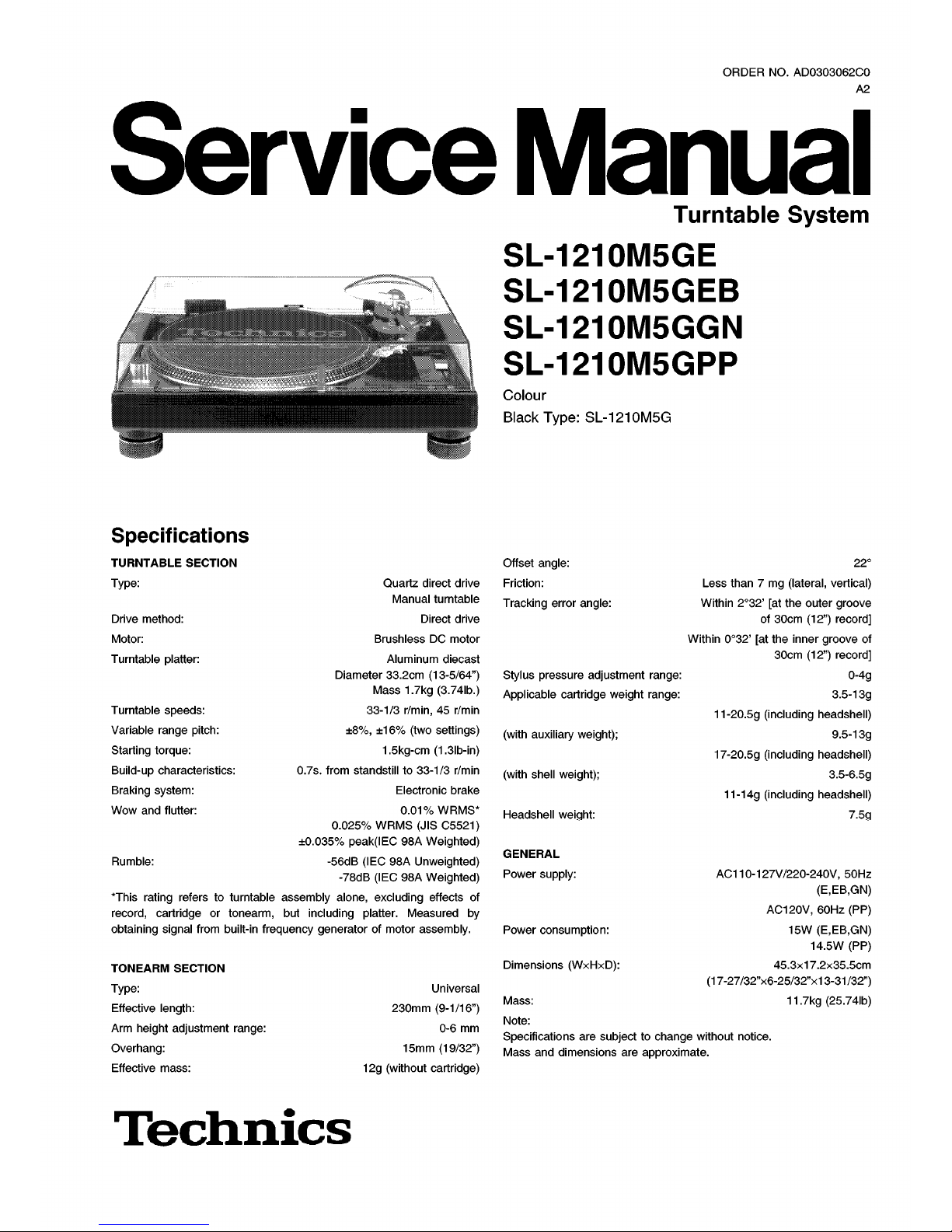
Turntable
System
SL
-
1210
M
5
GE
SL
-
1210
M
5
GEB
SL
-
1210
M
5
GGN
SL
-
1210
M
5
GPP
Colour
Black
Type
:
SL
-
1210
M
5
G
Specifications
TURNTABLE
SECTION
Type
:
Offset
angle
:
Friction
:
Tracking
errar
angle
:
22
°
Guartz
direct
drive
Manual
turntable
Direct
drive
Brushless
DC
motor
Aluminum
diecast
Diameter
33.2
cm
(
13
-
5
/
64
”
)
Mass
1.7
kg
(
3.74
lb
.
)
33
-
1
/
3
r
/
min
,
45
r
/
min
±
8
%
,
±
16
%
(
two
settings
)
1.5
kg
-
cm
(
1.3
lb
-
in
)
0.7
s
.
tram
standstill
to
33
-
1
/
3
r
/
min
Electronic
brake
0.01
%
WRMS
*
0.025
%
WRMS
(
JIS
C
5521
)
±
0.035
%
peak
(
IEC
98
A
Weighted
)
-
56
dB
(
IEC
98
A
Unweighted
)
-
78
dB
(
IEC
98
A
Weighted
)
*
This
rating
refers
to
turntable
assembly
alone
,
excluding
effects
of
record
,
cartridge
or
tonearm
,
but
including
platter
.
Measured
by
obtaining
signal
tram
built
-
in
frequency
generator
of
motor
assembly
.
Less
than
7
mg
(
lateral
,
vertical
)
Within
2
°
32
’
[
at
th
è
outer
groove
of
30
cm
(
12
”
)
record
]
Within
0
°
32
’
[
at
th
è
inner
groove
of
30
cm
(
12
”
)
record
]
0
-
4
g
3.5-13
g
11
-
20.5
g
(
including
headshell
)
9.5
-
13
g
17
-
20.5
g
(
including
headshell
)
3.5
-
6.5
g
11
-
14
g
(
including
headshell
)
Drive
method
:
Motor
:
Turntable
platter
:
Stylus
pressure
adjustment
range
:
Applicable
cartridge
weight
range
:
Turntable
speeds
:
Variable
range
pitch
:
Starting
torque
:
Build
-
up
characteristics
:
Braking
System
:
Wow
and
flutter
:
(
with
auxiliary
weight
)
;
(
with
shell
weight
)
;
Headshell
weight
:
7.5
g
GENERAL
Power
supply
:
Rumble
:
AC
110
-
127
V
/
220-240
V
,
50
Hz
(
E,EB
,
GN
)
AC
120
V
,
60
Hz(PP
)
15
W(E,EB
,
GN
)
14.5
W(PP
)
45.3
x
17.2
x
35.5
cm
(
17
-
27
/
32
”
x
6
-
25
/
32
”
x
13-31/32
”
)
11.7
kg
(
25.74
lb
)
Power
consumption
:
Dimensions
(
WxHxD
)
:
TONEARM
SECTION
Type
:
Effective
length
:
Arm
height
adjustment
range
:
Overhang
:
Effective
mass
:
Universal
230
mm
(
9
-
1
/
16
”
)
0-6
mm
15
mm
(
19
/
32
”
)
12
g
(
without
cartridge
)
Mass
:
Note
:
Specifications
are
subjecttochange
without
notice
.
Mass
and
dimensions
are
approximate
.
Techmcs

SL
-
1210
M
5
GE
/
SL
-
1210
M
5
GEB
/
SL
-
1210
M
5
GGN/SL
-
1210
M
5
GPP
A
WARNING
This
Service
information
is
designed
for
experienced
repair
technicians
only
and
is
not
designed
for
use
by
th
è
generai
public
.
It
does
not
contain
warnings
or
cautionstoadvise
non
-
technical
individuals
of
potential
dangersinattempting
to
Service
a
product
.
Products
powered
by
electricity
shouldbeserviced
or
repaired
only
by
experienced
professional
technicians
.
Any
attempt
to
Service
or
repair
th
è
productorproducts
dealt
with
in
this
Service
information
by
anyone
else
could
resultinserious
injury
or
death
.
CONTENTS
Page
Page
1
Accessories
2
Controls
3
Turntable
System
pitch
adj
.
slider
replacement
instructions
.
4
4
Safety
Precaution
5
Caution
for
AC
Mains
Lead
6
Operation
Checks
and
Component
Replacement
Procedures
7
6.1
.
Checking
for
th
è
main
P
.C.B.
and
power
supply
P
.
C
.B.
—
7
6.2
.
Checking
for
th
è
pitch
control
(1)
P
.C.B.
6.3
.
Replacement
for
th
è
drive
coil
ass
’
y
and
FG
coil
ass
’
y
—
•
9
6.4
.
Replacement
for
th
è
tonearm
unit
6.5
.
Replacement
for
th
è
parts
mounted
onspeed
selector
P
.C.
B
.
and
power
switch
6.6
.
Replacement
for
th
è
LED
and
Stylus
illuminator
switch
-
12
7
Cautions
in
handling
of
thèblue
LED
8
Type
lllustration
of
IC
’
s
,
Transistors
and
Diods
9
Measurements
and
Adjustments
9.1
.
The
stateofset
and
th
è
use
apparatus
9.2
.
Measurements
and
Adjustments
9.3
.
Alignment
points
10
Schematic
Diagram
10.1
.
Schematic
Diagram
Notes
10.2
.
Schematic
Diagram
11
Printed
Circuit
Board
Diagram
12
Block
Diagram
13
Wiring
Connection
Diagram
14
Replacement
Parts
List
15
Cabinet
Parts
Location
15.1
.
Cabinet
15.2
.
Tonearm
16
Packaging
2
15
3
15
15
5
15
6
16
16
17
8
19
21
10
22
23
12
27
27
14
28
14
29
1
Accessories
•
Disc
slip
sheet
set
(
RGS
0005
Z
-
1
)
.
.
.
1
pc
.
•
Overhang
gauge
(
SFK
0135
-
01
)
..
.
1
pc
.
Teclmics
SDYmioe
.i.
-
Disc
slip
sheet
-
Transparent
sheet
•
Auxiliary
weight
(
SFPWG
17202
)
..
.
1
pc
.
•
Nuts
(
RHN
26003
)
..
.
2
pcs
.
•
Screws
(
short
) (
SFCZV
8801
-
1
)
..
.
2
pcs
.
•
Screws
(
long
)
(
SFPEV
9801
-
1
)
..
.
2
pcs
.
•
Washers
(
SFPEW
9601
)
...
2
pcs
.
•
Sticker
(
RQLC
0142
-
1
)
.
.
.
1
pc
.
•
EP
record
adaptor
(
SFWE
010
A
)
...
1
pc
.
•
Shell
weight
(
SFPZB
3501
)
.
.
.
1
pc
.
2
SL
-
1210
M
5
GE
/
SL
-
1210
M
5
GEB
/
SL
-
1210
M
5
GGN
/
SL
-
1210
M
5
GPP
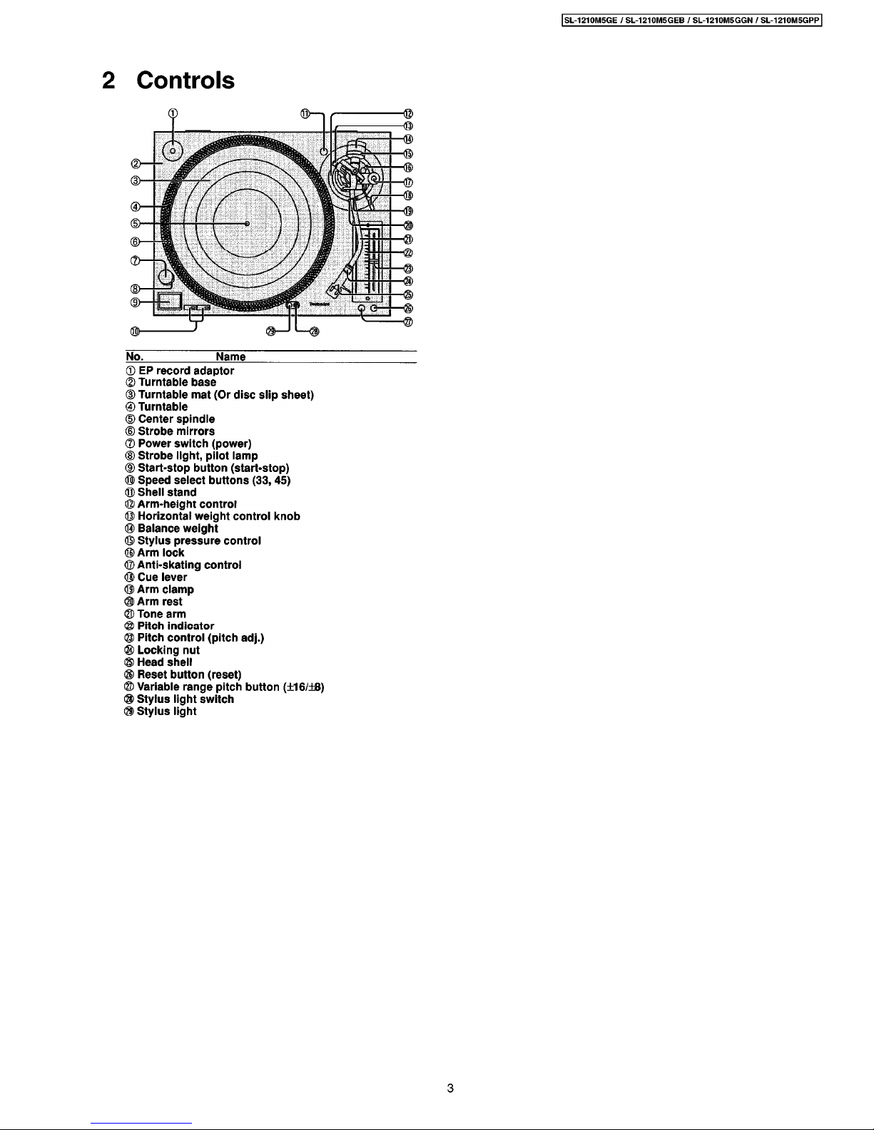
2
Controls
i
©
<S>
2
<
©
d
>
©
>
E
©
<
2
>
d
>
©
d
>
©
<g>
#
No
.
Name
©
EP
record
adaptor
©
Turntable
base
(
D
Turntable
mat
(
Or
disc
slip
sheet
)
®
Turntable
@
Center
spindle
®
Strobe
mirrors
®
Power
switch
(
power
)
®
Strobe
llght
,
pilot
lamp
CD
Start
-
stop
button
(
start
-
stop
)
®
Speed
select
buttons
(
33
,
45
)
®
Shell
stand
©
Arm
-
height
control
©
Horizontal
weight
control
knob
®
Balance
weight
©
Stylus
pressure
control
©
Arm
lock
©
Anti
-
skating
control
®
Cue
lever
®
Arm
clamp
©
Arm
rest
©
Tone
arm
®
Pitch
indicator
©
Pitch
control
(
pitch
adj
.
)
®
Locking
nut
©
Head
Shell
®
Reset
button
(
reset
)
@
Variable
range
pitch
button
(
±
16
/
±
8
)
®
Stylus
light
switch
©
Stylus
light
3
SL
-
1210
M
5
GE
/
SL
-
1210
M
5
GEB
/
SL
-
1210
M
5
GGN/SL
-
1210
M
5
GPP
3
Turntable
System
pitch
adj
.
slider
replacement
instructions
.
®
B
.
4
m
5.1
2
i
3
vi
:
:
i
i
1
4
Ì
'
?
!
il
V.V
:
fi
il
?
1
•
1
'
:
ì
.
V
i
il
!
f
I
:
:
%
Hi
I
2
i
'
y
.
t
li
:
K
2
i
&
Si
555
HH
;
Ì
.
-
VV
.
5
,
’
H
-
,
,
-
.
H
,
-V-
|
i
-
HVHHHHH
'
i
'
iiiHrH
Hii
:
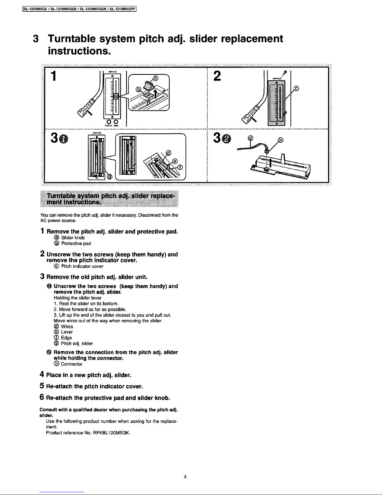
Turntable
System
pitch
adj
.
slider
replace
-
ment
instructions
.
You
can
remove
th
è
pitch
adj
.
slider
if
necessary
.
Disconnect
tram
th
è
AC
power
source
.
1
Remove
th
è
pitch
adj
.
slider
and
protective
pad
.
©
Slider
knob
(
B
)
Protective
pad
2
Unscrew
th
è
two
screws
(
keep
them
handy
)
and
remove
th
è
pitch
indicator
cover
.
©
Pitch
indicator
cover
3
Remove
th
è
old
pitch
adj
.
slider
unit
.
Unscrew
th
è
two
screws
(
keep
them
handy
)
and
remove
th
è
pitch
adj
.
slider
.
Holding
th
è
slider
lever
1
.
Rest
th
è
slideronits
bottom
.
2
.
Move
forward
as
far
as
possible
.
3
.
Lift
up
th
è
end
of
th
è
slider
closest
to
you
and
pul
ì
out
.
Move
wires
out
of
th
è
way
when
removing
th
è
slider
.
©
Wires
©
Lever
©
Edge
©
Pitch
adj
.
slider
Remove
thèconnection
from
th
è
pitch
adj
.
slider
while
holding
th
è
connector
.
©
Connector
4
Place
in
a
new
pitch
adj
.
slider
.
5
Re-attach
th
è
pitch
indicator
cover
.
6
Re
-
attach
th
è
protective
pad
and
slider
knob
.
Consult
with
a
qualified
dealer
when
purchasing
th
è
pitch
adj
.
slider
.
Use
th
è
following
product
number
when
asking
for
th
è
replace
-
ment
.
Product
reference
No
.
RFKBL
120
M
5
GK
.
4
SL
-
1210
M
5
GE
/
SL
-
1210
M
5
GEB
/
SL
-
1210
M
5
GGN
/
SL
-
1210
M
5
GPP
4
Safety
Precaution
(
This
“
Safety
Precaution”is
applied
only
in
U
.S.A.
)
1
.
Before
servicing
,
unplug
th
è
power
cord
to
prevent
an
electric
shock
.
2
.
When
replacing
parts
,
use
only
manufacturer
’
s
recommended
components
for
safety
.
3
.
Check
th
è
condition
of
th
è
power
cord
.
Replace
if
wear
or
damage
is
evident
.
4
.
After
servicing
,
be
sure
to
restore
th
è
lead
dress
,
insulation
barriers
,
insulation
papers
,
shields
,
etc
.
5
.
Before
returning
th
è
serviced
equipment
to
th
è
customer
,
be
sure
to
make
th
è
following
insulation
resistance
test
to
prevent
th
è
customer
from
being
exposed
to
a
shock
hazard
.
Insulation
Resistance
Test
1
.
Unplug
th
è
power
cord
and
short
th
è
two
prongs
of
th
è
plug
with
a
jumper
wire
.
2
.
Turn
on
th
è
power
switch
.
3
.
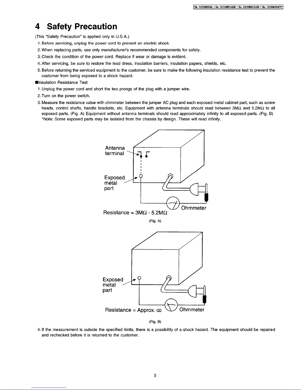
Measure
th
è
resistance
value
with
ohmmeter
between
th
è
jumper
AC
plug
and
each
exposed
metal
cabinet
part
,
such
as
screw
heads
,
control
shafts
,
handle
brackets
,
etc
.
Equipment
with
antenna
terminals
should
read
between
3
M
£
2
and
5.2
M
&
to
all
exposed
parts
.
(
Fig
.
A
)
Equipment
without
antenna
terminals
should
read
approximately
infinity
to
all
exposed
parts
.
(
Fig
.
B
)
*
Note
:
Some
exposed
parts
may
be
isolated
from
th
è
chassis
by
design
.
These
will
read
infinity
.
Antenna
terminal
/
2
o
Exposed
metal
-
Zt
part
Ohmmeter
Resistance
=
3
MQ
-
5.2
MQ
(
Fig
.
A
)
*
9
Exposed
metal
-
part
Ohmmeter
Resistance
=
Approx
.
oo
(
Fig
.
B
)
4
.
If
th
è
measurement
is
outside
th
è
specified
limits
,
there
is
a
possibility
of
a
shock
hazard.The
equipment
should
be
repaired
and
rechecked
before
it
is
returned
to
th
è
customer
.
5
SL
-
1210
M
5
GE
/
SL
-
1210
M
5
GEB
/
SL
-
1210
M
5
GGN/SL
-
1210
M
5
GPP
5
Caution
for
AC
Mains
Lead
WARNING:DO
NOT
CONNECT
EITHER
WIRETOTHE
EARTH
TERMINAL
WHICH
IS
MARKED
WITH
THE
LETTER
E,BY
THE
EARTH
SYMBOL
OR
COLOURED
GREENORGREEN/YELLOW
.
(
For
United
Kingdom
)
(
“
EB
”
area
code
model
only
)
Foryour
safety
,
please
read
th
è
following
text
carefully
.
THIS
PLUG
IS
NOT
WATERPROOF
—
KEEP
DRY
.
This
appliance
is
supplied
with
a
moulded
three
pin
mains
plug
for
your
safety
and
convenience
.
A
5
-
ampere
fuse
is
fitted
in
this
plug
.
Should
th
è
fuse
needtobe
replaced
please
ensure
that
th
è
replacement
fuse
has
a
rating
of
5
-
ampere
and
that
it
is
approved
by
ASTAorBSI
to
BS
1362
.
Check
for
th
è
ASTA
mark
<
^
>
or
th
è
BSI
mark
^
on
th
è
body
of
th
è
fuse
.
Before
use
Remove
th
è
connector
cover
.
How
to
replace
th
è
fuse
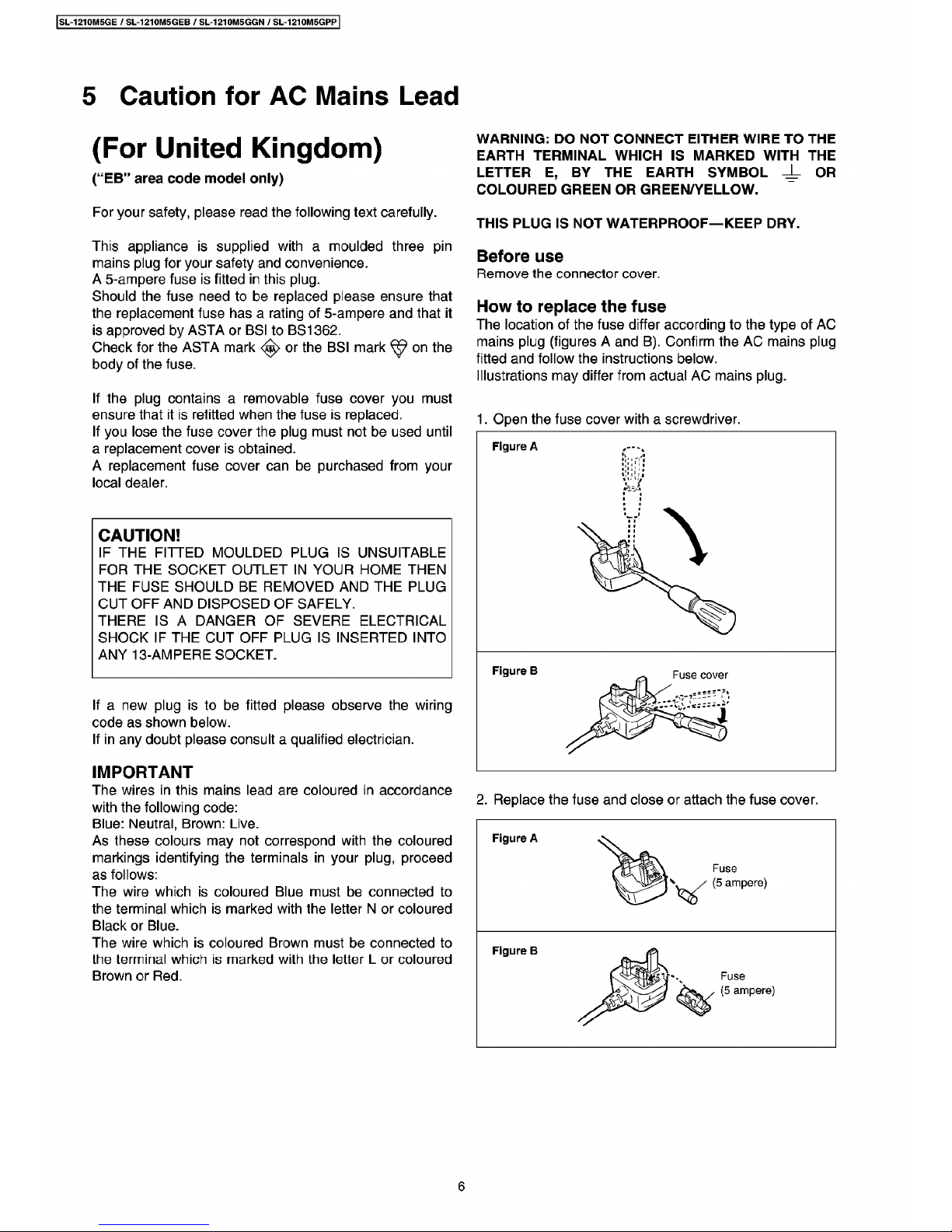
The
location
of
th
è
fuse
differ
according
to
th
è
type
of
AC
mains
plug
(
figures
A
and
B
)
.
Confirm
th
è
AC
mains
plug
fitted
and
follow
th
è
instructions
below
.
Illustrations
may
differ
from
actual
AC
mains
plug
.
If
th
è
plug
containsaremovable
fuse
cover
you
must
ensure
that
it
is
refitted
when
th
è
fuse
is
replaced
.
If
you
lose
th
è
fuse
cover
th
è
plug
must
not
be
used
until
a
replacement
cover
is
obtained
.
A
replacement
fuse
cover
can
be
purchased
from
your
locai
dealer
.
1
.
Open
th
è
fuse
cover
with
a
screwdriver
.
CAUTION
!
IF
THE
FITTED
MOULDED
PLUG
IS
UNSUITABLE
FOR
THE
SOCKET
OUTLET
IN
YOUR
HOME
THEN
THE
FUSE
SHOULDBEREMOVED
AND
THE
PLUG
CUT
OFF
AND
DISPOSED
OF
SAFELY
.
THERE
ISADANGER
OF
SEVERE
ELECTRICAL
SHOCK
IF
THE
CUT
OFF
PLUG
IS
INSERTED
INTO
ANY
13
-
AMPERE
SOCKET
.
If
a
new
plug
istobe
fitted
please
observe
th
è
wiring
code
as
shown
below
.
If
in
any
doubt
please
consult
a
qualified
electrician
.
IMPORTANT
The
wires
in
this
mains
lead
are
coloured
in
accordance
with
th
è
following
code
:
Blue:Neutral
,
Brown:Live
.
As
these
colours
may
not
correspond
with
th
è
coloured
markings
identifying
th
è
terminals
in
your
plug
,
proceed
as
follows
:
The
wire
whichiscoloured
Blue
must
be
connected
to
th
è
terminal
whichismarked
with
th
è
letter
N
or
coloured
Black
or
Blue
.
The
wire
which
is
coloured
Brown
must
be
connected
to
th
è
terminal
whichismarked
with
th
è
letter
L
or
coloured
Brown
or
Red
.
2
.
Replace
th
è
fuse
and
doseorattach
th
è
fuse
cover
.
Figure
A
6
SL
-
1210
M
5
GE
/
SL
-
1210
M
5
GEB
/
SL
-
1210
M
5
GGN
/
SL
-
1210
M
5
GPP
6
Operation
Checks
and
Component
Replacement
Procedures
•
This
section
describes
procedures
for
checking
th
è
operation
of
th
è
major
printed
Circuit
boards
and
replacing
th
è
main
components
.
•
For
reassembly
after
operation
checks
or
replacement
,
reverse
th
è
respective
procedures
.
Special
reassembly
procedures
are
described
only
when
required
.
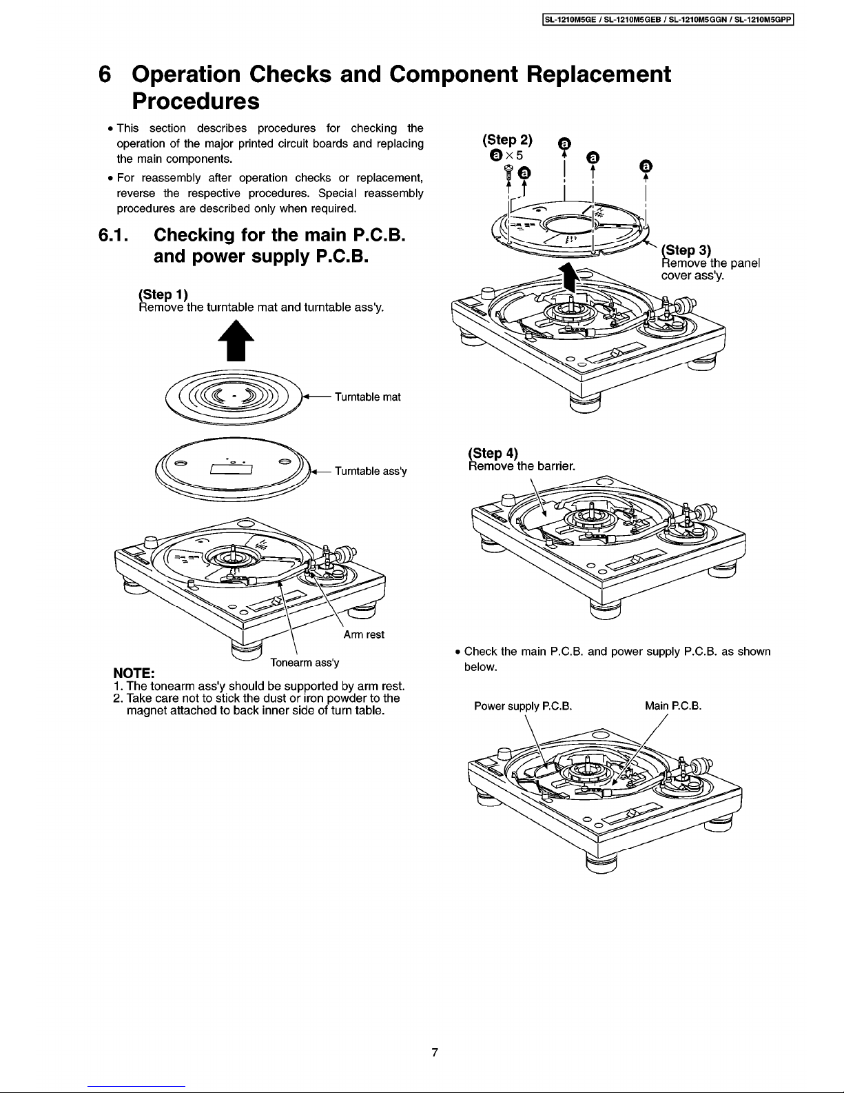
(
Step
2
)
©
x
5
o
t
©
©
t
©
t
/
il
(
;
=
-
=
-
Checking
for
thèmain
P
.C.B.
and
power
supply
P
.C.B.
6.1
.
fi
'
(
Step
3
)
Remove
th
è
panel
cover
ass
'
y
.
(
Step
1
)
Remove
th
è
turntable
mat
and
turntable
ass
'
y
.
&
o
Turntable
mat
<
(
Step
4
)
Remove
th
è
barrier
.
&
Turntable
ass
'
y
&
%
Arm
rest
•
Check
th
è
main
P
.C.B.
and
power
supply
P
.C.B.
as
shown
below
.
Tonearm
ass
'
y
NOTE
:
1
.
The
tonearm
ass
'
y
should
be
supported
by
arm
rest
.
2
.
Take
care
not
to
stick
th
è
dustoriron
powder
to
th
è
magnet
attachedtoback
inner
side
of
turn
table
.
Power
supply
P
.C.
B
.
Main
P
.
C
.B.
7
SL
-
1210
M
5
GE
/
SL
-
1210
M
5
GEB
/
SL
-
1210
M
5
GGN/SL
-
1210
M
5
GPP
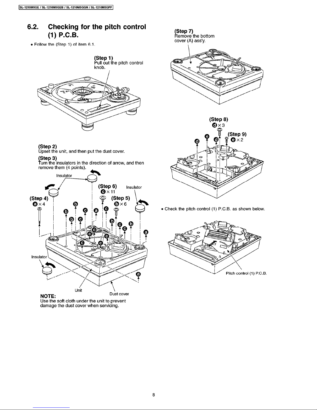
6.2
.
Checking
for
th
è
pitch
control
(1)
P
.C.B.
(
Step
7
)
Remove
th
è
bottom
cover
(A)
ass
'
y
.
•
Follow
th
è
(
Step
1
)
of
item
6.1
.
(
Step
1
)
Pul
ì
out
th
è
pitch
control
knob
.
(
Step
8
)
©
x
3
(
Step
9
)
©
x
2
(
Step
2
)
Upset
th
è
unit,and
then
put
th
è
dust
cover
.
(
Step
3
)
Turn
th
è
insulators
in
th
è
direction
of
arrow
,
and
then
remove
them
(
4
points
)
.
Insulator
(
Step
6
)
©
X
11
Insulator
S
>
(
Step
5
)
(
Step
4
)
©
X
4
•
Check
th
è
pitch
control
(1)
P
.C.
B
.
as
shown
below
.
<
&
<o>
fe
.
4
Insulator
Pitch
control
(
1
)
P
.
C
.
B
.
Dust
cover
NOTE
:
Use
th
è
soft
cloth
under
th
è
unit
to
prevent
damage
th
è
dust
cover
when
servicing
.
8
SL
-
1210
M
5
GE
/
SL
-
1210
M
5
GEB
/
SL
-
1210
M
5
GGN
/
SL
-
1210
M
5
GPP
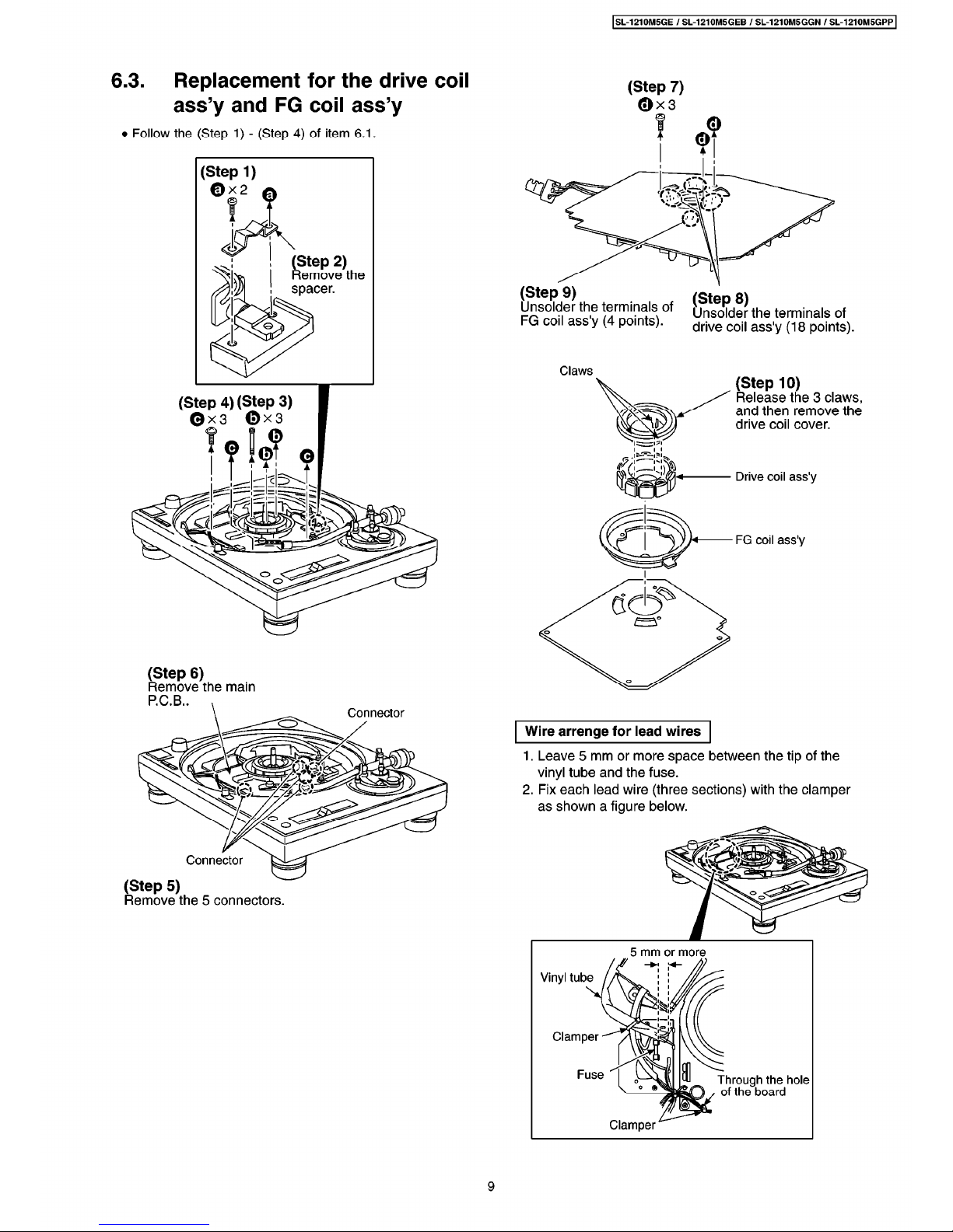
6.3
.
Replacement
for
thèdrive
coil
ass
’
y
and
FG
coil
ass
’
y
•
Follow
th
è
(
Step
1
)-(
Step
4
)
of
item
6.1
.
(
Step
7
)
0
x
3
(
Step
1
)
0
x
2
7
(
Step
2
)
Re
move
th
è
spacer
.
(
Step
9
)
Unsolder
th
è
terminals
of
FG
coil
ass
'
y
(
4
points
)
.
(
Step
8
)
Unsolder
th
è
terminals
of
drive
coil
ass
'
y
(
18
points
)
.
Claws
(
Step
10
)
Release
th
è
3
claws
,
and
then
remove
th
è
drive
coil
cover
.
(
Step
4
)
(
Step
3
)
©
x
3
0
x
3
Drive
coil
ass
'
y
FG
coil
ass
'
y
(
Step
6
)
Remove
th
è
mairi
P
.C.B.
.
Connector
Wire
arrenge
for
lead
wires
1
.
Leave
5
mirri
or
more
space
between
th
è
tip
of
th
è
vinyl
tube
and
th
è
fuse
.
2
.
Fix
each
lead
wire(three
sections
)
with
th
è
damper
as
shown
a
figure
below
.
Connector
(
Step
5
)
Remove
th
è
5
connectors
.
9
 Loading...