

Page 1
ORDER
NO.SD7908-1601
Service
Manual
service
This
andisnot
only
contain
potential
by
electricity
professional
or,,products
in..serious
rest''
SL-12
A
WARNING
designed
literature
warnings
dangers
technicians.C
dealt
"
*The
is
designed
cau:'.ons
or
in
attempting
should
with
injuryordeath
The
model
model
be
in
SL-11
SL-1200MK2
for
use
to
to
serviced
attempt
.iy
service
this
.
200MK2
Turntable
OM
(M),
experienced
for
the
general
by
non-technical
advise
a
service
repaired
or
to
service
literature
(M)isavailableinU.S.A.only
(MC)
repair
public
.
Products
product
only
or
repair
anyone
t
;+
is
availableinCanada
by
System
K2
(MC)
technicians
It
does
.
individuals
powered
experienced
the
product
could
else
not
of
only
.
.
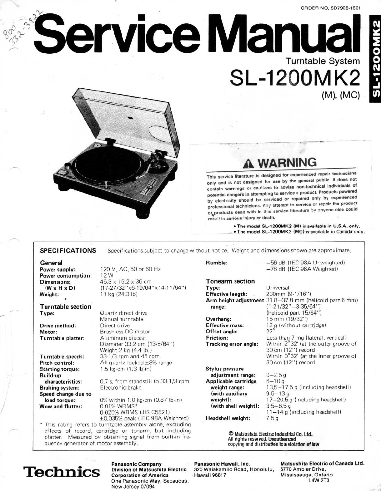
SPECIFICATIONS
General
supply
Power
Power
Dimensions
(WxHxD)
Weight
Turntable
Type
:
Drive
Motor
Turntable
Turntablespeeds
Pitch control
;
:carting
Build-up
characteristics
Braking
Speed
load
Wow
and
*
This
effects
platter.Measuredby
quency
:
consumption
:
:
section
method
:
:
platter
:
:
:
torque
:
:
system
:
change
due
torque
:
flutter
:
rating
refers
of record,
generatorofmotor
Specifications subject to
120
V,AC,50or60Hz
:
12W
45
.3x16.2
(17-27/32"x6-19/64"xl4-11/64")
11
kg (24.3lb)
Quartz
Manual
Direct
BrushlessDCmotor
Aluminum
Diameter33.2cm(13-5/64")
Weight
33-1/3
All
quartz-locked
1.5kg-cm(1.3
0
.7 s.from
Electronic
to
0%
within1.0
0
.01%
0
.025%
±0
.035%
to turntable
cartridge
obtaining
x36
direct
drive
turntable
drive
diecast
2 kg(4.4 lb
rpm
and
Ib-in)
standstillto33-1/3
brake
kg-cm
WRMS*
WRMS
assembly
peak
assembly
or
tonarm,
signal
(JIS
(IEC
.
cm
45
±8%
from
.)
rpm
(0
C5521)
98A
alone,
but
range
Ib-in)
.87
Weighted)
excluding
including
built-in
change
rpm
fre-
without
notice
.
Rumble
:
Tonearm
Type
:
Effective
Arm
height
range
:
Overhang
Effective
Offset angle
Friction
Tracking
Stylus
Applicable
Headshell
:
pressure
adjustment
weight
(with
auxiliary
weight)
(with
shell
Cud
All
copying
Weight
and
section
length
:
adjustment
:
mass
:
:
error angle
range
cartridge
range
:
:
weight):3
weight
:
Matsushita
rights
reserved
and
dimensions
-56
dB(IEC
-78
dB
Universal
230mm
31
.8-37.8mm
(1-21
/32"-3-35/64")
(helicoid
15
mm
12 g
(without
22
°
Less
than7mg
Within2°
:
30
cm
(12") record
Within0°
cm
(12") record
30
:
0-2.5g
g
6-10
13
.5-17
9
.5-13
17-20.5g
.5-6.5g
11-14g(including
7.5g
Electric
Industrial
.
Unauthenzed
distribution
is
a
shown
are
98A
Unweighted)
(IEC
98A
Weighted)
(9-1/16")
(helicoid
part
15/64")
(19/32")
cartridge)
(lateral,
the
32'
(at
32'
the
(at
.5g(including
g
(including
Co.Ltd
.
violation
of
law
approximate
part6mm)
vertical)
outer
groove
inner
groove
headshell)
headshell)
headshell)
.
of
of
Panasonic
DivisionofMatsushita
CorporationofAmerica
One
New
Company
Panasonic
Jersey
Way,
07094
Electric
Secaucus,
Panasonic
320
Waiakamilo
.Hawaii
96817
Hawaii,
Inc
Road,
.
Honolulu,
Matsushita
5770
Ambler
Mississauga,
ElectricofCanada
Drive,
Ontario
LAW
2T3
Ltd
.
Page 2
SL-1200MK2
CONTENTS
DISASSEMBLY
PARTS
IDENTIFICATIONS
ARM
BASE
FEATURES
ADJUSTMENTS
SCHEMATIC
REPLACEMENT
TROUBLE
SHOOTING
PROCEDURE
ASSEMBLING
.
. . ..... . . . . . . . . . . . . ... . . . ... . . . . . . . . ...
. ..... . . . . . . . . . . ... . ... . . . . . . . . . . ...6
DIAGRAM
PARTS
. ... . ..... . . . . . . . . . . . . . . .
. . . ... . . . ... . . . . . . . . . . . . . . .3
PROCEDURE.. . ... . . . . ... . ...4
.
... . . .
LIST
. ....... . . . . . . ... . . . . . . . . . . . . .10
. . . . ...
. . .
(Electrical)
. . . . . . . .
..... . . . . . . . . ...9
. . .
2,3
5
7,8
PRINTED
ADJUSTMENT
REFERENCE
PIN
. . . . . . . . .
BLOCK
DIAGRAM.. . ... . . . . . . . . . . . . ..... . ... . . . . .
EXPLODED
REPLACEMENT
EXPLODED
CIRCUIT
BOARD
(Electrical)
VOLTAGE
...
. ... . . . . . . . . . ... . . . ... . . . . . . . . .
VIEWS.. . . . . . . . . . . . . . . . . . . ..... . . . . . . .
PARTS
VIEWS
. . ... . ... . . . . ... . ..... . . . . . . . . .20
. . . . . . . . ....... . . . . . . . . .
. . . . . . . . . .
AND
WAVEFORM
LIST
(Mechanical)
......... . . . . . . .
AT
. ... . . . . . . . . .19
EACH
11,12
13
IC
13,14
15,16
17,18
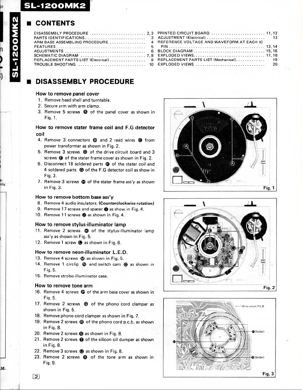
DISASSEMBLY
How
to
remove
1.Remove
2.Secure
3.Remove5screws
Fig
. 1
.
How
to
remove
coil
4.Remove
power
transformerasshown
5.Remove3screws
screws©of
6.Disconnect
4
soldered
Fig.3
.
7.Remove3screwsQof
in
Fig.3
How
to
remove
8.Remove
9.Remove
10.Remove
How
to
remove
11.Remove
ass'yasshowninFig.5
12.Remove1screwOas
panel
head
shell
and
arm
with
arm
O
stater
3
connectorsOand
@
the
stater
18
soldered
parts
OoftheF.G detector
.
bottom
4
audio
insulators.(Counterclockwise
17
screws
and
11
screwsOas
stylus-illuminator
2
screws
PROCEDURE
cover
turntable
clamp
.
of
the
panel coverasshown
frame
Q
coil
in
of
the
drive
frame
coverasshowninFig.2
partsOof
the
stater
base
ass'y
spacerQas
shown
of
the
.
showninFig.6
.
2
read
Fig.2
frame
andF.G
.
circuit
the
detector
wires@from
board
and
stater
coil
coil as
show
ass'yasshown
rotation)
showinFig.4
in
Fig.4
.
.
lamp
stylus-illuminator
.
in
3
.
and
in
lamp
How
to
remove
13.Remove4
14.Remove1circlip
Fig.5
.
15.Remove
How
to
remove
16.Remove4screws
Fig.5
.
17.Remove
showninFig
18.Remove
19.Remove
in
Fig
.
neon-illuminatorL.E.D.
screwsQas
Q
strobo-illuminator
tone
arm
Q
2
screws
phono
2
screwsQof
8
.
©
.
5
.
cord
clamperasshowninFig.7
20.Remove2screws©as
21.Remove2screwsQof
in
Fig.8
.
22.Remove3screwsQas
23
.
Remove
Fig
2
screws
.
9
.
0
showninFig.5
and
switch
case
.
of
the
arm
base
of
the
phono
the
phono
shown
in
the
silicon
showninFig.8
of
the
tone
.
cam
as
shown
QQ
coverasshown
cord
clamper
.
cordp.c.b.asshown
Fig.8
.
oil
dumperasshown
.
arm
as
shown
in
in
as
in
Page 3
Lamp
caset
Fig
.
Fig
9
.
m
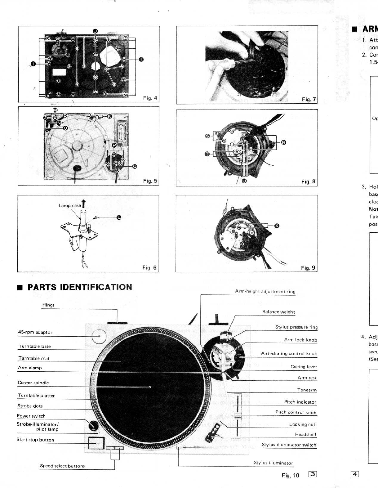
PARTS
Hinge
Power
switch
Strobe-illuminator/
pilot
Speed
lamp
IDENTIFICATION
select
buttons
Arm-height
adjustment
Balance
ring
weight
Fig.10
10
Page 4
.
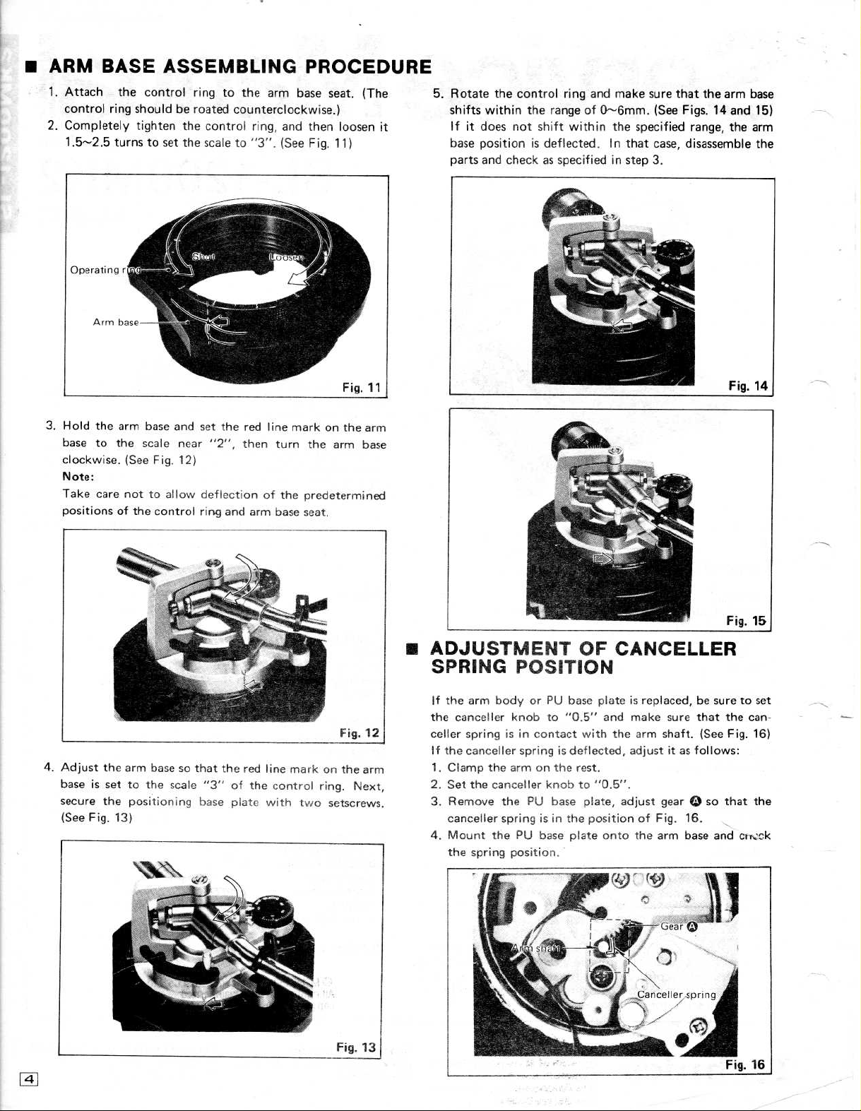
ARM
1.Attach
2.Completely
control
1
.5---2 .5
BASE
the control
ring
shouldberoated
tighten
turns to
ASSEMBLING
ring
to the
counterclockwise
the
control
set
the
scaleto"3".(See Fig.11)
ring,
PROCEDURE
arm
base
and
seat.(The
.)
then
loosen
5.Rotate
shifts
it
base
parts
the control
within
the
rangeof0-6mm.(See Figs.14
If it
not
does
positionisdeflected.In
and
shift
checkasspecifiedinstep 3
ring
within
and
make
the
that
sure
specified
case,
.
that the
range,
disassemble
arm
and
the
base
15)
arm
the
3.Hold
4.Adjust
the
base to the
clockwise
Note
:
Take
care
positions
baseissettothe
secure
(See
of
the
the
Fig.13)
arm
base
scale
.
(See Fig.12)
not
to allow
the
control
arm
base
positioning
and
near
so
scale
set
the
"2", then
deflection
ring
and
that the
"3"
of the
base
plate
red
red
arm
line
turn the
of the
base
line
control
with
markon
arm
predetermined
seat
.
mark
on
ring.Next,
two
setscrews
the
base
Fig.12
the
arm
arm
®
ADJUST
SPRING
If
the
arm
the
canceller
celler
springisin
if
the
canceller
1.Clamp
2.Set
the
.
3.Remove
canceller
4.Mount
the
spring
ENT
POSITION
body
or
PU
knob
to"0.5"
contact
springisdeflected,
the
armonthe
canceller
the
springisin
the
PU
PU
base
position
knobto"0
OF
base
plateisreplaced,besure to
and
with
rest
.
.5"
base
plate,
the
positionofFig.16
plate
onto
.
CANCELLER
make
sure that the can-
the
arm
shaft.(See Fig.16)
adjustitas
.
adjust gearQso that the
the
arm
follows
.
base
and
:
cit~ck
set
4
Page 5
FEATURES
Total
f8%
Quartz-phase-locked
of
But
circuit
With
tinuously
locked
lever,
+6%,+3.3%,
from
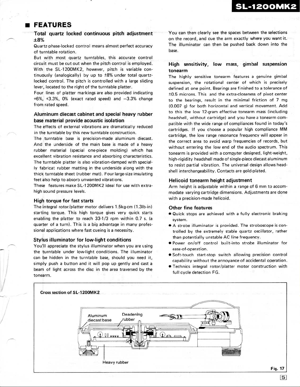
Aluminum
base
The
The
And
rubber
excellent
The
ly
thick turntable sheet
feet also
Thesefeatures
high
High
The
starting
enabling
quarterofa
sional
Stylus
You'll
the
canbehiddeninthe
simply
beam
tonearm
quartz locked
turntable
with
mustbecut
the
control
located
Four
linesofplatter
rated
material
effects
in
the turntable
turntable
the
material
turntable
fabricat
help to
sound
torque
integral
torque.This
the
applications
illuminator
appreciate
turntable
pushabutton
of
.
rotation
most
quartz
out
SL-1200MK2,
(analogically)
The
.
to
the
0%
(exact
speed
.
diecast
provide
of external
this
by
baseisprecision-made
undersideofthe
(special
vibration
rubber
pressure
light
resistance
platterisalso
mattinginthe
absorb
make
for
fast
rotor/platter
plattertoreach
turn).Thisisa
where
the
under
across
continuous
control
.
turntables,
when
however,
by
pitch
right
of
markings
rated
cabinet
acoustic
vibrations
new
(rubber
unwanted
SL-11
200MK2
levels
.
starts
motor
high
fast
for
low-light
stylus
low-light
turntable
anditwill
the
discinthe
adjustment
pitch
means
almost
perfect
this
accurate
the
pitch
controlisemployed
pitchisvariable
up
to
±8%
under
total
controlled
is
turntable
the
are
speed)
and
turntable construction
main
one-piece
and
vibration-damped
mat).Four
delivers1.5kg-cm(1.3lb-in)
torque
33-1/3
big
cueingisa
illuminator
conditions.The
provided
also
and
special
isolation
are
dramatically
baseismade
molding)
absorbing
underside along
vibrations
ideal
gives
rpm
advantageinmany
conditions
base,
should
popupgently
area
large
with
a
platter
-3
.3%
heavy
aluminum
characteristics
with
large-size
.
for
use
very
quick
within0.7s.
necessity
when
you
you
traversedbythe
accuracy
control
con-
quartz-
sliding
.
indicating
change
rubber
reduced
.
diecast
ofaheavy
which
with
illuminator
has
special-
with
the
insulating
extra-
starts
profes-
.
are
using
need
it,
and
cast
(a
a
SL-1200MK2
You
can
on the
illuminator
The
base
.
.
.
.
High
tonearm
The
highly
suspension,
definedatone
microns.This
±0
.5
to
the
(0
.007
to
this
headshell,
patible
cartridges.If
cartridge,
the
correct
without
tonearmisprovided withacomputer
high-rigidity
to
resist
shell
interchangeability.Contacts
Helicoid
Arm
heightisadjustable
modate
withaprecision-made
Other
"
Quick
system
"Astrobe
trolledbythe
than
Power
ease-of-operation
Soft-touch
capability
"
Technics
full
cycle
clearly
then
record,
sensitivity,
sensitive
the
bearings,
g)
for
both
the
low 12-gram
without
with
the
you
the
low
area to
entering
headshell
partial
tonearm
varying
fine features
stops
.
illuminatorisprovided.The
potentially
on/off
start-stop
without
integral
detectionFG.
see
the spaces
and
cue the
can
then
low
tonearm
rotational
Bearings
point
.
and
the
resultinthe
horizontal
effective
cartridge)
wide
rangeofcompliances
choose a
range
resonance
avoid
warp
the
low
endofthe
madeofsingle-piece diecast
vibration.The
height
withinarangeof6
cartridge
are
extremely
control
dimensions.Adjustments
helicoid
achieved
unstableACline
built-into
.
switch
the
annoyanceofaccidental
rotor/platter
between
arm
exactly
be pushed back
mass,
featuresagenuine
center
are
extra-closeness of
minimal
and
and
popular
frequencies
universal
adjustment
.
withafully
stable
allowing
where
gimbal
of
whichisprecisely
finishedtoa
vertical
tonearm
you
haveatonearm
high
frequency
audio spectrum
designed,
design allows
are
gold-plated
electronic
stroboscopeiscon-
quartz
frequency
strobe
motor
construction
the
selections
you
wantit.
down
into
suspension
gimbal
tolerance
pivot
frictionof7
movement.Add
mass
(including
in
found
compliance
of
oscillator,
illuminator
precision
today's
will
appear
records,
light-weight,
aluminum
.
mmtoaccom-
are
braking
.
control
operation
the
of
center
mg
com-
MM
in
but
.
This
head-
done
rather
for
with
.
Page 6
)MK2
lections
wantit.
nto
the
~ension
gimbal
recisely
of
-
ance
t
center
f7
mg
nt.Add
icluding
m
com-
today's
ice
MM
in
)pear
As,
but
m.This
weight,
iminum
vs
head-
accomre
done
braking
is
con-
,
rather
for
itor
control
eration
)n
with
SL-1200MK2
ADJUSTMENTS
for
fre-
.
and
the
into
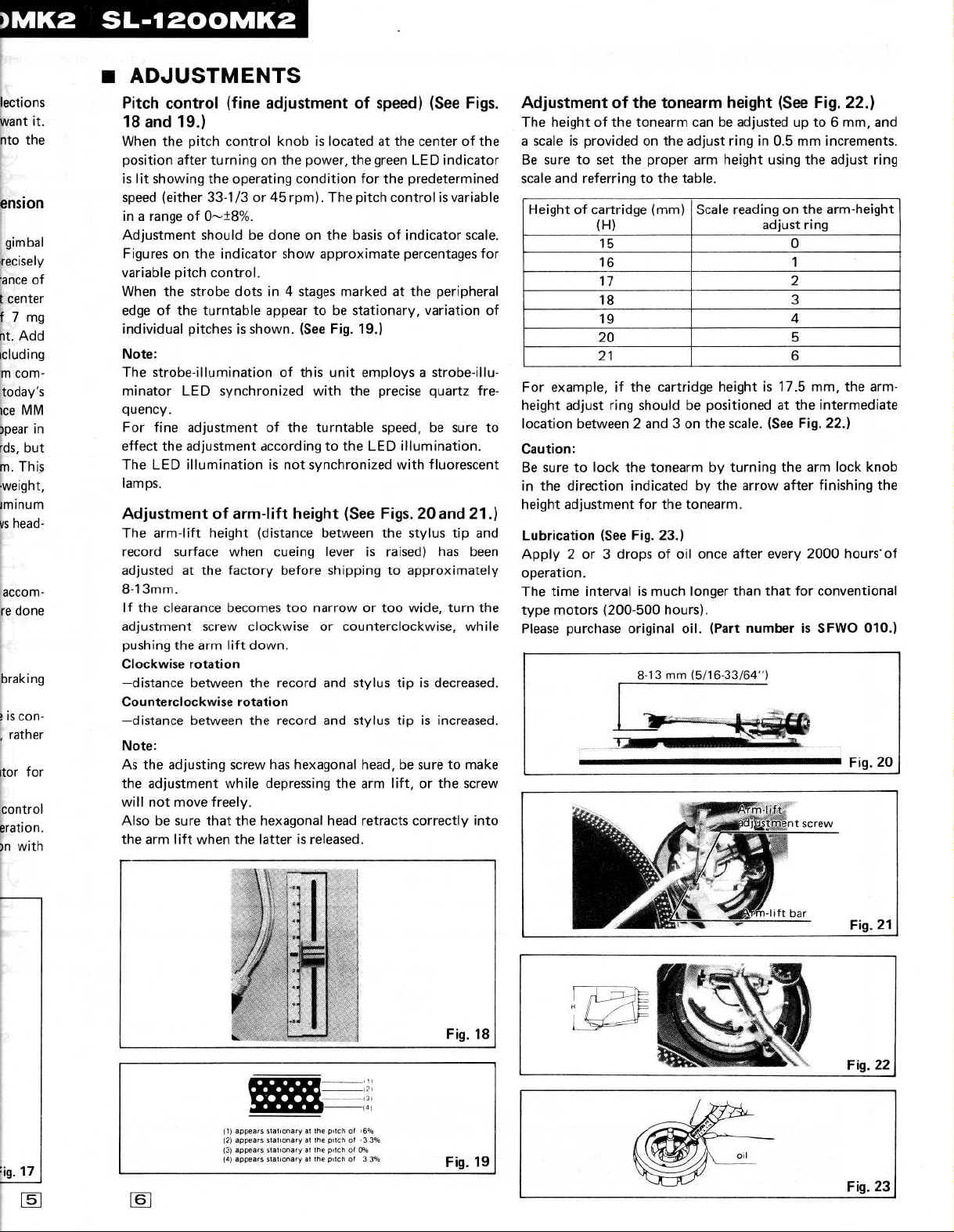
Adjustment
.
The
a
scaleisprovidedonthe adjust
Be
sure to
scale
Heightofcartridge
.
of
For
height
location
Caution
Be
sure to
in
the
height
.)
Lubrication
Apply
operation
The
typemotors
Please
.
.
height of the
and
example,ifthe
time
Pitch
control
18
and
19
When
the
position
is
speed
in a
lit
showing
range of
after
(either
Adjustment
Figuresonthe
variable
When
edge
pitch control
the strobe dotsin4
of the turntable
individual
Note
:
The
strobe-illumination of
minator
quency
.
For
fine
effect
the
The
LED
lamps
.
Adjustment
The
arm-lift
record
surface
adjustedatthe
8-13mm
If
.
the clearance
adjustment screw
pushing
the
Clockwise
-distance
Counterclockwise
-distance
Note
:
As
the adjusting
the
adjustment
will
not
move
.
Alsobesure that the
the
arm
lift
(fine
adjustment
.)
pitch
control
knobislocatedatthe
turningonthe power,
the
operating
33-1/3or45
0-±8%
condition
rpm).The
.
shouldbedone
indicator
show
.
stages
appeartobe
pitchesisshown.(See
LED
synchronized
adjustment
adjustment
illumination
of
height
of
accordingtothe
is
arm-lift
(distance
when
cueing
factory
becomes
the
not synchronized
height
before
too
clockwise
arm
lift
down
.
rotation
between
the
record
rotation
between
screw
while
freely
the
record
has
depressing
.
hexagonal
hexagonal
when
the
latterisreleased
of
speed)
center of the
on
the
approximate
marked
the green
for
pitch
basisofindicator
LED
the
predetermined
controlisvariable
percentages
at the
stationary,
Fig.19
.)
this
unit
employsastrobe-illu-
with
the
precise
turntable
speed, be sure to
LED
illumination
with
(See
Figs.20
between
the
stylus tip
leverisraised)
shippingtoapproximately
narrow
or
too
wide,
or
counterclockwise, while
and
stylus
tipisdecreased
and
stylus
tipisincreased
head,
be sure to
the
arm
lift,orthe
head
retracts
correctly
.
(See
Figs
indicator
scale
peripheral
variation
quartz
fluorescent
and
21
has
been
turn
make
screw
ofthe
tonearm
tonearm
set
the
proper
referringtothe
(mm)
(H)
15
16
17
18
19
20
21
cartridge
adjust
ring
shouldbepositionedatthe
between2and3on
:
lock
the
tonearm
direction
adjustment
indicatedbythe
for the
(See
Fig.23
.)
2 or3dropsofoil
.
intervalismuch
(200-500
purchase
hours)
original
height
(See
Fig.22
canbeadjustedupto6mm,
ringin0.5mm
arm
height using the
table
.
Scale readingonthe
adjust
increments
arm-height
ring
0
1
2
3
4
5
heightis17.5mm,
intermediate
the
by
tonearm
once
longer
scale.(See
turning
arrow
.
after
than
every
that
Fig.22
the
after
for
arm
finishing
2000
conventional
.
oil.(Part
number
is
SFWO
adjust
the
.)
lock
hours'of
.)
arm-
knob
010
and
.
ring
the
.)
:ig.
(t)
appears
stahonaryatthe
(2)
appears
stahonaryatthe
slat,
appears
f3f
(4)
appears
stahonary
17
onaryatthe
at
pitchof,611,
pitchof"3.3%
pitcho;1
the
pitcho33%
1
Fig
19
.
Page 7

3456
Schematic
Diagram
2
(This
schematic
diagram
maybe
modifiedatanytime
SVDSl
with
D1
RBA20
the
development
of
7
Q
C
A
AC
117V
B
(50/60Hz)
POWER
{YtiO--~
r
1
350
MA
~pnai
i F
R601
4
.7
SWITCH
BLU
ORG
120
T
.I
.6
J
Q3
C
R5
4
°}
'
TP4
SVORD5
D2
.1E
C
R2042.
Braking
D
adjustment
R2154.7K
R214
VR201
22K
50KB
IC201
TP21
R205
TP22
AN6680
E
Adjustment
F
pitch control
0%(Pitch)
±
Pitch
Adjustment
(GAIN)
G
H
THE
SHADED
SAFETY
WHEN
COMPONENTS
.
SERVICING
AREA
IN
THE
of
IT IS
ON
ESSENTIAL
SHADED
THIS
SCHEMATIC
AREAS
THAT
OF
IMPORTANT
ONLY
THE
DIAGRAM
MANUFACTURER
SCHEMATIC
SAFETY
INCORPORATES
.
VR303
NOTICE
PITCH
PITCH
SPECIFIED
MA150
LOCKSWITCH
CONTROL
SPECIAL
PARTS
D204
VOLUME
FEATURES
BE
USED
5203
S/S
SPEED
IMPORTANT
FOR
THE
5201
33
45
SELECTOR
CRITICAL
1
5202
FOR
SVDSR105C
SWITCH
D201,
TF
Q202
202
STR(
u
Page 8

,developmentofnew
technology
.)
7
fP3
220
P19
~
8
9
10
OVI
.213
Ilop
i
WITCH
STROBE
D204 D205
ILLUMINATOR
D206
5401
PLl
STYLUS-ILLUMINATOR
NOTO
:
1
.
S201:Speed
2.S202:Speed
selector
"ON"
position.(push condition)
selector
position.(not-push
3.S203:Start/Stop
push
4
.
S301:Pitch
condition)
lock
switchin"ON"
position)
5
.
S401:Stylus-illuminator
switch
(33-1/3
switch (45r.p.m.)in"OFF"
condition)
switchin"OFF"
position.(not-
position.(center
switchin"OFF"
r.p.m.)
position
in
.
S601:Power
6
.
The
7
.
indicated
Indicated
8
.
the
(high
drive
unit
switchin"ON"
circuit
in
side
voltage
measured by
impedance)
the
standard.Therefore, there
the
voltage
values,
pedanceoftheDCcircuit
IC
voltage
schematic
values
are the
DC
with
may
depending on
tester
position
and
wave
diagram
standard
electronic
the
chassis
exist
the
.
.
form
.
circuit
some
internal
are
values
tester
taken
errors
not
for
as
in
im-
Page 9

REPLACEMENT
Notes
:1.Part
numbers
Please
2.©
3.SL-1200MK2(M)
use
indicates
this
that
are
part
only
PARTS
indicatedonmost
number
for
parts
+
[MI,SL-1200MK2
parts
specifiedbymanufacturer
LIST
mechanical
orders
(Electrical)
parts
(MC1
.
be
used
.
(MC)+
for
safety
.
Ref.No
.
INTEGRATED
IC101
IC201
IC301
IC302
TRANSISTORS
Q1
Q2,3,202
Q201
Q203
DIODES
D1
D2,301
D204
D201,
202
D203-206
D401
CRYSTAL
X201
VARIABLE
VR201
VR301
VR302 EVLS6AAOOB54
VR303 EVBJ05Cl9ABE
SWITCHES
S201
5202
S203
5401
S601
LAMP
PL1
TRANSFORMER
Tl
FUSE
F1
RESISTORS
R1
R2
R3
R4
R5
R101
R102
R103
R104
R105
R106
R107
CIRCUITS
RESISTORS
AN6675
AN6680
AN6682
SVITC4011BP
2SD389A-Q
2SD637
2SC1846-R
2SC1328-T
A
SVDSIRBA40
MA7051
MA162A
SVDSR-105C
SVDEBR5505S
SVDGL-9PG2
SVQU306115
EVLS6AA00a54
EVMH2GAOOB53
EVQP5RO4K
EVQP5RO4K
SFDSSS5GLl3C
SFDSD2MSL-4
©
SFDSSS5GL-2
SFDN122-01
©
~SLT60EL)713
©
XBA2FO3NU100
ERD25FJ562
ERD25FJ682
ERD25FJ272
ERD25FJ561
ERD25FJ471
ERD25FJ103
©
ERXIANJ4R7
ERD25FJ472
ERD25TJ473
ER026FJ403
ERD25FJISO
ERXIANJlR5
©
PartNo.
Part
Name&Description
Integrated
Circuit
Integrated
Circuit
Integrated
Circuit
Integrated
Circuit
Transistor
Transistor
Transistor
Transistor
Rectifier
Diode,Zener5
Diode
Light
Light
Light
Crystal,4.19328MHz
Braking
AdjustmentofPitch
5kn
Pitch,Adjustlnent (Gain)
Pitch
Switch,
Switch,
Switch,
Switch,
Switch,
Lamp,
Power
Fuse,
Carbon,
Carbon,
Carbon,
Carbon,
Carbon,
Carbon,
Metal
Carbon,
Carbon,
Carbon,
Carbon,
Metal Film,1.511,
.iV
Emitting
Diode
Emitting
Diode
Emitting
Diode
Adjustment
(B)
Control
Volume
Speed
Selector
Speed
Selector
Start/Stop
Stylus-illuminator
Power
Stylus-illuminator
Transformer
350mA
6
.6k
fl,
6
.8kfl,
2
.7kfl,
560fl, 1/4W,
470fl, 1/4W,
10kfl,
Film,4.7fl,
4
.7kfl,
47kQ,
10kfl,
1511,
(BRAKE),
Control
Oscillator
f0°%(PITCH),
50kfl
(33-1/3r.p.m
(45r.p.m
1/4W,
1/4W,
1/4W,
1/4W,
1W,
1/4W,
1/4W,
1/4W,
1/4W,
1W,
50k(1
.)
.)
t
t 5%
t 5%
t 5%
t 5%
t 5%
t 5%
t 5%
t 5%
t 5%
t 5%
t 5%
(B)
5%
Ref,No.
8108
8109,
R201
R202
8203
R204
8205
R206
8207
R208
R209
R210
R211
R212
R213
8214
R215
R216
8217
R218
R219
R220
R221
8301
R302
R303
R304
R306
R601
CAPACITORS
Cl
C2
C3
C101,
C103
C104,105
C106,107
C108
C109,
C111
0112
C201
C202,203
C204
C205
C206
C207
C208
C209
C210
C211
C212
C213
C214
C215
C216
C301,302
C303
C304
C305
C306
C601
[MI
C601
[MCI
-
102
110
110
A
©
©
©
A
ECQMlH562KZ
ECEAIJS4R7
ECEAICS330
ECEA50ZI
ECQMlH473KZ
ECEA1AS221
ECCDlH390K
Part
No
ERD25FJ103
ERXIANJ4R7
ERGlANJ561
EAD25FJ103
ERD25FJ470
ERD25FJ272
ERD25TJ124
ERD25TJ"183
ERD25TJ563
ERD25TJ224
ER025TJ154
ERD25TJ183
ERD25FJ103
ERD25FJ121
ERD25FJ122
ERD25TJ223
ERD25FJ472
ERD25TJ154
ERD25TJ223
ERD25FJ102
ERD25FJ332
ERD25FJ221
ERD25FJ471
ER025CKF3301
ERD25FJ471
ERD25FJ822
ERD25FJ152
ERD25TJ223
ERD25FJ4R7
ECEBlHS471
ECEAIVS330
ECEAIES220
ECEAlVS330
ECEAlVS330
ECQMlH104KZ
ECQMlHl04KZ
ECEAlES101
ECQMIH104KZ
ECEA50ZI
ECCDIHt01K
ECEAIES101
ECQMlH224KZ
ECQMlH473KZ
ECEA50Z3R3
ECCDlH47lK
ECEAIES101
ECEA50Z1
ECEAIES470
ECQK1123FZ
ECEA50ZI
ECEA1HS100
ECQMlHl22KZ
ECEA50Z1
ECQFlA473MD
ECQUIA473ME
.
Carbon,
Metal Film,4.7fl,
Metal Oxide,
Carbon,
Carbon,
Carbon, 2
Carbon,
Carbon,
Carbon,
Carbon,
Carbon, 150kfl,
Carbon,
Carbon,
Carbon,
Carbon,
Carbon,
Carbon, 4
Carbon, 150kfl,
Carbon,
Carbon,
Carbon, 3
Carbon,
Carbon,
Metal
Carbon,
Carbon,
Carbon,
Carbon,
Carbon, 4
Electrolytic,
Electrolytic,
Electrolytic,
Electrolytic,
Electrolytic,
Polyester,0.1PF,
Polyester,0.1,uF,
Electrolytic,
Polyester,
Polyester,0.0056pF,
Electrolytic,
Electrolytic,
Electrolytic,
Polyester,0.047liF,
Electrolytic,
Electrolytic,
Ceramic,
Ceramic,
Electrolytic,
Polyester,
Polyester,0.047pF,
Electrolytic,
Ceramic,
Electrolytic,
Electrolytic,
Electrolytic,
Polyester,--0
Electrolytic
ElectrOiytic,
Polyest&;"0.0012pF,
Electrolytic,
Polyester,0.047pF,
Polyester,0.047pF,
Part
Name&Description
10kn, 1/4W,
560fl,
1Okfl,
47fl,
.7kfl,
120kfl,
18kf1,
56kfl,
220k
18kf2,
1OkQ,
120fl,
1
.2kfl,
22kfl,
.7kfl,
22kf1,
lkfl,
.3kf2,
22012,
47012,
Film, 3
.3kfl,
470(2,
8
.2kf2,
1
.5kfl,
22kfl,
.7(2,
470yF,
33juF,
22/AF,
33juF,
33pF,
100UF,
0,1yF,
4,7pF,
33pF,
luF,
220pF,
luF,
100pF,
39pF,
100pF, 16V
0.22pF,
3.3pF,
470pF,
100pF,
1uF,
47uF,
.012pF,
;`'
I#F,
10pF,
1pF,
fl,
1W,
1W,
1/4W,
1/4W,
1/4W,
1/4W,
1/4W,
1/4W,
1/4W,
1/4W,
1/4W,
1/4W,
1/4W,
1/4W,
1/4W,
1/4W,
1/4W,
1/4W,
1/4W,
1/4W,
1/4W,
1/4W,
1/4W,t1%
1/4W,
1/4W,
1/4W,t5°%
1/4W,
1/4W,
50V
35V
25V
35V
35V
50V,
50V,
25V
50V,
50V,
63V
16V
50V
50V,
1ov
50V
50V,
50V,
50V,
50V,
50V
50V,
25V
50V
25V
125V,t1%
50V
50V
50V,
50V
400V,
400V,
t
t 5%
t 5%
t 5%
t 5%
t 5%
t 5%
t
t 5%
t 5%
t 5%
t 5%
t 5%
t 5%
t 5%
t 5%
t 5%
t 5%
t
t 5%
t
t 5%
t 5%
t 5%
t 5%
t
t 5%
t10%
t10%
t10%
t10%
t10%
t10%
t10%
110%
t10%
t10%
±10%
t20%
t20%
5%
5°%
5%
5%
5%
0
TERMINAL
AN6675
r
13
GUIDEOFTRANSISTOR
AN6680
2
J2
1
12
~~
13
12
1
AN6682
123456189
SVITC4011BP
1
:
AND
IC
2SC1846
2SC1328
F
2SD637
B
C
2SD389
Page 10

TROUBLE
(B)
SHOOTING
Power
switch
operate
I
It
doesn't
Start/Stop
Runaway
doesn't
rotate
"push"
operation
switch
Power
circuity
"
TP5-20V
Reference
TP5-20V
"
Control
circuity
"
Check
voltage
formatIC201
Drive
circuity
"
Check
voltage
formatIC101
heck
voltageonQ201
"
Base
voltage-10V
Reference
"
TP5-
20V
Control
circuity
"
Check
voltage
formatIC201
voltage
YES
YES
voltage
YES
check
check
and
check
and
check
and
circuity
wave
wave
circuity
wave
check
check
NO
NO
NO
NO
NO
NO
F1,
S601,
D1,61.1
IC201
X201
Q201
Q1
D2
IC201
T1
-Q3
-Q3
Turntable
abnormally
Speed
defective
(F)Strobe
illuminating
rotates
changeover
not
Drive
circuity
Check
"
formatIC101
FG
circuity
"
Check
Control
"
Check
formatI
Pitch
Check
formatIC301,
is
Speed
"
TP13
"
TP14-0V
Check
"
TP28-18AV
"
TP29-9
check
voltage
and
YES
check
voltageonQ203
circuity
check
voltage
and
C201
control
circuity
voltage
and
select
circuity
-3
.4V
voltageatTP28
.6V
wave
IC302
wave
check
wave
check
and
TP29
NO
NO
NO
NO
NO
NO
Q203,
FG
X201
I
C201
IC301
IC302
IC201
S
201,S202
13201,
Q202
13203-.
coil
13202
.13206
Page 11

Printed
A
B
C
Circuit
2
Board
D202
S20f
+
B
lines
Earth
(Ground)
SPEED
r
r
02
133
SELECTOR
SWITCH
lines
START/STOP
SWITCH
D
E
D204
D203
POWER
TRANSFORMER
F
G
117V
AC
(50/60
Hz)
BLU
H
ORG
BLU
BRN
RED
Page 12

5401
SVITC4011
Q203
2SC1328
BRN
RED
ORG
-
YEL
IC302
NL1
BP
C202
R211
TP23 0203
16VID0
10K
TP
E
1+
R221
"
---Mh-.-"
R216
50'11
BLK
BLK
-
470
73
. .
-8 .2K
.Mr305
r
~
R21J
t
~
P2~4~~
fi,
k
470
R
219: :
150F
FT
'T04 0.0"'
-IF.
R204 2_7K
OOVI
aft-
206
5f
IF
.'2
7P74
.
0 .0012
.
i
H
Q201
.
(6
10
c2c5
R4011.5K
~91
TP27
s
STYLUS-ILLUMINATOR
ORG
BRN
r
L
SWITCH
IC301
RED
ORG
YEL
AN6682
Q1
2S
D389
T
zv
__
"
PSi4T'~
A
k
BLU
S601
POWER
C21
SWITCH
3
.3
Q262
2SD637
C20
8212
BRN
RED
ORG
1601
AN6680
YEL
BLK
BLU
PPL
'20
R
Q2, 3
D637
t
5-of
R5
470
O
BLUB_
LU
C109
gar
1
X201
x-11
(201
p
-if--
R10.11
G
6
nC
R101
C101
405
01632v
C106
01
25V33
DV33
1
0"
ll!t
+3
}1.
~RI:In
rc,
-At~
NOMINEE
2SC
0201
1846
AN
IC101
6675
2S
Page 13

SL-1200MK2
SL-12
ADJUSTMENT
Adjustments
Notes:9
A
B
C
Make
Conditionofthe
1
.
Power
2.Pitch control.. .
3
.
Speed
Instrumentstobe
1.Tester
2.Frequency
Adjustment Connection
Adjustment
of
pitch
control
t0%
(PITCH)
Adjustment
pitch
of
control
gain
Braking
adjustment
(BRAKE)
(Electrical)
(Electrical)
the
following
switch.. .
selector
counter
Frequency
Tester
TP31
TP32
adjustments
set
.
. .
. .
. . .
. .
switch
. . .
used
(2)-.
-
0
and
-
after
. . . . .
.
. . . ..Center
. . ..33-1/3
Points
counter
TP27
GROUND
replacing
ON
Adjustment
parts
position
r.p.m
.
VR301
VR302
VR201
suchasIC's,
Point
1.Pitch
2.Adjust
Adjust
value
Adjust
after
few
transistors,
control
VR301
frequency
VR302
VR201
stop
signal
seconds
diodes,
Adjustment
switch
for
.
for2.7
for
complete
initiated
after stop)
SIGNAL
STOP
etc
.
Method
to center position
262
.08
kHz
10
.05
.
kHz
k92t0.1ofresistance
stop
within
120°-
.
(Turntable
becomes
of
270°
free
(D
O
OO
a
REFERENCE
PIN
IC101
(AN6675)
Start
©
~3
O
Os
©
OO
08
VOLTAGE
Stop
2V
2V
0v
sv
sV
5V
(
'S
oV
5V 5V
6.6V
2V
2V,~,
ov
sV
sv
ov
04""W
(
q
0
-
0
S
0
..©
,
AND
©
©
WAVEFORM
Start
=
15V
15V
ATEACH
Stop
15V
~
15V
209.
,
T
(S
2700
&1
Turntable
0
IC
Start
Same
as at
®
15V
©
,
f
®
right
20V
20V
20V 20Vo.l,
0.2v 0.2V,t
Stop
1
""
20V
20V
ao
10
,uV
.6
.1
Q2
1
15v
'
r
*4
0
©
"1
15V
,
.,_
15V
©
T
ov ov
15V
15V
©
.7V
1
.7V
C
Page 14
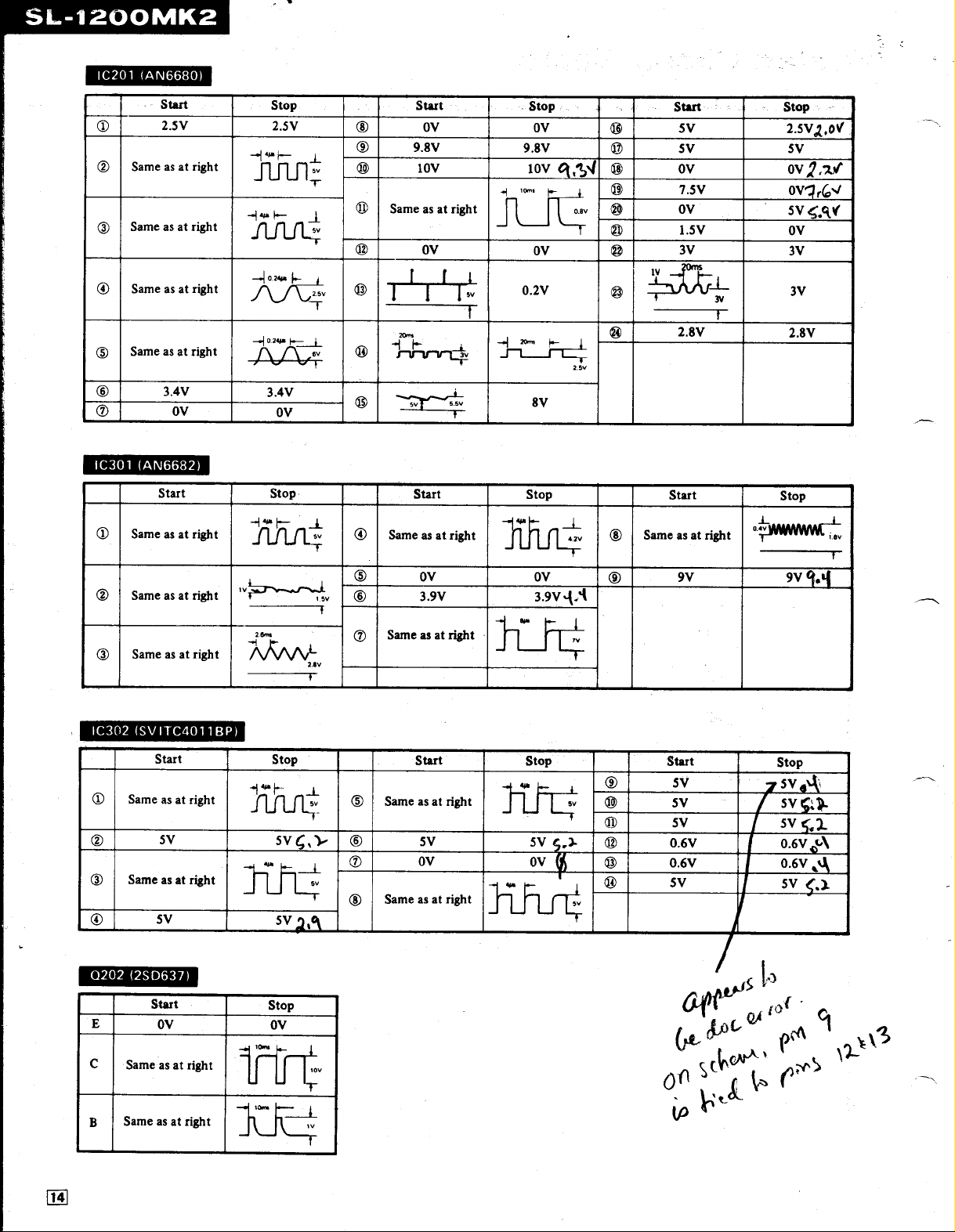
IC201
(AN6680)
Ot
T
T
T5
©
T7
IC301
Tt
T
Start
2
.5V 2
Same
as at
Same
as at
Same
as at
Same
as at
3
.4V
OV
(AN6682)
Start
Same
as at
Same
as at
Same
as at
Stop
.5V
right
right
right
41.
fl
fl
u
u
w
A
6v
v
.xw
x
.sv
7
right
~oxw
-[A-,-!V
3
.4V
i
OV
Stop
right
JULJ
sv
L
T
right'v
right
x
.sv
~-
Start
®
1)
OV
9.8V
tov
Same
as at
right
-
©
®3
Ov Ov
-
20-
,
T
Stop
Ov
9.8V
iov
.2V
0
.
,3J
o
9v
Start
I
LM
Q
5V
5V
Ov
OO
I
t
®
®
®
®
i
~~
IV
7
.5V
OV
1
.5V
3V
2.8V
r
st
o
p
- :
2
.5VZ,OV
5V
OV,?,7. ,V`
Ov
4
Sv
,qY
OV
3V
3V
2
.8V
.4
®
2
.5V
S .SV
©
sv
Start
Same
®
TO
©
as at
right
OV Ov
3.9V
lhf
8v
Stop
3
t
.9V,(A
,.,®
TB
Start
Same
as at
right
9V 9v
Stop
-
-v
-
T
'
w
Same
as at
right
I
I I
1
IC302
T1
Ts
®
0202
E
C
t
B
(SV
ITC4011
Start
Same
as at
right
5V
Same
as at
right
SV
(2SD637)
Start
OV OV
Sameasat
Same
as at
right
right
BP)
T4A
~
Stop
41 ~-
Stop
Start
T5
Same
as at
right
5V
-~
OO
5V
OV
Sv
®
Same
as at
right
,
Stop
y,
5V
OVI~t
Start
Stop
O
,
'~
©
SV
t .
Sv
5V
v
T
Page 15

BLOCK
DIAGRAM
Position
detection
coil
0
U
D201
(33r.p.m.
D202
(45r.p.m.
D201
(33r.p.m.
D202
(45r.p.m.
S203
(Start/Stop
indicator)
indicator)
switch)
switch)
switch)
Page 16

01-2
.3
D1
AC
line
50/60
Hz
Rectifier
IC201
Speed
control
(AN6680)
0
.S .C
0203
0
~
E
~E
0
c
ci
ca
c
CD
cli
IC301
f
C
.R
OSC
1
_
2 3
P
.C
u
vCC
(AN6682)
C
u
9
{
.P
PF
!
16
S
~C
rtUU'a
"tVh
0
U
S301
VR303
1~
S301
~7
PITCH
SWITCH
LOCK
,n
0
M
v
Page 17

SL-1200MK2
SL-12C
EXPLODED
VIEWS
POWER
CIRCUIT
P
.C.B.
Page 18

TONE
ARM
and
ARM
BASE
ASS'Y
Page 19

REPLACEMENT
Notes
:1.Part
Ref.No
CABINET
1
2
-
3
4
6
7
8
9
10
11
12
13
14
15
16
17
18
19
20
21
22
23
24
25__
26
27
28
29
30
31
32
33
34
35
36 SFUP025-01
37
38
39
40
41
42
43
44
45 SFUP122-01
46
47
48
49
50
51
52
53
54
55
IM]
65
[MCI
56
57
58
TONE
61
62
63
64
65
66
67
68
70
71
72
73
74
numbers
Please
and
indicates
CHASSIS
and
use
ARM
2.©
3.SL-1200MK2(M)
.
ARM
this part
that
PartNo.
PARTS
SFAD122-01A
SFTG172-01
SFTE172-01Z
SFUM172-05
SFMGQ20401
SFMG520-31A
SFMZ172
SFMZQ20-01A
SFUP122-12
SFAC122-01
SFUM172-04
SFKT122-01
SFKK122-01E
SFKTO15-06
SFQA122-01
SFUM122-01
SF
KTbtS-01E
SFDJ
SFGZ122-01
SFYB5-32
SFQA520-01
SFUM122-03
SFUM015-11
SF
KK172-01
SFXB122-02
SFQA172-01
SFXJ172-01
SFUP122-02E
SFUP122-03
SFDJ122-03E
SFX0172-01
SFQA520-01
SFQA001-02
SFXJ172-05
SFHKO40L
RJASVA
SFUP132-03
SFGC122-01
SFUP122-10
KT122-02
SF
SFKK122-03
SFUZ122-01
'
F
SFDJ122-01E
SFUP122-13
SFAU122-01
SFUP122-05
SFUP122-04
SFUM170-07
SFGC122-02E
SFUP122-06
SFKTO15-02E
SFNN122M01
SFNN122COI
SFX0122-01
SFX0122-02
SFAT122-01A
BASE
SFPCC31001
SFPAM18201
SFPWG17201K
SFPRT18201K
SFPZB17202
SFQA829-03
SFPAB13202
SFPJL18202K
SFPZB12203
SFUM170-06
SFPZB12204
SFPAB18201
SFPZB12201
PARTS
are
indicatedonmost
number
only
parts
+(MI,SL-120wIK2(MC)
-01E
I22,02E
-
"
1
K
K
K
K
LIST
for
parts
specifiedbymanufacturer
Part
Name&
Dust
Cover
Turntable
Mat
Turntable
Cover, Turntable
Cover,
Stater
Stater
rame
Detector
FG
Shaft,
Stater
Plate,
Shield
Cabinet
Ornament,
Knob,
Case,
Knob,
Spring,
Base,
Knob,
Connector,
Spacer,
Ball,
Spring,
Cam,
Spacer,
Cover,
Boss, Drive
Spring,
Pin,
Bracket,
Plate,
Connector,
Pin,
Spring,
Spring,
Pin,
Clamper;AC
Bracket,
AC
Bracket,
Cushion,
Spacer,
Knob,
Ornament,
Shading
Hqlder,
-
Bucket,
Connector,
Supporter,
Base,
Supporter
Supporter
Case,
Audio
Supporter
Knob, Speed
Name
Stylus-illuminator
Power
Strobe-illuminator
Start/Stop
Start/S1op
Operation
Speed
7-PIN
Rubber
Switch
Switch
Switch
LED
Lamp
Drive Boss 0
Lock
Canceler 0
Stylus-illuminator
.Lock
Operation
3-PIN
Guide
Lock
Lock
Lock
Operating
AC
Cord
Power
Power
Power
Pitch
Pitch
Cloth,
LED
Pitch
4-PIN
Bottom
Bottom
(A),
(B),
Hinge
Insulator
(C),
Plate
Name
Plate
Pipe
(A)
Pipe
(B)
Hinge
Ass'y
Head
Shell
Tone
Arm
Balance
Lift
Knob,
Spring,
Knob,
Oil
Plate,
Spacer,
Clamper,
Tone
Ass'y
Weight
Assy
Arm
Lift
Arm
Damper P4
Arm
Base
Phono
Phono
Arm
Fixing
Plate,
Position
(Mechanical)
mechanical
orders
Frame
Coil
Frame
Switch
Selector
(Speed
Cam
Cam
Canceler
Operating
Cord
Cord
Transformer
Transformer
Transformer
Control
Pitch
Control
Hinge
Hinge
Hinge
Selector
Base
Ass'y
Lift
Cord
Fix
parts
+[MC1
Selector)
Pin
Plate
M'tg
Volume
Volume
Ass'y
.
M'tg
Volume
.m)
.
Description
-
Ass'y
Ass'y
Ass'y
Switch 0
Knob
(33-1/3r.p.m
Plate
Volume
Control
Control
Base
(45r.p
Ass'y
Lock
Cover
Cord
Plate
for
be
used
.)
-
-
safety
Ref.No
75
[M]
75
(MC)
76
77
78
79
80
81
SCREWS,
0
0
0
0
0
0
0
0
0
0
0
0
0
0
0
0
0
0
0
0
0
0
0
0
0
0
0
0
0
0
0
0
0
0
0
0
0
0
ACCESSORIES
A1
[MI
A1
[MCI
A2
A3
A4
A5
A6
A7
A8
PACKINGS
[M]
P1
P1
[MCI
P2
P3
P5
P6
P7
P8
.
.
WASHERS
-
PartNo.
SFDH360MOl
SFDH028-01
-
SFP1720
SFPKDKD1720
SFPKB17201S
SF P
12201
SFPAB
17206
and
CIRCLIPS
XTN3+88FZ
-FXGQ20-02
XTN3+88
XTN26+88
XTN4+10B
XWA48
XUC3FT
XUC2FT
XUC25FT
SFXW910J02
XTN3+408FZ
XSN3+10BVS
XWE3F12FZ
XTN3+25BFZ
SFXW122-01
XWE3E10
SFPEW1100
SFPEW11003
XSN3+BS
SFXG132-01
XTV3+BBFN
XTN3+108
XTN2+108
XSN17+3FY
XSN3+149
SFXW172-04
XUB14FT
SFUZ172-05
XTN3+6B
XSN3+8S
XWA3BFZ
XWA38
XWG3
SFXG829-1
XUCSFT
XTW3+SB
XTV3+88FN
XWE4A10EW
XTN3+258
XYN3+C6FZS
XSN3+128VS
SFPEW17201
XWG26
SFNU122MOl
SFNU122C01'
SFWE010
SFPEN3302
SFPEW9601
SFCZV8801
SFPEV9801
SFK0135-01
SFPZB3501
SFHP122MOl
SFHP122COl
SFHH122-01
SFHH122-02
SFHD122-01
SFHD122-02
SFHD122-03
SFYH60X60
SFYH40X45
Part
Name&Description
Phono
Cord
Phono
Cord
GroundWire
ArmRest
Arm
Base
Ring,
ng,
Arm
Base Operation
Arm
Anti-skate
45
Cartridge
Cartridge
Cartridge
Cartridge
Gauge
Weight
Front
Rear
Top
(A),
Turntable
(B),
Turntable
Book
Book
r.p.m
Base
Force
Control
.
Turntable Unit
Bracket,
Knob,
Screw
Screw
Screw
Screw
Screw
Washer
Circlip
Circlip
Circlip
Washer
Screw
Screw
Washer
Screw
Washer
Washer
Washer
Washer
Screw
Screw
Screw
Screw
Screw
Screw
Screw
Washer
Circlip
O
Ring
Screw
Screw
Washer
Washer
Washer
Screw
Circlip
Screw
Screw
Washer
Screw
Screw
Screw
Washer
Washer
Instruction
Instruction
Adaptor,
Nut,
Washer,
Screw,
Screw,
Overhang
Shell
Carton
Carton
Pad,
Pad,
Pad,
Pad,
Pad,
Polyethylene Cover,
Dust Cover
Polyehtylene Cover, Turntable
and
Page 20

EXPLODED
VIEWS
20
PrintedinJapan
 Loading...