

Page 1
ORDERNO.AD9903091C1
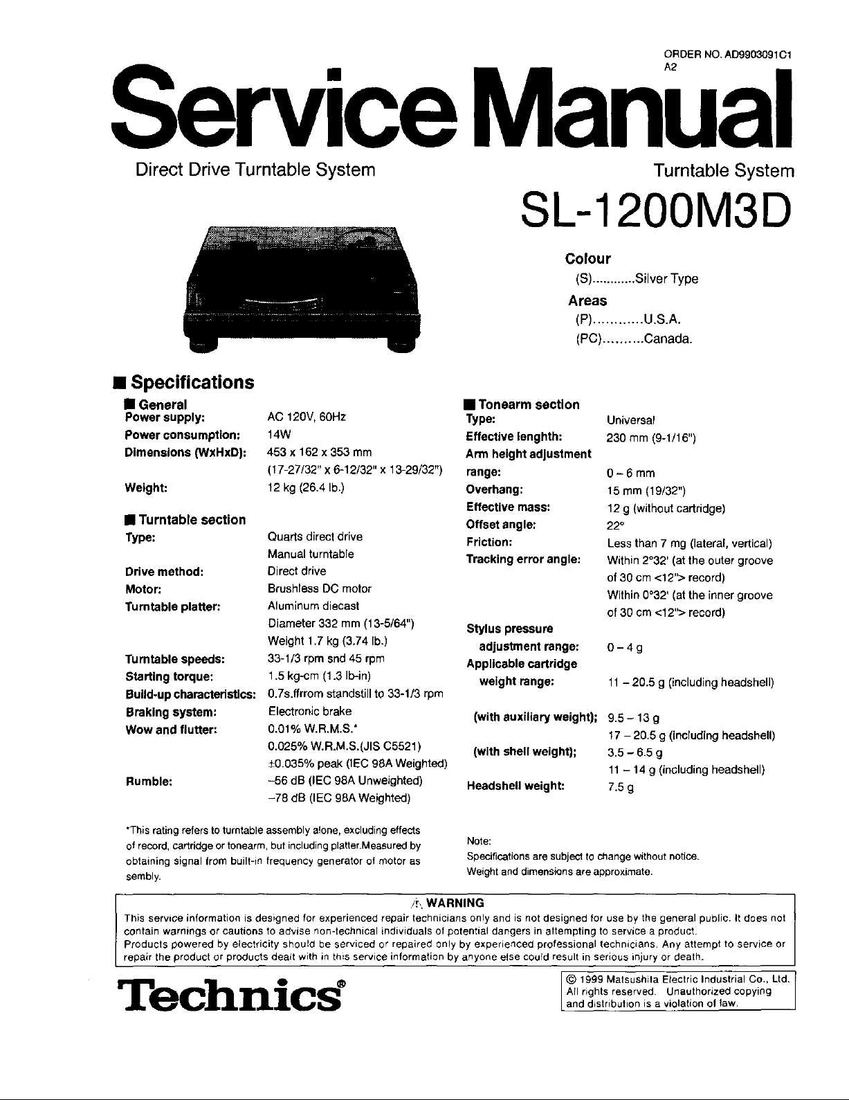
Service Manual
Direct Drive Turntable System Turntable System
SL-1200M3D
Colour
(S)............Silver Type
Areas
(P)............ U.S.A.
(PC).......... Canada.
• Specifications
• General
Power supply:
Power consumption:
Dimensions (WxHxD):
Weight:
• Turntable section
Type:
Drive method:
Motor:
Turntable platter:
Turntable speeds:
Starting torque:
Build-upcharacteristics:
Braking system:
Wow and flutter:
Rumble:
AC 120V,60Hz
14W
453 x 162 x 353 mm
(17-27/32" x 6-12/32" x 13-29/32")
12 kg (26.4 lb.)
Quads direct drive
Manual turntable
Direct drive
Brushlees DC motor
Aluminum diecast
Diameter 332 mm (13-5/64")
Weight 1.7 kg (3.74 lb.)
33-1/3 rpm snd 45 rpm
1.5 kg-cm (1.3 Ib-in)
0.7s.ffrrom standstill to 33-1/3 rpm
Electronic brake
0.01% W.R.M.S."
0.025% W.R.M.S.(JIS C5521 )
±0.035% peak (IEC 98A Weighted)
-56 dB (IEC 98A Unweighted)
-78 dB (IEC 98A Weighted)
• Tonearm section
Type:
Effective lenghth:
Arm height adjustment
range:
Overhang:
Effective mass:
Offset angle:
Friction:
Tracking error angle:
Stylus pressure
adjustment range:
Applicable cartridge
weight range:
(with auxiliary weight);
(with shell weight);
Headshell weight:
Universal
230 mm (9-1/16")
0-6mm
15 mm (19/32")
12 g (without cartridge)
22°
Less than 7 mg (lateral, vertical)
Within 2032' (at the outer groove
of 30 cm <12"> record)
Within 0032' (at the inner groove
of 30 cm <:12">record)
0-4g
11- 20.5 g (including headshell)
9.5- 13g
17 -20.5 g (including headshell)
3.5 - 6.5 g
11- 14g (inaluding headshell)
7.5 g
*This rating refers to turntable assembly atone, excluding effects
of record, cartridge or tonearm, but including platterMeasured by
obtaining signal from built-in frequency generator of motor as
sembly.
/i,. WARNING
This serviGe information is designed for experienced _epair technicians only and is not designed for use by the general public. _tdoes not
contain warnings or cautions to advise non-technical individuals of potential dangers in attempting to service a product.
Products powered by electricity should be serviced or repaired only by experienced professional technicians. Any attempt to serwce or
repair the product or products dealt with in this service information by anyone else cou(d result in serious injury or death.
Technics °
Note:
Specifications are subject to change without notice.
Weight and dimensions are approximate.
© 1999 Matsushita Electric Industrial Co., Ltd.
All rights reserved Unauthorized copying
and distribution is a violation of law,
Page 2
SL-1200M3D J
• Contents Page
• Safety Precaution ..................................................... 2
• Accassorles ............................................................... 2
• Features ..................................................................... 3
• Controls ..................................................................... 3
• Preparation of the cartridge ..................................... 3
• Putting the player together ...................................... 4
• Connections and installation ................................... 5
• Preparatory adjustments ...................................... 6,7
• Playing records ......................................................... 8
• Adjustments while using the unit ............................ 9
• Maintenance ............................................................ 10
• Troubleshooting guide ........................................... 11
•Operation Checks and
Component Replacement Precedures ... 12-16
•Schematic Diagram .......................................... 17-19
•Printed Circuit Boards ...................................... 20-22
• Measurements and Adjustments ........................... 23
•Block Diagram ......................................................... 24
•Wiring Connection Diagram ................................... 25
• Repracement Parts List ..................................... 26,27
•Cabinet Parts Location ...................................... 28,29
• Packaging ................................................................ 30
Page
• Product service ....................................................... 10
• Safety Precaution (This "Safety Precaution" is applied only inU.S.A.)
1.Before servicing,unplug the power cordto prevent anelectric shock.
2. When replacing pads, use only maanufaacturer's recomended components for safety.
3. Check the COnditionof the power cord. Replace if wear or damage isevident.
4. After servicing, be sure to restore the lead dress,insulationbarriers, insulation papers, shields,etc.
5. Before returningthe serviced equipment to the customer,be sure to make the following insulation resistancetest to prevent the customer from
being exposed to a shock hazard.
• INSULATION RESISTANCE TEST
1. Unplugthe power cord and short the two prongs of the plug with a jumper wire.
2. Turn on the power switch.
3. Measure the resistance value withohmmeter between the jumpered AC plug and each exposed metal cabinet pad, such as screwheads antenna,
controlshafts, handle brakets, etc. Equipmentwithantenna terminals shouldread between 3 MQ and 5.2 MQ to all exposed pads. (Fig. A)
Equipment withoutantenna terminals should read approximately infinityto all exposed pads. (Fig. B)
Note: Some exposed pads may be isolated from the chassis by design. These will read infinity.
Antenna J
terminal _
Ohmmeter
(Fig. A)
Resistance = 3 MQ - 5.2 M_
4. If the measurement is outside the specified limits, there is a possibilityofa shock hazard. The equipment should be repaired and rechecked before
it isreturned to the customer.
(Fig. B)
Resistance= Approx. o_
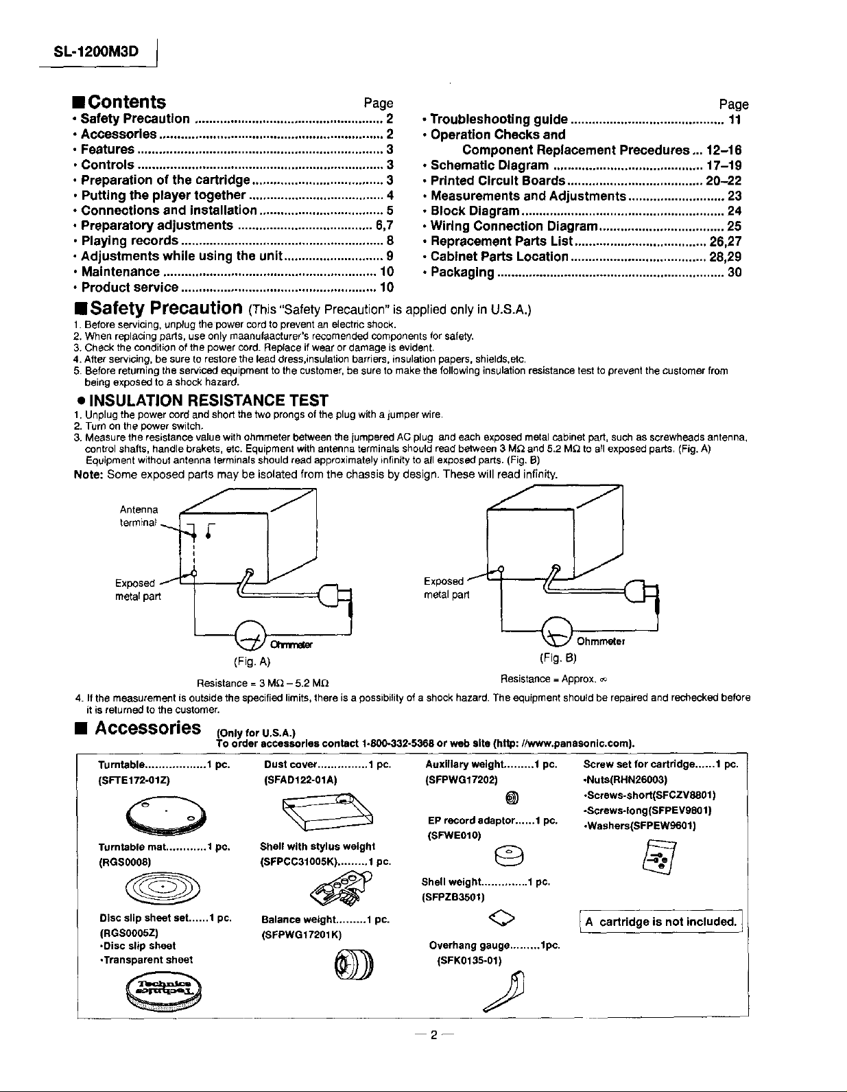
Accessories (onlyforU.S.A.)
TOorder accessories contact 1.800-332-5368 or web site (http://www.panasonlc.com).
Turntable .................. 1 pc.
(SFTE172-OIZ)
0
Turntable mat ............ t pc,
(RGS0OOS)
Disc slip sheet set......1 pc.
(RGS0005Z)
•Disc slip sheet
•Transparent sheet
Dust cover ............... 1 pc.
(SFADI22-OIA)
Shell with stylus weight
(SFPCC31005K) ......... 1 pc.
Balance weight ......... 1 pc.
(SFPWG17201 K)
@
Auxiliary weight ......... t pc.
(SFPWG17202)
@
EP record adaptor......1 pc.
(SFWE0t0)
Shell weight .............. 1 pc.
(SFPZB3501)
<>
Overhang gauge ......... 1pc.
(SFK0135-01)
Screw set for cartridge..,...1 pc.
.Nuts(RHN26003)
•Screws-short(SFCZV8801 )
•Screws-long(SFPEVg801 )
-Washers(SFPEW9601)
I A cartridge is not included. 1
2--
Page 3
(Shell
weight'l)
Stylus
@
@
--@
/-@
--@
(Stylusweight"2)
cartridge
stylus weight
gauge
I SL-1200M3D
• Featu res
A masterpiece amongst turntables with a worldwide reputa-
tion.
Pitch control reset button
• Pitchcan beinstantlyresettothe rated speed(33 1/3 or 45 rpm).
Highly accurate turntable speed maintained continuously
with a quartz pitch control
• The pitchcanbe variedbetween-8 and+8%, withaccuracymain-
tainedthroughouttherange.
The direct drive produces high torque
• Wowand flutterbelow0.01%. Starting torqueof 1.5 kg/cmenabting
theturntableto reach33 1/3rpm in 0.7seconds.
• Fullyelectricbrakingsystem.
Tone arm with gimbal suspension
• Thetonearmcanbefinelyadjustedina rangeof 6 millimeterswiththe
Iockableheightcontrol
Anti-vibration design with 3 layer cabinet construction and
large insulating legs.
Pop-up stylus light.
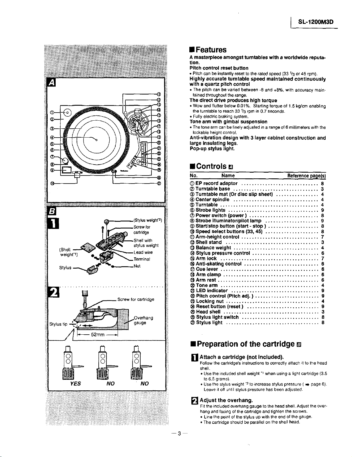
• Controls []
No. Name Referenceparle(s)
(DEP record adaptor ............................. 8
_) Turntable base ................................ 3
_) Turntable mat (Or disc slip sheet) ................ 4
_) Center spindle ................................ 4
_) Turntable ..................................... 4
® Strobe lights .................................. 9
(_ Power switch (power) .......................... 8
_) Strobe illuminator/pilot lamp .................... 9
® Start/stop button (start - stop ) ................... 8
Speed select buttons (33, 45) .................... 8
Arm-height control ............................. 7
Shell stand ................................... 3
O Balance weight ................................ 4
@ Stylus pressure control ......................... 6
Arm lock ..................................... 7
Anti-skating control ............................ 6
_) Cue lever ..................................... 6
Arm clamp .................................... 6
(_ Arm rest ...................................... 6
Tone arm ..................................... 4
LED indicator ................................. 9
Pitch control (Pitch adj. ) ........................ 9
Locking nut ................................... 4
Reset button (reset) ........................... 9
Head shell .................................... 3
Stylus light switch ............................. 8
@ Stylus light ................................... 8
YES NO NO
• Preparation of the cartridge D
[] Attach a cartridge (not included).
Follow the cartridge's instructions to correctly attach Stto the head
shell,
• Use the included shell weight "_ when using a light cartridge (3.5
to6.5 grams).
• Usethestylusweight-2toincreasestyluspressure( ,,_page 6).
Leaveit oftuntilstylus pressurehasbeenadjusted.
[] Adjust the overhang.
Fit the included overhang gauge to the head shell.Adjust the over-
hang and facing of the cartridge and tighten the screws.
• Line the point of the stylus up with the end of the gauge,
• The cartridge should be parallel on the shell head.
--3--
Page 4
SL-1200M3D J
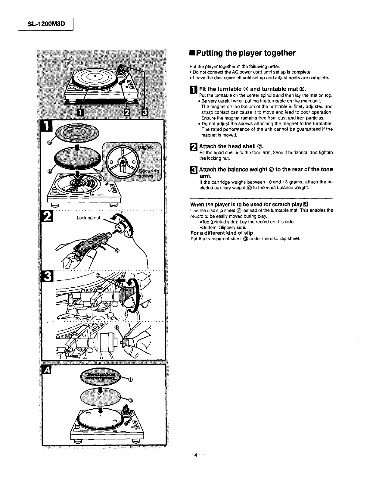
• Putting the player together
Put the player together in the following order.
• Do not connect the AC power cord until set up is complete.
• Leave the dust cover off until set up and adjustments are complete.
ill Fit the turntable ® and turntable mat @.
Putthe turntable on the center spindleand then Jaythe mat on top.
• Be very careful when putting the turntable on the main unit.
The magnet on the bottom of the turntable is finely adjusted and
sharp contact can cause it to move and lead to poor operation.
Ensure the magnet remains free from dust and iron particles.
• Do not adjust the screws attaching the magnet to the turntable.
The rated performance of the unit cannot be guaranteed if the
magnet is moved.
[] Attach the head shell @.
Fittheheadshellintothetonearm,keep it horizontalandtighten
thelockingnut.
[_"] Attach the balance weight @ to the rear of the tone
arm.
If thecartridge weighsbetween 10and 13 grams, attachthe in-
cludedauxiliaryweight_) tothemainbalanceweight.
ill ...... ii i_uH
When the player Is to be used for scratch play IE]
Use the disc slipsheet _) instead of the turntable mat. This enables the
record to be easily moved during play,
•Top (printedside): Lay the record on this side.
•Bottom: Slippery side,
For a different kind of slip
Putthe transparent sheet @ under the disc slip sheet,
--4--
Page 5
I SL-1200M3D
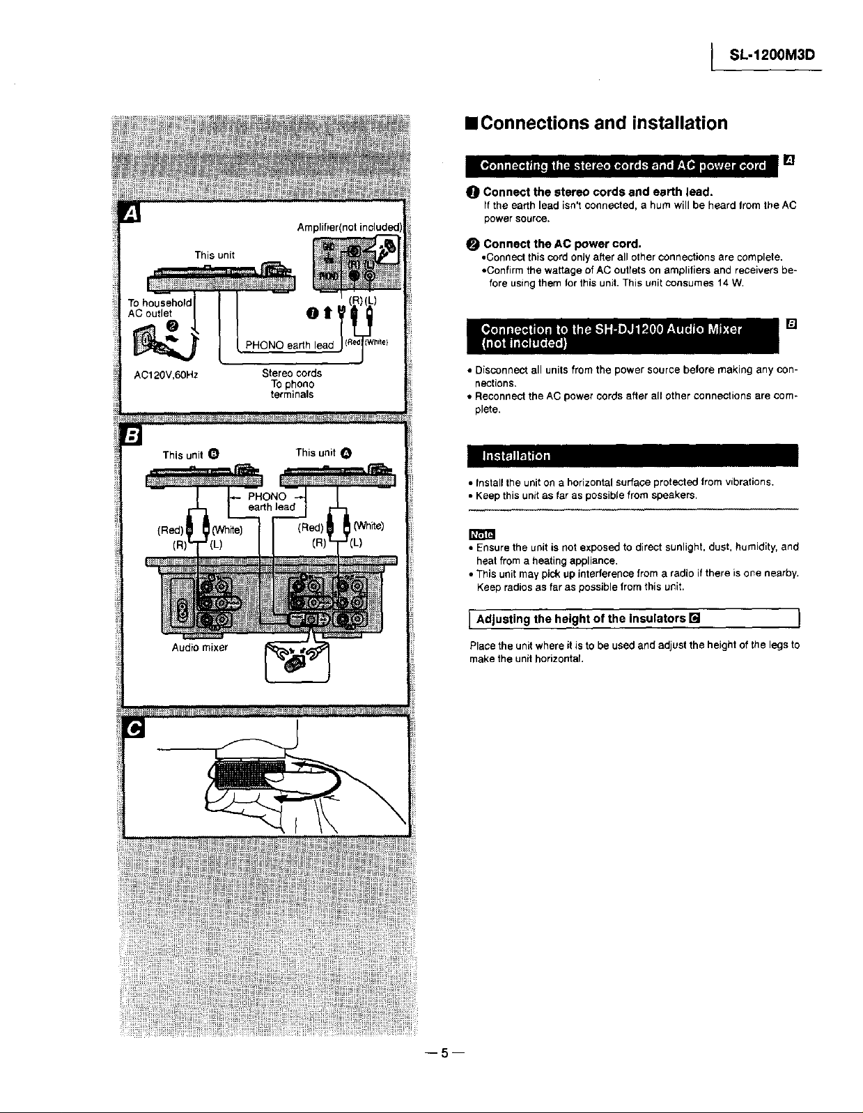
• Connections and installation
0 Connect the stereo cords and earth lead.
If the earth lead isn't connected, a hum will be heard from the AC
power source.
This unit
To household
AC outlet O l
AC120V,60Hz Stereo cords
This unit O This unit O
, N
_" _ (Whffe)_ r _(Red) 6 _ (White)
To phono
terminals
earth lead
'"")(°)-25!...........11 ,.,-°,L,
9
? _N Nk
Audio mixer I
Connect the AC power cord.
• Connect this cord onlyafter all other connections are complete.
• Confirm the wattage of AC outlets on amplifiers and receivers be-
fore using them for this unit. This unit consumes 14 W.
[]
• Disconnect all units from the power source before making any con-
nections.
• Reconnect the AC power cords after all other connections are com-
plete.
[_
• Install the unit on a horizontal surtaoe protected from vibrations.
• Keep this unit as far as possible from speakers.
• Ensure the unit is not exposed to direct sunlight, dust, humidity, and
heat from a heatingappliance.
• This unit may pick up interference from a radio if there is one nearby.
Keep radios as far as possible from this unit.
] Adjusting the height of the insulators [] I
Place the unit where it is to be used and adjust the height of the legs to
make the unit horizontal,
Page 6
SL-1200M3D I
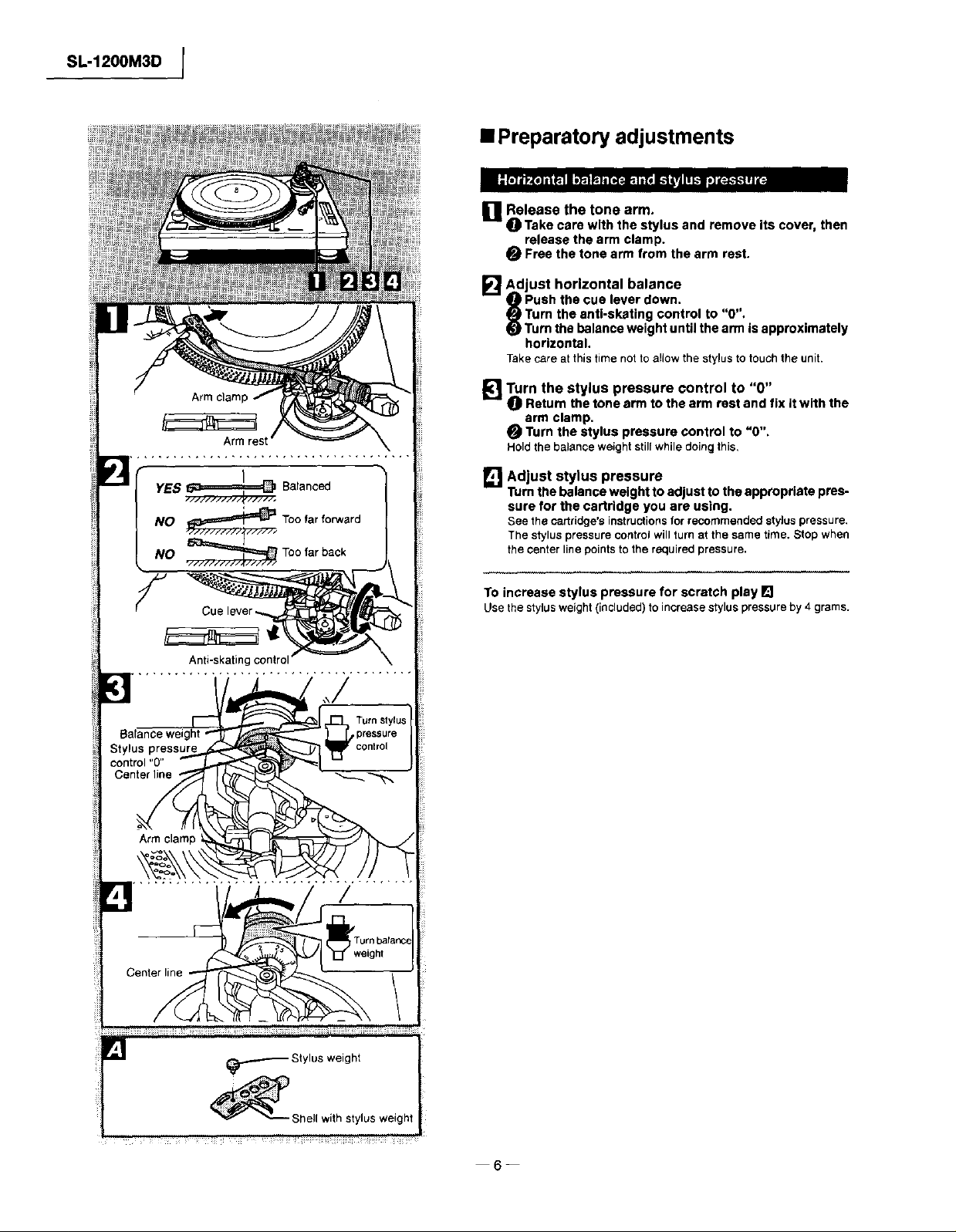
• Preparatory adjustments
i'_Release the tone arm.
O Take care with the stylus and removeits cover, then
release the arm clamp.
O Free the tone arm fromthe armrest.
_'_1Adjust horizontal balance
9 Push the cue lever down.
_P_Turn the anti-skating control to "0",
(fJ)Turn the balance weight until the arm is approximately
horizontal.
Takecareatthistime notto allowthe stylus totouch theunit.
Armclam
Armrest
, . ,
YES 6_======_ Balanced
,,/#///'/,,'///_/#/#/,
NO _ Too far forward
NO _ Toofarback
./#////-////,r/..-//-#/
F
Anti-skatingco
[]Turn the stylus pressure control to "0"
Return the tone arm to the arm rest and fix it with the
arm clamp.
Turn the stylus pressure control to "0",
Holdthebalanceweightstillwhiledoingthis,
[] Adjust stylus pressure
Turnthebalanceweightto adjustto theappropriatepres-
sure for the cartridge you are using.
See the cartridge's instructionsfor recommended stylus pressure.
The stylus pressure contrctwill turn at the same time. Stop when
the center linepoints to the required pressure.
To increase stylus pressure for scratch play []
Usethestylusweight(included)toincreasestyluspressureby4 grams.
Armclamp
/
Page 7
[_ ;._Released_ i_d i
I SL-1200M3D
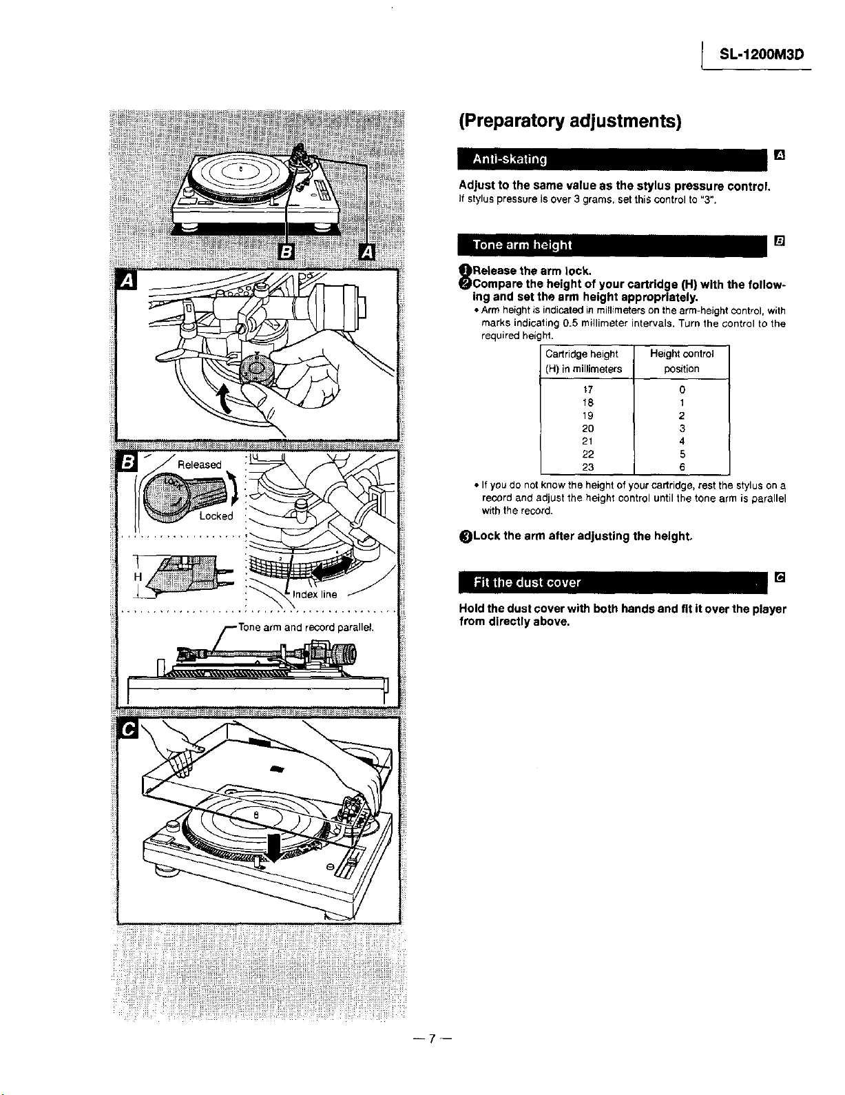
(Preparatory adjustments)
, o J I_
Adjust to the same value as the stylus pressure control.
Ifstyluspressureisover3 grams,setthiscontrolto"3".
• - o - • _']
Release the arm lock.
Compare the height of your cartridge (H) with the follow-
ing and set the arm height appropriately.
• Arm heightis indicatedin millimeters on the arm-height control,with
marks indicating 0.5 millimeter intervals, Turn the control to the
required height.
Cartridge height
(H) in millimeters
t7
18
19
2O
21
22
23
• If you do not know the height of your cartridge, rest the stylus on a
record and adjust the height control until the tone arm is parallel
with the record.
Height control
position
0
1
2
3
4
5
6
_Lock the arm after adjusting the height.
• • • o []
Hold the dust cover with both hands and fit itover the player
from directly above,
--7 1
Page 8
SL-1200M3D J
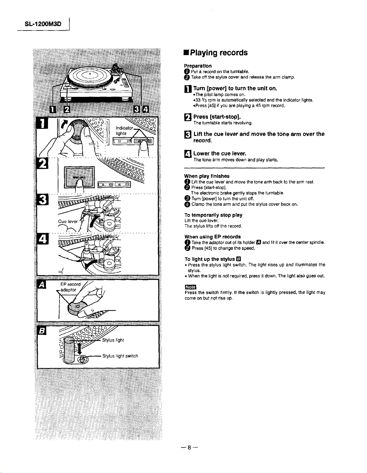
==Playing records
Preparation
Put a record on the turntable.
Take off the stylus cover and release the arm clamp.
[] Turn [power] to turn the unit on.
•The pilot _ampcomes on.
• 33 1/3rpm is automatically selected and the indicator lights.
• Press 145]if you are playing a 45 rpm record.
[] Press [start-stop].
Theturntablestartsrevolving,
_] Lift the cue lever and move the tone arm over the
record.
LK1Lower the cue lever.
Thetonearmmovesdownandplaystarts.
When play finishes
! Liftthe cue lever end move the tone arm back tothe arm rest.
I Press [start-stop].
The electronic brake gently stops the turntable,
Turn [power]to turn the unitoff.
C_ampthe tone arm and put the styluscover back on.
] EP record
adaptor
To temporarily stop play
Lift the cue lever,
The stylus liftsoff the record.
When using EP records
Takethe adaptor out of itsholder[] and fit itover the center spindle.
Press [45] to change the speed.
To light up the stylus []
• Press the stylus light switch, The light rises up and illuminates the
stylus,
• When the light is not required, press it down, The light also goes out.
Press the switch firmly. If the switch is lightly pressed, the light may
come on but not rise up.
o _oo
_ght
os,ohtswtch
--8--
Page 9
[] I ........
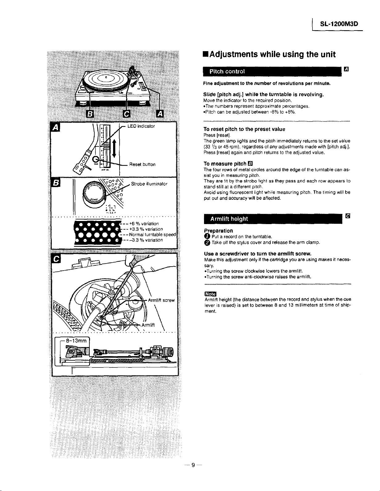
_-- LED indicator
-- Reset button
oo o o\ Strobe illuminator
oO° o
SL-1200M3D
==Adjustments while using the unit
Fine adjustment to the number of revolutions per minute.
Slide [pitch adj.] while the turntable is revolving.
Move the indicator tothe required position.
•The numbers represent approx+mate percentages.
•Pitch can be adjusted between -8% to +8%
To reset pitch to the preset value
Press [reset].
The green lamp _ights and the pitch immediately returns to the set value
(33 1/3or 45 rpm), regardless of any adjustments made with [pitchadj.].
Press [reset] again and pitch returns tothe adjusted value.
To measure pitch
The four rows ofmetal circles around the edge of the turntable can as-
sist you in measuring pitch.
They are fit by the strobo llght as they pass and each row appears to
stand still at a differentpitch.
Avoid usingfluorescent tight while measuring pitch. The timing will be
put out and accuracy wi!l be affected.
-- +3.3 % variation
,__-- - +6 % variation
--- Normal turntablespeed
---3.3 % variation
• . • []
Preparation
_]_ Put a record on the turntable.
O Take off the stylus cover and release the arm clamp.
Use a screwdriver to turn the armlift screw.
Make this adjustmentonly if the cartridge you are using makes itneces-
sary.
• Turning the screw clockwise lowers the armlift.
• Turning the screw anti-ctockwise raises the armliff.
Armlift height (the distance between the record and styluswhen the cue
lever is raised) is set to between 8 and 13 millimeters at time of ship-
ment.
--9
Page 10
SL-1200M3D I
• Maintenance
I Care of the parts I
To clean this unit, wipe with a soft, dry cloth.
If the surfaces are extremely dirty, usea soft clothdipped ina soap-and-
water solution ora weak detergent solution.
• Never use alcohol, paint thinner,or benzine to clean this unit.
• Before using chemically impregnated cloth, read the instructions that
came withthe cloth carefully.
Do not wipe the dust cover while playing a record.
This can cause static electricity. This staticcan cause the tone arm to be
attracted towards the cover.
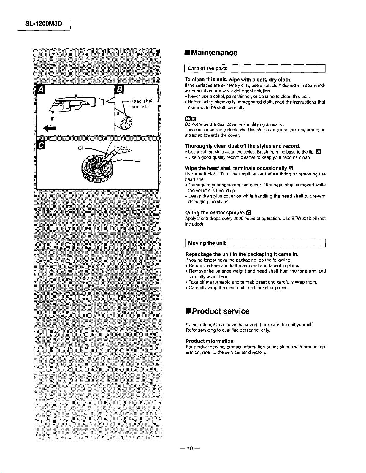
Thoroughly clean dust off the stylus and record.
• Use a softbrush to clean the stylus.Brushfrom the base to the tip. []
• Use a good quality record cleaner to keep your records clean.
Wipe the head shell terminals occasionally []
Use a soft cloth. Turn the amplifier off before fitting or removing the
head shell.
• Damage to your speakers can occur if the head shell is moved while
the volume is turned up.
• Leave the stylus cover on while handling the head shell to prevent
damaging the stylus.
Oiling the center spindle. []
Apply2 or 3 dropsevery 2000 hoursof operation. Use SFW0O10 oil (not
included).
Moving the unit ]
Repackage the unit in the packaging it came in.
If you no longer have the packaging, do the following:
• Return the tone arm to the arm rest and tape itin place.
• Remove the balance weight and head shell from the tone arm and
carefully wrap them,
• Take off the turntable and turntable mat and carefullywrap them.
• Carefully wrap the main unit in a blanket or paper.
• Product service
Do not attempt to remove the cover(s) or repair the unit yourself.
Refer servicing to quaIified personnel only.
Product information
For productservice, product informationor assistance with product oP-
eration, refer to the servicenter directory,
10--
Page 11
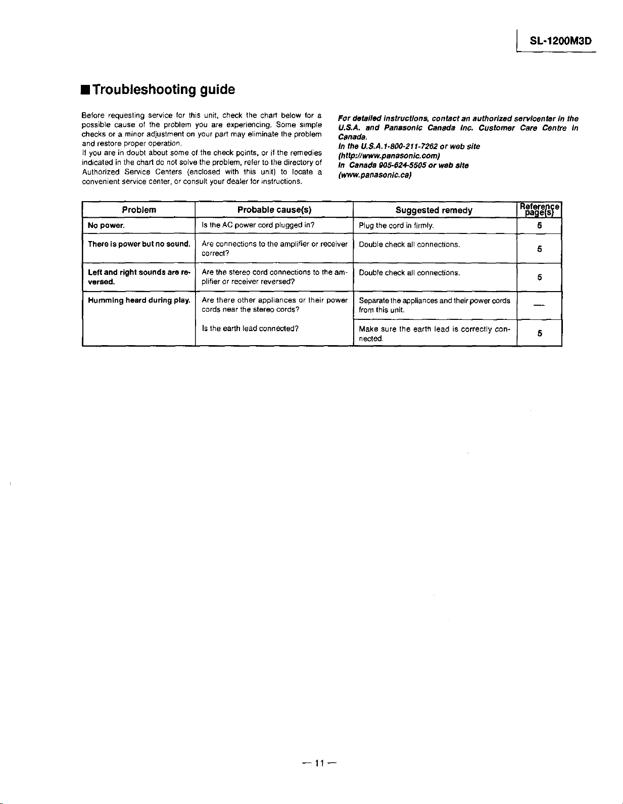
==Troubleshooting guide
l SL-1200M3D
Before requesting service for this unit, check the chart below for a
possible cause of the problem you are experiencing. Some simple
cheeks or a minor adjustment on your part may eliminate the problem
and restore proper operation.
If you are in doubt about some of the check points, or if the remedies
indicated in the chart do not solve the problem, refer to the directory of
Authorized Service Centers (enclosed with this unit) to locate a
convenient service center, or consult your dealer for instructions.
Problem Probable cause(s) Suggested remedy
No power.
There is power but no sound.
Left and right sounds are re-
versed.
Humming heard during play.
Is the AC power cord plugged in?
Are connections to the amplifier or receiver
correct?
Are the stereo cord connections to the am-
plifier or receiver reversed?
Are there other appliances or their power
cords near the stereo cords?
Isthe earth lead connected?
For detailed instructions, contact an authorized servlcenter in the
U.S.A. and Panasoni_ Canada Inc. Customer Care Centre in
Canada.
In the U.S.A. 1.800-211-7262 or web site
(http://www.panasonic, com)
In Canada 905-624-5505 or web site
(www.panasonic, ca)
Reference
page_st
Plug the cord in firmly.
Double check all connections.
Double check all connections.
Separate the appliances andtheir p_wer cords
from this unit.
Make sure the earth lead is correctly con-
nected.
5
5
5
5
11
Page 12

SL-1200M3D I
• Operation Checks and Component Replacement Procedures
m l. This section describes procedures for checking the operation of the major printed circuit
boards and replacing the main components.
2. For reassembly after operation checks or replacement, reverse the respective procedures,
Special reassembly procedures are described only when required.
3. Select item from the following index when checks or replacement are required.
• Contents
• Checking Procedures for each P.C.B. Page.
l. Checking for the drivecontrolF_C,B.and power supplyP.C.B_ . .................... 12.
• Main Component Replacement Procedures
1. Replacementfor the drive coil ass'y and FG coilass'y. ......................... 13,
2. Replacementfor the tonearm unit. • ............................... 13-16.
3. Replacementfor the lamp and stylusilluminatorswitch. • ....................... 16.
4. Replacementfor the parts mountedonspeed selector P,C.B. and powerswitch.• ............. 16.
• Checking Procedures for each P.C.B,
1. Checking for the drive control P.C.B. and
Power supply P.C.B.
Remove the turntable mat and turntable ass'y.
t1"
Tonearm ass'y
Remove the panel
• Check the drive control P,C.B. and power
supply P.C.B, as shown below.
Powersupply P.C.B.
Drive control P.C.B
1. The tonearm ass'y should be supported by arm rest.
2, Take care not to stick the dust or iron powder to the
magnet attached to back inner side of turn table.
--12
Page 13

• Main Component Replacement
Procedures
1. Replacement for the drive coil ass'y and
FG coil ass'y
• Follow the _ - _ of the item 1 in checking
procedure for each P.C.B. on page 12.
_i',= i Remove the
/_!),_ ! spacer.
Claws
_ ._Release the _ claws,
_N-_)_/ ana-th;n remove the
I
drive coil cover.
Drive coilass'y
[SFMG520-31A]
FG coil ass'y
[SFMZ172-01 El
I SL-1200M3D
Connector
(CN103)
Conne_or
(CN101)
m
Remove the 3 connectors.
Removal of the connector
• Release the claws,and then
pulloutthe connector.
Remove the drive
controlP.C.B..
Connector
(CN102)
2. Replacement for the tonearm unit
• Follow the _D of the item 1 in checking procedure
for each P,C.B. on page 12,
Upset the unit, and then put the dust cover.
Turn the insulatorsin the directionof arrow,and then
removethem (4 points).
Insulator
Q
Insulator
¢Dx6
Insulator _'
Unsolder the terminals of
FG coil ass'y (4 points).
Unsolder the terminals of
drive coil ass'y (18 points).
13 +
Unit
Dust cover
I_[ol] =
Use the soft cloth under the unit to prevent
damage the dust cover when servicing.
Page 14

SL-1200M3D I
Remove the bottom
cover (A) ass'y.
Tonearrn ass'y Cabinet ass'y
a
°i°
Dust cover Separatethe dust cover and
the cabinetass'y,and then
removethetonearm ass'y.
Remove the bottom
cover (B) ass'y,
Remove the arm
basecoverplate.
Claws Phonocordclamper
Hold the tonearm with hand when
removing the 3 screws (0),
P ono cord spacer
Remove the lug terminal,
Release the 2 claws, and thenremove the phono
cord clamperand phonocordspacer.
14 w
Page 15
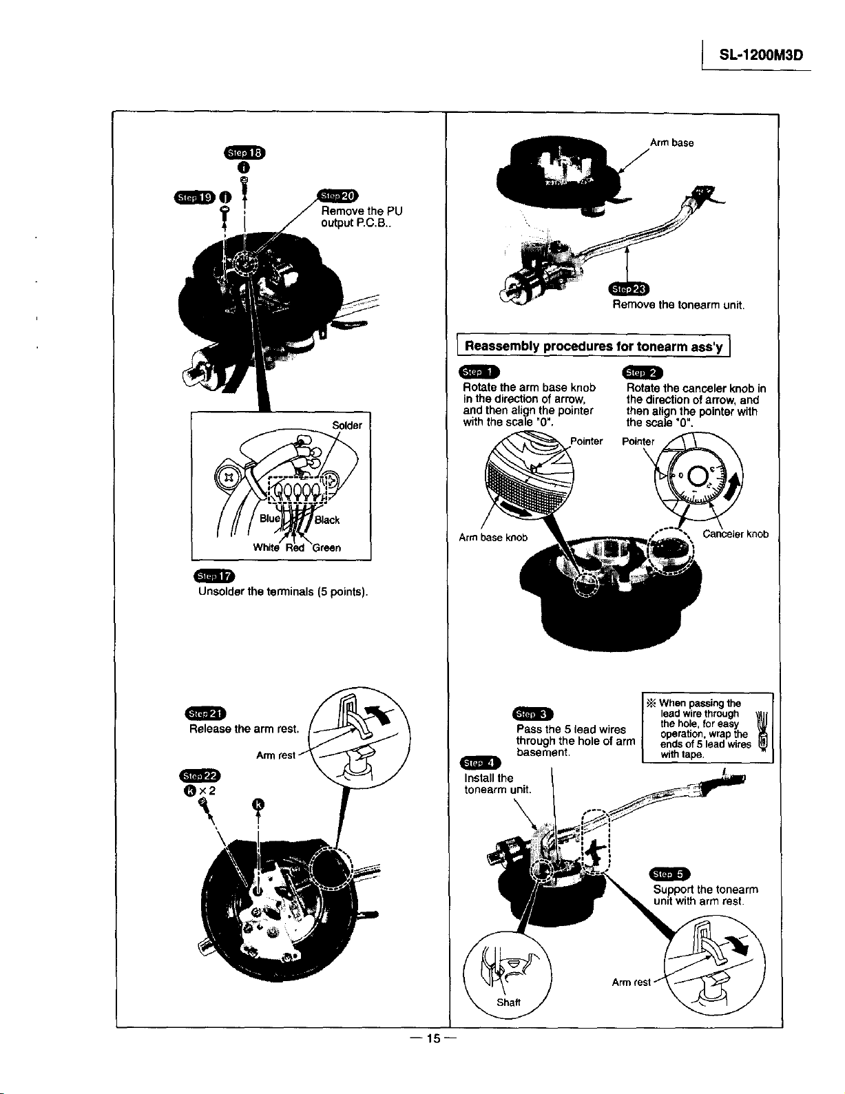
O
Remove the PU
outputP.C,B,.
Solder
Arm base
Remove the tonearm unit.
Reassembly procedures for tonearm ass'y I
/
Rotate the arm base knob
in the directionof arrow,
and then align the pointer
withthe scale "0",
Pointer Pointer
Rotatethe canceler knob in
the directionof arrow,and
thenatignthe pointerwith
the scale _0".
SL-1200M3D
White Red Green
Unsoldarthe terminals (5 points).
I
Release the arm rest.
Arm base knob
Pass the 5 lead wires I oneration wran the
through the hole of arm e_ds of 5'lead_virss
basement, with tape.
Install the
tonearm unit.
\
When passingthe ,,,,,
, the hole, for easy
lead wirethrough
Supportthe tonearm
unit witharm rest.
I16h
Page 16
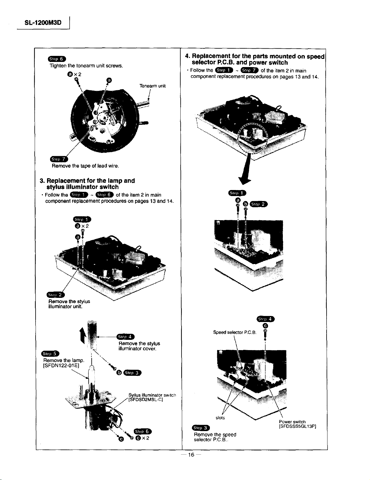
SL-1200M3D [
!
"13ghten the tonearm unit screws.
Ox2
P Tonearmunit
Remove the tape of lead wire.
3. Replacement for the lamp and
stylus illuminator switch
• Follow the _ ~ _ of the item 2 in main
component replacement procedures on pages 13 end 14.
mll
Ox2
4. Replacement for the parts mounted on speed
selector P.C.B. and power switch
• Follow the _D ~ _ Of the item 2 in main
component replacement procedures on pages 13 and 14.
!
Remove the stylus
illuminatorunit.
t
_',._ illuminator cover.
n
Remove the lamp.
[SFDN122-01E] "%h,..
"e
Remove the stylus
Syilus illuminator switch
Speed selector P,C.B.
slots
Remove the speed
selector P.CB,
16
m
Power switch
[SFOSSSSGL13P}
Page 17
I SL-1200M3D
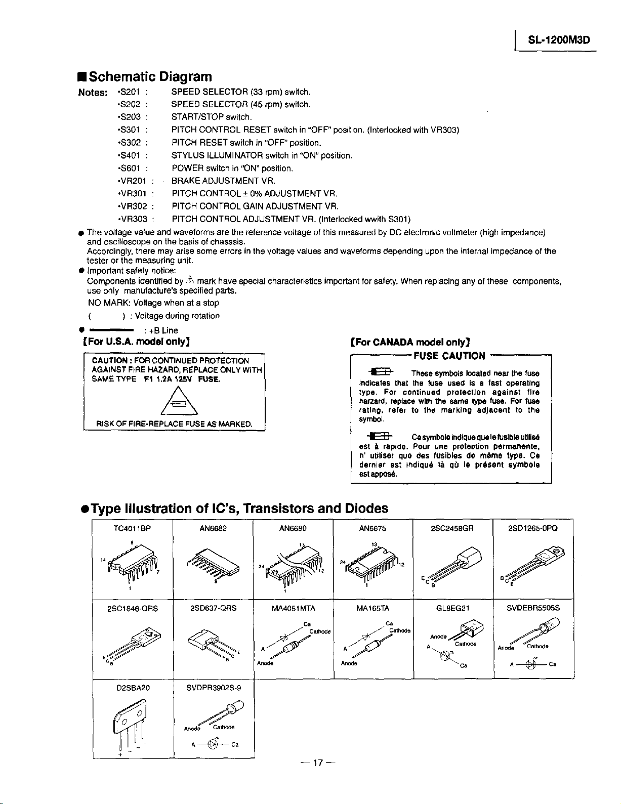
• Schematic Diagram
Notes: ,S201
• The voffage value and waveforms are the reference voltage of this measured by DC electronic voltmeter (high impedance)
and oscilloscope onthe basis of chasssis.
Accordingly, there may arise some errors in the voltage values and waveforms depending upon the internal impedance of the
tester or the measuring unit.
• important safety notice:
Components identified by ,_ mark have special characteristics important for safety. When replacing any of these components,
use only manufacture's specified parts.
NO MARK: Voltage when at a stop
For U.S.A. model only]
CAUTION: FORCONTINUEDPROTECTION
AGAINSTFIREHAZARD,REPLACEONLYWITH
SAM_TYPE FI 1.2A125V FUSE.
RISK OF FIRE-REPLACE FUSE AS MARKED,
: SPEED SELECTOR (33 rpm) switch.
,$202
: SPEED SELECTOR (45 rpm) switch.
.S203
: START/STOP switch.
,S301
: PITCH CONTROL RESET switch in "OFF" position. (Interlocked with VR303)
*$302
: PITCH RESET switch in "OFF" position.
,S401
: STYLUS ILLUMINATOR switch in "ON" position.
,S601
: POWER switch in "ON" position.
.VR201
: BRAKE ADJUSTMENT VR.
•VR301 : PITCH CONTROL + 0% ADJUSTMENT VR.
,VR302 : PITCH CONTROL GAIN ADJUSTMENT VR.
•VR303 : PITCH CONTROL ADJUSTMENT VR. (Interlocked wwith $301)
) : Voltage during rotation
: +BLine
[For CANADA model only]
indicates thai the fuse used is a fast operating
type, For continued protection against fire
harzard, replace with the same _ fuse. For fuse
rating, refer to the marking adjacent to the
symbol.
est _1rapide. Pour une protection parrrmnente,
n' utiliser qua des fusibles do m_me type. Co
dernier est indiqud t_ q0 le pr6sent eymbola
est appos6.
FUSE CAUTION
These symbols located near the fuse
Cesymbole indiquaquale luslble utilisd
• Type Illustration of IC's, Transistors and Diodes
TC4011BP
8
1
2SC1846-QRS
D2SBA20
+
AN6682
9
2SD637-QRS
SVDPR3902S-9
A@Ca
24_ 2
C
AN6680
MA4051 MTA
Ca
A _ cath_
--17--
AN6675
t3
24_ 12
1
MA165TA
A _ath_
Anode
2SC2458GR
GL8EG21
ca
An °de
CalhOde
A_C a
2SD1265-0PQ
SVDEBR5505S
A@Ca
Page 18
SL-1200M3D J
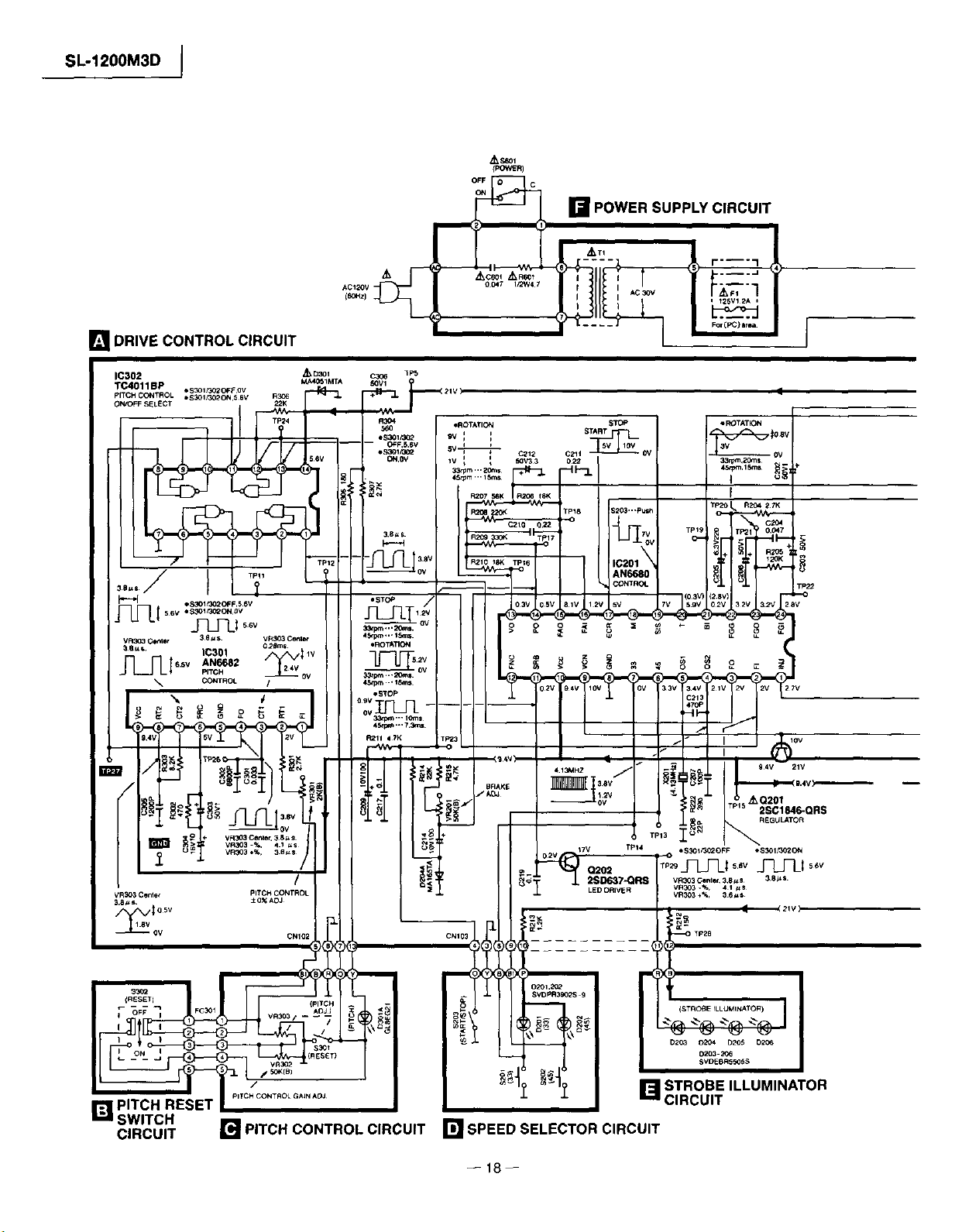
[] DRIVE CONTROL CIRCUIT
IC302
TC4011BP *S_I_O2OFFOv
pITCHCONTROL eS_I/302ON56V
OWO_SELECT
/_, S6Ol
{PO_R)
o_._._ [] POWERSUPPLYCIRCUIT
,
VR303Ce_ PITCH CONTROL
3.8=s ±O_AOJ
(RESETI
PITCHCONTROLGAiNAOJ
[] PITCH RESET
SWITCH
CIRCUIT
[] PITCH CONTROL CIRCUIT
CNI02
/
CNI03
SVDPR3902S 9
[] STROBE ILLUMINATOR
CIRCUIT
[] SPEED SELECTOR CIRCUIT
--18--
Page 19

[] REGULATOR CIRCUIT
I SL-1200M3D
--19--
[] OUTPUT CIRCUIT
C_I_PUT
Page 20
SL-1200M3D 1
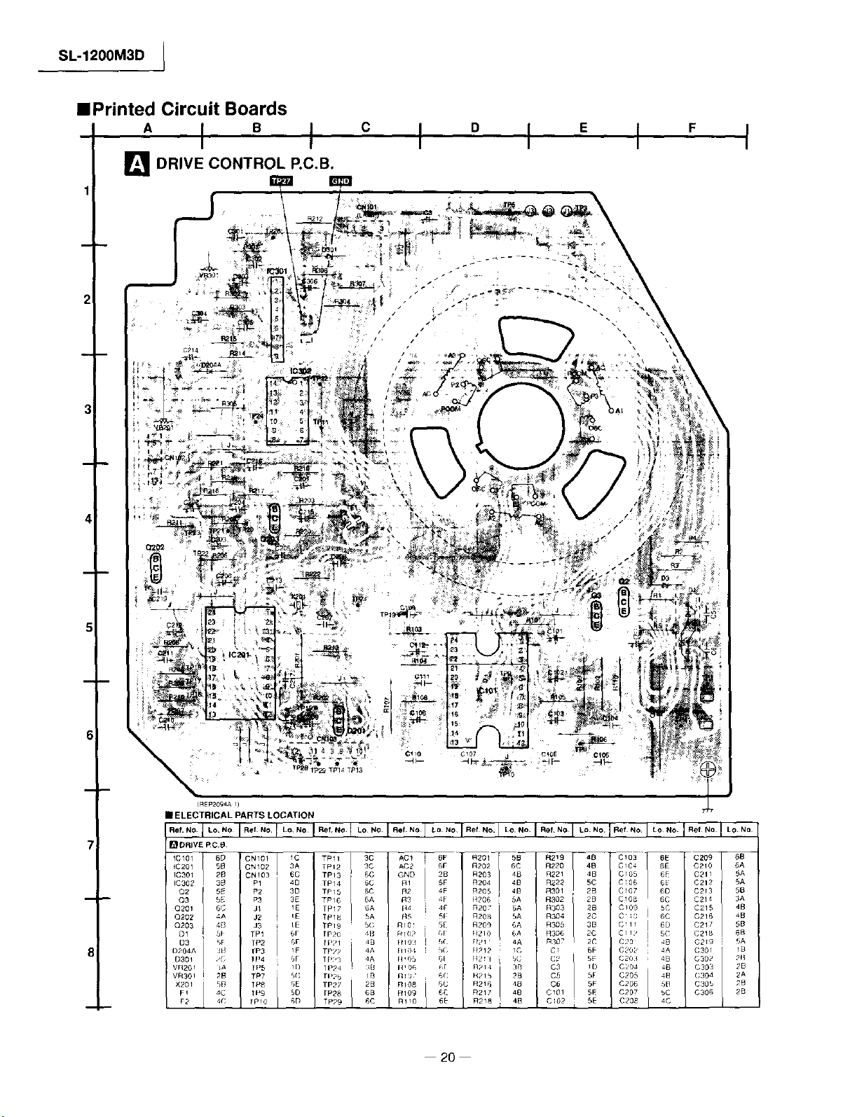
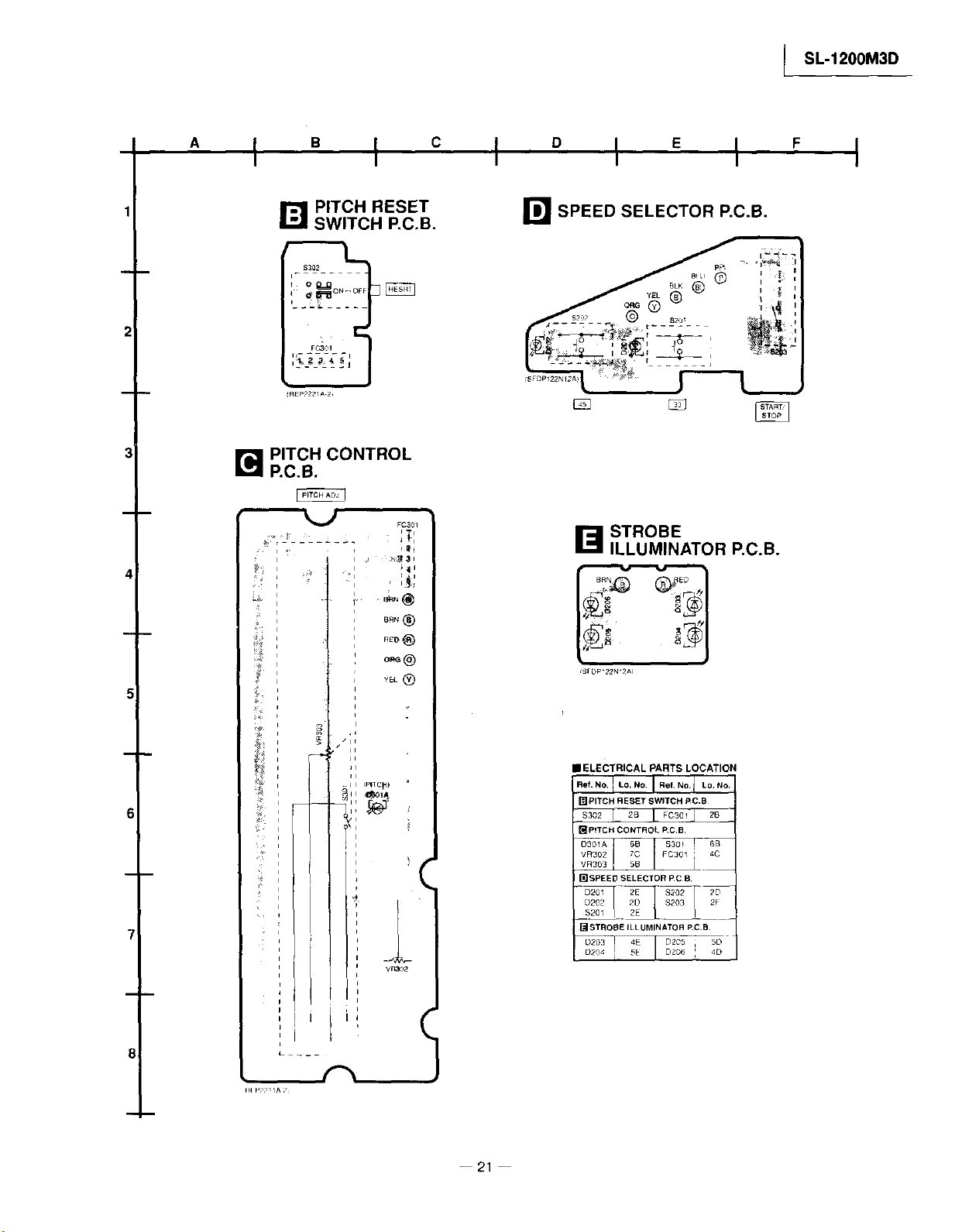
==Printed Circuit Boards
" I ° I
I_ DRIVE CONTROL P.C.B.
2i
C D E
F
_REP20_A I)
• ELECTRICAL PARTS LOCATION
i
20--
Page 21
I SL-1200M3D
" I '_ I c I ° I E I '_ I
I'_1 PITCH RESET []
SWITCH P.C.B.
m
FC301
i
_Ep22_lA 2_
B PITCH CONTROL
P.C.B.
B
FC301
:;7:
m
REIr)
SPEED SELECTOR P.C.B.
_'_ STROBE
ILLUMINATOR P.C.B.
7-
8
Hi Ppp_I^ ;,
- _ I rFfTC_)
I
VR3O_
(.
-- 21--
IELECTRICAL PARTS LOCATION
Ref. NO. I LO, NO. J Ref, NO, I Lo, No
ITI PITCH RESET _WlTCH PC,B
_P_TCH CONTROL _C,B
O301A
VR302 FC301 : 4C
[_SPEED SELECTOR PC B
" [3201 _-_2E $202 _D_
D202 22D I $203
STROBE ILLUMINATOR P.CB
_'_ D205 5D
D204 i 5E | D206 i 4D
Page 22

SL-1200M3D I
' I " I c I ° I E I F I
2I
i
POWER SUPPLY P.C.B.
r-J
r._ REGULATOR
P.C.B.
_REP2094A 1)
3
• ELECTRICAL PARTS LOCATION
I.:.2OwJ::uN:;L!::._Lo.No.
1_ REGULATOR P.C,B,
m OUTPUT P,C.B.
L+ 6D E 6D
_1°°1_'4°°
R- 6D
I_] OUTPUT P.C.B.
8
-- 22 --
Page 23

• Measurements and Adjustments
Notes: • Make the following adjustmentsafter replacing parts suchas IC's,Transistors,Diodes, etc.
• Condition ofthe set.
1.Power switch........................ ON
2 Pitch control......................... Center position
3.Speed selectorswitch............. 33 r.p.m.
• Instrumentsto be used
1Tester
2.Frequency counter
l SL-1200M3D
Adjustment Connection adjusted Procedure
Pitch control ± 0% VR301 2. Set the pitch controt knob to "0",
I (+} ... TP27
adjustment (-) ... Earth point (Fig. 1) (Indicator lights up.)
2 Pitch control gain (+} ... CN102 terminal _) VR302 3. Connect the testerto terminals,(_ and (_) of connector CN102
adjustment (-) ... CN102 terminal _) (Fig. 2) on the pitch control P.C.B. side.
3 Brake adjustment
Frequency counter 1. Connect the frequency counter and turn the power supply ON.
Tester 2, Pull out the connectorCN 102 of drive P.C.B.
Parts
3.Adjust VR301 so that the frequency is 262.08 kHz ± 0.05 kHz.
1. Set the pitch control knob to "0".
4, Adjust VR302 sothat the resistance value of the tester is
2,875 ± 0.25 kQ.
VR201 1.Adjust VR201 so that the rotation at 33 r.p.m, stops within
(Fig. 1) the angle of 30° - 210 ° after depressing the stop position.
• Alignment Points
Please refer to PrintedCircuit Board Diagram for test point locations.
pITCH CONTROl.
-t- 0% ADJUSTMENT
PITCH CONTROL
P.C.B.
DRIVE P,C B
Fig. 1
-- 23
BRAKE
ADJUSTMENT
oa_o
Fig. 2
0
YEL
=5
=6
=7
= 13
PITCHCONTROL
GAIN ADJIJSTMENT
Page 24

SL-1200M3D i
• Block Diagram
POSIT_+I
OETECTOR CO_IL +15_ TI S6O 1
,o+'_'+°,+, ,°,o
12 C2 AC .
AN66a0
CONTROL
_____X201 5 O SCI "_,___
z _T--_-_ Ol c-m_ _L-
4 0_C;2
•',+' °°++t_-#-z_t_.I
Q203 23 FGO II F_LT£R AMp :
o+o+.+o°+°+-- ++_-_+ _ , _ ++
-L + +p ,_-_S_m....... +, + t %6+TM + +
++,+I'__, + "",+° "-'-' : L+'o
_ -- 1o
l Io _P_+ oi++,+,,+oo I I i ! 1.+.1_
I _ i i ,_+i +,+)
I pH_S _ _ +C_L+-RG£ i _¢ vt-n FOI4 i _1 _--
I , ,_,+_, ,_+"' o++..
-- 14 4
v_p++, ,,
+ $202 $201
o+, ,,,+Co.gO_,_g_"
Z. J (+_ES_T)
24--
Page 25

IIIWiring Connection Diagram
Sd01
PL1
AC120V
[] REGULATOR
SUPPLY P.C.B.
laPOWER
P.C.B.
[] PITCH RESET
SWITCHP.C.B.
I
SL-1200M3D
B PITCH
CONTROL P.C.B.
I_l DRIVE CONTROL P.C.B.
Tl(Powe_ transiormer)
]STROBE
ILLUMINATOR RC.B.
CN103
-- 25 --
Page 26

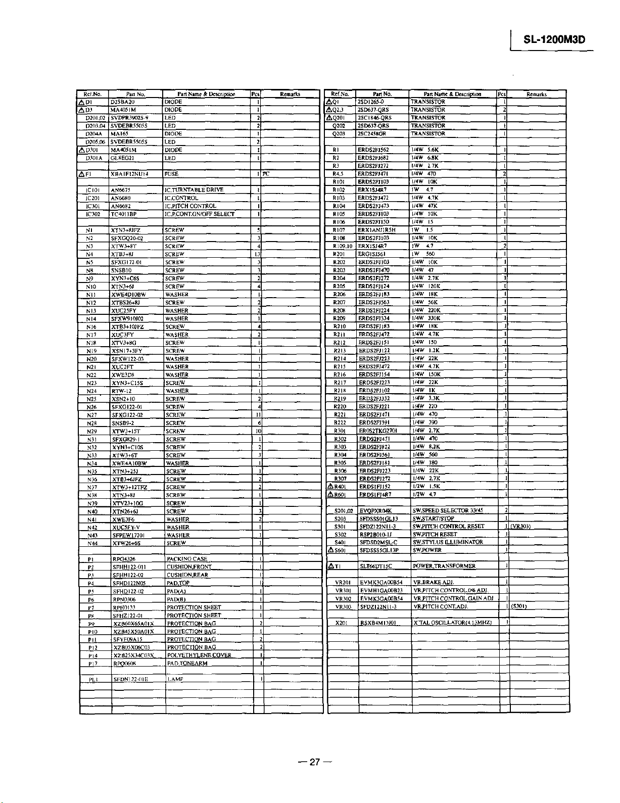
SL-1200M3D I
• Replacement Parts List
Notes: * IHI[J4jI1_[111_¢ll_ty[IUIl_l_,
Components identifiedby _ mark have special
characteristics important for safety.
Furthermore, special parts which have purposes of fire-
retardant (resistors), high-quality sound (capacitors),
low-noise (resistors), etc. are used.
When replacing any of components,be sure to use only
manufacture's specified parts shown in the parts list.
• All parts are supplied by MESA.
• The "<IA> <IB>" maarks in Remarks indicate language
of operating instructions.
<lA> : English
<IB> : Canadian French
Ref.No Pan NO part Name & De_'ri[xiea pcs Remarks
i SFADI22-OlA DUST COVER
2 R OSO(X)_ T;T RUBBER MAT
3 SFTEI72-OIZ TURNTABLE ASS'y
4 SFUM 172 053 'ANEL COVER
5 _FMGQ20-01 DRIVE COIL COVER
6 _FMG520-31A DRIVE COIL ASS'Y
7 _FMZI72-OIE FG COIL ASS'Y
8 _FMZQ2P, 01A _HAFT ASS'y
9 RFKN 12OOM3DP POWER SW KNOB ASS'Y
I0 SFKT015-_I BUTTON.START/STOP
I_ SFKT015-OIIE BUTI_N,SPEED SELF_TTOR (33)
12 $FKTOI5.021E BUITON,S PEED SELECTOR (45)
13 _FDJI22-ff2E WIRE ASS'Y
14 SFDII22_6E WIRE ASS'Y
15 ROKO942Z S COVER,STROBE ILLUMINATOR
16 SFQAI22-OI SPRING
17 RMR 1111A K BASE,OPERAqqON
18 SFUMI22-O3 CAM.POWER SWITCH
19 FUMOIS-I I SPACER J_ED
20 SFYB5 32 BALL
21 SFQA520 OI SPRING
22 SFKKI72 OI COVER.STYLUS ILLUMINATOR
23 SFXBI22-06 DRIVE BOSS
24 SFQAI72-01 SPRING
25 SFXJI72-OI pIN.LOCK CANCELER
26 SFQA520 011 SPRING
27 SFX0172-01-1 p[N_UIDE
28 SFUPI22-02E BRACKET,ILLUMINATOR
30 SFUP1224)3 pLATE,LOCK OPERATION
31 $FQA 122-02 SPRING
32 SFXII?2-O5 pIN
33 RMG0483 K RUBBER,DUST COV£R
35 FUPI22.09 HOLDERJ.ED
36 SFUPI22-OI !BRACKET_PITCHCONTROL
37 $FDJI22-04E WIRE ASS'Y
38 FUPI22-15-1 STOPPER.SPRING
40 RKM0101D S CABINET
41 FUM 172.04 ORNAMENT.ILLUMINATOR
44 FUPI22MI2E2 AC CORD ASS'Y
45 $FKTI22.02 KNOB_°ITCH CONTROL
46 RGHB]31 SI ORNAM ENT,p ITCH CONTROL
47 SFUZI22 OI IFELT
51 SFGC] 22-01 !RUBBER
53 SFAU 122-032 BOTTOM COVER B
54 FAU 122 022 BOT/-OM COVER A
55 RGNI655 K NAMEPLATE.
55 RGNI656 K NAMEPLATE
57 SFUPI22 233 _UPPORTER(A}
6_) SFGCI22-O4E INSULATOR
70 SFPRTI7201K RM REST
7] RFKN/21X)MK2A _RM BASE ASS'Y
73 SFPKDI22(B BRACKET.ARM BASE
74 SFPA B [7205 KNOB,ANTI.SKATING CONTROL
76 SFPCC3 I(X)5K HEAD SHELL
76 I REZIO37 I WIRE KIT
77 p AMIX20]K FONEARM ASS y
7X SFpW(;] 72(}] K BAI AN(TE Wlil(;l I I
7U SFI_R[ IH_CHK RM iJl:r
x¢) SFOAX2V I)3 _pRIN(;
Ref.No. Pan NO partName & De_xrip_ion
81 5FPABI3202 KNOB,UFI"
X2 _FPABI8201 K TONEARM FIXING PLA3_
g3 _FPJLI8202K }ILDAMPER
_4 SFPZBI220_ K pLATE
_5 SFI'ZBI2203 PLATE.ARM BASE COVER
x6 SFUM 170-06 SPACER.PHONO CORD
_7 FPZBI2204 CLAMpER,PHONO CORD
8_ RJL2FO31 BI 2 pHONO CORD
149 SFEL026_I El GROUND WIRE
90 SFPZBI7202 KNOB.ARM LOCK
91 N092 SPACER
92 RGU_SII S BIII'FON.pITCH CONT RESET
93 RMR0945 K pLATE,PITCH CONTROL RESET
94 RMXOI24 SPACER
9_ SFGZI22 {)21 RUBBER
9_ SFXW1724)32 SPACER,PITCH CONTROL
99 REZO_ 36 FLAT CABLE
101 SFIJZI22 04 SHEET
104 RMR I 112-K HELLSTAND
105 RQLC0142 T_CHNICS LABEL
AI RQT4912 -p O/I BOOK
AI RQT4913 C b'l BOOK
A2 RQAO149 WARRANTY CARD
A2 SQX71g3 WARRANTy CARD
A3 $FWE010 EP record ADAPTOR
A4 RHN26CO3 NLrr.c ARTR IDGE
A5 sr-CzvsRol SCREgLCARTRIDGE
A6 FPEV9801 SCRE_LCAKIRIDGE
A7 SFPEW9601 WASHER
A8 SFPZB3501 SHELL WEIGHT
A9 SFFWGI7202 AUXB.IARy WEIGHT
At0 SFKOI35 OI OVERHANG GAUGE
AI 1 RG$0OOSZ DISC SLIP SHEET ASSY
AI2 RQLC0142 TECHNICS LABEL
AI3 RQCB0391 S6RVICENTER LIST
AI3 ROCBC_32 S_RVICENTER LIST
ACI ECAI HM471S 50V 470U
C2 RCEI EU330BV 25v 33U
C3 ECEA I EKA22OB 25V 22U
_C5,6 ECQM 1223KZ3 125V 0.022U
C101 (3 RCI_IEU330BV 25V 33U
C10407 ECQVIHIIMIM3 5(IV 01U
C108 ECAIEMIOI 25V I_)U
CIO9,10 ECQVIHIO4JM3 50V II.IU
CIII ECQBIH562JF3 50V 56OOP
CII2 RCEIHKA4RTBG 50V 4,7U
C2Ol RC_I AKA330BG IOV 33U
C20"2,03 EC_AIHKSOI0 5OV IU
C204 ECQVIH473JM3 5OV 0.047U
C205 ECAOJM221 6.3V 220U
C206 ECI_A I HKS010 50V IU
C207 ECCRIHIOI K5 5OV 10Op
C208 ECCRI H220KU5 50V 22P
C209 RCEIAUI01BV ]0V IODU
C210,11 ECQVIH224JM3 50V 022U
C212 RCEIHKA3R3BG 50V 33U
C213 ECCR! H471K5 50V 47(_
C214 RC_IAUIOI BV 10V IC_U
P
PC
C215 ECEAIHKSOI0 50V IU
C216 RCEIAKA470BG IOV 47U
C217.19 ECFRIH[[MZF 50V O]U
C3(H ECQKI333GZ 125V B (133U
C3(12 ECQK 16_2GZ 125V 68(X)p
C3(13 EC6AIHKS(}]O 5OV IU
C3114 RCI_ICKA](W)BG 16V BIU
C305 ECQBIHt22JF3 50V 12(X)p
(731)5 ECEAI[I KSI)I(} 50V IU
_.C6OI F.CQU2 A 4_3M y I(XIV 0047U
CNI01 EMCSI)36_IL CONNECrOR(3P)
CN](12 EMCS046Oi CON NECI'ORI4PI
I'N]03 EMCS076tlL ('ON NE(_ORITP I
Pc Remark_
p.FC <IA>
PC <IB>
Pc
-- 26 --
Page 27
I SL-1200M3D
Ap30t
AFI
Rcl.No.
D201.02
D2IB._
D204A
D205,('_
D3OIA
ICIOI
1C201
]C301
1C302
NI
N2
N3
N4
N5
Ng
N9
NIO
Nil
NI2
NI3
NI4
N]6
N]7
N18
NI9
N20
N21
N22
N23
N24
N25 "
N26
N27
N2g
N29
N3I
N32
N33
N34
N35
N36
N37
N38
N39
N40
N41
N42
N43
Na,4
PI
P2
P3
P5
pC,
P7
p_
pIo
pII
pI2
p]4
pT7
pL t
Part No.
D2SBA20
MA4OSIM
SVDPR3902S 9
SVDEBR5505S
MAI65
SVDEBR5505S
MA4051M
GLSEG2I
XBAIF12NUI4
AN6675
AN6680
AN6682
TC4OIIBP
XTN3+SJFZ
SFXGQ2(_O2
XTW3÷8T
XTB3+SJ
SFXGI72 OI
SNSBI0
XYN3+C6S
XTN3+6J
XWE4DIOBW
XTBS26+8J
XUC25FY
SFXW910Jff/
XTB3+IOIFZ
XUC3FY
XTV3+SG
XSNI7+3FY
SFXWI22 03
XUC2FT
_WE3D8
XYN3+CISS
RTW-12
XSN2÷IO
_FXGI22-01
SFXGI22-02
SNSB9-2
XTW3+I5T
SFXG829-1
XYN3+CI(3_
XTW3+6T
XWE4AIOBW
XTN3÷25J
XTB3+6JFZ
XTW3+I2Tt_
XTN3÷81
KTV23+IOG
KTN26+_d
XWE3F6
XUC5Fy.V
SFFEWI7201
XTW26*6S
R_4326
SFHHI22 Oil
SFHHI22-02
_FHDI22N05
SFHD122 (}2
RPN0306
RPHO133
SFHZ]22-01
XZB6OX65A01 X
XZB45XS(IA01 X
SFYFOgAI5
XZBO5X06C03
XZB25X34C03X
RFQO6_X_
SFDNI22-(IIE
Pan Name&De_ri_io_
DIODE
DIODE
LED
LED
DIODE
LED
ID[ODE
LED
FUSE
!IC,TLrRNTABLE DRIVE
IC.CONTROL
IC.pITCH CONTROL
IC.I_CONT.ON/OFF SELECT
gCREW
_CREW
_CREW
SCREW
SCREW
SCREW
SCREW
SCREW
WASHER
SCREW
WASHER
WASHER
SCREW
WASHER
SCREW
SCREW
WASHER
WASHER
WASHER
SCREW
WASHER
SCREW
SCREW
SCREW
SCREW
SCREW
SCREW
SCREW
SCREW
WASHER
SCREW
SCREW
SCREW
SCREW
SCREW
SCREW
WASHER
WASHER
WASHER
SCREW
PACKING CASE
CUSHIONrFRONT
CUSH [ONrREAR
PADITOP
PAD_AI
PAD_)
pROTECTION SHEET
PROTECTION SHEET
PROTECTION BAG
PROTECTION BAG
pROTECTION BAG
pROTECTION BAG
POLYETHYLENE COVER
PAD_TONEARM
q.AMP
_s Rema_s
PC
ReLNo.
AQ_
AQ2,3
_Q2ol
Q2O',t
Q203
RI
R2
R3
R4,5
RIOt
RI02
RIO3
RIO4
RIO5
RI06
RIO7
RI08
RI09,10
R201
R202
R203
R204
R205
R2_
R207
R20g
R2_
R210
R211
R212
R213
R214
R215
R2)6
R217
R218
R219
R220
R221
R222
R301
R302
R_3
113O1
R_5
*,r_ot
'_,$60]
ATI
R3_
R3_
$20t.¢(2
$203
S30I
S302
$4OI
VR201
VR3{II
VR ?_)2
VR303
X201
par, NO.
2SD1265_
2SD637-QRS
2SC1846-QRS
2SD637.QRS
2SC245_0R
ERDS2FJ562
ERDS2FJ682
ERDS2FI272
ERDS2FJ47t
ERDS2FJIO3
ERXISJ4R7
ERDS2FJ472
ERDS2FJ473
ERDS2FJI03
ERDS2FJISO
ERXIANJIRSH
ERDS2FJI03
ERXISJCR7
ERGISJ561
ERDS2FJI03
ERDS2FJ470
ERDS2FJ272
ERDS2FJ[24
ERDS2FJ[83
ERDS2FJ563
ERDS2FJ224
ERDS2FJ334
ERDS2FJ]83
ERDS2FJ472
ERDS2FJI51
ERDS2FJI22
ERDS2FJ223
ERDS2FJ472
FRDS2FJI54
ERDS2FJ223
ERDS2FJ[02
ERDS2FJ332
ERDS2FJ221
ERDS2FJ471
ERDS2FJ391
ER0_2TKG2701
ERDS2FJ471
ERDS2FJS_2
ERDS2FJ56]
ERDS2FJI_I
ERDS2FJ223
ERDS2FJ272
ERDStFJI52
ERDS[FJ4R7
EVQPXRt_K
SFDSSS01GLI3
SFDZI22NI 1-3
RSP2B0[0-1J
SFDSD2MSL-C
SFDSSSSGLI3P
SLT66DTISC
EVMK3GAOOB54
EVMHIGAOOB23
EVMK3GAOOB54
SFDZI22Nll-3
RSXB4MI3JO]
Pan Name & Description
TRANSISTOR
TRANSISTOR
TRANSISTOR
'IRANSISTOR
TRANSISTOR
I/4W 5.6K
I/4W 6.8K
1/4w 27K
II4W 470
I/4W [OK
IW 4.7
I/4W 4.7K
I/4W 47K
1/4W I0K
I/4W 15
I W 1,5
1/4W 10K
IW 47
IW 560
I/4W 10K
114W 47
I/4W 2.7K
I/4W 120K
I/4W 18K
I/4W 56K
114W 220K
I/4W 330K
l/4W IBK
l/4W 4,7K
I/4W 150
114W 1.2K
[/4W 22K
U4W 4.7K
I/4W [50K
I/'IW 22K
I/4W IK
I/4W 3,3K
t/4W 220
II4W 470
[14W 390
II4W 2,7K
I/4W 470
l/4W 8.2K
I/4W 560
I/4W 180
I/4W 22K
1/4W 2.7K
I_W 1.5K
]/2W 4.7
SW.SPEED S_LF.C/_R 33/45
SW#TARTt S'I'Op
SW.PITCH CONTROL RESET
SW,PlTCH RESET
SW,STYLUS ILLUMINATOR
SW.FOWER
FOWER,'I_ANSFORMER
VR,BRAKE ADJ
VR.PITCH CONTROL.G% ADJ
VR,PITCH CONTROL GAIN AD/
VR.PITC H CONT.ADJ
X_FAL OSCILLATOR(4 13MHZ /
Pcs
Rema_s
(VR303)
:S301)
-- 27 --
Page 28

SL-1200M3D I
lCabinet Parts Location
0
@
2 RGSOT_)_ T/T RUBBER MAT t 9 RFKN ! 2ODM3DP pOWER SW KNOB A$$'y I 16 SFQAI22 O_ SPRING
3 SFTEI72 OIZ TURNTABi,E ASS+y 1 IO SFKTOI 5-(_SI BU ]'/'ON.START/STOp I l? RMRIIIIA-K BASE,OPER ATION
4 SFUMI72.O53 PANEL COVER i I1 SFKTOISX)IIE BUTTON3PEED SELECTOR(3] j I 18 SFUMI22/)3 CAM,FOWER SWITCH /
I Ret.No pa_l NO. part Name & Dcscrilxion pc_ RcfNo panNo part Name & Descript ion pc_ Rcf.No part No par( Name & Dcscdption pCS
6 SFMG5211 31A I 13 SFDJ 122 O2E WIRE ASS'Y I 20 SFYB5 32
I SFADI22-OIA DRIVE COll. ASS'YDUST COVER I 8 SFMZQ2fl OIA SHAFTASS'Y I 15 RGK(_42Z-$ BALI.COVER'STROB E ILLUMINATOR
5 SFM(;Q20 OI DRIVE COIL COVER I 12 SFKTOI5 O2}E B UTTON.S PEED S ELECTOR(45J I 19 $FUMOIS.II SPACER,LED
-- 28 --
Page 29
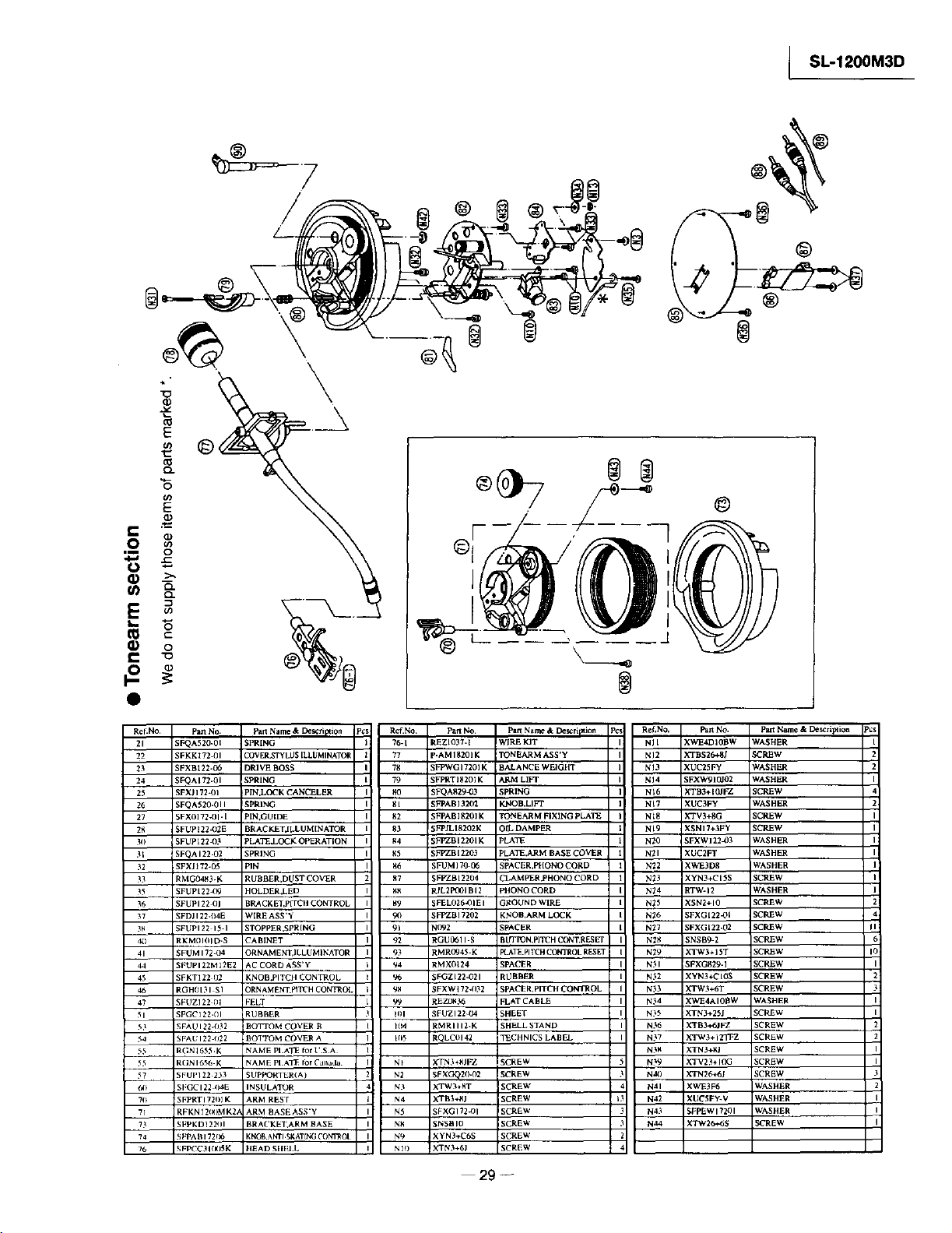
©
SL-1200M3D
©
Re_No. Pan No. part Name & Descfi p_ion R_ENo. Part No. PaM Name & Desc ri_ioa Pcs: Ref. NO, PaR NO.
21 SFQA520-01 SPRING 76-[ REZlO3"L_ WIRE KIT NIl XWE4DIOBW
22 SFKKI72-01 COV ER.STy LU$ [LLUMliqATO_ 77 -AMI820]K TONEARM ASS'Y II NI2 XTBS26+SJ
23 SFXBI22-06 DRIVE BOSS 78 SFPWG]7201 K BALANCE WEIGW[" N J3 XUC25Fy
24 SFQAI72.01 SPRING 79 FPRT]820IK _M LIFT NI4 SFXW910JO2
25 SFXJ]72-01 PIN,LOCK CANCELER 80 SFQA829_3 SpRING NI6 XTB3÷[OJI _Z
26 SFQA520.OI I SPRING 81 SFPAB]32(TZ KNOB.LIFT N_7 XUC3FY
27 SFXOI72d)I- [ PIN,GUIDE 82 FPAB]I_201K TONEARM FIXING pLATE N_8 XTV3+SG
28 SFLrPI22_E BRACY.ETJLLUMINATOR 83 FPJLIS/O2K OgL DAMPER N_9 XSN]7+3FY
3O SFUPI22_3 PLATiLLOC K OPERATION _4 FFZB[2201K PLATE N20 SFXW]21_93
31 SFQAI22-02 SPRING _5 SFPZBI2203 PLATE,ARM BASE COVER N21 XUC2FT
32 SFXJ172.05 PIN _6 FUM] 7(_P,6 SPACER,PHONO CORD N22 _WE3D8
35 RMGO4_3.K RUBBER.DUST COVER _7 FPZBI2204 CLAMPER.PHONO CORD N_3 _yN3+CISS
35 SFUPI22 (_9 HOLDER.LED I;8 RIL2P_OI BI 2 PHONO CORD N_4 :('TW. 12
36 SFUPI22 OI BRACK E'I ,pITCH CONTROL 89 FEL026_31E I GROUND WIRE N_5 _SN2+IO
37 SFDJI22.O4E WIRE ASS'Y 90 SFPZBI7202 KNOB.ARM LOCK N_6 _FXG[22_)[
3_ SFUPI22 15.1 STOppER.SpR[NG 91 NO92 SPACER N_7 _FXG [ 22.02
4(i RKM/II()I D.S _AB]NET 92 [GU061 I.S BUTION.PITCH C_'_R ESET N_ gNSBg-2
,11 SFUMI72 O4 _RNAMENT,ILLUMI_ATOR 93 RMRO945.K FLAT_.PITCH CONTROL RE3 E'f N_9 XTW3+IST
44 SEUPI22M 12E_ _C CORD ASSAY _4 RMXO_24 SPACER N_I _EXG829. I
4_ :FKT122 112 gNOB.PITCH CONTROL 96 ;FGZI22-021 RUBBER N_2 ×YN3+CIOS
46 RGH(II31 $1 _R N AM ENT.pITC H CONTROL 9_ IFXWi72.O32 SPACER,pITCH CONTROL N_3 XTW3 +6T
47 SFUZI22 Ill _ELT 99 REZO836 FLAT CABLE N_4 KWE4AIOBW
51 SFGC122.111 ;RUS]BER IIII SFUZI22kO4 SHEET N_5 XTN3+25J
53 SFAUI22-O32 BOTTOM COVER B 1114 _MRIII2-K SHELL STAND N_6 XTB3+6|FZ
54 S[_.UI22 O_2 BOI"!'OM COVER A 11_5 RQLC(II42 TECHNICS LABEL N_7 XTW 3 + 12'YFZ
_ RGN 165_ .K _AME PLATE _or USA N_ XTN3+I_J
55 RGNI6'i6 K _AM E PLATE Ior C_l_ada N_ XTN3+SJF'Z SCREW N_9 XTV23+IOG
_7 SFUP122 233 _Up_offI_R( A ) N2 SFXGQ20-O2 SCREW N,I_) XTN 26+6_
_) SFGCI22 O4E INSULATOR N3 XTW3+_T _CREW N41 XWE3F6
70 SFPRTI72()I K ARMREST N4 X'FB3÷_;J _CREW 13 N42 XUCSF_V
7] RFKNI21_MK_A ARM BASEASS'Y N_ _FXGI?2_)I _CREW N43 SFPEWI?201
73 SFPKD1221_1 BRACKE I_ARM BASE N8 SNSBIO i SCREW N44 XTW26_6S
74 SFPABI721)6 KgOB.ANTI SK A$[NG CONTROl N9 XYN3_'6S SCREW
_6 _;FPf'C3 HKI_K HEAD SHEII. NIl) X'TN3÷6J SCREW
29--
par_Name & De scriF_ioa
€/ASHER
/CREW
_VASHF¢R
.VASHER
_CREW
WASHER
SCREW
SCP,_W
WASHIER
WASHER
WASHER
SCREW
WASHER
SCREW
SCP_W
SCREW
SCREW
SCREW
SCREW
SCREW
SCREW
WASHER
SCREW
SCREW
SCREW
SCREW
SCREW
SCREW
WASHER
WASHER
WASHER
SCREW
Page 30

SL-1200M3D J
• Packaging
1:'4
(T/T RUBBER MAT)
P9
"P7
<_12
P3
AI, A2, A13
A3
Pa_ NO.
Rl_rr4912 P O/] BOOK
RQT4913 12 _I BOOK
RQA0149 WARRANTY CARD
SQXTI _3 WARRANTy CARD
SFWEOIO EP r_ord ADAPTOR
RHN26_)3 NLrI'£'ARTR]DGE
SFCZV_801 $CREV_CARTrIDGE
SFPEVg'g01 SCRE_CARTR[DGE
SFPEWgN) I WASHER
SFPZB35(II SHEt,L WEIGHT
SFPWGI?202 AUXILIARY WEIGHT
SFKIII35-OI OVERHANG GAUGE
RGS0_SZ DISC SLIP SHEET ASSY
RQLC01 _ I_CHNICS LABEL
R1_'_)391 _ERV[CENTER LIST
_ERV[CENTER LIST
P1
(HEAD SHELL)
Pan No. Pan Name & l_criptton
RPG4326 )ACKING CASE
SFHHI22 (111 _USH[ON,FRONT
5FHHI22-02 _USHION,REAR
SFHD122N05 _AD TOp
SFHDI22 02 _AD(A)
RPN0306 _AD(B)
RPH0133 _ROTECTION SHEET
SFHZI22-OI )ROTECTION SHEET
XZB6OX65A(II_ )ROrECTION BAG
XZB45XSOAOI_ )ROTECTION BAG
SFyFOgA 15 )ROTEC'I'ION BAG
XZBt)SXO6C03 _ROTECTION BAG
XZB25X34C03X _OLYETHyLENE COVER
RFQO6t_ _AD TONEARM
30 w
AIO
A8
A9
Printed in Japan
K990301850YH/AM
Page 31

I SL-1200M3D
 Loading...