

Page 1

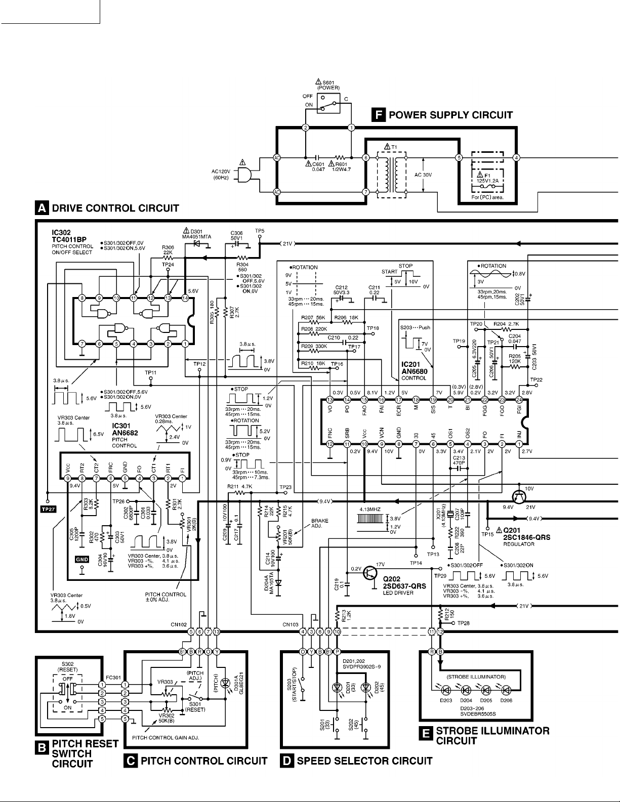
SL-1200M3D
Schematic Diagram
Notes:
The voltage value and waveforms are the reference voltage of this measured by DC electronic voltmeter (high impedance)
and oscilloscope on the basis of chasssis.
Accordingly, there may arise some errors in the voltage values and waveforms depending upon the internal impedance of the
tester or the measuring unit.
Important safety notice:
Components identified by
use only manufacture’s specified parts.
NO MARK: Voltage when at a stop
( ) : Voltage during rotation
•S201 :
•S202 :
•S203 :
•S301 :
•S302 :
•S401 :
•S601 :
•VR201 :
•VR301 :
•VR302 :
•VR303 :
SPEED SELECTOR (33 rpm) switch.
SPEED SELECTOR (45 rpm) switch.
START/STOP switch.
PITCH CONTROL RESET switch in “OFF” position. (Interlocked with VR303)
PITCH RESET switch in “OFF” position.
STYLUS ILLUMINATOR switch in “ON” position.
POWER switch in “ON” position.
BRAKE ADJUSTMENT VR.
PITCH CONTROL ± 0% ADJUSTMENT VR.
PITCH CONTROL GAIN ADJUSTMENT VR.
PITCH CONTROL ADJUSTMENT VR. (Interlocked wwith S301)
!
mark have special characteristics important for safety. When replacing any of these components,
: +B Line
Type Illustration of IC’s, Transistors and Diodes
. 17 .
Page 2
SL-1200M3D
. 18 .
Page 3

SL-1200M3D
. 19 .
Page 4
SL-1200M3D
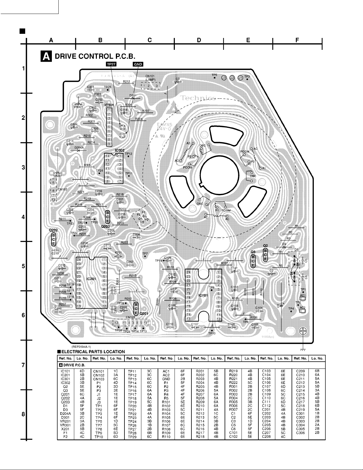
Printed Circuit Boards
. 20 .
Page 5

SL-1200M3D
. 21 .
Page 6

SL-1200M3D
. 22 .
Page 7

Measurements and Adjustments
Notes:
• Make the following adjustments after replacing parts such as IC’s, Transistors, Diodes, etc.
• Condition of the set.
1.Power switch……………………ON
2.Pitch control…………………….Center position
3.Speed selector switch………….33 r.p.m.
• Instruments to be used
1.Tester
2.Frequency counter
SL-1200M3D
Adjustment
2
Pitch control ± 0%
adjustment
Pitch control gain
adjustment
Brake adjustment
1
3
Connection
Frequency counter
(+) … TP27
(–) … Earth point
Tester
(+) … CN102 terminal
(–) … CN102 terminal
Parts
adjusted
VR301
(Fig. 1)
VR302
(Fig. 2)
VR201
(Fig. 1)
Alignment Points
Please refer to Printed Circuit Board Diagram for test point locations.
Procedure
1. Connect the frequency counter and turn the power supply ON.
2. Set the pitch control knob to “0”.
(Indicator lights up.)
3. Adjust VR301 so that the frequency is 262.08 kHz ± 0.05 kHz.
1. Set the pitch control knob to “0”.
2. Pull out the connector CN102 of drive P.C.B.
3. Connect the tester to terminals, and of connector CN102
on the pitch control P.C.B. side.
4. Adjust VR302 so that the resistance value of the tester is
2.875 ± 0.25 kΩ.
1. Adjust VR201 so that the rotation at 33 r.p.m. stops within
the angle of 30° ~ 210° after depressing the stop position.
. 23 .
Page 8

SL-1200M3D
Block Diagram
. 24 .
Page 9

Wiring Connection Diagram
SL-1200M3D
. 25 .
Page 10

SL-1200M3D
Replacement Parts List
Notes: *
Important safety notice:
Components identified by mark have special
!
characteristics important for safety.
Furthermore, special parts which have purposes of fireretardant (resistors), high-quality sound (capacitors),
low-noise (resistors), etc. are used.
When replacing any of components,be sure to use only
manufacture’s specified parts shown in the parts list.
All parts are supplied by MESA.
*
The “<IA> <IB>” maarks in Remarks indicate language
*
of operating instructions.
<IA> : English
<IB> : Canadian French
Ref.No.
1
2
3
4
5
6
7
8
9
10
11
12
13
14
15
16
17
18
19
20
21
22
23
24
25
26
27
28
30
31
32
33
35
36
37
38
40
41
44
45
46
47
51
53
54
55
55
57
60
70
71
73
74
76
76-1
77
78
79
80
Part No.
SFAD122-01A
RGS0008
SFTE172-01Z
SFUM172-053
SFMGQ20-01
SFMG520-31A
SFMZ172-01E
SFMZQ20-01A
RFKN1200M3DP
SFKT015-061
SFKT015-011E
SFKT015-021E
SFDJ122-02E
SFDJ122-06E
RGK0942Z-S
SFQA122-01
RMR1111A-K
SFUM122-03
SFUM015-11
SFYB5-32
SFQA520-01
SFKK172-01
SFXB122-06
SFQA172-01
SFXJ172-01
SFQA520-011
SFX0172-01-1
SFUP122-02E
SFUP122-03
SFQA122-02
SFXJ172-05
RMG0483-K
SFUP122-09
SFUP122-01
SFDJ122-04E
SFUP122-15-1
RKM0101D-S
SFUM172-04
SFUP122M12E2
SFKT122-02
RGH0131-S1
SFUZ122-01
SFGC122-01
SFAU122-032
SFAU122-022
RGN1655-K
RGN1656-K
SFUP122-233
SFGC122-04E
SFPRT17201K
RFKN1200MK2A
SFPKD12201
SFPAB17206
SFPCC31005K
REZ1037-1
P-AM18201K
SFPWG17201K
SFPRT18201K
SFQA829-03
Part Name & Description Pcs Remarks
DUST COVER
T/T RUBBER MAT
TURNTABLE ASS’Y
PANEL COVER
DRIVE COIL COVER
DRIVE COIL ASS’Y
FG COIL ASS’Y
SHAFT ASS’Y
POWER SW KNOB ASS’Y
BUTTON,START/STOP
BUTTON,SPEED SELECTOR(33)
BUTTON,SPEED SELECTOR(45)
WIRE ASS’Y
WIRE ASS’Y
COVER,STROBE ILLUMINATOR
SPRING
BASE,OPERATION
CAM,POWER SWITCH
SPACER,LED
BALL
SPRING
COVER,STYLUS ILLUMINATOR
DRIVE BOSS
SPRING
PIN,LOCK CANCELER
SPRING
PIN,GUIDE
BRACKET,ILLUMINATOR
PLATE,LOCK OPERATION
SPRING
PIN
RUBBER,DUST COVER
HOLDER,LED
BRACKET,PITCH CONTROL
WIRE ASS’Y
STOPPER,SPRING
CABINET
ORNAMENT,ILLUMINATOR
AC CORD ASS’Y
KNOB,PITCH CONTROL
ORNAMENT,PITCH CONTROL
FELT
RUBBER
BOTTOM COVER B
BOTTOM COVER A
NAME PLATE
NAME PLATE
SUPPORTER(A)
INSULATOR
ARM REST
ARM BASE ASS’Y
BRACKET,ARM BASE
KNOB,ANTI-SKATING CONTROL
HEAD SHELL
WIRE KIT
TONEARM ASS’Y
BALANCE WEIGHT
ARM LIFT
SPRING
Ref.No.
81
82
83
84
85
86
87
88
89
90
91
92
93
94
96
1
1
1
1
1
1
1
1
1
1
1
1
1
1
1
1
1
1
2
1
1
1
1
1
1
1
1
1
1
1
1
2
1
1
1
1
1
1
1
1
1
1
3
1
1
P
1
PC
1
2
4
1
1
1
1
1
1
1
1
1
1
98
99
101
104
105
A1
A1
A2
A2
A3
A4
A5
A6
A7
A8
A9
A10
A11
A12
A13
A13
C1
C2
C3
C5,6
C101-03
C104-07
C108
C109,10
C111
C112
C201
C202,03
C204
C205
C206
C207
C208
C209
C210,11
C212
C213
C214
C215
C216
C217-19
C301
C302
C303
C304
C305
C306
C601
CN101
CN102
CN103
Part No.
SFPAB13202
SFPAB18201K
SFPJL18202K
SFPZB12201K
SFPZB12203
SFUM170-06
SFPZB12204
RJL2P001B12
SFEL026-01E1
SFPZB17202
N092
RGU0611-S
RMR0945-K
RMX0124
SFGZ122-021
SFXW172-032
REZ0836
SFUZ122-04
RMR1112-K
RQLC0142
RQT4912-P
RQT4913-C
RQA0149
SQX7183
SFWE010
RHN26003
SFCZV8801
SFPEV9801
SFPEW9601
SFPZB3501
SFPWG17202
SFK0135-01
RGS0005Z
RQLC0142
RQCB0391
RQCB0832
ECA1HM471S
RCE1EU330BV
ECEA1EKA220B
ECQM1223KZ3
RCE1EU330BV
ECQV1H104JM3
ECA1EM101
ECQV1H104JM3
ECQB1H562JF3
RCE1HKA4R7BG
RCE1AKA330BG
ECEA1HKS010
ECQV1H473JM3
ECA0JM221
ECEA1HKS010
ECCR1H101K5
ECCR1H220KU5
RCE1AU101BV
ECQV1H224JM3
RCE1HKA3R3BG
ECCR1H471K5
RCE1AU101BV
ECEA1HKS010
RCE1AKA470BG
ECFR1H104ZF
ECQK1333GZ
ECQK1682GZ
ECEA1HKS010
RCE1CKA100BG
ECQB1H122JF3
ECEA1HKS010
ECQU2A473MY
EMCS0360L
EMCS0460L
EMCS0760L
Part Name & Description
KNOB,LIFT
TONEARM FIXING PLATE
OIL DAMPER
PLATE
PLATE,ARM BASE COVER
SPACER,PHONO CORD
CLAMPER,PHONO CORD
PHONO CORD
GROUND WIRE
KNOB,ARM LOCK
SPACER
BUTTON,PITCH CONT.RESET
PLATE,PITCH CONTROL RESET
SPACER
RUBBER
SPACER,PITCH CONTROL
FLAT CABLE
SHEET
SHELL STAND
TECHNICS LABEL
O/I BOOK
O/I BOOK
WARRANTY CARD
WARRANTY CARD
EP record ADAPTOR
NUT,CARTRIDGE
SCREW,CARTRIDGE
SCREW,CARTRIDGE
WASHER
SHELL WEIGHT
AUXILIARY WEIGHT
OVERHANG GAUGE
DISC SLIP SHEET ASSY
TECHNICS LABEL
SERVICENTER LIST
SERVICENTER LIST
50V 470U
25V 33U
25V 22U
125V 0.022U
25V 33U
50V 0.1U
25V 100U
50V 0.1U
50V 5600P
50V 4.7U
10V 33U
50V 1U
50V 0.047U
6.3V 220U
50V 1U
50V 100P
50V 22P
10V 100U
50V 0.22U
50V 3.3U
50V 470P
10V 100U
50V 1U
10V 47U
50V 0.1U
125V 0.033U
125V 6800P
50V 1U
16V 10U
50V 1200P
50V 1U
100V 0.047U
CONNECTOR(3P)
CONNECTOR(4P)
CONNECTOR(7P)
Pcs
1
1
1
1
1
1
1
1
1
1
1
1
1
1
1
1
1
1
1
1
1
1
1
1
1
2
2
2
2
1
1
1
1
1
1
1
1
1
1
2
3
4
1
2
1
1
1
2
1
1
1
1
1
1
2
1
1
1
1
1
3
1
1
1
1
1
1
1
1
1
1
P,PC <IA>
PC <IB>
P
PC
P
PC
Remarks
. 26 .
Page 11

SL-1200M3D
Ref.No.
D1
D3
D201,02
D203,04
D204A
D205,06
D301
D301A
F1
IC101
IC201
IC301
IC302
N1
N2
N3
N4
N5
N8
N9
N10
N11
N12
N13
N14
N16
N17
N18
N19
N20
N21
N22
N23
N24
N25
N26
N27
N28
N29
N31
N32
N33
N34
N35
N36
N37
N38
N39
N40
N41
N42
N43
N44
P1
P2
P3
P4
P5
P6
P7
P8
P9
P10
P11
P12
P14
P17
PL1
Part No. Part Name & Description Pcs Remarks
D2SBA20
MA4051M
SVDPR3902S-9
SVDEBR5505S
MA165
SVDEBR5505S
MA4051M
GL8EG21
XBA1F12NU14
AN6675
AN6680
AN6682
TC4011BP
XTN3+8JFZ
SFXGQ20-02
XTW3+8T
XTB3+8J
SFXG172-01
SNSB10
XYN3+C6S
XTN3+6J
XWE4D10BW
XTBS26+8J
XUC25FY
SFXW910J02
XTB3+10JFZ
XUC3FY
XTV3+8G
XSN17+3FY
SFXW122-03
XUC2FT
XWE3D8
XYN3+C15S
RTW-12
XSN2+10
SFXG122-01
SFXG122-02
SNSB9-2
XTW3+15T
SFXG829-1
XYN3+C10S
XTW3+6T
XWE4A10BW
XTN3+25J
XTB3+6JFZ
XTW3+12TFZ
XTN3+8J
XTV23+10G
XTN26+6J
XWE3F6
XUC5FY-V
SFPEW17201
XTW26+6S
RPG4326
SFHH122-011
SFHH122-02
SFHD122N05
SFHD122-02
RPN0306
RPH0133
SFHZ122-01
XZB60X65A01X
XZB45X50A01X
SFYF09A15
XZB05X06C03
XZB25X34C03X
RPQ0608
SFDN122-01E
DIODE
DIODE
LED
LED
DIODE
LED
DIODE
LED
FUSE
IC,TURNTABLE DRIVE
IC,CONTROL
IC,PITCH CONTROL
IC,P.CONT.ON/OFF SELECT
SCREW
SCREW
SCREW
SCREW
SCREW
SCREW
SCREW
SCREW
WASHER
SCREW
WASHER
WASHER
SCREW
WASHER
SCREW
SCREW
WASHER
WASHER
WASHER
SCREW
WASHER
SCREW
SCREW
SCREW
SCREW
SCREW
SCREW
SCREW
SCREW
WASHER
SCREW
SCREW
SCREW
SCREW
SCREW
SCREW
WASHER
WASHER
WASHER
SCREW
PACKING CASE
CUSHION,FRONT
CUSHION,REAR
PAD,TOP
PAD(A)
PAD(B)
PROTECTION SHEET
PROTECTION SHEET
PROTECTION BAG
PROTECTION BAG
PROTECTION BAG
PROTECTION BAG
POLYETHYLENE COVER
PAD,TONEARM
LAMP
1
1
2
2
1
2
1
1
1
1
1
1
1
5
3
4
13
3
3
2
4
1
2
2
1
4
2
1
1
1
1
1
1
1
2
4
11
6
10
1
2
3
1
1
2
2
1
1
3
2
1
1
1
1
1
1
1
1
1
1
1
2
1
2
2
1
1
1
Ref.No.
Q1
Q2,3
Q201
Q202
Q203
R1
R2
PC
R3
R4,5
R101
R102
R103
R104
R105
R106
R107
R108
R109,10
R201
R202
R203
R204
R205
R206
R207
R208
R209
R210
R211
R212
R213
R214
R215
R216
R217
R218
R219
R220
R221
R222
R301
R302
R303
R304
R305
R306
R307
R401
R601
S201,02
S203
S301
S302
S401
S601
T1
VR201
VR301
VR302
VR303
X201
Part No. Part Name & Description Pcs Remarks
2SD1265-0
2SD637-QRS
2SC1846-QRS
2SD637-QRS
2SC2458GR
ERDS2FJ562
ERDS2FJ682
ERDS2FJ272
ERDS2FJ471
ERDS2FJ103
ERX1SJ4R7
ERDS2FJ472
ERDS2FJ473
ERDS2FJ103
ERDS2FJ150
ERX1ANJ1R5H
ERDS2FJ103
ERX1SJ4R7
ERG1SJ561
ERDS2FJ103
ERDS2FJ470
ERDS2FJ272
ERDS2FJ124
ERDS2FJ183
ERDS2FJ563
ERDS2FJ224
ERDS2FJ334
ERDS2FJ183
ERDS2FJ472
ERDS2FJ151
ERDS2FJ122
ERDS2FJ223
ERDS2FJ472
ERDS2FJ154
ERDS2FJ223
ERDS2FJ102
ERDS2FJ332
ERDS2FJ221
ERDS2FJ471
ERDS2FJ391
ER0S2TKG2701
ERDS2FJ471
ERDS2FJ822
ERDS2FJ561
ERDS2FJ181
ERDS2FJ223
ERDS2FJ272
ERDS1FJ152
ERDS1FJ4R7
EVQPXR04K
SFDSSS01GL13
SFDZ122N11-3
RSP2B010-1J
SFDSD2MSL-C
SFDSSS5GL13P
SLT66DT15C
EVMK3GA00B54
EVMH1GA00B23
EVMK3GA00B54
SFDZ122N11-3
RSXB4M13J01
TRANSISTOR
TRANSISTOR
TRANSISTOR
TRANSISTOR
TRANSISTOR
1/4W 5.6K
1/4W 6.8K
1/4W 2.7K
1/4W 470
1/4W 10K
1W 4.7
1/4W 4.7K
1/4W 47K
1/4W 10K
1/4W 15
1W 1.5
1/4W 10K
1W 4.7
1W 560
1/4W 10K
1/4W 47
1/4W 2.7K
1/4W 120K
1/4W 18K
1/4W 56K
1/4W 220K
1/4W 330K
1/4W 18K
1/4W 4.7K
1/4W 150
1/4W 1.2K
1/4W 22K
1/4W 4.7K
1/4W 150K
1/4W 22K
1/4W 1K
1/4W 3.3K
1/4W 220
1/4W 470
1/4W 390
1/4W 2.7K
1/4W 470
1/4W 8.2K
1/4W 560
1/4W 180
1/4W 22K
1/4W 2.7K
1/2W 1.5K
1/2W 4.7
SW,SPEED SELECTOR 33/45
SW,START/STOP
SW,PITCH CONTROL RESET
SW,PITCH RESET
SW,STYLUS ILLUMINATOR
SW,POWER
POWER,TRANSFORMER
VR,BRAKE ADJ.
VR,PITCH CONTROL,0% ADJ.
VR,PITCH CONTROL GAIN ADJ
VR,PITCH CONT.ADJ.
X’TAL OSCILLATOR(4.13MHZ)
1
2
1
1
1
1
1
1
2
1
1
1
1
1
1
1
1
2
1
1
1
1
1
1
1
1
1
1
1
1
1
1
1
1
1
1
1
1
1
1
1
1
1
1
1
1
1
1
1
2
1
1
1
1
1
1
1
1
1
1
1
(VR303)
(S301)
. 27 .
Page 12

SL-1200M3D
Cabinet Parts Location
Ref.No.
1
2
3
4
5
6
Part No. Part Name & Description Pcs
SFAD122-01A
RGS0008
SFTE172-01Z
SFUM172-053
SFMGQ20-01
SFMG520-31A
DUST COVER
T/T RUBBER MAT
TURNTABLE ASS’Y
PANEL COVER
DRIVE COIL COVER
DRIVE COIL ASS’Y
Ref.No.
7
1
8
1
9
1
10
1
11
1
12
1
13
Part No. Part Name & Description Pcs
SFMZ172-01E
SFMZQ20-01A
RFKN1200M3DP
SFKT015-061
SFKT015-011E
SFKT015-021E
SFDJ122-02E
FG COIL ASS’Y
SHAFT ASS’Y
POWER SW KNOB ASS’Y
BUTTON,START/STOP
BUTTON,SPEED SELECTOR(33)
BUTTON,SPEED SELECTOR(45)
WIRE ASS’Y
Ref.No.
1
14
1
15
1
16
1
17
1
18
1
19
1
20
Part No. Part Name & Description Pcs
SFDJ122-06E
RGK0942Z-S
SFQA122-01
RMR1111A-K
SFUM122-03
SFUM015-11
SFYB5-32
WIRE ASS’Y
COVER,STROBE ILLUMINATOR
SPRING
BASE,OPERATION
CAM,POWER SWITCH
SPACER,LED
BALL
1
1
1
1
1
2
1
. 28 .
Page 13

SL-1200M3D
We do not supply those items of parts marked *.
Tonearm section
Ref.No.
21
22
23
24
25
26
27
28
30
31
32
33
35
36
37
38
40
41
44
45
46
47
51
53
54
55
55
57
60
70
71
73
74
76
Part No. Part Name & Description Pcs
SFQA520-01
SFKK172-01
SFXB122-06
SFQA172-01
SFXJ172-01
SFQA520-011
SFX0172-01-1
SFUP122-02E
SFUP122-03
SFQA122-02
SFXJ172-05
RMG0483-K
SFUP122-09
SFUP122-01
SFDJ122-04E
SFUP122-15-1
RKM0101D-S
SFUM172-04
SFUP122M12E2
SFKT122-02
RGH0131-S1
SFUZ122-01
SFGC122-01
SFAU122-032
SFAU122-022
RGN1655-K
RGN1656-K
SFUP122-233
SFGC122-04E
SFPRT17201K
RFKN1200MK2A
SFPKD12201
SFPAB17206
SFPCC31005K
SPRING
COVER,STYLUS ILLUMINATOR
DRIVE BOSS
SPRING
PIN,LOCK CANCELER
SPRING
PIN,GUIDE
BRACKET,ILLUMINATOR
PLATE,LOCK OPERATION
SPRING
PIN
RUBBER,DUST COVER
HOLDER,LED
BRACKET,PITCH CONTROL
WIRE ASS’Y
STOPPER,SPRING
CABINET
ORNAMENT,ILLUMINATOR
AC CORD ASS’Y
KNOB,PITCH CONTROL
ORNAMENT,PITCH CONTROL
FELT
RUBBER
BOTTOM COVER B
BOTTOM COVER A
NAME PLATE for U.S.A.
NAME PLATE for Canada.
SUPPORTER(A)
INSULATOR
ARM REST
ARM BASE ASS’Y
BRACKET,ARM BASE
KNOB,ANTI-SKATING CONTROL
HEAD SHELL
1
1
1
1
1
1
1
1
1
1
1
2
1
1
1
1
1
1
1
1
1
1
3
1
1
1
1
2
4
1
1
1
1
1
Ref.No.
76-1
77
78
79
80
81
82
83
84
85
86
87
88
89
90
91
92
93
94
96
98
99
101
104
105
N1
N2
N3
N4
N5
N8
N9
N10
Part No. Part Name & Description Pcs
REZ1037-1
P-AM18201K
SFPWG17201K
SFPRT18201K
SFQA829-03
SFPAB13202
SFPAB18201K
SFPJL18202K
SFPZB12201K
SFPZB12203
SFUM170-06
SFPZB12204
RJL2P001B12
SFEL026-01E1
SFPZB17202
N092
RGU0611-S
RMR0945-K
RMX0124
SFGZ122-021
SFXW172-032
REZ0836
SFUZ122-04
RMR1112-K
RQLC0142
XTN3+8JFZ
SFXGQ20-02
XTW3+8T
XTB3+8J
SFXG172-01
SNSB10
XYN3+C6S
XTN3+6J
WIRE KIT
TONEARM ASS’Y
BALANCE WEIGHT
ARM LIFT
SPRING
KNOB,LIFT
TONEARM FIXING PLATE
OIL DAMPER
PLATE
PLATE,ARM BASE COVER
SPACER,PHONO CORD
CLAMPER,PHONO CORD
PHONO CORD
GROUND WIRE
KNOB,ARM LOCK
SPACER
BUTTON,PITCH CONT.RESET
PLATE,PITCH CONTROL RESET
SPACER
RUBBER
SPACER,PITCH CONTROL
FLAT CABLE
SHEET
SHELL STAND
TECHNICS LABEL
SCREW
SCREW
SCREW
SCREW
SCREW
SCREW
SCREW
SCREW
Ref.No.
1
N11
1
N12
1
N13
1
N14
1
N16
1
N17
1
N18
1
N19
1
N20
1
N21
1
N22
1
N23
1
N24
1
N25
1
N26
1
N27
1
N28
1
N29
1
N31
1
N32
1
N33
1
N34
1
N35
1
N36
1
N37
N38
5
N39
3
N40
4
N41
13
N42
3
N43
3
N44
2
4
Part No. Part Name & Description Pcs
XWE4D10BW
XTBS26+8J
XUC25FY
SFXW910J02
XTB3+10JFZ
XUC3FY
XTV3+8G
XSN17+3FY
SFXW122-03
XUC2FT
XWE3D8
XYN3+C15S
RTW-12
XSN2+10
SFXG122-01
SFXG122-02
SNSB9-2
XTW3+15T
SFXG829-1
XYN3+C10S
XTW3+6T
XWE4A10BW
XTN3+25J
XTB3+6JFZ
XTW3+12TFZ
XTN3+8J
XTV23+10G
XTN26+6J
XWE3F6
XUC5FY-V
SFPEW17201
XTW26+6S
WASHER
SCREW
WASHER
WASHER
SCREW
WASHER
SCREW
SCREW
WASHER
WASHER
WASHER
SCREW
WASHER
SCREW
SCREW
SCREW
SCREW
SCREW
SCREW
SCREW
SCREW
WASHER
SCREW
SCREW
SCREW
SCREW
SCREW
SCREW
WASHER
WASHER
WASHER
SCREW
1
2
2
1
4
2
1
1
1
1
1
1
1
2
4
11
6
10
1
2
3
1
1
2
2
1
1
3
2
1
1
1
. 29 .
Page 14

SL-1200M3D
Packaging
Ref.No.
A1
A1
A2
A2
A3
A4
A5
A6
A7
A8
A9
A10
A11
A12
A13
A13
Part No. Part Name & Description Pcs
RQT4912-P
RQT4913-C
RQA0149
SQX7183
SFWE010
RHN26003
SFCZV8801
SFPEV9801
SFPEW9601
SFPZB3501
SFPWG17202
SFK0135-01
RGS0005Z
RQLC0142
RQCB0391
RQCB0832
O/I BOOK
O/I BOOK
WARRANTY CARD
WARRANTY CARD
EP record ADAPTOR
NUT,CARTRIDGE
SCREW,CARTRIDGE
SCREW,CARTRIDGE
WASHER
SHELL WEIGHT
AUXILIARY WEIGHT
OVERHANG GAUGE
DISC SLIP SHEET ASSY
TECHNICS LABEL
SERVICENTER LIST
SERVICENTER LIST
Ref.No.
P1
1
P2
1
P3
1
P4
1
P5
1
P6
2
P7
2
P8
2
P9
2
P10
1
P11
1
P12
1
P14
1
P17
1
1
1
Part No. Part Name & Description Pcs
RPG4326
SFHH122-011
SFHH122-02
SFHD122N05
SFHD122-02
RPN0306
RPH0133
SFHZ122-01
XZB60X65A01X
XZB45X50A01X
SFYF09A15
XZB05X06C03
XZB25X34C03X
RPQ0608
PACKING CASE
CUSHION,FRONT
CUSHION,REAR
PAD,TOP
PAD(A)
PAD(B)
PROTECTION SHEET
PROTECTION SHEET
PROTECTION BAG
PROTECTION BAG
PROTECTION BAG
PROTECTION BAG
POLYETHYLENE COVER
PAD,TONEARM
1
1
1
1
1
1
1
1
2
1
2
2
1
1
Printed in Japan
. 30 .
K990301850YH/AM
 Loading...