

Page 1
SL-1200GR
Direct Drive Turntable System
Platine tourne-disque à entraînement direct
Owner's Manual
Manuel d’utilisation
Page 2
Music is borderless and timeless, touching people’s
hearts across cultures and generations.
Each day the discovery of a truly emotive experience
from an unencountered sound awaits.
Let us take you on your journey to rediscover music.
Sans frontières, la musique est aussi intemporelle, touchant le
coeur des gens en traversant les cultures et les générations.
Tous les jours, nous attendons la révélation d’une expérience
émotionnelle authentique à partir d’un son venu de nulle part.
Permettez-nous de vous emmener en voyage pour redécouvrir
la musique.
Page 3

Delivering the Ultimate Emotive Musical Experience
to All
At Technics we understand that the listening experience is not purely about technology but the
magical and emotional relationship between people and music.
We want people to experience music as it was originally intended and enable them to feel the
emotional impact that enthuses and delights them.
Through delivering this experience we want to support the development and enjoyment of the
world’s many musical cultures. This is our philosophy.
With a combination of our love of music and the vast high-end audio experience of the
Technics team, we stand committed to building a brand that provides the ultimate emotive
musical experience by music lovers, for music lovers.
Apportez à tous l’expérience musicale empreinte
d’émotions
Chez Technics, nous savons que l’expérience de l’écoute n’est pas purement et simplement une
question de technologie, mais de relation magique entre les personnes et la musique.
Nous voulons que tout un chacun puisse ressentir la musique telle qu’elle a été conçue à
l’origine et lui permettre de ressentir le choc émotionnel qu’il brûle de connaître.
En apportant ce vécu, nous cherchons à accompagner le développement et le plaisir des
nombreuses cultures musicales du monde. Telle est notre philosophie.
Ici et maintenant, alliant l’amour de la musique et la grande expérience musicale de l’équipe
Technics, nous sommes pleinement déterminés à construire une marque qui apporte le vécu
musical émotionnel aux fervents de la musique.
Director
Directeur
Michiko Ogawa
03
Page 4

Introduction
Thank you for purchasing this product.
Please read these instructions carefully before using this product, and save this manual for future use.
zAbout descriptions in these operating instructions
- Pages to be referred to are indicated as “( 00)”.
- The illustrations shown may differ from your unit.
If you have any questions, visit:
U.S.A.: http://shop.panasonic.com/support
Canada: www.panasonic.ca/english/support
Register online at http://shop.panasonic.com/support (U.S. customers only)
Features
The coreless direct drive eliminates
cogging and achieves smooth
rotation
zThe newly developed coreless direct drive
motor can reduce minute vibration during
rotation while maintaining high torque.
zThe high-precision motor control technology
switches the drive mode depending on the
operational status of the motor and thus
enables high torque and stability.
The tone arm with high-precision
bearings achieves high initialmotion sensitivity
zThe tone arm pipe is light, highly rigid
aluminum.
zThe use of traditional Technics gimbal
suspension construction and high-precision
bearings attains high initial-motion sensitivity.
A turntable with high rigidity
and improved vibration damping
capacity
zReinforcing ribs on the back side of the
aluminum die-cast platter and rubber coating
for removing unnecessary resonance can
deliver high rigidity and improved vibration
damping capacity.
Vibration-proof cabinet and
insulators
zThe two-layered cabinet made of a
combination of BMC and aluminum die-cast
ensures high rigidity.
zSpecial silicon rubber insulators providing
excellent vibration damping capacity and
long-term reliability can shut out external
vibration and suppress howling noise.
High-quality terminals
zGold-plated PHONO output terminals prevent
degradation in sound quality.
zThe case has metal shielded interior to
protect from external noise.
Highly accurate turntable speed
maintained with the pitch control
zThe digital control method is adopted to
achieve constant pitch control.
zThe pitch variable range select button (×2) is
provided. The pitch control with the range up
to ±16 % is possible.
(04)
04
English
Page 5

Table of contents
Before use
z
IMPORTANT SAFETY INSTRUCTIONS .................................. 06
Accessories ......................................................................... 09
Parts Name ......................................................................... 10
Getting started
z
Putting the player together .................................................12
z Connecting to the PHONO terminals and
AC IN terminal........................................................ 12
zAttaching the cartridge .......................................... 13
zBefore fitting the turntable ..................................... 15
zFitting the turntable ............................................... 15
zFitting the turntable mat ........................................ 15
Before use Getting started
zAttaching the head shell ......................................... 15
zAttaching the balance weight ................................. 15
Connections and installation ............................................... 16
z Connecting to an integrated amplifier or
component system ................................................. 16
zInstallation ............................................................. 17
zFit the dust cover .................................................... 17
Adjustment ......................................................................... 18
zHorizontal balance ................................................. 18
zStylus pressure ....................................................... 18
zAnti-skating ............................................................ 19
zTone arm height ..................................................... 20
zArmlift height ......................................................... 21
zAdjusting the turntable startup/brake speed .......... 21
Playing back
z
Playing records .................................................................... 22
Playing
back
Pitch control (fine adjustment to pitch) ................................ 24
Maintenance
z
Maintenance ....................................................................... 25
Troubleshooting guide ........................................................ 26
Specifications ...................................................................... 27
Limited Warranty (ONLY FOR U.S.A.) .................................. 28
Limited Warranty (ONLY FOR CANADA) .............................. 29
(05)
English
Maintenance
05
Page 6

IMPORTANT SAFETY INSTRUCTIONS
Read these operating instructions carefully before using
the unit. Follow the safety instructions on the unit and
the applicable safety instructions listed below.
Keep these operating instructions handy for future
reference.
1 Read these instructions.
2 Keep these instructions.
3 Heed all warnings.
4 Follow all instructions.
5 Do not use this apparatus near water.
6 Clean only with dry cloth.
7 Do not block any ventilation openings. Install in
accordance with the manufacturer’s instructions.
8 Do not install near any heat sources such as
radiators, heat registers, stoves, or other apparatus
(including amplifiers) that produce heat.
9 Do not defeat the safety purpose of the polarized
or grounding-type plug. A polarized plug has two
blades with one wider than the other. A grounding type
plug has two blades and a third grounding prong.
The wide blade or the third prong are provided for your
safety. If the provided plug does not fit into your outlet,
consult an electrician for replacement of the obsolete
outlet.
10 Protect the power cord from being walked on or
pinched particularly at plugs, convenience receptacles,
and the point where they exit from the apparatus.
11 Only use attachments/accessories specified by the
manufacturer.
12 Use only with the cart, stand,
tripod, bracket, or table specified
by the manufacturer, or sold with
the apparatus. When a cart is used,
use caution when moving the cart/
apparatus combination to avoid injury
from tip-over.
13 Unplug this apparatus during lightning storms or when
unused for long periods of time.
14 Refer all servicing to qualified service personnel.
Servicing is required when the apparatus has been
damaged in any way, such as power-supply cord or
plug is damaged, liquid has been spilled or objects
have fallen into the apparatus, the apparatus has
been exposed to rain or moisture, does not operate
normally, or has been dropped.
AC power supply cord
zThe power plug is the disconnecting device.
Install this unit so that the power plug can be
unplugged from the socket outlet immediately.
zEnsure the earth pin on the power plug is securely
connected to prevent electrical shock.
- An apparatus with CLASS I construction shall be
connected to a power socket outlet with a protective
earthing connection.
Caution
Unit
zDo not place sources of naked flames, such as lighted
candles, on this unit.
Placement
zTo reduce the risk of fire, electric shock or product
damage,
- Do not install or place this unit in a bookcase, built-in
cabinet or in another confined space.
Ensure this unit is well ventilated.
- Do not obstruct this unit’s ventilation openings with
newspapers, tablecloths, curtains, and similar items.
zKeep your speakers at least 10 mm (13/32”) away from
the system for proper ventilation.
zKeep any IC card or magnetic card such as a credit card
away from the turntable.
- Otherwise the IC card or magnetic card may become
unusable due to magnetic effect.
Warning
Unit
zTo reduce the risk of fire, electric shock or product
damage,
- Do not expose this unit to rain, moisture, dripping or
splashing.
- Do not place objects filled with liquids, such as vases,
on this unit.
- Use only the recommended accessories.
- Do not remove covers.
- Do not repair this unit by yourself.
Refer servicing to qualified service personnel.
(06)
06
English
Page 7
The following mark and symbols are located on
English
bottom of the unit.
CAUTION
RISK OF ELECTRIC SHOCK
NOT OPEN
DO
CAUTION :
Conforms to UL STD 60065.
Certified to CAN/CSA STD C22.2 No.60065.
TO REDUCE THE RISK OF ELECTRIC
SHOCK, DO NOT REMOVE SCREWS.
NO USER-SERVICEABLE PARTS INSIDE.
REFER SERVICING TO QUALIFIED
SERVICE PERSONNEL.
The lightning flash with arrowhead symbol, within an
equilateral triangle, is intended to alert the user to the
presence of uninsulated “dangerous voltage” within
the product’s enclosure that may be of sufficient
magnitude to constitute a risk of electric shock to persons.
The exclamation point within an equilateral triangle is
intended to alert the user to the presence of important
operating and maintenance (servicing) instructions in
the literature accompanying the appliance.
THE FOLLOWING APPLIES ONLY IN THE U.S.A.
FCC Note:
This equipment has been tested and found to comply with
the limits for a Class B digital device, pursuant to Part 15
of the FCC Rules.
These limits are designed to provide reasonable protection
against harmful interference in a residential installation.
This equipment generates, uses and can radiate radio
frequency energy and, if not installed and used in
accordance with the instructions, may cause harmful
interference to radio communications.
However, there is no guarantee that interference will
not occur in a particular installation. If this equipment
does cause harmful interference to radio or television
reception, which can be determined by turning the
equipment off and on, the user is encouraged to try to
correct the interference by one or more of the following
measures:
zReorient or relocate the receiving antenna.
zIncrease the separation between the equipment and
receiver.
zConnect the equipment into an outlet on a circuit
different from that to which the receiver is connected.
zConsult the dealer or an experienced radio/TV
technician for help.
Any unauthorized changes or modifications to this
equipment would void the user’s authority to operate
this device.
This device complies with Part 15 of the FCC Rules.
Operation is subject to the following two conditions:
(1) This device may not cause harmful interference, and
(2) this device must accept any interference received,
including interference that may cause undesired
operation.
Responsible Party:
Panasonic Corporation of North America
Two Riverfront Plaza, Newark, NJ 07102-5490
Support Contact: http://www.panasonic.com/contactinfo
Before use
THE FOLLOWING APPLIES ONLY IN CANADA.
CAN ICES-3(B)/NMB-3(B)
Information on Disposal in other
Countries outside the European Union
This symbol is only valid in the European
Union.
If you wish to discard this product, please
contact your local authorities or dealer and
ask for the correct method of disposal.
(07)
English
07
Page 8

(08)
08
English
Page 9
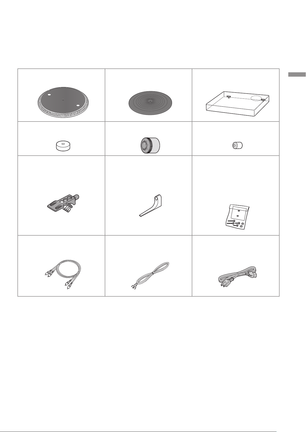
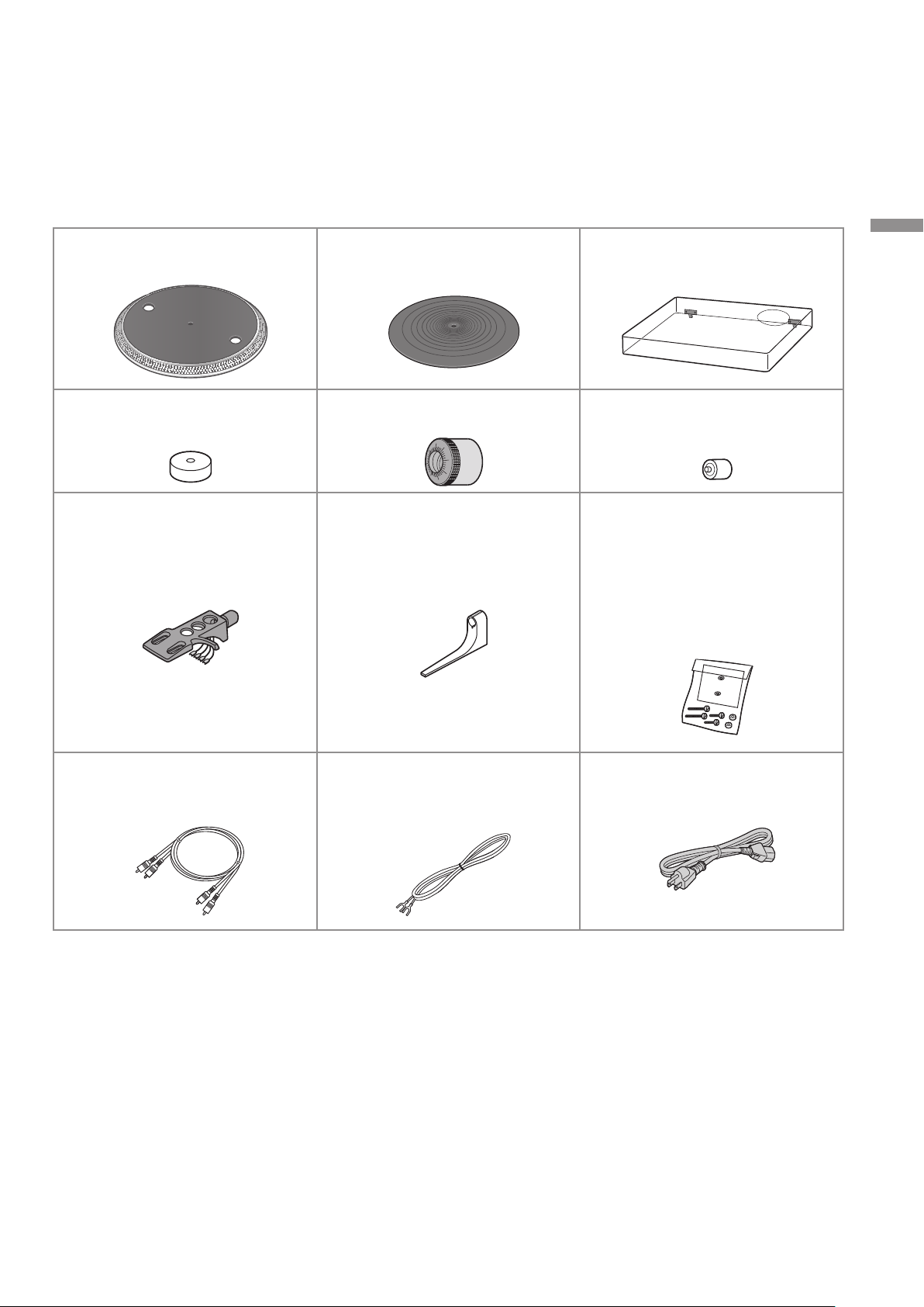
Accessories
In order to prevent damage during shipping some of the equipment has been disassembled.
Please check and identify the supplied accessories.
Turntable (1 pc.)
(TTV0027A)
EP record adaptor (1 pc.)
(TEKX077)
Head shell (1 pc.)
(TPBGA003)
Turntable mat (1 pc.)
(RGS0008)
Balance weight (1 pc.)
(TYL0056)
Overhang gauge (1 pc.)
(RMR2210-W)
Dust cover (1 pc.)
(TTPA0683)
Auxiliary weight (1 pc.)
(TKKH51441)
Screw set for cartridge (1 set)
(TTV0022)
Nuts (2 pc.)
Screws-short (2 pc.)
Screws-long (2 pc.)
Washers (2 pc.)
(Supplied in a bag)
Before use
PHONO cable (1pc.)
(K2KYYYY00257)
The model numbers of the accessories are as of February 2017.
They are subject to change without notice.
Keep the packaging materials after taking out the goods.
You will need them when carrying the product for a long distance.
Follow the local regulations when disposing of the product.
Do not use any other AC power supply cord, PHONO cable and PHONO earth lead except the
supplied one.
Keep the cartridge, auxiliary weight, nuts, screws and washers out of reach of children to prevent
swallowing.
PHONO earth lead (1pc.)
(K4EY1YY00160)
AC power supply cord (1 pc.)
(K2CG3YY00191)
(09)
09
English
Page 10
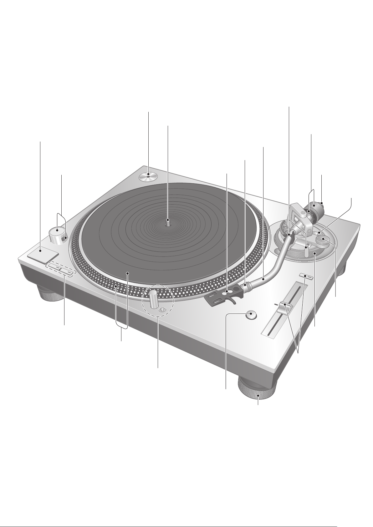
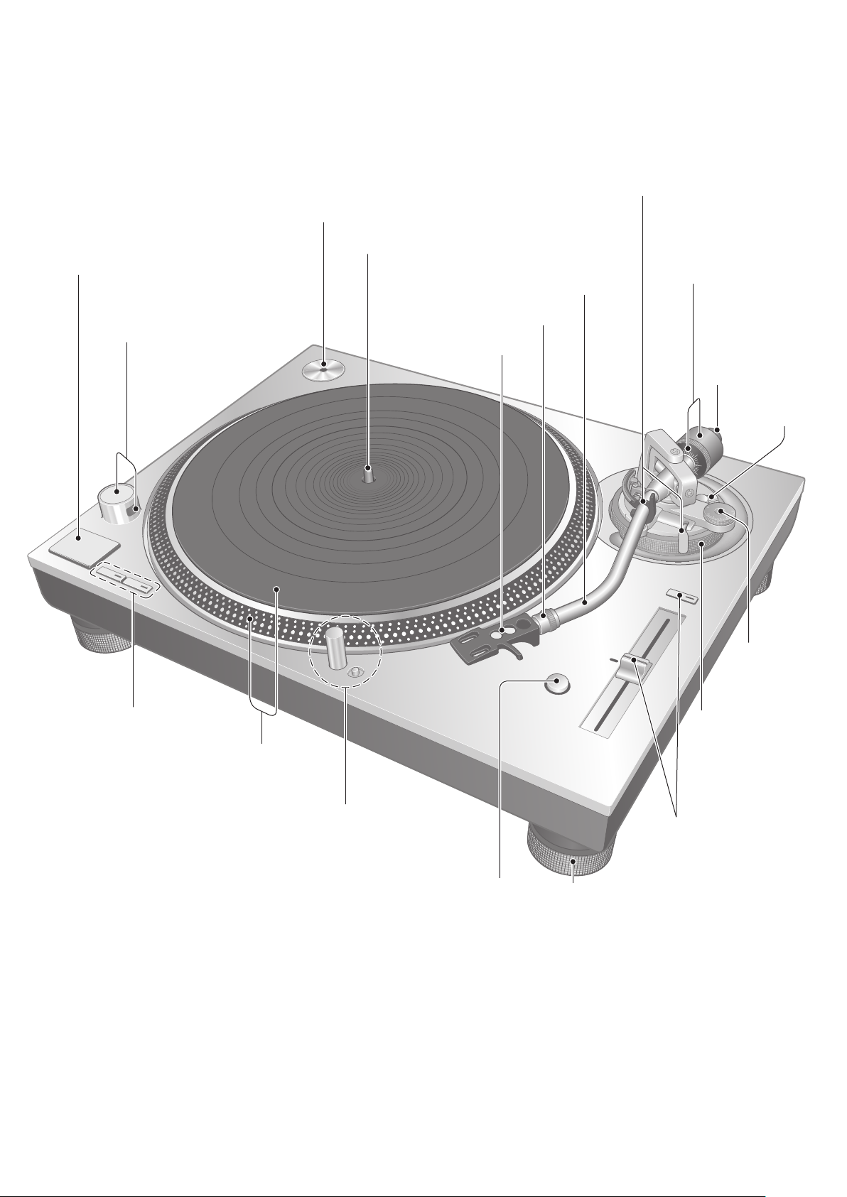
Parts Name
Numbers such as ( 20) indicate reference pages.
EP record adaptor ( 22)
Center spindle (
START-STOP button (
ON/OFF (power) ( 22)
Strobe light ( 24)
22)
14)
Tone arm (
Locking nut (
Head shell ( 13)
Arm clamp ( 18)
Arm rest ( 18)
Cue lever ( 18)
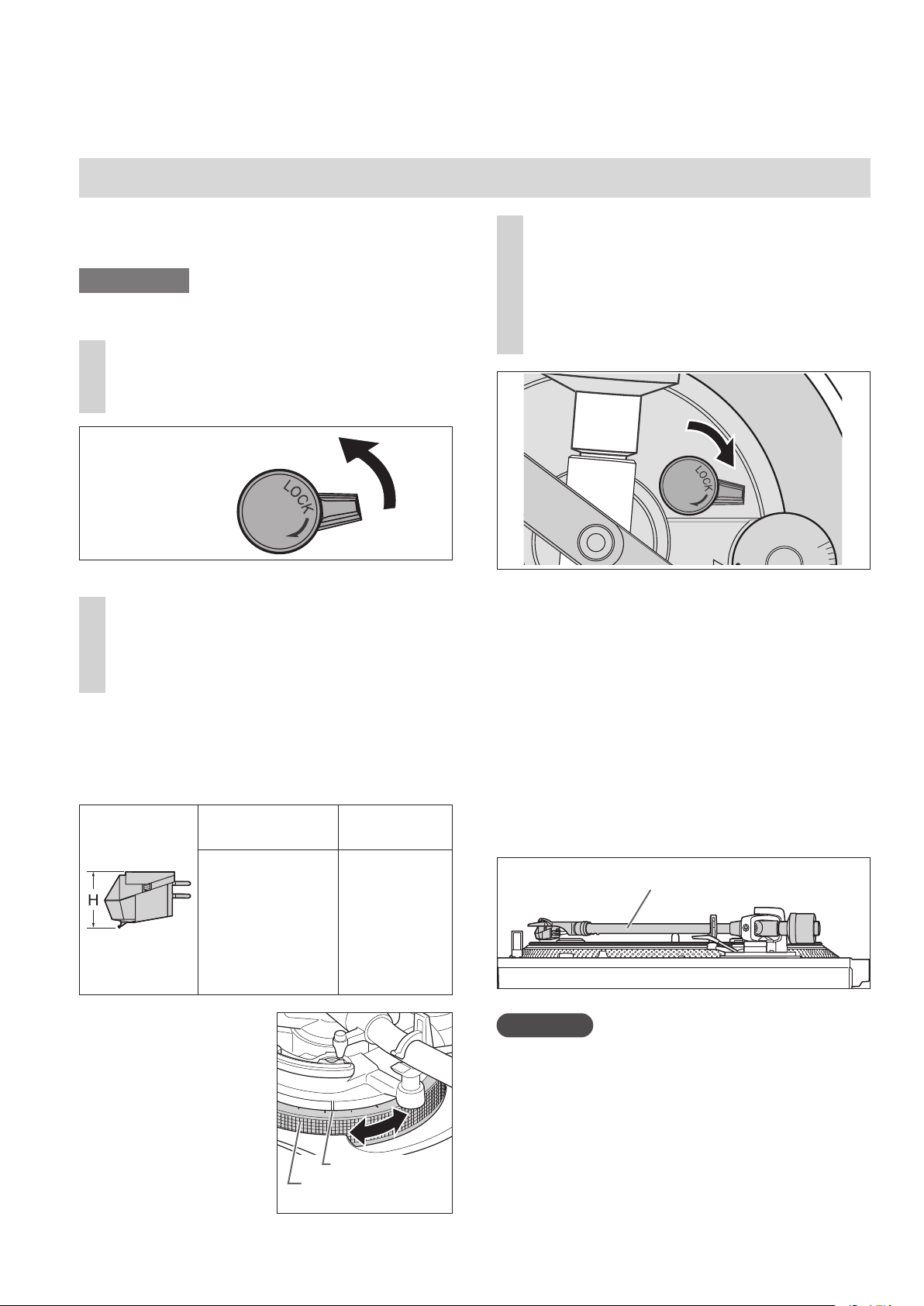
15)
15)
Balance weight
Stylus pressure
control (
Auxiliary
weight
mounting
location (
18)
(
Arm lock
15)
15)
( 20)
Speed select buttons ( 22)
Turntable ( 14)
Turntable mat ( 14)
Stylus light switch ( 23)
Stylus light ( 23)
RESET button ( 23)
Pitch range select
button ( 24)
PITCH ADJ control
( 24)
Insulator ( 17)
Anti-
skating
control
( 19)
Arm-height
control ring
( 20)
(10)
10
English
Page 11
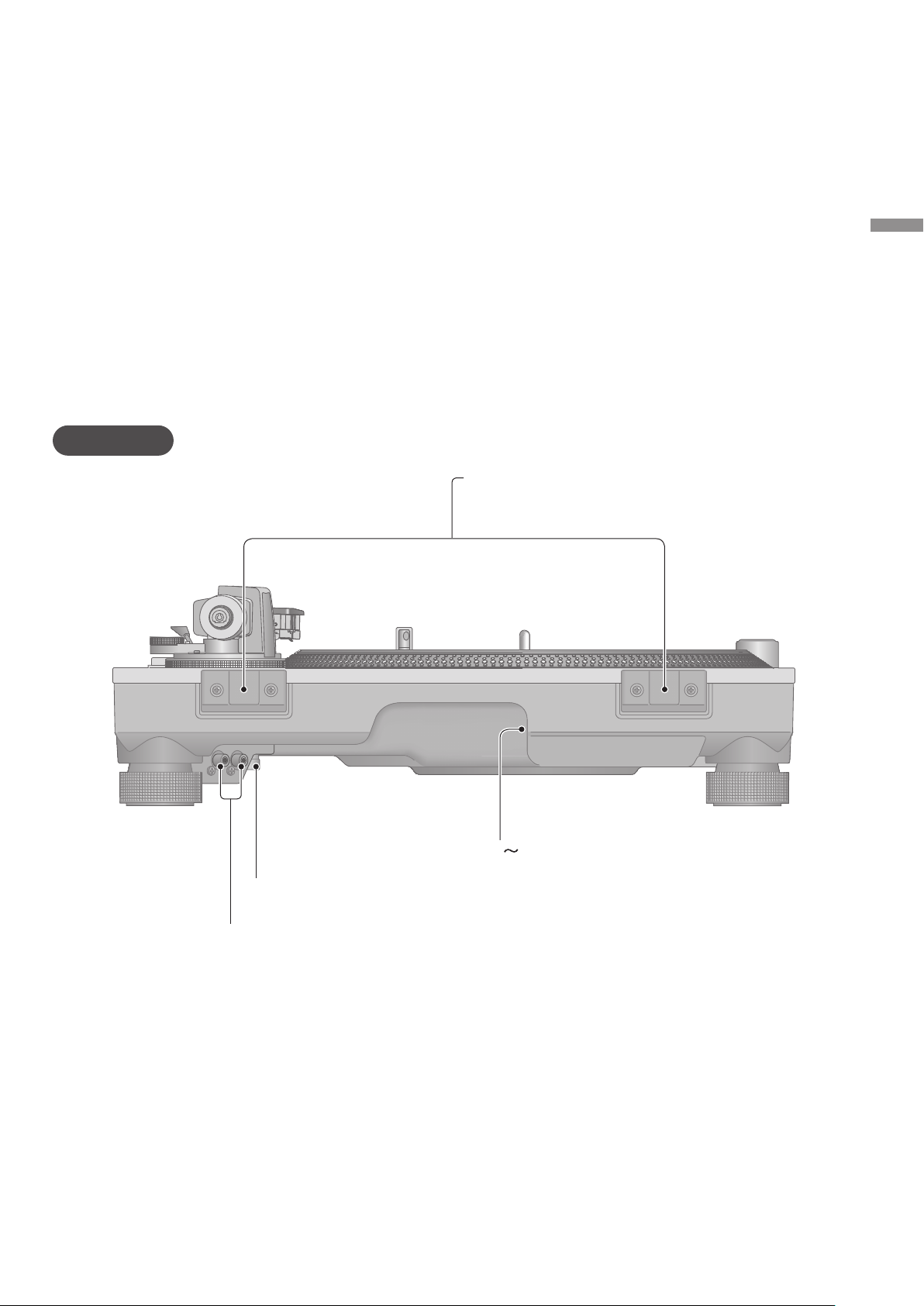
Back
Before use
Dust cover fitting part ( 17)
PHONO earth terminal ( 16)
PHONO output terminal ( 16)
AC (
) input terminal ( 16)
(11)
11
English
Page 12
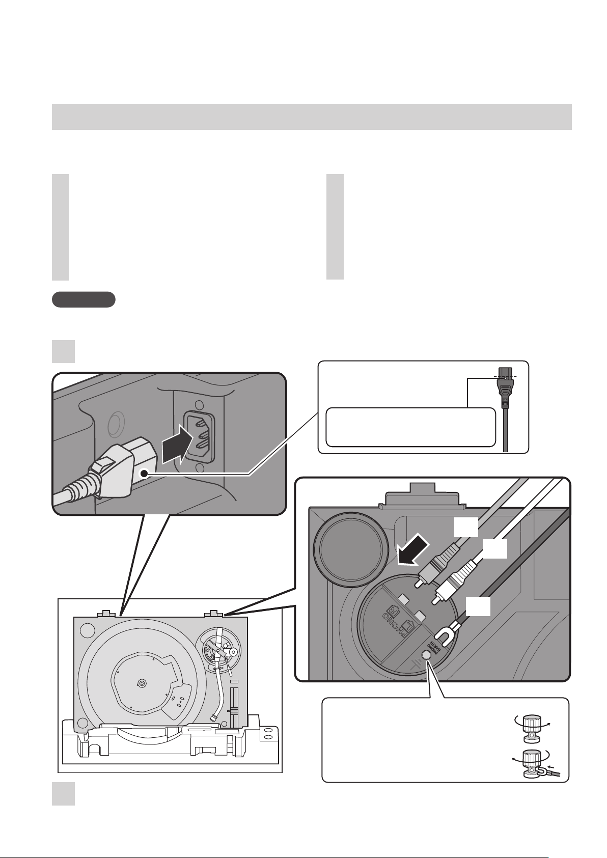
Putting the player together
Connecting to the PHONO terminals and AC IN terminal
Make connection to the PHONO terminals and AC IN terminal before setting up or installing
the player.
Take out the player from the
1
package, attach the “FRONT
styrofoam” and place the player
with its front side down so that
you can make connection to the
PHONO terminals and AC IN
terminal on the back side.
Attention
Be careful not to tip over the player.
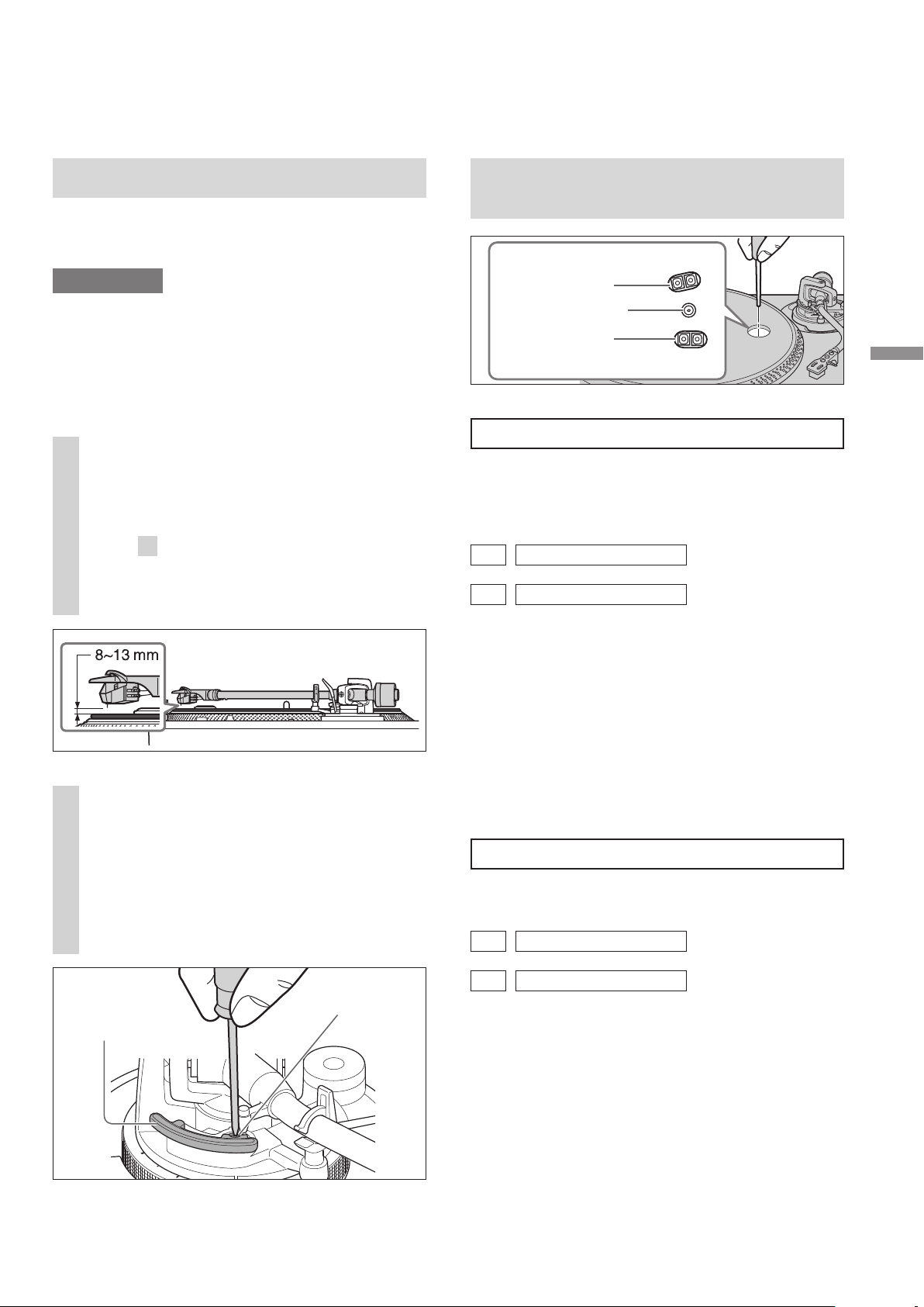
Connect the PHONO cable, PHONO earth
2
lead and AC power supply cord.
Connect the supplied PHONO
2
cable, PHONO earth lead, and
AC power supply cord.
Insert the AC power supply cord
up to a point just before the
round hole.
Attach the “FRONT styrofoam” and
1
place the player with its front side down.
(12)
12
English
(Red)
(White)
(Black)
Connecting the PHONO earth lead to
the player and amplifier.
Turn the terminal to the left to loosen.
Insert the earth lug and tighten the
k
terminal securely.
Page 13
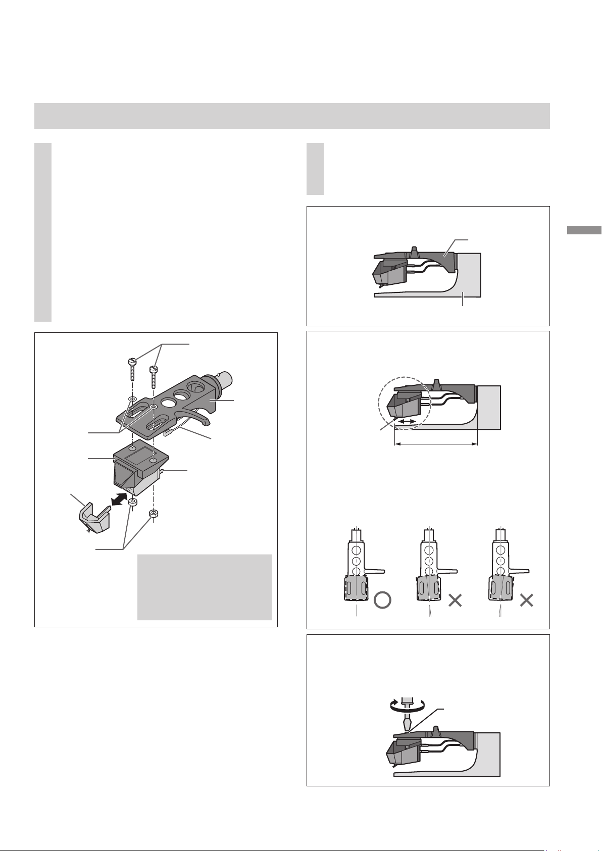
Attaching the cartridge
Attach a cartridge (store-bought)
1
tentatively.
Follow the cartridge’s instructions to
correctly attach it to the head shell, and
tighten the screws lightly.
zIf the mounting screws are included in
the cartridge, use them.
zWhen playing SP records, use a cartridge
for SP records.
zUse a commercially available mini flat
screwdriver (4 mm
zBe careful not to touch the stylus tip.
(Example)
Washers
[5/32”]).
Screw for
cartridge
Lead wire
Head
shell
Adjust the overhang.
2
Use the included overhang gauge.
Fit the overhang gauge to the head shell.
Head shell
Overhang gauge
k
Move the cartridge to line the stylus tip up
with the end of the gauge.
Stylus tip
52 mm
Getting started
Cartridge
Stylus
Nuts
Terminal
(Lead wire) (Terminal)
Red
Green
White
Blue
R+ (Red)
R- (Green)
L+ (White)
L- (Blue)
z The cartridge should be parallel on
the shell head when viewed from the
top and side (the illustration is the top
view).
Tighten the screw for cartridge.
l
z Be careful not to allow the cartridge to
slip out of place.
Screw for cartridge
The overhang can be adjusted optimally.
English
(13)
13
Page 14
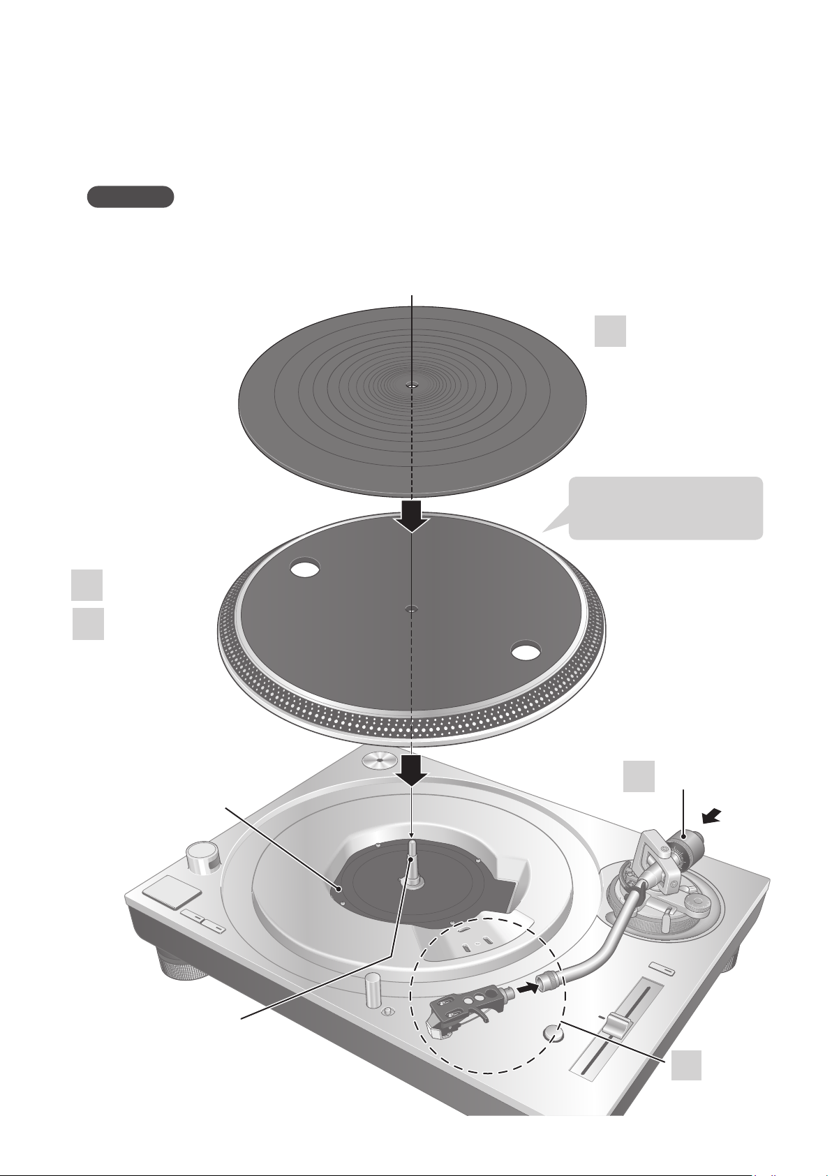
Putting the player together
In order to prevent damage during shipping, some of the equipment has been disassembled.
Put the player together in the following order.
Attention
zDo not connect the AC mains lead until set up is complete.
zWhen fitting the turntable, prevent foreign material from getting in between the main unit and
turntable.
zDo not touch or scratch the board.
(continued)
3
Handle carefully as
this is heavy.
Turntable mat
1
2
Turntable
Board
Balance weight
5
(14)
14
English
Centre spindle
4
Head shell
Page 15

Before fitting the turntable
Fitting the turntable mat
Remove the magnet cover from
1
the turntable.
zThere is a magnet and its cover on the
back side of the turntable.
Remove the magnet cover before fitting
to the main unit.
Back side of the turntable
Magnet cover
Magnet
Attention
zKeep any magnetic-sensitive object such as
a magnetic card and watch away from the
magnet.
zPrevent the turntable from hitting the main
unit or falling off.
Prevent dust or iron powder from adhering
to the magnet on the back side.
zDo not touch the fixing screws (three
locations) of the turntable. The rating
performance cannot be guaranteed if they
are out of position.
Fixing
screw
Lay the turntable mat on the
3
turntable.
Attaching the head shell
Fit the head shell with the
4
cartridge into the tone arm.
Keep the head shell horizontal
and tighten the locking nut.
zBe careful not to touch the stylus tip.
Locking nut
Head shell
Attaching the balance weight
Attach the balance weight to the
5
rear of the tone arm.
Getting started
Fitting the turntable
Slowly set the turntable on the
2
center spindle.
To remove the turntable
As shown in the
figure on the right,
set your fingers in
the two holes on
the turntable, hold
the center spindle
down and remove
the turntable
upward.
Attention
zBe careful when handling the turntable, as it
is heavy.
zKeep your fingers from being caught.
zWipe off fingerprints or dirt with a soft cloth.
Balance weight
Auxiliary weight
zAttach the included auxiliary weight to the
rear of the tone arm according to the weight
of your cartridge.
For adjustable cartridge weight ranges, see
"Applicable cartridge weight range". (27)
Note
zThe inside of the balance weight is greased.
(15)
English
15
Page 16
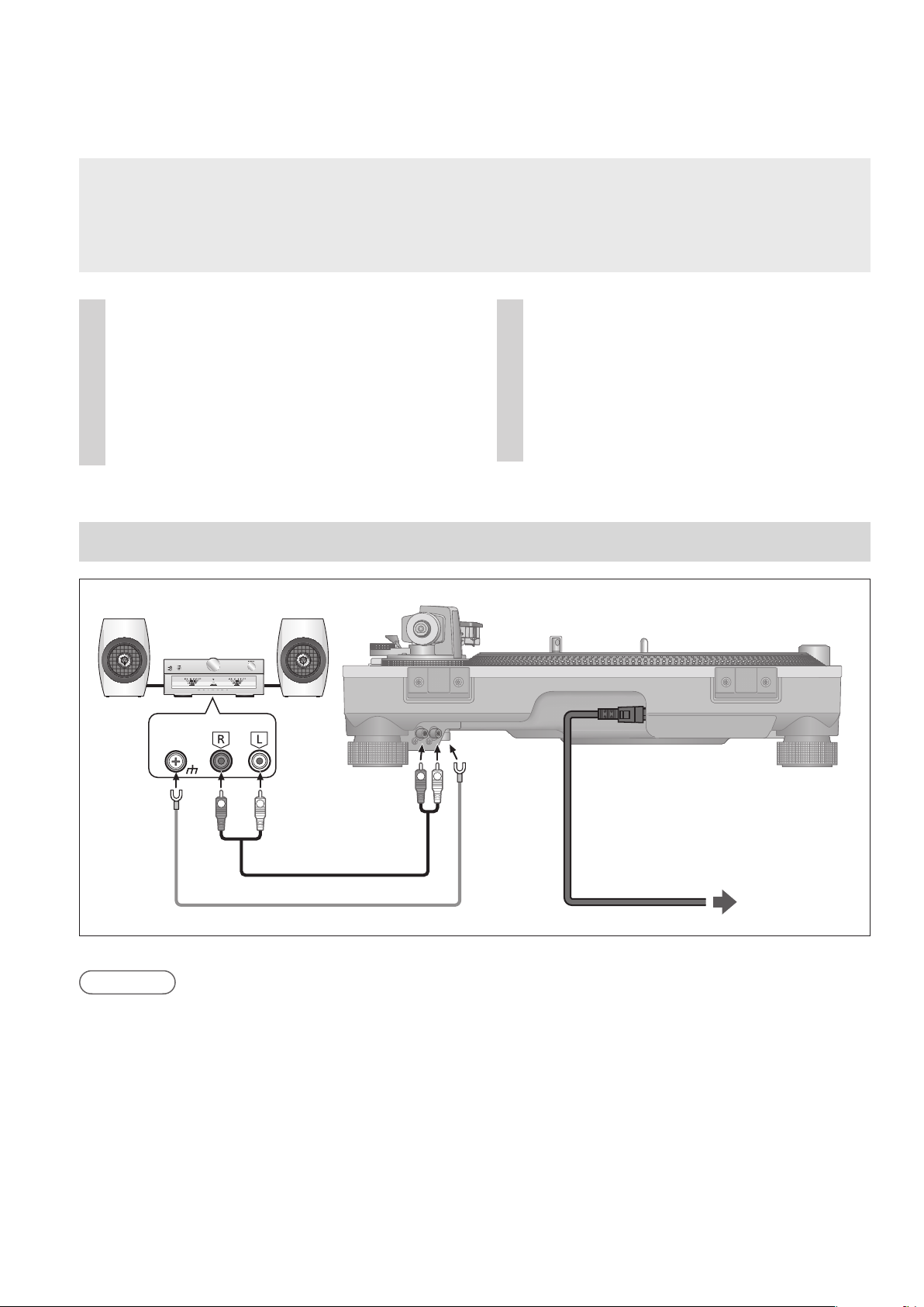
Connections and installation
zTurn off all units and disconnect the AC power supply cord from the outlet before making any
connections.
zConnect the AC power supply cord only after all other connections are completed.
zBe sure to connect the PHONO earth lead. Otherwise mains hum may occur.
zRefer also to the instruction manual of the connected device.
Connect the PHONO cable and
1
PHONO earth lead to the PHONO
input terminals of the connected
equipment.
zYou will not have adequate volume or
sound quality if the connected amplifier
has no PHONO input terminals.
Connect the AC power supply
2
cord.
zConfirm the wattage of the AC outlet on
the connected equipment before using it
for this unit.
(This unit consumes 11 W.)
Connecting to an integrated amplifier or component system
Amplifier(not included)
EARTH
PHONOPHONO
Back of main unit
LR
LR
PHONOcable
PHONO earth lead
Note
zAlthough the AC power switch is in the "OFF" position, the unit is not completely disconnected
from the mains. Remove the plug from the main electrical outlet if you will not be using the unit for
an extended period of time. Place the unit so the plug can be easily removed.
AC power
supply cord
To a household
mains socket
(16)
16
English
Page 17
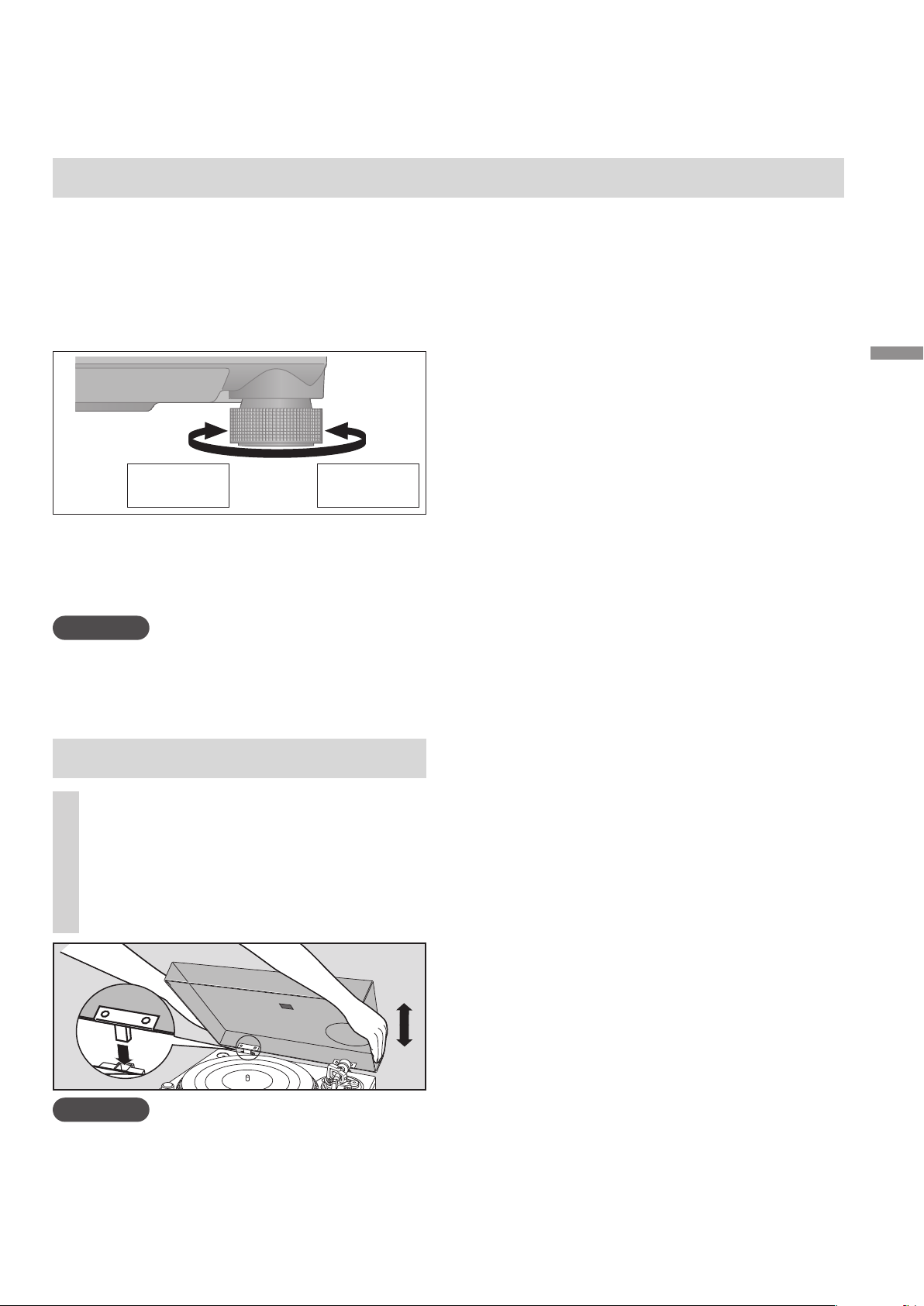
Installation
Install the unit on a horizontal surface
protected from vibrations.
Keep this unit as far as possible from speakers.
Adjusting the height to make the
unit horizontal
Increases
the height
Raise the main unit to turn the insulators and
adjust the height.
Clockwise: Reduces the height.
z
Anti-clockwise: Increases the height.
z
Attention
zDo not turn the insulators too far.
Doing so may cause them to come off or
damage them.
Reduces
the height
Fit the dust cover
Hold the dust cover with both
1
hands and insert it into the dust
cover fitting parts ( 11) on the
player.
zTo remove the dust cover, keep it open
and lift it straight above.
Notes for installation
zBefore you move the unit, remove all devices
connected and turn off the power supply.
zEnsure the unit is not exposed to direct
sunlight, dust, humidity, and heat from a
heating appliance.
zThis unit may pick up interference from a
radio if there is one nearby.
Keep the unit as far as possible from a radio.
zDo not install the unit on a heat source.
zAvoid a place with large temperature variations.
zAvoid a place with frequent condensation.
zAvoid an unstable place.
zDo not put an object on the unit.
zDo not install the unit in a confined space
such as a book shelf.
zInstall the unit at a position well away from
walls or other devices to ensure effective
heat radiation from the inside of the unit.
zMake sure that the material of the
installation location is sufficiently strong to
withstand the weight of this unit.
zNote that the unit may be damaged by
cigarette smoke or moisture from an
ultrasonic humidifier.
Condensation
Think of taking out a cold bottle from a
refrigerator. If you leave it in a room for a while,
dewdrops will form on the bottle surface.
This phenomenon is called “condensation“.
zConditions causing condensation
Rapid temperature change (caused by
moving from a warm place to a cold place or
vice versa, rapid cooling or heating, or direct
exposure to cooled air)
High humidity in a room with much steam,
etc.
Rainy season
zCondensation may damage the unit. If it
has occurred, turn the unit off and leave it
until it adapts to the ambient temperature
(approximately 2 to 3 hours).
Getting started
Attention
Return the tone arm to the arm rest and fix
z
it with the arm clamp before you attach or
detach the dust cover.
zWhen inserting the dust cover, prevent the tip
of the hinges from hitting and damaging the
main unit.
(17)
17
English
Page 18
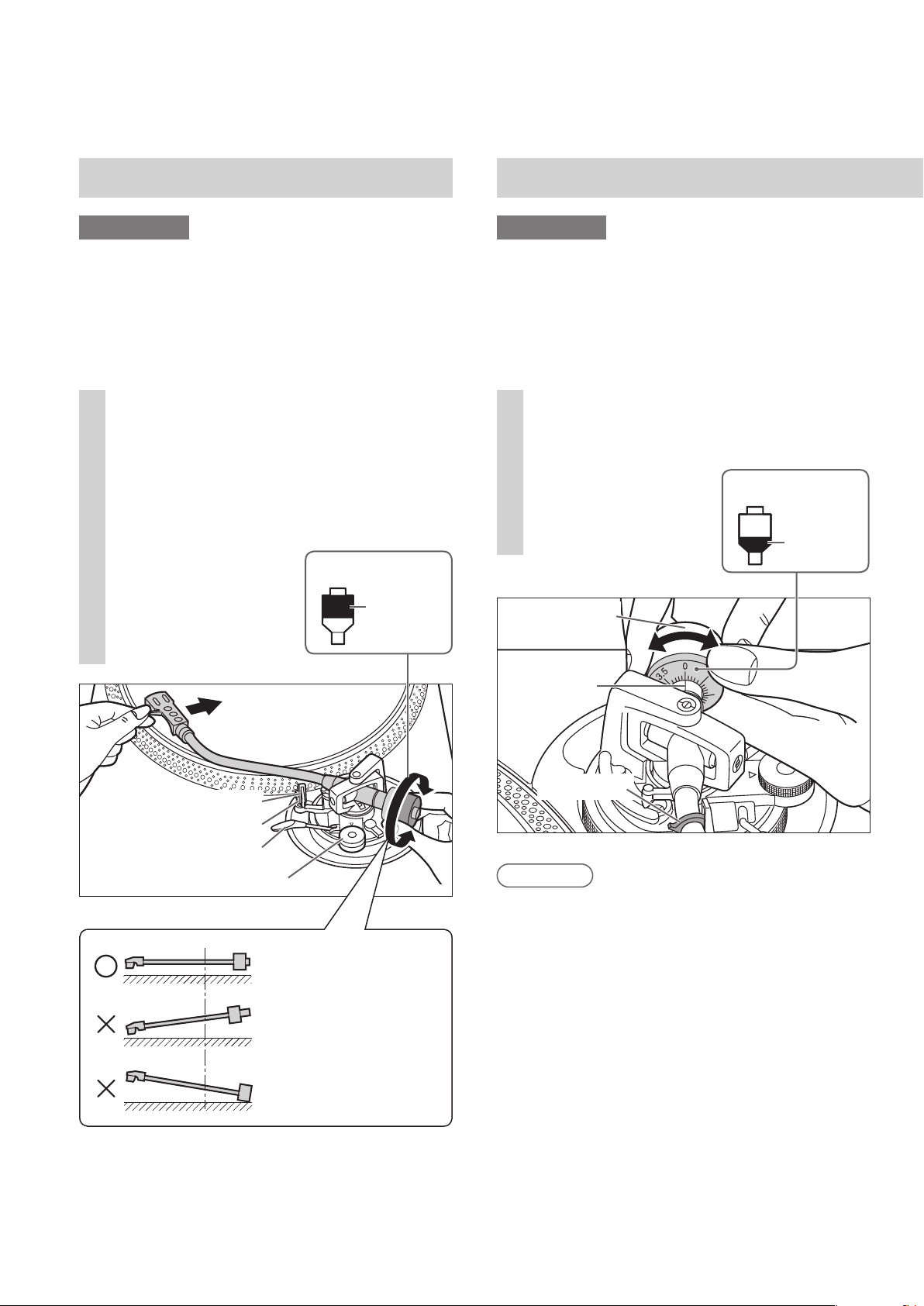
Adjustment
Horizontal balance Stylus pressure
Preparation
zFirst, remove the dust cover.
zRemove the stylus cover, taking care not
to damage the stylus, then release the arm
clamp.
zLower the cue lever.
zTurn the anti-skating control to “0”.
Free the tone arm from the arm
1
rest and adjust horizontal balance
by turning the balance weight.
Hold the tone arm and turn the balance
weight in the arrow direction to adjust
the balance until the arm is approximately
horizontal.
zTake care not to
allow the stylus tip
to touch the
turntable or main
unit.
Balance weight
Hold here
to turn
Preparation
zFirst, remove the dust cover.
zReturn the tone arm to the arm rest and fix it
with the arm clamp.
Turn the stylus pressure control
1
until “0“ comes to the center line
of the rear of the tone arm.
zHold the balance
weight still while
doing this.
Balance weight
Stylus pressure
control
Hold here
to turn
Arm clamp
Arm rest
Cue lever
Anti-skating control
Balanced and the tone
arm is parallel to the
turntable.
The balance weight is
too far forward.
The balance weight is
too far back.
Center line
Arm clamp
Note
zRefer to the user's guide for your stylus for
the appropriate stylus pressure.
(18)
18
English
Page 19

Anti-skating
Turn the balance weight to adjust
2
to the appropriate stylus pressure
for the cartridge.
zThe stylus pressure control will turn
together with the balance weight.
zTurn until the center line points to the
appropriate stylus pressure.
Balance weight
Hold here
to turn
Turns
together
Center line
Turn the anti-skating control to
1
adjust it to the same value as the
stylus pressure control.
0
1
3
2
Getting started
Note
zFor stylus pressures 3 g and above, adjust
anti-skating control to “3”.
(19)
19
English
Page 20
Adjustment
0
(continued)
Tone arm height
Make this adjustment only if the cartridge you
are using makes it necessary.
Preparation
zPut a record on the turntable.
Release the arm lock.
1
Arm lock
Adjust the height with the arm-
2
(Released)
(Locked)
height control ring.
Adjust the arm height until the tone arm
becomes parallel to the record.
Use the chart below as reference to find the
appropriate position mark for the height of
your cartridge.
(For supplied head shell)
Cartridge height
(H) in millimeters
17
18
19
20
21
22
23
Height control
position
0
1
2
3
4
5
6
After arm height adjustment is
3
finished, lock the tone arm by
turning the arm lock knob.
zBe sure to turn the arm lock knob to the
end as shown in the figure below. You
may need to apply some force to do so.
A
T
K
I
N
S
-
G
I
T
N
A
When you don't know the cartridge
3
height (H) or when you don’t use
the supplied head shell
Remove the stylus cover, taking care not to
damage the stylus, then release the arm clamp.
Lower the cue lever, rest the stylus on the
record and adjust the height control until the
tone arm and record are parallel.
zIf the cartridge height (H) is too small to
make them parallel to each other, add a
“cartridge spacer” (not supplied).
Parallel to a record
k
Turn the arm-height
control ring to align
the position mark
with the index line.
0 to 6 mm are
marked on the arm
height control ring.
(20)
20
English
Attention
zBe careful not to damage the stylus tip.
zDo not use the product with the arm lock
3
Arm-height control
ring
4
Index line
released.
zFor finer adjustment, use a level (not included)
to adjust the arm height so that the cartridge
becomes parallel to a record.
Page 21
Armlift height
Make an adjustment according to your
cartridge if necessary.
Preparation
Put a record on the turntable.
Remove the stylus cover, taking care not
to damage the stylus, then release the arm
clamp.
Lift the cue lever and move the tone arm over
the record.
Check the armlift height (distance
1
between the stylus tip and record
surface).
If adjustment is needed, go to
step
The armlift height is factory-adjusted to
8 to 13 mm
Return the tone arm to the arm
2
rest and fix it with the arm clamp.
Turn the adjustment screw.
Turning the screw clockwise lowers the
armlift.
Turning the screw anti-clockwise raises
the armlift.
Armlift
.
2
(5/16” to 33/64”)
1
.
Armlift
screw
Adjusting the turntable startup/
brake speed
BRAKE button
S (Slow)
F (Fast)
Confirmation lamp
Torque button
L (Low)
H (High)
Press the center of the button lightly.
Startup speed
You can select from three options of the startup
speed (the time to reach the constant speed) after
[START-STOP] is pressed and the torque gain at the
constant speed.
(Factory setting: 3)
[3] Fast startup
〜
[1] Slow startup
The confirmation lamp blinks the specified number
of times according to the current setting when you
press the H or L torque button.
To change the setting, press the H or L torque
button while the lamp is lit.
Example: If the current setting is [3] and you
press the L button twice, the setting will
change to [1].
After you press the torque button, the
confirmation lamp blinks the specified number of
times showing the new setting, stays lit for two
seconds and then goes off.
Brake speed
You can select from five options of the brake speed
to stop the turntable after [START-STOP] is pressed.
(Factory setting: 5)
[5] Stops fast
〜
[1] Stops slowly
The confirmation lamp blinks the specified number
of times according to the current setting when you
press the F or S brake button.
To change the setting, press the F or S brake
button while the lamp is lit.
Example: If the current setting is [5] and you
press the S button twice, the setting will
change to [3].
After you press the brake button, the confirmation
lamp blinks the specified number of times showing
the new setting, stays lit for two seconds and then
goes off.
BRAKE
S
L
TORQUE
F
H
Getting started
(21)
21
English
Page 22

Playing records
・
Preparation
1 Put a record (not included) on the turntable.
2 Take off the stylus cover and release the arm clamp.
Turn [ON/OFF] to turn the unit on.
1
The strobe light comes on. 33-1/3 rpm is
automatically selected and the indicator [33]
lights.
78
33 45
+6.4
・
3.3
・
0
%
-
3.3
Strobe light
Attention
Do not press [START-STOP] when the turntable is removed.
If you have accidentally pressed [START-STOP].
zThe indicator of the speed select button ([33] or [45]) starts blinking.
If it is blinking, turn [ON/OFF] to turn the unit off, fit the turntable and then turn [ON/OFF] to turn
the unit on.
Indicator
Press [START-STOP].
2
The turntable starts revolving.
START・STOP
33
EP record adaptor
1
2
Speed select buttons
Indicators
Center spindle
2
1
2
4
·
5
3
(22)
22
English
Page 23

Press [RESET] to light the pitch
PITCH ADJ
RESET
3
control blue LED lamp.
The unit plays at a preset pitch (33-1/3, 45
or 78 rpm) regardless of the [PITCH ADJ]
position.
zFine adjustment to
Blue LED
indicator
RESET
button
pitch ( 24)
When play finishes
Lift the cue lever, return the tone arm to the
arm rest and lower the cue lever.
Press [START-STOP].
k
The electronic brake gently stops the
turntable.
Turn [ON/OFF] to turn the unit off.
l
Clamp the tone arm with the arm clamp.
Put the stylus cover back on (to protect the
stylus tip).
To light up the stylus
The stylus tip is illuminated during play.
Stylus light
Lift the cue lever and move the
4
tone arm over the record.
Cue lever
Lower the cue lever slowly.
5
The tone arm moves down slowly.
Play starts.
Stylus light switch
Press the stylus light switch.
zThe stylus light (white LED) rises up and
illuminates the stylus.
zPress down the stylus light to turn off the
light.
Attention
Press the stylus light switch firmly. If the switch
is lightly pressed, the light may come on but not
rise up.
When playing EP records
zPress the speed select button [45] ([45]
lights).
zFit the EP record adaptor over the center
spindle.
When playing SP records
zPress the speed select buttons [33] and [45]
at the same time (78 rpm: [33] and [45]
light).
Playing
back
To temporarily stop play
Lift the cue lever.
zThe stylus lifts off the record.
zTo start play again, lower the cue lever.
When using a record stabilizer (not
included)
zSee the instruction manual of the record
stabilizer.
zMaximum weight: 1 k
g
English
(23)
23
Page 24

Pitch control
PITCH ADJ
RESET
×
2
(fine adjustment to pitch)
Press [RESET] to turn off the blue
1
LED light.
Press the pitch range select
2
button to select the pitch range.
z[×2] light on: ±16 %
z[×2] light off: ±8 %
3
While the turntable is revolving
Slide [PITCH ADJ].
zPitch can be adjusted between approx.
–8 % and +8 % or approx. –16 % and
+16 % according to your selection.
zThe numbers represent approximate
percentages for your adjustment.
To measure pitch
The four rows of strobe mirrors around
the edge of the turntable can assist you in
measuring pitch.
Strobe
mirrors
+6.4 % change in pitch when stationary
+3.3 % change in pitch when stationary
Normal turntable speed (33-1/3, 45 or 78
r/min) when stationary
-3.3 % change in pitch when stationary
Attention
The strobe mirrors are lit by the strobe light
(blue LED) synchronizing with the precise
frequency of digital control.
Always use the blue LED to measure the pitch.
Pitch range select
button
Blue LED indicator
Pitch control
RESET button
To reset pitch to the preset value
Press [RESET].
The blue LED indicator lights and the pitch
immediately returns to a preset value regardless
of the [PITCH ADJ] position.
(33-1/3, 45 or 78 rpm)
zBlue LED on: Fixed to the preset value.
zBlue LED off: Can be adjusted with
[PITCH ADJ].
+6.4
・
3.3
・
0
-
3.3
・
Strobe light
%
(24)
24
English
Page 25

Maintenance
Care of the parts
Thoroughly clean dust off the stylus and
record.
zTake off the head shell with the cartridge and
clean the stylus using a soft brush.
Brush from the base to the tip.
zUse a record cleaner to keep your records
clean.
Head shell
terminals
Moving the unit
Repackage the unit in the packaging it came
in.
Keep the packaging materials after taking out
the goods.
If you no longer have the packaging, do the
following:
zTake off the turntable and turntable mat and
carefully wrap them.
zRemove the head shell and balance weight
from the tone arm and carefully wrap them.
zClamp the tone arm with the arm clamp and
tape it in place.
zCarefully wrap the main unit in a blanket or
paper.
Wipe the head shell terminals occasionally.
Wipe the head shell terminals with a soft cloth
and fit the head shell to the tone arm.
Turn the amplifier volume down or turn the
amplifier off before fitting or removing the
head shell.
Damage to your speakers can occur if the head
shell is moved while the volume is turned up.
Cleaning the dust cover and
cabinet
Wipe the dust cover and cabinet with a soft
cloth.
Do not touch the board while cleaning.
Otherwise, the player may fail.
When dirt is heavy, wring a wet cloth tightly to
wipe the dirt, and then wipe it with a soft cloth.
zDo not use solvents including benzene,
thinner, alcohol, kitchen detergent, a
chemical wiper, etc. This might cause the
exterior case to be deformed or the coating
to come off.
zDo not wipe the dust cover while playing a
record.
This can cause static electricity. This static can
cause the tone arm to be attracted towards
the dust cover.
Repackaging
Before repackaging,
remove the balance
weight and insert the
0
1
3
2
WEEE symbol
Disposal of the product outside the EU
countries
This symbol is valid within the EU
only.
Contact a local governmental office
or your dealer to confirm a right
manner of disposal.
tone arm support
under the tone arm.
Playing
back
Maintenance
(25)
25
English
Page 26

Troubleshooting guide
Before requesting service, make the below checks. If you are in doubt about some of the check
points, or if the remedies indicated in the chart do not solve the problem, contact your dealer.
No power.
zIs the AC power supply cord plugged in?
¨
Plug the mains lead in firmly. ( 16)
There is power but no sound.
Sound is weak.
zAre connections to the amplifier/receiver’s PHONO terminals correct?
¨
Connect the PHONO cables to the amplifier’s PHONO input terminals. ( 16)
Left and right sounds are reversed.
zAre the stereo connection cable connections to the amplifier or receiver reversed?
¨
Double check all connections. ( 16)
zAre connections of the head shell's lead wires to the cartridge terminals correct?
¨
Double check all connections. ( 13)
Humming is heard during play.
zAre there other appliances or their AC power supply cord near the stereo connection cable?
¨
Separate the appliances and their AC power supply cord from this unit.
zIs the earth lead connected?
¨
Make sure the earth lead is correctly connected. ( 16)
The Strobe light or the blue indicator blinks.
Perform the following operation when the strobe light or the blue indicator blinks.
The symptom may be improved.
Turn [ON/OFF] to OFF.
k
Pull out the power plug, wait for three seconds, and then insert the plug again.
Turn [ON/OFF] to ON and press
l
[START-STOP] to rotate the turntable.
zIf the strobe light or the blue indicator blinks again, check which one is blinking and contact our
service representative.
(26)
26
English
Page 27

Specifications
General
Power supply AC 120V, 60 Hz
Power
consumption
Dimensions
(W×H×D)
Mass Approx. 11.5 k
Operating
temperature
range
Operating
humidity range
Turntable section
Type Direct drive manual
Drive method Direct drive
Motor Brushless DC motor
Turntable Aluminum diecast
Turntable speeds 33-1/3, 45 and 78 rpm
Variable range
pitch
11 W (Power ON)
0.2 W (Power OFF)
453 x 173 x 372 mm
(17-27/32“ × 6-13/16“ ×
14-21/32“)
g
(25.4 lbs
0 °C to +40 °C
(+32 °F to +104 °F
35 % to 80 % RH
(no condensation)
turntable
Diameter: 332 mm
(13-5/64“)
Mass: Approx. 2.5 kg
(5.51 lbs
(including a rubber sheet)
±8 % and ±16 %
)
)
)
Tone arm section
Type Static Balance
Effective length 230 mm (9-1/16“)
Overhang 15 mm (19/32“)
Tracking error
angle
Offset angle 22°
Arm-height
adjustment range
Stylus pressure
adjustment range
Head shell weight Approx. 7.6
Applicable
cartridge weight
range
Head shell
terminal lug
Specifications are subject to change without
notice.
Within 2° 32' (at the outer
groove of 30 cm (12“)
record)
Within 0° 32' (at the inner
groove of 30 cm (12“)
record)
0 – 6 mm (0“ - 15/64“)
0 – 4 g (direct reading)
g
(Without the auxiliary weight)
5.6 to 12.0
14.3 to 20.7 g (including the
head shell)
(With the auxiliary weight)
10.0 to 16.4
18.7 to 25.1 g (including the
head shell)
1.2 mm φ 4-pin terminal lug
g
g
Starting torque 2.2 kg-cm (1.91 lb-in)
Build-up
characteristics
Braking system Electronic brake
Wow and flutter 0.025 % W.R.M.S.
Rumble 78 dB (IEC 98A weighted)
0.7 s. from standstill to
33-1/3 rpm
(JIS C5521)
(27)
27
English
Maintenance
Page 28

Others
Limited Warranty (ONLY FOR U.S.A.)
Limited Warranty (ONLY FOR U.S.A.)
Others
Limited Warranty (ONLY FOR U.S.A.)
Technics Products – Limited Warranty
Limited Warranty Coverage
(For USA Only)
If your product does not work properly because of a defect in materials
THERE ARE NO EXPRESS WARRANTIES EXCEPT AS LISTED
UNDER “LIMITED WARRANTY COVERAGE”.
THE WARRANTOR IS NOT LIABLE FOR INCIDENTAL OR
CONSEQUENTIAL DAMAGES RESULTING FROM THE USE OF
THIS PRODUCT, OR ARISING OUT OF ANY BREACH OF THIS
WARRANTY.
(As examples, this excludes damages for lost time, travel to and
from the servicer, loss of or damage to media or images, data or
other memory or recorded content. The items listed are not
exclusive, but for illustration only.)
ALL EXPRESS AND IMPLIED WARRANTIES, INCLUDING THE
WARRANTY OF MERCHANTABILITY, ARE LIMITED TO THE
PERIOD OF THE LIMITED WARRANTY.
Some states do not allow the exclusion or limitation of incidental
or consequential damages, or limitations on how long an implied
warranty lasts, so the exclusions may not apply to you.
This warranty gives you specific legal rights and you may also have
other rights which vary from state to state. If a problem with this
product develops during or after the warranty period, you may
contact your dealer or Service Center. If the problem is not handled
to your satisfaction, then write to:
Consumer Affairs Department
Panasonic Corporation of North America
661 Independence Pkwy
Chesapeake, VA 23320
PARTS AND SERVICE, WHICH ARE NOT COVERED BY THIS
LIMITED WARRANTY, ARE YOUR RESPONSIBILITY.
As of December 2015
for all your Technics gear
Go to
http://shop.panasonic.com/support
Get everything you need to get the most out of
your Technics products
Accessories & Parts for your Camera, Phone, A/V
products, TV, Computers & Networking, Personal
Care, Home Appliances, Headphones, Batteries,
Backup Chargers & more…
Customer Services Directory
For Product Information, Operating Assistance,
Parts, Owner’s Manuals, Dealer and Ser vice info
go to http://shop.panasonic.com/support
For the hearing or speech impaired T TY: 1- 877-833-8855
Others
Limited Warranty (ONLY FOR U.S.A.)
Limited Warranty (ONLY FOR U.S.A.)
Others
Limited Warranty (ONLY FOR U.S.A.)
Technics Products – Limited Warranty
Limited Warranty Coverage
(For USA Only)
If your product does not work properly because of a defect in materials
or workmanship, Panasonic Corporation of North America (referred to
as “the warrantor”) will, for the length of the period indicated on the
chart below, which starts with the date of original purchase (“warranty
period”), at its option either (a) repair your product with new or
refurbished parts, (b) replace it with a new or a refurbished equivalent
value product, or (c) refund your purchase price. The decision to repair,
replace or refund will be made by the warrantor.
During the “Labor” warranty period there will be no charge for
labor. During the “Parts” warranty period, there will be no charge
for parts. This Limited Warranty excludes both parts and labor for
non-rechargeable batteries, antennas, and cosmetic parts
(cabinet). This warranty only applies to products purchased and
serviced in the United States. This warranty is extended only to the
original purchaser of a new product which was not sold “as is”.
Mail-In Service--Online Repair Request
Online Repair Request
To submit a new repair request and for quick repair status visit our
Web Site at
http://shop.panasonic.com/support
When shipping the unit, carefully pack, include all supplied
accessories listed in the Owner’s Manual, and send it prepaid,
adequately insured and packed well in a carton box. When
shipping Lithium Ion batteries please visit our Web Site at
http://shop.panasonic.com/support as Panasonic is committed to
providing the most up to date information. Include a letter
detailing the complaint, a return address and provide a daytime
phone number where you can be reached. A valid registered
receipt is required under the Limited Warranty.
IF REPAIR IS NEEDED DURING THE WARRANTY PERIOD, THE
PURCHASER WILL BE REQUIRED TO FURNISH A SALES
RECEIPT/PROOF OF PURCHASE INDICATING DATE OF
PURCHASE, AMOUNT PAID AND PLACE OF PURCHASE.
CUSTOMER WILL BE CHARGED FOR THE REPAIR OF ANY UNIT
RECEIVED WITHOUT SUCH PROOF OF PURCHASE.
Limited Warranty Limits and Exclusions
This warranty ONLY COVERS failures due to defects in materials or
workmanship, and DOES NOT COVER normal wear and tear or cosmetic
damage. The warranty ALSO DOES NOT COVER damages which occurred
in shipment, or failures which are caused by products not supplied by the
warrantor, or failures which result from accidents, misuse, abuse, neglect,
mishandling, misapplication, alteration, faulty installation,
set-up adjustments, misadjustment of consumer controls, improper
maintenance, power line surge, lightning damage, modification,
introduction of sand, humidity or liquids, commercial use such as hotel,
office, restaurant, or other business or rental use of the product, or service
by anyone other than a Factory Service Center or other Authorized
Servicer, or damage that is attributable to acts of God.
THERE ARE NO EXPRESS WARRANTIES EXCEPT AS LISTED
UNDER “LIMITED WARRANTY COVERAGE”.
THE WARRANTOR IS NOT LIABLE FOR INCIDENTAL OR
CONSEQUENTIAL DAMAGES RESULTING FROM THE USE OF
THIS PRODUCT, OR ARISING OUT OF ANY BREACH OF THIS
WARRANTY.
(As examples, this excludes damages for lost time, travel to and
from the servicer, loss of or damage to media or images, data or
other memory or recorded content. The items listed are not
exclusive, but for illustration only.)
ALL EXPRESS AND IMPLIED WARRANTIES, INCLUDING THE
WARRANTY OF MERCHANTABILITY, ARE LIMITED TO THE
PERIOD OF THE LIMITED WARRANTY.
Some states do not allow the exclusion or limitation of incidental
or consequential damages, or limitations on how long an implied
warranty lasts, so the exclusions may not apply to you.
This warranty gives you specific legal rights and you may also have
other rights which vary from state to state. If a problem with this
product develops during or after the warranty period, you may
contact your dealer or Service Center. If the problem is not handled
to your satisfaction, then write to:
Consumer Affairs Department
Panasonic Corporation of North America
661 Independence Pkwy
Chesapeake, VA 23320
PARTS AND SERVICE, WHICH ARE NOT COVERED BY THIS
LIMITED WARRANTY, ARE YOUR RESPONSIBILITY.
As of December 2015
Product or Part Name Parts Labor
Technics Network Audio Amplifier
3 (three)
years
3 (three)
years
Technics Music Server
Technics CD Stereo System
Technics Turntable System
for all your Technics gear
Go to
http://shop.panasonic.com/support
Get everything you need to get the most out of
your Technics products
Accessories & Parts for your Camera, Phone, A/V
products, TV, Computers & Networking, Personal
Care, Home Appliances, Headphones, Batteries,
Backup Chargers & more…
Customer Services Directory
For Product Information, Operating Assistance,
Parts, Owner’s Manuals, Dealer and Ser vice info
go to http://shop.panasonic.com/support
For the hearing or speech impaired T TY: 1- 877-833-8855
User memo:
DATE OF PURCHASE
DEALER NAME
DEALER ADDRESS
Limited Warranty (ONLY FOR U.S.A.)
Limited Warranty Coverage
(For USA Only)
or workmanship, Panasonic Corporation of North America (referred to
as “the warrantor”) will, for the length of the period indicated on the
chart below, which starts with the date of original purchase (“warranty
period”), at its option either (a) repair your product with new or
refurbished parts, (b) replace it with a new or a refurbished equivalent
value product, or (c) refund your purchase price. The decision to repair,
replace or refund will be made by the warrantor.
Product or Part Name Parts Labor
Technics Network Audio Amplifier
Technics Music Server
Technics CD Stereo System
Technics Turntable System
During the “Labor” warranty period there will be no charge for
labor. During the “Parts” warranty period, there will be no charge
for parts. This Limited Warranty excludes both parts and labor for
non-rechargeable batteries, antennas, and cosmetic parts
(cabinet). This warranty only applies to products purchased and
serviced in the United States. This warranty is extended only to the
original purchaser of a new product which was not sold “as is”.
Mail-In Service--Online Repair Request
Online Repair Request
To submit a new repair request and for quick repair status visit our
Web Site at
http://shop.panasonic.com/support
When shipping the unit, carefully pack, include all supplied
accessories listed in the Owner’s Manual, and send it prepaid,
adequately insured and packed well in a carton box. When
shipping Lithium Ion batteries please visit our Web Site at
http://shop.panasonic.com/support
providing the most up to date information. Include a letter
detailing the complaint, a return address and provide a daytime
phone number where you can be reached. A valid registered
receipt is required under the Limited Warranty.
IF REPAIR IS NEEDED DURING THE WARRANTY PERIOD, THE
PURCHASER WILL BE REQUIRED TO FURNISH A SALES
RECEIPT/PROOF OF PURCHASE INDICATING DATE OF
PURCHASE, AMOUNT PAID AND PLACE OF PURCHASE.
CUSTOMER WILL BE CHARGED FOR THE REPAIR OF ANY UNIT
RECEIVED WITHOUT SUCH PROOF OF PURCHASE.
Limited Warranty Limits and Exclusions
This warranty ONLY COVERS failures due to defects in materials or
workmanship, and DOES NOT COVER normal wear and tear or cosmetic
damage. The warranty ALSO DOES NOT COVER damages which occurred
in shipment, or failures which are caused by products not supplied by the
warrantor, or failures which result from accidents, misuse, abuse, neglect,
mishandling, misapplication, alteration, faulty installation,
set-up adjustments, misadjustment of consumer controls, improper
maintenance, power line surge, lightning damage, modification,
introduction of sand, humidity or liquids, commercial use such as hotel,
office, restaurant, or other business or rental use of the product, or service
by anyone other than a Factory Service Center or other Authorized
Servicer, or damage that is attributable to acts of God.
The model number and serial number of this product can
be found on either the back or the bottom of the unit.
Please note them in the space provided below and keep
Technics Products – Limited Warranty
3 (three)
years
as Panasonic is committed to
for future reference.
MODEL NUMBER ST-G30
SL-1200GR
SERIAL NUMBER TELEPHONE NUMBER
(28)
28
English
THERE ARE NO EXPRESS WARRANTIES EXCEPT AS LISTED
UNDER “LIMITED WARRANTY COVERAGE”.
THE WARRANTOR IS NOT LIABLE FOR INCIDENTAL OR
3 (three)
years
CONSEQUENTIAL DAMAGES RESULTING FROM THE USE OF
THIS PRODUCT, OR ARISING OUT OF ANY BREACH OF THIS
WARRANTY.
(As examples, this excludes damages for lost time, travel to and
from the servicer, loss of or damage to media or images, data or
other memory or recorded content. The items listed are not
exclusive, but for illustration only.)
ALL EXPRESS AND IMPLIED WARRANTIES, INCLUDING THE
WARRANTY OF MERCHANTABILITY, ARE LIMITED TO THE
PERIOD OF THE LIMITED WARRANTY.
Some states do not allow the exclusion or limitation of incidental
or consequential damages, or limitations on how long an implied
warranty lasts, so the exclusions may not apply to you.
This warranty gives you specific legal rights and you may also have
other rights which vary from state to state. If a problem with this
product develops during or after the warranty period, you may
contact your dealer or Service Center. If the problem is not handled
to your satisfaction, then write to:
Consumer Affairs Department
Panasonic Corporation of North America
661 Independence Pkwy
Chesapeake, VA 23320
PARTS AND SERVICE, WHICH ARE NOT COVERED BY THIS
LIMITED WARRANTY, ARE YOUR RESPONSIBILITY.
for all your Technics gear
http://shop.panasonic.com/support
Get everything you need to get the most out of
Accessories & Parts for your Camera, Phone, A/V
products, TV, Computers & Networking, Personal
Care, Home Appliances, Headphones, Batteries,
Backup Chargers & more…
Customer Services Directory
For Product Information, Operating Assistance,
Parts, Owner’s Manuals, Dealer and Ser vice info
go to http://shop.panasonic.com/support
For the hearing or speech impaired T TY: 1- 877-833-8855
Go to
your Technics products
As of February 2017
Page 29

Limited Warranty (ONLY FOR CANADA)
Limited Warranty (ONLY FOR CANADA)
English
Limited Warranty (ONLY FOR CANADA)
Panasonic Canada Inc.
5770 Ambler Drive, Mississauga, Ontario L4W 2T3
TECHNICS PRODUCT - LIMITED WARRANTY
Panasonic Canada Inc.
5770 Ambler Drive, Mississauga, Ontario L4W 2T3
TECHNICS PRODUCT - LIMITED WARRANTY
Panasonic Canada Inc. warrants this product to be free from defects in material and workmanship under normal use and for
a period as stated below from the date of original purchase agrees to, at its option either (a) repair your product with new or
refurbished parts, (b) replace it with a new or a refurbished equivalent value product, or (c) refund your purchase price. The
decision to repair, replace or refund will be made by Panasonic Canada Inc.
Technics Network Audio Amplifier 3 (three) years parts and labour
Technics Music Server 3 (three) years parts and labour
Technics CD Stereo System 3 (three) years parts and labour
Technics Turntable System 3 (three) years parts and labour
This warranty is given only to the original purchaser, or the person for whom it was purchased as a gift, of a Technics brand
product mentioned above sold by an authorized Panasonic dealer in Canada and purchased and used in Canada, which
product was not sold “as is”, and which product was delivered to you in new condition in the original packaging.
IN ORDER TO BE ELIGIBLE TO RECEIVE WARRANTY SERVICE HEREUNDER, A PURCHASE RECEIPT OR OTHER PROOF
OF DATE OF ORIGINAL PURCHASE, SHOWING AMOUNT PAID AND PLACE OF PURCHASE
LIMITATIONS AND EXCLUSIONS
This warranty ONLY COVERS failures due to defects in materials or workmanship, and DOES NOT COVER normal wear and
tear or cosmetic damage. The warranty ALSO DOES NOT COVER damages which occurred in shipment, or failures which are
caused by products not supplied by Panasonic Canada Inc., or failures which result from accidents, misuse, abuse, neglect,
mishandling, misapplication, alteration, faulty installation, set-up adjustments, misadjustment of consumer controls,
improper maintenance, power line surge, lightning damage, modification, introduction of sand, humidity or liquids,
commercial use such as hotel, office, restaurant, or other business or rental use of the product, or service by anyone other
than an Authorized Servicer, or damage that is attributable to acts of God.
Dry cell batteries are also excluded from coverage under this warranty.
THIS EXPRESS, LIMITED WARRANTY IS IN LIEU OF ALL OTHER WARRANTIES, EXPRESS OR IMPLIED, INCLUDING ANY
IMPLIED WARRANTIES OF MERCHANTABILITY AND FITNESS FOR A PARTICULAR PURPOSE. IN NO EVENT WILL
PANASONIC CANADA INC. BE LIABLE FOR ANY SPECIAL, INDIRECT OR CONSEQUENTIAL DAMAGES RESULTING FROM
THE USE OF THIS PRODUCT OR ARISING OUT OF ANY BREACH OF ANY EXPRESS OR IMPLIED WARRANTY. (As examples,
this warranty excludes damages for lost time, travel to and from the Authorized Servicer, loss of or damage to media or
images, data or other memory or recorded content. This list of items is not exhaustive, but for illustration only.)
In certain instances, some jurisdictions do not allow the exclusion or limitation of incidental or consequential damages, or
the exclusion of implied warranties, so the above limitations and exclusions may not be applicable. This warranty gives you
specific legal rights and you may have other rights which vary depending on your province or territory.
IS REQUIRED
WARRANTY SERVICE
For product operation, repairs and information assistance, please visit our Support page on:
www.panasonic.ca/english/support
IF YOU SHIP THE PRODUCT TO A SERVICENTRE
Carefully pack and send prepaid, adequately insured and preferably in the original carton.
Include details of the defect claimed, and proof of date of original purchase.
(29)
29
English
Maintenance
Page 30

Introduction
Nous vous remercions d’avoir arrêté votre choix sur cet appareil.
Veuillez lire attentivement ces instructions avant d'utiliser ce produit et conservez ce manuel pour une
utilisation future.
zÀ propos des descriptions dans ce mode d'emploi
- Les pages auxquelles se reporter sont indiquées comme suit « ( 00) ».
- Les illustrations présentées peuvent différer de votre tourne-disque.
Caractéristiques
L'entraînement direct sans noyau
élimine les rouages et assure une
rotation régulière
zLe moteur d'entraînement direct sans noyau
nouvellement développé peut réduire les
vibrations infimes lors de la rotation tout en
maintenant un couple élevé.
zLa technologie de commande de moteur
de haute précision permet de changer de
mode d'entraînement en fonction de l'état de
fonctionnement du moteur et permet ainsi
un couple et une stabilité élevés.
Le bras de lecture avec ses
roulements de haute précision
permet d'obtenir une haute
sensibilité du mouvement initial
zLe tube du bras de lecture est en aluminium
léger et d'une grande rigidité.
zL'utilisation de techniques traditionnelles
de fabrication de cardan de suspension
et de roulements de haute précision
permet d'atteindre une haute sensibilité du
mouvement initial.
Un plateau d'une grande rigidité
et d'une capacité d'amortissement
des vibrations améliorée
zLes nervures de renfort situées à l'arrière du
plateau en aluminium moulé sous pression
et le revêtement en caoutchouc destiné à
éliminer les résonances inutiles peuvent offrir
une rigidité élevée et une capacité améliorée
d'amortissement des vibrations.
Coffret et isolateurs résistants aux
vibrations
zLe coffret à deux couches constitué d'une
combinaison de BMC et d'aluminium moulé
sous pression assure une grande rigidité.
zLes isolateurs spéciaux en caoutchouc de
silicone qui offrent une excellente capacité
d'amortissement aux vibrations et une
fiabilité à long terme peuvent amortir
totalement les vibrations externes et
supprimer les hurlements.
Connecteurs de haute qualité
zLes bornes de sortie PHONO plaquées or
empêchent la dégradation de la qualité
sonore.
zÀ l'intérieur du boîtier, un blindage
métallique est utilisé pour diminuer les effets
du bruit externe.
Haute précision de la vitesse
du plateau maintenue avec la
commande de la hauteur tonale
zLa commande numérique est adoptée pour
réaliser un contrôle constant de la vitesse de
rotation.
zLe sélecteur de plage de la vitesse de rotation
(x2) commande la hauteur tonale sur une
plage allant jusqu'à ±16 %.
(30)
04
Français (Canada
)
Page 31

Table des matières
Avant toute utilisation
z
IMPORTANTES MISES EN GARDE ........................................ 06
Accessoires ......................................................................... 09
Nom des pièces ................................................................... 10
Démarrage
z
Assemblage du tourne-disque .............................................12
z Raccordement aux bornes PHONO et
au connecteur d'entrée c.a. ................................... 12
zFixation de la cellule ............................................... 13
zAvant de fixer le plateau ......................................... 15
zMontage du plateau.............................................. 15
zMise en place du tapis du plateau ........................... 15
Avant toute
utilisation
Démarrage Lecture Entretien
zFixation de la coquille ............................................. 15
zFixation du contrepoids .......................................... 15
Raccordements et installation .............................................. 16
z Connexion à un amplificateur intégré ou
système de composants ........................................ 16
zInstallation ............................................................. 17
zMise en place du couvercle ..................................... 17
Réglage .............................................................................. 18
zÉquilibrage horizontal ............................................. 18
zForce d’appui de la pointe de lecture ...................... 18
zAntipatinage .......................................................... 19
zHauteur du bras de lecture ..................................... 20
zHauteur du lève-bras .............................................. 21
zRéglage de la vitesse de démarrage/freinage du plateau
Lecture
z
Lecture de disques .............................................................. 22
... 21
Commande de hauteur tonale (réglage précis de la vitesse de rotation)
Entretien
z
Entretien ............................................................................. 25
Guide de dépannage ........................................................... 26
Spécifications ...................................................................... 27
Certificat de garantie limitée (SEULEMENT POUR LE CANADA)
Français (Canada
... 24
...28
(31)
05
)
Page 32

IMPORTANTES MISES EN GARDE
Avant d’utiliser l’appareil, lire attentivement les instructions
qui suivent. Se conformer tout particulièrement aux
avertissements inscrits sur l’appareil et aux consignes de
sécurité indiquées ci-dessous. Conserver le présent manuel
pour consultation ultérieure.
1 Lire attentivement ces instructions.
2 Conserver ces instructions.
3 Lire toutes les mises en garde.
4 Suivre toutes les instructions.
5 Ne pas utiliser cet appareil près d’une source d’eau.
6 Ne nettoyer qu’avec un chiffon sec.
7 Ne pas bloquer les évents d’aération. Installer l’appareil
selon les instructions du fabricant.
8 Ne pas installer l’appareil près d’un appareil de chauffage
tel qu’un radiateur, une cuisinière, un registre de chaleur
ou tout dispositif émettant de la chaleur (y compris un
amplificateur).
9 Pour des raisons de sécurité, ne pas modifier la fiche
polarisée ou celle de mise à la terre. Une fiche polarisée
est une fiche à deux lames, dont une plus large. Une
fiche de mise à la terre est une fiche à deux lames avec
une broche de masse. La lame plus large ou la broche
de masse procure une protection accrue. Si ce genre
de fiche ne peut être inséré dans une prise de courant,
communiquer avec un électricien pour remplacer la prise.
10 S’assurer que le cordon est placé dans un endroit
où il ne risque pas d’être écrasé, piétiné ou coincé.
Faire particulièrement attention à ses extrémités de
branchement, y compris sa fiche.
11 N’utiliser que les accessoires ou périphériques
recommandés par le fabricant.
12 N’utiliser l’appareil qu’avec un chariot,
meuble, trépied, support ou table
recommandé par le fabricant ou vendu
avec l’appareil. Lors de l’utilisation
d’un chariot, le déplacer avec le plus
grand soin afin d’éviter tout dommage.
13 Débrancher cet appareil lors d’un orage ou en cas de
non-utilisation prolongée.
14 Confier l’appareil à un technicien qualifié pour
toute réparation : cordon d’alimentation ou fiche
endommagé, liquide renversé ou objet tombé dans
l’appareil, exposition à la pluie ou à une humidité
excessive, mauvais fonctionnement ou échappement de
l’appareil.
Cordon d’alimentation c.a.
zLa fiche d’alimentation permet de déconnecter
l’appareil. L’appareil doit être installé à proximité d’une
prise secteur facile d’accès.
zAssurez-vous que la lame pour la mise à la terre est
insérée bien à fond afin de prévenir tout choc électrique.
- Un appareil de classe 1 peut être branché dans une
prise secteur avec une protection pour mise à la terre.
ATTENTION
Appareil
zNe placer sur l'appareil aucune source de flamme nue,
telles des bougies allumées.
Emplacement
zPour réduire les risques d’incendie, de choc électrique ou
de dommages à l’appareil,
- Ne pas installer cet appareil dans une bibliothèque, une
armoire ou tout autre espace confiné.
S’assurer que la ventilation de l’appareil est adéquate.
- Ne pas obstruer les évents d’aération de l’appareil avec
des journaux, des nappes, des rideaux ou d’autres
objets similaires.
zInstaller les enceintes à au moins 10 mm (13/32 po) de
l'appareil pour assurer une ventilation adéquate.
zMaintenir toute carte IC ou carte magnétique telle
qu'une carte de crédit éloignée du plateau.
- Sinon, la carte IC ou la carte magnétique peut devenir
inutilisable en raison de l'effet magnétique.
AVERTISSEMENT
Appareil
zPour réduire les risques d’incendie, de choc électrique ou
de dommages à l’appareil,
- N’exposez pas cet appareil à la pluie, à l’humidité, à
l’égouttement ou aux éclaboussements.
- Ne placez sur l’appareil aucun objet rempli de liquide,
comme par exemple des vases.
- Utilisez exclusivement les accessoires recommandés.
- Ne retirez pas les couvercles.
- Toute réparation doit être faite par un personnel
qualifié et non par l’usager.
(32)
06
Français (Canada
)
Page 33
Français (Canada)
La marque et le symbole suivants sont situés
sous le fond l’appareil.
AVIS
RISQUE DE CHOC ÉLECTRIQUE
NE PAS OUVRIR
AVIS: AFIN DE PRÉVENIR LE RISQUE DE CHOCS
ÉLECTRIQUES, NE PAS RETIRER LES VIS.
CONFIER TOUTE RÉPARATION
À UN TECHNICIEN QUALIFIÉ.
Le symbole de l’éclair dans un triangle équilatéral
indique la présence d’une tension suffisamment
élevée pour engendrer un risque de chocs
électriques.
Le point d’exclamation dans un triangle équilatéral indique
que le manuel d’utilisation inclus avec l’appareil contient
d’importantes recommandations quant au fonctionnement
et à l’entretien de ce dernier.
Conforme à la norme CAN/CSA STD C22.2 No.60065.
CE QUI SUIT NE S’APPLIQUE QU’AU CANADA.
CAN ICES-3(B)/NMB-3(B)
Information sur la mise au rebut dans
les pays n’appartenant pas à l’Union
européenne
Ce symbole est uniquement valide dans
l’Union européenne.
Si vous désirez mettre ce produit au rebut,
contactez l’administration locale ou le
revendeur et informez-vous de la bonne
façon de procéder.
Avant toute
utilisation
Français (Canada
(33)
07
)
Page 34

(34)
08
Français (Canada
)
Page 35
Accessoires
Dans le but de prévenir tout risque de dommages pendant l’expédition, le tourne-disque a été
démonté.
Vérifier la présence et l’état des pièces et accessoires suivants.
Plateau (1 pc.)
(TTV0027A)
Tapis du plateau (1 pc.)
(RGS0008)
Couvercle (1 pc.)
(TTPA0683)
Avant toute
utilisation
Adaptateur pour 45 tours
prolongé (1 pc.)
(TEKX077)
Coquille (1 pc.)
(TPBGA003)
Câble PHONO (1pc.)
(K2KYYYY00257)
Contrepoids (1 pc.)
(TYL0056)
Jauge du porte-à-faux (1 pc.)
(RMR2210-W)
Fil de terre PHONO (1 pc.)
(K4EY1YY00160)
Contrepoids supplémentaire
(1 pc.)
(TKKH51441)
Jeu de vis pour cellule de lecture
(1 jeu)
(TTV0022)
zÉcrous (2 pc.)
zVis courtes (2 pc.)
zVis longues (2 pc.)
zRondelles (2 pc.)
(Fourni dans un sac)
Cordon d'alimentation (1 pc.)
(K2CG3YY00191)
zLes numéros de modèle des accessoires sont ceux de février 2017.
Ils sont sujets à changements sans préavis.
zConserver les matériaux d'emballage après avoir sorti les marchandises.
Vous en aurez besoin lors du transport du produit sur une longue distance.
zSuivre les règlements locaux concernant la mise au rebut du produit.
zN'utiliser aucun autre cordon d'alimentation, câble PHONO et fil de terre PHONO à l'exception de
ceux fournis.
zConserver la cellule, le contrepoids supplémentaire, les écrous, les vis et les rondelles hors de portée
des enfants pour éviter toute ingestion.
(35)
09
Français (Canada
)
Page 36
Nom des pièces
Les numéros tels que ( 20) indiquent les
pages de référence.
Adaptateur pour 45 tours prolongé ( 22)
Touche de marche/arrêt de la
rotation [START/STOP] ( 22)
Interrupteur [ON/OFF]
(alimentation) ( 22)
Lumière stroboscopique (
24)
Axe central ( 14)
Bras de lecture ( 15)
Écrou de blocage (
Coquille ( 13)
Agrafe du bras ( 18)
Reposoir ( 18)
Levier de positionnement du bras ( 18)
15)
(
Verrou du bras
(
15)
Contrepoids
Commande de la force
d’appui de la pointe de
lecture ( 18)
Emplacement de
montage du
contrepoids
supplémentaire
( 15)
20)
Sélecteurs de vitesse ( 22)
Plateau ( 14)
Tapis du plateau ( 14)
Éclairage de la pointe de lecture ( 23)
Interrupteur de l’éclairage de la pointe de lecture ( 23)
Touche de
RÉTABLISSEMENT ( 23)
Isolant ( 17)
Commande
anti
patinage
( 19)
Bague de réglage
de hauteur du
bras de lecture
( 20)
Sélecteur de plage
de la vitesse de
rotation ( 24)
Commande de
hauteur tonale
[PITCH ADJ] ( 24)
(36)
10
Français (Canada
)
Page 37

Arrière
Pièces de fixation du couvercle ( 17)
Avant toute
utilisation
Connecteur d'entrée c.a. ( 16)
Connecteur de mise à la terre PHONO ( 16)
Connecteur de sortie PHONO ( 16)
(37)
11
Français (Canada
)
Page 38

Assemblage du tourne-disque
Raccordement aux bornes PHONO et au connecteur d'entrée c.a.
Réaliser la connexion aux bornes PHONO et au connecteur d'entrée c.a. avant de configurer ou
d'installer le lecteur.
Sortir le lecteur de l'emballage,
1
fixer le rembourrage identifié
« FRONT » et placer le lecteur
côté avant vers le bas pour
faciliter la connexion aux bornes
PHONO et au connecteur
d'entrée c.a. sur le côté arrière.
Attention
Veiller à ne pas renverser le lecteur.
Connecter le câble PHONO, le fil de terre
2
PHONO et le cordon d'alimentation secteur.
Connecter le câble PHONO fourni,
2
le câble de terre PHONO et le
cordon d'alimentation secteur.
Insérer le cordon
d'alimentation jusqu'à un point
juste avant le trou rond.
Fixer le rembourrage identifié « FRONT »
1
et placer le lecteur côté avant vers le bas.
(38)
12
Français (Canada
)
(Rouge)
(Blanc)
(Noir)
Connexion du câble de terre PHONO au lecteur et à
l’amplificateur.
Tourner la borne vers la gauche pour
la desserrer.
k
Insérer la cosse de terre et serrer
fermement la borne.
Page 39
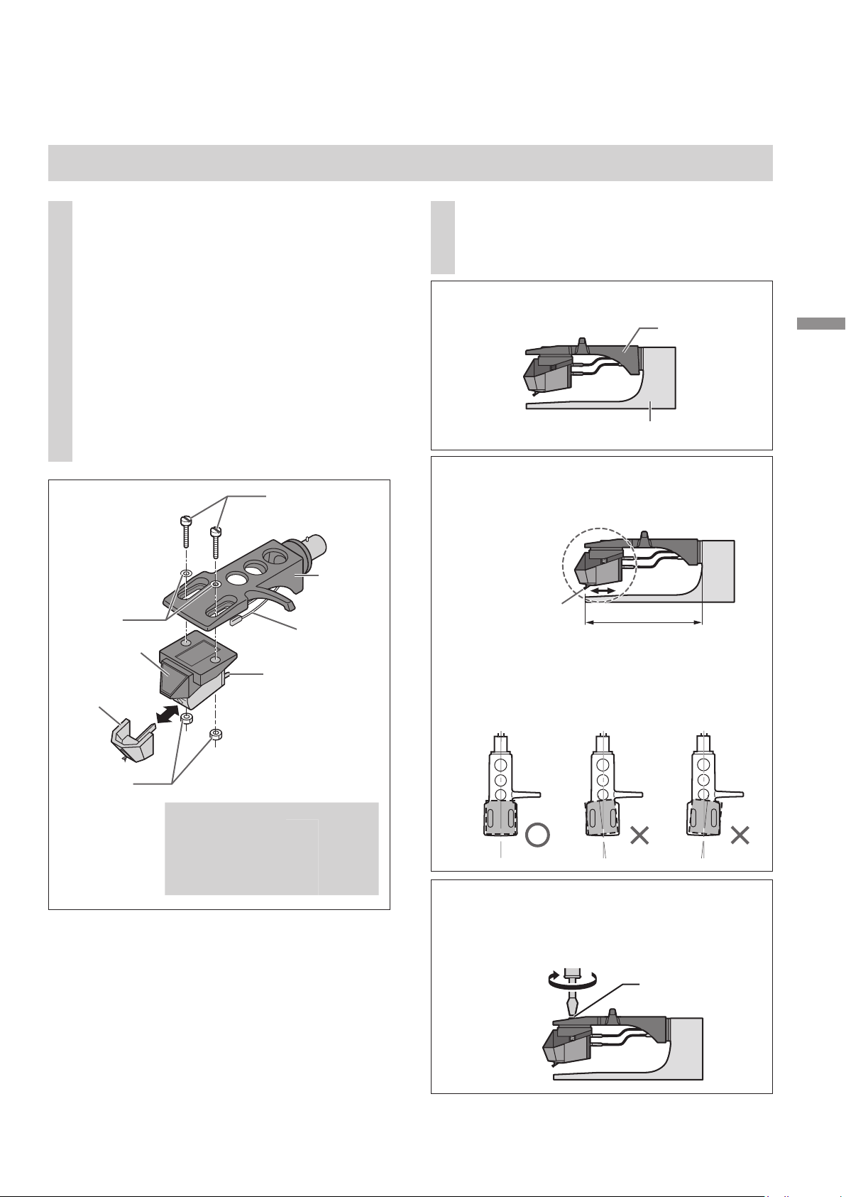
Fixation de la cellule
Fixer provisoirement une cellule
1
(achetée en magasin).
Suivre les instructions d'installation de
la cellule pour la fixer correctement à la
coquille, et serrer légèrement les vis.
zSi des vis de fixation sont incluses avec
la cellule, les utiliser.
zLors de la lecture de 78 tours, utiliser une
cellule spécifique pour 78 tours.
zUtiliser un mini tournevis plat (4 mm
[5/32 po]).
zVeiller à ne pas toucher l'extrémité de la
pointe de lecture.
(Exemple)
Rondelles
Cellule
Pointe de
lecture
Vis pour cellule
de lecture
Fil
conducteur
Connecteur
Coquille
Réglage du porte-à-faux.
2
Utiliser la jauge du porte-à-faux incluse.
Fixer la jauge à la coquille.
Coquille
Jauge du porte-à-faux
k
Déplacer la cellule pour aligner l'extrémité
de la pointe de lecture avec l'extrémité de
la jauge.
Extrémité de la
pointe de lecture
z La cellule doit être parallèle à
la coquille lorsque l'on regarde
latéralement ou du dessus (l'illustration
présente la vue du dessus).
52 mm
(2-3/64 po)
Démarrage
Écrous
(Fil conducteur) (Connecteur)
Rouge
Vert
Blanc
Bleu
R+ (Rouge)
R- (Vert)
L+ (Blanc)
L- (Bleu)
Serrer les vis de la cellule.
l
z Veiller à ne pas laisser la cellule glisser
hors de l'emplacement.
Vis pour cellule de
lecture
Le porte-à-faux peut être réglé de façon
optimale.
Français (Canada
(39)
13
)
Page 40
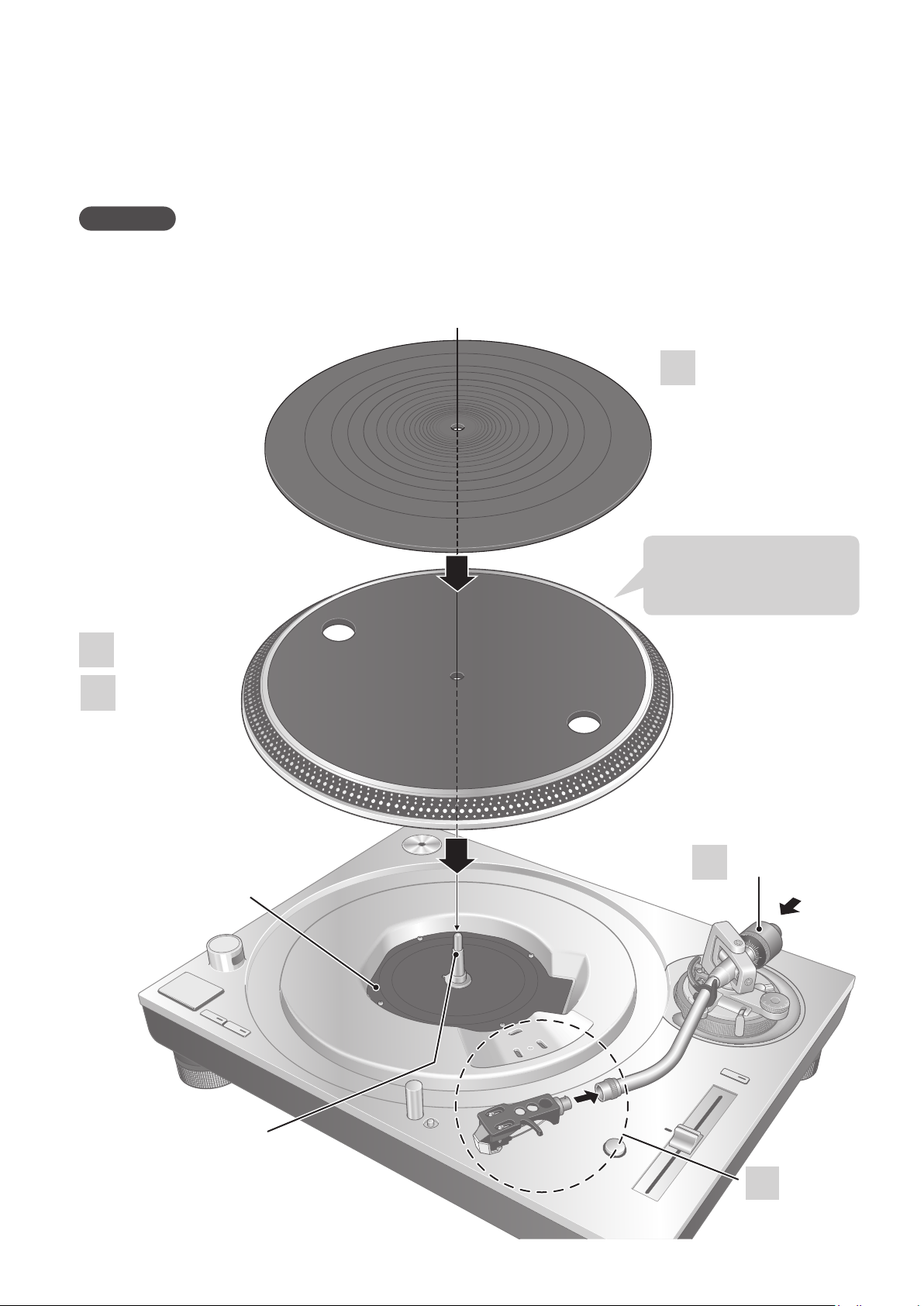
Assemblage du tourne-disque
Dans le but de prévenir tout risque de dommages pendant l’expédition, le tourne-disque a été démonté.
Assembler le tourne-disque dans l’ordre suivant.
Attention
zNe pas brancher le cordon d’alimentation avant d’avoir terminé l’assemblage.
zLors du montage du plateau, empêcher tout matériau étranger de pénétrer entre l'unité principale
et le plateau.
zNe pas toucher ou gratter la table.
(suite)
Tapis du plateau
3
Manipuler avec
précaution car il
est lourd.
1
2
Plateau
Table
Contrepoids
5
Axe central
(40)
14
Français (Canada
Coquille
4
)
Page 41
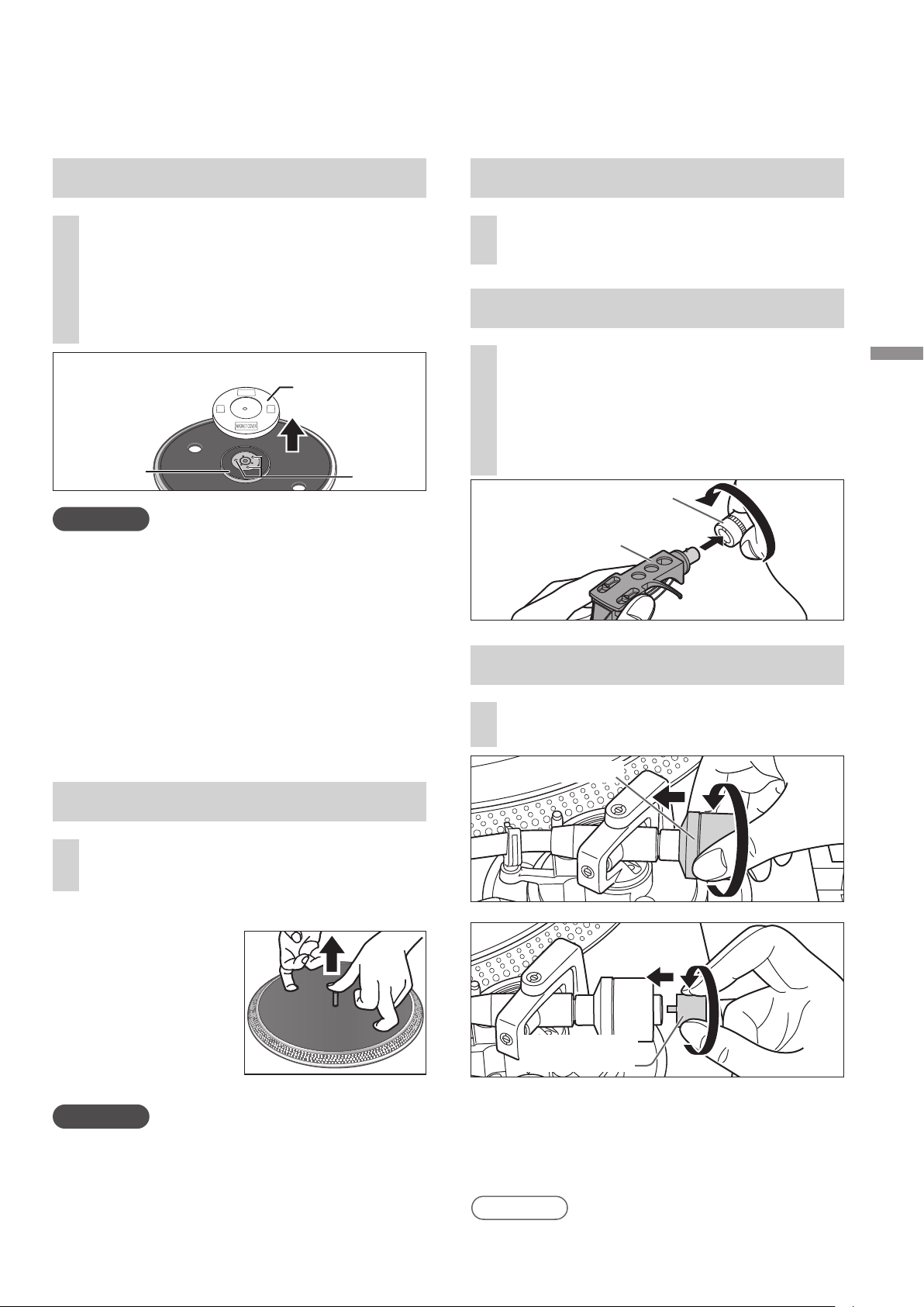
Avant de fixer le plateau
Mise en place du tapis du plateau
Retirer le couvercle aimanté du
1
plateau.
zL'aimant et son couvercle se trouvent à
l'arrière du plateau.
Retirer le couvercle aimanté avant de le
fixer à l'unité principale.
Côté arrière du plateau
Couvercle
aimanté
Aimant
Attention
zGarder tout objet magnétique sensible,
telle une carte magnétique ou une montre,
éloigné de l'aimant.
zEmpêcher le plateau de heurter l'unité
principale ou de tomber. Empêcher que de
la poussière ou de la poudre de fer adhère à
l'aimant sur la face arrière.
zNe pas toucher les vis de fixation (trois
emplacements) du plateau. La performance
nominale ne peut être garantie si elles ne
sont pas convenablement positionnées.
Vis de
fixation
Déposer le tapis du plateau sur le
3
plateau.
Fixation de la coquille
Fixer la coquille avec la cartouche
4
dans le bras de lecture.
Maintenir la coquille horizontale
et serrer l'écrou de blocage.
zVeiller à ne pas toucher l'extrémité de la
pointe de lecture.
Écrou de blocage
Coquille
Fixation du contrepoids
Fixer le contrepoids à l’arrière du
5
bras de lecture.
Démarrage
Montage du plateau
Fixer lentement le plateau sur
2
l'axe central.
Pour enlever le plateau
Comme le montre
la figure de droite,
placer les doigts
dans les deux trous
sur le plateau,
maintenir l'axe
central abaissé et
retirer le plateau vers
le haut.
Attention
zSoyez prudent lorsque vous manipulez le
plateau, car il est lourd.
zVeillez à ce que vos doigts ne restent pas
coincés.
zEssuyez les traces de doigts ou la poussière
avec un chiffon doux.
Contrepoids
Contrepoids
supplémentaire
zFixer le contrepoids auxiliaire inclus à l'arrière
du bras de lecture en fonction du poids de
la cellule. Pour les diverses gammes de poids
des cellules réglables, voir « Plage applicable
pour le poids de la cellule ». (27)
Nota
zL'intérieur du contrepoids est graissé.
(41)
15
Français (Canada
)
Page 42

Raccordements et installation
zMettre tous les appareils hors marche et débrancher le cordon d'alimentation de la prise avant
d'effectuer tout branchement.
zNe brancher les cordons d’alimentation qu’après avoir terminé tous les autres raccordements.
zVeiller à connecter le fil de terre PHONO. Sinon des ronflements peuvent se produire.
zSe reporter également au mode d'emploi de l'appareil connecté.
Connecter le câble PHONO
1
et le fil de terre PHONO aux
connecteurs d'entrée PHONO de
l'équipement connecté.
zSi l’amplificateur connecté n’est pas
muni de connecteurs d'entrée PHONO,
vous n'obtiendrez ni le volume ni le
rendu sonore adéquat.
Brancher le cordon
2
d’alimentation.
zVérifier le courant minimal de la prise
d’alimentation de l'équipement connecté
avant d'y brancher cet appareil.
(Ce tourne-disque consomme 11 W.)
Connexion à un amplificateur intégré ou système de composants
Amplificateur (vendu séparément)
EARTH
PHONOPHONO
Arrière de l'unité principale
LR
LR
Câble PHONO
Fil de terre PHONO
Nota
zBien que l'interrupteur d'alimentation soit en position « OFF », le tourne-disque n'est pas
complètement déconnecté du secteur. Retirer la fiche de la prise secteur si le tourne-disque n'est
pas utilisé pendant une période de temps prolongée.
Installer le tourne-disque de manière que la prise puisse être facilement retirée.
Cordon
d'alimentation
Vers une prise de
courant de la maison
(42)
16
Français (Canada
)
Page 43
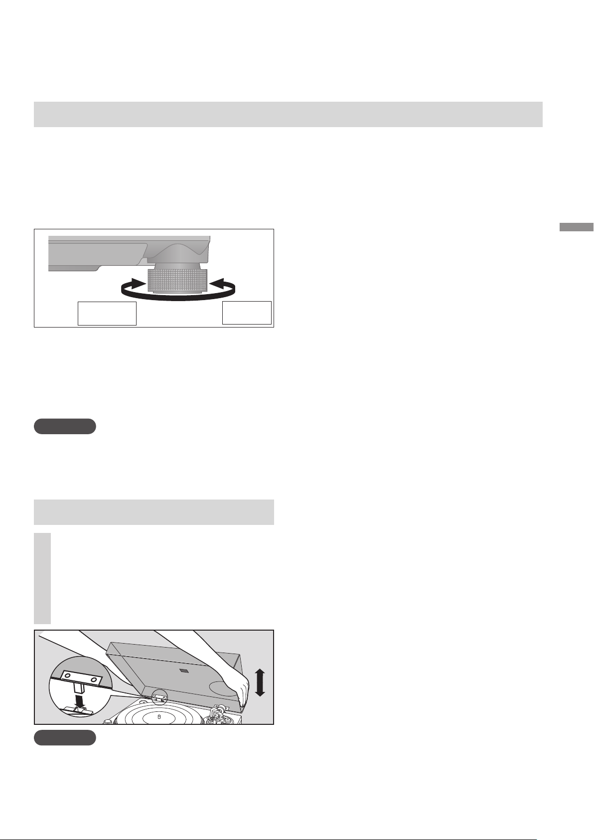
Installation
Installer le tourne-disque sur une surface de
niveau, à l’abri de toute vibration.
Éloigner le tourne-disque le plus loin possible
des enceintes.
Réglage de la hauteur pour mettre
le tourne-disque au niveau
Augmente
la hauteur
Soulever le tourne-disque pour tourner les
isolateurs et régler la hauteur.
Dans le sens des aiguilles d'une montre :
z
Réduit la hauteur.
Dans le sens inverse des aiguilles d'une
z
montre : Augmente la hauteur.
Attention
zNe pas tourner trop loin les isolateurs.
zCela peut les amener à se détacher ou peut
les endommager.
Réduit la
hauteur
Remarques pour l'installation
zAvant de déplacer le tourne-disque, retirer
tous les périphériques connectés et couper
l'alimentation.
zProtéger l’appareil contre les rayons directs du
soleil, la poussière, l’humidité et les sources de
chaleur.
zIl est possible que l’appareil capte les
interférences d’une radio, s'il y en a une à
proximité. Éloigner le plus possible le tournedisque d'une radio.
zNe pas installer le tourne-disque sur une source
de chaleur.
Éviter tout endroit présentant de grandes
z
variations de température.
zÉviter tout endroit présentant fréquemment de
la condensation.
zÉviter tout endroit instable.
zNe pas placer d'objet sur le tourne-disque.
zNe pas installer le tourne-disque dans un espace
confiné tel qu'une étagère.
zInstaller le tourne-disque dans un emplacement
suffisamment éloigné des murs ou d'autres
dispositifs pour assurer un rayonnement
thermique efficace de l'intérieur de l'appareil.
zS'assurer que le matériau de l'emplacement
d'installation est suffisamment solide pour
supporter le poids du tourne-disque.
zNoter que le tourne-disque peut être
endommagé par la fumée de cigarette ou
l'humidité d'un humidificateur à ultrasons.
Démarrage
Condensation
Mise en place du couvercle
Maintenir le couvercle avec les
1
deux mains et l'insérer dans les
pièces de fixation du couvercle
( 11) sur le tourne-disque.
zPour retirer le couvercle, le garder ouvert
et le soulever à la verticale.
Attention
Ramener le bras de lecture sur le reposoir et le fixer avec l'agrafe du bras avant d'installer ou de retirer
z
le couvercle.
zEn insérant le couvercle, éviter que l'extrémité des charnières ne vienne heurter et endommager l'unité
principale.
Penser à l'exemple d'une bouteille froide sortie
d'un réfrigérateur. Si elle est laissée dans une pièce
pendant un certain temps, de la condensation se
forme sur la surface de la bouteille. Ce phénomène
est appelé « condensation ».
zConditions provoquant de la condensation
Changement rapide de température (provoqué
par un déplacement d'un endroit chaud
à un endroit froid ou vice versa, par un
refroidissement ou un chauffage rapide, ou une
exposition directe à l'air froid)
Une forte humidité dans une pièce avec
beaucoup de vapeur, etc.
Saison des pluies
zLa condensation peut endommager le tourne-
disque. Si cela se produit, mettre le tourne-
disque hors marche et attendre qu'il s'adapte à
la température ambiante (environ 2 à 3 heures).
(43)
Français (Canada
17
)
Page 44

Réglage
Équilibrage horizontal
Préparatifs
zTout d'abord, retirer le couvercle.
zRetirer le couvercle de la pointe de lecture,
en prenant bien soin de ne pas l’abîmer, puis
dégager l’agrafe du bras.
zAbaisser le levier de positionnement du bras.
Mettre la commande d’antipatinage sur « 0 ».
z
Libérer le bras de lecture du
1
reposoir et régler l'équilibre
horizontal en tournant le
contrepoids.
Maintenir le bras de lecture et tourner
le contrepoids dans le sens de la flèche
pour régler l'équilibre jusqu'à ce que le
bras soit horizontal le plus possible.
zPrendre soin de ne pas
laisser l'extrémité de la pointe de lecture
toucher le
plateau ou l'unité
principale.
Contrepoids
Tenir
ici pour
tourner
Force d’appui de la pointe de lecture
Préparatifs
zTout d'abord, retirer le couvercle.
zRamener le bras sur le reposoir et le fixer
avec l'agrafe du bras.
Tourner la commande de la force
1
d'appui de la pointe de lecture
jusqu'à ce que « 0 » arrive sur la
ligne centrale de l'arrière du bras
de lecture.
zTenir le contrepoids
pendant ce réglage.
Contrepoids
Repère
central
Commande de la
force d’appui de la
pointe de lecture
Tenir ici
pour
tourner
Agrafe du bras
Reposoir
positionnement du bras
Commande d’antipatinage
(44)
18
Levier de
Français (Canada
Agrafe du bras
Nota
zSe reporter au guide de l'utilisateur de la
pointe de lecture pour connaître la force
d'appui appropriée de la pointe de lecture.
Le bras de lecture
équilibré est parallèle au
plateau.
Le contrepoids est trop
en avant.
Le contrepoids est trop
en arrière.
)
Page 45

Antipatinage
Tourner le contrepoids de
2
manière à régler la force d'appui
de la pointe de lecture appropriée
pour la cellule.
zLa commande de la force d'appui de la
pointe de lecture tourne conjointement
avec le contrepoids.
zTourner jusqu'à ce que la ligne centrale
pointe vers la force d'appui de la pointe
de lecture appropriée.
Contrepoids
Tenir ici
pour
tourner
Tournent
ensemble
Tourner la commande
1
antipatinage pour la régler sur
la même valeur que celle de la
commande de la force d'appui de
la pointe de lecture.
0
1
3
2
Démarrage
Repère
central
Nota
zPour des forces d'appui de la pointe de
lecture de 3 g et plus, régler la commande
antipatinage sur « 3 ».
(45)
19
Français (Canada
)
Page 46

Réglage
0
(suite)
Hauteur du bras de lecture
Ne faire ce réglage que si la cellule utilisée le
rend nécessaire.
Préparatifs
zMettre un disque en place sur le plateau.
Dégager le bras de son agrafe.
1
Verrou du bras
Régler la hauteur à l'aide de la
2
bague de réglage de hauteur du
(Dégagé)
(Verrouillé)
bras de lecture.
Régler la hauteur du bras jusqu'à ce que le
bras de lecture soit parallèle au disque.
Se reporter au tableau ci-dessous pour
trouver le repère de l'emplacement
appropriée pour la hauteur de la cellule.
(pour la coquille fournie)
Hauteur de la
cellule
(H) en millimètres
17
18
19
20
21
22
23
Position de la
commande
0
1
2
3
4
5
6
Après le réglage de la hauteur du
3
bras, verrouiller le bras de lecture
en tournant le verrou du bras.
zS'assurer de tourner le bouton de
verrouillage du bras jusqu'au bout,
comme indiqué sur la figure ci-dessous.
Il faudra peut-être appliquer une certaine
force pour y parvenir.
A
T
K
I
N
S
-
G
I
T
N
Si vous ne connaissez pas la
A
3
hauteur de la cellule de lecture(H)
ou lorsque vous n'utilisez pas la
coquille porte-cellule fournie
Retirer le couvercle de la pointe de lecture,
en prenant bien soin de ne pas l’abîmer, puis
dégager l’agrafe du bras.
Abaisser le levier de positionnement du bras,
reposer la pointe de lecture sur un disque et
régler la commande de la hauteur jusqu'à
ce que le bras de lecture et le disque soient
parallèles.
zSi la hauteur de la cellule de lecture (H) est
trop basse pour les rendre parallèles entre
elles, ajouter un « espaceur de cellule de
lecture » (non fourni).
Parallèlement à un disque
k
Tourner la bague
de commande de
hauteur du bras pour
aligner le repère de
position avec la ligne
de repérage.
De 0 à 6 mm
(0 à 15/64 po) sont
indiqués sur la bague
de commande de
hauteur du bras de
lecture.
(46)
20
Français (Canada
3
Ligne de repérage
Bague de réglage
de hauteur du bras
de lecture
)
Attention
4
Veiller à ne pas endommager l'extrémité de la
z
pointe de lecture.
zNe pas utiliser le produit sans que le bras ne
soit verrouillé.
zPour un réglage plus fin, utiliser un niveau
(non inclus) pour régler la hauteur du bras
de sorte que la cellule de lecture devienne
parallèle au disque.
Page 47

Hauteur du lève-bras
Procéder à un ajustement en fonction de votre
cellule, si nécessaire.
Préparatifs
Mettre un disque en place sur le plateau.
Retirer le couvercle de la pointe de lecture,
en prenant bien soin de ne pas l’abîmer, puis
dégager l’agrafe du bras.
Soulever le levier de positionnement du bras
et déplacer le bras au-dessus de la surface du
disque.
Réglage de la vitesse de
démarrage/freinage du plateau
Bouton FREIN
S (lent)
F (Rapide)
Témoin de confirmation
Bouton de couple
L (Bas)
H (Élevé)
Appuyer légèrement au centre du bouton.
Vitesse de démarrage
BRAKE
S
L
TORQUE
F
H
Démarrage
Vérifier la hauteur du lève-bras
1
(distance entre l'extrémité de la
pointe de lecture et la surface
du disque). Si un réglage est
nécessaire, passer à l'étape
La hauteur du lève-bras est réglée par
défaut de 8 à 13 mm
Ramener le bras sur le reposoir
2
et le fixer avec l'agrafe du bras.
(5/16 à
33/64 po).
Tourner la vis de réglage du lèvebras.
Tourner la vis dans le sens des aiguilles
d'une montre pour abaisser le lève-bras.
Tourner la vis dans le sens inverse des
aiguilles d'une montre pour lever le lèvebras.
Vis de réglage
du lève-bras
Lève-bras
1
Vous avez le choix entre trois options de
vitesse de démarrage (le temps d'atteindre
la vitesse constante) après avoir appuyé sur
[START·STOP] et le gain de couple à la vitesse
.
2
constante.(Réglage d'usine : 3)
[3] Démarrage rapide
〜
[1] Démarrage lent
Le témoin de confirmation clignote le nombre de
fois spécifié en fonction du réglage en cours lorsque
vous appuyez sur le bouton de couple H ou L.
Pour modifier le réglage, appuyez sur le bouton de
couple H ou L pendant que le témoin est allumé.
Exemple : Si le réglage actuel est [3] et que vous
appuyez deux fois sur le bouton L, le
réglage passera sur [1].
Après avoir appuyé sur le bouton de couple, le
témoin de confirmation clignote le nombre de fois
spécifié pour afficher le nouveau réglage, reste
allumé deux secondes, puis s'éteint.
Vitesse de freinage
Vous pouvez choisir parmi cinq options de vitesse de
freinage pour arrêter le plateau après avoir appuyé
sur [START·STOP]. (Réglage d'usine : 5)
[5] S'arrête rapidement
〜
[1] S'arrête lentement
Le témoin de confirmation clignote le nombre
de fois spécifié en fonction du réglage en cours
lorsque vous appuyez sur le bouton de freinage F
ou S.
Pour modifier le réglage, appuyez sur le bouton de
freinage F ou S pendant que le témoin est allumé.
Exemple : Si le réglage actuel est [5] et que vous
appuyez deux fois sur le bouton S, le
réglage passera sur [3].
Après avoir appuyé sur le bouton de freinage, le
témoin de confirmation clignote le nombre de fois
spécifié pour afficher le nouveau réglage, reste
allumé deux secondes, puis s'éteint.
Français (Canada
(47)
21
)
Page 48
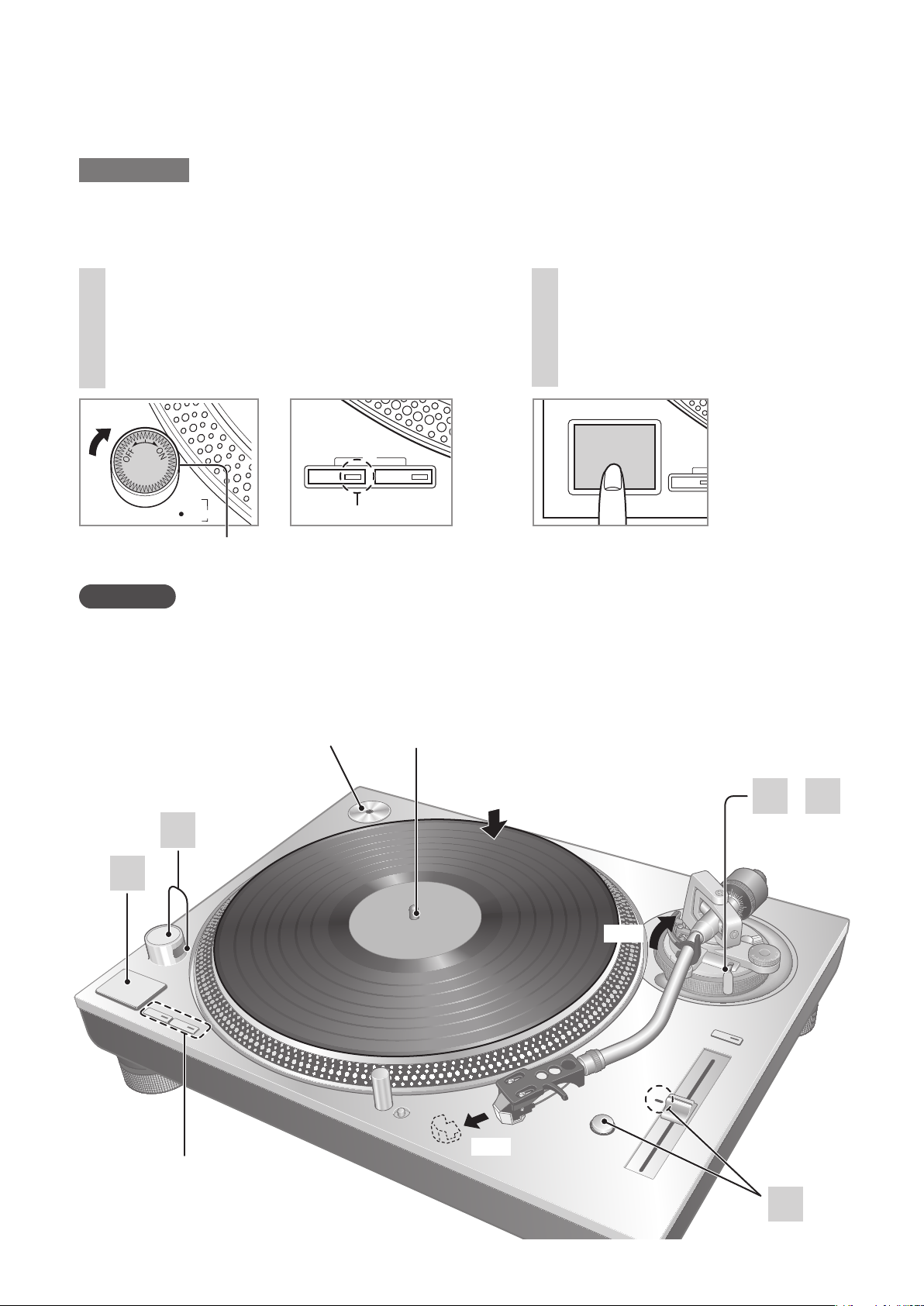
Lecture de disques
・
Préparatifs
1 Mettre un disque (non inclus) en place sur le plateau.
2 Retirer le couvercle de la pointe de lecture et dégager l’agrafe.
Tourner [ON/OFF] pour mettre
1
l'appareil en marche.
La lumière stroboscopique s'allume. 33-1/3
tours/min est automatiquement sélectionné
et l’indicateur [33] s’allume.
78
33 45
+6.4
・
3.3
・
0
%
-
3.3
Lampe
stroboscopique
Attention
N'appuyez pas sur [START-STOP] lorsque le plateau est retiré.
Si vous avez accidentellement appuyé sur [START-STOP].
z L'indicateur du bouton de sélection de vitesse ([33] ou [45]) commence à clignoter.
S'ilclignote,tournez[ON/OFF]pourmettrel'unitéhorsmarche,xezleplateau,puistournez
[ON/OFF]pourmettrel'unitéenmarche.
Indicateur
Appuyer sur [START-STOP].
2
La rotation du plateau s’amorce.
START・STOP
33
Adaptateur pour 45 tours
prolongé
1
2
Sélecteurs de vitesse
Indicateurs
Axe central
1
2
2
4
·
5
3
(48)
22
Français (Canada
)
Page 49
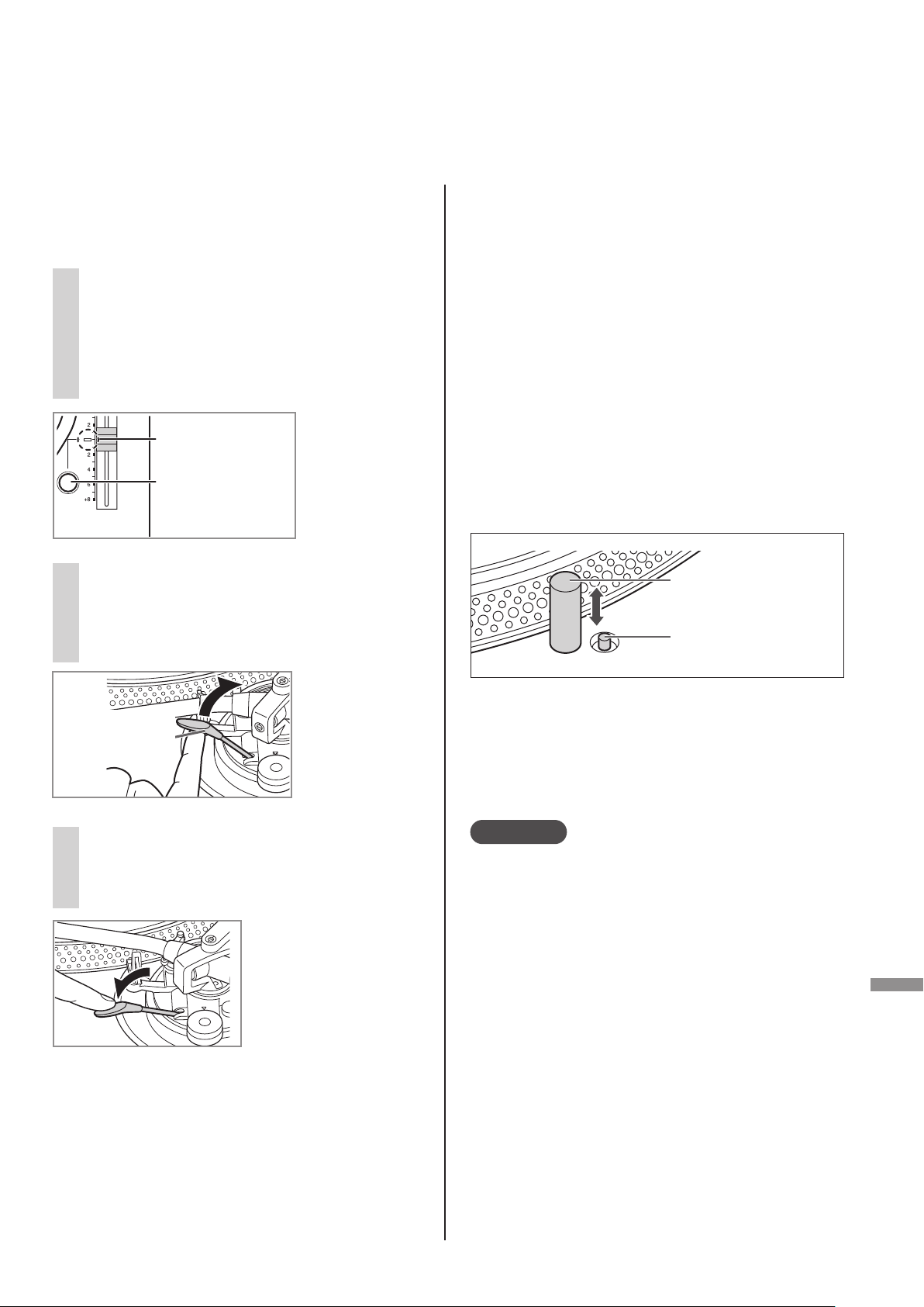
Appuyer sur [RESET] pour allumer
PITCH ADJ
RESET
3
la diode bleue de commande de
hauteur tonale.
L'appareil lit à une vitesse de rotation
prédéfinie (33-1/3, 45 ou 78 tr/min)
indépendamment de la position [pitch adj].
Indicateur de
variation de la
vitesse (diode bleue)
Touche de
RÉTABLISSEMENT
zRéglage précis
pour la hauteur
tonale
( 24)
Après la fin de la lecture
Lever le levier de positionnement du bras,
ramener le bras de lecture sur le reposoir et
abaisser le levier de positionnement du bras.
Appuyer sur [START-STOP].
k
Le frein électrique arrête la rotation du
plateau en douceur.
Tourner [ON/OFF] pour mettre l'appareil hors
l
marche.
Fixer le bras de lecture avec l'agrafe du bras.
Remettre le couvercle de la pointe de lecture
(pour protéger l'extrémité de la pointe de
lecture).
Pour éclairer la pointe de lecture
L'extrémité de la pointe de lecture est éclairée
pendant la lecture.
Soulever le levier de
4
positionnement du bras et
déplacer le bras au-dessus de la
surface du disque.
Levier de
positionnement
du bras
Abaisser lentement le levier de
5
positionnement du bras.
Le bras de lecture s'abaisse lentement.
La lecture
commence.
Pour interrompre
momentanément la lecture
Lever le levier de positionnement du bras.
zLa pointe de lecture s’élève au-dessus du
disque.
zPour reprendre la lecture, abaisser le levier de
positionnement du bras.
Éclairage de la pointe
de lecture
Interrupteur d'éclairage
de la pointe de lecture
Appuyer sur l’interrupteur d'éclairage de la
pointe de lecture.
zL'éclairage de la pointe de lecture (diode
blanche) sort et éclaire la pointe de lecture.
zAppuyer sur l'éclairage de la pointe de lecture
pour éteindre l'éclairage.
Attention
Appuyez fermement sur l’interrupteur
d'éclairage de la pointe de lecture. Si vous
appuyez légèrement sur l'interrupteur,
l'éclairage peut s'activer mais ne pas se
soulever.
Lors de la lecture de 45 tours prolongé
zAppuyer sur le bouton de sélection de vitesse
[45] ([45] s'allume).
zMonter l'adaptateur pour 45 tours prolongé
sur l'axe central.
Lors de la lecture de 78 tours
zAppuyer en même temps sur les touches de
sélection de vitesse [33] et [45] (78 tr/min :
[33] et [45] s'allument).
Lors de l'utilisation d'un stabilisateur
de disque (non inclus)
zConsulter le manuel d'instruction du
stabilisateur de disque.
zPoids maximum : 1 k
g
(49)
Français (Canada
Lecture
23
)
Page 50
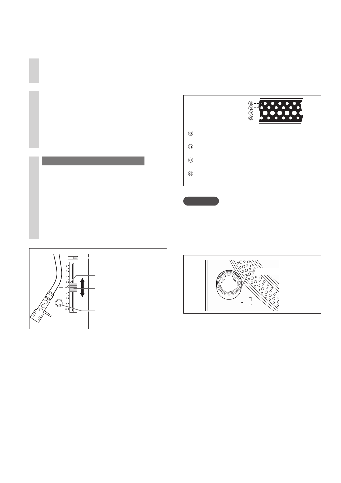
Commande de hauteur tonale
PITCH ADJ
RESET
×
2
vitesse de rotation)
(réglage précis de la
Appuyer sur [RESET] pour
1
éteindre la diode bleue.
Appuyer sur le sélecteur de plage
2
de la vitesse de rotation pour
choisir la plage de vitesse de
rotation.
z[×2] allumé : ±16 %
z[×2] éteint : ±8 %
3
Pendant que le plateau tourne
Faire glisser [PITCH ADJ].
zLa hauteur tonale peut être réglée entre
environ –8 % et +8 % ou entre environ
–16 % et +16 % en fonction de votre
sélection.
zLes nombres indiquent les pourcentages
approximatifs de variation par rapport à
votre réglage.
Sélecteur de plage de la
vitesse de rotation
Indicateur de variation de
la vitesse (diode bleue)
Réglage de la hauteur
tonale
Touche de
RÉTABLISSEMENT
Indication de la hauteur tonale
Les quatre rangées de miroirs stroboscopiques
sur le pourtour du plateau peuvent aider à
régler la hauteur tonale.
Repères
stroboscopiques
Variation de +6,4 % lorsque cette rangée
semble immobile
Variation de +3,3 % lorsque cette rangée
semble immobile
Vitesse normale du plateau (33-1/33, 45 ou 78
tr/min) à l'arrêt
Variation de -3,3 % lorsque cette rangée semble
immobile
Attention
Les miroirs stroboscopiques sont éclairés par
un éclairage stroboscopique (diode bleue)
synchronisé avec la fréquence précise de la
commande numérique.
Toujours utiliser la diode bleue pour mesurer la
vitesse de rotation.
Lampe stroboscopique
+6.4
・
3.3
・
0
%
-
3.3
・
Rétablissement de la vitesse
nominale
Appuyer sur [RESET].
La diode bleue s'allume et la vitesse de
rotation revient immédiatement à une valeur
prédéterminée indépendamment de la position
de [PITCH ADJ].
(33-1/3, 45 ou 78 tr/min)
zDEL bleue allumée : Réglée à la valeur
prédéfinie.
zDEL bleue éteinte : Peut être réglée avec
[PITCH ADJ].
(50)
24
Français (Canada
)
Page 51
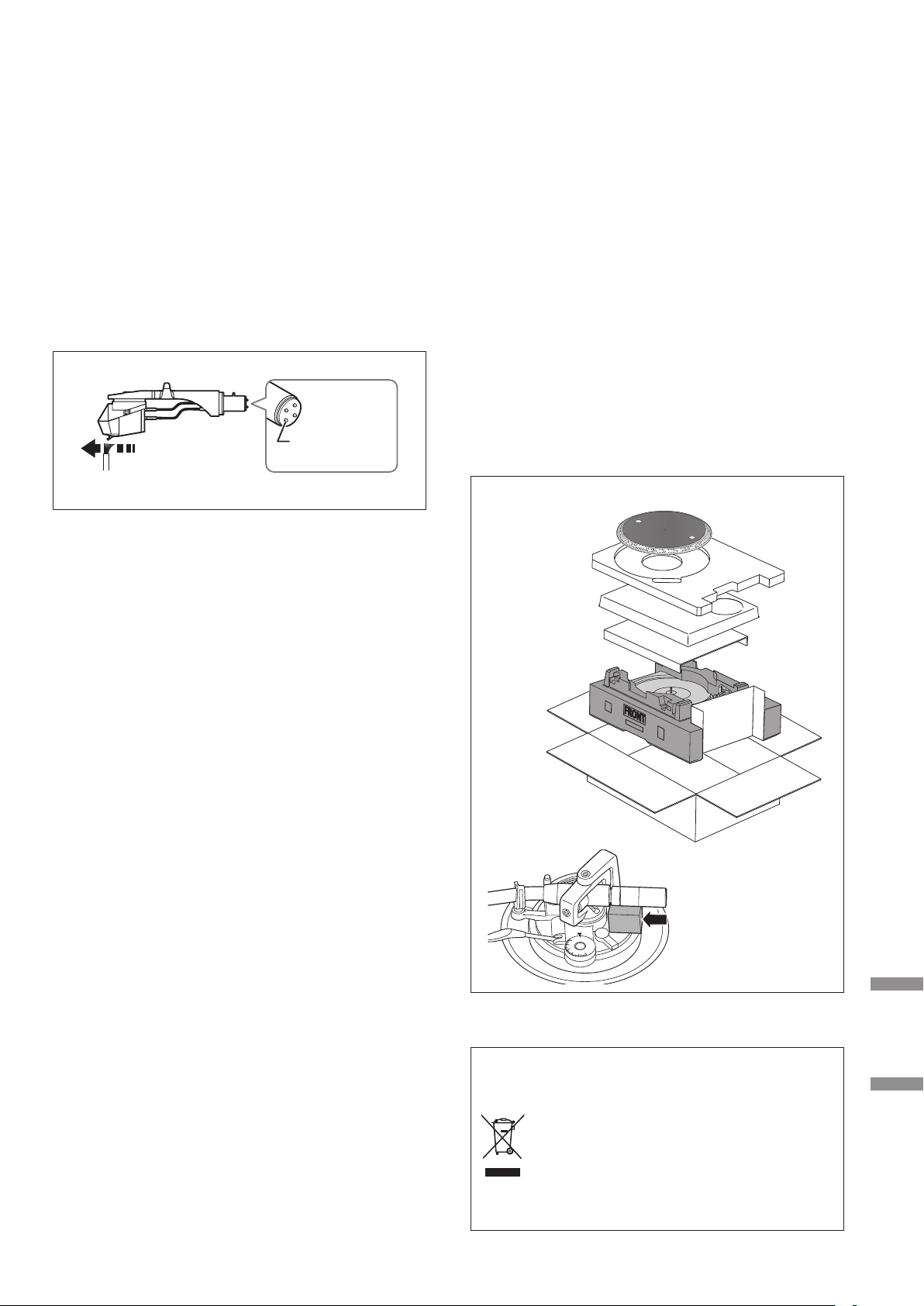
Entretien
Entretien des pièces
Enlever toute poussière sur la pointe de
lecture et sur le disque.
zEnlever la coquille avec la cellule et nettoyer
la pointe de lecture à l'aide d'un pinceau
doux. Brosser depuis la base jusqu’à la
pointe.
zUtiliser un nettoyant pour disque pour garder
vos disques propres.
Connecteurs
de la coquille
Essuyer occasionnellement les connecteurs
de la coquille.
Essuyer les connecteurs de la coquille avec un
chiffon doux et fixer la coquille sur le bras de
lecture.
Transport du tourne-disque
Remettre l’appareil dans son emballage
d’origine.
Conserver les matériaux d'emballage après avoir
sorti les marchandises.
Si l’emballage d’origine n’a pas été conservé,
procéder comme suit :
zRetirer le plateau et le tapis, et bien les
empaqueter.
zRetirer la coquille et le contrepoids du bras de
lecture et les envelopper soigneusement.
zFixer le bras de lecture avec l'agrafe de bras
et l'attacher avec du ruban adhésif.
zEnvelopper l'unité principale dans une
serviette ou du papier.
Reconditionnement
Baisser le volume de l'amplificateur ou
mettre l'amplificateur hors tension avant de
fixer ou de retirer la coquille.
Si la coquille est retirée alors que le volume
n’est pas coupé, les haut-parleurs pourraient
être endommagés.
Nettoyage du couvercle et du
boîtier
Essuyer le couvercle et le boîtier avec un
chiffon doux.
Ne pas toucher la table pendant le
nettoyage. Sinon, le lecteur pourrait ne pas
fonctionner.
Lorsque la saleté est tenace, essorer un chiffon
humide pour enlever la saleté, puis essuyer avec
un chiffon doux.
zNe pas utiliser de solvants, benzène, diluant,
alcool, détergent de cuisine, liquide d'essuieglace, etc. Cela pourrait déformer le boîtier
externe ou décoller le revêtement.
zNe pas essuyer le couvercle pendant la
lecture d’un disque.
Cela peut provoquer de l'électricité statique.
Ces parasites peuvent attirer le bras de
lecture vers le couvercle.
Avant le
reconditionnement,
retirer le contrepoids
0
1
3
2
Symbole WEEE
Mise au rebut du produit en dehors des
pays de l'UE
Ce symbole est uniquement valable
dans l'UE.
Contacter un service gouvernemental
local ou votre revendeur pour savoir
comment mettre ce produit au rebut
convenablement.
d'équilibrage et
insérer le support de
bras de lecture sous
le bras de lecture.
Lecture Entretien
(51)
25
Français (Canada
)
Page 52

Guide de dépannage
Avant de faire appel au service, procédez aux vérifications ci-dessous. Si vous avez un doute
concernant certains des points de vérification, ou si les solutions proposées dans le tableau ne
résolvent pas le problème, communiquez avec votre revendeur.
Pas d’alimentation.
zLe cordon d'alimentation est-il branché?
¨
Brancher le cordon en prenant soin d’introduire la fiche à fond dans la prise. ( 16)
Aucun son n’est entendu.
Le volume est faible.
zLes connexions aux prises PHONO de l’amplificateur/récepteur sont-elles adéquates?
¨
Connecter les câbles PHONO aux prises PHONO de l'amplificateur. ( 16)
Les signaux des canaux gauche et droit sont inversés.
zLes connexions du câble de raccordement stéréo à l'amplificateur ou au récepteur sont-elles
inversées?
¨
Vérifier tous les raccordements. ( 16)
zLes connexions des fils conducteurs de la coquille aux connecteurs de la cellule sont-elles
adéquates?
¨
Vérifier tous les raccordements. ( 13)
Un ronflement se produit pendant la lecture.
zLes câbles stéréo se trouvent-ils près d’appareils électriques ou de leur cordon d'alimentation?
¨
Éloigner tout appareil électrique (et leur cordon d’alimentation) du tourne-disque.
zLe fil de terre est-il raccordé?
¨
S’assurer que le fil de terre est bien raccordé. ( 16)
La lumière stroboscopique ou le voyant bleu clignote.
Effectuer l'opération suivante lorsque la lumière stroboscopique ou le voyant bleu clignote. Le
symptôme peut être amélioré.
Tourner [ON/OFF] sur OFF.
k
Débrancher le cordon d'alimentation, attendre trois secondes, puis rebrancher la fiche.
Tourner [ON/OFF] sur ON et appuyer sur
l
[START-STOP] pour faire tourner le plateau.
zSi la lumière stroboscopique ou le voyant bleu clignote à nouveau, vérifier lequel clignote et
contacter notre représentant pour le service après-vente.
(52)
26
Français (Canada
)
Page 53

Spécifications
Divers
Alimentation 120 V c.a., 60 Hz
Consommation 11 W (EN MARCHE)
0,2 W (HORS MARCHE)
Dimensions
(L×H×P)
Poids Environ 11,5 kg
Température de
fonctionnement
Humidité relative 35 % à 80 %
Section tourne-disque
Type Système de plateau à
Méthode
d'entraînement
453 x 173 x 372 mm
17-27/32 × 6-13/16 × 14-21/32 po
(
(25,4 lb
0 °C à +40 °C
(+32 °F à +104 °F)
(sans condensation)
entraînement direct
(manuel)
Entraînement direct
)
Section bras de lecture
Type Type statique équilibré
Longueur
effective
Porte-à-faux 15 mm (19/32 po)
)
Angle d’erreur de
poursuite
Angle correcteur
d'erreur de piste
Plage de réglage
de la hauteur
Plage de réglage
de la force
d’appui de la
pointe de lecture
Contrepoids de la
coquille
230 mm (9-1/16 po)
Moins de 2° 32' (au début
d’un disque de 30 cm (12 po))
Moins de 0° 32' (à la fin d’un
disque de 30 cm (12 po))
22°
0 - 6 mm (0 - 15/64 po)
0 – 4 g (lecture directe)
Environ 7,6
g
Moteur Moteur c.c. sans balais
Plateau Aluminium moulé sous
pression
Diamètre : 332 mm
(13-5/64 po)
g
Vitesses de
rotation
Plage de hauteur
tonale
Couple de
démarrage
Caractéristiques
d’établissement
Système de
freinage
Poids : Env. 2,5 k
(5,51 lb)
(y compris une feuille de
caoutchouc)
33-1/3, 45 et 78 tr/min
± 8 % et ± 16 %
2,2 kg-cm (1,91 lb-po)
0,7 s, pour passer de l’arrêt
à 33-1/3 tr/min
Frein électronique
Plage applicable
pour le poids de
la cellule
Connecteurs de la
coquille
Sujet à changements sans préavis.
(Sans le contrepoids
auxiliaire)
5,6 à 12,0
14,3 à 20,7 g (y compris la
coquille)
(Avec le contrepoids
supplémentaire)
10,0 à 16,4
18,7 à 25,1 g (y compris la
coquille)
4 broches 1,2 mm
g
g
φ
Entretien
Pleurage /
scintillement
Ronflement en
basse fréquence
0,025 % eff. pondéré (JIS
C5521)
78 dB (CEI 98A pondéré)
(53)
27
Français (Canada
)
Page 54

Autres
Certificat de garantie limitée (SEULEMENT POUR LE CANADA)
Autres
Certificat de gar antie limitée (S EULEMENT POU R LE CANAD A)
Panasonic Canada Inc.
5770, Ambler Drive, Mississauga (Ontario) L4W 2T3
PRODUIT TECHNICS – GARANTIE LIMITÉE
La présente garantie n’est fournie qu’à l’acheteur original d’un des produits de marque Technics indiqués plus haut,
ou à la personne l’ayant reçu en cadeau, vendu par un détaillant Panasonic agréé au Canada et utilisé au Canada. Le
GARANTIES IMPLICITES DU CARACTÈRE ADÉQUAT POUR LA COMMERCIALISATION ET UN USAGE PARTICULIER. PANASONIC
Emballez soigneusement, de préférence dans son carton d’origine, et expédiez, franco de port, suffisamment assuré.
Autres
Certificat de garantie limitée (SEULEMENT POUR LE CANADA)
Autres
Certificat de gar antie limitée (S EULEMENT POU R LE CANAD A)
Panasonic Canada Inc.
5770, Ambler Drive, Mississauga (Ontario) L4W 2T3
PRODUIT TECHNICS – GARANTIE LIMITÉE
Panasonic Canada Inc. garantit que ce produit est exempt de défauts de matériaux et de main-d’œuvre dans un contexte d’utilisation normale
pendant la période indiquée ci-après à compter de la date d’achat original et, dans l’éventualité d’une défectuosité, accepte, à sa discrétion,
de (a) réparer le produit avec des pièces neuves ou remises à neuf, (b) remplacer le produit par un produit neuf ou remis à neuf d’une valeur
équivalente ou (c) rembourser le prix d’achat. La décision de réparer, remplacer ou rembourser appartient à Panasonic Canada Inc.
La présente garantie n’est fournie qu’à l’acheteur original d’un des produits de marque Technics indiqués plus haut,
ou à la personne l’ayant reçu en cadeau, vendu par un détaillant Panasonic agréé au Canada et utilisé au Canada. Le
produit ne doit pas avoir été « vendu tel quel » et doit avoir été livré à l’état neuf dans son emballage d’origine.
POUR ÊTRE ADMISSIBLE AUX SERVICES AU TITRE DE LA PRÉSENTE GARANTIE, LA PRÉSENTATION D’UN REÇU D’ACHAT OU DE TOUTE
AUTRE PIÈCE JUSTIFICATIVE DE LA DATE D’ACHAT ORIGINAL, INDIQUANT LE MONTANT PAYÉ ET LE LIEU DE L’ACHAT, EST REQUISE.
RESTRICTIONS ET EXCLUSIONS
La présente garantie COUVRE SEULEMENT les défaillances attribuables à un défaut des matériaux ou à un vice de fabrication et NE COUVRE PAS l’usure
normale ni les dommages esthétiques. La présente garantie NE COUVRE PAS NON PLUS les dommages subis pendant le transport, les défaillances
causées par des produits non fournis par Panasonic Canada Inc. ni celles résultant d’un accident, d’un usage abusif ou impropre, de négligence, d’une
manutention inadéquate, d’une mauvaise application, d’une altération, d’une installation ou de réglages impropres, d’un mauvais réglage des contrôles
de l’utilisateur, d’un mauvais entretien, d’une surtension temporaire, de la foudre, d’une modification, de la pénétration de sable, de liquides ou
d’humidité, d’une utilisation commerciale (dans un hôtel, un bureau, un restaurant ou tout autre usage par affaires ou en location), d’une réparation
effectuée par une entité autre qu’un centre de service Panasonic agréé ou encore d’une catastrophe naturelle.
Les piles sèches sont également exclues de la présente garantie.
CETTE GARANTIE LIMITÉE ET EXPRESSE REMPLACE TOUTE AUTRE GARANTIE, EXPRESSE OU IMPLICITE, INCLUANT LES
GARANTIES IMPLICITES DU CARACTÈRE ADÉQUAT POUR LA COMMERCIALISATION ET UN USAGE PARTICULIER. PANASONIC
CANADA INC. N’AURA D’OBLIGATION EN AUCUNE CIRCONSTANCE POUR TOUT DOMMAGE DIRECT, INDIRECT OU
CONSÉCUTIF RÉSULTANT DE L’UTILISATION DE CE PRODUIT OU DÉCOULANT DE TOUTE DÉROGATION À UNE GARANTIE
EXPRESSE OU IMPLICITE. (À titre d’exemples, cette garantie exclut les dommages relatifs à une perte de temps, le transport
jusqu’à et depuis un centre de service agréé, la perte ou la détérioration de supports ou d’images, de données ou de tout autre
contenu en mémoire ou enregistré. Cette liste n’est pas exhaustive et n’est fournie qu’à des fins explicatives.)
Certaines juridictions ne reconnaissent pas les exclusions ou limitations de dommages indirects ou consécutifs, ou les exclusions de
garanties implicites. Dans de tels cas, les limitations stipulées ci-dessus peuvent ne pas être applicables. La présente garantie vous confère
des droits précis; vous pourriez aussi avoir d’autres droits pouvant varier selon votre province ou territoire de résidence.
SERVICE SOUS GARANTIE
Pour tout renseignement sur les produits, réparation ou assistance technique, veuillez visiter notre page Soutien :
www.panasonic.ca/french/support
EXPÉDITION D’UN PRODUIT À UN CENTRE DE SERVICE
Emballez soigneusement, de préférence dans son carton d’origine, et expédiez, franco de port, suffisamment assuré.
Accompagnez le tout d’une description de la défectuosité présumée et d’une pièce justificative de la date d’achat original.
Amplificateur réseau audio Technics Trois (3) ans, pièces et main-d’œuvre
Serveur de musique Technics Trois (3) ans, pièces et main-d’œuvre
Chaîne stéréo avec lecteur CD Technics Trois (3) ans, pièces et main-d’œuvre
Platine tourne-disque Technics Trois (3) ans, pièces et main-d’œuvre
Certificat de garantie limitée (SEULEMENT POUR LE CANADA)
5770, Ambler Drive, Mississauga (Ontario) L4W 2T3
Panasonic Canada Inc.
PRODUIT TECHNICS – GARANTIE LIMITÉE
Panasonic Canada Inc. garantit que ce produit est exempt de défauts de matériaux et de main-d’œuvre dans un contexte d’utilisation normale
pendant la période indiquée ci-après à compter de la date d’achat original et, dans l’éventualité d’une défectuosité, accepte, à sa discrétion,
de (a) réparer le produit avec des pièces neuves ou remises à neuf, (b) remplacer le produit par un produit neuf ou remis à neuf d’une valeur
équivalente ou (c) rembourser le prix d’achat. La décision de réparer, remplacer ou rembourser appartient à Panasonic Canada Inc.
Amplificateur réseau audio Technics Trois (3) ans, pièces et main-d’œuvre
Serveur de musique Technics Trois (3) ans, pièces et main-d’œuvre
Chaîne stéréo avec lecteur CD Technics Trois (3) ans, pièces et main-d’œuvre
Platine tourne-disque Technics Trois (3) ans, pièces et main-d’œuvre
produit ne doit pas avoir été « vendu tel quel » et doit avoir été livré à l’état neuf dans son emballage d’origine.
POUR ÊTRE ADMISSIBLE AUX SERVICES AU TITRE DE LA PRÉSENTE GARANTIE, LA PRÉSENTATION D’UN REÇU D’ACHAT OU DE TOUTE
AUTRE PIÈCE JUSTIFICATIVE DE LA DATE D’ACHAT ORIGINAL, INDIQUANT LE MONTANT
RESTRICTIONS ET EXCLUSIONS
La présente garantie COUVRE SEULEMENT les défaillances attribuables à un défaut des matériaux ou à un vice de fabrication et NE COUVRE PAS l’usure
normale ni les dommages esthétiques. La présente garantie NE COUVRE PAS NON PLUS les dommages subis pendant le transport, les défaillances
causées par des produits non fournis par Panasonic Canada Inc. ni celles résultant d’un accident, d’un usage abusif ou impropre, de négligence, d’une
manutention inadéquate, d’une mauvaise application, d’une altération, d’une installation ou de réglages impropres, d’un mauvais réglage des contrôles
de l’utilisateur, d’un mauvais entretien, d’une surtension temporaire, de la foudre, d’une modification, de la pénétration de sable, de liquides ou
d’humidité, d’une utilisation commerciale (dans un hôtel, un bureau, un restaurant ou tout autre usage par affaires ou en location), d’une réparation
effectuée par une entité autre qu’un centre de service Panasonic agréé ou encore d’une catastrophe naturelle.
Les piles sèches sont également exclues de la présente garantie.
CETTE GARANTIE LIMITÉE ET EXPRESSE REMPLACE TOUTE AUTRE GARANTIE, EXPRESSE OU IMPLICITE, INCLUANT LES
CANADA INC. N’AURA D’OBLIGATION EN AUCUNE CIRCONSTANCE POUR TOUT DOMMAGE DIRECT, INDIRECT OU
CONSÉCUTIF RÉSULTANT DE L’UTILISATION DE CE PRODUIT OU DÉCOULANT DE TOUTE DÉROGATION À UNE GARANTIE
EXPRESSE OU IMPLICITE. (À titre d’exemples, cette garantie exclut les dommages relatifs à une perte de temps, le transport
jusqu’à et depuis un centre de service agréé, la perte ou la détérioration de supports ou d’images, de données ou de tout autre
contenu en mémoire ou enregistré. Cette liste n’est pas exhaustive et n’est fournie qu’à des fins explicatives.)
Certaines juridictions ne reconnaissent pas les exclusions ou limitations de dommages indirects ou consécutifs, ou les exclusions de
garanties implicites. Dans de tels cas, les limitations stipulées ci-dessus peuvent ne pas être applicables. La présente garantie vous confère
des droits précis; vous pourriez aussi avoir d’autres droits pouvant varier selon votre province ou territoire de résidence.
SERVICE SOUS GARANTIE
Pour tout renseignement sur les produits, réparation ou assistance technique, veuillez visiter notre page Soutien :
Accompagnez le tout d’une description de la défectuosité présumée et d’une pièce justificative de la date d’achat original.
Il est recommandé de noter, dans l’espace prévu cidessous, le numéro de modèle et le numéro de série
inscrits à l’arrière, ou sous le fond de l’appareil, et de
conserver ce manuel pour référence ultérieure.
NUMÉRO DE MODÈLE ST-G30
NUMÉRO DE SÉRIE Nx DE TÉLÉPHONE
PAYÉ ET LE LIEU DE L’ACHAT, EST REQUISE.
www.panasonic.ca/french/support
EXPÉDITION D’UN PRODUIT À UN CENTRE DE SERVICE
Homologation :
DATE D’ACHAT
DÉTAILLANT
ADRESSE DU DÉTAILLANT
SL-1200GR
(54)
28
Français (Canada
)
Page 55

(55)
(55)
29
Français (Canada
Français (Canada
Entretien
)
)
Page 56

Panasonic Corporation of North America
Two Riverfront Plaza, Newark, NJ 07102-5490
http://www.panasonic.com
© Panasonic Corporation 2017
Panasonic Canada Inc.
5770 Ambler Drive,
Mississauga, Ontario,
L4W 2T3
www.panasonic.com
CfEn
TQBM0054-1
S0317AK1
 Loading...