

Page 1
I
Technics
R&Bseries
QUARTZ
Synthesizer
Direct
Drive
Turntable
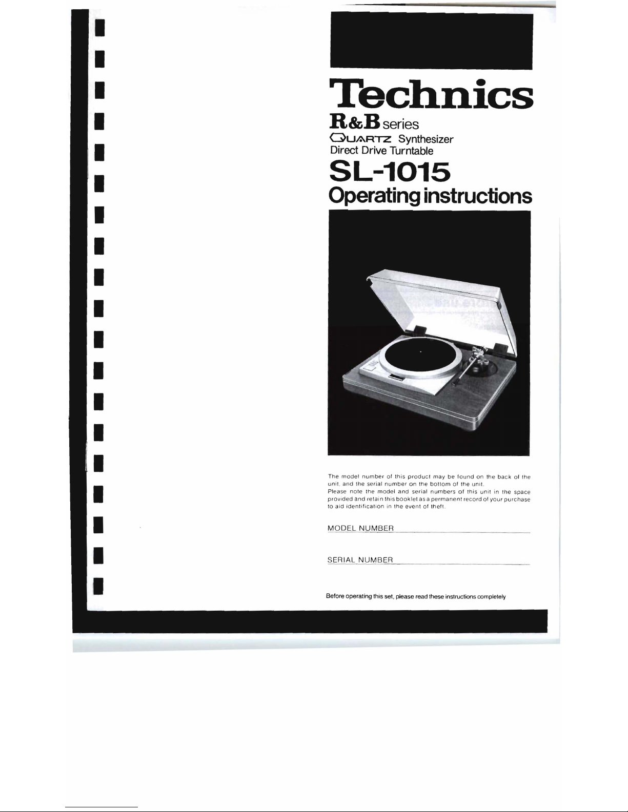
SL-1015
Operating
instructions
I
I
I
I
I
I
I
I
I
I
The
model
number
of Ihis p
roduc
l m ay
be found
on
Ihe back
of Ihe
unit.
and
Ihe
serial
number on the bott
om
of
the
unit.
Please
note the
model
and
serial
numbers
of
this
unit
in the
space
provided
and
ret
ain
this
book
let as a
permanent record
of
your
purc
hase
to
aid ident
ifi
cat
ion
in the even t of theft .
MODEL
NUMBER
SERIAL
NUMBER
Before
operating
this
set, please
read these instructions compfetefy
Page 2
We want to thank you for selecting the SL-1 015.
For optimum performance, we recommend that you
read these instructions carefully.
The SL-1015 is a high performance turntable
system which consists of a tonearm (EPA-500)
designed with compatibility of the cartridge and
tonearm
in
mind a high performance turntable base
(SH-15B 1) designed with emphasis on its damping
characteristics produced by one-piece molding of
special viscoelastic material and a quartz
synthesized system direct drive turntable (SP-15)
capable for the first time in the world of digital pitch
control at
±9.9%
through 0.1 % steps.
If
you purchase the optional tonearm unit according
to the characteristics
of
the cartridge you use, you
can upgrade your system as easily as replacing the
headshell.
Before use
Caution:
Never
connect
the
AC
power
plug
before
asse
mbly
has
been
completed
.
Attach
the dust
cover
last,
so
that
assembly
and
adjus
tments
can
be
made
most
conveniently
.
• Checklist
of
parts
Turntable
unit
(SP-15)
.
· 1
(Already
attached
to
the
turntable
base)
Turntable
platter
. . .
. . 1
Turntable
mat
.
..
. 1
Dust
cover
...
1
45
..
rpm adaptor . . . . .
..
. . .
... ' ....
. .
....
.
..
. 1
Hexagonal
wrench
.
· 1
Phono cable
· 1
Ground
wire
(GND)
..
...
.....
..
1
Turntable
base
(SH-15B1)
. . . ......
. 1
Arm
base
unit
(EPA-B500)
.
...
..
. 1
(Already
attached
to
the
turntable ba
se)
Arm
unit
(EPA-A501H)
...
..
..
.......
. 1
Screw
for
cartridge
. . .
..... . ..
.
.
...
6
Nut
for
cartridge
., ..
. . . . . ... .
...
2
Shell
weight
..
.. ...
. .
...
....
. . ... 1
Driver
.
.....
. . 2
Template.
Stylus pressure gauge
(SH
..
50P1) ...... . .
....... ...
.
1
Protector
for
stylus
tip
set
position
..
'
· 1
Gain adjustment
weight
...
1
Battery (G13)
..
. 2
Assembly and set-up
• Installation of turntable platter
1.
Place
the
turntable
platter
on the
center
spindle
.
Note:
The
rotor
is
connected
to the
underside
of the
turntab
le
platter.
(The
magnet
of
the
motor
is
attached
to the
turn-
table
platter
.)
To
maint
ain
optimum
performance
. extra
car
e s
hould
be
taken
to
prevent
adhesion of
dust
or
iron
filings
to
the
magnet
and
not
to
damage
the
magnet
by
dropping
it.
Do
not
remove
or
loosen
the
screws. Should
the
position
of
the
fixed
magnet
be
alt
ered
by
loosening
the
securing
screws,
the
rated
performance
of the unit
cannot
be
guaranteed. (See
Fig. 2.)
2.
Place
the
turntable
mat
on
the
platter.
• Attachment of cartridge
(See
Fig.
3.)
Note:
These
instructions
are
made
according
to
procedures
for
attachment
of a Technics
EPC-205C
type
cartridge
.
If
another
cartridge
is
to
be
utilized, please
attach
it in
accordance
with
the
cartridge
's
own
instruction
manual.
t .
Connect
the
lead wires
to the
cartridge. The cartridg
e
terminals
are
differentiated
by
color
. and the
leads
should
be
connected
accordingly
.
Red
.......
( R) +
(right
channel +terminal)
Green
- (R) -
(right
channel
ground
terminat)
White
.......
(L)
+
(left
channet + terminal)
Blue
.......
(L)
-
(left
channel
ground
terminal)
2.
Use
the
screws
and
nuts
provided
with
the cartridge
or
arm
unit
to
secure
the
cartridge
to the
headshell
After
this,
adjust
the
overhang.
(Refer
to the sect ion on
"Adjustment
of
overhang"
.)
Note:
To
prevent
damage
to
the
stylus
assembly
. it is
recommended
that
it be
removed
from
the
cartridge
during
installation
.
If the
cartridge
being used
has
a ligh
ter
side
value
within
the
appropriate
cartridge
weight
range
and
is to
be
used
under a heavy side
stylus
pressure
within
the
specified
stylus
pressure
range
. attach the
headshell
weight
between
the
headshell
and
cartridge
main
body
.
• Concerning the arm clamp
(See
Fig.
4.)
An
arm
clamp
is
employed
to
lock
the
rotating
section
of the
gimbal
suspension
in
place. When
instatling
the arm unit
or
when
nol
using
the
turntable, lock
the
tonearm
suspension
with
the
clamp
.
I! the
arm
clamp
is
not
locked, the
pivots will
move
and
if
the
arm
unit
has
been
installed, this
might
result
in
damage
to
the stylus
.
• Installation of the arm unit (See
Figs. 5 and
6.)
Align
the
mounting
section
of
the arm unit
with
that of the
arm base,
and
while
sliding
it in the
direction
of the
arrow,
insert
it
until
it
arrives
at
the
fixed
position
and
stops. Then
secure
it
with
the
arm-unit
lock
screw
.
Note:
eWhen
installing
or
removing
the
arm
unit,
be
sure
to
turn
the
amplifier's
volume
control
to "
0"
or
turn
off
the
amplifier's
power
before
loosening
the
arm
unit
locking
screw
.
ePlease
be
certain
to
use
the
arm
unit only
when
it
is
locked
into
position
. If
not
sufficiently
tightened, a
humming
noise
will
be
produced
.
"Warning: To prevent fire or shock hazard,
do
not expose this appliance to rain or moisture."
-5-
I
I
I
I
I
I
I
I
I
I
I
I
I
I
I
I
I
I
I
I
I
I
I
I
I
I
I
I
I
I
I
I
I
I
Page 3
I I
I I
I I
I I
I I
I I
I I
I I
I I
I I
I I
I I
I I
I I
I
I I
•
Adjustment
of
overhang
(See
Figs. 7 and
S.)
The
overhang
on this unit should be 15 mm.
Place
the
lemplate
over
the
center
spindle and align the
stylus
position
with a 15 mm line . Then
secure
the
cartridge
in that position. Refer to
"Attachment
of
cartridge"
seclion
of
the text.
Note:
ePlease
lake
care
not
to injure the
styll!s
tip.
•
Adjustment
of
arm
height
(See
Figs. 9 and
10.)
On this unit, the height of the arm can be varied up to 20
mm
by rotating the
adjustment
ring. The height is indicated
in
1
mm
increments
by the
scale
.
Note:
During
shipment of the arm unit
stylus
pressure
adjustment
ring is fixed
at
the extreme
forward
position.
Loosen
the weight
lock
screw
by rotating it
counter-
clockwise
, turn the
stylus
pressure
adjustment ring
in
a
clockwise
direction (which
makes
the stylUS pressure
lighter)
, and turn to the zero
balance
position . Then,
turning the
adjustment
ring 1 full rotation to change the
pressure
by about 0 .5
gram
, set the
stylus
pressure to
the
value
recommended
for
the cartridge
in
use .
For
cartridges
with a
heavy
weight , turn the
stylus
pressure
adjustment ring up to the
rearmost
position .
1.
Place
a
record
on the turntable and
without
rotating the
platter,
gently
lower
the
stylus
onto the
record
.
2.
Rotate the arm height
adjustment
ring until the
arm
unit
appears
parallel to the
record
.
(See
Fig, 10.)
Note:
eTake
care not to touch the arm unit at this tiule. If the
arm unit moves, this can result in
damage
to the
stylus
.
•
How
to
use
the
stylus
pressure
gauge
(SH-50P1)
•
Power
source
This
unit
is
driven by 2
silver
oxide SR44
type
batteries
.
Before
inserting
the
National
G 13
batteries
provided
,
please
read the
"Caution
when
inserting
batteries"
section
thoroughly
and
insert
them properly.
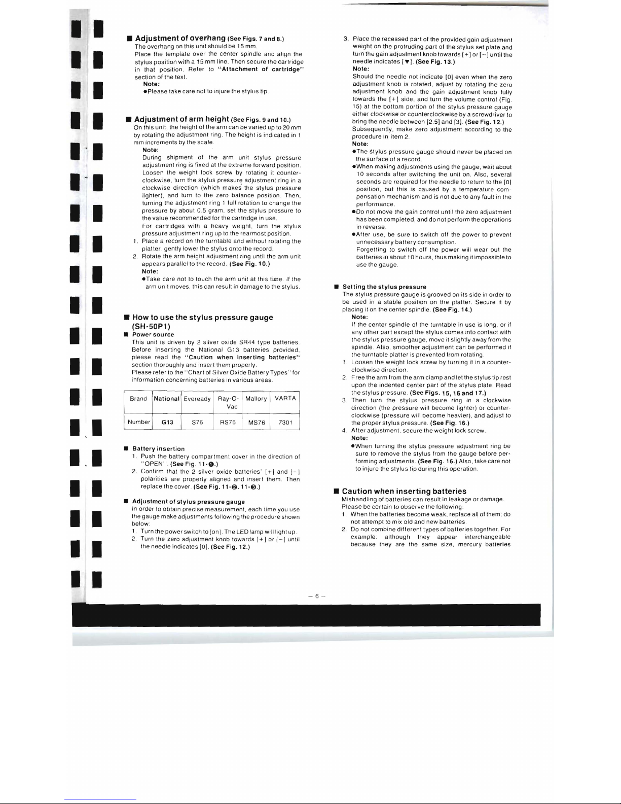
Please
refer
to the "
Chart
of Silver
Oxide
Battery
Types " for
information
concerning
batteries
in various
areas
.
Brand
National
Eveready
Ray-O-
Vac
Mallory
VARTA
Number
G13
S76 RS76
MS76
7301
•
Battery
insertion
1. Push the
battery compartment
cover
in the direction of
"
OPEN"
. (See Fig,
11-0.)
2. Confirm that the 2 silver
oxide
batteries'
1+1
and [- I
polarities
are
properly
aligned
and
insert
them Then
replace
the cover.
(See
Fig.
11-6.
"-€},)
•
Adjustment
of
stylus
pressure
gauge
In
order
to obtain
precise
measurement
. ea ch time you use
the
gauge
make
adjustments following the
procedure
shown
below
:
1. Turn the
power
switch to
[on]
. The LED lamp will light up
2.
Turn the zero adjustment knob towards
[+
I or [ - ] until
the
needle
indicates
[0].
(See
Fig.
12.)
3.
Place
the
recessed
part
of
the
provided
gain adjustment
weight
on the
protruding
part
of the
stylus
set
plate
and
turn the
gain
adjustment
knob
towards
[+]
or [- I
until
the
needle
indicates
[.)
. (See
Fig. 13.)
Note
:
Should
the needte not
indicate
[01
even when the zero
adjustment
knob
is rotated,
adjust
by rotating the zero
adjustment
knob
and the
gain
adjustment
knob
fully
towards
the
[+)
side
, and turn
the
votume controt (Fig.
15)
at
the
bottom
portion
of the
stylus
pressure
gauge
either
clockwise
or
counterclockwise
by a
screwdriver
to
bring the
needle
between
[2.5)
and
[3].
(See
Fig. 12.)
Subsequently,
make
zero
adjustment
according to the
procedure
in
item
2.
Note:
eThe
~tylus
pressure
gauge
should
never
be
placed
on
the
surface
of a
record.
eWhen
making
adjustments
using
the
gauge
, wait about
10
seconds
after
switching the
unit
on. Also, several
seconds
are
required
for the
needle
to return to the [D)
position, but
this
is
caused
by a temperature
com-
pensation
mechanism
and
is
not
due to
any
fault in the
performance
.
eDo
not
move
the gain
control
until
the zero adjustment
has
been
completed,
and
do
not
perform
the
operations
in
reverse
.
eAfter
use, be
sure
to switch
off
the
power
to prevent
unnecessary
battery
consumption.
Forgetting
to
switch
off
the
power
will wear out the
batteries
in
about
10 hours, thus making it
impossible
to
use the gauge.
•
Selling
the
stylus
pressure
The stylUS
pressure
gauge
is
grooved
on its
side
in
order
to
be
used
in a
stable
position
on the platter.
Secure
it by
placing
it on the
center
spindle. (See
Fig.
14.)
Note
:
If the
center
spindle
of the
turntable
in
use
is long , or if
any
other
part
except
the
stylus
comes
into
contact with
the
stylus
pressure
gauge,
move
it slightly away from the
spindle
. Also,
smoother
adjustment
can be
performed
if
the turntabte
platter
is
prevented
from rotating.
1.
Loosen
the weight
lock
screw
by turning it in a counter-
clockwise
direction
.
2.
Free
the
arm
from
the
arm
clamp
and
let the stylus tip
rest
upon
the
indented
center
part
of the stylUS plate Read
the
stylus
pressure. (See
Figs.
15,
16
and
17.)
3. Then turn the
stylus
pressure
ring in a clockwise
direction
(the
pressure
will bec o
me
lighter) or counter-
clockwise
(pressure
will
become
heavier), and adjust to
the
proper
stylus
pressure. (See
Fig. 16
.)
4.
After
adjustment. secure
the
weight
lock screw.
Note:
eWhen
turning the
stylus
pressure
adjustment
ring
be
sure
to
remove
the stylUS from the
gauge
before
per-
forming
adjustments.
(See
Fig.
16.) Also, take care
not
to
injure
the
stylus
tip
during
this
operation.
•
Caution
when
inserting
batteries
Mishandling
of
batteries
can
result
in
leakage
or damage .
Please
be
certain
to
observe
Ihe following:
1.
When
the
batteries
become weak, replace all of them ;
do
not
attempt
to mix old and new
batteries
.
2.
Do
not
combine
different
types
of
batteries
together. For
ex
ample
although
they
appear
interchangeable
because
they are the
same
size ,
mercury
batteries
Page 4

(MR44) and
silver
oxide
batteries
(SR44)
have
different
voltage. Also,do
not
attempt
to mix
batteries
of
different
brands. This
is not only
uneconomical
, but the unit will
not
be
able
to
display
its
performance
to the full.
3.
After
use,
be
certain
to return the
unit's
power switch to
the
[off)
position. Also, when not utilizing for
prolonged
periode,
remove
the
batte
ries from their
compartment
and store them.
4.
Remove
worn
out
batteries
and
dispose
of them
promptly.
5. Do not
attempt
to recharge
batteries,
or
short-circuit
,
break
open, heat
or
throw
into
a fire .
6. When
changing
the
batterie
s, confirm that their contact
surfaces
, as
well
as the
terminals
of the
stylus
pressure
gauge
, are clean and uniformly shaped.
At this time, be
sure
that the
batteries
are inserted
according to the
[+)
and [ - )
indications
.
• Battery life
When
the
batteries
become
worn
down
, the indicator needle
will
not
reach the [ ... ) pOint when the gain control knob is
turned to
[+
),
In
some
cases
the
LED
lamp will light,
butthe
unit
will not
be
effective
for s
tylus
pressure measurement.
Therefore, replace
the
batteries
. Refer to the section on
"Adjustment
of
stylus
pressure
gauge"
.
The
life of the
batteries
during
consecut
ive use is
about
1 0
hours
. (National
silver
oxide G13
batter
ies used at 20°C.)
Note:
Ordinarily, battery
life
becomes
shorter
when
used
at low
temperatures (below around 5°C.), Also, they do not
function well in high
humidity. Therefore
, store them
in
a
dry
place
with few
temperature
changes
.
• Adjustment of anti-skating (See
Fig,
18,)
After
adjusting the
stylus
pres
sure, turn the
anti-skat
ing
control
knob to the
same
value
as the
stylus
pressure
s
etting
,
• Adjustment of arm-lift height
(See
Figs,
19
and
20,)
The
proper
height
of
the arm
lift
(the
distance
of
the
stylus
tip
from the disc with the cueing
lever
in the [up] position) is
about
5 to 10 mm. If adjustment
becomes
necessary,
follOW
the
procedure
below:
1. Set the cueing
lever
to the [up] pOSition ,
2, Slightly loosen the
arm-lift
fixing screw, and raise or
lower
the arm
lift
. If the arm lift is raised by about 1 mm ,
the
stylus
will
be
raised by
about
ten times that amount,
or about 10 mm .
3. Then,
secure
the
arm
lift with the
arm-lift
fixing
screw
.
Connections
• Connect the AC power plug
Connect
the AC
power
plug to an AC wall socket .
• Installation of the ground wire (GND) to the
GND terminaL
(See
Figs,
21
and
22,)
Connect
the
phono
cable
provided
t·o the
phono
output jacks
on the arm base.
(The
small pin in the center is the
ground
.)
(See
Fig,
23,)
• Connect the output terminals
(See
Fig
, 24,)
Output
terminals
Amplifier
or
Receiver
l (White) •
"Channel
R (Red) •
..
Channel
GND
(Spade lug) •
~
Note:
Be sure to
connect
the
ground
terminal firmly to the
amplifier
or
receiver
. If this
connection
is not made or is
loose, a
power
source
"HUM"
will result.
-7-
• Installation of the dust cover
(See
Fig
, 25,)
Hold
the
dust
cover
at
both
sides as shown, and insert
in
the
direction
of
the arrow.
For
removing
the dust
cover
, hold the dust
cover
Open
in
a
similar
manner
and
draw
it out
in
the direction
of
the arrow
Note
:
The
tightness
of
the
dust
cover
during openi
ng
and
closing
has
been
carefully
adjusted before shipping fr
om
the
factory
. Should the dust
cover
not
move
smoothly,
however
, turn the dust cover adjusting
screw
(Fig. 25 )
clockwise
or
counterclockwise
for proper tension .
Placement
•
Place
the
unit
in a stable
and
horizontal
position
where
there
is
little
or
no
vibration
,
•
locate
the
unit
as
far
away
from
the
speakers
as
possible
and
isolate
the
unit
from
sound
radiation
from
them,
•
Do
not
place
the
unit
where
it
is
exposed
to
direct
sun,
dust,
moisture
or
heat
,
•
Keep
it
in a well
ventilated
place,
•
When a radio
is
placed
too
close
to
the
turntable
and
is
played
while
the
turntable
is
in
operation,
interference
to
AM/FM
reception
may
result
,
How to operate
1. Set the
power
switch
/pitch lock
knob
to the "on"
po
sition.
(See
Fig.
26.)
The LED
in
the speed
select
button
for 33 - 1/3 rpm , and
digital
indicators
lor
the
speed
and pitch will all light up.
(See
Fig.
27.)
Upon
setting
the
power
switch
/pitch lock
knob
to
"on"
,
the
revolutions
are
changed
over
to 33-1/3 rpm. at all
times
.
If the
record
to
be
played
is
other
than a 33-1 / 3 rpm .,
depress
the
speed
select
button
to suit the phono disc to
be
played
.
When
the
power
switch/pitch
lock knob is set to
"pitch
lock", the
pitch
control
button
and speed select button
are
locked
so as not to be
actuated
even if the buttons are
accidentally
touched
during
playing.
(See
Fig.
28.)
Therefore,
for
selecting
the
speeds
or
operating
the pitch
control, first
set
the
power
switch/ pitch lock knob to the
position
"on"
2. Place a
record
on the turntable mat.
3. Push the
start
stop
button. (See
Fig.
29.)
The
turntable
platter
will begin to rotate and reach its
constant
rotation
speed
within 0.4 second . (33-1 /3
rpm .).
4. Set the
cueing
lever
to the [up) pOSition .
(See
Fig
. 30.)
5.
Release
the lock
of
the tone arm clamp.
(See
Fig, 31.)
6.
Move
the
tonearm
over
the record to be
played
and slide
the
cueing
lever
in the "
down
" direction.
(See
Fig
. 32.)
The
tonearm
will descend slowly onto the record and
play will
begin
.
7.
After
plaY,slide the cueing lever
in
the " up " direction.
8.
Lock
the
tonearm
with
the
arm clamp.
and
slide the
cueing
lever
"down
".
9.
After
that set the
power
switch/ pich lock
knob
to
"off"
(See
Fig.
33.)
I
I
I
I
I
I
I
I
I
I
I
I I
I I
I I
I I
I I
I
I
Page 5

I I
•
How
to
suspend
play
•
Wipe
the
main
unit,
front
control
portion,
etc.
Set
the
cueing
lever
to
the
up
position
with a dry
soft
cloth
(velvet
or
the
like)
The
stylus
tip
of the
cartridge
will be
lifted
from
the
record
.
Wipe
the
dust
cover
and
turntable
base
with a
soft,dry
cloth.
Never
use
any cleaners
containing
alcohol,
benzene
or
I I
thinner,
since
luster
and
coating
of the
dust
cover
and
the
•
How
to
stop
play
turntable
base
may
be
lost.
Use
of a chemical
dust
cloth
and
Push
the
start/stop
button
.
the
like
should
also
be
avoided.
Be
sure
that
the
dust
cover
Upon
completion
of
playing, depress
the
start
stop
butlon.
is
not
exposed
to
insecticide
spray, as
cracks
or
blurs
may
I I
The
turntable
is
instantly
(0.4
second)
stopped
by
the
result.
For
removing
stubborn
finger
prints
or
grease
spots
,
double
bra
ke
system
.
be
sure
to
deta
ch
the
dust
cover
or
disconnect
the AC
power
Note
:
plug
and
use a soft
cloth
dampened
with a mild
soap
and
When
the
power
switch/pitch
lock
knob
is set to
"011"
water
solution,
and
then
wipe
it with a
dry
cloth .
I I
without
depressing
the
start/stop
button
, the
brake
mechanism
will
not
function
.
•
Lubrication
(See
Fig, 39.)
Apply 2 or 3 drops
of
oil'once
after
every
2000
hours
of
•
Pitch
control
operation
I I
(turntable
speed
fine
adjustment),
The
time
interval
is
much
longer
than
that for
conventional
The
Quartz
Synthesizer system
is
being
emp
loyed in this
type
motors
(200-500
hours)
.
unit
. A
high
degree
of
pitch
control accuracy
over a wide
Please
purchase
original
oil.
(The
part
number
is
SFWO
range (±9 .9% ) in 0.1 %
increments
can
be
obtained
with the
010
.)
I I
quartz
perfec
tly
locked
.
The
pitch
control
is
continuou
sly
variable
up
to ± 9.9% with
•
Do
not
twist
or
pull
the arm
unit's
connector
pins
or
the
accurate
and
easy
selection
.
connector
on
the
arm
base, or
otherwise
after
their
shapes
,
The
pitch
variations
which
are
clearly
indicated by
the
LED
I I
as
this
could
lead
to
misconnect
ion .
(See
Figs.
40
and
41
.)
digital
indicator
.
Take
special
caution
when installing
or
removing
the arm
The
pit
ch
control
can
be
selected
in
increments
of 0 1 %
unit.
I
which is
below
the
threshold
of
human
perception
.
(See
Fig.
34 .)
•
Do
not
depress
or
raise
the
cueing
lever. Use
it
by sliding
it
to the
right
or
left.
(See
Fig.
42.)
The
pitch
control
also
enables
you to ac
curately
and
precisely
tune mus
ical
instruments
and
by
varying
the
pitch
slighlly
, to
obtain a different
musical
note
from
the
record
.
(See
Fig. 35.)
•
Please
be
sure
to
use
the
tonearm
in a
horizontal
position
.
I I
For a half·tone
change
:
+ 5.9%
(::)
•
Do
not
push
in the
arm
lilt
when
the
fixing
screw
has
been
-5
.6%
(b)
secured . (Refer
to
Fig. 20.)
Another
feature
of
the
variable
pitch
control
over
a wi
de
I I
II
range
of ± 9.9% is that it
makes
singing
atong with a
metody
easy
for a
chorus.
or for
playing a record
for
accompaniment
only
(See
Fig. 36
.)
By
pressing
the
clear button
wh ich is
located
between
the
"+"
and
"-"
pitch
buttons,
you can
qui
ckly
return
the set
value
to
normal
playing speed . (See
Fig.
37.)
I I
For longer and safer use
of this unit
I I
I
In
order
to
receive
the
best
service
from
this unit, and for the
safest
operation,
carefully
read the
following
information
.
•
Power
source
It
is
very
dangerous
to
use
this
unit
at a voltage
which
Is
dillerent
from
the
rated
voltage.
There
is
danger
of
combustion
if
the
unit
is
connected
to a
power source
which
is
different
from
the
rated
voltage
.
Be
very
careful
concerning
this
point.
I
:1
I
Direct
current
cannot
be
used.
There
are
some
places,
such
as
ships, wh
ere
direct
current
Notes and maintenance
is
used
as
the
power
source. Before
connecting
the
unit
,
•
Be
extremely
careful
about
handling
the
confirm
the
power
source
.
turntable
platter.
(See
Fig,
38.)
Do
not
detach
the
turntable
platter
more
than
necessary
•
Connection
of
power
cord
I :1
Should
the
turntable
platter
be
removed
by
necessity
be
Be
sure
to
never
touch
the
power
cord
with
wet
hands
sure
to
first
disconnect
the
power
plug
.
because
there
is
danger
of
electric
shock. This
is true ,
of
Keep
your
hands
off
the
screws
at
the
reverse
surface of
the
course,
of
all
electric
equipment.
turntable
pia
tier
and
motor
portion
.
Do
not
pull
the
power
cord
.
I 1
Should
these
screws
be
loosened, the
rated
performance
of
Never
pull
the
power
cord
to
disconnect
it.
Always
pull
the
the
unit
can
not
be
guaranteed.
plug
only
.
-8-
Page 6

•
Location
of
unit
Choose
a place which
is
not in
direct
sunlight.
Select a place
which
will
assure
good
ventilation .
•
Never
place
heating
equipment
nearby
.
Be sure to keep stoves a
nd
other
sources
01
heat
away from
this unit,
because
heat radiated by such
equipment
may
cause
deformation
of
plastic
parts
or
damage
the cabinet,
or, at worst,
cause
a fire.
•
Especially
for
families
with
children
Take
care
that
no
small
items, such
as
metal
objects, are
put
inside
this
unit.
In addition, children should
be
especially
warned
not to
put
anything into the ventilation
holes
, such as toys or a
screw-
driver,
because
these things may
cause
an electric shock
or
result in a
malfunction
olthe
unit.
•
II
water
spills
on
the
unit.
If
water
should happen to spill on the unit, from an
overturned
vase for example, there is
danger
of
fire or
electric
shock. Disconnect
the
power
plug from the electric
outlet
immediately,
and contact
the
store from which the unit
was
purchased.
•
Reconstruction
can
cause
accidents.
Absolutely
never
try to remodel,
reconstruct
or
repair this
unit
yourself. Do not
attempt
to touch any internal
parts
because
to
do
so
may
result in an electric shock
or
other
accident.
•
Be
sure
the
power
is
off
.
After
you have finished
using
this
unit
, check once
more
to
be
sure that the
power
is
oft
. If the unit is left with the power
on for a long
period
of time, it
may
not only
be
damaged, thus
shortening
its
useful
life , but
may
also
lead to a
dangerous
accident.
Features
[Turntable/cabinet
section]
•
Quartz
synthesizer
system
that
for
the
first
time
in
the
world
has
made
it
possible
to
achieve a digital
pitch
control
of
±9,9%
in
0.1 %
increments.
•
High
torque
motor
of 3 kgcm
with
starting
time
of
0.4
second
Is
capable
of
instant
speed
change-over
.
•
Oversized
turntable
that
cuts
off
and
absorbs
external
vibrations.
•
Whole
cabinet
produced
by
one-piece
molding
with
high
grade
special
rubber. Moreover,
vibration
damping
cabinet
structure
isolates
all
main
components
such
as
turntable,
tonearm
panel,
etc.
•
Electronic
circuits
of
more
than
3,000
discrete
elements
concentrated
into
4 ICs.
•
Highly
efficient
pulse
power
supply
Circuit
is
employed
for
the
DC
power
source
.
•
Highly
accurate
rotational
characteristics
with
the
circular
detection
F.G.
•
Pitch
lock
mechanism
capable
of
locking
the
speed
selection
and
pitch
control
operation
.
•
Stable
and
positive
mechanism
that
can
stand
frequent
use
for
business
use, etc.
and a switch
section
with
point
contacts.
[Tonearm
section]
• A
"system
tonearm" that
assures
close
matching
of
tonearm
and
different
cartridge
characteristics
by
means
of
an
interchangeable
arm
unit
system
.
•
Dynamic
damping
device
reduces
low-frequency
reso-
nance
peak
by 6 dB
or
more
.
•
Gimbal-suspension
construction
•
Hardened
Titanium
tapered
pipe
specially
treated
with
nitrogen
.
•
Low
capacitance,
low
DC
resistance
phono
cable
.
•
Helicoid
arm
height
adjusting
device
permits
up
to
20
mm
variation
in
height.
•
Large-sized
heavy
zinc
(Zn)
diecast
arm
base.
•
Two-way
damped
cueing
with
stabilized
vertical
movement
.
•
Accurate
anti-skating
control
with
force
acting
in
the
axis
of
the
tonearm's
lateral
movement.
•
Gold-plated
low
resistance
connectors
.
•
Reinforced
carbon
fiber
headshell
with
lightweight,
low
resonance
design.
[Stylus
Pressure
Gauge]
•
High-sensitivity
design
with
semiconductor
strain
gauge.
A high
sensitivity
design
which
employs
the
piezo
resistance
effect
to
change
pressure
into electric resi-
stance,
this
unit
employs a pair
of
semiconductor
strain
gauges
to
compensate
for
temperature
changes,
giving
added
relia
bility
and
ex tra
sensitivity
•
Large,
easy-to-read
meter
with
direct
figure
readout.
•
LED
lamp
power
"on"
indicator.
-
9-
I
I
I
1' 1
I I
I I
I I
I I
I I
I I
I I
I I
I I
I I
.1 I
Page 7

I
I
Specifications
I
I
I
I
I
I
I
I
I
I
I
I
I
I
I
I
I
I
I
Applicable
cartridge
compliance
(dynamic,
100
Hz):
10-14
x l
0-6 cm/dyne"
Applicable
cartridge
weight:
5-
7g
Resonance
peak:
Below 6 dB
DC
resistance
of
phono
cable:
39.S
m!l
/ m
Capacitance
of
phono
cable:
41 .SpF
/m
Diameter
of
arm
base
mounting
hole:
0
62mm
"The
compliance
of
Technics
cartridge
is in
relerence
to
dynamic
compliance
.
In
cases
where
compliance
is
indicated
by
staticcom-
pliance,
convert
it
into a value
of
approximately
1/2
to
obtain
the
dynamiC
compliance
.
•
Stylus
pressure
gauge
(SH-50P1)
Type
:
Semiconductor
strain
gauge
electronic
stylus
pressure
gauge,
with " 0"
point
adjustment
and
ga
in
control
mechanism
Power
source:
DG 3
V,
Silver
oxide
ballery
(SR44
type)
x 2
Stylus
pressure
measurement
range:
05
- 3 g
Semiconductors
used
:
Semicondu
ctor
strain
gauge
. 2
Transistor
. . . 2
LED
Dimensions
:
147(W)xS2(D)x2A(H)
cm
Weight:
125 g
SpeCifications
subject
to
change
without
notice.
Weight
and
dimensions
shown
are
approximate
.
I
•
General
Power
supply:
Power
consumption:
Dimensions:
(W
x H x D)
Weight:
•
Turntable
section
(SP-1S)
I
Type:
I
Drive
method:
Motor:
Drive
control
method
:
I
Turntable
platter:
Moment
of
inertia:
Turntable
speeds:
I
Turntable
speed
fine
adjustment:
Starting
torque:
I
Build-up
time:
Braking
time:
Braking
system:
I
Speed
fluctuation
due
to
load
torque:
Speed
drift
:
Wow
and
flutter:
I
Rumble:
I
I
Pivot
construction:
Arm
pipe:
Effective
length:
Rear
stub
length
:
I
Arm
height
range
:
I
Overhang:
Lateral
tracking
error:
I
Friction:
Effective
arm
mass:
I
I
120
VAG,
50
or60
Hz,
11
W
56.6x 17.
0x46.S
cm
(22-9/32"
x6-11/16"x 18-19/64")
23 .S kg
(51 .96Ib
.)
Quartz
phase-locked
direct
drive
with
quartz
synlhesizer
pitch
control
Direct Drive
Brushless
DG
motor
Quarlz-phase-Iocked
control
Aluminum
die
-cast,
diameter
33.9
cm
(13-11/32
inches)
weighl
2.7 kg
(59Ib)
380
kg ·
cm'
(130
Ibin')
33-1/3,
4S
and
7826
rpm
Adjustable
up
to ± 9.9% in 0 1 %
increments
by
digital
indication
3
kgcm
(2.
61
Ibin)
04s.
t033-1 /3rpm
OA
s.
from 33-1 /3 rpm
Electronic
and
mechanical
braking
0%
within
2.5 kg cm
(22
Ibin
)
With
in
±0.002%
0.
008%
WRMS'
0 .02S%
WRMS
(JIS
GS521)
±003S
% peak (lEG 98A
Weighted
)
-S6
dB (lEG 98A
Unweighted)
- 78 dB (lEG
98A
Weighted)
I
'This
rating
refers to
turnlable
assembly
alone.
excluding
elfects
of record,
cartridge
or
tonearm , but
including
plalter
.
Measured
by
obtaining
signal from
built-in
frequency
generator
of
motor
assembly.
I
•
Tonearm
section
(EPA-B500,
EPA-A501 H)
Type
: Arm base with
arm
unil
interchangeability
Gimbal
suspension
type
Titanum-nitride
(TiN)
tapered pipe
250mm
Min
. 68 mm
to
max. 8S
.S mm
(from the
tonearm
fulcrum) .
Min. 42 mm -
max
. 62 mm
(from the
surlace
of the base to
the
arm
pipe)
(Helicoid
portion
.
20mm)
1Smm
+ 1°
6'
at the
inner
groove,
30
cm record
+2
°6' at the
outer
groove,
30
cm record
Under
7 mg
(lateral , vertical)
8 g
(wighout cartridge)
-10-
 Loading...