

Page 1
Service Manual
TOP NEXT
ORDER NO. AD0103076C2
Stereo tuner/ amplifier
l
SA-DV250
Colour
(S).......................Silver Type
Areas
EB.......................Great Britain.
EG.......................Europe.
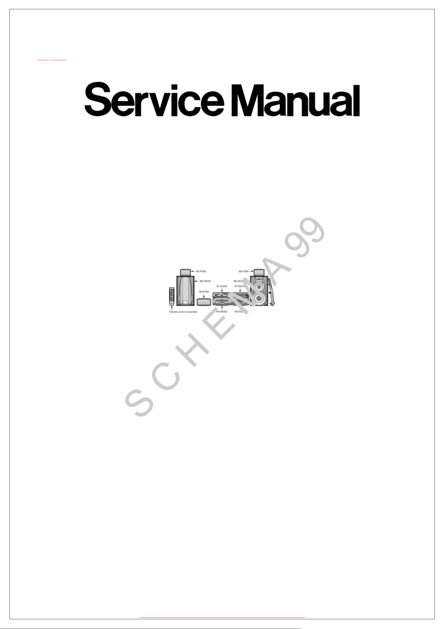
System: SC-DV250
Because of unique interconnecting cables, when a
compact requires service, send or bring in the entire
system.
Specification
•Amplifier Section (Low frequency side)
Power output
DIN 100Hz, THD 1%, 8Ω both channels driven:
RMS 100Hz, THD 10%, 8Ω both channels driven:
•Amplifier Section (High frequency side)
Power output
DIN 1kHz, THD 1%, 6Ω both channels driven:
RMS 1kHz, THD 10%, 6Ω both channels driven:
Power output (prologic mode)
DIN (front: high frequency) 1kHz, THD 1%, 6Ω both channels driven:
(front: low frequency) 100Hz, THD 1%, 8Ω both channels driven:
(surround) 1kHz, THD 1%, 8Ω both channels driven:
(center) 1kHz, THD 1%, 8Ω: 60W
RMS (front: high frequency) 1kHz, THD 10%, 6Ω both channels driven:
(front: low frequency) 100Hz, THD 10%, 8Ω both channels driven:
(surround) 1kHz, THD 10%, 8Ω both channels driven:
(center) 1kHz, THD 10%, 8Ω: 80W
• Total harmonic distorition
Rated power at 1kHz/ 6Ω: 1%
Half power at 1kHz/ 6Ω: 0.1%
• Load impedance
(high frequency): 6Ω
Front
(low frequency): 8Ω
Surround: 8Ω
Center: 8Ω
• FM tuner section
Frequency range: 87.50-108.00MHz
Sensitivity (S/N 26dB): 1.5μV
S/N: MONO 70dB
Antenna terminals: 75Ω (unbalance)
• AM tuner section
2x45W
2x65W
2x25W
2x35W
2x25W
2x45W
2x30W
2x35W
2x65W
2x40W
(0.05MHz steps)
(75dB, IHF)
http://servis-manual.com/
Page 2
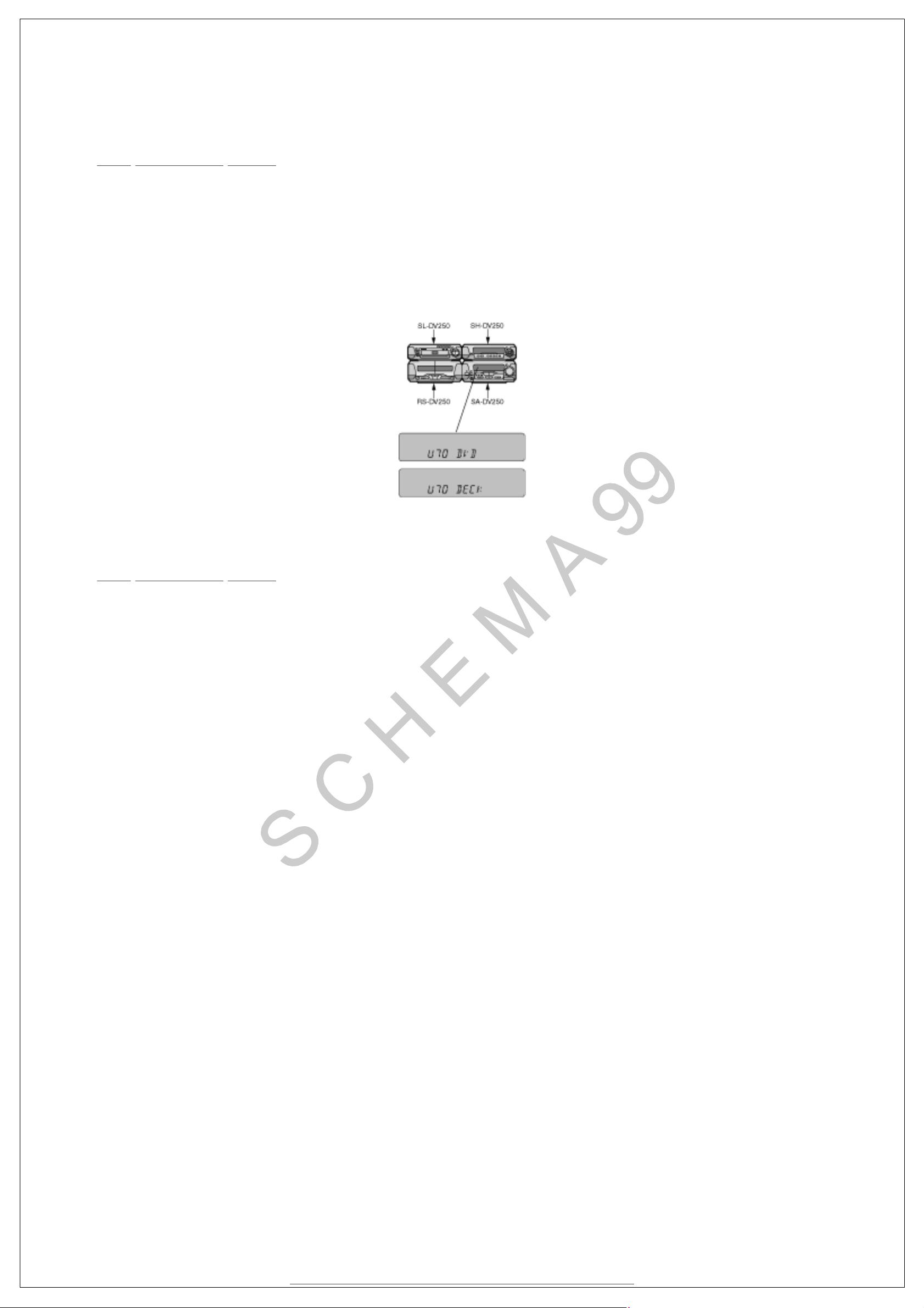
7.1 To display the malfunction code
TOP PREVIOUS NEXT
U70 DVD:
U70 DECK: tuner/amplifier when a malfunction occurs. Refer to Fig. 7-1.
F61: Automatically displays on the tuner/amplifier when a malfunction occurs. Refer to Fig. 7-1.
Automatically displays on the
Fig. 7-1
@
TOP PREVIOUS NEXT
http://servis-manual.com/
Page 3
7.2 To return to the normal display
TOP PREVIOUS NEXT
1. For U70 DVD/U70 DECK
¡
Press an any operation button on the tuner/amplifier.
¡ To re-display the code, switch the power off (POWER STANDBY button), and then
switch power back on again.
2. For F61
¡ If F61 is displayed, the power will automatically be switched off and the standby
indicator will light up.
¡
F61 will be displayed for 3 seconds, and then the clock will be displayed.
¡ To re-display the code, switch the power on. F61 will be re-displayed, and then after 3
seconds the clock will be displayed and the power will automatically switch off.
@
TOP PREVIOUS NEXT
http://servis-manual.com/
Page 4
7.3.1 U70 DVD, U70 DECK/(displayed
automatically)
TOP PREVIOUS NEXT
l
Problem or condition
A bus-line communications error has occurred as a result of the flat cables being inserted
incorrectly, thus preventing the system from operating.
¡
If U70 is displayed on the tuner/amplifier, the Cassette deck or DVD Changer cannot be
operated by remote control.
l
Correction Procedure
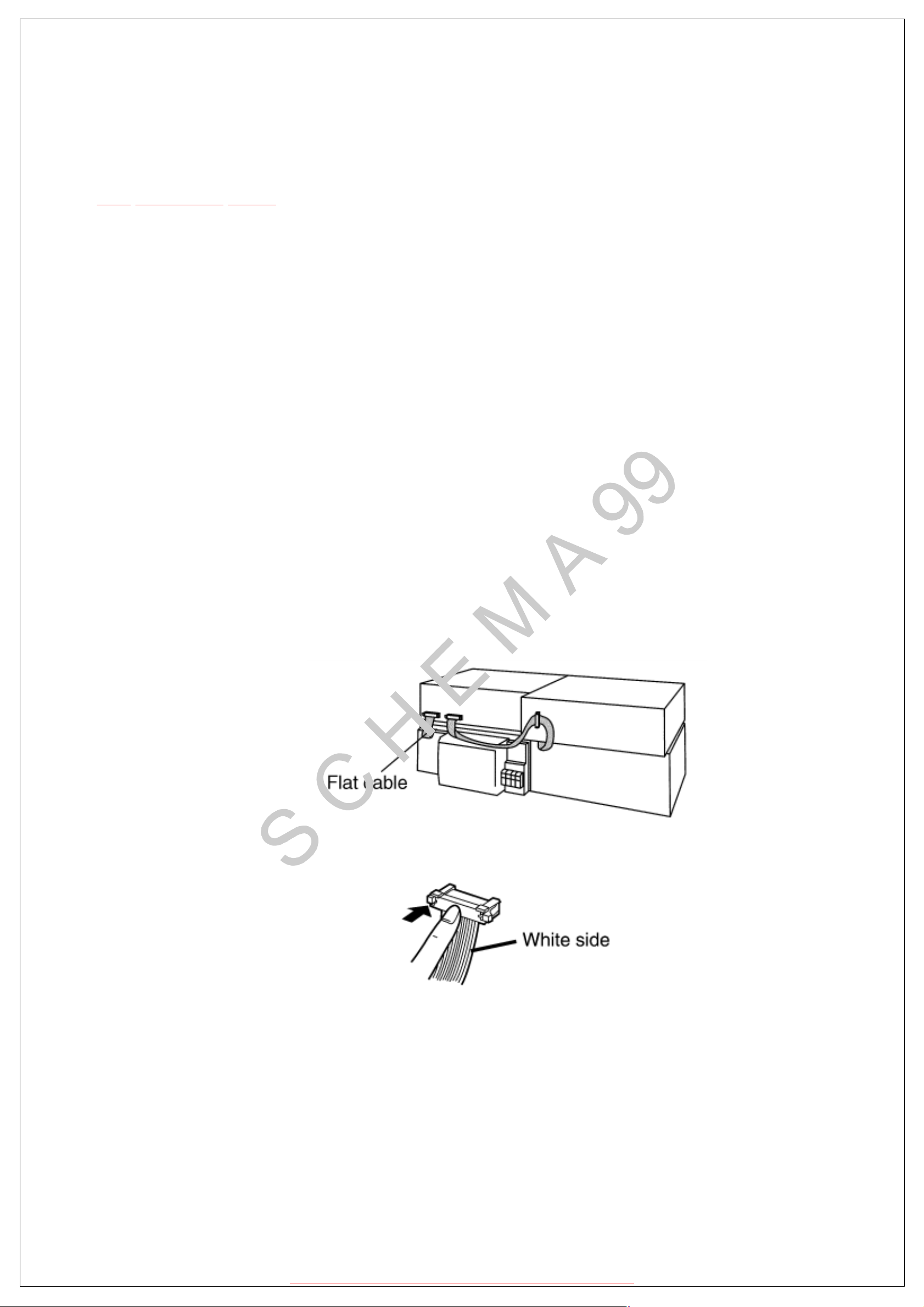
1.To check for correct insertion of the flat cables.
n Insert each connectors until you hear a click.
n
Insert the flat cables at the back of the unit in the order indicated. Refer to Fig. 8-
2.
Make sure the white side of the cables is on your right side. Refer to Fig. 8-3.
Fig. 7-2.
Fig. 7-3.
2.Breakage of the flat cables. (Check and replace.)
3.If the problem is not corrected by items 1 and 2 above, this indicates a faulty IC.
SA-DV250:
IC901 (C2BBFD000317)
http://servis-manual.com/
Page 5

SL-DV250:
IC401 (M38504E6227F)
RS-DV250:
IC701 (M38503M2406F)
Check these ICs and replace.
@
TOP PREVIOUS NEXT
http://servis-manual.com/
Page 6
7.3.2 F61
TOP PREVIOUS NEXT
l
Problem or condition
When the power switch is switched on, it automatically switches back off, making it
impossible to switch power on.
l
Correction procedure
Faulty Tuner/Amplifier (SA-DV250) output IC (IC601).
(When a DC voltage is applied to speaker terminals.)
@
TOP PREVIOUS NEXT
http://servis-manual.com/
Page 7

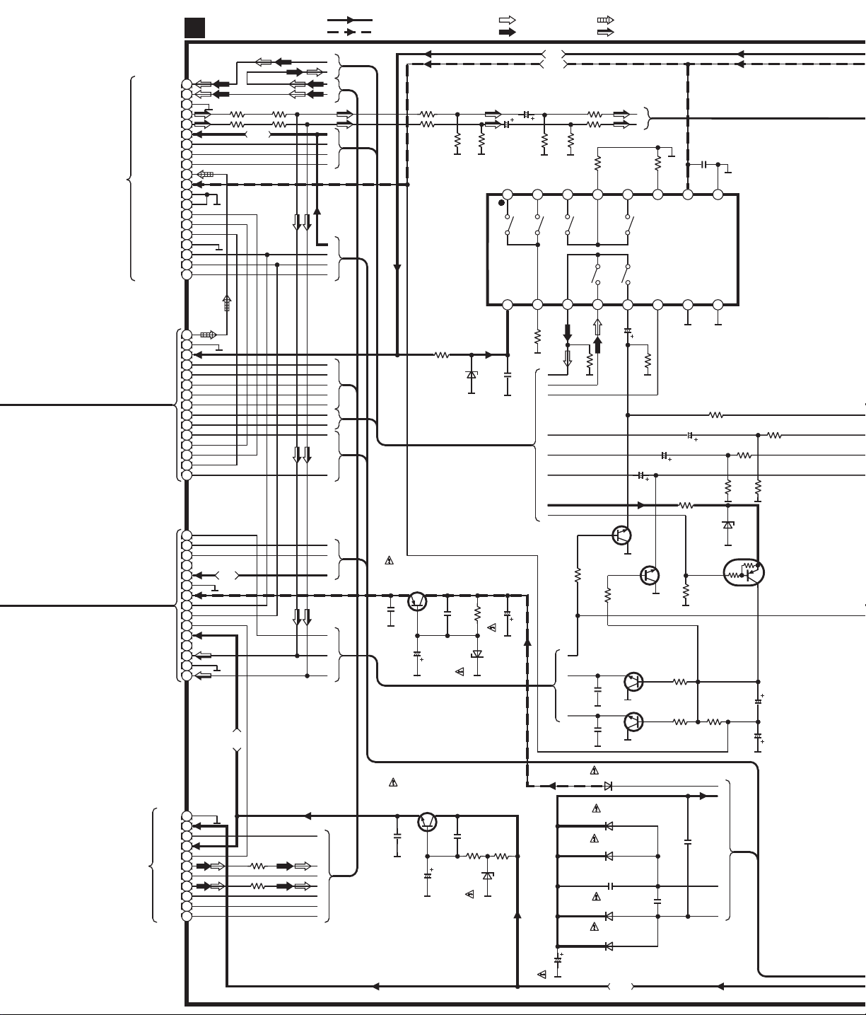
SCHEMATIC DIAGRAM-1
OPERATION CIRCUIT
A
NOTE:
The number which noted at the connectors on the schematic diagram as
"SCHEMATICDIAGRAM-1" or "SCHEMATIC DIAGRAM-2"
indicates the schematic diagram serial number located on the left corner in the schematic diagram.
:AUDIO SIGNAL LINE
R997
D973
C921
150
MA4030MTA
1000P
R996
150
FL901 (A2BB00000084)
C922
35V33
1 6 8 10 11 12 13 14 15 16 17 18 19 20 21 22 23 24 25 26 27 28 29 30 31 32 33 34 35 36 37 38 39 40 41 42 43 44 45 46 47 48 49 50 53 542 5 7 9
C920
25V22
C928
25V22
)
S908
INPUT SELECTOR
(
R912
4.7K
)
S913
(DIGITAL
S.WOOFER
S912
(TUNER/ BAND)
R907
3.3K
R911
3.3K
S907
S911
)
SET
(
)
TUNING,
(
R906
2.2K
R910
2.2K
S906
S910
)
TUNING MODE
(
)
(TUNING,
R905
1.8K
R909
1.8K
S905
)
FM AUTO/MONO
(
R904
1.5K
R916
1.5K
S904
)
PLAY/ REC
(
FL DISPLAY
R903
1.2K
)
S903
DEMO
(-
R915
1.2K
ABCDEFGHI JKLMNOPQRSTU
ABCDEFGHIJKLMNOPQRSTUVWXYZ
R922
R921
10K
10K
R925
1K
R924
1K
C908
C907
470P
470P
R9021KR901
R9141KR913
820
)
S902
CLOCK/ TIMER
(
820
)
PTY
S915
(
(RDS DISP MODE)
S901
S914
)
/
(
)
PS
(
R944
2.2K
X
W
C919
C927
25V22
25V22
JK903
PHONES
3.5mm STEREO
W905
2
3
6
4
5
7
1
0.1
C923
C396
0.047
C395
0.047
S
T
D974
MA165TA
C904
0.01
C924
V
0.1
Page 8

SCHEMATIC DIAGRAM-2
-
30.1V
-
30.1V
-
R990
100K
D306
29.3V
-
29.3V
-
29.3V
-
26.3V
-
20.5V
-
29.3V
-
29.3V
-
29.3V
-
23.5V
-
20.5V
-
23.4V
-
23.4V
-
23.7V
-
20.7V
-
29.6V
-
29.6V
-
29.6V
-
23.7V
-
26.6V
-
26.5V
5.1V
-
29.5V
-
29.5V
-
26.5V
-
17.2V
-
5.3V
-
10.3V
0.4V
0V
1.5K
R939
( )
SELS5223C
A
B
C
D
E
F
G
H
I
J
K
L
M
N
O
P
Q
R
S
T
U
V
W
X
Y
Z
D931
MA165TA
D933 MA165TA
100K
R993
C916
6.3V100
: POSITIVE VOLTAGE LINE : NEGATIVEVOLTAGELINE
A
B
C
ABCDEFGHI JKLMNOPQRST UVWX
-
VP
51
P13
52
P14
53
P15
54
P16
55
P17
56
P18
57
P19
58
P20
59
P21
60
P22
61
P23
62
P24
63
P25
64
P26
65
P27
66
P28
67
P29
68
P30
69
P31
70
P32
71
V
72
P33
73
P34
74
P35
75
P36
76
P37
77
P38
78
REGIN0
79
REGIN1
80
R986
)
D954
PLAY/ REC
SELS5923C
(
5.1V
23.4V-20.5V-26.3V-26.3V
-
P12
DD4
STAND-BY
81 82 83 84 85 86 87 88 89 90 91 92 93 94 95 96 97 98 99
1.5K
D951
LNJ301MPUJAD
P9
P11
P10
FM / AM
T 5.5ms.
F=32.7kHz
2V/2ms.DIV.
TIMER
S.W.LED
LOUNGE
0V
0V0V0V
220
R995
)
R994 100K
S.WOOFER
(DIGITAL
R999
23.4V-20.5V-26.2V
-
5.1V
P8P7P6P5P4P3P2
DD3
V
IC901
C2BBFD000317
SYSTEM CONTROL/
FL DRIVE
4V
0V
-
30V
FM / AM
2V
P-P
T
10ms.
CHORUS
MUTENCPOWER
0V
0V
4.8V
100K
R960 1.5K
R958 1K
R959 47
26.2V-26.2V-26.1V-26.3V-23.5V-23.5V
29.2V
-
-
T 5.5ms.
FM / AM
F=6MHz
FM / AM
F=32.7kHz
F=32.7kHz
5V
0V
2V/2ms.DIV.
5V
0V
DD2
Vss2
V
MUTE2NCMUTE3
0V
5.1V
5.1V
C905
1000P
2.7K
R969
27.5V-25.5V
23.5V
-
-
P1
1G2G3G4G5G6G7G
FM / AM
5.2V
P-P
FM / AM
3.3V
P-P
1.4V
FM / AM
F=6MHz
SHCS
1.9V
R936
SHDO
1.9V
R935 100
100
5.2V
P-P
SHDI
SHCK
3.3V
R934 100
-
4V
0V
5.1V
R988 1K
25.6V-27.5V
-
3132333435363738394041424344454647484950
REMOCON
30V
RDS DATA
4.2V
P-P
KEY KARAOKE
SEL/ TUNER
SEL TUNER
5V
ST/ AV.6CH
0V
LC72 DI/ ST
E DET
CR TIMER
100
0V
R987 1K
R937 10K
RDS CLK
HP SW
MIC DET
VR JOGA
VR JOGB
NC(GND)
SH REQ
KEY TU
DD1
V
XC OUT
XC IN
Vss
X OUT
XIN
RESET
AC IN
LC72 CK
LC72 CE
LC72 DO
CHECK
SD
C901
8G
6.3V100
30
29
28
27
26
25
24
23
22
21
20
19
18
17
16
15
14
13
12
11
10
9
8
7
6
5
4
3
2
1
R926
2.2K
R919
15K
R991
47K
-
25.6V
5.1V
2.6V
2.6V
0.6V
5.1V
0V
0V
1.4V
5.1V
5.1V
5.1V
2.3V
2.3V
2.7V
1.6V
5V
2.2V
0V
5.1V
5.1V
4.6V
0V
0V
2.5V
R976
100K
R918 10K
C903
R953 100
D905 1SS291TA
R928 47K
L902 1 H
0.01
R954
100K
C912
1SS291TA
R949
R950
0.1
C911
C926
D902
4.7K
100
18P
1000P
5V
A
B
C
D
E
R952
10M
X902
(32.7kHz)
5.1V
Q901
UN4212TA
RESET
C925
R9561KR957
C915
R940
R929 1K
R930 1K
R932 1K
R931 1K
X901
(6MHz)
1
3
330K
R951
20P
C910
0V
1000P
0.01
1K
D901
1SS291TA
C914
D904
1K
2
50V2.2
MA165TA
L901
10 H
C902
10V1000
U
J
H
G
A
B
D
C
EFIKLMNO Q
Page 9

SCHEMATIC DIAGRAM-3
OPERATION CIRCUIT
A
: POSITIVE VOLTAGE LINE : NEGATIVEVOLTAGELINE
:AUDIO SIGNAL LINE
5.1V
EVQVBXFK124B
(VOLUME)
COM
C151
16V10
C158
6.3V47
560P
C154
47P
C157
VR901
22K
R962
BA
1 2 3
100
R945
IC151
C1BB00000527
RDS SIGNAL
DEMODULATOR
2.5V
VREF
1
2.5V
HPX IN
2
5.1V
V
DDA
3
VssA
4
2.5V
FL OUT
5
2.5V
CIN
6
TEST
7
X OUT
8 9
X151
0.01
C917
22K
R961
100
R943
DEA
IDR
16
2.6V
RDCL
15
2.6V
RDDA
14
0V
RST
13
1K
DDB
XIN
R157
12
5.1V
11
10
2.5V2.7V
47P
C156
MODE
V
VssB
C918
6.3V100
C909
1000P
R946
R151
R153
C155
1K
1K
100K
1000P
1K
R152
100K
R154
C153
1000P
L151
100 H
BC
Z901
B3RAD0000028
(REMOTE SENSOR)
3
2
1
C159
C160
6.3V47
1000P
L152
H
100
R942
2.2K
Q902
UN411FTA
MUTING CONT.
3.3V
0V
M
A
B
C
D
E
F
G
H
I
J
K
L
MA165TA
MA165TA
U
N
O
Q
S
T
3.3V
D906
D907
6V
R941
1K
R974
1K
C931
16V10
N
R975
D961
ABC
7.6V
W902B
15
14
13
12
11
10
9
8
7
6
5
4
3
2
1
-30.1V
W901B
15
14
13
12
R965
R966
3.9K
3.9K
22K
MA4075MTA
H
L153
1
120
R155
11
10
9
8
7
6
5
4
3
2
1
C152
330P
R158
1K
D151
MA4051MTA
Page 10
SCHEMATIC DIAGRAM-4
MAIN CIRCUIT
B
A.GND
Lch IN
Rch IN
+B(10V)
SUR L
SUR R
S.W
MIC
10V)
V.GND
D.GND
CLK
DATA
CT GND
SH FL1
SH FL2
SYNC
W501
1
2
3
4
R512 47R510 47
5
6
7
8
9
10
11
12
13
14
15
16
17
18
19
20
W902A
15
14
13
12
11
10
9
8
7
6
5
4
3
2
1
W901A
15
14
13
12
11
10
9
8
7
6
5
4
3
2
1
To
SOUND
PROCESSOR
(SH-DV250)
TUNER Lch/C
TUNER Rch
-B(-
CS/ REQ
R51147R509
10.4V
6V
7.2V
: POSITIVE VOLTAGE LINE
: NEGATIVEVOLTAGELINE
H
G
A
47
B
A
B
C
D
B
E
F
G
C
D
E
F
G
E
F
J
K
L
M
I
A
B
C
Q707
2SB1417PQTA
REGULATOR
-
30.1V
C708
0.047
-
30.7V
C706
35V10
R597
2.2K
R598
2.2K
-
R211
37.3V
270
C707
R563
0.047
2.7K
D201
MA4056MTA
R708
D721
R564
4.7K
MA4300MTA
: FM SIGNAL LINE
: AM SIGNAL LINE
7.6V
-
10.4V
C659
16V10
C660
16V10
2.7K
1 2 3 4 5 6 7 8
16
5.7V 0V 0V 0V 0V 0V
0.1
C201
Q605,606
2SD2144STA
MUTING
100
C737
R205
R615
15
100K
4.7K
H
G
F
C
B
D
A
E
R614
A
B
C
4.7K
14
R683
1K
:MIC SIGNAL LINE
:AUDIO SIGNAL LINE
R631
R202
3.9K
R632
3.9K
R203
100K
100K
13
0.7V
A
B
R204
0V 0V-10.4V
IC201
BU4053BCFE2
SIGNAL SELECTOR
X0X1VDD
12 11 10 9
C601
16V10
4.7K
R617
C602
16V10
0V
Q605
-
10V
Q606
1K
R684
Q609,610
2SD2144STA
MUTING
Q609
0V
-
0.01
C509
Q610
0V
-
0.01
C510
100K
INHZ0Z1Y1 Y0
16V10
10V
10V
A
C655
0V
R696
R693
1K
R692
1K
16V10
R695
470
47K
C202
0.1
Vss
B
C656
Q612
UN411FTA
MUTING CONT.
R603
3.3K
4.9V
R694
22K
G
C
R605
D611
4.7K
MA4051MTA
R687
1.5K
R606
C664
C725
4.7K
5.1V
-
16V10
16V47
R688
1.5K
10.2V
ToTUNER UINT
on SCHEMATIC
DIAGRAM-10
T.GND
+B(1)
+B(2)
DET
Rch IN
Lch IN
D705
C715
6800
RL1N4003N02
D718
RL1N4003N02
D717
RL1N4003N02
C731
1000P
D720
RL1N4003N02
D719
RL1N4003N02
14.7V
C741
H
A
C714
1000P
D
0.1
C
Q723
2SC3940AQSTA
CP101
1
2
3
SD
4
5
6
7
CE
8
9
DI
10
DO
11
CL
R230 1K
R229 1K
G
B
F
A
E
D
C
REGULATOR
C735
0.047
7.8V
C740
16V10
14.7V7.2V
R763
R764
C733
0.047
330
D737
4.7K
MA4082LTA
Page 11

SCHEMATIC DIAGRAM-5
IC601
MA700ATA
RSN311W64B
POWER AMP
D756
D757
MA700ATA
: POSITIVE VOLTAGE LINE
: NEGATIVEVOLTAGELINE :AUDIO SIGNAL LINE
7.6V
-
10.4V
123456789101112131415181920212223242526 1617
-
59.5V
-
29.3V
-
51.4V
0V0V0V0V
0V0V54.1V
29.7V
-
0.2V
29.4V
-
0V0V0V0V
0V28.9V
0V0V59.5V
C648
1000P
B
A
R602
3.3K
0V
Q607
0V
0.7V
Q608
C603 470P
R601
3.3K
4.7K
R618
R685
1K
0.7V
R686
1K
Q607, 608
2SD2144STA
MUTING
C604 470P
R604
L
K
3.3K
C607 470P
C608 470P
C617
0.01
C649 1000P
C650 1000P
R691
68
C605 1000P
C606 1000P
R612 56K
C610 56P
R611 56K
C609 56P
R610 150K
C612 15P
R609 56K
C611 39P
R608 56K
C614 47P
R607 56K
C613 47P
22K
R628
R648
120
R647
270
C622
10V100
R572
R627
15K
N
470K
C616
50V0.47
R620
120K
R619 120K
R622 120K
R621 150K
R624 150K
R623
120K
0V
Q601 Q602
Q601,602
2SC5398RSTA
PROTECTOR
10K
D558
MA165TA
Q503
2SC5398RSTA
SWITCHING
R544
SB360L6508
R635
2.2K
0.1
C619
D601
SB360L6508
68K
R638
0.1
C709
D659
D658
MA165TA
D657
MA165TA
MA165TA
D602
5.1V5.1V
0V
0V
0V
D607
1SS291TA
15K
R637
M
G
0.01
C705
AB C
Q708
UN4211TA
SWITCHING
(POWER)
2.1V
C618
0.01
R738
3.9K
Q709
2SD2144STA
SWITCHING
(POWER)
0V 0V
10K
R776
0.7V
R739
47K
D754
RL1N4003N02
D755
RL1N4003N02
14.7V
1N5402BM21
4700
C704
4700
C702
D704
D753
RL1N4003N02
D761
RL1N4003N02
D702
1N5402BM21
1N5402BM21
4700
C703
4700
C701
D752
1N5402BM21
D703
C761
D751
0.1
D701
1N5402BM21
1N5402BM21
220
R761
G
F
E
D
Page 12

SCHEMATIC DIAGRAM-6
MAIN CIRCUIT
B
Q556
2SC5398RSTA
SWITCHING
0V
R569
10K
0.5V
D554
FAN ON:0V4.7V
MA165TA
R557
D551
R547
10K
MA165TA
18K
C552
0.01
0.3V
Q551
2SA1995RSTA
SIGNAL LEVEL DET.
C371
6.3V100
C551
50V2.2
18K
R546
-
10.4V
R570
2.2M
R559
4.7K
: POSITIVE VOLTAGE LINE
: NEGATIVEVOLTAGELINE
7.6V
100K
R560
7.6V
-
10.4V
-
10.4V
R591
Q555
4.7K
2SD2144STA
SIGNAL LEVEL DET.
100K
R556
18K
47K
R551
R552
R555
22K
D583
RL1N4003N02
D582
RL1N4003N02
MA165TA
:AUDIO SIGNAL LINE
FAN ON:0V
0.5V
Q557
2SA1995RSTA
MOTOR DRIVE
R558
2.2K
C554
D552
10V220
R561
100K
R566
68K
R568
100
0V
Q554
2SA1995RSTA
SIGNAL LEVEL DET.
D555
MA4100MTA
C550
A
D553
0.01
MA700TA
7.6V
7V
0V
Q553
2SD2144STA
MOTOR DRIVE
C559
0.01
16V10
0V
C556
N
7.6V
6.8V
FAN ON:1.6V
JK551
C555
R567
FAN MOTOR
M
1
N
16V10
22
2
R719
3.3K
29.2V
0.047
R724
C718
D581
3.9K
16V100
RL1N4003N02
R722
2.2
C710
0.047
Q701
2SD2374PQAU
REGULATOR
15.2V
C717
16V33
29.2V14.7V
R725
C719
0.047
10
D723
5.6K
R723
MA4150HTA
B
C
D
E
F
R721
R720
G
4.7
1032 4 5 6 7 8 9
1032 4 5 6 7 8 9
3.9K
POWER SUPPLYCIRCUIT
C
Q702
2SB1548PQAU
REGULATOR
-
30.1V
-
10.4V
-
11V
C722
16V100
-
0.6V
Q705
2SA1995RSTA
STABILIZER
C720
-
11V
R796
2.2
R797
2.2
C724
0.047
AB
C639
1000P
C640
1000P
C641
1000P
C642
1000P
C732
0.022
C647
1000P
E601
E602
7.6V
Q704
8.1V
Q703
C721
10V100
30.1V7.6V
Q703,704
2SD2137PQTA
REGULATOR
30.1V
8.1V
C723
0.047
14.7V
-
10.4V
10.4V
D738
MA165TA
R729
220
Q711,712
2SB1548PQAU
REGULATOR
R768
100
D730
MA4091HTA
D758
3.9K
R727
D725
MA4082LTA
10.4V 14.1V
Q712
D739
MA165TA
C734
50V3.3
MA165TA
13.6V
10.2V
R769
27
10.4V
CN781
W701B
Q711
9.6V
R765
R767
27
1
1
1K
R754
R749
0.47
R753
14.1V
13.6V
13.6V
Q725
2SC5398RSTA
STABILIZER
220
0.47
Page 13

SCHEMATIC DIAGRAM-7
: POSITIVE VOLTAGE LINE
: NEGATIVEVOLTAGELINE :AUDIO SIGNAL LINE
L605
C635
C637
C636
C632
IJ
0.047
0.047
0.047
0.047
CP601
CP602
JK601
JK602
GND
1
GND
2
C OUT
3
C OUT
4
GND
5
GND
6
GND
7
GND
8
SUR L OUT
9
SUR L OUT
10
SUR R OUT
11
SUR R OUT
12
ECO
1
SH SYNC
2
SA SYNC
3
D.GND
4
BU5V
5
RS13V
6
+B
7
NC
8
HF(6 )
LF(8
HF(6 )
LF(8
R649
B
C
A
D
F
E
G
A
B
C
10
L602
R640
10
L606
R650
10
L601
R639
10
R652
C626
C628
R641
C621
C631
10
R651
0.1
C627
0.1
C629
10
0.1
0.1
10
R642
0.1
C620
0.1
C630
10
0.1
0.1
SPEAKERS
Lch
)
Rch
)
D
To AC IN CIRCUIT(CN601)
on SCHEMATICDIAGRAM-8
D
To AC IN CIRCUIT(CN602)
on SCHEMATICDIAGRAM-8
W722A
W721A
S1
1
S2
2
S3
3
S4
4
S1
1
S2
2
S3
3
S4
4
AC1
5
CT
6
AC2
7
S7
8
FL2
9
FL1
10
D
E
F
G
C
D
H
F
E
E
To POWER
TRANSFORMER(A)
CIRCUIT(W722B)
on SCHEMATIC
DIAGRAM-8
E
To POWER
TRANSFORMER(A)
CIRCUIT(W721B)
on SCHEMATIC
DIAGRAM-8
Page 14

SCHEMATIC DIAGRAM-8
B
To MAIN CIRCUIT(CP601)
on SCHEMATICDIAGRAM-7
SUR L IN
SUR L IN
SUR R IN
SUR R IN
SH SYNC
B
To MAIN CIRCUIT(CP602)
on SCHEMATICDIAGRAM
SA SYNC
-
7
GND
GND
C OUT
C OUT
GND
GND
GND
GND
ECO
D.GND
BU5V
RS13V
+B
NC
AC IN CIRCUIT
D
CN601
1
2
3
4
5
6
7
8
9
10
11
12
CN602
1
R712 2.2K
2
3
4
5
6
7
8
RL1N4003N02
A
B
C
Q726
2SC3940AQSTA
REGULATOR
0.01
C754
6.7V
C759
10V47
D711
10.7V6V
R773
18
C758
D747
R795
0.01
MA4068LTA
R774
3.9K
18
D745
MA4051MTA
RL1N4003N02
D746
R777
1K
R772
22K
A
C
B
D740
MA165TA
Q791
2.2K
R771
2SD2144STA
RELAYDRIVE
: POSITIVE VOLTAGELINE
: NEGATIVE VOLTAGE LINE
JK603
CENTER(8 )
L604
R644
L603
R643
10
10
R645
0.1
C633
0.1
C625
0V
0.7V
C651
0.047
C652
1000P
10
10
C646
0.047
C644
C645
0.047
C643
1000P
1000P
R646
C624
C634
0.1
0.1
Rch
SURROUND(8
Lch
SPEAKERS
)
B
To MAIN
CIRCUIT
(W722A) on
SCHEMATIC
DIAGRAM-7
B
To MAIN
CIRCUIT
(W721A) on
SCHEMATIC
DIAGRAM-7
AC1
AC2
FL2
FL1
POWER TRANSFORMER
E
(A) CIRCUIT
W722B
S1
1
S2
2
S3
3
S4
4
S1
1
S2
2
S3
3
S4
4
5
CT
6
7
S7
8
9
10
W721B
A
B
C
D
1000
C755
R791
RSFMB50KT-L
R792
RSFMB50KT-L
R793
A
B
C
D
R798
2.2
47K
R794
D743
D741
RL1N4003N02
RL1N4003N02
C753
0.01
D742
D744
RL1N4003N02
RL1N4003N02
D500
MA165TA
6V
1
CN701
CN702
AC
29.2V
AC22.6V
AC22.6V
AC11.7V
AC11.7V
AC4.7V
CN703
CN704
CN705
CN706
CN707
CN708
CN709
CN710
AC9.4V
RL702
3 1
T701
T702
24
F
F1 T2A
Z701
C791
1000P
POWER TRANSFORMER
(B) CIRCUIT
CN711 W1
CN712
CN713
L701
JK701
AC IN
230-240V 50Hz [EB]
230V 50Hz [EG]
W2/W3
W1
For [EG] area.
W3
W2
For [EB] area.
Page 15

SCHEMATIC DIAGRAM-9
FM ANT
(75
AM ANT
EXT
LOOP
Z101 TUNER UNIT(RAN0005EM-2)
100K
0~5P
22P 15P
)
0.47 H
10K
0.47 H
5.6K
0.01
5P ~ 12P
33K
22P0.022
2.7K47P
1000P
2SK360
RF AMP
5P
10P ~ 33P
0.047
27P
100K
7.2MHz
100K
6 ~ 220
1P ~ 5P
330P ~
580P
27P~ 33P
0.022
2P
2SK360
FM OSC
100K
5 ~12P
10K
:POSITIVE VOLTAGE LINE
6P ~ 10P
33K
100
8P
10K 10K
22
4.7
560
1K
33K
2SC2413
BUFFER AMP
27P
680 ~
A
C
B
D
DZS5.1B
2.2K
:FM SIGNAL LINE
:FM OSC SIGNAL LINE
2SC2059
1 H
1000P
330
100
FM MIXER
680
820K ~ 2.2M
22K~100K
390
220
27K
100P0.01
4P
27P
1P ~ 5P
2P
220
0.022
5P
18P
H
0.58
1000P
1000P
:AM SIGNAL LINE
:AM OSC SIGNAL LINE
10K
0.022
0 ~ 220
150
0.01
0.022
A
B
C
D
100
100
20 19 18 17 16 15 14 13 12 11
Vss
X OUT
XIN
CE
1 2 3 4 5 6 7 8 9 10
3.3K
10K
1K
ABCD
AIN
A OUT
CL
DI
1K
1K
DD
PD
V
LC72131M
PLL FREQUENCY
SYNTHESIZER
DO
B01
470
FM IN
AM IN
B02
B03
1K
I02
B04
I01 IF IN
E
F
10K
Page 16

SCHEMATIC DIAGRAM-10
:POSITIVE VOLTAGE LINE :FM SIGNAL LINE :AM SIGNAL LINE :AM OSC SIGNAL LINE
10K
0.01
270 ~ 680
LA1833MN
FM/AM IF AMP,
1K ~ 10K
DET/AM OSC,MIX/FM MPX
3.3
1000P
24 23 22 21 20 19 18 17 16 15 14 13
AM OSC
AM OSC OUT
A
D
B
C
AFC
1000P
270K ~ 680K
47K
AM RF IN
2SC2413
FM IF AMP
4.7
AGC
330
0.01 ~ 0.068 10K~ 100K
AM OUT
10P ~
39P
100P ~ 1000P
330
DET OUT
270K ~
680K
2SC2413
FM IF AMP
1022K4.7
1K ~ 10K
150P
PILOT IN
DTA114
POWER SUPPLY
(FM:ON)
68K 0.1
0.018
1000P ~ 0.01
0.018
MPX IN
PILOT OUT
Rch OUT
Lch OUT
1K1
11K
100K
100K
B
4700P
A
4700P
4.7K ~ 22K
100
AM MIX OUT
REG
1
GND
AM IF IN
0.01
FM IF IN
1 2 3 4 5 6 7 8 9 10 11 12
22
0.1
0.022
ST
SD
470
470
AB
FM DET
5 ~ 150
1000P
Vcc
0.1
470
STRQ
FM/AM
MONO
1
0.47
2.7K1
3.3K
1K ~ 10K
68
BADFC E
A
B
A
B
D
C
11
CL
DO
B
To MAIN CIRCUIT(CP101)
on SCHEMATICDIAGRAM-4
2SC2712
SWITCHING
DI
CE
Lch OUT
Rch OUT
DET
+B(2)SD+B(1)
A
B
13 245678910
T.GND
 Loading...