

Page 1

Home System Installation
Guide
Technicolor TCA203
Release Hawaii 5.1 SU1
Drawing number TCA203Install issued 12/19/2012
Page 2

Home System Installation Guide
Copyright © 2013 iControl Networks All rights reserved.
No reproduction in whole or in part without prior written approval. iControl Networks, iControl, and
iControl logo design are pending trademarks of iControl Networks. All other trademarks are the property
of their respective owners. Information contained herein is subject to change without notice. The only
warranties for iControl products and services are set forth in the express warranty statements
accompanying such products and services. Nothing herein should be construed as constituting an
additional warranty. iControl Networks shall not be liable for technical or editorial errors or omissions
contained herein. All rights reserved.
Audience
This guide is intended for people who want to use the Subscriber Portal to access their TouchScreen
settings and monitor their location.
Typographic Conventions
This document uses the following typographic conventions to help you locate and identify information:
Italic text Identifies new terms, emphasis, and book titles
Bold text Identifies button names and other items that you can click or touch in the graphical
user interface or press on a computer keyboard
Note: Notes provide extra information about a topic that is good to know but not essential to the
process.
IMPORTANT: Important items draw your attention to actions that could compromise the security
of your system or result in the loss of data.
2
Page 3

Overview
Overview
To set up the security system in a customer premises:
1. Complete a Home Security Survey (HSS) for the customer.
2. Ensure the customer premise has access to the Internet.
3. Activate the TouchScreen (see Installing the Security System on page 5).
The TouchScreen can connect to the managed router/modem either wirelessly or by Ethernet cable. The
TouchScreen communicates with sensors by radio frequency. Optional cameras communicate with the
security network router wirelessly. The TouchScreen maintains communication with the system servers
through the Internet and by Cellular.
The security network router MUST be installed “in front” of all other home networks relative to the
Internet. Connect the customer’s home network to the Internet through the security network router by
Ethernet cable as described on pages 15 and 17. The customer can install a retail router behind the
security network router and access the Internet. The customer can choose to expose their retail router to
the Internet through the DMZ of the security network router as described in the TouchScreen User
Guide.
A MAXIMUM of six IP cameras and 47 ZigBee devices are supported for the system. ZigBee devices
consist of anything that communicates with the TouchScreen over radio frequency, such as
door/window sensors, lighting devices, thermostats, panel interface devices, key pads, and key fobs and
smoke detectors.
Figure 1: Home Security Configuration
3
Page 4

Home System Installation Guide
Installation Tools
The following are the tools required to install the security system:
Digital multi-meter
Rubbing alcohol with container to dilute with
water
Paper towels
Drop cloth for work area
Ladder 6’
Compressed air and soft-bristled brush
Assorted screwdrivers
Sound sensor tester for testing glass break
sensors
Aerosol smoke tester
Double-sided sticky tape
Alternative double-sided sticky tape
Tape measure
Pocket level
Multi-purpose scissors
Flashlight
Shoe covers
Ethernet cable of sufficient length
(used to configure the camera or
if the TouchScreen will not connect to the
router/modem wirelessly)
4
Page 5

Installing the Security System
Installing the Security System
Installing the security system in the customer’s home consists of the following general processes. These
processes are detailed in the following pages of this section:
A. Setting up the Router (page 6)
B. Installing the TouchScreen (page 7)
C. Ensure your TouchScreen Configuration Information is Correct (page 12)
D. Activating the System (page 14)
E. Adding Panel Interfaces (page 24)
F. Adding Sensors (page 28)
G. Adding Cameras (page 38)
H. Adding Lighting Devices (page 47)
I. Adding Thermostats (page 50)
J. Adding Key Fobs (page 53)
K. Adding Key Pads (page 57)
L. Adding Sirens (page 61)
M. Testing the Alarm Functionality of the Security System (page 65)
N. Setting and Validating the Security Information (page 69)
O. Mounting the Sensors (page 74)
P. Configuring the TouchScreen (page 75)
Q. Activating the Subscriber Portal (page 74)
5
Page 6

Home System Installation Guide
Step A: Setting up the Router
1. Ensure the customer premises has access to the Internet.
2. Reset the home network router.
Note: Do this, also, if you are restarting the installation process after having established the
connection between the TouchScreen and the router.
6
Page 7

Installing the Security System
Step B: Installing the Technicolor TouchScreen
1. Remove the TouchScreen from its packaging.
2. Use a P1 Phillips screwdriver to remove the (1) screw from the battery cover of the TouchScreen,
and detach the cover.
3. Unwrap the 4.0 volt battery from its packaging and install it in the battery compartment.
Warning: The rechargeable battery that came with your TouchScreen is only available through
your service operator. If your battery needs to be replaced, contact your service operator to
arrange for replacement.
4. Position the battery and cables inside the battery compartment so the cables lie along the top of
the battery.
5. Align and connect the battery’s pins to the battery connector so that the wire order is (top-tobottom) BLACK, BLACK, WHITE, RED, RED.
7
Page 8

Home System Installation Guide
6. Replace the battery cover and the screw.
7. Place the AC power cable through the holes on the sides of the TouchScreen stand.
8. Connect the adapter cable to the back of the TouchScreen.
8
Page 9

Installing the Security System
9. Connect the stand to the back of the TouchScreen. Insert the longest peg into the Tamper Switch
hole, which is the top right hole on the back of the TouchScreen. Slide the stand downward until
the pegs lock in place.
10. Position the TouchScreen near an un-switched wall outlet (not controlled by a light switch).
11. If the installation plan does not involve the TouchScreen connecting to the customer’s network
wirelessly, then connect an Ethernet cable to the TouchScreen and the iControl-dedicated router.
12. Insert the AC adapter into the bracket as shown.
9
Page 10

Home System Installation Guide
Table 1: AC
Power Supply
Ratings
Rating Value
Voltage 100 -
120V
Current 0.5A
Frequency 60 Hz
13. Remove the center screw from the wall outlet.
14. Plug the TouchScreen’s AC adapter into the TOP plug of the wall outlet, and replace the center
screw through the bracket hole.
After a few seconds, the Installation Welcome screen is displayed on the TouchScreen.
10
Page 11

Installing the Security System
Figure 2: Activation: Installation Welcome Screen
Note: If the TouchScreen does not display the Installation Welcome screen, you must reset it to
factory default (see page 88).
11
Page 12

Home System Installation Guide
Step C: Ensure Your TouchScreen Configuration Information Is Correct
1. Ensure you have the following information from Customer Care:
Activation Code
Broadband Server IP
Cellular Server IP
Cellular APN
Deployment to which the TouchScreen, based on CPE ID, is applied in Inventory
(only if your system uses deployments)
2. On the TouchScreen, tap System Information.
The System Information screen is displayed.
Figure 3: Installation: System Information Screen
3. Tap directly on the Broadband Server value (the IP).
The Edit System Configuration Information screen is displayed.
4. Tap the Broadband Server IP, Cellular Server IP, and the Cellular APN value to change them. When
you tap them, a keyboard screen is displayed. Enter the new values and tap Done.
5. After all the values have been set, tap Next.
The System Information screen is displayed.
6. Tap Next.
The Welcome screen is displayed.
12
Page 13

Figure 4: Welcome to Product Activation Screen
Installing the Security System
13
Page 14

Home System Installation Guide
Step D: Activating the System
Note: To set the language used in the TouchScreen, tap Change Language and choose the
preferred language.
1. Tap Next.
The Connectivity Setup screen displays the type of Internet routers and cable gateways to
which the TouchScreen can connect.
Figure 5: Connectivity: Connectivity Setup Screen
Note: The routers and gateways displayed on the screen may vary.
The activation process supports the following routers and gateways:
Netgear WNR1000v2
SMC D3GN-RRR (Wi-Fi connection only)
SMC D3GNV-NCS, -IMS
Note: If WPSis supported on the router, it is disabled during the activation process.
2. Tap the type of router the TouchScreen will connect to, and tap Next.
The Connectivity Setup screen displays options for connecting to the router/modem.
14
Page 15

Figure 6: Connectivity: Connectivity Setup Screen Router/Modem Options
The following options are displayed:
Wi-Fi - TouchScreen connects to the router/modem wirelessly. If you select this
option, follow the procedures described in For Wireless TouchScreen-to-Router Con-
nectivity.
Ethernet - TouchScreen connects to the router/modem using an
Ethernet cable. If you select this option, follow the procedures described in For Cabled
TouchScreen-to-Router Connectivity.
For Wireless TouchScreen-to-Router Connectivity
Installing the Security System
Figure 7: Activation: Initial Router Configuration, Wireless Router-to-TouchScreen
1. Tap Wi-Fi and then tap Next.
The Router Connection Checklist is displayed.
15
Page 16

Home System Installation Guide
Figure 8: Activation: Router Connection Checklist Screen
2. Follow the instructions on the Router Connection Checklist screen.
3. Tap Next.
The TouchScreen locates all the available wireless routers in range, and displays their MAC
addresses.
Figure 9: Activation: Setting Up for Wi-Fi Screen
Figure 10: Activation: Router Located Screen
4. Check the MAC address for the router/modem to which the TouchScreen must connect (usually
located at the back of the device).
5. Tap the MAC address for the correct router.
6. Tap Next.
16
The Configuring and Securing the Router screen is displayed as the TouchScreen establishes a
firm connection with the router/modem, the Broadband servers, and the Cellular connectivity
servers.
Page 17

Figure 11: Activation: Configuring and Securing Router Screen
Continue to "Completing Activation" on page 19
For Cabled TouchScreen-to-Router Connectivity
Installing the Security System
Figure 12: Activation: Initial Router Configuration, Ethernet Router-to-TouchScreen
1. Tap Ethernet with Router and then tap Next.
The Ethernet Connection Checklist is displayed.
17
Page 18

Home System Installation Guide
Figure 13: Activation: Ethernet Connection Checklist Screen
2. Follow the instructions on the Ethernet Connection Checklist screen.
3. Tap Next.
The Ethernet Adapters screen is displayed. The TouchScreen locates and secures the Ethernet
adapter.
Figure 14: Activation: Ethernet Adapters Screen
4. Wait a few minutes for the router/modem to configure and secure the network.
Note: If the system cannot find the proper router, ensure it has been reset to factory
default.
The Configuring and Securing the Router screen is displayed as the TouchScreen establishes a
firm connection with the router/modem, the Broadband servers, and the Cellular connectivity
servers.
18
Page 19

Installing the Security System
Figure 15: Activation: Configuring and Securing Router Scree
5. Tap Next and continue to Completing Activation.
Completing Activation
The Wi-Fi and Cellular Strength screen displays the relative strength of the TouchScreen’s connection to
the router/modem and a GPRS/EDGE receiver.
Figure 16: Activation: Wi-Fi and Cellular Signal Screen
Note: If the router is connected to the TouchScreen by Ethernet, then Wi-Fi is not tested.
1. Tap Next.
The Testing Connectivity screen is displayed.
19
Page 20

Home System Installation Guide
Figure 17: Activation: Testing Connectivity Screen
2. Tap Next.
The TouchScreen tests its connectivity with the Broadband servers and the Cellular servers, which
is used for alarms and alerts when the broadband connection is unavailable.
3.
Figure 18: Activation: Testing Connectivity Complete Screen
Note: This only tests the TouchScreen’s ability to connect by broadband and cellular. It does
not determine whether the TouchScreen is actually connected to the servers over
broadband and cellular.
4. When the connectivity test is successful for each, tap Next.
The TouchScreen checks for a newer firmware version to install.
20
Page 21

Installing the Security System
Figure 19: Activation: Checking for Firmware Upgrade Screen
5. If an upgrade version is available, tap Upgrade Firmware. The TouchScreen updates the firmware
and then reboots. The Activate With Server page is displayed afterward.
If an upgrade is not available or after the upgrade is installed, tap Next.
The Enter Activation Code keypad is displayed.
Figure 20: Activation: Enter Activation Code Screen
6. Enter the Activation Code and tap Next.
The Account Phone Number keypad is displayed.
21
Page 22

Home System Installation Guide
Figure 21: Activation: Enter Account Phone Number Screen
7. Enter the Account phone number and tap Next.
The system begins the process of activating the TouchScreen with the system servers.
Figure 22: Activation: Activating TouchScreen with Server Screen
If the Activation fails, check to ensure you have entered the activation code and phone number
correctly. If it still fails, contact Customer Care to ensure the following conditions are met:
Activation information is correct.
Customer’s account is ready for activation.
Customer’s account is not paired with another TouchScreen device.
TouchScreen device is not paired with another account (RMA device).
TouchScreen is added to inventory.
TouchScreen CPE ID is assigned to the same deployment as the customer account.
8. When the server activation process is completed, tap Next.
22
Page 23

Installing the Security System
A screen is displayed offering options to pair the TouchScreen with various security and
environmental devices. If the customer requires a panel interface module, the module should be
installed first. Otherwise, install the sensors next.
Figure 23: Install Zones and Home Devices Screen
Note: To test the security connectivity the Internet and cellular servers (after activation):
From the Settings app, tap Advanced Settings ® Connectivity ® Test Connectivity.
The Wi-Fi and Cellular Signal Strength screen is displayed.
23
Page 24

Home System Installation Guide
Step E: Adding Panel Interface Modules to the Security System
The Panel Interface Module (PIM) is a device that allows the TouchScreen to takeover an a previouslyinstalled wireless home security system so that its various elements operate as part of the new overall
security system.
Refer to the iControl OpenHOME™ Converge Panel Interface Module Installation Guide for complete
installation instructions. The Panel Interface Module Installation Guide contains a worksheet for
determining whether an auxiliary power supply is needed as well as specific instructions for connecting a
panel interface module (PIM) to an alarm panel.
Note: Add all PIMs to the TouchScreen before adding any other sensors. That way, the zone
numbers defined on the customer’s existing security system are more likely to match the
zone numbering on the TouchScreen.
Before you begin:
A PIM must already be installed in each alarm panel before you begin this procedure.
The PIM is in Locate mode and ready to be paired with the TouchScreen for 90 seconds after
applying power to the alarm panel. If the status LED on the PIM is NOT blinking three times every
five seconds, it is possible that the PIM needs to be reset to factory default. Refer to the Panel
Interface Module Installation Guide for information about resetting the PIM to factory default.
The panel interface is ready to be paired if the following conditions are true:
It is in the default state
It is in Search Mode (The LED blinks three times every five seconds)
It is not currently paired with another TouchScreen
To add a panel interface board to the security system:
1. Tap Panel Int. Boards on the TouchScreen.
24
Figure 24: Install Zones and Home Devices: Choose Sensor Zones and Home Devices to Install Screen
The Locating Panel Interface Boards screen is displayed.
Page 25

Installing the Security System
Figure 25: Settings: Locating Panel Interface Boards Screen
2. Tap Next to begin searching for panel interface boards.
A PIM can be located only within the first 90 seconds of being powered up. The Vista panel
Alphanumeric Keypad should display “Scanning for Network.”
If it displays “No Network Found”, then press any button on the keypad to restart the process or
cycle power to the PIM.
Note: Remember that a zone managed by the Vista alarm panel might have multiple sensors
within that zone. When these zones are paired with the TouchScreen, they are located
as a single sensor. For example, a wired zone that has five window sensors (in series) is
managed by the TouchScreen as if it were a single sensor.
The TouchScreen searches for boards that are available to be added, then displays all the panel
interface boards it can find.
Note: If ALL available installed PIMs are not found, select Done to return to the Technician
Settings menu without adding.
3. Press a key on the Honeywell key pad to trip the panel interface board.
The panel interface is paired with the TouchScreen and the icon is a lighter shade of gray.
4. When all the PIMs are located and paired, tap Next.
25
Page 26

Home System Installation Guide
The TouchScreen searches for zones connected to the panel system. This can take a few minutes.
When all the zones are found, an icon for each is displayed on the Configure Panel Interface
Sensors screen.
Note: When zones connected to the Vista alarm panel are found by the TouchScreen, it
automatically configures their functionality (for example, entry/exit, perimeter, etc.)
and sensor type (for example, door/window, motion detector, etc.) based on various
criteria. The Panel Interface Module Installation Guide describes the mapping of
sensors that are auto-configured by the TouchScreen. It is necessary to review the
newly added sensors to determine whether they require manual configuration.
5. Tap a Zone icon to display the Edit Sensor/Zone – Modify Zone Settings screen.
Figure 26: Settings: Edit Sensor/Zone - Modify Zone Settings Screen
The items that are available for configuration may vary based on the type of sensor being
configured.
6. Configure the sensor. For more information about each option, see Security Zone Functions on
page 33.
7. If you need to delete a zone, click Delete Zone. The Delete Zone confirmation dialog is displayed.
Click Yes to delete the zone or No to keep it.
26
Page 27

Installing the Security System
8. Otherwise, tap Next to configure the next sensor. Continue until all the sensors have been configured. If you need to change the settings of a sensor, see Managing Sensors & Zones on page 94.
This action can be performed after wireless sensors are installed as described on Step F: Adding Sensors
to the Security System on next page You can skip this step and add panel interfaces later as described on
page 139.
27
Page 28

Home System Installation Guide
Step F: Adding Sensors to the Security System
A MAXIMUM of six IP cameras and 47 ZigBee devices are supported for the system. ZigBee devices consist of anything that communicates with the TouchScreen over radio
frequency, such as door/window sensors, lighting devices, thermostats, panel interface
devices, key pads, and key fobs and smoke detectors.
Once a sensor or peripheral has been paired to a TouchScreen, it MUST be deleted from
that TouchScreen before it can be paired to a different TouchScreen. When a sensor is
deleted from a TouchScreen, it is automatically reset to factory defaults and is placed in
Search mode, ready to be paired with another TouchScreen. It is possible to pair a
device to a second TouchScreen without deleting it from the original, but this could
result in the paired device not being registered in the server databases. This situation is
most often encountered in lab environments where TouchScreens and
sensors/peripherals are often swapped back and forth on a regular basis.
Sensors are devices that do one of the following:
Monitor the opening and closing of doors or windows
Detect motion
Monitor the nearby sound of breaking glass
Detect smoke and heat
Detect the presence of carbon monoxide
IMPORTANT: If you need to update the firmware on any sensor before adding it to the security
system, you must reset the sensor to factory defaults before adding it to the
OpenHome Converge system. This is essential so that it can receive the necessary
changes to communicate with the TouchScreen.
Note: This step can be performed after Activation.
1. Tap Wireless Sensors.
28
The Locating Wireless Sensors screen is displayed.
Page 29

Installing the Security System
Figure 27: Sensors and Zones: Locating Wireless Sensors Screen
See the installation documentation for each of your sensor device types to prepare them to be
added to the TouchScreen and to place them in Search mode.
Available sensors meet the following requirements:
Defaulted
Not currently paired with another TouchScreen device
Currently in Search mode
Note: See the sensor installation documentation for how to tell if a sensor is in Search mode,
how to tell if it is not in Search mode, and how to restart Search mode if it is not.
2. Tap Next.
A Done button is displayed on the Locating Wireless Sensors screen. The TouchScreen searches
for sensors that are available to be added.
As sensors are found, an icon is displayed for that sensor.
29
Page 30

Home System Installation Guide
3. Fault each found sensor to pair it to the TouchScreen. For example, for door/window sensors, separate the magnet and reed switch.
4. Determine that all the sensors have been located by the TouchScreen.
5. When all the sensors are found and paired, tap Done.
Note: Any located sensors that were not paired are released by the TouchScreen. Sensors
can be added later (see page 96).
The Wireless Sensors Located screen notes the number of wireless sensors found and paired.
Figure 28: Sensors and Zones: Wireless Sensors Located Screen
6. Tap Next.
The Configure Wireless Sensors screen is displayed showing icons representing the sensors that
were located and paired.
30
Page 31

Figure 29: Sensors and Zones: Configure Wireless Sensors Screen
7. Tap each sensor icon to configure it.
The Add Sensor/Zone - Modify screen is displayed.
Installing the Security System
Figure 30: Sensors and Zones: Add Sensor/Zone - Modify Screen
The details that are available for configuration vary based on the type of sensor being
configured.
8. Change the Display Icon (if multiple options are available) and the Zone Function by touching the
currently selected value.
31
Page 32

Home System Installation Guide
Figure 31: Sensors and Zones: Add Sensor/Zone - Modify Zone Settings Screen
The following table describes the functionality of each zone function.
32
Page 33

Table 2: Security Zone Functions
Installing the Security System
Zone Func-
tion
Entry/Exit Alarms No action
Tamper
Armed
Faulted
Unarmed
taken
Faulted
Arm Away
Initiates
entry delay.
Alarms if
entry delay
expires.
Faulted
Arm Stay
Initiates
entry delay.
Alarms if
entry delay
expires.
Faulted
Arm Night
Alarms
immediately
Comments
For doorways
that are used to
enter the
premises.
When the
system is
armed, faulting
this type of
sensor starts an
Entry Delay
countdown
(except in arm
night mode)
rather than
sending an
immediate
alarm.
Perimeter Alarms No action
taken
Interior
Follow
Alarms No action
taken
Alarms
Immediately
Alarms
Immediately
Alarms
immediately
No action
taken
Alarms
immediately
No action
taken
Default function
for
Door/Window
sensors.
If faulted when
the system is
armed or during
an Entry/Exit
Delay, an alarm
is tripped.
Default function
for glass break
sensors. Also
available for
Door/Window
sensors
Monitors the
internal living
spaces of the
premises and
trigger an
33
Page 34

Home System Installation Guide
Zone Func-
tion
Interior
with Delay
Tamper
Armed
Initiates entry
delay. Alarms
if entry delay
expires
Faulted
Unarmed
No action
taken
Faulted
Arm Away
Initiates
entry delay.
Alarms if
entry delay
expires.
Faulted
Arm Stay
No action
taken
Faulted
Arm Night
No action
taken
Comments
immediate
alarm if the
system is armed
in Away mode.
Not armed
when the
system is in Arm
Stay or Arm
Night mode.
Default function
for motion
sensors
Available for
motion sensors
Interior
Follower
Arm Night
Interior
Delay Arm
Night
Alarms No action
taken
Alarms if
entry delay
expires
No action
taken
Alarms
immediately
Alarms if
entry delay
expires
No action
taken
No action
taken
Alarms
immediately
Alarms if
entry delay
expires
Allows the use
of a motion
detector in Arm
Night mode. The
alarm trips
immediately if
motion is
detected. This
zone should be
assigned to
motion detectors that are
placed in areas
of low traffic,
such as attics,
basements, and
garages.
Provides a delay
equal to the
entry delay
when the detector is tripped.
This zone can be
used in a high-
34
Page 35

Installing the Security System
Zone Func-
tion
24-Hour
Inform
Audible
24-Hour
Tamper
Armed
Displays trouble message
on TouchScreen
Displays trouble message
on TouchScreen
Faulted
Unarmed
No action
taken
Alarms
immediately
Faulted
Arm Away
No Alarm,
system
stays Armed
Alarms
immediately
Faulted
Arm Stay
No Alarm,
system
stays Armed
Alarms
immediately
Faulted
Arm Night
No Alarm,
system
stays Armed
Alarms
immediately
Comments
traffic area.
Default function
for water sensors; also available for
door/window
and glass break
sensors
Usually assigned
to a zone
containing an
emergency
button. Sends a
report to the
central station
and provides an
alarm sound at
the keypad as
well as an
audible external
alarm.
Silent 24Hour
Displays trouble message
on TouchScreen
Silent
alarms
immediately
Silent
Alarms
immediately
Silent
Alarms
immediately
Silent
Alarms
immediately
Available for
Door/Window,
glassbreak,
water, and CO
sensors
Usually assigned
to a zone
containing an
emergency
button. Sends a
report to the
central station,
but provides no
keypad display
or sound.
Available for
door/window
and glassbreak
sensors
24-Hour Displays trou- Alarms Alarms Alarms Alarms Default function
35
Page 36

Home System Installation Guide
Zone Func-
tion
Fire ble message
Tamper
Armed
on Touch-
Faulted
Unarmed
Faulted
Arm Away
Faulted
Arm Stay
Faulted
Arm Night
Comments
immediately immediately immediately immediately for smoke sen-
sors
Screen
Trouble
Day/Alarm
Night
For Armed
Stay and
Armed Away,
displays trou-
No action
taken
No action
taken
No action
taken
Alarms
immediately
Available for
door/window
and glassbreak
sensors
ble message
on TouchScreen. For
Armed Night,
triggers an
alarm.
1. To modify any text field on the TouchScreen such as the Zone Label, tap the field to display
a keyboard. Tap Done to save your changes.
As each sensor is configured, the circle in the upper right of each icon changes from to
.
9. When all the sensors are configured properly, tap Next in the Configure Wireless Sensors screen.
36
Page 37

Installing the Security System
Figure 32: Sensors & Zones: Configure Wireless Sensors Screen
10. If all of the sensors have not been configured, the TouchScreen displays the Modify screens for
each sensor to allow you to review its details. Modify the details as needed or tap Next to cycle
through all the sensors.
The wireless sensors are marked as configured.
11. From this point you can configure any or all of the following devices:
Panel Interfaces (see Step E: Adding Panel Inter-
face Modules to the Security System on page 24)
Thermostats (see Step I: Adding a Ther-
mostat to the Security System on page
50)
Cameras (see Step G: Adding Cameras to the
Security System on next page)
Key Fobs (see Step J: Adding Key Fobs to
the Security System on page 53)
Lights (see Step H: Adding Lighting Devices to the
Security System on page 47)
Key Pads (see Step K: Adding Key Pads
to the Security System on page 57)
After all the devices are configured—or if you want to configure the devices later—tap Next to go to Step
M: Testing the Alarm Functionality of the Security System on page 65.
37
Page 38

Home System Installation Guide
Step G: Adding Cameras to the Security System
The TouchScreen supports up to six cameras. A camera is added to the security system by using an
Ethernet cable to connect it to the security router. After the camera has been added to the security
system, remove the cable, and place the camera in the desired location. If the customer's home requires
a Wi-Fi repeater, the camera must be connected to the router first, and then moved to the desired
location on the far side of the repeater. See "Managing Wi-Fi Repeaters" on page 144 for more
information about Wi-Fi repeaters.
This action can be performed after wireless sensors are installed as described on Step F: Adding Sensors
to the Security System on page 28. You can skip this step and add the camera later.
IMPORTANT: The camera images are accessible to the TouchScreen device, the Subscriber Portal,
and mobile apps. The Service Provider does not have access to these images.
IMPORTANT: If you need to update the firmware on any camera before adding it to the security
system, you must reset the camera to factory defaults before adding it to the
OpenHome Converge system. This is essential so that it can receive the necessary
changes to communicate with the TouchScreen.
The Install Zones and Home Devices screen is displayed.
1. Tap Cameras.
From the Settings menu, tap Home Devices >Cameras > Add a Camera.
The Add Camera – Network Test screen is displayed.
38
Page 39

Installing the Security System
2. Tap Next.
The TouchScreen uploads a binary file multiple times to the system servers to determine the
security system’s upload speed. The screen displays the current calculated upload speed. The
Upload Speed is used by the system to set the default video quality for the camera.
3. Tap Next.
The Hardware Setup screen is displayed.
Figure 33: Camera: Hardware Setup Screen
39
Page 40

Home System Installation Guide
4. Perform the steps described on the Hardware Setup screen, including connecting a camera to the
TouchScreen’s router with an Ethernet cable and rebooting the camera, and then tap Next.
IMPORTANT: The Camera Hardware Setup screen does not apply to iCam installations. If you
are installing an iCam, use the following steps to properly add the camera to
your TouchScreen.
a. Connect an Ethernet cable to the iCam.
b. Connect the iCam Y-connector to the other end of the iCam Ethernet cable.
c. Connect the other Ethernet connector of the iCam Y-connector to an open port in the secu-
rity network router.
d. Connect the iCam’s A/C power cable to the iCam Y-connector and plug it into a home
power outlet.
40
e. Reset the iCam to factory defaults. To do this, use your finger to press (until you feel a click)
the Reset/WPS button in the back of the camera and hold it. Hold the button down for 20
seconds or until LED Left briefly flashes.
f. Release the button.
Page 41

Installing the Security System
The center LED turns on and off as the device boots up. When the LED Left and Center are
on and steady, the iCam is reset to factory defaults and ready to be paired to the
TouchScreen
The Locating Camera screen is displayed. The system locates the camera that is connected to the
TouchScreen’s router with an Ethernet cable, and displays its details.
Figure 34: Camera: Locating Camera Screen
5. Tap Accept to pair the camera with the TouchScreen.
After the system finishes, the Configuring Camera field is marked “Done”. During the Configuring
Camera step, the system upgrades the camera firmware if needed. This can take up to 15
minutes.
Figure 35: Camera: Configuring Camera Screen
6. Tap Next.
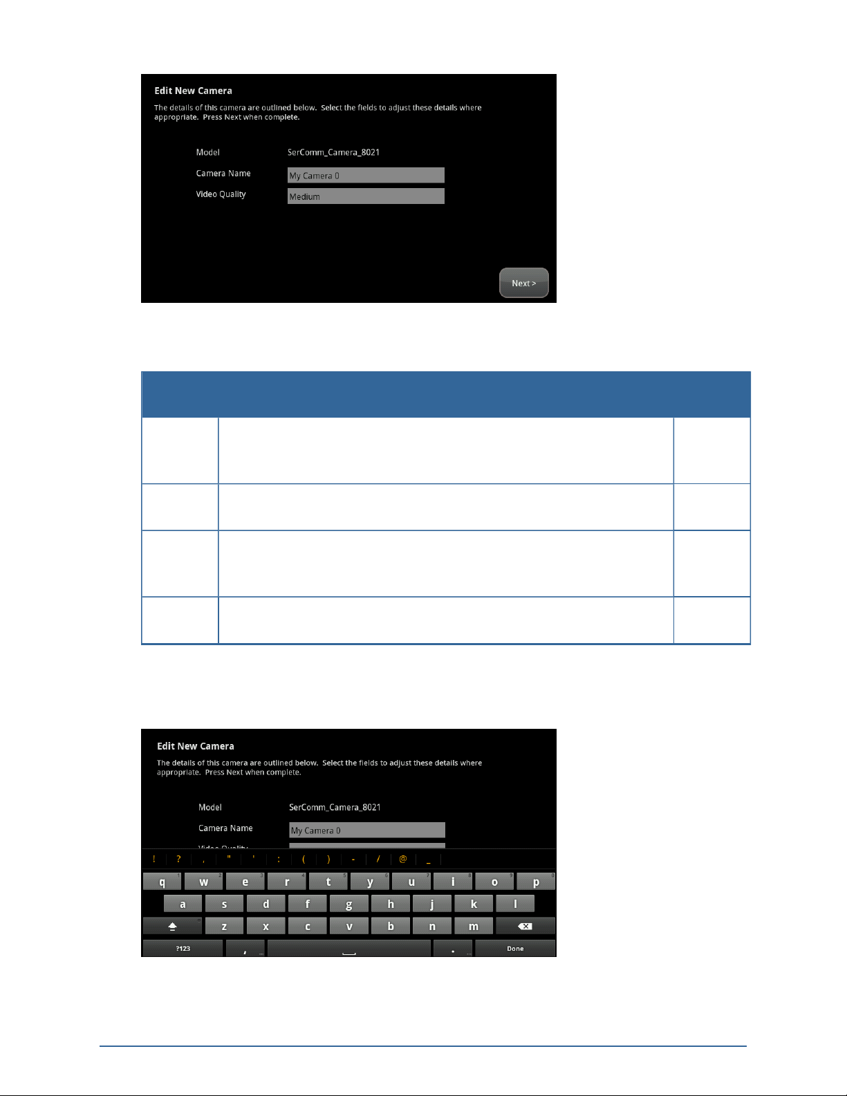
The Edit New Camera screen is displayed.
41
Page 42
Home System Installation Guide
Figure 36: Camera: Edit New Camera Screen
Table 3: Edit New Camera Options
Field Description
Model Model ID for the new camera. The camera manufacturer and model
Can Be
Modified?
No
information are sent to the server and logged for inventory reporting
and tech support purposes.
Camera
Name previously assigned to the camera device. Yes
Name
Associated
Zone
A camera can be assigned to zones for the following types of sensors:
door/window sensor, motion detector, glass break detector, smoke
Yes
detector.
Video
Level of video detail captured by the camera. Yes
Quality
7. Tap the Camera Name fields to display a keyboard screen and rename the Camera zone to something that clearly differentiates it from any other camera. Tap Done to accept your changes.
8. Tap the Associated Zone field to assign the camera to a security zone
42
Page 43

Installing the Security System
When a camera is assigned to a zone, it takes a series of pictures when an alarm is tripped at that
zone. A camera can be assigned to zones for the following types of sensors: door/window sensor,
motion detector, glass break detector, smoke detector.
Table 4: Associated Zone Menu Options for Cameras
Arming
Mode
Default
Camera
Unassigned
to Zone
<Security
Zone
Name>
9. Tap the Video Quality field to modify the level of video detail captured by the device.
a. Tap High, Medium or Low. Use a value with a network upload speed that is less than the
recommended upload network speed.
The Adjust Camera Video Quality screen is displayed.
If any door sensor not assigned to a camera trips an alarm, this camera takes a
series of pictures.
This camera is not associated with another sensor and it is not the Default camera.
This camera is associated with the selected zone. It takes a series of pictures
automatically when the zone trips an alarm, whether or not the alarm is ultimately
sent to the central monitoring station.
Description
b. To update the upload network speed, tap Run Speed Test.
43
Page 44

Home System Installation Guide
The TouchScreen uploads a file to the system servers to measure the time until it receives
an acknowledgement.
c. Tap Next to return to the Adjust Camera Video Quality screen.
d. Tap the appropriate video quality based on the measured speed, and tap Next.
10. Tap Next.
The Camera Wi-Fi Connection Test screen is displayed.
44
Figure 37: Camera: Adjust Camera Video Quality Screen
Page 45

Installing the Security System
Figure 38: Camera: Camera Wi-Fi Connection Test Screen
11. To have the camera connected to the TouchScreen wirelessly, follow the instructions in the Camera Wi-Fi Connection Test screen (including disconnecting the camera from the TouchScreen
router and rebooting the camera) and tap Locate Camera.
12. When the camera has been paired wirelessly to the TouchScreen, tap Next.
The Adjust Camera screen is displayed.
Figure 39: Camera: Adjust Camera Screen
13. Point the camera as needed.
14. Tap Next.
The Add Additional Camera screen is displayed.
Camera: Add Additional Camera Screen
15. Tap Add Another to add an additional camera. Repeat the steps as directed.
45
Page 46

Home System Installation Guide
Tap Next to return to the Install Zones and Home Devices screen is displayed with the Cameras
marked done.
16. If you are done configuring devices, tap Next to go to Step M: Testing the Alarm Functionality of
the Security System on page 65.
Table 5: Troubleshooting the Camera Installation
Issue Description
Unable to pair the camera to the TouchScreen Confirm that the camera is plugged into the security
router during configuration and has been restored to
factory defaults.
Perform the following procedure:
1. Reset the camera to factory defaults (hold the
reset button for 30 seconds).
2. Reboot the camera.
Located but not able to Secure Compare the MAC address on the screen with the MAC
address on the back of the camera. They should
match.
Poor picture, slow refresh in live-view, Wireless Camera Strength, no IP found (no LED
light on front of camera)
Intermittent connectivity Confirm good Wi-Fi connectivity.
Tapping on an upgrading camera in the camera widget produces an error dialog.
The camera image is replaced by an icon. In the camera widget on the TouchScreen, an upgrade
Relocate or reposition camera and then re-test.
The camera images are halted while the camera is
upgraded. When the upgrade is finished, the images
become available.
icon is displayed in place of the thumbnail image while
a camera is upgraded.
46
Page 47

Installing the Security System
Step H: Adding Lighting Devices to the Security System
Lighting devices control whether a light is turned on or off. The system can even manage dimmable
lights.
This action can be performed after wireless sensors are installed as described on Step F: Adding Sensors
to the Security System on page 28. You can skip this step and add the lighting devices later as described
on page 125.
IMPORTANT: If you need to update the firmware on any lighting device before adding it to the
security system, you must reset the lighting device to factory defaults before adding it
to the OpenHome Converge system. This is essential so that it can receive the
necessary changes to communicate with the TouchScreen.
The Install Zones and Home Devices screen is displayed.
1. Tap Lights.
The Locating Lighting Devices screen is displayed.
2. Tap Next.
3. Plug the lighting device into a wall socket. Secure it with a screw.
47
Page 48

Home System Installation Guide
The lighting devices should be unpaired when they are removed from their packaging. When one
is installed in socket, the LED flashes three times every five seconds indicating that it is in Search
mode and ready to pair with a TouchScreen. If you have problems pairing a lighting device, do the
following to reset it to factory default:
Press the On/Off button as you plug the device into the socket.
As lighting devices are found, an icon is displayed for that device.
4. When all the lighting devices are found, tap Done.
The system notes the number of devices that were found and paired.
48
Page 49

5. Tap Next.
The Configure Lighting Devices screen is displayed.
Installing the Security System
6. Tap a lighting device to configure it as described on page 125.
7. After all the lighting devices are configured, tap Next.
The Install Zones and Home Devices screen is displayed with Lights marked done.
8. If you are done configuring devices, tap Next to go to Step M: Testing the Alarm Functionality of
the Security System on page 65.
49
Page 50

Home System Installation Guide
Step I: Adding a Thermostat to the Security System
This action can be performed after wireless sensors are installed as described on Step F: Adding Sensors
to the Security System on page 28. You can skip this step and add a thermostat later as described on
page 121.
The Install Zones and Home Devices screen is displayed.
1. Tap Thermostats.
The Locating Thermostat Devices screen is displayed.
2. Tap Next.
The Locating Thermostat Devices screen is displayed.
3. Tap Next.
4. Reset the device to factory default to place it in Search mode.
a. Remove the cover at the top of the thermostat device.
A circuit board is displayed with a black button labeled Reset on the leftward side.
50
b. Press the Reset button.
The device is reset to factory default.
c. Press the Menu button twice.
d. In the tap screen, press the Mate label twice (below the radio tower icon).
Page 51

The Mate label begins blinking to indicate that the device is in Search mode.
When the thermostat device is found, an icon is displayed for that device.
5. Tap Done.
The system notes the number of devices that were found and paired.
Installing the Security System
6. Tap Next.
The Configure Thermostats screen is displayed showing all the paired thermostat devices.
7. Tap a device icon to configure it as described on page 121.
8. After all the thermostats are configured, tap Return to Menu.
The Install Zones and Home Devices screen is displayed with Thermostats marked done.
51
Page 52

Home System Installation Guide
9. If you are done configuring devices, tap Next to go to Step M: Testing the Alarm Functionality of
the Security System on page 65.
52
Page 53

Installing the Security System
Step J: Adding Key Fobs to the Security System
A key fob is a mobile tool that lets customers arm and disarm their system with the press of a button.
Note: This step can be performed after Activation.
IMPORTANT: If you need to update the firmware on any key fob before adding it to the security
system, you must reset the key fob to factory defaults before adding it to the
OpenHome Converge system. This is essential so that it can receive the necessary
changes to communicate with the TouchScreen.
The Install Zones and Home Devices screen is displayed.
1. Tap Key Fobs.
The Locating Key Fobs screen is displayed.
Figure 40: Key Fobs: Locating Key Fobs Screen
2. Tap Next to begin searching for key fobs to add.
A Stop button is displayed on the Locating Key Fobs screen. The TouchScreen searches for key
fobs that are available to be added (defaulted and in Search mode).
53
Page 54

Home System Installation Guide
3. Default a key fob and place it in Search mode.
When a key fob is found,an icon is displayed for it.
4. Press the star button to pair the found key fob.
The key fob is paired with the TouchScreen.
5. Repeat this procedure for each key fob with the TouchScreen. When all the key fobs have been
found and paired, tap Stop.
The Wireless Key Fobs Located screen notes the number of key fobs found and paired.
Figure 41: Key Fobs: Wireless Key Fobs Located Screen
6. Tap Next.
The Configure Wireless Key Fobs screen is displayed.
54
Page 55

Installing the Security System
Figure 42: Key Fobs: Configure Wireless Key Fobs Screen
7. Tap each key fob icon to configure the name that is used for it in the TouchScreen and Subscriber
Portal.
The Edit Keyfob screen is displayed.
2. Tap the Key Fob Label to display a keyboard.
3. Enter a name for the key fob. Tap Done..
55
Page 56

Home System Installation Guide
4. Tap the arrow to enable or disable the panic button.
5. Tap Done to return to the Configure Wireless Key Fobs screen
6. After all the key fobs are configured, tap Next.
The Install Zones and Home Devices screen is displayed with the Key Pads marked done.
7. If you are done configuring devices, tap Next to go to Step M: Testing the Alarm Functionality of
the Security System on page 65.
56
Page 57

Installing the Security System
Step K: Adding Key Pads to the Security System
A key pad provides customers a way to enter security codes without using the TouchScreen.
Note: This step can be performed after Activation.
IMPORTANT: If you need to update the firmware on any key pad before adding it to the security
system, you must reset the key pad to factory defaults before adding it to the
OpenHome Converge system. This is essential so that it can receive the necessary
changes to communicate with the TouchScreen.
The Install Zones and Home Devices screen is displayed.
1. Tap Key Pads.
The Locating Key Pads screen is displayed.
2. Tap Next to begin searching for key pads to add.
A Done button is displayed on the Locating Key Pads screen. The TouchScreen searches for key
pads that are available to be added (defaulted and in Search mode).
57
Page 58

Home System Installation Guide
3. Default a key pad and place it in Search mode.
When a key pad is found, an icon is displayed for it.
4.
Press the star button to pair the found key pad.
The key pad is paired with the TouchScreen and the icon shows a checkmark.
5. Repeat this procedure for each key pad with the TouchScreen. When all the key pads have been
found and paired, tap Done.
The Wireless Key Pads Located screen notes the number of key pads found and paired.
6. Tap Next.
The Configure Wireless Key Pads screen is displayed.
58
Page 59

Installing the Security System
7. Tap each key pad icon to configure the name that is used for it in the TouchScreen and Subscriber
Portal.
A keyboard screen is displayed.
8. Enter a name for the key pad, and tap Done to return to the Configure Wireless Key Pads screen.
9. After all the key pads are configured, tap Next.
The Install Zones and Home Devices screen is displayed with the Key Pads marked done.
59
Page 60

Home System Installation Guide
10. If you are done configuring devices, tap Next to go to Step M: Testing the Alarm Functionality of
the Security System on page 65.
60
Page 61

Installing the Security System
Step L: Adding Sirens to the Security System
A MAXIMUM of six IP cameras and 47 ZigBee devices are supported for the system. ZigBee devices consist of anything that communicates with the TouchScreen over radio
frequency, such as door/window sensors, lighting devices, thermostats, panel interface
devices, key pads, and key fobs and smoke detectors.
Once a sensor or peripheral has been paired to a TouchScreen, it MUST be deleted from
that TouchScreen before it can be paired to a different TouchScreen. When a sensor is
deleted from a TouchScreen, it is automatically reset to factory defaults and is placed in
Search mode, ready to be paired with another TouchScreen. It is possible to pair a
device to a second TouchScreen without deleting it from the original, but this could
result in the paired device not being registered in the server databases. This situation is
most often encountered in lab environments where TouchScreens and
sensors/peripherals are often swapped back and forth on a regular basis.
A siren is a multipurpose fire and burglar alarm signaling device that emits sound at levels greater than
85dB, loud enough to provide an audible alert and scare intruders. Some sirens also serve as a repeater,
which increases the range of your wireless devices and sensors. Refer to the documentation provided
with the siren to determine its capabilities.
IMPORTANT: If you need to update the firmware on any sensor before adding it to the security
system, you must reset the sensor to factory defaults before adding it to the
OpenHome Converge system. This is essential so that it can receive the necessary
changes to communicate with the TouchScreen.
Note: This step can be performed after Activation.
1. Tap Sirens.
The Locating Sirens screen is displayed.
61
Page 62

Home System Installation Guide
Figure 43: Locating Sirens Screen
See the installation documentation for the sirens to prepare them to be added to the
TouchScreen and to place them in Search mode.
Available sirens meet the following requirements:
Defaulted
Not currently paired with another TouchScreen device
Currently in Search mode
Note: See the siren installation documentation for how to tell if a siren is in Search mode,
how to tell if it is not in Search mode, and how to restart Search mode if it is not.
2. Tap Next.
The TouchScreen searches for sirens that are available to be added.
62
As sirens are found,an icon is displayed for that siren.
Page 63

Installing the Security System
3. Fault each found siren to pair it to the TouchScreen.
The siren is paired with the TouchScreen and the icon shows a checkmark.
4. Determine that all the sirens have been located by the TouchScreen.
5. When all the sirens are found and paired, tap Done.
Note: Any located sirens that were not paired are released by the TouchScreen. Sirens can
be added later (see page 96).
The Wireless Sirens Located screen notes the number of wireless sirens found and paired.
6. Tap Next.
The Configure Wireless Sirens screen is displayed showing icons representing the sirens that were
located and paired.
7. Tap each siren icon to configure it.
The Settings screen is displayed.
63
Page 64

Home System Installation Guide
Enter a new label for the siren, if desired. Tap Done to save your changes.
The wireless sirens are marked as configured.
8. From this point you can configure any or all of the following devices:
Panel Interfaces (see Step E: Adding Panel Inter-
face Modules to the Security System on page 24)
Cameras (see Step G: Adding Cameras to the
Security System on page 38)
Lights (see Step H: Adding Lighting Devices to the
Security System on page 47)
After all the devices are configured—or if you want to configure the devices later—tap Next to go to Step
M: Testing the Alarm Functionality of the Security System on the facing page.
Thermostats (see Step I: Adding a Ther-
mostat to the Security System on page
50)
Key Fobs (see Step J: Adding Key Fobs to
the Security System on page 53)
Key Pads (see Step K: Adding Key Pads
to the Security System on page 57)
64
Page 65

Installing the Security System
Step M: Testing the Alarm Functionality of the Security System
The Test Alarm screen is displayed.
Figure 44: Alarm Testing: Test Alarm Screen
This step sends a test alarm, through the system servers, to the central monitoring station as though a
genuine alarm has been tripped.
1. Tap Test Alarm.
The TouchScreen informs you that the signal was sent to the central monitoring station. In the
event reports on the Management Portal Account Information screen (History tab and Alarms
tab), this event is reported as “alarm test mode”.
2. After the test alarm has been sent, tap Next.
The Verify Signal Sent to Central screen is displayed providing a phone number to the central
monitoring station and the confirmation information of the current customer account.
65
Page 66

Home System Installation Guide
Figure 45: Alarm Testing: Verify Signal Sent to Central Screen
3. Call the provided phone number and give the confirmation information to the representative.
4. When you have confirmed that the test alarm was sent successfully, tap Next.
The Alarm Test Checklist is displayed.
Figure 46: Alarm Testing: Alarm Test Checklist Screen
5. Ensure that all the security zones are not faulted (that is, doors and windows are closed, motion
detectors do not show motion, etc.).
When the security zones are ready for testing, “Ready to Arm” is displayed under the Arm
button.
6. Tap Arm.
The after a ten second Exit Delay period, the button changes to the label System Armed.
66
Page 67
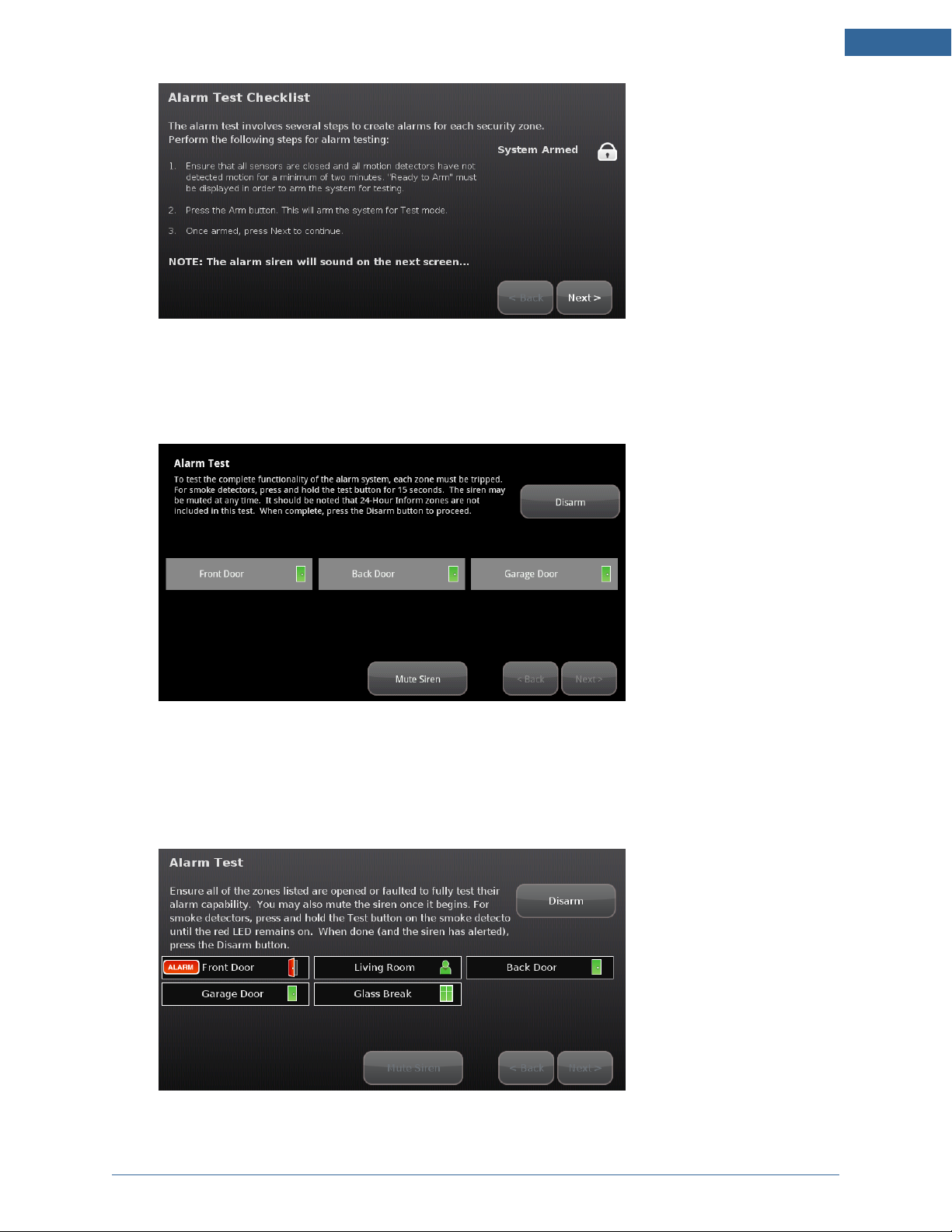
Figure 47: Alarm Testing: Alarm Test Checklist Screen
1. Tap Next.
The Alarm Test screen is displayed.
Installing the Security System
Figure 48: Alarm Testing: Alarm Test Screen
2. Fault each alarm in turn.
The TouchScreen notes that each sensor communicated an event to the TouchScreen and
initiated an alarm.
3. After all the alarms have been faulted and the system has noted it, tap Disarm.
67
Page 68

Home System Installation Guide
4. Tap Next.
The Review Alarms screen is displayed showing the phone number to contact the central
monitoring station to ensure they received all the generated alarms.
Figure 49: Alarm Testing: Review Alarms Screen
5. Contact the central monitoring station.
6. If they received all the generated alarms, tap Next.
See Testing Alarms on page 81, for how to test alarms after the installation is complete.
68
Page 69

Installing the Security System
Step N: Setting and Validating the Security Information
The Master code is the keypad code that is required for the customer to access the Settings app and to
create and manage other codes.
The Set Master Code is displayed.
Figure 50: Set Master Code Screen
1. Tap Next.
A keypad is displayed.
2. Enter a four-digit code twice, and tap Done.
The Getting Account Information From Server screen is displayed.
69
Page 70

Home System Installation Guide
Figure 51: Validate Account Information: Getting Account Information From Server Screen
3. Tap Next.
The Validate Account Information screen is displayed.
Figure 52: Validate Account Information: Validate Account Information Screen
4. Ensure that the displayed account information for the customer is accurate—especially the following:
Phone number that the central monitoring station calls after an alarm
Email address that receives an email necessary to perform the Subscriber Portal activation
Note: This information is associated with the Activation code you entered.
5. Tap Next.
The Getting Security Secret Word From Server screen is displayed.
70
Page 71

Figure 53: Set Secret Word: Getting Security Secret Word From Server Screen
6. Tap Next.
The Set Security Secret Word screen is displayed.
Installing the Security System
Figure 54: Set Secret Word: Set Security Secret Word Screen
7. Show the customer the secret word displayed on the screen. Explain that this is the word that
they give to the central monitoring station when it calls to verify whether an alarm is false.
8. Tap the Secret Word field.
A keyboard screen is displayed.
71
Page 72

Home System Installation Guide
9. Have the customer type a new secret word and then tap Done.
The Set Security Secret Word screen is displayed again.
10. Tap Next.
The Activation Complete screen is displayed.
Figure 55: Activation Complete Screen
11. Tap Reboot TouchScreen.
72
Page 73

The TouchScreen reboots.
Installing the Security System
73
Page 74

Home System Installation Guide
Step O: Mounting the Sensors
1. Mount the sensors and peripherals as described in the sensor documentation.
2. Test each sensor’s signal strength as described on page 100.
IMPORTANT: The minimum distance for the sensors to communicate with the TouchScreen is
beyond most practical limits. However, the distance can be limited occasionally by the
materials for the walls, electrical interference, and other conditions.
74
Page 75

Installing the Security System
Step P: Configuring the TouchScreen
If necessary, perform the following operations:
Modify the Entry and Exit delay time periods (see page 85)
Modify the Alarm Transmission delay (see page 86)
Modify the “swinger shutdown” (see page 87)
Reset the TouchScreen to factory defaults (see page 87)
Note: This causes the device to require activation again, which in turn requires that the customer’s
account be reset as well.
Check for a new firmware update (see page 90)
Manage the sensors/security zones (see Table 6: Sensor Operations on page 76)
Manage the cameras (see Table 7: Manage Camera Operations on page 77)
Manage key fobs and key pads (see Table 8: Manage Peripheral Operations on page 77)
Manage lights and thermostats (see Table 9: Manage Environmental Device Operations on page
78)
Technicians also can perform the following general activities that are available to the customer.
Note: See the TouchScreen User's Guide for information about these activities.
Manage the way sensors are listed in TouchScreen reports and tools
View and test the TouchScreen’s connectivity to the central monitoring stations
Manage the keypad codes and secret word
View the customer’s account information
Manage your TouchScreen device sounds, screensaver, etc.
View technical information about the TouchScreen device
75
Page 76

Home System Installation Guide
Sensors consist of door/window sensors, motion detectors, glass break detectors, and smoke alarms.
Table 6: Sensor Operations
Operation Description
Modify sensor details
Delete a
sensor
Add a sensor
Create a
cross zone
association
View sensor diagnostics
Manage
fire alarm
settings
Change (within limits) the details of a sensor (see page 95).
Remove a sensor from being managed by the TouchScreen (see
Use these actions in sequence to reset a sensor’s
IP/MAC addresses to factory default.
page 98).
Find a new sensor that is available
to be added (see page 96).
Configure two sensors to trip an alarm only if they are both faulted (see page 104). For
example, an alarm sounds when a door sensor is faulted ONLY if an associated motion
sensor also is faulted.
View the connectivity details and signal strength of a sensor (see page 100).
Toggle Fire Alarm Verification to
determine how the system triggers
fire alarms (see page 92
Disabled Central monitoring station
is contacted when one
smoke alarm sounds.
Enabled Central monitoring station
is notified when:
Multiple smoke
detectors sound an
alarm.
One smoke detector
sounds an alarm for
60 seconds.
76
Page 77

Table 7: Manage Camera Operations
Operation Description
Modify a camera
Change the name identifying each camera in the TouchScreen and the
Subscriber Portal.
Set or modify the zone to which the camera is assigned. When a camera is
assigned to a zone, the camera takes a series of pictures if that zone trips an
alarm.
Installing the Security System
Delete the camera
from the security
system
Add a camera to the
security system
Remove a camera from being managed by the TouchScreen (see page
119).
Add an additional camera to the
TouchScreen – up to six (see page
Use these actions in sequence to reset a
sensor’s IP/MAC addresses to factory
default.
112).
Replace a camera Swap the current camera with another one (see page 120).
Table 8: Manage Peripheral Operations
Operation Description
Delete a
key fob
Add a key
fob
Modify a
key fob
Delete a
key pad
Add a key
pad
Remove a key fob from being able to access
the security system (see page 130).
Use these actions in sequence to reset a
key fob’s details to factory default.
Find a new key fob that is available to be
added (see page 130).
Change the name identifying each key fob in the TouchScreen and the Subscriber Portal
(see page 129).
Remove a key pad from being able to access
the security system (see page 138).
Use these actions in sequence to reset a
key pad’s details to factory default.
Find a new key pad that is available to be
added (see page 135).
Modify a
key pad
Change the name identifying each key pad in the TouchScreen and the Subscriber Portal
(see page 135).
77
Page 78

Home System Installation Guide
Table 9: Manage Environmental Device Operations
Operation Description
Delete a lighting
device
Add a lighting
device
Modify a lighting
device
Delete a thermostat
Add a thermostat Pair a new thermostat to your system (see page 121).
Modify a thermostat
Remove a lighting device from your system (see page 128).
Pair a new lighting device to your system (see page 127).
Change the name identifying each key fob in the TouchScreen and the Subscriber
Portal (see page 125).
Remove a thermostat from your system (see page 124).
Change the name identifying each key pad in the TouchScreen and the Subscriber
Portal (see page 123).
78
Page 79

Installing the Security System
Step Q: Activating the Subscriber Portal
1. With the customer, check the inbox for the email address of the customer’s account (the address
displayed on the Validate Account Settings screen).
The customer has received an email notification that the security system has been activated. The
email provides a temporary username and password to the Subscriber Portal. The Subscriber
Portal provides options for managing account and security settings.
2. Note the temporary password in the email and click the link in the email.
The Subscriber Portal login is displayed. The temporary username field is already filled in.
3. In the password field, enter the temporary password that was provided in the email.
Step 1 of the activation process is displayed.
4. Enter the Master code you set during the TouchScreen activation.
5. Tap Next.
Step 2 of the activation process is displayed.
6. Enter (twice) a username and a password that the customer will use to access the Subscriber Portal.
7. Tap Next.
The Subscriber Portal is displayed.
8. Have the customer save the URL of the Subscriber Portal to the bookmarks in their browser.
79
Page 80

Home System Installation Guide
Technician Operations
Customers can use the Settings menu to access a variety of operations to configure and maintain their
security system as described in the iControl TouchScreen User's Guide. When an installer accesses the
Settings menu with an Installer keypad code, he has access to operations available to the customer as
well as other operations unavailable to a customer.
Getting Started
To access the Installers Settings menu:
1. From the Home screen, tap the Settings app.
A keypad is displayed.
2. Enter the Installers keypad code.
Note: Not the customer’s Master keypad code.
A keyboard screen is displayed.
3. Enter your Technician Code and tap Done.
80
Page 81
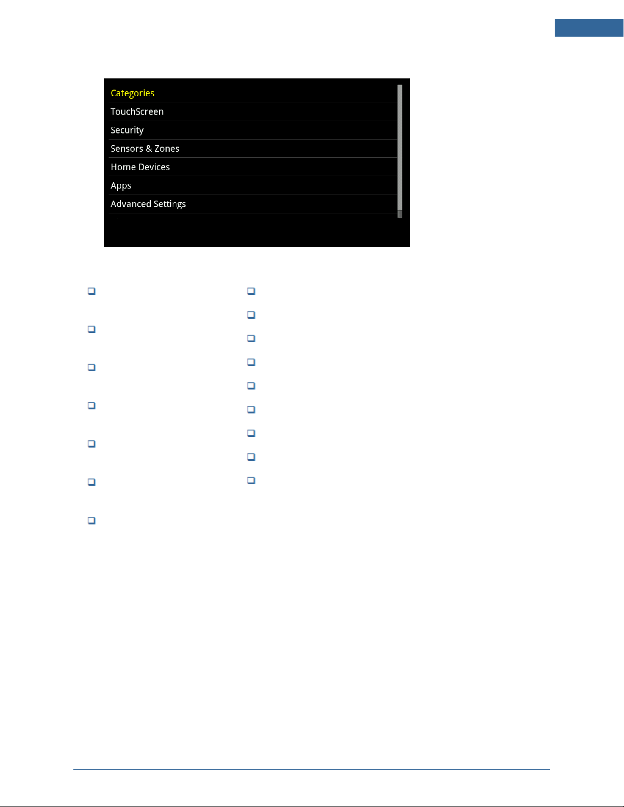
The Installer Settings menu is displayed.
The following Installer operations are available from the Installer Settings menu:
Technician Operations
Configure the Entry/Exit
delay periods (page 85)
Configure the Alarm Transmission delay (page 86)
Configure the Swinger Shutdown feature (page 87)
Reset the TouchScreen to
factory defaults (page 88)
Check for new firmware versions (page 90)
Manage sensors and zones
(page 94)
Create cross-zone associations for sensors (page
104)
Both customers and Installers can test the alarm capabilities by following the procedure described on
page 81.
Manage the camera (page 112)
Manage the lighting devices (page 125)
Manage thermostats (page 121)
Manage key fobs (page 129)
Manage key pads (page 135)
Manage Panel Interfaces (page 139)
Perform the RMA procedure (page 146)
Reset your managed router (see the TouchScreen User Guide )
Allow or block an unmanaged router passing through the
iControl DMZ (see the TouchScreen User Guide )
Testing Alarms
Installers can test the alarm system without going through the entire activation process.
To test alarms (after activation):
1. Call the central monitoring and tell them you are about to test the system.
2. From the Installers Settings app (see page 80), tap Security > Alarm Test.
The Alarm Test Options screen is displayed.
81
Page 82

Home System Installation Guide
Figure 56: Settings: Alarm Test Options Screen
3. To have your test alarms reported to central monitoring, tap Disabled.
The button changes to Enabled. Your test alarms are sent to the central monitoring station.
Note: If the Enabled button is already displayed, tap Enabled to choose to have your test
alarms NOT sent to central monitoring.
IMPORTANT: If you enable Send Test Alarm Messages, contact the central monitoring station
and tell them you are testing your system.
4. Ensure all the security zones are not faulted (that is, doors and windows are closed, motion detectors do not show motion, etc.).
The Alarm Test Checklist is displayed.
Figure 57: Settings: Alarm Test Checklist Screen
5. Ensure all the security zones are not faulted (that is, doors and windows are closed, motion detectors do not show motion, etc.).
82
Page 83

Technician Operations
When the security zones are ready for testing, “Ready to Arm” is displayed under the Arm
button.
6. Tap Arm.
Your security system is armed in the special Test mode. The Exit Delay is only ten seconds long.
Motion sensors are turned off (not tripping alarms but recording events) until an Entry/Exit
security zone is faulted.
The Arm button changes to a System Armed notice.
7. Tap Next.
The Alarm Test screen is displayed.
Figure 58: Alarm Testing:Alarm Test Screen
8. Open and close an Entry/Exit door.
The Entry Delay period starts (default 30 seconds). The TouchScreen begins beeping once per
second. The beeping speeds up to twice per second in the last ten seconds of the Entry Delay
period. The motion detectors are turned on.
Note: To mute the siren, tap Mute Siren. This is not recommended. Ensuring that your siren
is in working order is an important part of the test.
After the end of the Entry Delay period ends, the siren sounds (unless you muted it) and the
Entry/Exit zone you faulted is marked with an alarm tag.
83
Page 84

Home System Installation Guide
Figure 59: Settings: Alarm Test Screen
9. Fault each additional alarm as described in the following table and ensure that it is marked as
alarm.
Table 10: Sensor Testing Operations
Sensor Testing Process
Door/Window Open and close the door or window.
Motion Detector
Smoke Detector
Glass Break
Avoid the motion detector’s view for three minutes after arming the system,
then walk in front of it.
Press and hold the sensor’s “Test” button until the siren sounds, approximately ten seconds.
Use a glass break simulator.
Detector
Key Fob Arm and disarm the system with the key fob.
Key Pad Arm and disarm the system with the key pad.
The TouchScreen notes that each sensor communicated an event to the TouchScreen and
initiated an alarm.
10. After all the alarms have been faulted and the system has noted it, tap Disarm.
11. Tap Next.
The Review Alarms screen is displayed showing a history of the zones in your system.
84
Page 85

Technician Operations
Figure 60: Settings: Review Alarm Screen
12. Review the zone event history.
13. Ensure you have received any configured alerts via email or SMS.
14. If you enabled Send Test Alarm Messages, contact the central monitoring station's Test number
to ensure that they received all the generated alarms. If all the alarms were received successfully,
tell them that you are no longer testing alarms.
15. Tap Next to return to the Settings menu.
Configuring the Entry/Exit Delay Periods
The Entry Delay period is the amount of time from an Entry/Exit sensor being faulted until an alarm
sounds. The customer has until the end of the Entry Delay period to enter a valid keypad code. There is
no Entry Delay period for Perimeter type sensors (such as window sensors or non-entry door sensors).
There is an audible beeping during the Entry Delay period. This beeping sound is not configurable and
cannot be muted.
UL Installations: For UL residential burglary alarm installations, the Entry Delay period shall not be set
above a maximum of 45 seconds.
SIA Guidelines: The Entry Delay time must default to 30 seconds. The combined Entry Delay and abort
window should not exceed 1 minute.
The Exit Delay period is the amount of time that starts when the security system is armed. The customer
has this period of time to exit through an Entry/Exit sensor doorway. If the customer does not exit during
this period, the system cannot be armed in Arm Away state. The system arms in Arm Stay state. There is
an audible beeping during the Exit Delay (once per second) that speeds up during the last 10 seconds of
the Exit Delay (twice per second).
UL installations: For UL residential burglary alarm installations, the Exit Delay time shall not exceed 120
seconds.
SIA Guidelines: The Exit Delay time defaults to 60 seconds. The minimum Exit Delay is 45 seconds.
The Entry/Exit Delay periods are configurable by an Installer only.
Note: The default Entry/Exit Delay periods may be different than the values shown.
85
Page 86

Home System Installation Guide
To configure the Entry/Exit Delay periods:
1. From the Installer Settings menu, tap Security >Entry And Exit Delay.
The Entry and Exit Delay screen is displayed.
Figure 61: Settings: Entry and Exit Delay Screen
2. Tap the right and left-pointing arrows to increase and decrease the Entry Delay and Exit Delay periods by increments of five seconds.
3. Tap Return to Menu.
Note: The Entry/Exit Delay periods cannot be less than 30 seconds. In most cases, these periods
should not exceed 60 seconds.
Configuring the Alarm Transmission Delay
The Alarm Transmission Delay period (also called the Abort Window) is the length of time after an alarm
sounds for the customer to enter a valid key pad code before the central monitoring station is contacted.
This period starts when the customer fails to enter his key pad code during the Entry Delay period. The
central monitoring station is not contacted until after the Alarm Transmission Delay period. This helps
prevent false alarms.
The Alarm Transmission Delay period is configurable by an Installer.
86
Page 87

To configure the Alarm Transmission Delay period:
1. From the Installer Settings menu, tap Security >Alarm Transmission Delay.
The Alarm Transmission Delay screen is displayed.
Technician Operations
Figure 62: Settings:Alarm Transmission Delay Screen
2. Tap the right and left-pointing arrows to increase and decrease the Alarm Transmission Delay
period.
Note: The Alarm Transmission Delay period cannot be less than 15 seconds or exceed 45
seconds.
3. Tap Return to Menu.
Configuring the Swinger Shutdown Feature
The Swinger Shutdown feature helps prevent a runaway TouchScreen from tying up the central
monitoring station. After the TouchScreen has sent an alarm the set number of times (trips) to the
central monitoring station, no more alarms are sent for 48 hours or until the security system is disarmed.
87
Page 88

Home System Installation Guide
To configure the swinger shutdown:
1.
From the Installer Settings menu, tap Security ® Swinger Shutdown.
The Swinger Shutdown Settings screen is displayed.
Figure 63: Settings: Swinger Shutdown Settings
2. Tap the right and left-pointing arrows to increase and decrease the number of swinger shutdown
trips (Maximum Trips).
Note: The number of trips cannot be less than 1 or exceed 6.
3. Tap Swinger Shutdown Enabled to disable this feature.
Tap Swinger Shutdown Disabled to enable this feature.
Resetting the TouchScreen to Factory Defaults
When an activated TouchScreen is reset to factory defaults, the customer’s account must also be reset
by Customer Care in order for it to be reactivated.
To reset the TouchScreen:
1. Ensure you have the premise passphrase for the account.
2.
From the Installer Settings menu, tap Advanced Settings ® Reset to Factory Defaults.
88
Page 89

The Reset Touchscreen to Factory Defaults screen is displayed.
Technician Operations
3. Tap Reset to Factory Defaults.
The Keypad screen is displayed.
4. Enter the Installer keypad code.
The Keyboard screen is displayed.
89
Page 90

Home System Installation Guide
5. Enter the PREMISE PASSPHRASE for the current account.
The device resets and the Installation screen is displayed.
To activate the system again:
1. Contact Customer Care to have the customer’s account reset.
2. Follow the steps starting on page 14 to activate the system again.
Checking for New Firmware Updates for the TouchScreen
You can have a TouchScreen look for an available update on the server or install an update from a USB
drive (see page 91).
To check for a firmware update on the server:
1.
From the Installer Settings menu, tap Advanced Settings ® Check for Firmware Update.
90
The Checking for Firmware Upgrade screen is displayed. The TouchScreen immediately checks for
newer firmware updates that are available to be installed on the device’s hardware version.
 Loading...