

Page 1

w w w . t e c h n i c o l o r . c o m / m c s
Page 1
Technicolor COM3000
Integrator’s Manual
Page 2

w w w . t e c h n i c o l o r . c o m / m c s
Page 2
Revision Record
Revision
Date
Revision Editor
Revision Description
1.1
6/7/2018
Angelo Peruch
Final draft for Distribution 6/7/2018
Contents
1 Definitions ................................................................................................................................. 10
Page 3

w w w . t e c h n i c o l o r . c o m / m c s
Page 3
2 Introduction ............................................................................................................................... 13
2.1 Intended Usage ............................................................................................................................... 13
3 COM3000 Product Description ................................................................................................. 14
3.1 Additional Features ......................................................................................................................... 15
4 Compatibility with Previous Hardware ..................................................................................... 16
5 Mechanical Overview ................................................................................................................ 17
5.1 COM400 Chassis .............................................................................................................................. 17
6 COM51 Card ............................................................................................................................. 18
6.1 COM51A .......................................................................................................................................... 19
7 QAM20 ...................................................................................................................................... 20
8 System Connections .................................................................................................................. 21
..................................................................................................................................................................... 21
Pre-Installation .................................................................................................................................. 22
9 Training and Support ................................................................................................................. 22
10 Required Tools .......................................................................................................................... 22
11 Pre-Installation Site Requirements ............................................................................................ 22
11.1 Site Survey ....................................................................................................................................... 22
11.2 Distribution Networks ..................................................................................................................... 25
12 Channel Lineup.......................................................................................................................... 25
13 External Video Sources ............................................................................................................. 26
14 TV Compatibility ....................................................................................................................... 26
15 Installation Guidelines ............................................................................................................... 27
16 AT&T / DIRECTV Activation .................................................................................................. 27
17 Getting Started ........................................................................................................................... 28
17.1 Assembly ......................................................................................................................................... 28
17.2 Setting up Multiple Chassis ............................................................................................................. 29
17.3 Chassis Dipswitch ............................................................................................................................ 29
17.4 Chassis Dipswitch Settings .............................................................................................................. 30
18 System Power Up ...................................................................................................................... 30
18.1 System startup LED Behavior .......................................................................................................... 30
Boot up ........................................................................................................................................................ 31
18.2 LED Behavior after Boot up ............................................................................................................. 32
19 COM400 Chassis ....................................................................................................................... 33
Page 4

w w w . t e c h n i c o l o r . c o m / m c s
Page 4
19.1 Accessing the COM400 User interface ............................................................................................ 33
19.2 Setting a Password .......................................................................................................................... 33
IGMP Activation .......................................................................................................................................... 34
19.3 IGMP Port Settings .......................................................................................................................... 34
19.4 Save Changes to Startup Configuration .......................................................................................... 34
19.5 COM400 Software Version .............................................................................................................. 35
19.6 COM400 Software Update .............................................................................................................. 35
20 The COM3000 Web Interface ................................................................................................... 36
20.1 User Passwords ............................................................................................................................... 37
21 COM51 Tuner Licensing ........................................................................................................... 38
22 Overview Page ........................................................................................................................... 40
22.1 QAM Summary ................................................................................................................................ 41
22.2 Display Options ............................................................................................................................... 41
22.3 Channel Tuning Options .................................................................................................................. 42
23 Discover Page ............................................................................................................................ 45
23.1 Explanation of Discover Page Fields ................................................................................................ 46
24 Advanced Edit ........................................................................................................................... 48
24.1 The Basic Channel Tune Screen....................................................................................................... 48
24.2 Advanced Tune ................................................................................................................................ 49
24.3 Informational Status........................................................................................................................ 53
24.4 COM51 LED Control Feature ........................................................................................................... 55
24.5 COM51 CAM Log Data ..................................................................................................................... 56
24.6 COM51 Software Reset ................................................................................................................... 57
24.7 COM51 File Transfer Utility ............................................................................................................. 57
24.8 COM51 User Configuration Options ............................................................................................... 58
24.9 COM51 “Direct Tune” Feature ........................................................................................................ 61
24.10 Remote Access Feature ............................................................................................................... 61
24.11 Using the VidPlay Feature ........................................................................................................... 62
24.12 Setup for Vidplay.exe .................................................................................................................. 62
24.13 Using the COM51 “Simulcrypt” Feature ..................................................................................... 64
24.14 Displaying COM3000 Status ........................................................................................................ 64
25 Pairing Info ................................................................................................................................ 65
Page 5

w w w . t e c h n i c o l o r . c o m / m c s
Page 5
26 Tune All ..................................................................................................................................... 69
27 Help ........................................................................................................................................... 71
28 SysInfo ....................................................................................................................................... 71
29 HealthInfo .................................................................................................................................. 72
30 EPG ............................................................................................................................................ 73
31 Syslog ........................................................................................................................................ 74
32 EPG Overview ........................................................................................................................... 75
32.1 Guide.XML Overview ....................................................................................................................... 77
32.2 Getting Started with EPG ................................................................................................................ 78
32.3 EPG Customization and Channel Mapping ...................................................................................... 81
32.4 EPG editing ...................................................................................................................................... 81
32.5 Logo Creation and Upload ............................................................................................................... 82
33 Welcome Screen ........................................................................................................................ 83
33.1 Welcome Screen Image Creation .................................................................................................... 83
33.2 Uploading Welcome Screens to COM3000 ..................................................................................... 86
33.3 Adding Welcome Screens to Guide Data ........................................................................................ 87
33.4 Disabling Welcome Screens ............................................................................................................ 87
34 QAM20 ...................................................................................................................................... 88
34.1 Accessing the QAM Page ................................................................................................................. 88
34.2 Checking Software Version and License Count ............................................................................... 89
34.3 Setting QAM Output Channels ........................................................................................................ 89
34.4 Setting Unique RF output to a QAM ............................................................................................... 92
34.5 Setting Unique outputs to a group of QAMs .................................................................................. 93
35 Troubleshooting ......................................................................................................................... 94
35.1 Software Version ............................................................................................................................. 94
35.2 Verify RF .......................................................................................................................................... 94
35.3 COM51 Reset Button ...................................................................................................................... 94
35.4 Troubleshooting Common Problems .............................................................................................. 95
35.5 Features and Licensing .................................................................................................................... 95
36 Preventing Pro:Idiom Key Loss ................................................................................................ 96
37 Simultaneous QAM and Multicast IP Output ............................................................................ 96
38 Syslog Server Setup ................................................................................................................... 98
39 Open Software Notification ..................................................................................................... 101
Page 6

w w w . t e c h n i c o l o r . c o m / m c s
Page 6
Page 7

w w w . t e c h n i c o l o r . c o m / m c s
Page 7
Table of Figures
FIGURE 1 - COM3000 ........................................................................................................................ 14
FIGURE 2 - COMPATIBILITY MATRIX .................................................................................................. 16
FIGURE 3 COM400 CHASSIS .............................................................................................................. 17
FIGURE 4 - COM51 CARD .................................................................................................................. 18
FIGURE 5 - QAM20 ............................................................................................................................ 20
FIGURE 6 - COM51 SYSTEM DIAGRAM.............................................................................................. 21
FIGURE 7 - INSTALLATION OF THE QAM20 AND COM51 .................................................................. 28
FIGURE 8 – COM400 DIPSWITCH ACCESS PANEL .............................................................................. 29
FIGURE 9 - CHASSIS ID DIPSWITCH .................................................................................................... 29
FIGURE 10 - LED BEHAVIOR AT BOOT UP ......................................................................................... 31
FIGURE 11 - OPERATIONAL LED BEHAVIOR ...................................................................................... 32
FIGURE 12 - ETHERNET SWITCH INTERFACE ...................................................................................... 33
FIGURE 13 - NETWORK SWITCH PASSWORD ....................................................................................... 33
FIGURE 14 - IGMP SNOOPING SETTINGS ........................................................................................... 34
FIGURE 15-SAVE START-UP CONFIGURATION ................................................................................... 34
FIGURE 16 - COM400 SOFTWARE VERSION ...................................................................................... 35
FIGURE 17 – COM400 SOFTWARE UPGRADE .................................................................................... 35
FIGURE 18 - COM3000 USER INTERFACE INTRODUCTION PAGE ....................................................... 36
FIGURE 19 PASSWORD CHALLENGE ................................................................................................... 37
FIGURE 20 - LOCK SCREEN ................................................................................................................ 37
FIGURE 21 - SYSINFO PAGE TUNER COUNT ....................................................................................... 38
FIGURE 22 - COM51 TUNER LICENSING ............................................................................................ 38
FIGURE 23 - COM3000 OVERVIEW PAGE .......................................................................................... 40
FIGURE 24 - QAM SUMMARY ............................................................................................................ 41
FIGURE 25 – ENCRYPTION SETTINGS ................................................................................................. 42
FIGURE 26 - CHANNEL SELECTION DROP DOWN ................................................................................ 43
FIGURE 27 - OUTPUT MODE ............................................................................................................... 43
FIGURE 28 - MAJOR/MINOR CH OR IP AND PORT SETTINGS............................................................... 43
FIGURE 29 - BITRATE DISPLAY .......................................................................................................... 44
FIGURE 30 - SNR AND SIGNAL STRENGTH ......................................................................................... 44
FIGURE 31 - COM51 DISCOVER PAGE ............................................................................................... 45
FIGURE 32 - COM51 BASIC TUNE SCREEN ........................................................................................ 48
Page 8

w w w . t e c h n i c o l o r . c o m / m c s
Page 8
FIGURE 33 - ADVANCED TUNE SCREEN ............................................................................................. 49
FIGURE 34 - "INFO" SECTION OF THE ADVANCED EDIT PAGE ............................................................ 53
FIGURE 35 - NETWORK ID AND FREQUENCY INDEX ........................................................................... 54
FIGURE 36 - LED CONTROL ............................................................................................................... 55
FIGURE 37 - CAM LOG INTERFACE.................................................................................................... 56
FIGURE 38 - CAM LOG REPORT .......................................................................................................... 56
FIGURE 39 - RESET INTERFACE .......................................................................................................... 57
FIGURE 40 - FILE TRANSFER INTERFACE ............................................................................................ 57
FIGURE 41 - USER CONFIG INTERFACE ............................................................................................... 58
FIGURE 42 - DIRECT TUNE INTERFACE .............................................................................................. 61
FIGURE 43 - REMOTE ACCESS FEATURE ............................................................................................ 61
FIGURE 44 - VID PLAY ....................................................................................................................... 62
FIGURE 45 - COM3000 PAIRING INFO PAGE ...................................................................................... 65
FIGURE 46 - COM46 MULTI CARD UPGRADE .................................................................................... 67
FIGURE 47 - COM51 TUNE ALL......................................................................................................... 69
FIGURE 48 - HELP TAB ....................................................................................................................... 71
FIGURE 49 - COM51 SYS INFO PAGE ................................................................................................. 71
FIGURE 50 - COM3000 HEALTH INFO PAGE ...................................................................................... 72
FIGURE 51 - SYSLOG EXAMPLE .......................................................................................................... 74
FIGURE 52 - SYSINFO EPG ................................................................................................................. 75
FIGURE 53 - IPG SETUP PAGE ............................................................................................................ 77
FIGURE 54 - COM3000 EPG PAGE .................................................................................................... 78
FIGURE 55- COM51 EPG LOAD ........................................................................................................ 80
FIGURE 56 - EPG CHANNEL ............................................................................................................... 81
FIGURE 57 - EPG LOGO CREATION .................................................................................................... 82
FIGURE 58 - GUIDE CHANNEL WITH CUSTOM LOGO .......................................................................... 82
FIGURE 59 WELCOME PAGE POWERPOINT SLIDE .............................................................................. 83
FIGURE 60 - WELCOME SCREEN IMAGE CREATION ............................................................................ 83
FIGURE 61 - WELCOME SCREEN SETTINGS USING MICROSOFT PAINT ............................................... 85
FIGURE 62 - CORRECTLY SIZED WELCOME SCREEN IMAGE ............................................................... 85
FIGURE 63 UPLOAD FILE TO COM51 TFTP ....................................................................................... 86
FIGURE 64 - UPLOAD WELCOME SCREEN IMAGE TO EPG .................................................................. 86
FIGURE 65 - ADDING WELCOME SCREEN TO EPG AND PSIP ............................................................. 87
Page 9

w w w . t e c h n i c o l o r . c o m / m c s
Page 9
FIGURE 66 - VERIFY WELCOME SCREEN IS STREAMING ..................................................................... 87
FIGURE 67 - QAM SUMMARY HYPERLINK ......................................................................................... 88
FIGURE 68 - QAM TAB IP ENTRY ...................................................................................................... 88
FIGURE 69 - QAM SOFTWARE AND LICENSE COUNT ......................................................................... 89
FIGURE 70 - SETTING QAM OUTPUTS ............................................................................................... 89
FIGURE 71 QAM TABLE .................................................................................................................... 90
FIGURE 72 -QAM TABLE ................................................................................................................... 91
FIGURE 73 - CHANGING A SINGLE QAM OUTPUT .............................................................................. 92
FIGURE 74 - INDIVIDUAL QAM OUTPUT CHANGE ............................................................................. 92
FIGURE 75 - CHANGING OUTPUTS CHANNELS ON A GROUP OF QAMS .............................................. 93
FIGURE 76 - QAM GROUP OUTPUTS .................................................................................................. 93
FIGURE 77 - COM51 RESET ............................................................................................................... 95
Page 10

w w w . t e c h n i c o l o r . c o m / m c s
Page 10
1 Definitions
Term
Definition
Admin PC
A PC is required for initial setup and configuration. It is highly recommended to set up
remote access to the COM3000 system for monitoring and maintenance post installation.
This can be accomplished via several methods:
A PC on site, connected to the internet running Team Viewer or a similar remote desktop
program. PC will need to be on the same IP subnet as the COM3000 system
VPN router set up for remote access via a Virtual Private Network
ATSC
Advanced Television Systems Committee. An international organization developing
voluntary standards for digital television. Typically used to describe terrestrial off air
broadcast TV standards. ATSC Tuner describes a TV capable of receiving digital off-air
broadcasts.
http://atsc.org/
ATSC-8
This is a device previously provided by Technicolor to provide ATSC off air television signals
to the COM3000. It is configured and controlled through the COM3000 web interface.
Depending on configuration it can deliver 8 program channels or 8 complete ATSC8
broadcasts including all sub channels in the carrier.
COM3000 System
This describes the Technicolor system consisting of a COM400 chassis, COM51 cards and
QAM 6 modulators. Replaced previous product COM1000
COM400 Chassis
Chassis component of the COM3000 System. Replaced previous product version COM200
COM51 and COM51FLX Cards
Tuner cards for the COM3000 system. Replaced previous product version COM46 /
Com46A.
COM3000
This describes the Technicolor system consisting of a COM400 chassis, COM51 cards and
QAM 20 modulators. Replaced previous product COM2000
COM400 Chassis
This device houses the COM51 and QAM 20 components in a COM3000 system. All
video traffic is routed through the two 10 Gigabit and two 1 Gigabit Ethernet (GbE) ports
on the front of the chassis and to the QAM20 slots. System management and control
can be done by connecting a computer to any of the ethernet ports on the front panel.
Replaced previous product version COM400
COM51
The bulk of this manual is dedicated to these cards. They are the means by which the
property will be able to receive the desired television programming for their network and
control the entire COM3000 system. Replaced previous product version 46
DSWiM 30
AT&T / DIRECTV SWM multiswitch, 26 tuner capacity, 13 tuners per output. One DSWiM
30 will provide signal to a COM51 card when tuning more than 8 channels
EAS
Emergency Alert Systems can be interfaced with the COM3000 to stream emergency
notifications to all channels. Similar to this a local message can be created and played via a
PC and VLC or a ZyCast Media Server.
https://www.fcc.gov/encyclopedia/emergency-alert-system-eas
Edge QAM
In a typical installation, the COM51 cards will be configured to stream to a QAM20
modulator.
Page 11

w w w . t e c h n i c o l o r . c o m / m c s
Page 11
GIGe
Gigabit Ethernet High speed Ethernet standard for transmitting data at one gigabit per
second. All switches in the GIGe (video) network must be rated to pass this level of traffic.
IGMP
Internet Group Management Protocol. Used by Ethernet Switches and end devices to
manage multicast video on IP networks.
HD
High Definition
Hot-swappable
The unit or device this term describes may be added to, removed from, or replaced
within the system it is a part of without powering anything down.
Media Server
A media server converts video and audio from HDMI or Composite video and creates an
IP stream that can be modulated on the RF network via the QAM 20. There are several
manufacturers of Media servers that are compatible with the COM3000, contact you
Distributor.
MPEG
Moving Pictures Experts Group - A working group of ISO/IEC with the mission to develop
standards for coded representation of digital audio and video and related data.
Most commercial and some residential TVs support MPEG4 standards. All AT&T /
DIRECTV HD signals are MPEG4 contained in a MPEG2 transport stream. Many residential
and some older commercial TVs will only support MPEG2 signals and will require
transcription from MPEG4 to MPEG2, or the use of a setback box like the Technicolor
DCI401MCS.
http://mpeg.chiariglione.org/
PC/VLC
The COM3000 can accept streaming video from a networked PC running VLC, an open
source video software.
http://www.videolan.org/vlc/index.html
PID
Packet Identification
Pro:Idiom
Pro:Idiom is an industry accepted hardware based digital rights management encryption
technology for video signals broadcast in commercial establishments such as hotels,
dormitories and hospitals. All major programmers have accepted Pro:Idiom as an
encryption method to secure programming. Only televisions or set-back boxes with built
in Pro:Idiom encryption system decoders will be able to decrypt the signal.
http://www.zenith.com/wp-content/uploads/2013/05/ProIdiom_Overview_2010-10-
08.pdf
Pro:Idiom Mobile
Pro:Idiom Mobile is a software based Digital Rights Management (DRM) used to
encrypt programming between audio /video headends and end-user devices. It is
designed and licensed by Zenith Electronics.
https://www.zenith.com/wp-
content/uploads/2013/05/ProIdiom_Overview_2010-10-08.pdf
Property
Distribution
Network
This network, set up and maintained by the system operator or property owner,
distributes television signals via RF or IP technology. Traditional analog RF plants often
are in need of repairs and upgrades before they will pass digital HD programming. RF
levels and signal to noise ratios (Modulation Error Rate) should be tested to industry
Page 12

w w w . t e c h n i c o l o r . c o m / m c s
Page 12
standards. IP systems require technicians proficient in IP switch configurations,
specifically multicast networks utilizing Internet Group Management Protocols (IGMP).
PSIP
Program and System Information Protocol. Signals included in a digital TV signal that
instruct the TV to tune to a specific channel. For example an off-air channel may be
broadcast on UHF ch 38 but the station call letters are ch 7. PSIP data instructs the TV to
look for ch 7 on UHF38. PSIP data also includes current and future programming
information.
http://www.atscforum.org/
QAM20 Cards
A board that installs in the upper left side of a COM400 Chassis. It converts the COM51’s
IP-packetized streams to QAM-modulated RF for distribution throughout a property. The
board provides up to 16 QAM channels and is software upgradeable in groups of two
QAMS for a maximum of 48 QAM channels.
Satellite
Distribution
Network
This network consists of the dish, LNB and associated equipment necessary to provide
KA/KU band satellite signals to the COM3000. The COM3000 requires a SWiM 8 signal to
each card. It is assumed that installation technicians have adequate expertise and proper
test equipment required to install the distribution system to AT&T / DIRECTV
specifications.
SD
Standard Definition
SWiM Switch
Single Wire Multi-switch – A AT&T / DIRECTV module used for distribution of satellite
signals. Available models support 8,16, of 32 tuners.
SWQAM2
The SWQAM2 is a software key that will enable 2 QAM channels per key on a QAM20
card. By pruchasing 3 SWQAM2 keys a QAM20 can be expanded to 12 QAM channels.
System
Integrator
The person or company that performs the onsite installation.
System
Operator
The company or organization that typically holds the “right of entry” and is responsible
for installation and all onsite support on a daily basis.
Transcryption
The process by which the COM 1000 system converts content streaming from AT&T /
DIRECTV ’s conditional access system to Pro:Idiom encrypted video.
Page 13

w w w . t e c h n i c o l o r . c o m / m c s
Page 13
2 Introduction
This document describes the Technicolor COM3000 System and related configuration procedures.
➢ COM51 user interface, and descriptions of all system processes.
➢ Common troubleshooting.
➢ It is recommended that you read through the entirety of the manual before working with the
system, as it contains some important pointers that may come in handy during setup and
maintenance.
2.1 Intended Usage
COMMERCIAL USE This product is designed to go into areas that are not accessible to the public
at large and are not for home use. Technicolor COM3000 Products provide Head-End systems for
distribution solutions for the AT&T / DIRECTV Commercial and Lodging and Institutions (L&I)
markets
➢ Satellite to QAM and/or IP distribution
➢ DRM Protected High Definition Content
➢ Pro:Idiom Encryption by default
➢ Remote Management and Monitoring
➢ Automatic Software Upgrades via Technicolor Server
.
Page 14

w w w . t e c h n i c o l o r . c o m / m c s
Page 14
3 COM3000 Product Description
The COM3000 is the next evolution of the Technicolor Multiclient Solution product line. It builds
on the successful COM2000 system with additions of several new features.
A COM3000 system consists of the following three components:
➢ COM400 chassis
➢ COM51or COM51A tuner cards (maximum of 6 per chassis)
➢ QAM20 modulator (maximum of 2 per chassis)
Configured with 6 COM51 receivers and one QAM20 a COM3000 can tune up to 138 AT&T /
DIRECTV channels.
➢ Each COM51 card can receive up to 23 AT&T / DIRECTV channels.
➢ COM51 cards will be incrementally licensed to tune between 8 (base package) and 23 channels in
increments of one channels per software upgrade.
➢ QAM20 is capable of 48 QAM channel outputs incrementally licensed from 16 (base package) to 48
QAM channels in groups of 2 channels per software upgrade.
➢ The channels are routed to an internal QAM20 modulator for RF output. In addition to the RF
output the COM51 chassis provides two 10 gigabit and two 1 gigabit ethernet ports.
The COM3000 system is shown below in Figure 1.
Figure 1 - COM3000
➢ The original AT&T / DIRECTV broadcast video encoding format is preserved, and the output
transport stream is encrypted with the Pro:Idiom digital rights management (DRM).
➢ Multiple COM400 chassis can be “stacked” to provide more than 138 output channels. Up to 16
chassis can be connected in the same system.
QAM 20s
COM51
COM 400 Chassis
Page 15

w w w . t e c h n i c o l o r . c o m / m c s
Page 15
➢ The COM51 receiver cards are controlled and managed via an Ethernet connection within the
COM400 chassis.
o The COM51 card includes a built-in web interface and can be configured using a web
browser.
o To view high definition video from the COM3000 a TV or set top box equipped with
Pro:Idiom decryption technology must be used.
o Standard definition channels may be distributed in-the-clear.
3.1 Additional Features
In addition to high quality AT&T / DIRECTV programming, the COM3000 system offers
additional powerful features:
➢ Optional Mediatune software upgrade offers switched matrix control capabilities for public space
environments.
➢ Internal “home screen” channels can be configured to stream static image message screens direct
from the COM3000 system. No additional equipment required.
➢ Vid Play utilizes a free program developed by Technicolor that will stream a MPEG2 transport
stream file from a low-cost PC (not provided) to the Technicolor QAM20 modulator for locally
originated video programming.
➢ External content sources such as outboard transcoders and video encoders can be streamed to the
Technicolor QAM20 Modulator.
➢ An electronic program guide that is fully customizable to system channel lineup and local
programming. PSIP data will pass to televisions and “map” the channels without intervention. (PSIP
interpretation is TV dependent, not all TVs respond to PSIP in the same manner. Test the TVs
before installing.
➢ Guide.XML works in conjunction with Technicolor set back boxes to provide an interactive program
guide.
➢ Interfaces with Emergency Alert Systems (EAS). Capable of sending locally originated streams to all
video channels for site specific emergency broadcast. (Only available on systems utilizing the
Technicolor QAM20 modulator).
➢ Low power consumption. Typically, a fully loaded chassis draws <300 watts.
Page 16

w w w . t e c h n i c o l o r . c o m / m c s
Page 16
4 Compatibility with Previous Hardware
As shown in Figure 2 the COM400 chassis will support COM46 cards but not QAM6.
➢ COM51 Cards will work in COM360 Chassis
o Limited to QAM6 capabilities
▪ 72 QAM channels
▪ 83 IP channels
o Limited to 1 Gigabit total IP output
Figure 2 - Compatibility Matrix
Page 17

w w w . t e c h n i c o l o r . c o m / m c s
Page 17
5 Mechanical Overview
The following sections contain a brief overview of the devices that you will be interacting with
along with the associated hardware. The intent is to give you a working knowledge of how the
system operates under normal circumstances.
5.1 COM400 Chassis
Figure 3 below is a front and rear view of the COM400 chassis.
Figure 3 COM400 Chassis
➢ Requires 3 RU rack space
➢ MTFB (Mean Time Before Failure) >43,800 hours (five years)
➢ Chassis number assigned via dipswitch below top panel access panel.
➢ Ventilation flows from front air vents to rear exhaust fans. Maintain adequate space for free air
flow through system
➢ Chassis has slots to accept six COM51 and two QAM20 cards
➢ COM51 and QAM20 cards are assigned default IP addresses per location in chassis and chassis
number.
➢ 10 Gigabit backplane Ethernet
➢ 10 Gigabit Ethernet switch configurable for Multicast Filtering, IGMPv2 Snooping
Equipped with 4 ethernet ports:
➢ Two 10 gigabit ports
➢ Two 1 gigabit ports
➢ All ports support auto-negotiate per IEEE802.3-2015 specification. (Any Network interface device
will connect to any port).
Page 18

w w w . t e c h n i c o l o r . c o m / m c s
Page 18
6 COM51 Card
The COM51 card, shown in
below, is a customized AT&T / DIRECTV receiver with a built-in smart card and has been
specifically designed to meet the unique requirements of the Lodging and Hospitality markets.
➢ The COM51 base configuration can receive up to 8 HD or SD AT&T / DIRECTV channels. Optional
software upgrades increase the capacity to 23 channels.
➢ The COM51 removes the NDS conditional access encryption and adds Pro: Idiom content
protection DRM.
➢ The output from the card is delivered to a QAM20 modulator or chassis ethernet connections via
the COM400 chassis’ internal 10 gigabit Ethernet network.
➢ Web server user interface
➢ Software upgradable to 23 tuners in one tuner increments
➢ Requires a DSWiM input to both inputs for full 23 channel configuration (one
DSWiM30 per COM51 card.
➢ SWIM input to input one supports 8 tuners
➢ Configurations of more than 8 tuners requires an additional SWiM channel to the
second input.
➢ Hot-swappable
➢ Recessed reset button
➢ LED indicators
o See Section 18
➢ Compatible with legacy COM360 chassis and QAM6 modulators
➢ Manual software updates via internal TFTP server.
➢ Queries Technicolor update server for software updates at bootup and at daily
intervals, downloads and installs software automatically.
o Server will instruct COM51 to complete update at a prespecified time in early
AM hours.
➢ REST monitoring to AT&T/DIRECTV server is enabled as default.
➢ REST Monitoring and software query can be disabled via software license.
➢ Dual IP allows for local management via the default IP and will allow DHCP address
assignment for COM51.
Figure 4 - COM51 Card
Page 19

w w w . t e c h n i c o l o r . c o m / m c s
Page 19
6.1 COM51A
COM51A is a specially configured COM51 card which works only with the Technicolor NTSC-8
analog modulator.
➢ It will not stream signal to a QAM or ethernet port.
➢ Only the NTSC-8 will receive data from a COM51A. The unit is software upgradable to a standard
COM51 for upgrade purposes.
Page 20

w w w . t e c h n i c o l o r . c o m / m c s
Page 20
7 QAM20
Figure 5 - QAM20
The QAM20, shown above in Figure 5 is an Edge QAM256 modulator capable of outputting up to
48 QAM channels.
➢ QAM20 ships from the factory authorized for 16 QAM channels. The unit is upgradable in 2 QAM
increments via optional software license (SWQAM@) to a maximum of 48 QAM output channels.
➢ Depending on DIRECTV channel bit rate each QAM channel may support up to three HD or 8 SD
program channels.
➢ Accepts IP input from:
o COM51 Card
o COM46 Card
o External MPEG2 transport stream (.TS)
➢ Each QAM is individually agile and able to output any channel in a 128-channel range
o Low range - channels 1-128
o High range – channels 26-158
➢ New User interface makes configuration easier than the QAM6 in COM2000.
➢ QAM Licensing is the responsibility of the Product Distributor. Technicolor will not provide QAM
upgrade licenses to fielded units.
Page 21

w w w . t e c h n i c o l o r . c o m / m c s
Page 21
8 System Connections
Figure 6 below illustrates connections to a COM3000 system.
Figure 6 - COM51 System Diagram
Page 22

w w w . t e c h n i c o l o r . c o m / m c s
Page 22
Pre-Installation
The COM3000 System is quite a bit different from the AT&T / DIRECTV set-top box (STB)
receiver traditionally used in these installations. The COM3000 does not natively decode any audio
or video, instead relying upon other devices in the system to decode and display the MPEG streams
it produces. Furthermore, the COM3000 does not have any native user interface. Controlling and
monitoring the COM3000 requires a laptop computer. We recommend using the Chrome browser.
9 Training and Support
It is expected that every installer has completed COM3000 training provided by Distributors and
Technicolor. Before starting an installation, you should have the following resources available:
➢ Access to this manual.
➢ Contact information for the technical support department of your distributor.
➢ Remote access to your system
Primary support for all Technicolor products is provided by the distributor who sold the product.
The Technicolor website contains:
➢ Product Documentation and Manuals
➢ Software and Release Notes
➢ Technical Tips
https://www.technicolor.com/distribute/home-experience/mcs-document-library
10 Required Tools
A successful installation is dependent on having the proper tools on the jobsite. Below is a list of
recommended tools.
➢ AT&T / DIRECTV Advanced Installation Meter (AIM).
➢ Digital signal level meter
➢ Laptop computer and CAT5 cables
➢ #10 Torx driver
➢ It is recommended that a Tv of the same make and model used at the jobsite be available in the
Headend / MDF room for testing.
➢ IPTV installers should have a preconfigured and tested IGMP switch to verify IP outputs from the
COM3000.
11 Pre-Installation Site Requirements
11.1 Site Survey
Page 23

w w w . t e c h n i c o l o r . c o m / m c s
Page 23
➢ Prior to installation, it is recommended that a detailed site survey is conducted. Listed below are
some key points to check and plan for during and after site survey.
ODU Location
➢ Determine an area with clear line of site to the southern sky.
➢ Determine mounting method.
➢ Determine distance from the dish to head end and plan for cable selection and routing
appropriately.
➢ Route cable and grounding (electrode bond) according to AT&T / DIRECTV and local requirements.
Headend Location
➢ The headend should be in a clean, climate-controlled environment.
Additional Considerations
➢ Access to grounding location per AT&T / DIRECTV , National Electric Code (NEC) and local
requirements.
o Note to System Installer – This reminder is provided to call the SMATV systems installer’s
attention to Section 820-93 of the National Electric Code which provide guidelines for
proper grounding and, in particular, specify that the Coaxial cable shield shall be
connected to the grounding system of the building, as close to the point of cable entry as
practical.
➢ Access to all distribution wiring closets.
➢ Access to an internet connection.
Page 24

w w w . t e c h n i c o l o r . c o m / m c s
Page 24
Inventory and Evaluation of Customer’s Televisions
➢ TVs must be capable of displaying Pro:Idiom encrypted MPEG-4 programming. Knowing what
displays you will be working with is critical to a successful installation
➢ Familiarize yourself with Television programming requirements.
➢ Considerations:
o Is a proprietary software required to create programming files?
o Is there an onsite server for programming broadcast?
o What is involved in loading channel lineups to the TVs
o Is Technical support available from the TV manufacturer?
o Will firmware / software updates be required on the TVs?
▪ What is the process for acquiring the files and updating the TVs?
Page 25

w w w . t e c h n i c o l o r . c o m / m c s
Page 25
11.2 Distribution Networks
RF Networks
➢ RF networks need to be tested to pass digital signal to industry standards. Care should be taken to
inspect the system for old crimp style connectors, poor quality amplifiers, taps and splitters. Wall
plate splices and TV jumpers should also be inspected and replaced as necessary.
➢ Signal levels should be within industry specifications. 0-5dBmV with >38dB Modulation Error Rate
(MER) at the TV.
➢ If you are not experienced with digital RF networks it is recommended you contract a qualified RF
system technician to design, install, and troubleshoot the RF plant.
IP Networks
➢ IP Networks need to utilize multicast address schemes.
➢ Switches must be enabled for IGMP (Internet Group Management Protocol)
➢ Network Cabling must be installed in accordance with industry standards
➢ COM3000 provides layer two switch in COM400 chassis with IGMPv2 snooping.
Existing Video Services
Careful consideration should be focused on any existing services that will remain on the
distribution network. It is recommended that you record the RF frequencies of all services on the
network including:
➢ Video on Demand
➢ Private channels
➢ Cable modem (CMTS)
➢ Off air programming
12 Channel Lineup
Determine in advance what networks the customer will require on the system and the channel
assignments for each.
Assign RF carriers to each network. If possible, start RF channel lineup at ch 23 or higher (superband).
This will:
➢ Eliminate possible signal ingress into the RF plant from VHF broadcast signals
➢ Keep the property signal out of the aeronautical frequencies in the 126 – 134 MHz range.
Page 26

w w w . t e c h n i c o l o r . c o m / m c s
Page 26
The COM3000 can modulate up to three AT&T / DIRECTV high definition programs on one
6MHz QAM channel.
➢ Do not to combine higher bandwidth local, sports and premium channels on the same QAM
channel.
➢ In some markets local channels may exceed 18 mbps.
➢ It is a recommended best practice to monitor channels for peak bandwidths and not to exceed an
average bit rate greater than 35mbps per QAM channel.
13 External Video Sources
The COM3000 can modulate video sources from multiple sources.
➢ Each source needs to be an MPEG2 single transport IP stream and will require a QAM output
channel assignment.
➢ Care should be taken in combining multiple digital video sources. In some cases, placing non
Pro:Idiom programing adjacent to Pro:Idiom programming in the channel ring could cause
Pro:Idiom key loss due to Packet Identifier (PID) overlap.
➢ See Section 35 for more information on avoiding Pro:Idiom key loss.
14 TV Compatibility
The Technicolor COM3000 system outputs a MPEG2 transport stream containing the original
encoded video stream as available from AT&T / DIRECTV.
➢ High definition programming is MPEG4 (H.264) with AC3 audio
➢ Standard Definition format is MPEG2 with MPEG1 Layer II audio
➢ High definition programming includes Pro:Idiom encryption unless authorized by AT&T / DIRECTV
to operate in clear HD.
➢ All TVs on the property must be capable of receiving and decrypting MPEG4 encrypted signal.
➢ If using standard definition programming without encryption, some residential TVs will not process
the MPEG2 audio. If you are building a system for standard definition with residential TVs an Audio
Transcoder may be required to provide AC3 audio.
➢ Research and familiarize yourself with all required television programming procedures.
➢ Non-compatible TVs can be used with a Pro:Idiom set back box such as the Technicolor DCI401MCS
Page 27

w w w . t e c h n i c o l o r . c o m / m c s
Page 27
15 Installation Guidelines
ATT/DIRECTV
Installers should be familiar with all ATT/DIRECTV installation requirements for commercial
systems (MFH2) including the following:
➢ The optimum RF levels at the input of a SWiM module are -30 to -50 dBm per
transponder.
➢ The optimum RF input levels for the COM51 cards are -25 to -45 dBm per transponder.
➢ It is required that a AT&T / DIRECTV AIM RF meter be used to verify all satellite signal levels and
quality. All satellite transponders must pass the EIV test on the AIM meter.
Technicolor Requirements
➢ It is recommended that COM51 cards be connected to a DSWiM30 module for full 23 tuner
capability.
➢ DSWiM input to input 1 support 16 tuners
➢ SWiM 8 may be used on input one for 8 tuner configurations.
➢ The COM3000 system is designed to operate properly in ambient environments of 104 °F (40°C) or
less.
➢ Controlling and monitoring the COM3000 requires a device with an Ethernet connection and a
web browser. We have found Chrome to be the best web browser to interface with the COM3000.
16 AT&T / DIRECTV Activation
Like any other AT&T / DIRECTV receiver, all COM51s require authorization from AT&T /
DIRECTV before they will function properly.
➢ Each COM51 receiver in each COM400 chassis is to be authorized by the System Integrator.
Without this authorization, the cards will not be able to stream video programming from the AT&T
/ DIRECTV satellites. Channel 100 will stream as a test channel on unauthorized cards.
➢ Under normal circumstances, the COM51 cards in the COM3000 system should never lose their
authorization. However, like a normal AT&T / DIRECTV set-top box, if a card is left unconnected
from the AT&T / DIRECTV network for an extended period, it may lose its authorization.
Page 28

w w w . t e c h n i c o l o r . c o m / m c s
Page 28
17 Getting Started
17.1 Assembly
➢ Carefully unpack and install the QAM20 and COM51 cards in the COM400 Chassis as shown in
Figure 7. Be sure to line up the cards with the guides in the chassis.
➢ After inserting the COM51 card finger tighten the two thumb screws to secure the card in the
chassis.
➢ QAM20 should mount in the lower QAM port of the chassis
➢ A #10 Torx driver is required to secure the QAM20 in the COM400 chassis.
Figure 7 - Installation of the QAM20 and COM51
Lower
Port
Page 29

w w w . t e c h n i c o l o r . c o m / m c s
Page 29
17.2 Setting up Multiple Chassis
17.3 Chassis Dipswitch
For multi-chassis installations each chassis will need to be assigned a unique chassis ID.
➢ The COM400 chassis has a default setting as chassis one.
➢ Chassis identification is configured via a dipswitch on the backplane circuit board.
➢ To access the switch, you will need to remove the access door on the top panel of the COM400
chassis as shown below in Figure 8.
Figure 8 – COM400 Dipswitch Access Panel
Facing the back of the chassis the dipswitches are 1-4 from the right to the left as shown in Figure
9.
➢ Dipswitch numbers as shown in Figure 9 are added to the photo. They are not actually labeled.
Figure 9 - Chassis ID Dipswitch
➢ The default IP address of each COM51 card in a system is determined by the chassis ID and slot
number the card is installed in.
➢ The formula for determining this address is 192.168.3.[1 + (chassis ID X 16) + slot number].
Example for chassis one:
1 + (16*1) + 1 = 18 IP address of chassis one slot one is 192.168.3.18
2
1
3
4
1 2 3 4
Page 30

w w w . t e c h n i c o l o r . c o m / m c s
Page 30
17.4 Chassis Dipswitch Settings
Chassis ID
Switch 1
Switch 2
Switch 3
Switch 4
Default IP Slot 1
1
UP
DOWN
DOWN
DOWN
192.168.3.18
2
DOWN
UP
DOWN
DOWN
192.168.3.34
3
UP
UP
DOWN
DOWN
192.168.3.50
4
DOWN
DOWN
UP
DOWN
192.168.3.66
5
UP
DOWN
UP
DOWN
192.168.3.82
6
DOWN
UP
UP
DOWN
192.168.3.98
7
UP
UP
UP
DOWN
192.168.3.114
8
DOWN
DOWN
DOWN
UP
192.168.3.130
9
UP
DOWN
DOWN
UP
192.168.3.146
10
DOWN
UP
DOWN
UP
192.168.3.162
11
UP
UP
DOWN
UP
192.168.3.178
12
DOWN
DOWN
UP
UP
192.168.3.194
18 System Power Up
Once assembled and connected to RF distribution power up the COM3000 by plugging in the
power cord. There is no external power switch.
18.1 System startup LED Behavior
The COM51 card has 6 LEDs on the front panel the top three are:
➢ PWR – Displays solid green when card is powered
➢ Activity – Flashes green when there is IP activity between the chassis and card
➢ Link – Displays solid green indicating the card is connected to the chassis backplane
The bottom three LEDs are Bottom three are operational indicators as described in sections 18.2
and 18.3
Page 31

w w w . t e c h n i c o l o r . c o m / m c s
Page 31
Boot up
Upon powering up the COM51 cards LEDs will go through a series of flashing indicating boot up.
Figure 10 below describes the LED activity during boot and normal operation.
Figure 10 - LED Behavior at Boot Up
LED 1
LED 2
LED 3
Stage
Note
OFF
OFF
OFF
Power Off
Normal Boot
ON
OFF
OFF
Power On
Normal Boot
OFF
ON
OFF
Checking imageA signature
Normal Boot
ON
ON
OFF
Checking imageB signature
Normal Boot
OFF
OFF
ON
Booting ImageA
Normal Boot
ON
OFF
ON
Booting ImageB
Normal Boot
OFF
ON
ON
Failsafe downloading image. Card
will attempt TFTP download from
192.168.1.254. COM51.bin. Using
external TFTP software.
Fail Safe Mode
FLASH
OFF
OFF
Failsafe image download failed,
reboot after 10 seconds
FATAL ERROR
OFF
FLASH
OFF
Failsafe image invalid, reboot after 10
seconds
FATAL ERROR
OFF
OFF
FLASH
Programming failsafe image into flash
failed
FATAL ERROR
ON
ON
ON
Failsafe flash programming
Fail Safe Mode
Page 32

w w w . t e c h n i c o l o r . c o m / m c s
Page 32
18.2 LED Behavior after Boot up
Once the COM51 has successfully booted the LEDs will provide operational information as shown
below in Figure 11.
LED 2
LED 3
OFF
OFF
SWM error
OFF
FLASH
SWM error while APG acquisition
OFF
ON
SWM error
ON
OFF
HW initialization (FPGA loading)
ON
FLASH
APG acquisition
ON
ON
Running
FLASH
OFF
Software upgrading
FLASH
ON
Software upgrading
FLASH
FLASH
Software upgrading (flash at same time
FLASH
FLASH
Software upgrade failure (alternate flash
Figure 11 - Operational LED Behavior
Under normal operations all three LEDs are solid green:
➢ LED1: ON if all requested tuners are locked.
➢ LED2: OFF=SWM error; ON=Running; FLASH=SW upgrading
➢ LED3: OFF=FPGA loading; ON=FPGA loaded; FLASH=APG acquisition LED 1 indicating all requested
tuners are locked
Page 33

w w w . t e c h n i c o l o r . c o m / m c s
Page 33
19 COM400 Chassis
The COM400 chassis incorporates a Microsemi WebStax Layer two Ethernet Switch. Installations
using RF plant have no need to access the chassis switch. IPTV installations should be aware of
the switch and its default settings:
19.1 Accessing the COM400 User interface
➢ To determine the IP address of the COM400 user interface use the following formula:
o 192.168.10. (chassis id +2)
o For most one chassis configurations this would equate to 192.168.10.3
o Login is Admin, leave Password field blank
Figure 12 - Ethernet Switch Interface
19.2 Setting a Password
To set a password navigate to >Configuration>Security>Password
Figure 13 - Network Switch Password
Note: Be cautious when selecting a password as this setting cannot be reset to a default. Users may
be locked out changing any setting and may need to return to your distributor for a factory
replacement outside of warranty coverage.
Page 34

w w w . t e c h n i c o l o r . c o m / m c s
Page 34
IGMP Activation
IGMP Snooping is enabled by default, to access IGMP Snooping Configuration navigate to:
Configuration>IPMC>IGMP Snooping>Basic Configuration as shown below in Figure 14.
Be sure Unregistered IPMCv4 Flooding in not enabled
Figure 14 - IGMP Snooping Settings
19.3 IGMP Port Settings
Router Port
Specify which ports act as router ports. A router port is a port on the Ethernet switch that leads towards the Layer 3
multicast device or IGMP querier.
If an aggregation member port is selected as a router port, the whole aggregation will act as a router port.
Unregistered IPMCv4 Flooding enabled
Enable unregistered IPMCv4 traffic flooding.
The flooding control takes effect only when IGMP Snooping is enabled.
When IGMP Snooping is disabled, unregistered IPMCv4 traffic flooding is always active in spite of this setting.
Fast Leave
Enable the fast leave on the port.
System will remove group record and stop forwarding data upon receiving the leave message without sending last
member query messages.
It is recommended to enable this feature only when a single IGMPv2 host is connected to the specific port.
19.4 Save Changes to Startup Configuration
All changes must be saved to startup configuration or they will be lost after power cycle. To save
changes navigate to Maintenance>Configuration>Save Sartup Config as shown below in Figure 15.
Figure 15-Save Start-Up Configuration
Page 35

w w w . t e c h n i c o l o r . c o m / m c s
Page 35
19.5 COM400 Software Version
COM400 chassis software, like all system components should be kept current.
To determine the software level of the chassis, navigate to the active Image Select section as shown
below in Figure 16:
➢ Maintenance>Software>Image Select
Figure 16 - COM400 Software Version
19.6 COM400 Software Update
To upgrade COM400 software navigate to the Upload section as shown in Figure 17.
➢ Maintenance>Software>Upload
➢ Use the Choose File to navigate to the folder / file location of the new software.
➢ The file name will display
➢ Click Upload
Figure 17 – COM400 Software Upgrade
➢ File upload will take 3 to 4 minutes after which time a screen will appear indicating update is in
progress. Do not power off or reboot the chassis while update is in progress.
➢ Once complete new software version will display as shown in Figure 16 - COM400 Software
Version
Page 36

w w w . t e c h n i c o l o r . c o m / m c s
Page 36
20 The COM3000 Web Interface
Figure 18 - COM3000 User Interface Introduction Page
Each COM51 card uses the same simple to use web-based application as the COM46. The user
interface provides an easy means to control and configure the COM3000 system.
➢ Accessed by entering the IP address of one of the COM51 cards in the system into a web browser’s
address bar.
➢ Chrome is suggested browser
➢ Clicking on the Technicolor logo on the Introduction Page in Figure 18 will open the COM51
Discover page.
➢ By default, card one in chassis one is always 192.168.3.18.
Page 37

w w w . t e c h n i c o l o r . c o m / m c s
Page 37
20.1 User Passwords
To facilitate increased security the COM51 user interface is locked via a user password. The default
password is, “com3k”. Lock status is specific to the IP address of the PC used to log in. Once the
system is unlocked it will remain unlocked for 8 hours for the PC connected. When you first
access a COM system you will be prompted to enter a password as shown below in Figure 19.
Figure 19 Password Challenge
Once the default password has been entered you can change the password requirement from the
Lock tab of the COM51 user interface as shown below in Figure 20.
Figure 20 - Lock Screen
To change the password, enter an alpha numeric text in the Password field and click submit.
If you would like to allow read only access without a password start your password with “Read”, as
in Readabcd123. Note: no spaces in password.
Page 38

w w w . t e c h n i c o l o r . c o m / m c s
Page 38
21 COM51 Tuner Licensing
The COM51 card default setting is eight tuners. As previously mentioned additional tuners can be
licensed in one tuner increments.
➢ Tuner licensing count is displayed in the “Tuners” column of the COM51 user interface SysInfo
page as shown below in Figure 21. The first number represents the number of licensed tuners, the
second represents the number of SWiM frequency slots available.
➢ Tuner licensing is the responsibility of the Distributor who provided the equipment. Technicolor
will not add tuner licensing to fielded COM51 cards.
➢ Notes section has been added to SysInfo tab
Figure 21 - SysInfo Page Tuner Count
In addition to the SysInfo page the COM51 will highlight unlicensed tuner numbers in grey, and
the bitrate, SNR, and Strength fields will be highlighted in red as shown below in Figure 22:
Figure 22 - COM51 Tuner Licensing
Tuner / SWiM Count
Page 39

w w w . t e c h n i c o l o r . c o m / m c s
Page 39
➢ The final verification of licensing is in the COM51 SysLog. A COM51 exceeding the license count will
display the following message in the Syslog:
user.err syslog: a: ***Need Tuner License File: tuners=8;
Page 40

w w w . t e c h n i c o l o r . c o m / m c s
Page 40
22 Overview Page
The Overview Page shown below in Figure 23 provides a streamlined method for initial
configuration and quick status monitoring of the COM3000 system using a series of pulldown
menus to configure each card.
➢ The Overview page displays the same status information as the Discover page as well as encryption
method being used and overall card status.
➢ The QAM summary displays the IP address and the base channels for each QAM group.
Figure 23 - COM3000 Overview Page
Page 41

w w w . t e c h n i c o l o r . c o m / m c s
Page 41
22.1 QAM Summary
The QAM summary portion of the Overview tab shows basic information about the QAMs
mounted in the system.
Figure 24 - QAM Summary
➢ Chassis – The QAM chassis number is determined by the COM400 chassis designation and QAM
slot.
o Slot 1 is the top QAM slot
o Slot 0 is the bottom QAM slot
➢ Formula to determine Chassis number
o COM400 chassis designation + (QAM Slot#*16) +1
▪ 1+(1X16)+1 =18 (top slot COM400 chassis one)
▪ 1+(0X16)+1 = 2 (bottom slot COM400 chassis one)
▪ 2+(1*16)+1 =19 (top slot COM400 chassis two)
▪ 2+(0*16)+1 = 3 (bottom slot COM400 chassis two)
▪ Chassis 1 slot 0 (bottom slot) = 192.168.6.2
➢ IP – Displays the default IP address to the QAMs
o Hyperlinks - The IP hyperlink(s) are linked to the associated QAM card
➢ Alt IP – Displays alternate IP address’ programmed for each QAM
➢ Base channels – Displays base output channels for QAM Index 1. Base channel 2 and 3 fields are
not used.
22.2 Display Options
Select preferred options for display of QAM or IP output configuration and HD/SD channel
selections.
Page 42
w w w . t e c h n i c o l o r . c o m / m c s
Page 42
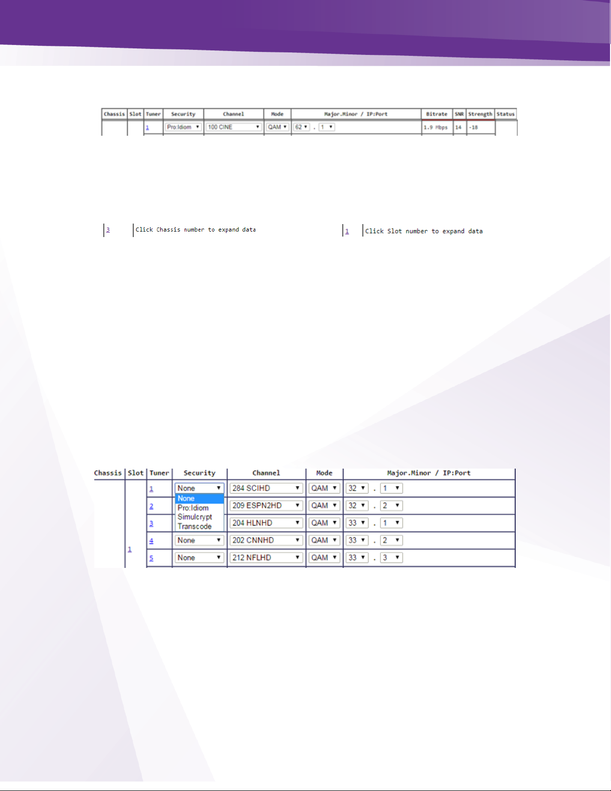
22.3 Channel Tuning Options
➢ The chassis and slot number hyperlinks in the Chassis and Slot columns allow you to collapse the
display for the selection so that multiple cards and chassis can be more easily displayed.
Chassis number hyperlink
Slot number hyperlink
➢ Tuner number hyperlink will navigate to the COM51 advanced edit page
Security - Figure 25 shows the Security column dropdown which allows you to apply any of the
supported security modes to the associated channel.
Options are:
➢ None - This setting removes all DRM and will only function on standard definition channels.
Removal of Pro:Idiom Encryption from HD channels must be authorized by AT&T / DIRECTV .
➢ Pro:Idiom - This is the standard setting for HD, Pro:Idiom encrypted HD channels
➢ Transcode – Enables encryption to be approved 3
rd
party devices
➢ Simulcrypt – Samsung Lynk (not currently implemented)
Figure 25 – Encryption Settings
Page 43
w w w . t e c h n i c o l o r . c o m / m c s
Page 43
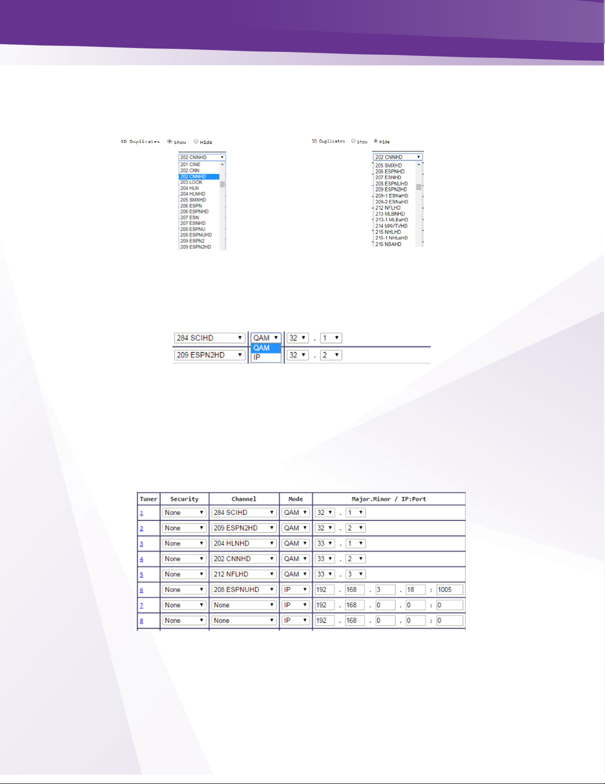
Channel - Figure 26 shows the Channel dropdown feature. This allows you to assign a tuner to any
channel in the guide data, including channels not authorized.
If SD Duplicates is selected both HD and
SD channels will display
If Hide SD duplicates is selected only the
HD channels will display
Figure 26 - Channel Selection Drop Down
Mode - Figure 27 shows the dropdown options for QAM and IP output modes.
Figure 27 - Output Mode
Major.Minor / IP:Port - Figure 28 below shows the Mode column. If QAM mode is selected this
field allows selection of the major and minor QAM channel.
➢ The dropdown menu will display channels programmed for QAM output.
➢ If IP mode is selected the field input is for the IP and port number assigned to each channel
Figure 28 - Major/Minor Ch or IP and Port Settings
Page 44

w w w . t e c h n i c o l o r . c o m / m c s
Page 44
Bitrate - Figure 29 shows the Bitrate field.
➢ Displays a snapshot of the bitrate at the QAM20 port associated with the selected QAM
major/minor channel. In the example QAM ch 33-2 is streaming 5.9 Mbps.
➢ If the stream is not routed to a COM20 card the Bitrate will read 0.0.
Figure 29 - Bitrate Display
SNR and Strength - Figure 30 shows the SNR and Signal Strength Display.
➢ The signal to noise ratio for the tuned channel. If the SNR is 10 or below, the block will be
highlighted yellow.
➢ Strength displays the relative signal strength for the tuned channel in dBm. If the strength is -
50dBm or below the block will highlighted yellow.
Figure 30 - SNR and Signal Strength
Page 45
w w w . t e c h n i c o l o r . c o m / m c s
Page 45
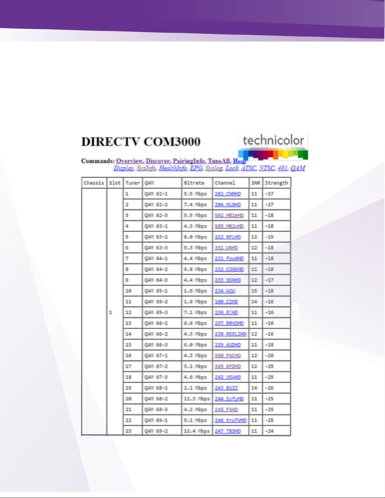
23 Discover Page
Most configurations on the COM3000 system can be done via the Overview page previously
discussed. However, there is redundant information in the Discover page and links to advanced edit
pages for feature configurations and troubleshooting.
➢ The COM51 card issues a discovery call for all other COM51 (and COM46) cards in the system and
populates a table with basic information on current tuning parameters and RF signal levels.
➢ Once this information is complete the Discover Web Page, showed in Figure 31 is displayed.
Figure 31 - COM51 Discover Page
Page 46

w w w . t e c h n i c o l o r . c o m / m c s
Page 46
23.1 Explanation of Discover Page Fields
Chassis - This field reports a unique identifier for the chassis.
➢ In systems that contain multiple chassis, this can be used to identify each chassis in the system.
➢ See Section 4.1 on how to assign unique identifiers to multiple chassis within a system.
Slot - This field identifies the card’s location within a chassis, numbered 1 through 6.
➢ If this field is grey, the slot number is a link to messages in the CAM Log.
Tuner - There are twenty-three entries per card for this column.
➢ The COM51 will display 23 tuners regardless of licensed tuner count. Refer to section 21 COM51
Tuner Licensing.
QAM or IP Address - If some of the programs are streaming to a QAM20, then “QAM” is
displayed as the column header.
➢ Signals are routed out of the system, then “IP Address” will display as the column header.
➢ If the card is sending video to a QAM20, this field shows a snapshot of the output QAM channel
and QAM sub-channel number.
➢ If a card is streaming video to outside of the chassis, this field will contain the destination IP
address. Both unicast and multicast addresses are supported.
Bitrate or Port - If some of the programs are streaming to a QAM20, then “Bitrate” is displayed as
the column header.
➢ If streams are routed out of the system, then “Port” will display as the column header instead.
➢ If the card is sending video to a QAM20, this field shows the instantaneous bitrate of the channels
being sent out of the QAM20. Otherwise this field contains the destination port associated with
the destination IP address described above. You must have a unique IP and or port number for
each individual channel you wish to stream.
Channel - This field shows the name and the AT&T / DIRECTV channel number tuned.
➢ Field is also a link that permits the user to change channels.
➢ If the card has not been authorized or paired, then the channel will be highlighted in red.
Page 47

w w w . t e c h n i c o l o r . c o m / m c s
Page 47
SNR - This field returns the Signal-to-Noise Ratio associated with the selected tuners.
➢ SNR should be >11
➢ Low SNR (<11 >8) results in a yellow highlight
➢ Very low SNR (<8) results in a red highlight
Strength - This value provides a value corresponding to the internal Automatic Gain Control
setting in the COM51.
➢ For optimum performance of the COM3000, this value should be somewhere between -25 and -55.
➢ If the Strength is low, it will be highlighted in yellow and if the Strength is very low, it will be
highlighted in red.
Page 48

© 2012 Technicolor. All Rights reserved
24 Advanced Edit
Advanced edit pages are accessed either by clicking on the tuner number from the COM51
Overview page or by clicking on the DIRECTV channel number from the Discover screen.
24.1 The Basic Channel Tune Screen
The first section of the Advanced Edit page is the Channel Tune screen shown in Figure 32.
Figure 32 - COM51 Basic Tune Screen
➢ This page permits two different ways of tuning AT&T / DIRECTV channels with Pro: Idiom
encryption.
➢ Specifies the destination IP address and port along with the AT&T / DIRECTV channel number.
➢ Allows entry of a QAM channel, sub-channel and AT&T / DIRECTV channel number. This is
redundant to the channel tuning on the Overview screen.
➢ Channels entered in this screen will tune to HD programming. This can be helpful when tuning
local channels not easily identified as High Definition
Page 49

w w w . t e c h n i c o l o r . c o m / m c s
Page 49
24.2 Advanced Tune
The Advanced Tune page can be used to change the main tuning parameters of a channel.
Additional parameters can be accessed by clicking the Advanced Edit hyperlink at the bottom of
the Basic Tune screen, which navigates to the Advanced Tune screen shown below in Figure 33.
Information identifying the chassis / slot / tuner and card IP address currently being addressed is
displayed at the top of the page below the command links.
Chassis - This value shows the Chassis number of the COM400 that holds the COM51 card you
are currently tuning.
Slot - This value shows the Slot number within the COM400 chassis that holds the COM51 card
you are currently tuning.
Tuner - This value indicates which tuner on the COM51 card you are controlling.
IP - This field shows the IP address of the COM51 card you are currently interacting with.
Figure 33 - Advanced Tune Screen
Most configurations in the advanced edit page are redundant to settings entered from the
Overview page of the COM51 UI.
A detailed description of each advanced tuning field on the Advanced Edit page follows:
Dest_IP_Address - In this field, you will enter the IP address of the device you wish to
stream video content to (e.g. an edge QAM).
➢ The COM51 will stream to any valid unicast or multicast address.
Page 50

w w w . t e c h n i c o l o r . c o m / m c s
Page 50
Dest_Port_Number - This field represents the destination port of the IP address you wish to
stream to.
Protocol_Type - This field is used to control whether the COM51 streams the data in UDP
or RTP packet structures. The default value is UDP.
Channel_Object_ID - This field is the data that the COM51 uses for tuning purposes.
➢ It will be automatically filled in when a valid AT&T / DIRECTV channel number is entered in
the “Major_Number” field.
➢ Before the card has been successfully tuned, the default value is 0.
Major_Number - This field is equivalent to the AT&T / DIRECTV channel number you
tune to on a typical AT&T / DIRECTV tuner.
The default value is 0.
Minor_Number - This field is automatically filled in by the COM51 card, with a default
value of 65535.
➢ If the AT&T / DIRECTV channel has a minor channel number then the Minor_Number value
must be entered.
➢ Many AT&T / DIRECTV channels have both high-definition and standard-definition channels
with the same Major and Minor numbers. The COM51 will default to the high-definition
channels when tuned from this field. To set the standard-definition channels instead, add
100000 to the Minor_Number. In most cases, this would cause the Minor_Number to be
165535 if the standard-definition channel is desired.
High-definition Minor_Number (default)
Standard-definition Minor_Number (add 100000)
Page 51

w w w . t e c h n i c o l o r . c o m / m c s
Page 51
Stream_ID - This field is optional and allows a unique identifier to be applied to every video
stream produced by the COM3000 system.
➢ The allowable values for this field are any whole number between 1 and 65535. This field is
to be left as default for normal operation.
o To enable a second audio stream set the Stream_ID to 54000.
Page 52

w w w . t e c h n i c o l o r . c o m / m c s
Page 52
Security_Mode - Typically, this field will not need to be changed. The only settings most should
be concerned with are:
➢ None - Setting will only work on AT&T / DIRECTV channel 100. This allows you to turn Pro:
Idiom encryption off so that a standard HDTV or PC-based utility like VLC Media Player can
be used for troubleshooting.
➢ Pro_Idiom – This is the standard setting for HD Pro:Idiom encrypted channels.
Persistent - Setting this value to ‘1’ tells the COM51 to retain all channel and IP-destination
settings in memory (i.e., data entered into the card is “persistent”).
➢ Eliminates the need to reprogram the COM51 cards after every power-cycle or reboot.
➢ Persistent is on by default (i.e., 1). It should be on for most installations. Otherwise, all
settings will be lost in the event of a power interruption.
Page 53

w w w . t e c h n i c o l o r . c o m / m c s
Page 53
24.3 Informational Status
The Info section, shown below in Figure 34, provides a view of many key indicators to the
operation of the COM51 card.
➢ A concise index to the characteristics of each individual COM51 card according to its
status and user-defined settings..
Figure 34 - "Info" Section of the Advanced Edit Page
Following is a brief explanation of each field shown above:
Chassis_ID - This field represents which COM400 chassis the card resides in when there are
multiple chassis in the system.
Slot_ID - This field identifies the card’s location within a chassis, numbered 1 through 6.
Tuner - This field identifies the tuner’s location on the COM51 card (1 through 23).
Card_IP - This field shows the IP address of the COM51 card
Receiver ID - This field reports the AT&T / DIRECTV Receiver ID, or RID. This value is
the first of two parameters required to obtain authorization on the AT&T / DIRECTV
network.
CAM_ID - This field reports the AT&T / DIRECTV CAM ID. This value is the second of
the two parameters required to obtain authorization on the AT&T / DIRECTV network.
Network_ID - This field displays the AT&T / DIRECTV network of the currently tuned
channel. This number correlates to a specific satellite and can be used in conjunction with the
Frequency Index” field below to determine whether the card is locked to the correct channel.
Frequency_Index - This field reports the frequency index corresponding to the channel the
tuner is currently set to. Frequency_Index is a 0-base value. Transponder #s on meters and
IRD are 1 base. To determine the channel’s transponder, add 1 to the Frequency Index.
Page 54

w w w . t e c h n i c o l o r . c o m / m c s
Page 54
The table below in Figure 35 details the Network_ID numbers and corresponding satellite.
Network_ ID
Satellite
0
101
2
110
3
119
10-11
99
14-15
103
In the example below, we are looking at CNN HD:
Network ID = 10
Satellite 99
Frequency Index= 17 +1
Transponder 18
Authorized - This field provides feedback on whether the card has been authorized within
the AT&T / DIRECTV network. The card needs to be paired and authorized to receive
AT&T / DIRECTV programming. A value of ‘1’ means that the card has been
successfully authorized; ‘0’ means that it has not yet been authorized or has lost its
authorization.
Paired - This field provides feedback on whether the smart card has been successfully
paired with the COM51 card. The card needs to be paired and authorized to receive AT&T /
DIRECTV programming. A value of ‘1’ means that the card has been successfully paired;
‘0’ means that it has not yet been paired or has lost its pairing.
Figure 35 - Network ID and Frequency Index
Page 55

w w w . t e c h n i c o l o r . c o m / m c s
Page 55
Blackout - This field can be used to determine whether AT&T / DIRECTV has issued a
blackout of the content on a channel. This is a good thing to investigate if the video
suddenly stops playing on any channel, but it is particularly likely to happen with
nationally televised sporting events. A value of ‘0’ means that the channel should be
functioning properly; ‘1’ means that the programming on the selected channel is not
currently available to you. TVs will display a blackout message on screen in the event of
a blackout.
SW_Version - This field reports the software version that currently resides on the COM51
card.
24.4 COM51 LED Control Feature
The information shown in Figure 36 below is one of the subsections available on the Advanced
Edit page.
Figure 36 - LED Control
This section gives you the ability to assume control of the PWR LED temporarily. This feature
can help you easily identify a specific card within a chassis if there is ever any doubt about
which card you are accessing. A brief explanation of each field shown above is as follows:
LED_State – This field allows you to control the PWR LED. This may be used as a simple
means to identify a particular card within a chassis at a remote location. The allowed values are:
0 = Off
1 = On
2 = Flashing
Page 56

w w w . t e c h n i c o l o r . c o m / m c s
Page 56
24.5 COM51 CAM Log Data
This section gives you the ability to read the log files generated by any COM51 card’s
Conditional Access Module (CAM), also known as its smart card. The messages reported here
match the ones that may be seen on a normal set-top box and can be used to determine whether
the card has been properly authorized and paired.
Figure 37 - CAM Log Interface
Under normal circumstances, an authorized card will produce a very short CAM log file
with 0 0 0: CARD_INSERTED displa yed.
If, however, there are issues with the card’s authorization, you will see messages that look more
like this:
The 3-digit values starting with a “7” are the AT&T / DIRECTV support extension numbers
associated with the error condition.
Refresh - Refreshes this display.
Clear_CAM_Log - Clears all current entries in that card’s CAM log.
Figure 38 - Cam Log Report
Page 57

w w w . t e c h n i c o l o r . c o m / m c s
Page 57
24.6 COM51 Software Reset
This section allows you to initiate software reset on the card identified in the “CardIP” field.
➢ Activating this feature is the equivalent to pushing the recessed reset button on the face of
the COM51card and has a similar effect as pressing the small reset button on a traditional
set-top box.
Figure 39 - Reset Interface
24.7 COM51 File Transfer Utility
Similar in function to the upgrade section found on the PairingInfo page, this section provides
you with a method of transferring software updates and license files to or transferring log data
from individual COM51 cards. See Section 11 for more information on upgrading your COM51
cards.
Figure 40 - File Transfer Interface
Following is a brief explanation of each field shown above:
Usage - This field is used to tell the COM51 which type of transfer to execute. Only four values
are available for customer use (all others are for development purposes only):
1 = MT – This option allows you to upload the special MediaTune authorization and
channel guide files. See COM3000 Technical Support - Mediatune Installation Folder on
the Technicolor / MCS website for details.
2 = Software Upgrade – This option is used to update the COM51 software. In this case,
the file is downloaded to the COM51 card displayed in the browser’s URL field.
3 = Log – This option tells the COM51 to transfer its log file to the destination entered in
the “IP_Address” field (i.e., log file is uploaded to PC).
4=License – This option uploads the XML license file that enables advanced features on
the COM51 such as the HD upgrade for the COM51-A.
Options above 5 & 6 are not enabled for field use.
Server_IP_Address - This field tells the COM51 card where to retrieve the software update or
license file or where to send the log file, based upon the “Usage” setting above. The default
value for this field is 192.168.1.254.
Page 58
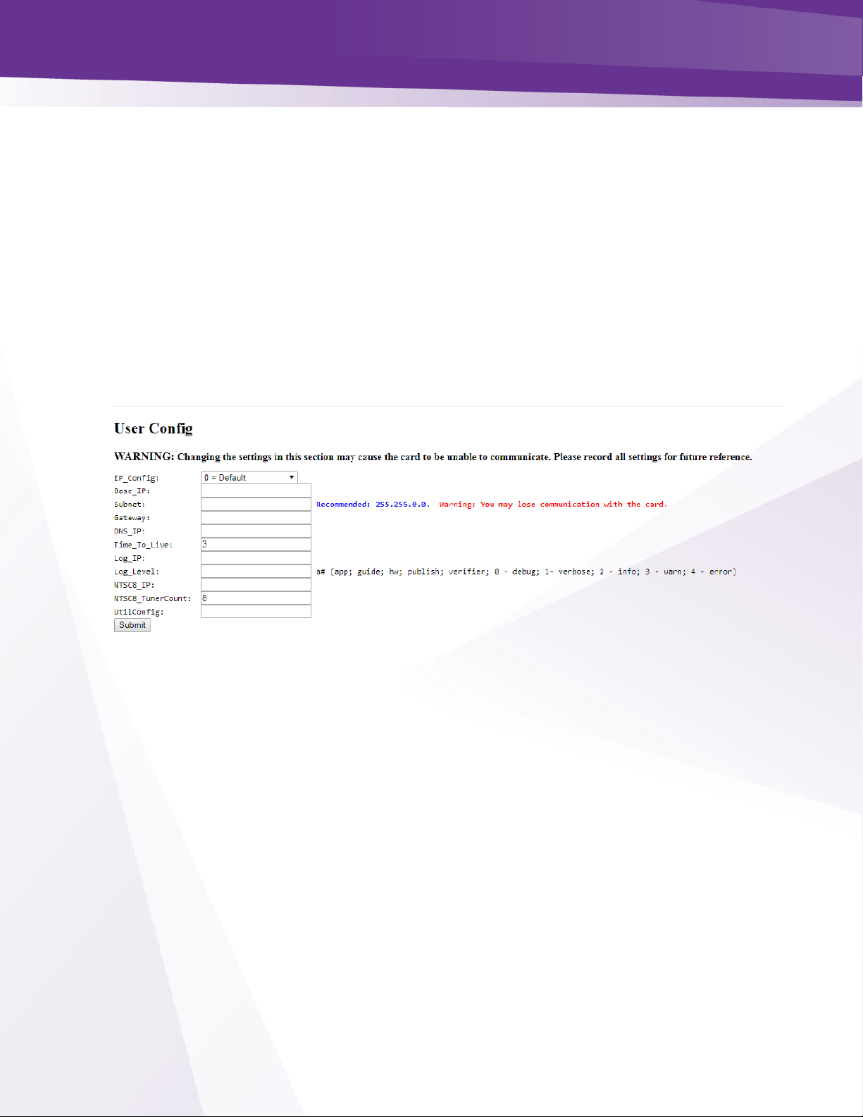
w w w . t e c h n i c o l o r . c o m / m c s
Page 58
Filename - This value entered in this field tells the COM51 which file to download (in the case
of software updates and license files), or what name you want to give the log file being
transferred from the card.
Mode – Must be set for TFTP
24.8 COM51 User Configuration Options
This section gives you the ability to customize select features of the COM51 cards to better suit
your application.
➢ Change IP settings the card
➢ Control and configure Syslog server
➢ Enter IP address of NTSC-8 and Tuner Count
Figure 41 - User Config Interface
Following is a brief explanation of each field shown above:
IP_Config - This field allows for one of 3 methods of IP address assignments to be chosen.
The default IP_Config setting is 0. Which sets the card one in chassis one to 192.168.3.18.
See Section 17.2 Setting up Multiple Chassis.
0 = Default - In this mode the IP address is assigned to the card based on the chassis ID
and slot the card is currently in. The formula for this address is 192.168.3.[1 + (chassis
ID X 16) + slot number]
In the default IP mode the Base_IP and the Gateway fields are ignored. The Subnet field
is also ignored but the Subnet mask is set to 255.255.0.0 and is applied.
1 = DHCP_Persistent - In this mode all IP address information Base_IP, Subnet and
Gateway are taken from the DHCP lease that the DHCP server issues to the card and is
stored in non-volatile memory.
Page 59

w w w . t e c h n i c o l o r . c o m / m c s
Page 59
4 = Fixed - In this mode the user sets the Base_IP, Subnet and Gateway fields. All fields
MUST be set. A Gateway MUST be defined regardless of it being there or not for this
mode. Once you set the card IP you must reboot the card.
8 = No Change - This setting does not actually represent a separate mode, but rather acts
as a way to tell the COM51 card that you would like it to continue using whatever mode
it is currently using.
Base_IP - In the Default mode this field will display the IP address of the card. In the
DHCP_Persistent mode this field will display the last address stored in non-volatile memory.
In the Fixed mode this field is where you would enter the IP address you wish to assign to
that card.
Subnet - This field allows you to give a subnet mask of your choosing to the COM51 card.
➢ This field is only applied in the Fixed mode.
Gateway - This field allows you to set a default gateway of your choosing for the COM51
card.
➢ This field is only applied in the Fixed mode and must be set when using that mode.
Time-to-Live - Time to Live field in IP protocol header.
Log_IP - This field allows you to direct the COM51 card to send its log files to an external
destination automatically.
➢ This is very useful for monitoring the health of the system over an extended period.
➢ After entering the IP address of the destination, the log files will start being forwarded to this
address after a short delay.
➢ You may then run a system-logging utility like Kiwi or TFTP32 on the destination computer to
capture this information. Once the Log IP is set you must reboot the card.
Log_Level - This field allows you to define the level of detail that will be captured in the
resulting log files.
➢ Due to the complexity of this setting, it is strongly advised that it be left blank unless someone
from support has asked to change the value.
Page 60

w w w . t e c h n i c o l o r . c o m / m c s
Page 60
NTSC-8_IP – Enter the IP address of a NTSC-8 to be fed from this COM51 card.
NTSC-8_tunercount – COM51 cards will stream 1-23 tuners to NTSC-8.
➢ Enter the number of tuners you are using for NTSC-8s. One COM51 card will stream 23 channels
and a program guide to NTCS-8. (see NTSC-8 integrators manual)
UtilConfig - This field is for development purposes only, and should be left blank unless you
have been asked to modify the value by someone from technical support.
Page 61
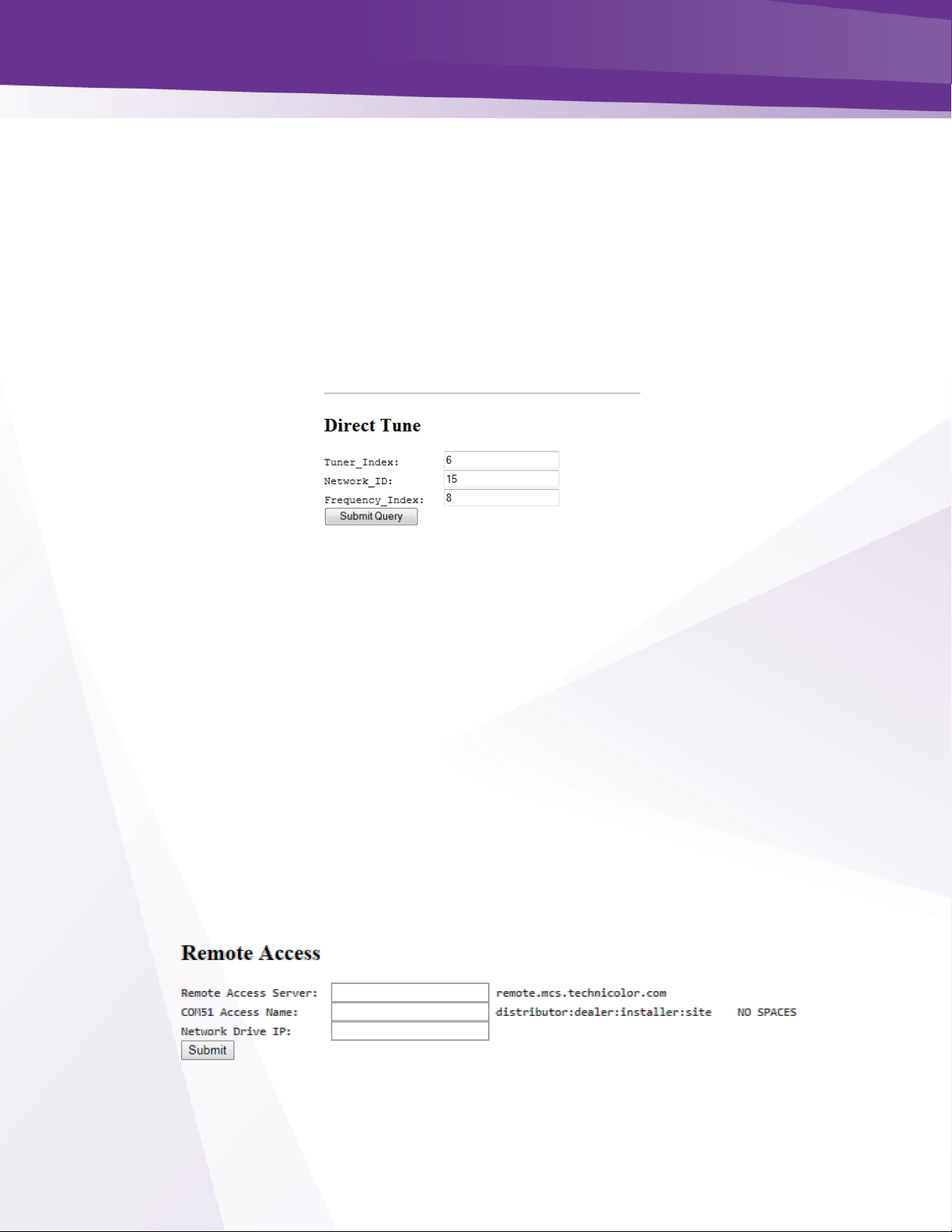
w w w . t e c h n i c o l o r . c o m / m c s
Page 61
24.9 COM51 “Direct Tune” Feature
The information shown in Figure 42 below is one of the subsections available on the Advanced
Edit page.
➢ This section gives you a method to force a tuner to a satellite and transponder pair.
➢ This can be useful when attempting to track and isolate RF problems with the COM3000 system.
The data required to perform this operation can be gathered from the basic “Tune” interface
shown in the advanced tune section (see Figure 33 - Advanced Tune Screen )
➢ A brief explanation of each field follows:
Figure 42 - Direct Tune Interface
Tuner_Index - This field allows you to direct an individual tuner to tune to a specific network
ID and Frequency_Index.
Network_ID - This field displays the AT&T / DIRECTV network of the currently tuned
channel. This number correlates to a specific satellite and can be used in conjunction with the
“Frequency_Index” field below to determine whether the card is locked to the correct channel
version.
Frequency_Index - This field displays the AT&T / DIRECTV frequency index of the
currently tuned channel. This number correlates to a specific transponder and can be used in
conjunction with the “Network_ID” field above to determine whether the card is locked to the
correct channel.
24.10 Remote Access Feature
Currently not supported.
Figure 43 - Remote Access Feature
Page 62
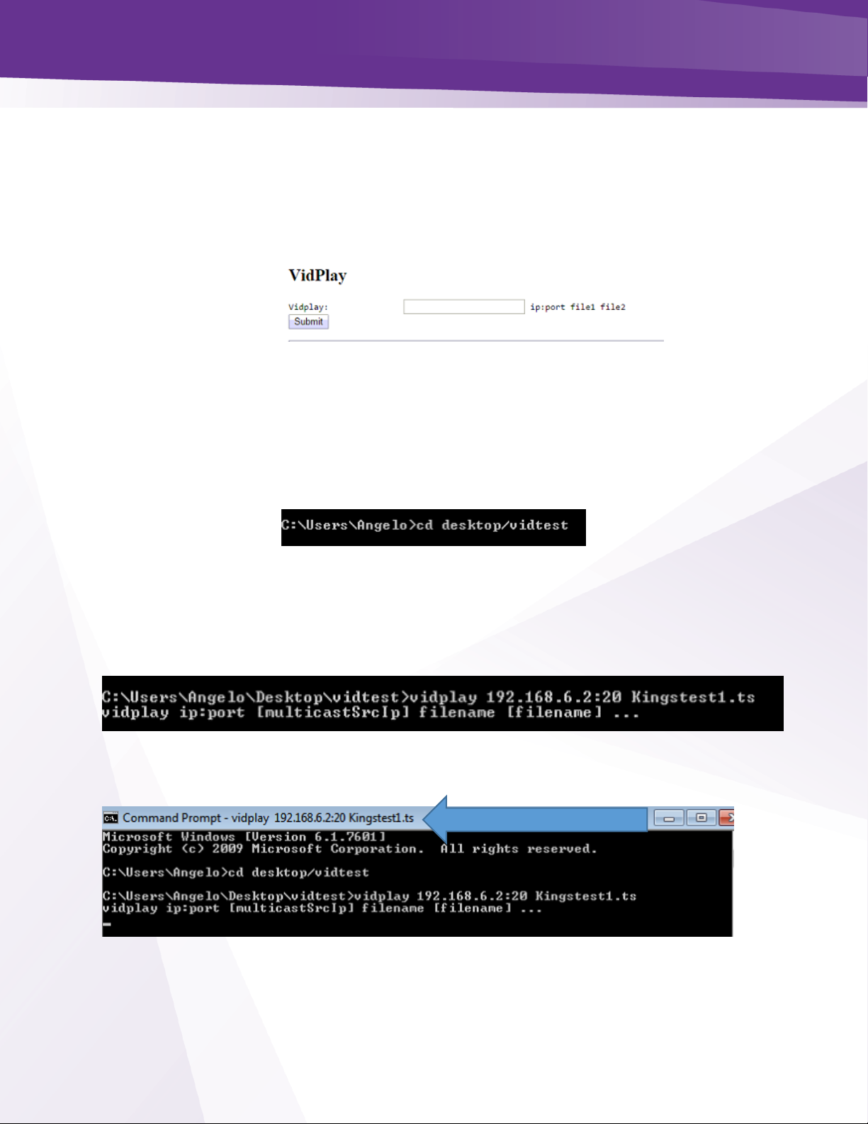
w w w . t e c h n i c o l o r . c o m / m c s
Page 62
24.11 Using the VidPlay Feature
The VidPlay Feature is no longer available due to changes in the Western Digital My Cloud
NAS drive software. It is recommended to use an inexpensive PC and VIDplay.exe software
provided by Technicolor.
Figure 44 - Vid Play
24.12 Setup for Vidplay.exe
➢ Create a folder on your PC desktop named vidtest.
➢ Save vidplay.exe file and the video file in the folder.
➢ To play the video open a dos prompt and enter cd desktop/vidtest
➢ At the vidtest prompt enter type vidplay QAMIP:port filename
➢ Example: vidplay 192.168.6.2:20 Kingstest1.ts
➢ When the exe runs you will see the information at the top of the dos shell window.
QAM IP:port and filename
Page 63

w w w . t e c h n i c o l o r . c o m / m c s
Page 63
➢ Navigate the COM3000 QAM tab and verify it is streaming to the QAM
➢ In this case the video will play on ch 23-4
➢ The video will continue to play in a loop until the DOS window is closed.
Port 20
Page 64

w w w . t e c h n i c o l o r . c o m / m c s
Page 64
24.13 Using the COM51 “Simulcrypt” Feature
Simulcrypt is not currently supported on COM51.
➢ To facilitate LYNK or other 3
rd
party DRMs submit a request to DIRECTV to disable Pro:Idiom
encryption.
24.14 Displaying COM3000 Status
By clicking the Display hyperlink at the top of any COM3000 web interface page, you can see
the information last displayed on the Discover Screen
.
Page 65
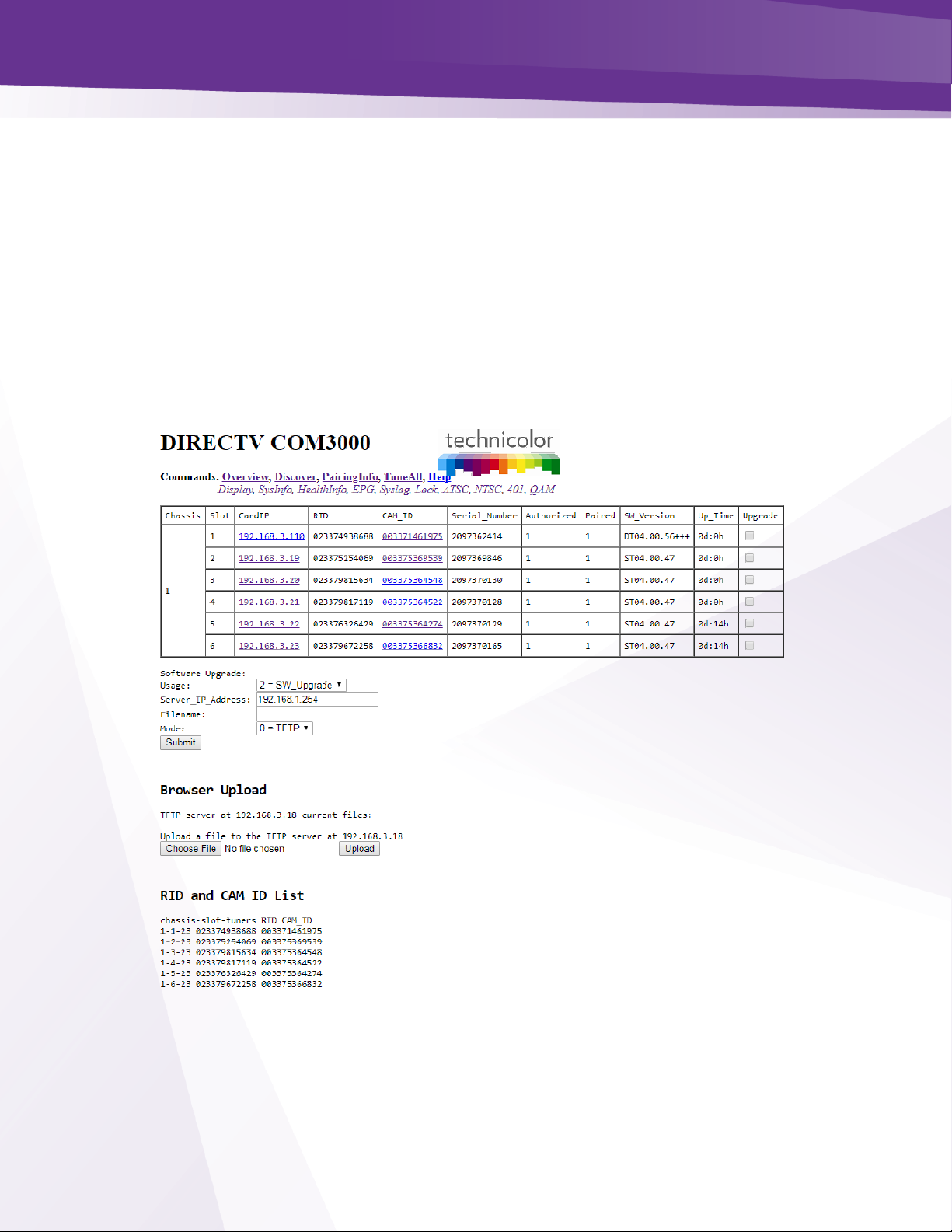
w w w . t e c h n i c o l o r . c o m / m c s
Page 65
25 Pairing Info
By clicking the PairingInfo hyperlink at the top of any COM3000 web interface page, you
can quickly evaluate the authorization status of all cards in the system.
➢ In the example shown in Figure 45, all cards are activated and paired
➢ Card one has received a DHCP address of 192.168.3.110. It is still assessable at the default
192.168.3.18 address.
➢ This page also provides direct access to a card’s internal syslog and CAM log and the ability to
upgrade multiple cards.
➢ These can be reached by clicking the hyperlinks that represent the card’s IP address and
CAM_ID, as can be seen below in Figure 45.
Figure 45 - COM3000 Pairing Info Page
Page 66

w w w . t e c h n i c o l o r . c o m / m c s
Page 66
Following is a detailed list of information available on the PairingInfo page.
Chassis - This field reports a unique identifier for the chassis. In systems that contain multiple
chassis, this can be used to identify each card in the system.
➢ See Section 4.1 on how to assign unique identifiers to multiple chassis within a system.
Slot - This field identifies the card’s location within a chassis, numbered 1 through 6.
CardIP - This field shows the IP address of the COM51 card that resides in the chassis and slot
combination to its left. If the system is connected to a network providing DHCP the issued IP
address will be displayed.
➢ This field is also a link to see the Syslog for that card.
RID - This field reports the AT&T / DIRECTV Receiver ID, or RID. This value is the first of
two parameters required to obtain authorization on the AT&T / DIRECTV network.
CAM_ID - This field reports the AT&T / DIRECTV CAM ID. This value is the second
parameter required to obtain authorization on the AT&T / DIRECTV network.
➢ You can click on the hyperlink in this column to be taken directly to that card’s CAM Log (see
Section 6.2.4 for more information on reading a card’s CAM log).
Serial_Number – This field contains the unique electronic serial number of the board assigned
at the time of manufacture.
Authorized – This field reports whether the COM51 card’s CAM has been authorized.
➢ A value of ‘1’ indicates that the card has been authorized, thereby enabling the card to receive
AT&T / DIRECTV programming.
➢ A value of ‘0’ indicates that the card has not been authorized.
Paired – This field reports the pairing status of the CAM card.
➢ In order to be capable of receiving an authorization to the AT&T / DIRECTV network, the RID
and CAM data must first be paired.
➢ If this has not happened, then the card cannot be authorized until the pairing is resolved.
➢ A value of ‘1’ indicates that the RID and CAM are successfully paired; a value of ‘0’ indicates that
they are not.
SW_Version – This field reports the software version that currently resides on the COM51 card.
Page 67

w w w . t e c h n i c o l o r . c o m / m c s
Page 67
Up_Time – This field gives an indication of how much time has elapsed since the card was last
rebooted or powered up.
Upgrade – By checking this box for a particular card, you will make each of the fields at the
bottom of the screen active for that card. This allows you to upgrade multiple cards at a time.
Figure 46 below shows in detail the upgrade section available on the PairingInfo page.
Following is a brief description of the relevant fields on this page:
Usage - This field allows you to select which type of file transfer you wish to undertake for a
particular card. The available options are shown below. It should be noted that when selecting
any option other than ‘2’, the card will appear to go through the usual software update cycle, but
that it will revert to the current build of code once it has rebooted.
0 = Set_Log_IP – This option allows you to identify the IP address to which you wish to
send COM51 logging for monitoring by a syslog utility.
1= MT – This option allows upload of Mediatune channel files.
2= SW_Upgrade – This is one of two means of updating the software in a COM51 card.
3= Log – This option allows you to copy a COM51 card’s internal log files to a PC.
Figure 46 - COM46 Multi Card Upgrade
Page 68

w w w . t e c h n i c o l o r . c o m / m c s
Page 68
4= License – This option allows you to load various software licenses to enable new
modes and features in the COM51. One example might be upgrading the COM51-A to
HD mode after purchasing software license upgrade from Distributor
7 = KeyRenewal – This option will send a Pro:Idiom key renewal to any TV tuned to a
RF channel on the card selected.
Note: Options 5 AND 6 are not available to users and are for development purposes only.
Server_IP Address - This field gives the IP address of the server from which Filename: will be
uploaded. When doing a Mode 2 upgrade, this field can be the address of another COM51 card
to which a SW update has already been uploaded. See the Browser Upload description and
Section 7 for details.
Filename - The name of the SW update binary or license file to upload.
Browser Upload - To eliminate the need for a 3rd party TFTP server, a COM51 acts as a TFTP
server for other cards in the system.
➢ The Browser Upload field allows you to upload the selected file to the card whose IP address is
shown below the Browser Upload heading from the web interface.
➢ The Choose File and Upload buttons are used to find and upload the desired file(s) from the
browser.
Page 69

w w w . t e c h n i c o l o r . c o m / m c s
Page 69
26 Tune All
The information shown in Figure 47 below is the result of clicking the TuneAll hyperlink at the
top of the COM3000 web interface page.
➢ This section provides a practical way to configure an entire COM3000 system with minimal
effort.
➢ In order to use this feature, start by copying and pasting the information provided at the bottom
of the browser page (below the Submit button) either directly into the text field provided or into
your text editor of choice, and then modifying it as indicated by the instructional comments
located above the text field.
Figure 47 - COM51 Tune All
Instructions
Page 70

w w w . t e c h n i c o l o r . c o m / m c s
Page 70
The text in the tuning table take the following form (see Section 1.1 for more on tuning):
➢ Chassis-Slot-Tuner, IP_Address:Port_Number, Major_Number-Minor_Number-Security_Mode;
➢ The sample line below indicates the 1st tuner of a card residing in Slot #4 of Chassis #2. It is
targeting Port 301 of the device residing at the IP address 192.168.4.245 and tuned to the HD
broadcast of channel 242 with Pro:Idiom encryption set.
2-4-1, 192.168.4.245:301, 242-65535-1;
➢ Upon initial system startup, your table might look something like this:
Current Tuning Table
1-1-1, 192.168.0.0:0, 0-0-0;
1-1-2, 192.168.0.0:0, 0-0-0;
1-1-3, 192.168.0.0:0, 0-0-0;
1-1-4, 192.168.0.0:0, 0-0-0;
1-1-5, 192.168.0.0:0, 0-0-0;
1-1-6, 192.168.0.0:0, 0-0-0;
1-1-7, 192.168.0.0:0, 0-0-0;
1-1-8, 192.168.0.0:0, 0-0-0;
➢ After modifying the data to meet your system needs, it might look like this:
Current Tuning Table
1-1-1, 192.168.4.245:6401, 3-65535-1;
1-1-2, 192.168.4.245:6402, 10-65535-1;
1-1-3, 192.168.4.245:6403, 29-65535-1;
1-1-4, 192.168.4.245:6657, 6-65535-1;
1-1-5, 192.168.4.245:6658, 17-65535-1;
1-1-6, 192.168.4.245:6659, 259-65535-1;
1-1-7, 192.168.4.245:6913, 209-65535-1;
1-1-8, 192.168.4.245:6914, 276-65535-1;
➢ After editing the tuning table, copy and paste this information into the field in the TuneAll
command page and then click Submit.
➢ Saving a copy of the tuning table for your entire system in the form of a text file is
recommended.
Page 71

w w w . t e c h n i c o l o r . c o m / m c s
Page 71
27 Help
The Help tab provided a short reminder of the functions of each tab on the COM51 user interface
as shown below in Figure 48.
Figure 48 - Help Tab
28 SysInfo
The Sysinfo tab shown below in Figure 49 provides important information about the COM51
status.
➢ This table identifies feature sets licensed for each COM51 card in the system.
Figure 49 - COM51 Sys Info Page
Following is a detailed list of the information available on the SysInfo (System Info) page.
➢ Chassis - This field reports a unique identifier for the chassis. In systems that contain multiple
chassis, this can be used to identify each card in the system.
➢ Slot – This field identifies the card’s location within a chassis, numbered 1 through 6.
➢ CardIP _ This field shows the IP address of the COM51 card that resides in the chassis and slot
combination to its left. If the COM51 has obtained an IP address from an external DHCP server
that IP will be displayed as shown in Figure 49.
➢ EPG - This field shows whether the card identified is generating EPG data.
➢ MAC_Address This value is loaded during the manufacturing process and is unique to every
COM51 card. Every IP-enabled device contains a similar address, which is used to ensure that all
Ethernet traffic is routed to the correct destinations.
Page 72

w w w . t e c h n i c o l o r . c o m / m c s
Page 72
➢ Tuner Count – Displays the licensed number of tuners for each COM51. The first number
represents the licensed tuner count, the second is the number of available SWiM channels.
➢ Features – This field displays the licensed operational features for each card.
o HD - Streamout - The basic license configuration of all COM51 cards.
o MT – Mediatune
o IP - Licenses card for IP output in the absence of a QAM20
o Transcode – N/A
o Clear HD - Allows HD programming to be output in clear QAM (requires AT&T / DIRECTV
authorization)
o NTSC-8 – COM51 card is connected to a Technicolor NTSC-8 modulator.
o Monitored – COM3000 is connected to a REST server monitoring the health of the
system
29 HealthInfo
By clicking the HealthInfo hyperlink at the top of any COM3000 web interface page, you will
access the page shown below in Figure 50. The data available here gives you an indication of the
overall health of the COM3000 system and can be used to identify potential problem areas at a
glance.
Figure 50 - COM3000 Health Info Page
Following is a detailed list of the information available on the HealthInfo page.
➢ Chassis – This field reports a unique identifier for the chassis. In systems that contain multiple
chassis, this can be used to identify each card in the system.
➢ Slot – This field identifies the card’s location within a chassis.
➢ CardIP – This field shows the IP address of the COM51 card that resides in the chassis and slot
combination to its left.
➢ Card_Temperature – Reports internal temperature
➢ IC_Temperature – This field reports the internal temperature of the main processor chip on the
COM51 card. An elevated temperature here and nowhere else could mean that this chip is
defective.
➢ PS 0 & 1 Health – Deprecated. These fields will always report N/A in a COM51.
➢ Fan0 Health – This field reports the health for Fan 0. If the fan is connected and operating
properly, the value should return “OK”. If there is a problem the value will return “Fault”.
Page 73

w w w . t e c h n i c o l o r . c o m / m c s
Page 73
➢ Fan1 Health – This field reports the health for Fan 1. If the fan is connected and operating
properly, the value should return “OK”. If there is a problem the value will return “Fault”.
30 EPG
See Section 32 EPG Overview
Page 74
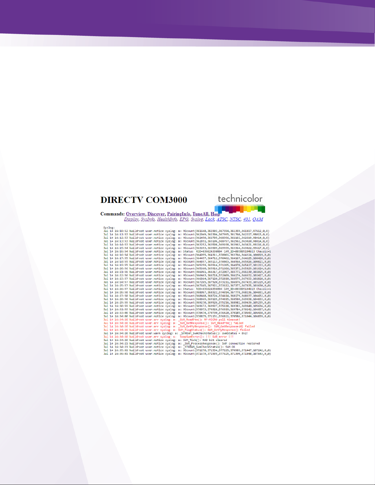
w w w . t e c h n i c o l o r . c o m / m c s
Page 74
31 Syslog
The system log file for the COM 3000 system records Simple Object Access Protocol (SOAP)
messages related to the performance of the cards.
➢ Much of the data in the logs is not relevant to the cards performance.
➢ To guide a system operator through the log entry interpretation Technicolor has changed key
log entry errors to red font.
➢ If you are experiencing problems with the COM3000 system a quick check of the SYSLOG can
alert you to problems. Contact your distributor or Technicolor support for further assistance.
The information shown below is the result of clicking the Syslog hyperlink at the top of any
COM3000 web interface page.
➢ Note that the syslog will only show the last 500 lines of messages from the card you are
currently logged into.
Figure 51 - Syslog Example
Figure 51 above shows a SWiM error occurred and cleared in less than two seconds.
In addition to clicking the Syslog hyperlink at the top of any COM3000 web interface page, the
syslog data may also be accessed directly from the PairingInfo screen by clicking directly on the
hyperlinks for each card’s IP address. Electronic Program Guide, PSIP and Guide.XML
Page 75
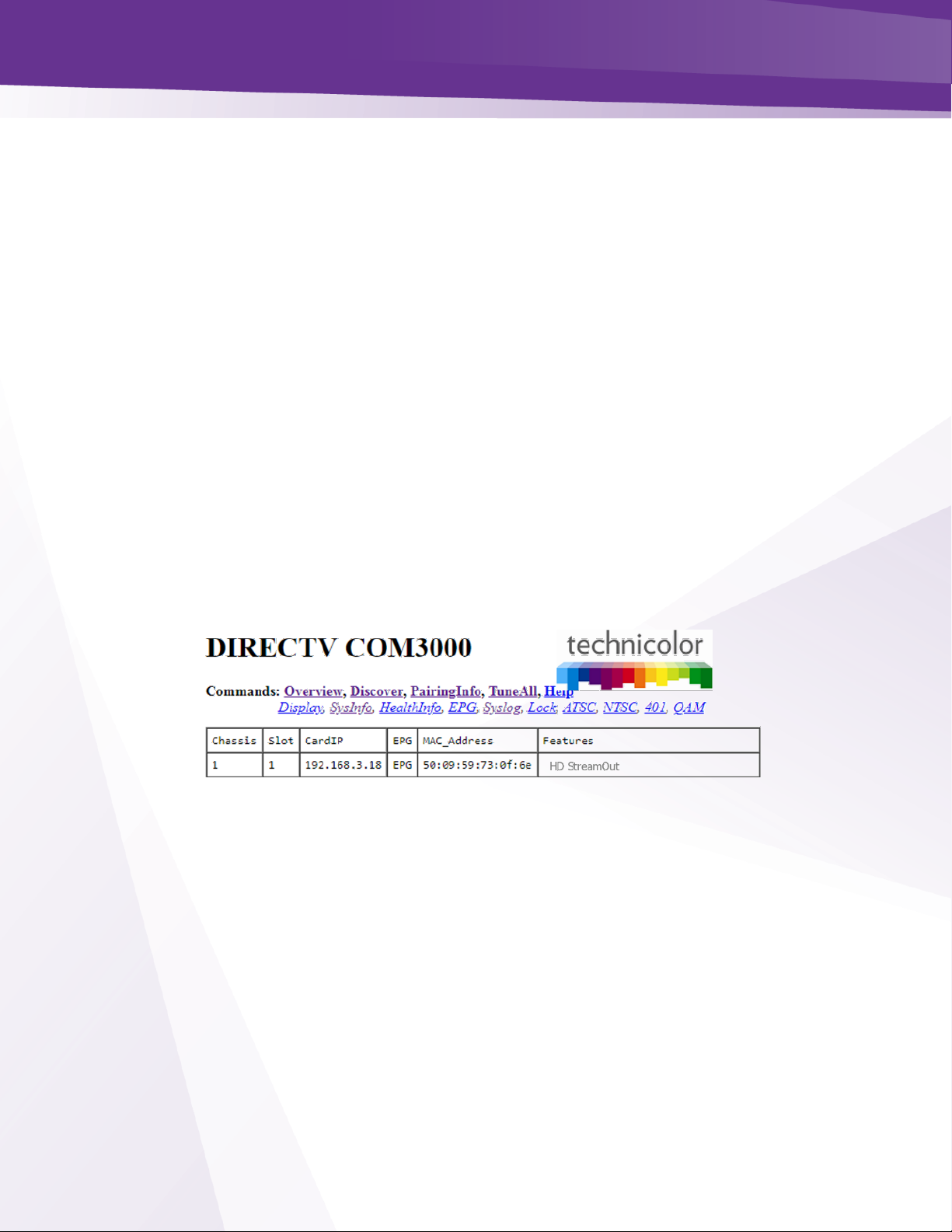
w w w . t e c h n i c o l o r . c o m / m c s
Page 75
32 EPG Overview
Each COM51 card gives you access to an integrated Electronic Program Guide (EPG) that can
be used to create a user-defined guide channel of all programming offered at your location.
➢ The EPG provides the viewer with an auto-scrolling channel listing. It is essentially a dynamic
MPEG video stream made up of still images of the current programming. It moves down the
list of assigned channels every 2.5 seconds, creating a constant cycle, showing nine channels
at a time. As such, the guide is not interactive, so the viewer must manually tune to their
channel of choice.
➢ Guide data includes
o All AT&T DIRECTV networks tuned on the system
o Channels from external sources.
➢ COM3000 EPG has the ability to store and stream welcome screen images to the QAM that will
play direct from the COM51 card.
o See section 33.1 for details on creation of Welcome Screen images.
➢ The basic EPG information is stored on the COM51 card. Therefor you will need to log into the IP
address of that card when setting up or editing the EPG file.
➢ The SysInfo page will display ‘EPG’ in the EPG field of a card utilized for this purpose. Figure 52
below shows an example of the SysInfo page displaying the EPG designation The EPG is running
on card one in chassis one. The card IP address is 192.168.3.18.
Figure 52 - SysInfo EPG
➢ If the number of channels in the EPG fits in one screen (nine or less) the channel listing will
not scroll. This permits the installer to have multiple cards generating a different EPG
channel listing nine channels each. This will create the user experience that channeling up or
down will page up or down nine channels in the guide.
➢ The EPG can also convert the AT&T / DIRECTV guide information into PSIP guide information
that is decodable by many televisions.
➢ PSIP permits the channel number to be remapped, the channel name can be displayed, the
current time displayed, and the current and next program titles displayed.
➢ To generate PSIP guide information, the last two numbers for each channel must list the
QAM20 chassis number and QAM20 destination port number. This information is
automatically filled in when EpgLoad is clicked. To disable PSIP guide generation for a
Page 76

w w w . t e c h n i c o l o r . c o m / m c s
Page 76
channel, set the port number to -1. If the DestIP is a valid IP address but the DestPort is 0,
then the EPG channel is disabled but PSIP guide generation is still enabled. This makes it
possible to have one card provide PSIP data and a separate card provide guide only.
➢ Different TVs may interpret and display PSIP data differently. It is recommended to test PSIP
operations prior to installation.
➢ It is possible to add non-AT&T / DIRECTV channels to the EPG. This is done by adding an entry
where instead of a AT&T / DIRECTV channel number, the capital letter ‘N’ appears followed by
the channel name, and program information separated by underscore characters.
o For example: 10-1 NLobby_The_Lobby_Channel 1 17
➢ Each channel in the EPG is comprised of a still image and it can take up to 10 seconds to
produce the image for every channel being offered when the EPG is first loaded. For
example, a location offering a list of 18 channels can expect to wait up to 3 minutes for a firsttime EPG configuration.
➢ Due to the combination of the auto-scroll programming and the constant addition of new
channels, you can expect the EPG to exhibit some odd behavior during the initial image
creation. It may appear to skip around at random, but it can be expected to settle back into
a normal operational state once it has finished generating all the necessary images.
➢ The EPG is a video-only channel, and you cannot set audio to play in the background.
Page 77
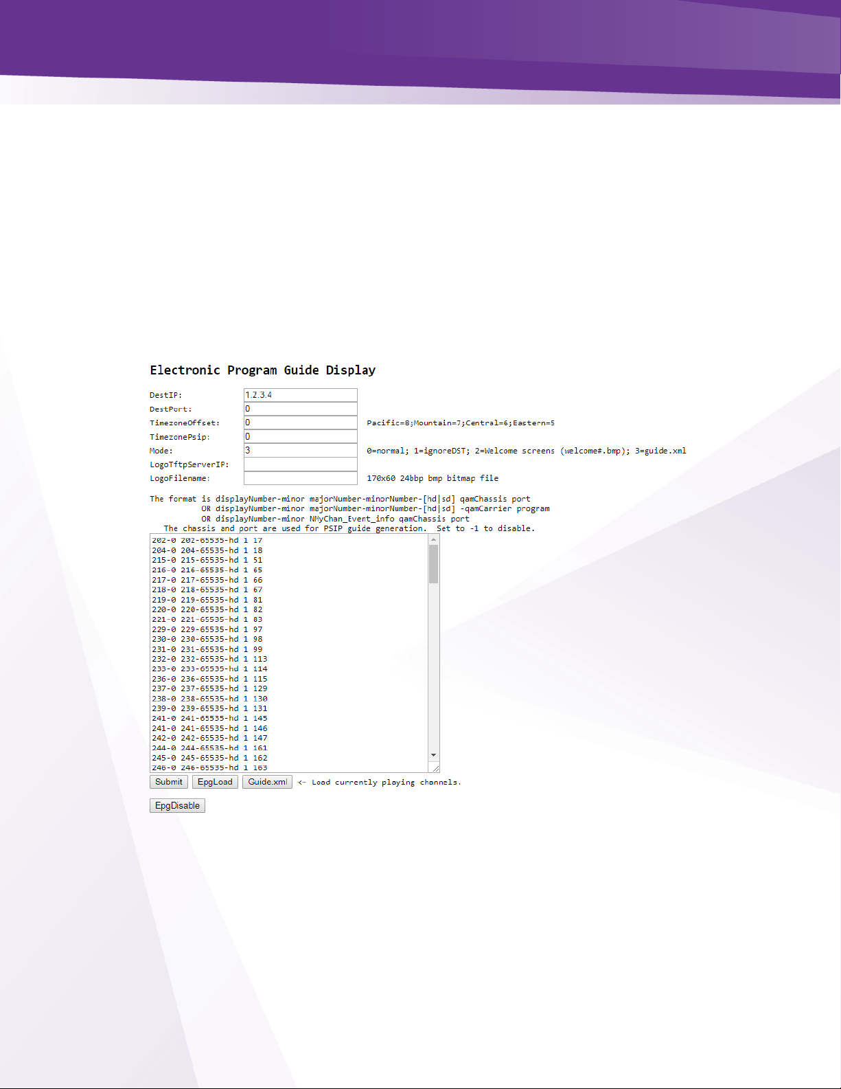
w w w . t e c h n i c o l o r . c o m / m c s
Page 77
32.1 Guide.XML Overview
Technicolor has developed an interactive guide feature that works exclusively with the
DCI401MCS set back box.
➢ DCI401MCS must be running software version 01.22.11 or newer.
Setup is similar to the instructions for EPG.
➢ Leave the IP field set to 1.2.3.4
➢ Click on Guide.XML to load and customize the guide as described in EPG Overview.
➢ Set the Mode to 3 as shown below in Figure 53:
Figure 53 - IPG Setup Page
Page 78

w w w . t e c h n i c o l o r . c o m / m c s
Page 78
32.2 Getting Started with EPG
Access the EPG setup screen shown in Figure 54 below, click the EPG
hyperlink at the top of any COM3000 web interface page.
Figure 54 - COM3000 EPG Page
Following is a brief explanation of each field available on the EPG page as shown above:
➢ DestIP - This field represents the IP address of the device you wish to send the EPG data to.
Typically, this will be the IP address of the QAM20 card you are going to use for the EPG
channel. Note: the default value of 0.0.0.0 can be entered at any time to disable the EPG
channel.
➢ DestPort - This field represents the port number that is to be used to map the EPG to a specific
QAM channel. The default value is 0.
Page 79

w w w . t e c h n i c o l o r . c o m / m c s
Page 79
➢ TimezoneOffset - This field is used to tell the COM51 to shift the guide data by the appropriate
amount of time to account for the property’s time zone. Example values can be seen to the
right of the field. The default value is 0.
➢ Time Zone PSIP - This field allows DCI401 boxes to align with TVs using PSIP. Most TVs have a
time zone setting, the DCI401 is based on GMT. Offset for GMT to synchronize a TV using a DCI
401 to a direct tuning TV. The same values are used as in the Time zone Offset field.
➢ IgnoreDST - This field is used to tell the COM51 to ignore Daylight Savings Time, if needed.
This is accomplished by entering a value of ‘1’ here. The default value is 0. If you are setting up
the Home screen feature set this field to 2.
➢ LogoTftpServerIP - This field is used to tell the COM51 where to find the custom logo for the
property. This will be the IP address of the PC containing the TFTP server.
➢ LogoFileName - This field is used to tell the COM51 the name of the file that is to be used for
the logo.
The EPG’s channel lineup is created in the large textbox on the lower half of the screen, using
the following format:
displayNumber majorNumber-[minorNumber]-[hd|sd] QAMchassis port
➢ DisplayNumber - This is the TV channel that the viewer will find the program on. majorNumber –
This is the same as the “Major_Number” field in the Channel Tune interface.
➢ minorNumber - This is the same as the “Minor_Number” field in the Channel Tune interface.
Please note that on submission, the EPG will default to ‘65535’ if this value is not provided.
➢ hd|sd - This tells the guide whether to pull the data for the HD or the SD version of a particular
channel. The default behavior for the COM3000 is to look for HD channels, so this setting allows
you to add SD channels to the EPG if needed. Please note that on submission, the EPG will
default to ‘hd’ if this value is not provided.
➢ QAMchassis - This tells the guide which chassis the QAM20 is in so that it knows the QAM20’s IP
address for sending PSIP guide data. If not using PSIP this field can be set to -1.
➢ Port – This tells the guide which QAM20 UDP port is being used for sending PSIP guide data. If
not using PSIP this field can be set to -1.
Examples:
10 501-65535-hd ➔ TV channel 10 carries HBOHD (from COM3000)
23 209-65535-hd ➔ TV channel 23 carries ESPN2HD (from COM3000)
45 202-65535-sd ➔ TV channel 45 carries CNN (from SMATV or COM3000)
37 8-65535-hd ➔ TV channel 37 carries local channel 8 (from OTA, SMATV, or COM3000)
2-1 NLocal_Program_Info 1 71 ➔ Non-AT&T / DIRECTV channel (channel name Local)
Note: The actual content could come from the COM3000, a separate SMATV system, or from
off-air, as long as the channel is available in AT&T / DIRECTV ’s lineup.
Page 80

w w w . t e c h n i c o l o r . c o m / m c s
Page 80
The screen shown in Figure 55 below is the result of clicking the EpgLoad button located at the
bottom of the EPG screen. Doing this provides a convenient starting point for building an EPG
for your system. To set a custom channel map change the RF channels listed to the preferred
channel ring.
Figure 55- COM51 EPG Load
The results shown on this page contain the programming information for all COM51 cards in
your system based on the current tuning table. This information will automatically be loaded into
the appropriate text field the next time you visit the EPG page.
Page 81

w w w . t e c h n i c o l o r . c o m / m c s
Page 81
32.3 EPG Customization and Channel Mapping
Program Guide can be customized to serve two purposes:
➢ Match the guide information to the property channel lineup.
➢ Insert PSIP data to facilitate channel mapping and programming information. Note: check with
television manufacturers for PSIP and channel mapping functions in Hospitality environments
To customize the EPG to match the property’s lineup you will need to edit the EPG data
➢ You may edit the EPG information in the text field on the EPG page, but it is recommended that
you make all changes in a separate text editor and save a copy of the text file for easy retrieval
in the case of any information loss.
32.4 EPG editing
In the example below, we will edit a typical EPG entry
The first line of text is:
33-1 621-65535-hd 1 65
RF channel 33-1 is playing DIRECTV channel 621 in HD on QAM20 1 Port 65
Changing the RF channel designation will change the guide display and send PSIP information
to the TV.
2-0 621-65535 –sd-1 65
The EPG will now display program information for channel 621 on channel two in the guide
RF channel 33-1will be mapped to virtual channel 2
Once you are finished entering all of the information necessary to build your EPG copy the
information from your text editor, paste into the EPG data field and click the “Submit Query”
button at the bottom of the screen. Wait 5 -10 minutes for the guide to build. The resulting guide
should look like Figure 56 below.
Figure 56 - EPG Channel
Page 82

w w w . t e c h n i c o l o r . c o m / m c s
Page 82
32.5 Logo Creation and Upload
The COM51 has a built-in facility for superimposing a property’s logo into the upper right
corner of the EPG.
➢ A logo file must be a 24-bit bitmap (*.bmp) file and can be no larger than 170x60 pixels in size
(170 pixels wide and 60 pixels long).
➢ The image’s background should be made to render as transparent. Changing the color to
magenta will render the background transparent when uploaded to the guide. (RGB values of
251-0-255). An example of this can be found in Figure 57 below.
Original Image Magenta Background
On Screen Appearance
Once the image has been properly uploaded by using the “LogoTftpServerIP” and
LogoFileName” fields on the EPG page, you should see the logo appear in the upper right corner
of the guide channel screen, as can be seen in Figure 58 below.
Figure 58 - Guide Channel with Custom Logo
➢ To clear an image, reload the EPG with no logo
Figure 57 - EPG Logo Creation
Page 83

w w w . t e c h n i c o l o r . c o m / m c s
Page 83
33 Welcome Screen
The welcome screen feature allows the creation and playback of up to 10 static images on a
QAM channel.
➢ Each welcome channel will use the EPG function on a card not currently being used for EPG or
Guide.XML
➢ The images will change approximately every 15 seconds. EPG on each COM51 card can send an
image to a different QAM port.
33.1 Welcome Screen Image Creation
➢ Welcome screens need to be formatted as 24 bit 720x480 bitmaps. There are multiple software
tools to edit images. For the purpose of this exercise, we will use PowerPoint to create a screen
and Paint to size the display file.
➢ Create a informational slide in PowerPoint as shown below in Figure 59.
Figure 59 Welcome Page PowerPoint Slide
➢ Save the PPT as “welcome1” (all lower case with no spaces) as a Device Independent Bitmap
(*.bmp), as shown in Figure 60 below:
Figure 60 - Welcome Screen Image Creation
welcome1.bmp
Page 84

w w w . t e c h n i c o l o r . c o m / m c s
Page 84
➢ Next open the file in Microsoft Paint.
➢ Use the Resize and Skew feature to set the image to 720X480 as shown in below in Figure 61.
o Select Resize by Pixels
o Set Horizontal to 720
o Set Vertical to 480
o Uncheck Maintain Aspect Ration
o Click “OK”
Uncheck
Maintain aspect ratio
Resize and Skew
Select Resize by Pixels
Enter settings
Click
Page 85

w w w . t e c h n i c o l o r . c o m / m c s
Page 85
Figure 61 - Welcome Screen Settings Using Microsoft Paint
➢ Image will resize to correct format as shown below in Figure 62.
Figure 62 - Correctly Sized Welcome Screen Image
➢ Save file!!!
➢ Repeat the above procedure to create multiple screens, welcome2, welcome3, etc. Note file
names must be lower case with no spaces.
Page 86

w w w . t e c h n i c o l o r . c o m / m c s
Page 86
33.2 Uploading Welcome Screens to COM3000
Determine Card to use:
➢ Log into a COM51card not currently running EPG
➢ Navigate to the COM51 Pairing info tab
➢ Upload welcome images one at time to the cards tftp section as shown below in Figure 63.
Figure 63 Upload File to COM51 TFTP
Select EPG tab
➢ Enter the IP address and port# of the QAM you want to use to stream the welcome screen.
➢ Enter 2 in the Mode field.
➢ Enter the IP address of card you are using for FTP
➢ Paste or enter the name of the file you uploaded to the COM51 TFTP.
➢ Click Submit.
➢ Reboot the COM51. When the reboot is complete the card’s EPG page will look like Figure 64
below:
Figure 64 - Upload Welcome Screen Image to EPG
Page 87

w w w . t e c h n i c o l o r . c o m / m c s
Page 87
33.3 Adding Welcome Screens to Guide Data
Welcome screens should be included in EPG /IPG programming to facilitate channel mapping
and inclusion in EPG / IPG guides.
➢ Enter the welcome screen channel and mapping information into the guide as if it was any other
external source being modulated by the QAM20.
➢ Log into the COM51 card running EPG and add the channel to the EPG information as shown in
Figure 65.
Figure 65 - Adding Welcome Screen to EPG and PSIP
You can verify the screens are streaming by checking for data on the corresponding QAM port as
shown in Figure 66 below.
Figure 66 - Verify Welcome screen is streaming
33.4 Disabling Welcome Screens
➢ To disable the Welcome screens set the Mode field to 0.
➢ Click Submit.
➢ Reboot card.
Page 88

w w w . t e c h n i c o l o r . c o m / m c s
Page 88
34 QAM20
The QAM 20 setup is very different than the QAM6 COM 2000 unit. Output RF channels can be
assigned to induvial QAMs and the setup has been streamlined.
34.1 Accessing the QAM Page
The QAM tab of the COM51 user interface can be accessed in one of two ways:
➢ From the Overview Page QAM summary click on the QAM IP address hyperlink as shown in
Figure 67 - QAM Summary Hyperlink
➢ From the QAM tab of the COM51 user interface enter the IP address of the QAM in the field and
click Submit as shown in Figure 68.
Figure 68 - QAM Tab IP entry
Hyperlink
Enter IP Address
Page 89

w w w . t e c h n i c o l o r . c o m / m c s
Page 89
34.2 Checking Software Version and License Count
Before beginning installation verify:
➢ QAM software version matched the latest available on the Technicolor website.
➢ The license count is correct for your installation and matches the bill of materials from your
distributor.
➢ Software version and license count are displayed in the Control section at the bottom of the
QAM page as shown in Figure 69.
Figure 69 - QAM Software and License Count
34.3 Setting QAM Output Channels
The QAM output channels can be assigned in one of two 128 channel groups
➢ Low group channels 1-128
➢ High Group channels 26-158
The groups can overlap but cannot exceed the bandwidth of either.
➢ If you need to utilize channels above 128 you must start the first QAM at or above channel 26
Channel outputs are set using the three boxes in the control section as shown below in Figure 70.
Figure 70 - Setting QAM Outputs
Page 90
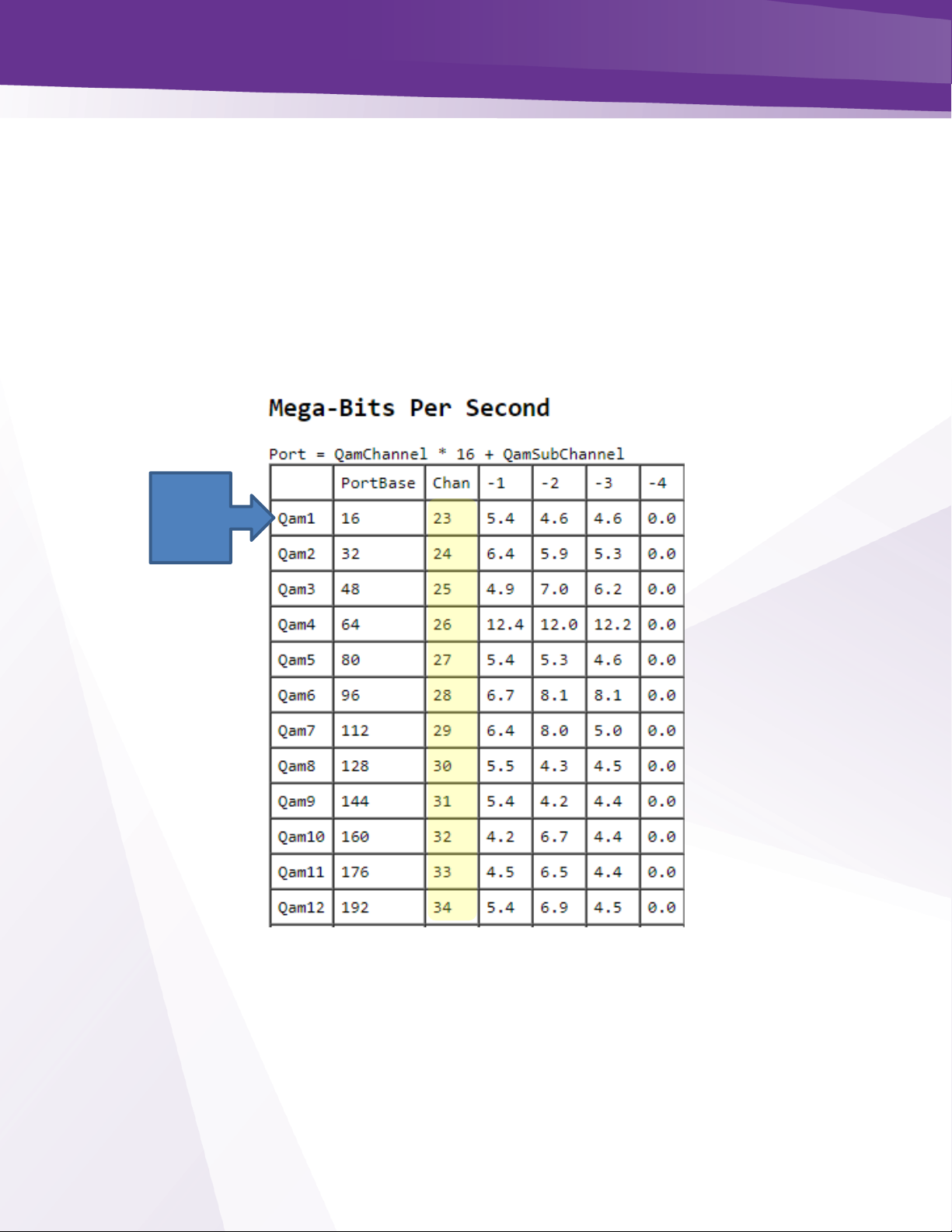
w w w . t e c h n i c o l o r . c o m / m c s
Page 90
The three boxes at the bottom of the control screen are used to reference the following:
➢ Index= Sets the QAM index referenced in the first column of the QAM table. By default the field
is populated with -1. As a security measure you must delete the -1 and enter the QAM Index.
➢ Freq = Sets the channel to be assigned to the QAM referenced in the first box
➢ Count= Sets the QAMs to be set in sequential order
In the example below shown in Figure 71, we are setting QAM 1 to channel 23 and will set all
the QAM outputs in sequential order. When submitted the QAM output channels will be listed in
the column labeled Chan in the QAM table as shown below in Figure 71 and Figure 72.
Figure 71 QAM Table
QAM
Index
Page 91

w w w . t e c h n i c o l o r . c o m / m c s
Page 91
Figure 72 -QAM Table
Page 92
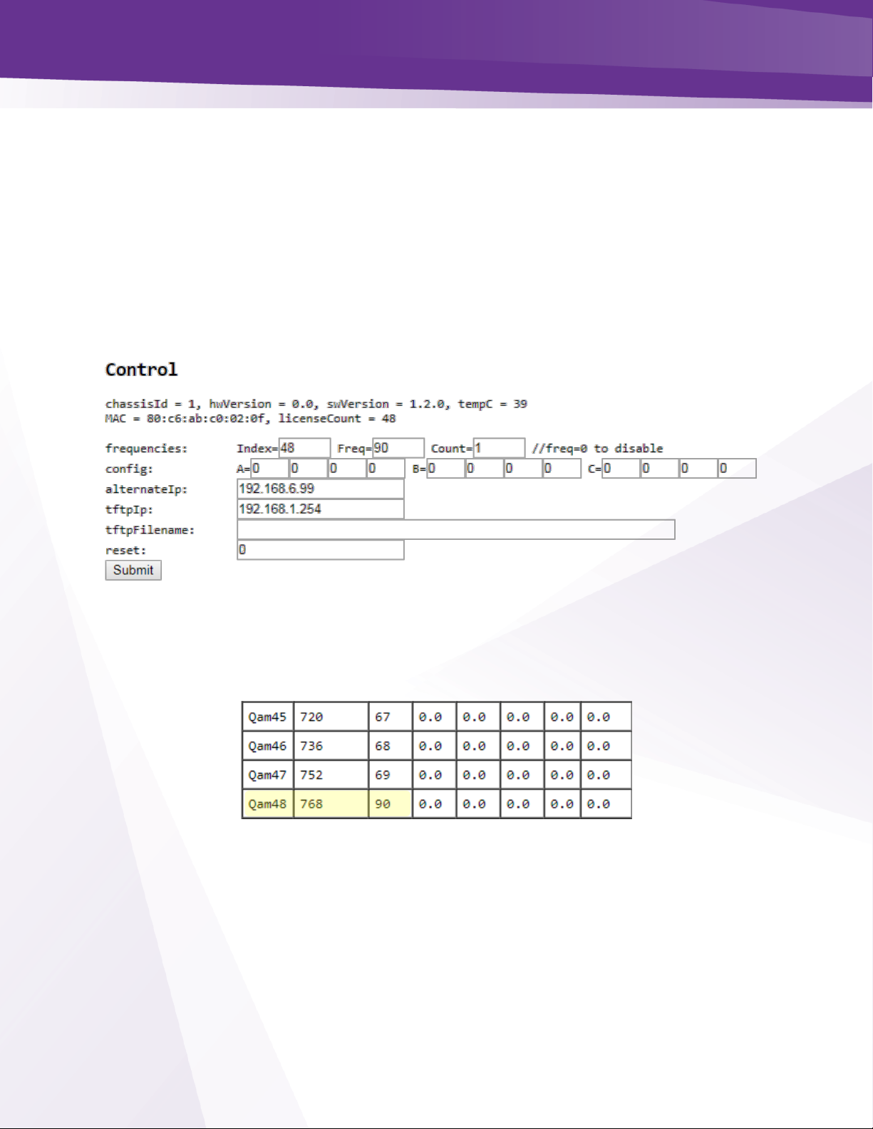
w w w . t e c h n i c o l o r . c o m / m c s
Page 92
34.4 Setting Unique RF output to a QAM
RF channel outputs can be assigned to an individual QAM or group of QAMS
To set a unique RF output to an induvial QAM:
➢ Enter the QAM number in the Index box
➢ The desired output channel in the Freq box
➢ Enter a 1 in the Count box to change only that QAM output
In the example shown below in Figure 73 we will change QAM Index 48 to channel 90.
Figure 73 - Changing a Single QAM Output
Once you enter the information click submit. You will see QAM index 48 now has an output
channel of 90 as shown below in Figure 74.
Figure 74 - Individual QAM Output Change
Page 93
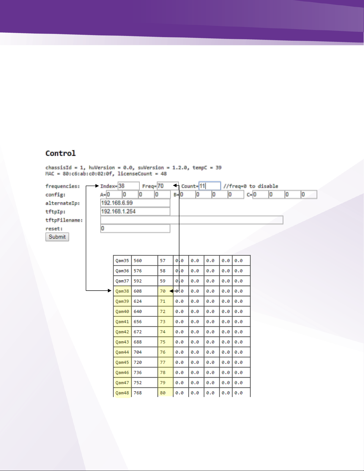
w w w . t e c h n i c o l o r . c o m / m c s
Page 93
34.5 Setting Unique outputs to a group of QAMs
A group of QAMs can be set to a unique group of output channels:
➢ Enter the first QAM to be set in the Index box
➢ Enter the channel number in the Freq box
➢ Enter the number of QAMS to be set in sequential order
In the example shown in Figure 75 and Figure 76 we will change the outputs of QAM 38-48 to
channels 70-80.
Click Submit and the new QAM outputs will display table.
Figure 75 - Changing Outputs Channels on a Group of QAMS
.
Figure 76 - QAM Group Outputs
Page 94

w w w . t e c h n i c o l o r . c o m / m c s
Page 94
35 Troubleshooting
35.1 Software Version
Before troubleshooting be sure all components of the COM3000 are running current software.
Software can be found on the Technicolor website or from your distributor.
35.2 Verify RF
Before troubleshooting the COM3000 verify satellite signal passes EIV check on the DIRECTV
AIM meter at the COM51 input.
Use a test TV and field strength meter to test picture quality directly from the COM3000 QAM
output.
➢ Signal from the QAM will need to be attenuated to correct levels
➢ A DCI401MCS set back box is a good troubleshooting tool to verify picture quality.
35.3 COM51 Reset Button
Figure 77 below shows the COM51 reset button, accessed via a small hole in the front of the
card below the AT&T logo.
The button serves three purposes:
➢ Momentarily depressing the button results in a COM51 reset, like a power cycle or a software
reset
➢ Depressing the reset button for 30 seconds will result in a factor reset
o All settings will revert to factory
o IP address will revert to default for chassis / slot
o License files will revert to HD Streamout
➢ Holding the reset button for 60 seconds will result in a factory reset and force a recovery to
download an image from an external TFTP server. Server must run on a PC with an IP of
192.168.1.254.
➢ File should be the latest COM51 software with the filename changed to “COM51.bin”
RESET
Page 95

w w w . t e c h n i c o l o r . c o m / m c s
Page 95
Figure 77 - COM51 Reset
35.4 Troubleshooting Common Problems
The most common problems encountered with the COM3000 systems are due to poor RF signal
conditions or to bad or loose connections.
Before moving on to detailed troubleshooting of any problem, you should check the following:
➢ All necessary connections (Power, Ethernet, and coaxial cables) are fully plugged or screwed in.
➢ Proper RF signal levels are available at the inputs to the system.
➢ A AT&T / DIRECTV AIM meter must be used to test signal quality. An EIV test must return a fully
passing result on all transponders.
➢ COM51 RF input 1 is the lower RF input, connection of a DSWIM to this input will facilitate use
of the first 16 tuners.
o A DSiM connection to input two is required for a COM51 with 17 or more active tuners.
➢ Once you have ensured that all RF parameters are correct, try retuning and/or rebooting any
problematic cards.
If the problem persists, look over the following tips and review the appendices before contacting
your distributor.
35.5 Features and Licensing
The COM51 must be licensed to stream signal. In systems with a QAM20 or NTSC-8 this
license will be provided via the hardware when connected to the COM400 chassis.
If you are using a COM51 system in an IPTV system with no QAM or NTSC-8 the cards will
need to be licensed for use by your distributor.
➢ Symptoms of no IP license:
o All tuners will work after re-boot, after several minutes all tuner >1 will stop. COM51
card will display tuner >1 in red.
o Syslog will report, “No QAM found need license”.
Loading a COM51 license file overwrites any existing license in the card. Any new license file
must contain any existing licenses.
Tuner licenses are a separate file and will not affect or be affected by feature license files.
Technicolor support cannot load feature or tuner licenses on your equipment. You must contact
your distributor.
Page 96

w w w . t e c h n i c o l o r . c o m / m c s
Page 96
36 Preventing Pro:Idiom Key Loss
There are two mechanisms which may cause Pro:Idiom key loss in some commercial television
sets.
Unapproved mapping or remapping of PIDs
➢ If external video sources are using a PID location common the Pro:Idiom PID in DIRECTV
channels the TV may loose its ability to decrypt Pro:Idiom channels.
➢ High quality Edge QAM modulator with relocate the Pro:Idiom key PID to a protected range
➢ Separate off air and external video sources from Pro:Idiom channels.
37 Simultaneous QAM and Multicast IP Output
(Currently under development and testing as of May 2018)
The COM3000 system is capable of outputting both IP and QAM signals simultaneously. There
are certain limitations to sending programming from a COM51 to a multicast address and the
QAM20 simultaneously.
In order to accomplish both IP streaming and RF QAM output there are two options. In both
cases you must use an IP and port configuration compatible with the QAM20 alternate IP.
Use a different IP address for each program and a common port assignment. This option is
recommended as some TVs require port numbers >5000.
Example:
QAM will need an alternate IP of 239.X.0.0 and will route the stream to an output channel via
the last octet of the IP address. The last octet must match the port assignments on the QAM20.
239.0.0.17:5001 = QAM 1 port 17
239.0.0.18:5001 = QAM 1 port 18
239.0.0.19:5001 = QAM 1 port 19
239.1.0.17:5001 = QAM 2 port 17 (Second QAM would need alternate IP of 239.1.0.0)
In this scenario each card streams to the same IP with a different port assignment for each
channel
Example:
Multicast address 239.0.0.10:17. Enter an alternate address 239.0.0.10 in the QAM20. QAM
will look for streams by port number on the 239.0.0.10 network.
If the above example is used you would send programming to your IP network on 239.0.0.10:17
and to the QAM20 to output RF ch 23-1.
239.0.0.10:17 = ch 23-1
239.0.0.10:18 = ch 23-2
239.0.0.10:19 = ch 23-3
Page 97

w w w . t e c h n i c o l o r . c o m / m c s
Page 97
The port assignments on the QAM20 are static and cannot be changed. The QAM RF output
channels are agile.
If your customer has an existing IP scheme that is not compatible with these settings your
options would be to change the network configuration, including the TV rings, or to install
separate COM3000 systems for IP and RF.
Page 98

w w w . t e c h n i c o l o r . c o m / m c s
Page 98
38 Syslog Server Setup
The COM51 card syslog retains 500 lines of text for review in troubleshooting. Old entries are
deleted as new entries are added. To preserve syslogs for a longer period for troubleshooting a
syslog server may be set up on a local PC.
There are multiple syslog programs available. For this exercise we are using TFTPD32.
Tftpd32 is a free program you can download at http://tftpd32.jounin.net/tftpd32_download.html.
You may have used this program in the past to upgrade software on COM24 cards.
Below are the steps to create a syslog server:
Download and install Tftpd32
Enter IP address of your PC in the COM51 card. (PC network card must be set to the same
subnet as the COM51 system. In this example we are using the default 192.168.3.XXX network
settings.
Below is the result of an IPCONFIG command line request showing the network settings:
PC IP ADDRESS
Page 99

w w w . t e c h n i c o l o r . c o m / m c s
Page 99
From the Advanced Edit page scroll to the User Config section:
Enter the IP address of your PC in the “LOG_IP” field. Leave the “Log_Level” field blank.
Repeat this step for each card you want to capture logs from.
Reboot the card(s)
Create a directory named “syslog” in the root of the C drive. (c:\syslog)
Open the Tftpd32 program and click on the GLOBAL settings. Select Syslog Server, uncheck
other boxes. Click OK.
Enter PC IP address
Page 100

w w w . t e c h n i c o l o r . c o m / m c s
Page 100
In the TFTP settings menu go to SYSLOG check the “Save syslog messages” box and enter the
file location in the “To file” field: Click OK
From the TFTP main screen select the “Syslog Server” tab. You will see the syslog information
displayed in the text box, designated by the IP address of the card in the “from” column.
Open the syslog.txt file you created and verify the log information is populating the file.
The syslog files will grow large pretty quickly especially if you are logging several COM51
cards simultaneously. You may want to archive the files every couple of hours.
To archive the files:
Stop the Tftpd program
Change the name of the syslog.txt file to something you can refer to later such as
1025_1600syslog.txt. In this case I used the date and time.
Restart the Tftpd server and verify the new syslog file is populating.
File Location
Click Box
 Loading...