

Page 1
TECHNICOLOR COM1000/COM2000
System Training Workshop
COM1000/COM2000 System Troubleshooting
Strictly Confidential
Page 2

Welcome
Welcome to the Technicolor COM1000/2000 System
Troubleshooting workshop
Your instructor is Mark Anderson
The Technicolor MCS Management Team is:
• Rob Rhodes – Director of R&D
• Doug Strachota – Product Manager
• Tony Watters – Sales Manager
Page 3

Classroom Etiquette
Please DO
• Turn all cellphones to vibrate or off
• Keep all conversations relevant to the current topic
• Feel free to ask questions when needed
Please DO NOT
• Talk on your cell phone
• Carry on side conversations
• Be afraid to ask questions
• Be disruptive to others in the class
Page 4

Troubleshooting
Defined
The identification and resolution of problems, especially problems
of a technical nature
The process of solving problems, especially complicated problems
in a system
Philosophy
To get to the root cause of a given system failure in the least
number of steps possible by partitioning the system into
manageable sections, using the symptoms to pick a starting point
and following the signal through the various sections until the
offender is identified
Page 5
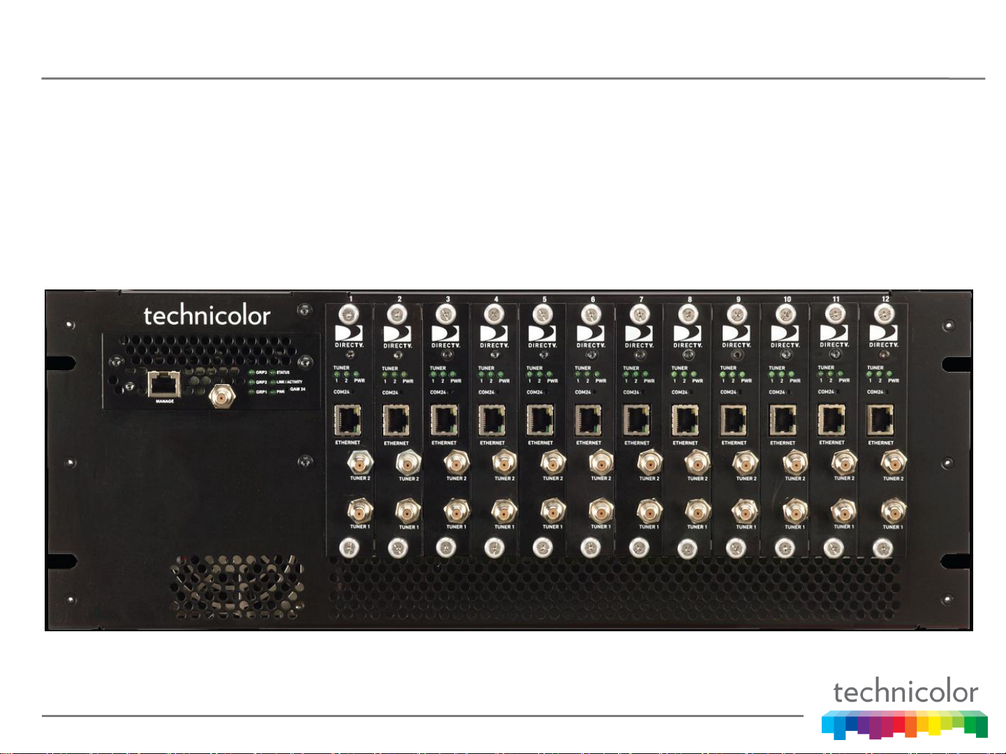
THE COM1000 HEAD END
Front view of a COM200 chassis with 12 COM24 cards and a
QAM6 installed
Page 6
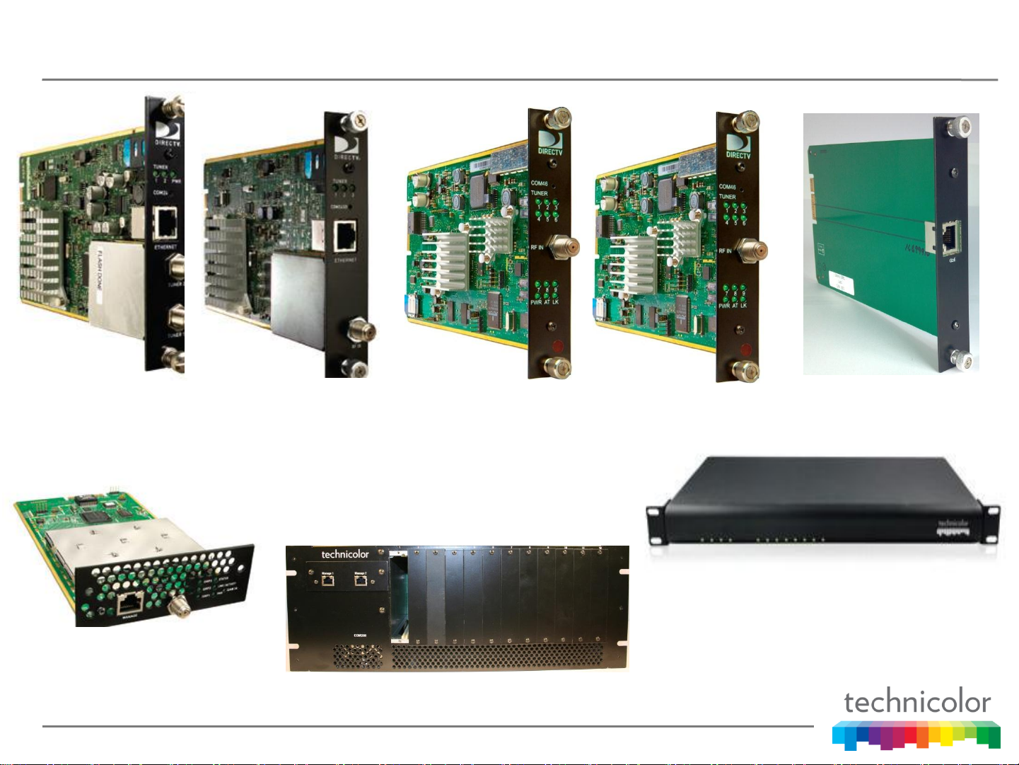
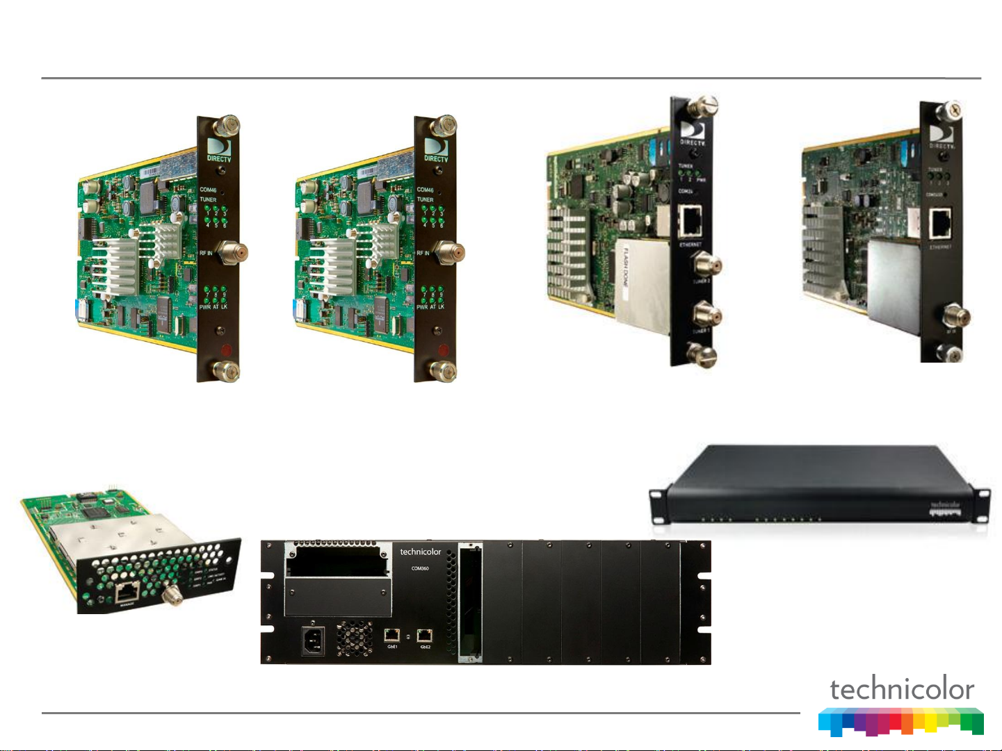
COM1000 HEAD END COMPONENTS
COM24 COM24-FLX
QAM6
COM200
COM46-FLX COM46
ATSC-8
GbE1
Page 7

A COM1000 HEAD END MAY INCLUDE
• COM24 cards
• COM24-FLX cards
• COM46 cards
• COM46-FLX cards
• QAM6/24 card
• GbE-1 card
• COM100/200 chassis
• Off air receivers i.e. ATSC-8
• EAS system
• Local content streamers i.e. PC
• Ethernet switch
Page 8
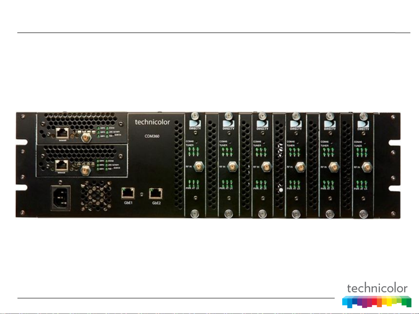
The COM2000 Head End
Front view of a COM360 with six COM46 Cards and QAMS
Page 9
COM2000 HEAD END COMPONENTS
COM46
QAM6
COM46-FLX
COM360
COM24 COM24-FLX
ATSC-8
Page 10

A COM2000 HEAD END MAY INCLUDE
• COM46 cards
• COM46-FLX cards
• COM24 cards
• COM24-FLX cards
• QAM6 cards
• COM360 chassis
• Off air receivers i.e. ATSC-8
• EAS system
• Local content streamers i.e. PC
• Ethernet switch
Page 11

THE COM1000/COM2000 INSTALLATION
For troubleshooting purposes the COM1000/COM2000 installation
can be split into three main sections.
o The RF Plant
o The Head End
o The Distribution Network
Our first goal in troubleshooting the system is to determine which
of these three areas the problem most likely resides in.
Page 12
THE RF PLANT
All COM1000/COM2000 RF plants should be designed and installed
following the practices outlined in the latest version of this DIRECTV
document or the current replacement wherever possible.
Page 13

THE RF PLANT
The COM46 card has 9 tuners and is SWM ONLY, NO multiswitch RF
plants can be used with the COM46 card
This means that every COM46 card requires a complete SWiM 8 tap
exclusively
When adding COM46 cards in existing COM1000 systems with
COM24 and/or COM24-FLX cards the rules and guidelines in the
DIRECTV COM24/SWiM Use Cases and Installation Constraints
document and the Technicolor COM24 and COM24-FLX Application
Note 03132013 documents should be followed at all times
Page 14

RF PLANT COMPONENTS
The RF plant may include some or all of the following
components:
• The Dish/LNB and mount
• Polarity locker/LNB power supply
• Leveling amplifier
• SWM module and power supply
• Multi-switch panel and power supply
• B Band converters
• RF Splitters
• Various cabling and connectors
Page 15

P.S. – YOUR PROBLEM IS RF
In 2010 - 2012 the number
one system issue in the
field investigated by
Technicolor were RF plant
related failures
A solid RF plant is critical
to your success. It all starts
with a good clean solid
signal from the satellites
Page 16

CHECK THE SYSLOG
Mar 11 06:57:04 com24-10-5 syslog: HDXEA: 1
Mar 11 06:57:06 com24-10-5 syslog: HDXEA: 0
Mar 11 06:57:14 com24-10-5 syslog: a: MOcount(1,4421624)
Mar 11 06:57:17 com24-10-5 syslog: a: Status: RID=033081961030 CAM_ID=002299005104 Chassis=10
Slot=5 Temp=32,43 Fans=1,1 Power=2,1 Uptime=1187823 Auth=1 Paired=1 Tuners=6580964,9,-36;
3900930,3,-34; 0,14,-51
Mar 11 06:57:49 com24-10-5 syslog: a: MOcount(0,7897772)
Mar 11 06:58:03 com24-10-5 syslog: HDXEA: 1
Mar 11 06:58:03 com24-10-5 syslog: HDXEA: 0
A typical syslog for a properly functioning COM24 card with a good
RF plant. Notice it contains only encryption key, marker object count
and system status messages.
Page 17

CHECK THE SYSLOG
Mar 11 07:06:50 com24-10-5 syslog: a: MOcount(0,7901373)
Mar 11 07:07:03 com24-10-5 syslog: a: FilterPause(2, 2)
Mar 11 07:07:03 com24-10-5 syslog: a: Tuner(index=0, quality=0, strength=0, errors=0, event=32)
Mar 11 07:07:03 com24-10-5 syslog: a: Tuner(index=1, quality=0, strength=0, errors=0, event=32)
Mar 11 07:07:03 com24-10-5 syslog: a: FilterPause(2, 4)
Mar 11 07:07:03 com24-10-5 syslog: a: Tuner(index=2, quality=0, strength=0, errors=0, event=32)
Mar 11 07:07:03 com24-10-5 syslog: a: FilterPause(10, 14)
Mar 11 07:07:03 com24-10-5 syslog: a: FilterPaused
Mar 11 07:07:03 com24-10-5 syslog: a: CC errors index=0 CCtotal=32
Mar 11 07:07:03 com24-10-5 syslog: a: CC errors index=1 CCtotal=756
Mar 11 07:07:04 com24-10-5 syslog: a: No packets(0, 1)
Mar 11 07:07:04 com24-10-5 syslog: a: No packets(1, 1)
A syslog for a malfunctioning COM24 card with RF plant issues.
Notice it contains messages indicative of signal issues.
Page 18

CHECK THE SYSLOG
Mar 11 07:22:04 buildroot user.notice syslog: a: MOcount(9228,9225,461,9220,9216,9212,9211,9208)
Mar 11 07:22:04 buildroot user.crit syslog: NDS.CDI HDXEA completed: 6
Mar 11 07:22:04 buildroot user.crit syslog: NDS.CDI HDXEA completed: 3
Mar 11 07:22:04 buildroot user.crit syslog: NDS.CDI DESC HDX_SetDescrambler:
DEMUX_DESCRAMBLER_SET_CONTROL_WORD, fd=102, index=13, x_con=6, stream_pid=4144,rv=0
Mar 11 07:22:04 buildroot user.crit syslog: NDS.CDI DESC HDX_SetDescrambler:
DEMUX_DESCRAMBLER_SET_CONTROL_WORD, fd=101, index=12, x_con=6, stream_pid=4146,rv=0
Mar 11 07:22:24 buildroot user.notice syslog: a: Status: RID=036624337402 CAM_ID=003805104894
Chassis=6 Slot=3 Temp=52 Fans=1,1 Uptime=664579 Auth=1 Paired=1 Tuners=3900943,8,-24;
3900971,14,-23; 3365432,15,-25; 5601806,8,-27; 3900936,10,-23; 4728190,10,-19; 3900952,11,-20
Mar 11 07:22:42 buildroot user.crit syslog: NDS.CDI HDXEA completed: 2
A typical syslog for a properly functioning COM46 card with a good
RF plant. Notice it contains only encryption key, marker object count
and system status messages.
Page 19

CHECK THE SYSLOG
Mar 11 06:57:07 buildroot user.notice syslog: a: CC errors index=0 CCtotal=12
Mar 11 06:57:07 buildroot user.notice syslog: a: CC errors index=1 CCtotal=2
Mar 11 06:57:07 buildroot user.notice syslog: a: CC errors index=2 CCtotal=151
Mar 11 06:57:07 buildroot user.notice syslog: a: CC errors index=6 CCtotal=7
Mar 11 06:57:07 buildroot user.notice syslog: a: CC errors index=7 CCtotal=55
Mar 11 06:57:08 buildroot user.err syslog: a: >>> Tuner(0) Lost Lock <<<
Mar 11 06:57:08 buildroot user.err syslog: a: >>> Tuner(2) Lost Lock <<<
Mar 11 06:57:08 buildroot user.err syslog: a: >>> Tuner(8) Lost Lock <<<
Mar 11 06:57:08 buildroot user.notice syslog: a: No packets(0, 1)
Mar 11 06:57:08 buildroot user.notice syslog: a: No packets(1, 1)
Mar 11 06:57:08 buildroot user.notice syslog: a: No packets(6, 1)
Mar 11 06:57:08 buildroot user.notice syslog: a: No packets(7, 1)
A syslog for a malfunctioning COM46 card with RF plant issues.
Notice it contains messages indicative of signal issues.
Page 20

TOOLS FOR TROUBLESHOOTING
The DIRECTV Advanced Installation Meter
This device should be used for all aspects of the
installation, verification and troubleshooting of the RF
plant
Page 21

VERIFICATION OF THE RF PLANT
SWM or Multi-Switch RF
Conditioning and
Distribution
When testing the RF plant connect the AIM to F connector on
the cable feeding the COM24 card.
Page 22

VERIFICATION OF THE RF PLANT
SWM RF Conditioning
and Distribution
When testing the RF plant connect the AIM to F connector on
the cable feeding the COM46 card.
Page 23

VERIFYING THE RF PLANT WITH THE AIM
Run the EIV Plus Test at the IRD to verify the signal to the
COM46/COM24 card(s)
If there are ANY failures during this test consult the DIRECTV
Appendix A - MDU/Commercial Advantage Validation and
Troubleshooting Procedure to identify and correct the failure.
Page 24

TOOLS FOR TROUBLESHOOTING
A DCI401MCS and a small television monitor with RF and HDMI
inputs make an ideal troubleshooting tool for an RF based
distribution network
Page 25

VERIFICATION OF QAM OUTPUT
COM200 Chassis
The output of the QAM is checked at the F connector on the
front of the QAM module
Page 26

VERIFICATION OF QAM OUTPUT
COM360 Chassis
The output of the QAM is checked at the F connector on the
front of the QAM module(s)
Page 27

TOOLS FOR TROUBLESHOOTING
Important information about the strength and quality of the signal can be
obtained by using the DCI401MCS menu and selecting Settings/System Info.
Page 28

TOOLS FOR TROUBLESHOOTING
The VLC media player is an excellent tool for verification of an IP
stream coming from a COM1000 system
Page 29

VERIFICATION OF IP OUTPUT
The IP output of a COM24 or COM24-FLX can be checked using
the front Ethernet port. This requires you to connect the port and
reset the card to make the front port active
Page 30

VERIFICATION OF IP OUTPUT
The IP output of the chassis is verified at the Gigabit Ethernet
connector located on the rear of the COM200 chassis
Page 31

VERIFICATION OF IP OUTPUT
The IP output of the chassis is verified on the Gigabit Ethernet
connectors located on the front of the COM360 chassis
Page 32

VERIFICATION OF IP OUTPUT
Multicasting a Video Stream
The IPv4 multicast address range includes the addresses from
224.0.0.0 to 239.255.255.255
To IP multicast a channel on the simple tune page set the following:
Dest_IP_Address = 225.0.0.1
Dest_Port_Number = 123
Major_Number = 100
To play a multicast stream with VLC select the Media pull down
then select Open Network Stream and enter UDP://@225.0.0.1:123
Page 33

VERIFICATION OF IP OUTPUT
Unicasting a Video Stream
The IPv4 private address ranges include:
10.0.0.0 to 10.255.255.255
172.16.0.0 to 172.31.255.255
192.168.0.0 to 192.168.255.255
To IP unicast a channel on the simple tune page set the following:
Dest_IP_Address = 10.0.0.1
Dest_Port_Number = 123
Major_Number = 100
To play a unicast stream with VLC select the Media pull down then
select Open Network Stream and enter UDP://@10.0.0.1:123
Page 34

THE SIGNAL DISTRIBUTION NETWORK
The distribution network type could be:
• RF based (coax wiring)
• Z-Band (RF over cat5e or cat6 twisted pair)
• IP based (cat5e or equivalent wiring)
Page 35

THE SIGNAL DISTRIBUTION NETWORK
The components of the distribution network may
include:
• Ethernet switches, routers, etc
• Combiners
• RF amplifiers
• Splitters
• Various cabling and connectors
• Pro:Idiom decryption device and/or set back boxes i.e
DCI401MCS, Enseo, etc.
• Television sets
Page 36

TELEVISIONS – THE GREY AREA
There are known issues with televisions that prevent them from
working properly with the COM1000/COM2000 and the DIRECTV
signal. Some of these issues are:
• No support for H.264 encoding at all
• No support for MPEG2 encoding at all
• No support for MPEG1 Layer II audio encoding
• No support for Pro:Idiom encryption
• Lip Sync issues
Page 37

OTHER INSTALLATION CONSIDERATIONS
• Incoming AC power
• System grounding
• Equipment room environment (temperature,
humidity, dust, etc.)
Page 38

COM1000/COM2000 System Toolkit
Your COM1000/COM2000 troubleshooting toolkit should contain
most if not all of the following:
• COM24mdns.exe
• Web browser - IE, Chrome, Firefox, Safari
• TFTP server - tftpd32
• DHCP server - tftpd32
• Syslog server - tfpd32, Kiwi Syslog Daemon
• IP video playback utility, VLC
• Packet Capture - Wireshark
• DCI401MCS
• Video monitor with HDMI input
• AIM
Page 39

IS THIS A TECHNICOLOR PROBLEM?
For a COM1000/COM2000 system Technicolor is responsible for
the signal from the input F connector on the receiver cards
(COM24, COM24-FLX, COM46, COM46-FLX) to the output F
connector on the QAM(s) if present or the Gigabit Ethernet
connector(s) if there is no QAM in the system.
In the case of the DCI401MCS Technicolor is responsible for the
signal from the input F connector to the output F and HDMI
connectors.
For the ATSC-8 Technicolor is responsible for the signal from the
input F connectors to the Ethernet output connectors.
Page 40

WHAT IS NOT A TECHNICOLOR PROBLEM?
• Any part of the RF plant from the dish to the COM1000/COM2000
system
• Any part of the management network including any PC, switch,
router, etc.
• Any part of the RF distribution network from the
COM1000/COM2000 system
• Any part of the network in an IP distribution from the
COM1000/COM2000 system
• Any part of the network in a Z band distribution from the
COM1000/COM2000 system
• Televisions and television related issues
Page 41

The Path for Escalating Problem Resolution
It is requested that all calls to Technicolor
for support with the COM1000/COM2000
systems originate from the distributors.
Technicolor will interface directly with
dealers or end customers as required but
prefers distributor involvement whenever
possible.
Page 42

Contacting Technicolor MCS
The Technicolor MCS website:
http://www.technicolor.com/en/solutions-services/connected-home/commercial-video-solutions
The Technicolor MCS toll free support number:
1-855-297-5820
The Technicolor MCS email address:
mcssales@technicolor.com
Email to: Mark.Anderson2@technicolor.com
Telephone 317-587-5081
Page 43

Before Escalating Problems to Technicolor
In order for Technicolor to understand and help you resolve
customer field issues in a timely manner, we must have good
information to understand the system configuration and the
problem being described. Prior to contacting Technicolor you
should be sure that the system is running the latest QAM and COM
software versions (you will be asked).
This information MUST come from the field. Technicolor generally
has no working knowledge of any particular configuration or system
location.
Page 44
Thank You
 Loading...