

Page 1

CGA4131 BUSINESS GATEWAY
OPERATIONS GUIDE
Version – 0.2
Copyright © 2018
Technicolor
Systems All Rights Reserved
No portions of this material may be reproduced in any form without the written
permission of Technicolor.
Page 2

3/6/2018 Proprietary and Confidential - Technicolor ii
Revision History
Revision
Date
Description
0.1
3/2/2018
Initial draft
0.2
3/6/2018
Updated the baseline configuration file; added details for
spectrum analyzer and MTA based on review
comments.
Page 3

3/6/2018 Proprietary and Confidential - Technicolor iii
Table of Contents
1! Introduction ............................................................................................................................ 1!
1.1! Technicolor CGA4131 Business Gateway ...................................................................... 1!
2! WebUI Access Overview ..................................................................................................... 10!
3! Initial Configuration and Setup ............................................................................................ 12!
3.1! Accessing the Web UI ................................................................................................... 12!
4! Web UI Guide ...................................................................................................................... 13!
5! Status Pages ....................................................................................................................... 15!
5.1! Overview ....................................................................................................................... 15!
5.2! Gateway ........................................................................................................................ 16!
5.3! Local Network ............................................................................................................... 17!
5.4! Wireless ........................................................................................................................ 19!
5.5! DOCSIS Status ............................................................................................................. 21!
5.6! DOCSIS Signal ............................................................................................................. 24!
5.7! DOCSIS Log ................................................................................................................. 27!
5.8! Spectrum Analyzer ........................................................................................................ 27!
5.8.1! SNMP provisioning for Spectrum Analyzer ............................................................ 29!
5.9! System .......................................................................................................................... 29!
6! Connection .......................................................................................................................... 33!
6.1! Devices ......................................................................................................................... 33!
6.2! LAN ............................................................................................................................... 33!
6.2.1! SNMP provisioning for LAN ................................................................................... 35!
6.3! WAN .............................................................................................................................. 36!
6.3.1! User provisioning for WAN..................................................................................... 36!
6.3.2! SNMP provisioning for WAN .................................................................................. 40!
6.3.3! Dual Stack Router .................................................................................................. 41!
6.3.4! eSAFE .................................................................................................................... 41!
6.4! Routing .......................................................................................................................... 42!
6.4.1! Enable / Disable IGMP Proxy ................................................................................ 42!
6.4.2! RIP ......................................................................................................................... 43!
6.4.3! User provisioning for RIP ....................................................................................... 44!
6.4.4! SNMP provisioning for Advanced Routing Feature ............................................... 45!
Page 4

3/6/2018 Proprietary and Confidential - Technicolor iv
6.5! Modem .......................................................................................................................... 45!
6.6! MTA ............................................................................................................................... 45!
6.7! Network Time ................................................................................................................ 47!
7! Wireless ............................................................................................................................... 49!
7.1! Radio ............................................................................................................................. 49!
7.1.1! User provisioning for Radio ................................................................................... 51!
7.1.2! SNMP provisioning for Radio ................................................................................. 52!
7.1.3! Procedure to set SNMP Wireless Settings ............................................................ 54!
7.2! Wireless Security .......................................................................................................... 54!
7.2.1! User provisioning for Security ................................................................................ 55!
7.2.2! SNMP provisioning for Security ............................................................................. 56!
7.3! Advanced Wireless Settings ......................................................................................... 56!
7.3.1! User provisioning for Advanced Wireless settings ................................................. 58!
7.3.2! SNMP provisioning for Advanced Wireless Setting ............................................... 60!
7.4! Guest Network .............................................................................................................. 61!
7.4.1! User provisioning for Guest Network ..................................................................... 63!
7.4.2! SNMP provisioning for Guest Network .................................................................. 65!
7.5! MAC Control .................................................................................................................. 68!
7.5.1! User provisioning for MAC Control ........................................................................ 69!
7.5.2! SNMP provisioning for MAC Control ..................................................................... 69!
7.6! WPS .............................................................................................................................. 70!
7.6.1! User provisioning for WPS ..................................................................................... 71!
7.7! QoS ............................................................................................................................... 72!
7.7.1! User provisioning for QOS ..................................................................................... 73!
7.7.2! SNMP provisioning for QoS ................................................................................... 74!
7.8! Hotspot .......................................................................................................................... 74!
7.8.1! Enabling GRE hotspot with cable modem configuration file .................................. 76!
7.8.2! SNMP provisioning for Hotspot .............................................................................. 77!
8! Security ................................................................................................................................ 78!
8.1! Firewall .......................................................................................................................... 78!
8.1.1! User provisioning for Firewall ................................................................................ 81!
8.1.2! SNMP provisioning for Firewall .............................................................................. 82!
8.2! IP Filter .......................................................................................................................... 83!
Page 5

3/6/2018 Proprietary and Confidential - Technicolor v
8.2.1! User provisioning for IP Filter ................................................................................ 83!
8.3! Device Filter .................................................................................................................. 83!
8.3.1! User provisioning of Device Filter .......................................................................... 84!
8.3.2! SNMP provisioning for Device Filter ...................................................................... 85!
8.4! Access Control .............................................................................................................. 85!
8.4.1! User provisioning for Access Control ..................................................................... 86!
8.4.2! SNMP provisioning for Access Control .................................................................. 87!
8.5! Service Filter ................................................................................................................. 87!
8.5.1! User provisioning for Service Filter ........................................................................ 88!
8.5.2! SNMP provisioning for Service Filter ..................................................................... 88!
8.6! VPN Tunnel Settings ..................................................................................................... 89!
8.6.1! User provisioning for VPN ..................................................................................... 91!
8.7! Email settings ................................................................................................................ 93!
8.7.1! User provisioning for Email .................................................................................... 94!
8.7.2! SNMP provisioning for Email ................................................................................. 94!
8.8! Report ........................................................................................................................... 95!
9! Applications ......................................................................................................................... 97!
9.1! Port Forward ................................................................................................................. 97!
9.1.1! User provisioning for Port Forward ........................................................................ 97!
9.2! Port Trigger ................................................................................................................... 98!
9.2.1! User provisioning for Port Triggering ..................................................................... 98!
9.2.2! SNMP provisioning for Port Forwarding and Port Triggering ................................. 99!
9.3! Port Filter ....................................................................................................................... 99!
9.3.1! User provisioning for Port Filter ........................................................................... 100!
9.4! DDNS .......................................................................................................................... 100!
9.4.1! User provisioning for DDNS ................................................................................. 101!
9.5! DMZ ............................................................................................................................ 101!
9.5.1! SNMP provisioning for DMZ ................................................................................ 102!
9.6! UPnP ........................................................................................................................... 103!
9.6.1! User provisioning of UPnP ................................................................................... 103!
9.6.2! SNMP provisioning for UPnP ............................................................................... 104!
9.7! IP Passthrough ........................................................................................................... 105!
9.8! SIP ALG ...................................................................................................................... 106!
Page 6

3/6/2018 Proprietary and Confidential - Technicolor vi
10! Administration .................................................................................................................... 108!
10.1! User ......................................................................................................................... 108!
10.2! Remote Management .............................................................................................. 108!
10.2.1! SNMP provisioning for Remote Management ..................................................... 110!
10.2.2! Telnet / SSH access ............................................................................................ 110!
10.3! Backup & Restore ................................................................................................... 111!
10.3.1! User provisioning for Backup & Restore .............................................................. 111!
10.4! Reboot & Reset ....................................................................................................... 112!
10.4.1! Factory Reset ....................................................................................................... 112!
10.4.2! SNMP provisioning for Reset & Reboot ............................................................... 113!
10.4.3! Reset Username & Password .............................................................................. 113!
10.5! Troubleshooting ....................................................................................................... 113!
10.6! Remote Log ............................................................................................................. 114!
11! Diagnostics ........................................................................................................................ 116!
11.1! System ..................................................................................................................... 116!
11.2! Interface .................................................................................................................. 117!
11.3! Network ................................................................................................................... 122!
11.4! Wireless ................................................................................................................... 123!
11.5! Clients ...................................................................................................................... 126!
11.6! Internet .................................................................................................................... 127!
12! Mixed mode ....................................................................................................................... 128!
12.1! Procedure to configure Mixed mode ....................................................................... 128!
12.2! SNMP provisioning for Mixed mode ........................................................................ 128!
13! Isolation ............................................................................................................................. 129!
13.1! SNMP provisioning for APIsolation ......................................................................... 129!
14! TR-069 ............................................................................................................................... 131!
14.1! User provisioning forTR-069 ................................................................................... 131!
14.2! SNMP provisioning for TR-069 ................................................................................ 132!
15! TR-143 ............................................................................................................................... 133!
16! Appendix 1: Sample CM Config file ................................................................................... 134!
17! Appendix 2: Sample bitmask configuration for Web UI ..................................................... 140!
18! Abbreviations and Acronyms ............................................................................................. 144!
Page 7

1 Introduction
This document provides information on the Technicolor CGA4131 Business Gateway to
Technicolor’s service provider customers. The audience for this document includes those
personnel who are tasked with deploying, maintaining, and servicing this device as well as
those who provide answers to questions from end users.
1.1 Technicolor CGA4131 Business Gateway
The CGA4131 Business Gateway allows cable MSOs to respond to small and medium
businesses with a business-centric set of data, voice, and wireless features. The CGA4131
is a DOCSIS® 3.1 broadband gateway offering triple-play services: up to Gigabit speeds,
business VoIP and next generation 802.11ac Wi-Fi. The device can be configured using a
web page user interface accessible by the user or remotely by the MSO by SNMP/TR-069.
The Technicolor CGA4131 offers the following features:
• Compliance with DOCSIS 3.0 and 3.1 standards to deliver high-end performance
and reliability
• High performance Broadband Internet Connectivity
• Eight-line embedded digital voice adapter for wired telephony service
• Two 802.11 Wi-Fi radios for dual-band concurrent operation, with up to eight SSIDs
per radio
• Wi-Fi Protected Setup™ (WPS) support with hardware push button for simplified and
secure wireless setup
• User configurable Access Control and firewall settings
• Compact design allows for horizontal or wall-mounted operation
• Color coded interface ports and corresponding cables to simplify installation and
setup
• Front panel LEDs show operational status for the user
• Automatic software upgrade capability for the service provider
• TR-069 Compliant Remote Management Capabilities
Page 8
3/6/2018 Proprietary and Confidential - Technicolor 2
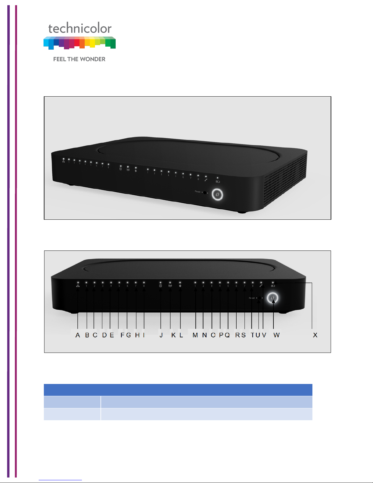
Front Panel View and LED Operations
The following images represent the front panel view of the CGA4131 TCH2-GA-TBR.
Figure 1.1
Figure 1.2
Ethernet LED (Item A)
State
Description
Solid on
Ethernet is enabled with AC power
Off
Ethernet is not enabled
Page 9
3/6/2018 Proprietary and Confidential - Technicolor 3
Ethernet Ports 1-8LEDs (Items B - I)
The CGA4131 has 8 Ethernet ports. The status of each port is shown by its LED state:
Port 1
LED B
Port 2
LED C
Port 3
LED D
Port 4
LED E
Port 5
LED F
Port 6
LED G
Port 7
LED H
Port 8
LED I
State
Description
Solid on
The port is connected.
Off
The port is not connected
Blinking
Data is being transferred
Internet LED (Item J)
State
Description
Solid on
Internet Service is active
Off
There is no Internet Service
Wi-Fi LED (Item K)
State
Description
Blinking
Data (2.4GHz or 5GHz) is active over the wireless connection
Off
Wi-Fi access point is not enabled
Online LED (Item L)
State
Description
Solid on
Connected to the service provider’s network. Even when internet is
not active, LED is on. Data traffic can be used.
Blinking
Trying to acquire Upstream, Downstream frequencies
Page 10

3/6/2018 Proprietary and Confidential - Technicolor 4
Telephone Lines 1-8 LEDs (Items M - T)
The CGA4131 has 8 telephone lines. The status of each telephone lines shown by its LED
state:
Telephone
Line 1
LED M
Telephone
Line 2
LED N
Telephone
Line 3
LED O
Telephone
Line4
LED P
Telephone
Line5
LED Q
Telephone
Line6
LED R
Telephone
Line7
LED S
Telephone
Line8
LED T
Reset Button (Item U)
Press the Reset button to reset the box.
Press the Reset button approximately 12-13 seconds to restore to factory settings.!
Telephone Line LED (Item V)
State
Description
Solid on
MTA Voice interface is operational
Off
MTA Voice interface is not operational
WPS (Item W)
Battery LED (Item X)
State
Description
Solid on
Telephone line is registered successfully with the call manager
Blinking
Telephone line has either gone off-hook or is in active call
Off
Telephone line is not registered with the call manager
State
Description
Blinking
WPS Process initialized and lasts for 2 minutes
Off
No WPS activity
State
Description
Off
Device is off, or AC power is on or Battery is not installed
Solid on
On Battery Power
Blinking
Battery needs replacement
Page 11
3/6/2018 Proprietary and Confidential - Technicolor 5
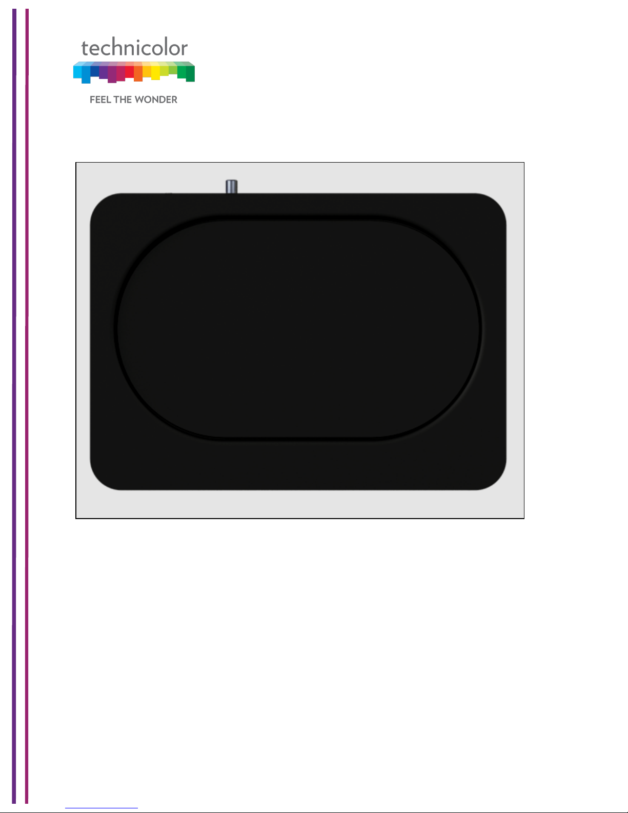
Top View
The following image depicts the top view of the CGA4131 TCH2-GA-TBR.
Figure 1.3
Page 12
3/6/2018 Proprietary and Confidential - Technicolor 6
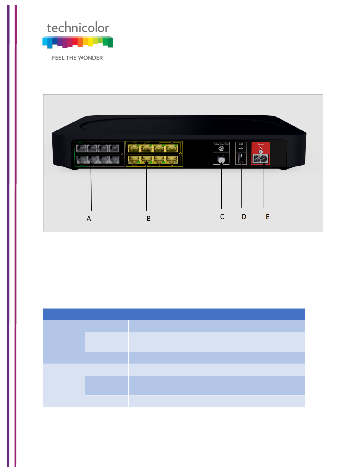
Back Panel
The following image depicts the back panel view of the CGA4131 TCH2-GA-TBR.
Figure 1.4
Telephone port (Item A)
Eight-line embedded digital voice adapter for wired telephony service.
Ethernet switch (Item B)
Eight 1000/100/10BASE-T Ethernet ports provide wired connectivity. The first 4 Ethernet
ports each can transfer up to 1 Gbps data, while the ports 5 to 8 can have a combined data
transfer speed of 1 Gbps. Each Ethernet port has two LEDs:
LED
LED Status
Description
Left LED
(Green)
Solid on
Connected to a Gigabit Ethernet device
Blinking
Connected to a Gigabit Ethernet device and
sending/receiving data
Off
Not connected to a Gigabit Ethernet device
Right LED
(Amber)
Solid on
Connected to a100Mbps/10Mbps device
Blinking
Connected to a 100Mbps/10Mbps device and
sending/receiving data
Off
Not connected to a 100Mbps/10Mbps device
Page 13
3/6/2018 Proprietary and Confidential - Technicolor 7
Cable port (Item C)
The CGA4131 complies with DOCSIS 3.0, 3.1 standards along with Packet Cable™
specifications to deliver high-end performance and reliability.
USB port (Item D)
USB port is used to connect USB devices.
Power inlet (Item E)
The power inlet (Power) allows connecting the power cord.
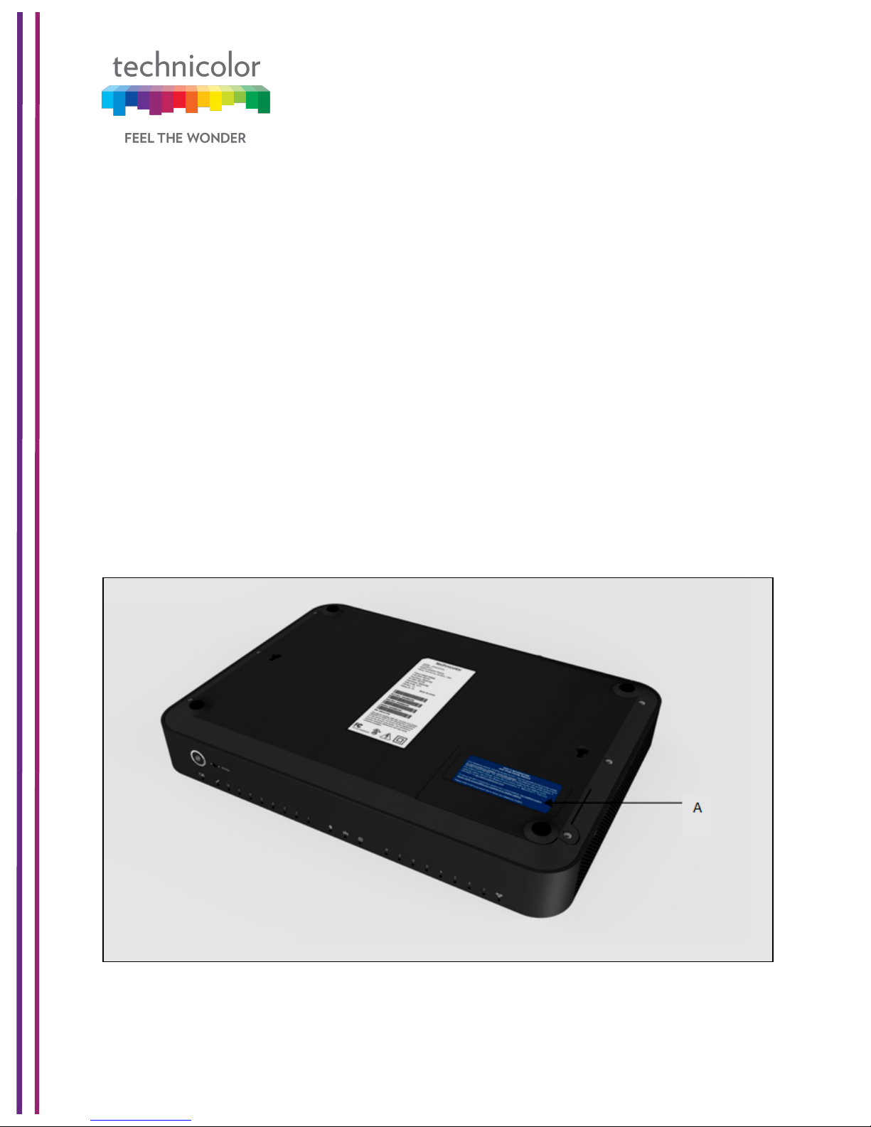
Bottom panel
The following images depict the bottom panel view of the CGA4131 TCH2-GA-TBR.
Figure 1.5 shows Bottom panel with Battery Compartment with door on (Item A).
Battery Slot (Item A)
Accommodates devices’ backup battery (optional)
Figure 1.5
Page 14
3/6/2018 Proprietary and Confidential - Technicolor 8
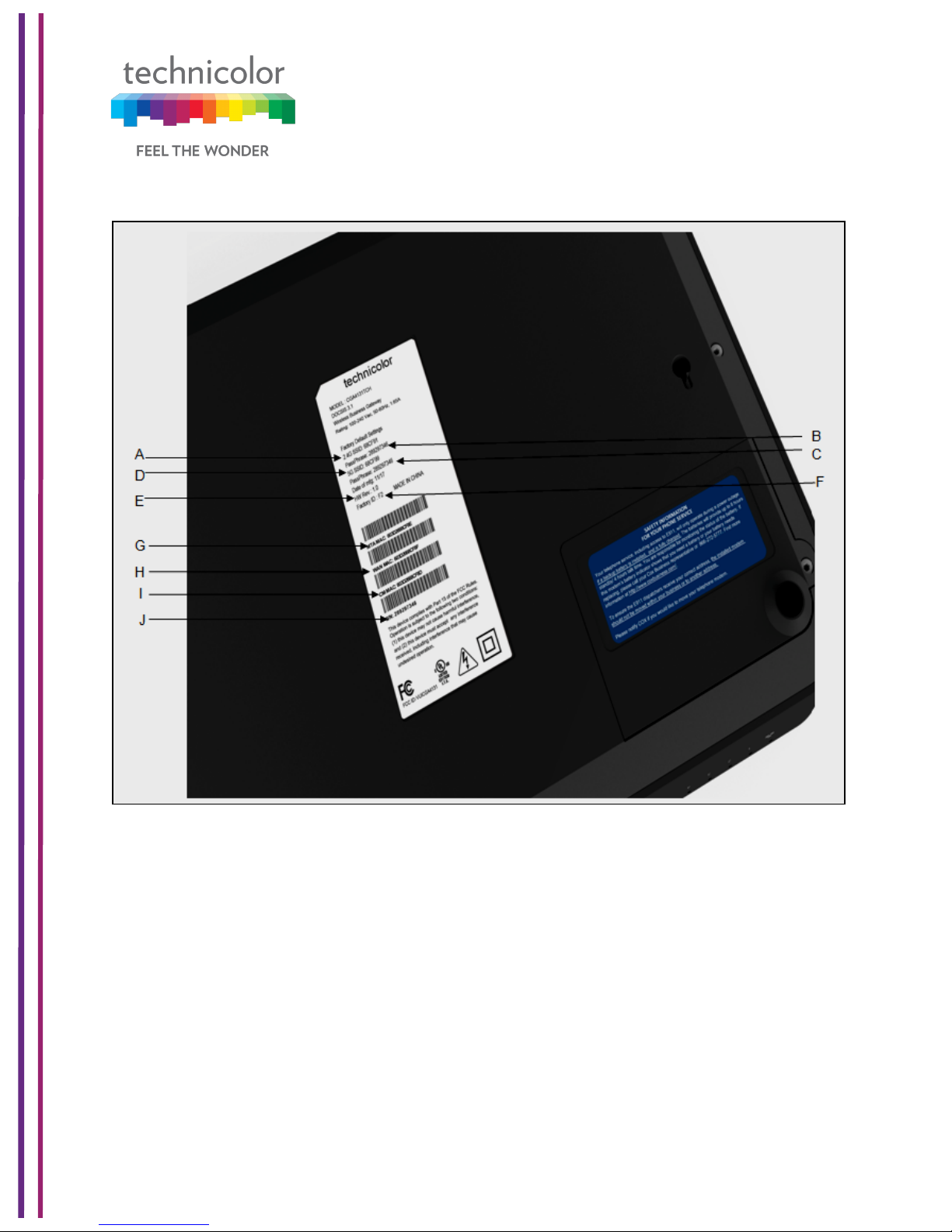
Figure 1.6 shows Bottom panel with labeling.
Figure 1.6
2.4GHz SSID (Item A)
Network Name (SSID) is the network name of the 2.4GHz access point. SSID is derived
from the Wi-Fi MAC address.
Passphrase of Device for2.4GHz (Item B)
PRE-SHARED KEY-Passphrase of Device for 2.4GHz.
Page 15

3/6/2018 Proprietary and Confidential - Technicolor 9
5GHz SSID (Item C)
Network Name (SSID) is the network name of the 5GHz access point. SSID is derived
from the Wi-Fi MAC address.
Passphrase of Device for5GHz (Item D)
PRE-SHARED KEY - Passphrase of Device for 5GHz
HW Rev (Item E)
This specifies the hardware revision of the device.
Factory ID (Item F)
This defines the factory ID of the device.
MTA MAC address (Item G)
This defines the MTA MAC address.
WAN MAC address (Item H)
This defines the WAN MAC address.
CM MAC address (Item I)
This defines the Cable Modem’s MAC address.
Serial Number of Device (Item J)
This defines the device’s serial number.
Page 16

3/6/2018 Proprietary and Confidential - Technicolor 10
2 WebUI Access Overview
This section explains the various access interfaces and access levels to CGA4131 Web UI.
There are 3 interfaces for the user/operator to connect to on the CGA4131 TCH2-GA-TBR:
• LAN (Default URL 192.168.0.1 on LAN side)
• Cable Modem (CM IP on the WAN side)
• eRouter (eRouter IP on the WAN side)
Apart from these 3 interfaces, there are 2 user levels – Home User and Advanced User.
The access to the various Web UI pages from various interfaces are determined by the
configuration of specific MIBs and the bit masking MIB to enable or disable a specific Web
UI page. The following table explains the Web UI pages accessible in these combinations:
MIB
MIB
value
Interface
Web UI pages accessible
tchCmWebAcc
essUserIfLevel.
home-user.lan
0
192.168.0.1 on
LAN PC
Allow Home user to login, show only System Page
1
192.168.0.1 on
LAN PC
Allow Home user to login, show only System Page
2
192.168.0.1 on
LAN PC
Allow Home user to login, show only System Page
3
192.168.0.1 on
LAN PC
Allow Home user to login, show only System Page
100
192.168.0.1 on
LAN PC
Allow Home user to login, show all pages with
bitmasking (tchCmWebAccessHomeWriteBitmask)
tchCmWebAcc
essUserIfLevel.
home-user.rfcm
-
Home User not
permitted to login
with CM IP on
WAN PC
Home User is not permitted to login with CM IP on WAN
PC
tchCmWebAcc
essUserIfLevel.
homeuser.wan-rg
0
eRouter IP on
WAN PC
Allow Home user to login, show only System Page
1
eRouter IP on
WAN PC
Allow Home user to login, show only System Page
2
eRouter IP on
WAN PC
Allow Home user to login, show only System Page
3
eRouter IP on
WAN PC
Allow Home user to login, show only System Page
100
eRouter IP on
WAN PC
Allow Home user to login, show all pages with
bitmasking (tchCmWebAccessHomeWriteBitmask)
tchCmWebAcc
essUserIfLevel.
adv-user.lan
0
192.168.0.1 on
LAN PC
Advanced user is not permitted to login from LAN side
1
192.168.0.1 on
LAN PC
Advanced user is not permitted to login from LAN side
2
192.168.0.1 on
LAN PC
Advanced user is not permitted to login from LAN side
3
192.168.0.1 on
LAN PC
Advanced user is not permitted to login from LAN side
Page 17

3/6/2018 Proprietary and Confidential - Technicolor 11
100
192.168.0.1 on
LAN PC
Advanced user is not permitted to login from LAN side
tchCmWebAcc
essUserIfLevel.
adv-user.rf-cm
0
CM IP on WAN
PC
Allow Advanced user to login, show only System Page
1
CM IP on WAN
PC
Allow Advanced user to login, show only System Page
2
CM IP on WAN
PC
Allow Advanced user to login, show only System Page
3
CM IP on WAN
PC
Allow Advanced user to login, show only System Page
100
CM IP on WAN
PC
Allow Advanced user to login, show all pages with bit
masking (tchCmWebAccessAdvancedWriteBitmask)
tchCmWebAcc
essUserIfLevel.
adv-user.wanrg
0
eRouter IP on
WAN PC
Allow Advanced user to login, show only System Page
1
eRouter IP on
WAN PC
Allow Advanced user to login, show only System Page
2
eRouter IP on
WAN PC
Allow Advanced user to login, show only System Page
3
eRouter IP on
WAN PC
Allow Advanced user to login, show only System Page
100
eRouter IP on
WAN PC
Allow Advanced user to login, show all pages with
bitmasking (tchCmWebAccessAdvancedWriteBitmask)
The Web UI pages available for home user and the advanced user access levels can be
different. They are defined by the access Level MIB and bit masking MIBs
(tchCmWebAccessHomeWriteBitmaskand tchCmWebAccessAdvancedWriteBitmask).The
bit masking information is also stored in the config file. They can also be modified by the
SNMP MIBs. Please see Appendix 2 for examples of configuring these bitmask MIB
elements.
The user is directed to login page to login with default system credentials (admin /
password). For the advanced user, the user name is admin and the password would be the
generated password of the day (POTD).
CM Config file snippet for POTD configuration
SnmpMibObject tchCmWebAccessAdvancedType.0 Integer 2; /* potd */
SnmpMibObject tchCmWebAccessAdvancedPassword.0 HexString 0x272a73bdb4945eddc88f6a66198c1056;
The Web UI has an idle timeout of 15 minutes. The user needs to re-login to access the
Web UI after the timeout.
Page 18
3/6/2018 Proprietary and Confidential - Technicolor 12
3 Initial Configuration and Setup
The CGA4131 is configured using the Web UI.
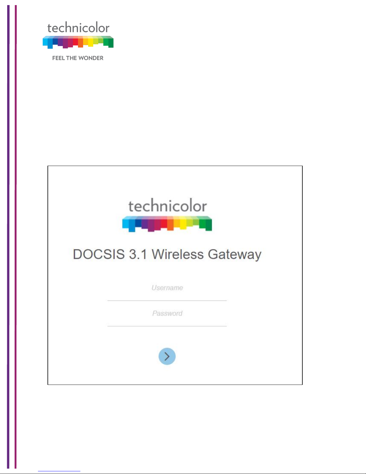
3.1 Accessing the Web UI
CGA4131 Web UI can be accessed through the various interfaces (LAN IP, CM IP or the
eRouter IP) as explained in the previous section. The gateway prompts the user to enter the
username and password.
Figure 3.1
The various pages on the Web UI would be accessible once the credentials are accepted.
Page 19

3/6/2018 Proprietary and Confidential - Technicolor 13
4 Web UI Guide
The following table describes the web pages available to the users. Availability of these
pages is defined by the Web UI access levels configured as per the previous section.
Top Tab
Sub-tab
Status
Overview
Gateway
Local Network
Wireless
DOCSIS Status
DOCSIS Signal
DOCSIS Log
Spectrum Analyzer (WAN:- CM Side details for login
work )
System
Connection
Devices
LAN
WAN
Routing
Modem
MTA
Network Time
Wireless
Radio
Security
Advanced
Guest Network
MAC Control
WPS
QoS
Hotspot
Security
Firewall
IP Filter
Device Filter
Page 20

3/6/2018 Proprietary and Confidential - Technicolor 14
Access Control
Service Filter
VPN
Email Settings
Report
Application
Port Forward
Port Trigger
Port Filter
DDNS
DMZ
UPnP
IP Passthrough
SIP ALG
Administration
User
Remote Access
Backup & Restore
Reboot & Reset
Troubleshooting
Remote Log
Diagnostic
System
Interface
Network
Wireless
Clients
Internet
!
Page 21
3/6/2018 Proprietary and Confidential - Technicolor 15
5 Status Pages
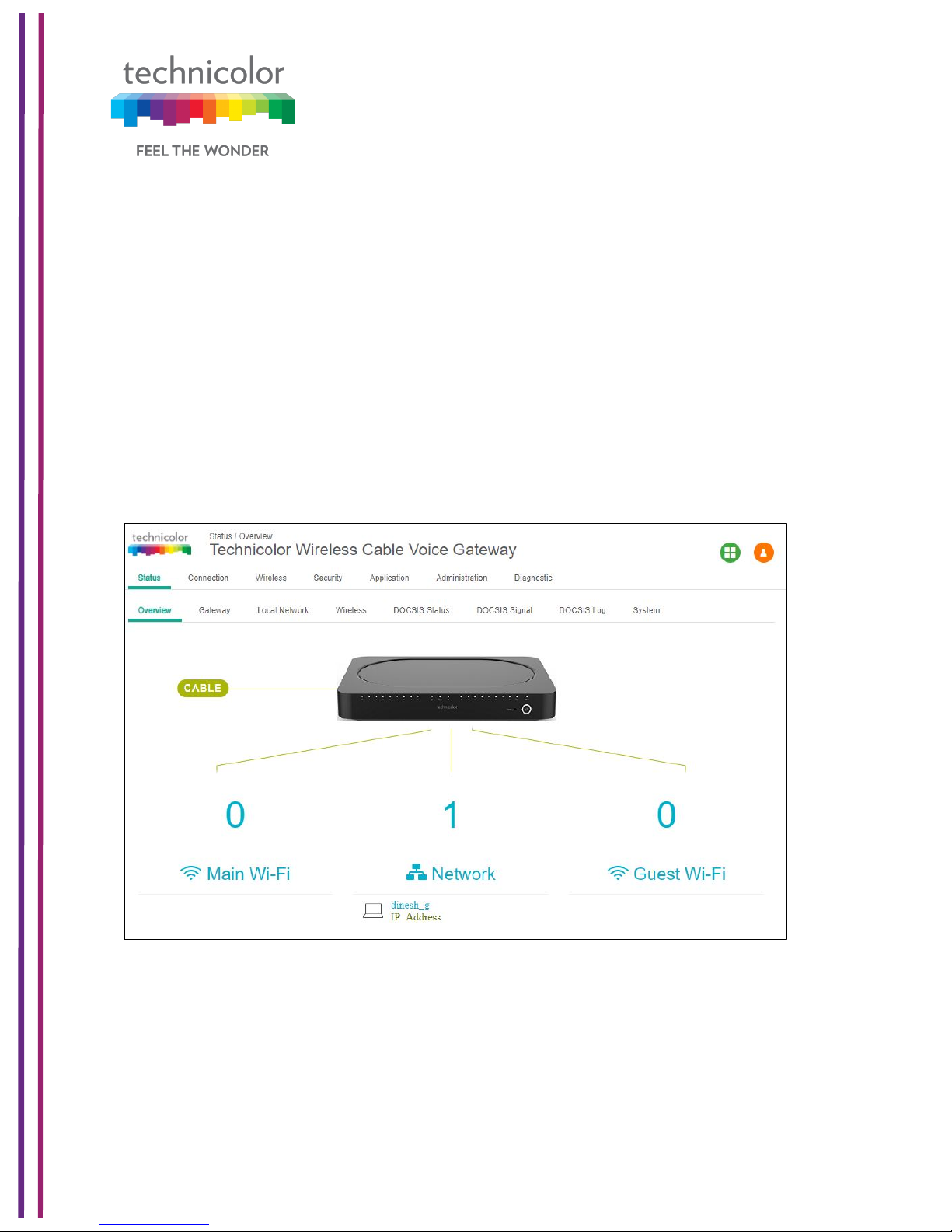
5.1 Overview
Status Tab / Overview
The Overview page under the Status page provides the high level view of the Business
Gateway. It displays the connections on the Wi-Fi, LAN and Guest Wi-Fi networks.
• Main Wi-Fi Displays the connected Wi-Fi (WLAN) Clients with their Host Name and
IP address.
• Network Displays the connected Wired (LAN) Clients with their Host Name and IP
address.
• Guest Wi-Fi Displays the clients connected to Guest Wi-Fi.
Figure 5.1
Page 22
3/6/2018 Proprietary and Confidential - Technicolor 16
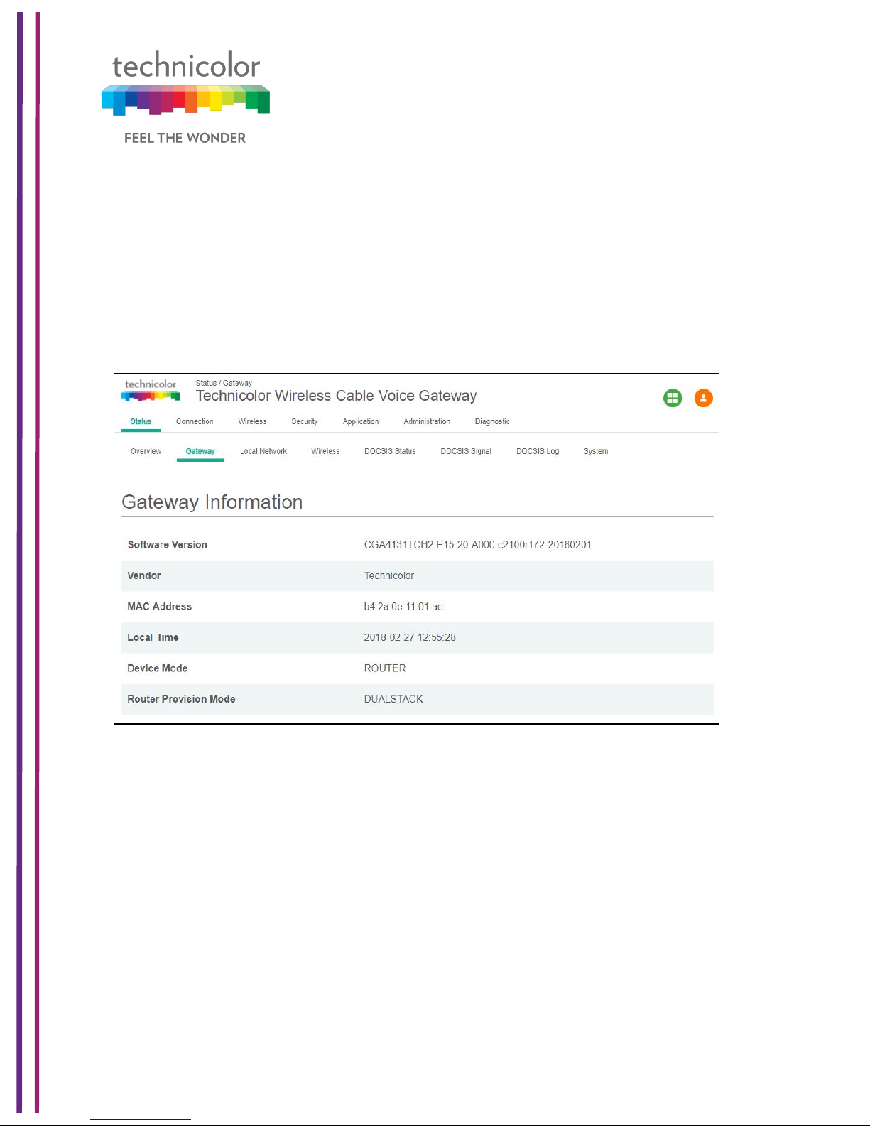
5.2 Gateway
Status Tab / Gateway
Click on the Status tab then click on Gateway. The page displays Gateway information and
the IP Network information.
The Gateway Information section shows the Software Version, Vendor Name, eRouter MAC
address, Device Mode, Router Provision Mode and Local Time set in the device as shown
below:
Figure 5.2
The IP connectivity information provided in the page includes eRouterIP Address, Subnet
Mask, DNS and default Gateway Information for the IPv4 and IPv6 connections. The details
are displayed as given below:
Page 23
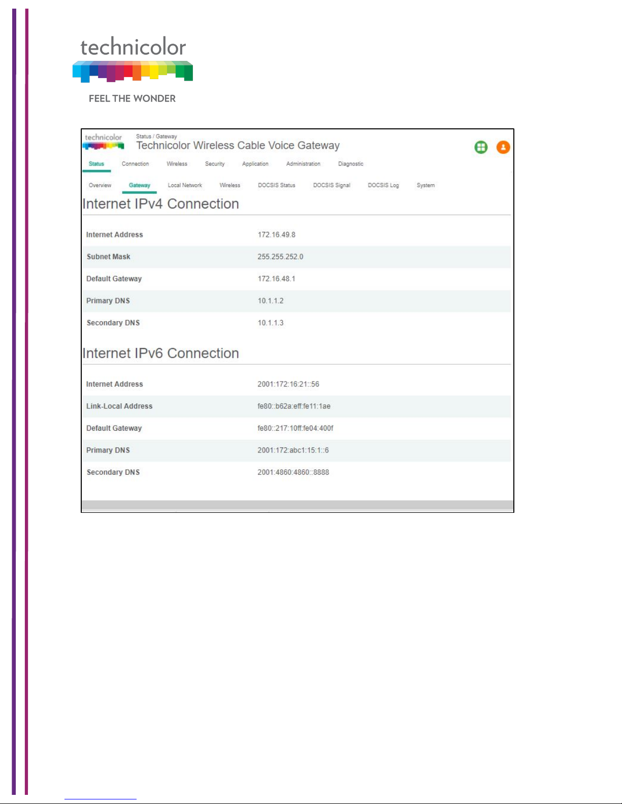
3/6/2018 Proprietary and Confidential - Technicolor 17
Figure 5.3
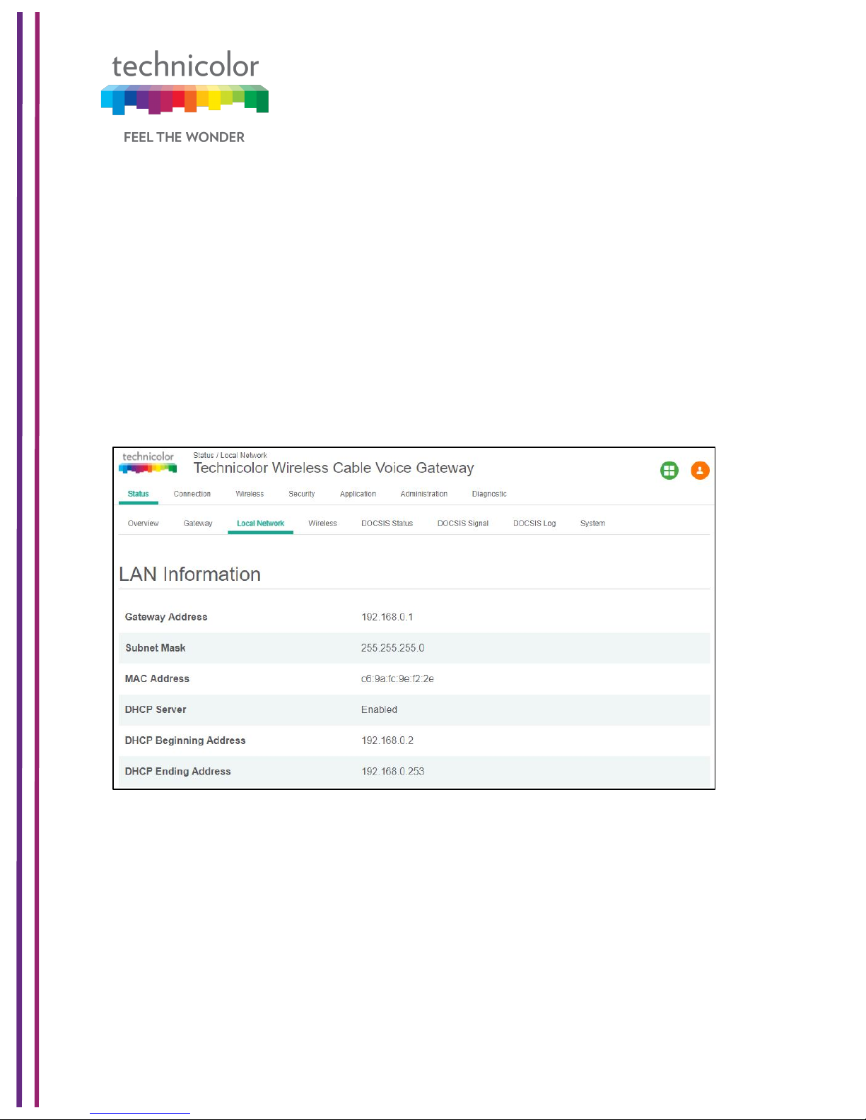
5.3 Local Network
Status Tab / Local Network
Click on the Status tab then click on Local Network. The Local Network page will display the
LAN information seen by the user.
LAN Information:
This section displays the configuration of DHCP addresses for the home user on the LAN
side, Information such as the Gateway Address, Subnet Mask, MAC Address, DHCP Server,
DHCP Beginning Address and DHCP Ending Address are displayed here.
Page 24
3/6/2018 Proprietary and Confidential - Technicolor 18
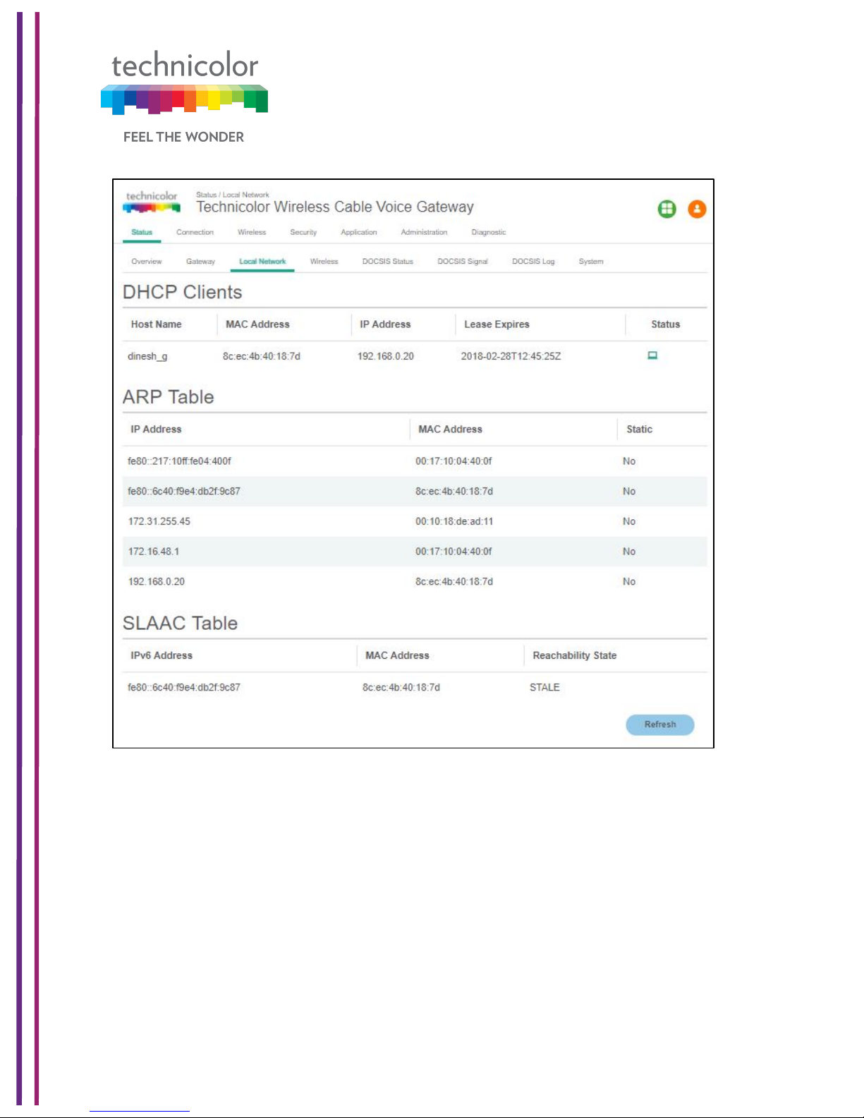
DHCP Clients:
The connected clients to the gateway via either Ethernet or Wi-Fi will be displayed in this
table.
ARP Table:
The ARP Table section displays ARP information about connected clients. When a client is
configured for static IP, the static option will be shown as Yes.
SLAAC Table Information:
Stateless Auto Configuration (SLAAC) is a feature offered by the IPv6 protocol. It allows the
various devices attached to an IPv6 network to connect to the Internet using the Stateless
Auto Configuration without requiring any intermediate IP support in the form of a DHCP
server. The SLAAC Table section displays details about IPv6 Address, the corresponding
MAC Address and Reachability States information.
Figure 5.4
Page 25
3/6/2018 Proprietary and Confidential - Technicolor 19
Figure 5.5
When in IPv6 mode or Dual Stack mode, the DHCP Client table includes IPv6 related status
and type information.
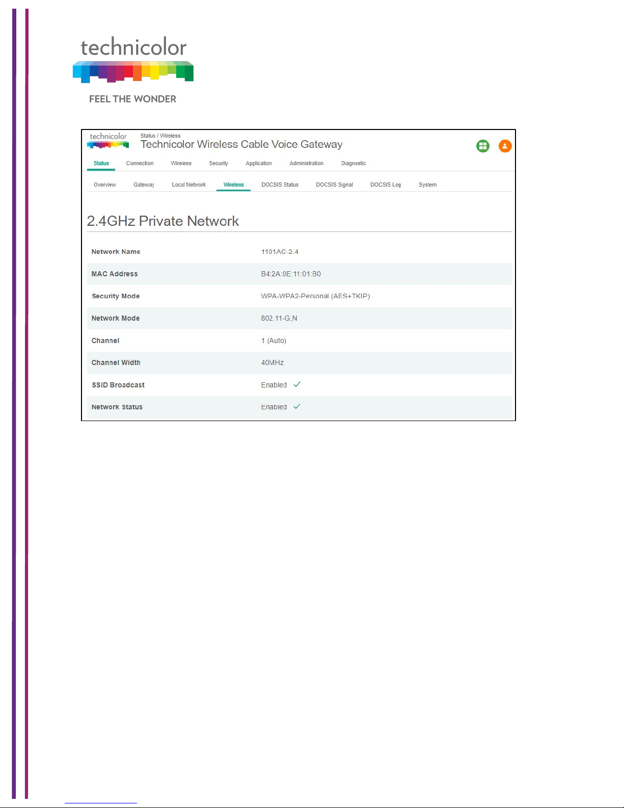
5.4 Wireless
Status Tab / Wireless
Click on the Status tab then click on the Wireless tab. The page provides wireless network
information, including the Network Name (SSID), MAC Address, Security Mode, Network
Mode, Channel, Channel Width, SSID Broadcast and Network Status for 2.4GHzand 5GHz.
Page 26
3/6/2018 Proprietary and Confidential - Technicolor 20
Figure 5.6
Page 27

3/6/2018 Proprietary and Confidential - Technicolor 21
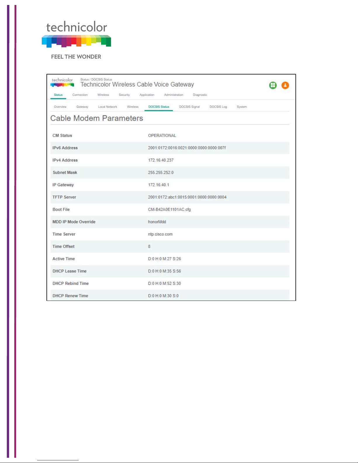
5.5 DOCSIS Status
This page displays status information about the DOCSIS connection.
Status Tab / DOCSIS Status
Click on Status tab, and then click on DOCSIS Status. DOCSIS Status page explains the
network connectivity and Cable Modem status. The following information is displayed:
Cable Modem Parameters:
This section displays information about the RF upstream Bonding, including CM Status,
Active Time, IPv6 Address, IPv4 Address, Subnet Mask, IP Gateway, TFTP Server, Time
Server, Time Offset, DHCP Lease Time, DHCP Rebind Time and DHCP Renew parameters.
• CM Status – possible cable modem status states are other, notReady,
notSynchronized, phySynchronized, usParametersAcquired, rangingComplete,
ipComplete, todEstablished, securityEstablished, paramTransferComplete,
registrationComplete, operational andaccessDenied.
• Active time - The time since the network management portion of the system was last
re-initialized.!
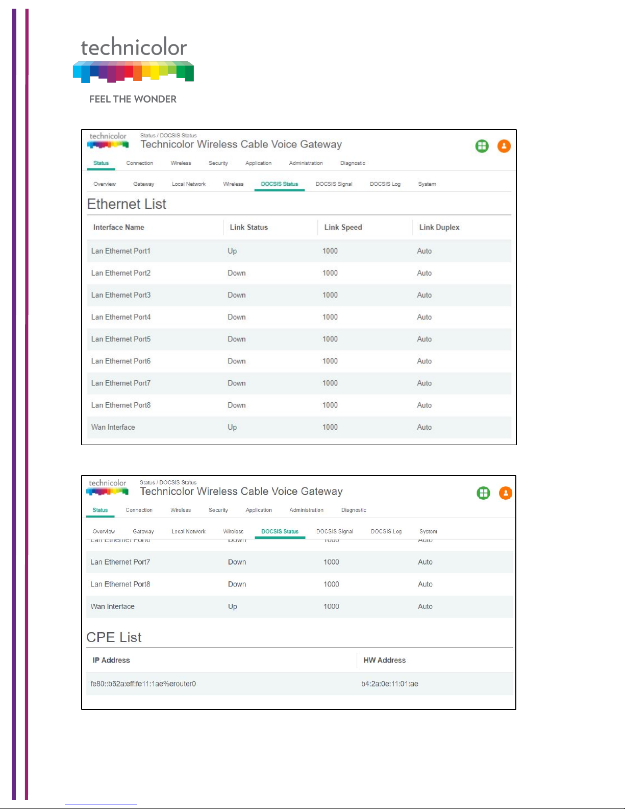
Ethernet List:
This section displays information about the Ethernet ports and any devices connected to
them and show Interface Name, Link Status, Link Speed and Link Duplex parameters.
• Interface name displays Displays the port number in general (Ethernet 1 / Ethernet
2, etc.)
• Link Status - If there is any activity on the Link (Any Device connected) the Link
Status is shown as "UP", otherwise it is shown as "DOWN"
• Link Speed and Link Duplex - Speed of 10/100/1000 and is it half duplex, full duplex
or Auto
CPE List:
• This section displays the IP Address (IPv4 and/or IPv6) and MAC Address of the
devices connected.
The following figures provide these details displayed in the page:
Page 28
3/6/2018 Proprietary and Confidential - Technicolor 22
Figure 5.7
Page 29
3/6/2018 Proprietary and Confidential - Technicolor 23
Figure 5.8
Figure 5.9
Page 30

3/6/2018 Proprietary and Confidential - Technicolor 24
5.6 DOCSIS Signal
Status Tab / DOCSIS Signal
The DOCSIS Signal page displays the plant information on which the modem is connected.
Click on the Status tab then click on DOCSIS Signal.
Upstream Bonding:
This section displays information about RF upstream Bonding, including upstream channel
ID, Upstream Lock Status, Channel Type, Centre Frequency, Band Width, Modulation, and
Power Level (Tx Power level at gateway for the particular channel).
• Upstream Bonding - Number of channels locked to upstream which can be used for
upstream data transfer
• Upstream channel ID - The CMTS identification of the upstream channel
• Upstream Lock Status- Displays Locked if QAM and FEC are locked (indicates that
the channel is usable)
• Upstream Channel Type - Displays if it is a SC-QAM channel (Phy type 3) or a
OFDMA channel (Phy type 5)
• Upstream CenterFrequency - The center of the frequency band associated with this
upstream interface. Displays 0 if the frequency is undefined or unknown.
• Upstream Band Width-The bandwidth of this upstream interface as configured on
the CMTS (Generally 1.6MHz, 3.2Mhz or 6.4MHz)
• Upstream Modulation - Displays the modulation used on upstream ATDMA, TDMA,
SCDMA or MTDMA
• Upstream Power Level- Transmit power level at which the cable modem is
transmitting on the respective channel
Downstream Bonding:
This section displays information about the RF downstream bonding with downstream
channel ID, Downstream Lock status, Downstream Bond Status, Downstream Channel
Type, Downstream Centre Freq., Downstream Band Width, Modulation, Power Level (Rx
power level at the gateway for the specific channel) and SNR Level.
• Downstream Channel ID-The CMTS identification of the downstream channel within
this particular MAC interface. If the interface is down, displays the most current value.
If the downstream channel ID is unknown, 0 is displayed.
• Downstream Lock Status -Displays Locked if QAM and FEC are locked (indicates
that the channel is usable)
• Downstream Bonding-Number of channels locked to downstream which can be used
for downstream data transfer
• Downstream Channel Type -Displays if it is a SC-QAM channel or a OFDM channel
• Downstream Centre Frequency-The center of the downstream frequency associated
with this channel
• Downstream Band Width -The bandwidth of this downstream channel. Most
implementations are expected to support a channel width of 6 MHz (North America).
Page 31

3/6/2018 Proprietary and Confidential - Technicolor 25
• Downstream Channel Modulation -The modulation type associated with this
downstream channel. If the interface is down, it displays "unknown", else it will be
either QAM64 or QAM256 based on CMTS configuration
Figure 5.10
Error Codewords:
This section displays Error Codewords, the information about the Channel ID, Unerrored,
Correcteds and Uncorrectables.
Page 32

3/6/2018 Proprietary and Confidential - Technicolor 26
Figure 5.11
Page 33

3/6/2018 Proprietary and Confidential - Technicolor 27
5.7 DOCSIS Log
Status Tab / DOCSIS Log
The page displays information about the DOCSIS Log including Time, ID, Level and
Description for the entries. Click on the Status tab then click on DOCSIS Log. The number
of entries to be listed can be selected from the drop-down menu corresponding to the “Show
entries” field.
Figure 5.12
5.8 Spectrum Analyzer
CGA4131 Business Gateway supports the Spectrum Analyzer feature, which can monitor a
cable plant in real-time. This feature can provide details on the spectrum either via the Web
UI or via SNMP MIBs.
There are 3 main features that the spectrum analyzer supports: Run, Hold and Preset.
• A user can click the RUN button and would see real-time measurements being sent
by the tuner to the HTTP server and being displayed on the webpage.
• A user could also click HOLD to freeze the spectrum at the last measurement to
troubleshoot any issues.
• Clicking PRESET would set the defaults and disable spectrum analyzer.
Page 34

3/6/2018 Proprietary and Confidential - Technicolor 28
Status Tab / Spectrum Analyzer
Spectrum Analyzer view is only available for the CM side login.
Figure 5.14
By default, the frequency settings have START and STOP at 0 and 1000MHz (1GHz) by
default and the center being at 500MHz.
Run - Spectrum Analyzer Graph will start with set parameter from the following options:
• Frequency - show 3 options to set the X-axis starting Point (START), Ending
point (STOP) and Middle point (CENTER)
• Span - The duration of Frequency can be varied. For ex: 100 MHz the scale of
X-axis is 10 units.
• AMPLITUDE - To set the Y-axis (dBm) upper limit values. The graph will adjust
accordingly
• BW – Bandwidth option shows 2 options Vid Avg and Peak Hold for bandwidth.
Either one of them can be "ON" at any time.
• MEASUREMENTS – This option helps to switch the feature "ON" and get the
power values (dBm) at a particular Frequency. The value should be less than the
span value.
Page 35

3/6/2018 Proprietary and Confidential - Technicolor 29
• CUSTOM - After clicking Birth Certificate Capture button, It'll be showing
"Capture Started..." and wait for the "Capture Complete!" message. After that
graph will start again.
A user can then change the various parameters to suite the required measurements using
the Web UI options.
5.8.1 SNMP provisioning for Spectrum Analyzer
The spectrum analyzer feature can be controlled via SNMP in order to collect the data from
the demodulators as well as change various parameters. The following MIBs are supported:
tchCmSpectrumAnalysis!
tchCmSpectrumAnalysisFreq ue ncy!!
! tchCmSpectrumAnalysisAm p litude Da ta!!
! tchCmSpectrumAnalysisEnable!!
! tchCmSpectrumAnalysisInactivityT im eo ut!!
! tchCmSpectrumAnalysisDiagn o sticM o de !!
! tchCmSpectrumAnalysisFirstSeg m en tCe nte rFre qu en cy!
! tchCmSpectrumAnalysisLastS egm e ntC en terF req ue nc y!!
! tchCmSpectrumAnalysisSegmentFrequencySpan!!
! tchCmSpectrumAnalysisBinsP erS egm e nt!!
! tchCmSpectrumAnalysisW ind ow F un ction !!
! tchCmSpectrumAnalysisEqu ivalen tN oise Ban d w idth!
5.9 System
Status Tab / System
This page displays further information on the DOCSIS connection, system software and
hardware configuration. Click on the Status tab then click on System.
DOCSIS State:
This section displays information about the DOCSIS State including Initialize Hardware,
Acquire Downstream Channel, Upstream Ranging, DHCP Bound, Set Time-of-Day,
Configuration File Download, Registration and CM Status.
System Software:
This section displays information about the System Software including the Model Name,
Vendor, Serial Number, Software Version, Firmware File Name, Firmware Build Time,
Bootloader Version, Core Version, Local Time and System Uptime.
System Hardware:
This section displays information about the System Hardware including the Hardware
Version, Processor Speed, Flash Size, Total Memory and MAC Address.
The DOCSIS State page is displayed below:
Page 36

3/6/2018 Proprietary and Confidential - Technicolor 30
Figure 5.14
Page 37

3/6/2018 Proprietary and Confidential - Technicolor 31
The System Software information is provided as shown below:
Figure 5.15
Page 38

3/6/2018 Proprietary and Confidential - Technicolor 32
The System Hardware information is provided as shown below:
Figure 5.16
Page 39

3/6/2018 Proprietary and Confidential - Technicolor 33
6 Connection
Connection Page displays the status and details of client devices that are connected to the
gateway. The page also allows users to configure DHCP IP address for the LAN clients or
add a device and assign it a static IP address. It also provides an option to configure the
gateway in router or bridged mode.
6.1 Devices
Connection Tab /Devices
The Connection/Device page displays all clients that are connected to the private and the
public/guest network. The page also displays the details of the connected device like
Interface type, connection type, device name and the IP Address.
Click on Connection tab then click on Devices in the Web UI. The devices page appears
populated with the information below:
Figure 6.1
6.2 LAN
Connection Tab / LAN
Page 40

3/6/2018 Proprietary and Confidential - Technicolor 34
Click on the Status tab then click on Local Network. The page displays details about the LAN
configuration. The page also provides options to configure the LAN connections.
LAN Information:
The LAN Information section on the Local Network page displays details about the Gateway
Address, Subnet Mask, DHCP details (Server, DHCP Beginning Address and DHCP Ending
Address) and DNS details.
Clients connected to the LAN side, which are connected via wired or wireless, get IP
addresses from the DHCP server running on the gateway. The beginning and end IP
address define how many clients can be connected to the gateway (or the number of valid
IP addresses that can be assigned).The gateway address of 192.168.0.1 is the default IP
address; it is user configurable.
The user can modify the LAN configuration including the number of IP addresses. If a client
needs to be assigned with a static address, the user must select the static IP option and
enter the MAC address of the client that needs the static IP address.
The life time of the DHCP address is defined in the DHCP lease time and again it is user
configurable. By default, the lease time is 86400 seconds.
The eRouter supports DNS Passthrough - The gateway implements a Dnsmasq, which
caches the DNS entries for the LAN requests. In case the entry is not present, the gateway
would resolve them with DNS server in the WAN network.
Page 41

3/6/2018 Proprietary and Confidential - Technicolor 35
Figure 6.2
6.2.1 SNMP provisioning for LAN
The following table depicts the LAN Configuration MIBs supported:
No
MIB
Description
1
rdkbRgIpMgmtLanTable
LAN configuration Table
2
rdkbRgIpMgmtLanDhcpServerTabl
e
DHCP Server Details
3
rdkbRgIpMgmtDnsServerTable
DNS Server Details
4
rdkbRgIpMgmtApplySettings
Set the changes to LAN entry
Page 42

3/6/2018 Proprietary and Confidential - Technicolor 36
6.3 WAN
6.3.1 User provisioning for WAN
Connection Tab / WAN
The page displays WAN configuration information. Click on the Connection tab then click on
the WAN tab. The page also allows the setting of WAN configuration - Working Mode (Router
Mode, Bridged Mode), Connection Mode (DHCP, Static IP), Host Name and Domain Name.
Figure 6.3
When the gateway WAN provisioning is enabled with DHCP, IPv4 and IPv6 DHCP client on
the gateway will initiate DHCP request to get the eRouter / WAN IP for the gateway. In case
of DHCP v6, the eRouter IP is got from the MSO network through IP Prefix delegation.
Page 43

3/6/2018 Proprietary and Confidential - Technicolor 37
6.3.1.1 Working Mode
The gateway can be setup in Bridge or Router mode using this drop-down option, which
allows specific configuration of the device to Router or Bridge Mode for access and security.
In Router mode, routing functionality is enabled in the gateway. All the LAN and Wi-Fi clients
get local IP addresses from the DHCP server. The NAT functionality in the gateway
translates the private IP to the eRouter IP for external Internet access. When the gateway is
provisioned with dual stack, then DHCP v6 and v4 servers run in the gateway for the LAN
clients.
In Bridge mode, the routing functionality is disabled (DHCP and NAT functionalities are
similarly disabled).All LAN clients receive public IPs from the MSO .The Wi-Fi network is not
enabled in Bridge mode.
Router Mode:
The default option is Router Mode. Routing functionality is enabled with Wi-Fi and LAN set
to active. The management IP address will change LAN configuration (such as from x.x.x.x
to y.y.y.y. For instance, it may change from 10.0.0.1 to 192.168.0.1.)
Figure 6.4
Bridge Mode:
If Bridge Mode option is selected, the device reboots automatically and operates in Bridge
Mode after reboot. Routing functionality is disabled. All 8 LAN ports remain active in Bridge
mode and receive a bridged/public IP when a client is connected. The management IP
address will change to 192.168.100.1. Please record this address for future reference to
switch back to Router Mode via the Connection page. The device can also be reverted to
Router mode by factory reset via front panel switch.
Page 44

3/6/2018 Proprietary and Confidential - Technicolor 38
!
CAUTION: BRIDGE MODE MAY PREVENT MULTIPLE DEVICES FROM ACCESSING
THE INTERNET.
6.3.1.2 SNMP provisioning for Bridge Mode
To configure the device in Bridge mode, set the corresponding interface instance of
rdkbRgIpMgmtLanMode.32 to bridge (1).
6.3.1.3 Connection Mode
There are 2 connection modes possible – DHCP or Static IP. When DHCP is selected, the
WAN IP (eRouter IP) is configured automatically by the MSO DHCP Server.
In case of static IP, the details (IP address, Subnet Mask, Default Gateway, DNS
configuration, MTU, etc.) needs to be obtained from the MSO and entered through the Web
UI.
Figure 6.5
Provisioning WAN IP through DHCP
Page 45

3/6/2018 Proprietary and Confidential - Technicolor 39
When the WAN Connection Mode is selected as DHCP, no more user settings will be
available to configure WAN IP. The WAN side will receive an IP address as per the rules
specified in the DHCP configuration of the MSO/ISP.
Provisioning with Static IP
The Static IP for WAN interface is provided by the Service Provider.
Figure 6.6
While configuring the Connection Mode as Static IP, the user needs to configure the
following:
Internet IP Address
The gateway's IP address, as seen from the Internet
Subnet Mask
The gateway's Subnet Mask
Default Gateway
Page 46

3/6/2018 Proprietary and Confidential - Technicolor 40
The IP address of the service provider's server
Primary DNS (Required) and Secondary DNS (Optional)
Primary and Secondary DNS (Domain Name System) server IP addresses provided by the
service provider. At least one is required.
Host Name (Optional)
The Host Name field is optional but may be required by some Internet Service Providers.
The default host name is the model number of the device.
Domain Name (Optional)
Enter the local domain name for the Network.
Figure 6.7
Setting the values of different parameters (Working mode, Connection Mode, Host name,
Domain name):
• Click on the corresponding drop down menu and select the required values.
• Press Save.
6.3.2 SNMP provisioning for WAN
Page 47

3/6/2018 Proprietary and Confidential - Technicolor 41
6.3.3 Dual Stack Router
In dual stack configuration, eRouter will have both an IPv4 and IPv6address.This can be
utilized with a dual stack for the cable modem to make sure that the gateway can support a
mix of devices that support IPV4 and IPv6.
To set eRouter in Dual IP stack (IPv4 and IPv6), set TLV 202 to Dual or set
rdkbRgDeviceMode to dualstack (5).
6.3.4 eSAFE
The eRouter is specified as an Embedded Service/Application Functional Entity (eSAFE)
device as defined in DOCSIS specifications and is implemented in conjunction with a
DOCSIS cable modem device. The below MIBs object provides visibility to control over the
initialization Mode and a mechanism to soft reset DOCSIS eRouter eSAFE element:
• esafeErouterInitModeControl - The esafeErouterInitModeControl object is used
to change the eRouter Mode after the eRouter has initialized.Whenever the value of
esafeErouterInitModeControl is changed from the default of
honoreRouterInitMode (5) via an SNMP SET, the eRouter MUST override the
eRouter Initialization Mode encoding encapsulated in the CM configuration file and
use the value of the esafeErouterInitModeControl. The other possible values for
esafeErouterInitModeControl are ipDisabled (1), ipv4Only (2), ipv6Only (3) and
ipv4AndIpv6 (4).
• esafeErouterSoftReset - Setting esafeErouterSoftReset to true (1) causes the
eRouter to perform a soft reset. An SNMP GET/GETNEXT of this object always
returns a value of false (2).
• esafeErouterOperMode - This object provides visibility to the current mode of
operation of the DOCSIS eRouter eSAFE element. If the value of this object is
disabled (1), the eRouter eSAFE element has been administratively Disabled. If the
value of this object is ipv4OnlyFwding(2), the eRouter eSAFE element is currently
operating with the IPv4 protocol stack operational, is forwarding IPv4 traffic, and is
not running an IPv6 protocol stack and not forwarding IPv6 traffic. If the value of this
object is ipv6OnlyFwding(3), the eRouter eSAFE element is currently operating with
the IPv6 protocol stack operational, is forwarding IPv6 traffic, and is not running an
IPv4 protocol stack and not forwarding IPv4 traffic. If the value of this object is
ipv4AndIpv6Fwding(4), the eRouter eSAFE element is currently operating with both
the IPv4 protocol stack and IPv6 protocol stack operational, and is forwarding IPv4
and IPv6 traffic. If the value of this object is noIpv4AndNoIpv6Fwding (5), the eRouter
is currently operating with neither the IPv4 nor IPv6 protocol stack running.
Page 48

3/6/2018 Proprietary and Confidential - Technicolor 42
6.4 Routing
The routing view enables the user to configure RIP.IGMP Proxy can also be enabled or
disabled from this view.
Connection Tab / Routing
Click on the Connection tab then click on Routing. This page displays Routing setup
information for RIP. Here, IGMP Proxy can be displayed and set.
Figure 6.8
6.4.1 Enable / Disable IGMP Proxy
IGMP Proxy is used to enable multicast feature support. Users can enable or disable the
IGMP Proxy using by selecting the button on the page.
Page 49

3/6/2018 Proprietary and Confidential - Technicolor 43
Figure 6.9
6.4.2 RIP
The Routing Information Protocol (RIP) defines a way for routers, which connect networks
using the Internet Protocol (IP), to share information about how to route traffic among
networks. RIP is classified by the Internet Engineering Task Force (IETF) as an Interior
Gateway Protocol (IGP), one of several protocols for routers moving traffic around within a
larger autonomous system network -- e.g., a single enterprise's network that may be
comprised of many separate local area networks (LANs) linked through routers.To configure
the RIP feature, the user needs to provide the following information:
• RIP (enable disable),
• Send Version (Version 2 recommended)
• Receive Version (Version 2 recommended)
• Update Interval (duration between route updates – default 30 seconds)
• Default Metric
• Authentication Type
• Authentication Key
• Authentication ID
• Neighbour Address(Next hop address)
Connection Tab / Routing
Click on the Connection tab then click on the Routing tab. The gateway will display the
information below.
Page 50

3/6/2018 Proprietary and Confidential - Technicolor 44
Figure 6.10
6.4.3 User provisioning for RIP
To change the configuration, the user needs to click on the parameters and change the
values appropriately and press the save button provided in the page. The specific parameter
configurations are explained below:
• RIP can be enabled by selecting the RIP Enable option.
• The send version and receive version can be either 1 or 2. If no version is selected,
version 1 would be sent; however both version 1 and 2 can be received
• Update interval configures the time interval between route updates – default value is
30 seconds.
• Metric is a parameter used by RIP in case there are multiple routes were identified
to the same destination. The protocol uses the shortest path to route the packets to
such destinations and it is determined by the metric parameter. Default value is 1.
• The user needs to select the Authentication type (Text / MD5), Key and ID to
complete the authentication configuration.
Page 51

3/6/2018 Proprietary and Confidential - Technicolor 45
• Neighbor Address: Defines a neighboring device to which the routing information is
exchanged.
6.4.4 SNMP provisioning for Advanced Routing Feature
MaxCPE settings (specific to CM config file)
MaxCPE “N” where “N” is the number of clients (CPE) that can be connected.
In case the customer network is behind a router (Example with customer router), customer
subnet needs to be advertised back to the IP backbone network (static configuration).
6.5 Modem
Connection Tab / Modem
Click on the Connection tab then click on the Modem tab. The gateway will display the
various modem parameters:
• The Downstream Frequency is the frequency at which the modem is locked with
the CMTS during channel scan
• Scan Start Frequency is the frequency at which the modem tries to lock first, as this
will be the frequency at which the modem was able to connect last time and is saved
as favorite channel.
• Upstream Channel ID is shows locked Upstream Channel Id for Cable Modem.
Figure 6.11
6.6 MTA
This page displays the MTA line status and the logs.
Page 52

3/6/2018 Proprietary and Confidential - Technicolor 46
Connection Tab / MTA
Click on the Connection tab then click on the MTA. The gateway will display the line status
for the 8 MTA line - the status could be shown as onhook / offhook if the MTA is provisioned
on the device.
Figure 6.12
The logs will show the details of log generated during MTA operation that includes call
status, error message that would be helpful for debugging.
Page 53

3/6/2018 Proprietary and Confidential - Technicolor 47
Figure 6.13
6.7 Network Time
Connection Tab / Network Time
Click on the Connection tab then click on the Network Time tab. The network time page will
display the various parameters related to current time, NTP server, etc. Options to configure
Auto Daylight Saving and Time Zone are provided in this view.
Page 54

3/6/2018 Proprietary and Confidential - Technicolor 48
Figure 6.14
The user can change the configurations and press the Save button in the page to change
these parameters.
Page 55

3/6/2018 Proprietary and Confidential - Technicolor 49
7 Wireless
The CGA4131 TCH2-GA-TBRalso serves as an 802.11 wireless access point (AP).A
complete set of the wireless configuration pages described below is presented under the
Wireless tab in the Web UI. This section contains the essential configuration items for a
wireless network.
7.1 Radio
Wireless Tab / Radio
Click on the Wireless tab then click on the Radio tab. The page displays Radio setup
information at 2.4GHz and 5GHz. Here a user can set and display Wireless Network
(2.4GHz and 5GHz) information as for Wireless Interface, Network Name, Network Mode,
Channel Width, Channel, MAC Address, Scan Nearby AP.
Figure 7.1
Page 56

3/6/2018 Proprietary and Confidential - Technicolor 50
Figure 7.2
Wireless Interface:
The wireless interface can be enabled or disabled with this option.
Network Name:
The Network Name can either be set or displayed under this option. The user can also
prevent the network name from being broadcast by selecting the “hide” option.
Network Mode:
The Network Mode determines which 802.11 wireless protocols will be used. The Network
Mode has different options available according to the wireless interface:
1. For 2.4GHz: 802.11b only, 802.11g only, 802.11n only, Mixed (802.11b and
802.11g), Mixed (802.11g and 802.11n), Mixed (802.11b, 802.11g and 802.11n).
2. For 5GHz: 802.11a only, 802.11n only, 802.11ac only, Mixed (802.11a and 802.11n),
Mixed (802.11n and 802.11ac) and Mixed (802.11a, 802.11n and 802.11ac).
Page 57

3/6/2018 Proprietary and Confidential - Technicolor 51
Channel Width:
The channel bandwidth can be selected manually for Wireless-N connections. For best
performance in a network using Wireless-N, Wireless-G, and Wireless-B devices, it is
suggested to use the AUTO (20 or 40MHz) channel setting. Wireless-N connections will use
the 40MHz channel if there is no interference, while Wireless-G and Wireless-B will still use
the 20MHz channel. For Wireless-G and Wireless-B networking only, select 20MHz only.
Then only the 20MHz channel will be used. For 5GHz the options include AUTO (20 or 40
or 80MHz) the 80MHz will only be used for AC.
Channel:
If AUTO (20 or 40MHz) is selected for the Radio Band setting, then the appropriate Standard
Channel setting will be automatically selected, depending on the Wide Channel setting. If
only 20MHz is selected as the Radio Band setting, select the appropriate channel from the
list provided to correspond with the network settings. All devices in the wireless network
must broadcast on the same channel to communicate.
MAC Address:
The wireless MAC Address is displayed in this field.
Scan Nearby AP:
The Scan button provides a mechanism for the AP to scan for neighboring APs and provides
various statistics on neighbors.
7.1.1 User provisioning for Radio
Various fields can be configured in the Web UI for provisioning the Radio parameters.
Wireless Interface:
The 2.4GHz and 5GHz wireless interfaces can be enabled or disabled using the options in
Figure 7.1 and Figure 7.2.
Network Name:
The network name can either be set/ displayed under this option. The user can also prevent
the network name from being broadcast by selecting the “Hide” option.
Network Mode:
Network Mode determines which 802.11 wireless protocols will be used by the gateway. The
Network Mode has different options available according to the wireless interface:
3. For 2.4GHz: 802.11b only, 802.11g only, 802.11n only, Mixed (802.11b and
802.11g), Mixed (802.11g and 802.11n), Mixed (802.11b, 802.11g and 802.11n).
4. For 5GHz: 802.11a only, 802.11n only, 802.11ac only, Mixed (802.11a and 802.11n),
Mixed (802.11n and 802.11ac) and Mixed (802.11a, 802.11n and 802.11ac).
Channel Width:
Page 58

3/6/2018 Proprietary and Confidential - Technicolor 52
User can select Channel Width manually from any of these three options:
1. 20 MHz
2. 20/40 MHz
3. 20/40/80 MHz
Note:
1. Option 2.20/40 MHz is possible in 2.4GHz or 5GHz wireless interfaces but only when
Network Mode includes 802.11n or 802.11ac.This is not possible with the selection
of only 802.11 b/ 802.11g /802.11a mode.
2. Option 3.20/40/80 MHz is only possible with 5GHz and Network Mode includes
802.11 ac.
Channel:
User can select either select any one channel accordingly from the available drop down list
or can select the gateway to be in AUTO. The recommended setting is to leave the gateway
channel selection in AUTO mode so that the CGA4131 can continuously scan and use
channels with less interference.
MAC Address:
The wireless MAC address is displayed in this field.
Scan Nearby AP:
The Scan button provides a mechanism for the AP to scan neighboring APs and provides
various statistics on neighbors.
7.1.2 SNMP provisioning for Radio
S.
No.
MIBs
Description
1
rdkbRgdot11nExtMode
rdkbRgdot11nExtMode selects the
Network Mode
2
rdkbRgdot11nExtBandWidth
rdkbRgdot11nExtBandWidthselects
the channel width for 802.11n operation.
3
rdkbRgDot11ExtCurrentChannel
rdkbRgDot11ExtCurrentChannelselects
the channel. The list of the available
channels depends on the radio capabilities
and country code.
4
rdkbRgdot11nExtSideBand
rdkbRgdot11nExtSideBand- This is for N
cards only.
5
rdkbRgDot11BssSsid
rdkbRgDot11BssSsidsets the Network
Name (SSID).
6
rdkbRgDot11BssClosedNetwork
rdkbRgDot11BssClosedNetworkcontrols
whether the Network Name (SSID) will be
hidden in the beacon frames or not.
Page 59

3/6/2018 Proprietary and Confidential - Technicolor 53
Page 60

3/6/2018 Proprietary and Confidential - Technicolor 54
7.1.3 Procedure to set SNMP Wireless Settings
Step 1: Set the MIBS that are specific to wirelessRgDot11 (2.4GHz only) or rdkbRgDot11Ext
(10001-10008 for 2.4GHz, 10101-10108 for 5GHz) listed in the SNMP reference guide.
Step 2: Set the MIB rdkbRgDot11ApplySettings to 1
7.2 Wireless Security
Wireless Tab / Security
The page displays radio setup information at 2.4GHz and 5GHz.Click on the Wireless tab
then click on Security tab. Here, the user can set and display Wireless Network (2.4GHz and
5GHz) information including the Network Name, Security Mode, Encryption, Network
Password, and Key Interval.
Figure 7.3
Page 61

3/6/2018 Proprietary and Confidential - Technicolor 55
Figure 7.4
7.2.1 User provisioning for Security
Network Name:
The Network Name is displayed here. The user cannot make any changes under this tab.
Security Mode:
The user can select the security mode for 2.4GHz: Open, WPA2 Personal, WPA or WPA2
Personal. For 5GHz the choices are: Open, WPA2 Personal, WPA or WPA2 Personal.
The default setting is WPA or WPA2 Personal.
Encryption:
For ease of use, the encryption mode changes according to the selected security mode.
For example: If the security mode is selected to be “WPA2 Personal”, the selected
encryption mode will be AES. Similarly if the security mode being used is WPA or WPA2
Personal, the encryption mode will be AES and TKIP.
Network Password:
The user must select a password that meets the requirements of the encryption type being
used:
1. Open: No password needed
2. WPA2 Personal: at least 8 characters.
3. WPA or WPA2 Personal: at least 8 characters.
Page 62

3/6/2018 Proprietary and Confidential - Technicolor 56
Key Interval:
The default is 3600 seconds.
Note: Do not forget to hit Save tab at bottom of page after making any changes.
7.2.2 SNMP provisioning for Security
S. No.
MIBs
Description
1
rdkbRgDot11BssSecurityM
ode
rdkbRgDot11BssSecurityMode sets the security
mode for the selected SSID. This is a read-write
object.
2
rdkbRgDot11WpaAlgorith
m
rdkbRgDot11WpaAlgorithmsets the encryption
for WPA. This is a read-write object.
3
rdkbRgDot11WpaPreShare
dKey
rdkbRgDot11WpaPreSharedKeysets the
passphrase or PSK for WPA. This is a read-write
object.
4
rdkbRgDot11WpaGroupRe
keyInterval
rdkbRgDot11WpaGroupRekeyInterval sets the
rekeying interval for WPA. This is a read-write
object.
.
7.3 Advanced Wireless Settings
Wireless Tab / Advanced
The page displays Advanced setup information of the 2.4GHz and 5GHz wireless networks
including Beacon Interval, Fragment Threshold, RTS Threshold, Wi-Fi Multimedia (WMM),
WMM Power Save and Band Steering Settings: - Band Steering Status, Band Steering
RSSIThreshold 2.4GHz, and Band Steering RSSIThreshold 5GHz.
Click on the Wireless tab then click on the Advanced tab.
Page 63

3/6/2018 Proprietary and Confidential - Technicolor 57
Figure 7.5
Page 64

3/6/2018 Proprietary and Confidential - Technicolor 58
Figure 7.6
7.3.1 User provisioning for Advanced Wireless settings
This screen is used to set up the advanced wireless functions. These settings should only
be adjusted by an expert administrator as incorrect settings can reduce wireless
performance.
Beacon Interval
The Beacon Interval value indicates the frequency interval of the wireless beacon. A beacon
is a packet broadcast by the gateway to synchronize the wireless network. The default value
is 100ms.
DTIM Interval
This value indicates the interval of the Delivery Traffic Indication Message (DTIM). A DTIM
field is a countdown field informing a client of the next window for listening to broadcast
and multicast messages. When the gateway has buffered broadcast or multicast messages
for associated clients, it sends the next DTIM with a DTIM Interval value. Its clients hear
the beacons and receive the broadcast and multicast messages. The default value is 1;
user can select any other value from 1 to 255.
Fragmentation Threshold:
This value specifies the maximum size for a packet before data is fragmented into
multiple packets. In the event of a high packet error rate, the Fragmentation Threshold
may be slightly increased. Setting the Fragmentation Threshold too low may result in
poor network performance. Only a minor reduction of the default value is recommended.
Page 65

3/6/2018 Proprietary and Confidential - Technicolor 59
In most cases, it should remain at its default value of 2346; user can select other value
in range between 256 -2346.
RTS Threshold:
In the event of inconsistent data flow, only a minor reduction of the default value, 2347, is
recommended. If a network packet is smaller than the pre-set RTS Threshold size, the
RTS/CTS mechanism will not be enabled. The device sends Request to Send (RTS) frames
to a specific receiving station and negotiates the transmission of a data frame. After receiving
an RTS, the wireless station responds with a Clear to Send (CTS) frame to acknowledge
the right to begin transmission. The RTS Threshold value should remain at its default value
of 2347; user can select other value in range between 1 and 2347.
Wi-Fi Multimedia (WMM):
This feature maintains priority between different traffic types such as audio, video, voice and
background traffic. This is done using QOS WMM feature which in turn increases
throughput. The user has option available to disable it through toggle button but again will
impact throughput rates.
WMM Power Save:
This feature helps client devices to conserve battery life. By default, it is enabled and it’s
recommended to leave it enabled.
7.3.1.1 Band Steering Settings
Band Steering detects clients capable of 5GHz operation and steers them to that frequency
which leaves the often crowded 2.4GHz band available for legacy clients. This helps improve
end user experience by reducing channel utilization, especially in high density environments.
Band steering can ensure that they achieve their maximum performance without being
bottlenecked by legacy 802.11b/g clients.
Band Steering is based upon the clients RSSI threshold value. A minimum threshold value
is configured using the WebUI. When the threshold is reached, the clients are automatically
steered.
The following screen provides the setup for Band Steering feature:
Page 66

3/6/2018 Proprietary and Confidential - Technicolor 60
Figure 7.7
Here are the steps to configure Band Steering from the WebUI:
• Go to Wireless / Advanced Tab and enable the Band Steering Status button.
• Set the RSSI Threshold values for 2.4GHz and 5GHz to the desired values (Valid
values are from -20 dBm to -90dBm, with a default value of -80 dBm. The values are
greyed out when the feature is disabled).
• For the Band Steering feature to work, the Network Name should be same for both
2.4GHz and 5GHz primary SSIDs. User can configure the same in Wireless / Radio
Tab. The security parameters for the 2.4GHz and 5GHz for this network should also
be same. User can set the same in Wireless / Security Tab.
Note: Do not forget to hit the Save button after all changes are made.
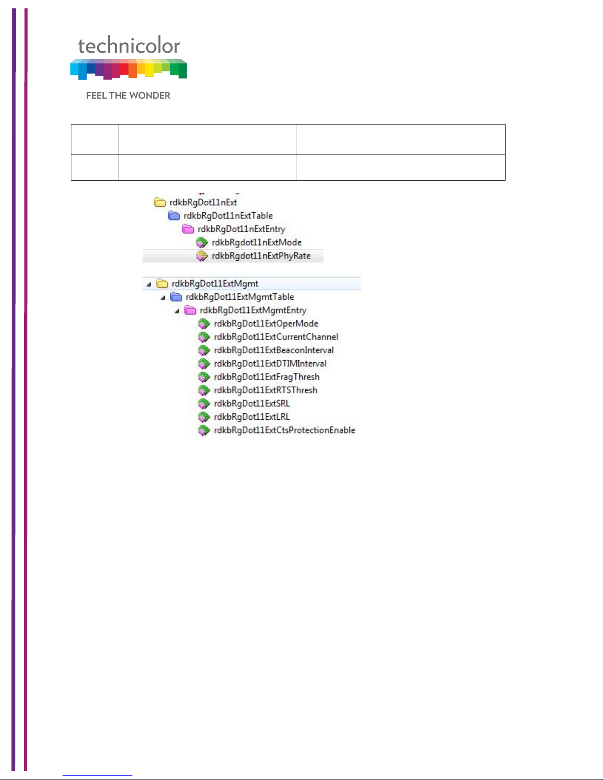
7.3.2 SNMP provisioning for Advanced Wireless Setting
S. No.
MIBs
Description
1
rdkbRgdot11nExtPhyRate
rdkbRgdot11nExtPhyRatesets the
transmission rate.
2
rdkbRgdot11ExtCtsProtectionE
nable
rdkbRgdot11ExtCtsProtectionEnable
sets the CTS protection mode.
3
rdkbRgDot11ExtBeaconInterval
rdkbRgDot11ExtBeaconIntervalsets
the beacon interval.
4
rdkbRgDot11ExtDTIMInterval
rdkbRgDot11ExtDTIMIntervalsets the
DTIM interval.
Page 67
3/6/2018 Proprietary and Confidential - Technicolor 61
5
rdkbRgDot11ExtFragThresh
rdkbRgDot11ExtFragThreshsets
the fragmentation threshold.
6
rdkbRgDot11ExtWmm
rdkbRgDot11ExtWmm enables or
disables WMM.
7.4 Guest Network
This page displays Guest networks configuration. The user can configure Guest networks
for both 2.4GHz and 5GHz radios. Users can set their own guest network SSID, Passphrase
and DHCP address as well. Up to 7 guest SSIDs can be configured per radio.
Wireless Tab / Guest Network
Click on the Wireless tab then click on the Guest Networks tab. The page displays Guest
Networks and Guest LAN Settings.
Guest Networks view shows names of all the guest networks configured, MAC address,
Enable/Disable status and Broadcast SSID status for each one of them. The following figure
provides that view:
Page 68

3/6/2018 Proprietary and Confidential - Technicolor 62
Figure 7.8
The Guest LAN view provides the configuration of a guest network. The network name,
security mode, number of guests allowed in the network, IP address and DHCP
configurations.
User can select the specific network name to view the configuration of that network. The
figure below provides Guest LAN Settings view:
Page 69

3/6/2018 Proprietary and Confidential - Technicolor 63
Figure 7.9
7.4.1 User provisioning for Guest Network
The user can configure the properties of a guest network (Network Name, SSID Broadcast
status and enabling and disabling of the guest network) and the LAN configuration for each
of the guest networks.
7.4.1.1 Guest Network
Wireless Interface:
This tab allows the user to select the wireless interface of the guest network (2.4GHz or
5GHz).
Page 70

3/6/2018 Proprietary and Confidential - Technicolor 64
Figure 7.10
Network Name:
The Network Name shown here is the Guest Network name and different from the Network
Name on the previous “Radio” tab. The user can change the default “SSID3- 2.4” to the
desired value.
MAC Address:
The MAC address of the wireless interface is displayed in this field.
SSID Broadcast:
User can enable or disable this feature by the toggle button provided under SSID Broadcast;
this is similar to Network Name “Hide” feature on the Radio tab in that it prevents the SSID
from being broadcast.
Enable:
The user can enable or disable the Guest SSID by this toggle button.
7.4.1.2 Guest LAN Settings
Network Name:
SSIDs corresponding to the Wireless Interface selection are shown here.
Security Mode:
Please refer to 7.2.1 Security tab; settings are same. The user can select Security Mode,
Encryption and the Network Password.
Page 71

3/6/2018 Proprietary and Confidential - Technicolor 65
DHCP Server:
When enabled, the CGA4131 automatically assigns IP addresses. If disabled, parameters
can be configured manually.
Figure 7.11
Note: Do not forget to hit the Save button after all changes are made.
7.4.2 SNMP provisioning for Guest Network
The following MIBs are used for provisioning the Guest Network:
S. No.
MIBs
Description
1
rdkbRgDot11BssId
Returns the BSSID
2
rdkbRgDot11BssEnable
Controls the BSS state.
3
rdkbRgDot11BssSsid
Controls and reflects the service set
identifier.
4
rdkbRgDot11BssSecurityMode
Security for BSS.
Page 72

3/6/2018 Proprietary and Confidential - Technicolor 66
5
rdkbRgDot11BssClosedNetwork
Controls whether the device will
operate in closed network mode.
6
rdkbRgDot11BssAccessMode
Controls what stations will be given
access to the device.
7
rdkbRgDot11BssMaxNumSta
This object defines the maximum
number of STAs that can connect to
this SSID. Note that the maximum
number of STA across all SSIDs in the
AP is 128. Default value is 128 for all
SSIDs.
8
rdkbRgDot11BssCountStaAsCpe
This setting is used to control
counting STAs in Max-Count of
CPEs.
9
rdkbRgDot11BssUserStatus
Provides the BSS Id Web UI or
Wireless ON/OFF (if exist) status that
is set by the user.
10
rdkbRgDot11BssHotSpot
Determines/Sets whether this BSS is a
Hotspot BSS. This allows the MSO to
specify which BSS is configured for
Hotspot Operation.
11
rdkbRgDot11BssApIsolation
AP Isolation (Access Point
Isolation) allows isolating traffic
between CPEs on the same Wi-Fi
SSID.
The following MIBS determine how many user controlled and admin controlled Guest Wi-Fi
can be configured and displayed in GUI:
S. No.
MIBs
Description
1
rdkbRgDot11ExtMbssUserControl
Sets the number of user controlled
guest networks via Web UI
2
rdkbRgDot11ExtMbssUseNonvol
Allows to save additional BSS
parameters to non-vol if set to
TRUE
3
rdkbRgDot11ExtMbssAdminControl
Sets the number of admin controlled
guest networks via Web UI
Page 73

3/6/2018 Proprietary and Confidential - Technicolor 67
Page 74

3/6/2018 Proprietary and Confidential - Technicolor 68
7.5 MAC Control
Wireless access can be filtered by using the MAC addresses of the clients that are connected
to Wi-Fi.
Wireless Tab / MAC Control
Click on the Wireless tab then click on MAC Control tab. The page displays MAC Control
setup information. Here the user can set and display Network Name, Wi-Fi MAC Control,
Access Restriction, MAC Control List (Device Name, MAC Address, Delete), Auto Learned
Device (Device Name, MAC Address, IP Address, Status, Add).
Figure 7.12
Page 75

3/6/2018 Proprietary and Confidential - Technicolor 69
7.5.1 User provisioning for MAC Control
7.5.1.1 Network Name
Network name can be selected from the Drop down menu.
7.5.1.2 Wi-Fi MAC Control
Wi-Fi MAC Control can be enabled by the selection Wi-Fi MAC Control option.
7.5.1.3 Access Restrictions
Select the Deny or Allow button to block or permit the MAC addresses listed to access the
wireless network.
7.5.1.4 MAC Control List
The gateway can manage the network access of select client devices if they are entered in
this list using that device’s MAC address.
Click the Add button to add to the list. Add the required details in the entries and click Save
to add them into the control list.
7.5.1.5 Auto Learned Device
Auto learned devices are the Wi-Fi clients that are discovered by the gateway. The user can
add them to the MAC control list by selecting the add option in the screen.
7.5.2 SNMP provisioning for MAC Control
rdkbRgDot11BssAccessModeenables/disables MAC Filter and specifies the access
restriction mode.
S. No.
MIBs
Description
1
rdkbRgDot11BssAccessMode
Controls what stations will be given access
to the device. If set to allowAny (0), then
any station will be allowed to connect. If
set to allowList (1), then only stations
whose MAC address appears in the
rdkbRgDot11AccessMacTable will be
allowed to connect. The value for primary
BSS is stored in non-vol. The default value
for other BSSs is 0
Page 76

3/6/2018 Proprietary and Confidential - Technicolor 70
7.6 WPS
Wi-Fi Protected Setup (previously called Wi-Fi Simple Config) is an optional certification
program developed by the Wi-Fi Alliance designed to ease set up of security-enabled Wi-Fi
networks at home and small office environments. Wi-Fi Protected Setup supports simple
methods (by either pushing a button or entering a PIN into a wizard-type application) to pair
a client and gateway.
The main aim of this protocol is to make gateway and client device connectivity easy for
users who have very little knowledge of setting Wi-Fi security parameters, are tired of
entering existing long passphrases and browser-less gaming clients where there is no option
to enter a passphrase.
Wi-Fi Protected Setup (WPS) facilities users to easily connect to the wireless network by
simply pushing a button or entering a PIN code. WPS permits home users to easily connect
to a secure network without any complex configuration and eliminates the need to remember
or store their security information in an unsafe way.
There are 3 ways to use WPS:
1. Push-Button Configuration (PBC) method:
In this, the user has to push a button, either an actual or a virtual one, on both the access
point and the new wireless client device. Support of this mode is mandatory for access points
and optional for connecting devices. The Wi-Fi Direct specification supersedes this
requirement by stating that all devices must support the push button.
The Technicolor CGA4131 TCH2-GA-TBRprovides two WPS PBC buttons;
(1) HW button on the front panel
(2) SW button on the WebUI, as shown right.
Pressing either HW or SW PBC button will flash the WPS LED and perform the WPS PBC
operation. Then, press the SW PBC button in the client device software (or a HW button in
some devices). These buttons must be pushed within 60 seconds of each other.
Page 77

3/6/2018 Proprietary and Confidential - Technicolor 71
2. Personal Identification Number (PIN) method:
This method is the mandatory baseline mode and every device must support it. The Wi-Fi
Direct specification supersedes this requirement by stating that all devices with a keypad or
display must support the PIN method
Enter the client device’s PIN number here and click the Register button. If the WPS LED on
the front panel flashes, press the start button in the client device software. If the client device
software asks the target SSID, enter the current SSID shown on the WebUI. If a wrong PIN
number was input, the client device will not be connected.
3. External Registrar (ER) method:
If the client device software supports the ER method, enter the gateway’s SSID and PIN
number in the client device software, and then press the start button. In this method, no
action is required, and the WPS LED on the front panel will start to blink automatically. When
the gateway detects an attempt with an invalid PIN, it doubles the lockout time. If it detects
10 attempted with invalid PIN since booting, the ER method will be disabled permanently.
7.6.1 User provisioning for WPS
Wireless Tab / WPS
Click on the Wireless tab and then click on the WPS control tab. The page displays WPS
setup information. Here user can set and display WPS parameters including the Access
Point PIN and Connection Method (Push Button/ PIN Number).
Page 78

3/6/2018 Proprietary and Confidential - Technicolor 72
Figure 7.13
7.7 QoS
By default, networks operate on a best-effort delivery basis, which means that all traffic has
equal priority and an equal chance of being delivered in a timely manner. When congestion
occurs, all traffic has an equal chance of being dropped. Implementing QoS in wireless LAN
makes network performance more predictable and bandwidth utilization more effective.
Note: When QoS is enabled, the device uses Wi-Fi Multimedia (WMM) mode by default.
Wireless Tab / QoS
Click on the Wireless tab then click on the QOS tab. The page displays QoS setup
information. Here, the user can set and display SSID Index, Radio Band, Network Name,
Wi-Fi Multimedia (WMM), WMM Power Save, Preset QoS Level (Low, Medium and
High),Index, IcAifsn, IcEcwMin,IcEcwMax,IcTxOp, IcAckPolicy.
Page 79

3/6/2018 Proprietary and Confidential - Technicolor 73
Figure 7.14
7.7.1 User provisioning for QOS
SSID Index:
The user can select any number from the drop down list, where 1 represents 2.4GHz and 2
represents 5GHz.Other numbers will be assigned to the Guest SSIDs, if applicable.
Radio Band:
This tab only displays which Wireless band is selected, dependent on the selection of SSID
Index.
Network Name:
The network name of the selected SSID index is shown.
Wi- Fi Multimedia and WMM Power Save:
Please refer to section 7.3.1for definitions.
Note: It’s recommended not to change anything under this tab; any incorrect settings can
lead to degradation in wireless network performance.
Page 80

3/6/2018 Proprietary and Confidential - Technicolor 74
7.7.2 SNMP provisioning for QoS
S. No.
MIBs
Description
1
rdkbRgDot11ExtWmm
rdkbRgDot11ExtWmmenables or
disables WMM.
2
rdkbRgDot11ExtWmmNoAck
rdkbRgDot11ExtWmmNoAckenables
or disables the no acknowledgement
feature for WMM.
7.8 Hotspot
CGA4131 supports Wi-Fi hotspot functionality where secondary SSIDs can be configured
as public access points.
CGA4131 must establish a connection to a remote endpoint over GRE. Traffic is routed to
the GRE endpoint over routes established in the route table. When a data packet is received
by the GRE endpoint, it is de-encapsulated and routed to its destination address.
Wireless Tab / Hotspot
Figure 7.15
Page 81

3/6/2018 Proprietary and Confidential - Technicolor 75
Figure 7.16
Page 82

3/6/2018 Proprietary and Confidential - Technicolor 76
Figure 7.17
7.8.1 Enabling GRE hotspot with cable modem configuration file
CM Config file snippet for L2OGRE tunnel establishment
SnmpMibObject rdkbRgL2ogrePriRemoteAddressType.0 Integer 1; /* ipv4 */
SnmpMibObject rdkbRgL2ogrePriRemoteAddress.0 HexString 0xae44ea7e;
SnmpMibObject rdkbRgL2ogreKeepAliveMode.0 Integer 1; /* disabled */
SnmpMibObject rdkbRgL2ogreSourceIf.7 Integer 7; /* wifi1-6 */
SnmpMibObject rdkbRgL2ogreSourceIf.15 Integer 15; /* wifi2-6 */
SnmpMibObject rdkbRgL2ogreSourceIfEnabled.7 Integer 1; /* true */
SnmpMibObject rdkbRgL2ogreSourceIfEnabled.15 Integer 1; /* true */
SnmpMibObject rdkbRgL2ogreSourceIfVlanTag.7 Integer 300;
SnmpMibObject rdkbRgL2ogreSourceIfVlanTag.15 Integer 300;
SnmpMibObject rdkbRgL2ogreSourceIfMplsHeader.7 Integer 0;
SnmpMibObject rdkbRgL2ogreSourceIfMplsHeader.15 Integer 0;
SnmpMibObject rdkbRgL2ogreSourceIfRowStatus.7 Integer 1; /* active */
SnmpMibObject rdkbRgL2ogreSourceIfRowStatus.15 Integer 1; /* active */
SnmpMibObject rdkbRgWifiHotspotEnabled.0 Integer 1; /* true */
Page 83

3/6/2018 Proprietary and Confidential - Technicolor 77
SnmpMibObject rdkbRgL2ogreEnabled.0 Integer 1; /* true */
CM Config file snippet for Hotspot SSID configuration
SnmpMibObject rdkbRgDot11BssEnable.10008 Integer 1; /* enable */
SnmpMibObject rdkbRgDot11BssEnable.10108 Integer 1; /* enable */
SnmpMibObject rdkbRgDot11BssSsid.10008 String "TCH WiFi-DEV”;
SnmpMibObject rdkbRgDot11BssSsid.10108 String "YCH WiFi-DEV”;
SnmpMibObject rdkbRgDot11BssSecurityMode.10008 Integer 0; /* disabled */
SnmpMibObject rdkbRgDot11BssSecurityMode.10108 Integer 0; /* disabled */
SnmpMibObject rdkbRgDot11BssHotSpot.10008 Integer 1; /* true */
SnmpMibObject rdkbRgDot11BssHotSpot.10108 Integer 1; /* true */
SnmpMibObject rdkbRgDot11BssEntry.16.10008 Integer 1
SnmpMibObject rdkbRgDot11BssEntry.16.10108 Integer 1;
After the unit comes online with Opt-in hotspot configuration, client devices can be
connected to the hotspot SSID and can access the internet. Clients will be assigned IP
address by the tunnel endpoint. Separate service flow is created for hotspot traffic to isolate
traffic from private local network.
7.8.2 SNMP provisioning for Hotspot
Hotspot feature is configured using the following MIB elements. An entry defining the Wi-Fi
hotspot connected clients:
This table provides statistical information of GRE tunnel:
Page 84

3/6/2018 Proprietary and Confidential - Technicolor 78
8 Security
Security settings within the CGA4131 TCH2-GA-TBR’s page allow blocking or selectively
allowing different types of data through the router from the WAN to the LAN. Additionally,
the settings allow the device’s firewall to be enabled or disabled. The following security
settings are provided:
• Java Applets, Cookies, ActiveX controls, Popup Windows, and Proxies can be
blocked using this page. Firewall Protection turns on the Stateful Packet Inspection
(SPI) firewall features.
• Block Fragmented IP packets prevents all fragmented IP packets from passing
through the firewall.
• Port Scan Detection detects and blocks port scan activity originating on both the LAN
and WAN.
• IP Flood Detection detects and blocks packet floods originating on both the LAN and
WAN.
Click the Apply button to activate any of the checkbox items. These settings can be activated
without a device reboot.
8.1 Firewall
Security Tab / Firewall
Use the Firewall screen to configure a firewall that can filter out various types of unwanted
traffic on the gateway local network.
Procedure
Click on the Security tab, and then click on Firewall tab. The page displays Firewall setup
information. Here user can set and display the following:
IPv4 Firewall: Firewall Security Level, LAN – to – WAN, WAN – to – LAN
IPv6 Firewall: IPv6 Firewall Security Level, LAN – to – WAN, WAN – to – LAN
Advanced Settings: IPSec Passthrough, PPTP Passthrough, Block Fragmented IP
Packets, IP Flood Detection.
Page 85

3/6/2018 Proprietary and Confidential - Technicolor 79
Figure 8.1
The following table explains the traffic restrictions while setting the firewall level to various
levels – High, Medium, Low and Off.
Firewall
level
Restrictions on inbound
traffic
Restrictions on outbound
traffic
Remarks
High
All unsolicited inbound
traffic is blocked, and
Intrusion Detection is
enabled.
All traffic except the
following are restricted:
• HTTP and HTTPS (TCP
ports 80, 443)
• DNS (TCP/UDP port 53)
• NTP (UDP ports 119, 123)
• Email (TCP ports 25, 110,
143, 465, 587, 993, 995)
• VPN (GRE, UDP port 500,
TCP port 1723)
• iTunes (TCP port 3689)
Both inbound and
outbound traffic are
restricted
Medium
Inbound traffic is blocked for
the following services:
No restrictions - Outbound
connections are allowed by
the firewall regardless of the
Page 86

3/6/2018 Proprietary and Confidential - Technicolor 80
• IDENT protocol (TCP
port 113)
• ICMP request
• Peer-to-Peer
applications
• Kazaa (TCP/UDP port
1214)
• BitTorrent (TCP ports
6881-6999)
• Gnutella (TCP/UDP port
6346)
• Vuze (TCP ports 49152-
65534)
Intrusion Detection is
enabled in the Medium
operating level. All other
inbound traffic is allowed by
the firewall. Please note
that unsolicited inbound
traffic will not be forwarded
to devices on home
network unless they match
a port forwarding /
triggering rule, or a DMZ
host has been configured.
service or port(s) being
used for the connection.
Low
Inbound traffic is blocked for
the following services:
• IDENT protocol (TCP
port 113)
Intrusion Detection is
enabled in the Low
operating level. All other
inbound traffic is allowed by
the firewall. Please note
that unsolicited inbound
traffic will not be forwarded
to devices on home
network unless they match
a port forwarding /
triggering rule, or a DMZ
host has been configured.
No restrictions - outbound
connections are allowed by
the firewall regardless of the
service or port(s) being
used for the connection.
Off
No restrictions. Can be
enabled through port
forward/ port trigger/DMZ
rule
No restrictions
Firewall configuration is
disabled.
Page 87

3/6/2018 Proprietary and Confidential - Technicolor 81
8.1.1 User provisioning for Firewall
The following screens provide a view on the various configurations for IPv4 and IPv6
firewalls supported:
Figure 8.2
Figure 8.3
Page 88

3/6/2018 Proprietary and Confidential - Technicolor 82
Figure 8.4
Similar configurations can be done for the IPv6 firewalls in the system. By default, the firewall
configuration is set to “Off”.
8.1.2 SNMP provisioning for Firewall
SNMP provisioning is done by the following MIBs for Firewall Basic settings
S. No.
MIBs
Description
1
rdkbRgFirewallProtection
Controls the firewall. This parameter is stored in nonvol and is enabled after factory reset. Options are
Disable / Low, Medium, High and Custom.
Page 89

3/6/2018 Proprietary and Confidential - Technicolor 83
8.2 IP Filter
IP filter functionality is used to block internet access for the clients with the IP address range
selected in the Web UI.
8.2.1 User provisioning for IP Filter
To activate the IP address filter, provide the IP address range, click Enable and then click
Save Settings.
Security Tab / IP Filter
This page displays IP Filter Table information. Here, user can set and display Start Address,
End Address, Enable and Delete for IP Filtering.
Figure 8.5
8.3 Device Filter
The Device Filter page is used to allow or block devices connecting to the router, for both
LAN and Wi-Fi clients. The devices are allowed or blocked with respect to their MAC
Page 90

3/6/2018 Proprietary and Confidential - Technicolor 84
address, which is added in the allowed devices list in this page. User can add devices
through auto learnt devices under the device list or add a device manually under the Allowed
Devices list.
Security Tab / Device Filter
Click on the Security tab then click on Device Filter tab. The page displays following Device
Filter setup information:
• Device Filter Status - (Enabled / Disabled)
• Access Type - (Allow All / Block All)
• Blocked Devices List - (Computer Name, MAC Address, When Block, and Delete)
• Devices List–List of auto learnt devices (Computer Name, MAC Address, Status, and
Operation)
Figure 8.6
8.3.1 User provisioning of Device Filter
User provisioning involves enabling or disabling the feature (using Device Filter option),
selecting the filter type (Allow all or Deny All) and adding the devices into the Blocked List.
Enable Device Filter
Device Filter can be enabled with Access type either Block All devices or Allow All devices
status. Filter can be enabled by clicking on the corresponding button.
Page 91

3/6/2018 Proprietary and Confidential - Technicolor 85
Block All
When Block All option is selected, all devices except in the Allowed Devices would be
blocked for internet access.
Allow All
When Allow All option is selected, all devices except in the Blocked Devices would be
allowed for internet access.
Options for time of the day filters – When Block
When the user configures the “When Block” option to select the day of the week and the
time of the day, the device filter would be activated only for the selected time of the day
option.
8.3.2 SNMP provisioning for Device Filter
SNMP provisioning is done by the following MIBs for Device Filter:
S. No.
MIBs
Description
1
rdkbRgFirewallMacFilterEna
ble
True = Enable the Mac address filtering feature.
False = disable. This Value is written to non-vol
and set to false after a factory reset.
2
rdkbRgFirewallMacFilterMod
e
Block (0) - Macs listed in the
rdkbRgFirewallMacFilterEntryTable will be
blocked.
Permit (1) - Macs listed in the
rdkbRgFirewallMacFilterEntryTable will be
permitted.
This value is written to non-vol and is set to
block (0) after a factory reset.
8.4 Access Control
The Access Control page is used to block websites based on their URL. User can add the
desired website under the Blocked sites and the added website will be blocked for both LAN
and WLAN devices, which are connected through the router.
Security Tab / Access Control
Click on the Security tab then click on Access Control tab.
Page 92

3/6/2018 Proprietary and Confidential - Technicolor 86
This page displays following Site Filter setup information which can be viewed and set by
user:
• Site Filter Status: (Enabled / Disabled)
• List of Blocked Sites: (with Content, Type, When, Delete information)
• Trusted Devices: List of devices auto leant in the gateway.(with Computer Name,
MAC Address, IP Address, Trusted information)
Figure 8.7
8.4.1 User provisioning for Access Control
User provisioning involves enabling or disabling the Access control feature using Site Filter
option.
Blocked Sites
The user needs to create the Blocked Sites by adding the URL details, type, and time of the
day for the filter to be enabled to the list. There is an option to delete the URLs from the
Blocked Sites list.
Trusted Devices
The user can override this feature for specific devices. They need to be added in the Trusted
Devices list with Trusted button enabled.
Page 93

3/6/2018 Proprietary and Confidential - Technicolor 87
8.4.2 SNMP provisioning for Access Control
The following MIBs configure the Access Control feature:
S. No.
MIBs
Description
1
rdkbRgFirewallUrlKeywordFi
lterEnable
True = Enable the URL Keyword filtering feature.
False = Disable.
2
rdkbRgFirewallUrlKeywordFi
lterRowStatus
The row status. A row can be destroyed. If the
row is not used, set to notInService
3
rdkbRgFirewallUrlKeywordFi
lterMethod
URLs or specific words according to Method set
4
rdkbRgFirewallUrlKeywordFi
lterMatch
URLs or specific words according to Method set
5
rdkbRgFirewallUrlKeywordFi
lterAlwaysBlock
If true (1), always be blocked, regardless of
startTime, endTime and blockDays. If false(2),
blocked at time set in startTime, endTime and
blockDays
6
rdkbRgFirewallUrlKeywordFi
lterBlockStartTime
24 Hour format HH:MM to set the start time to
block
7
rdkbRgFirewallUrlKeywordFi
lterBlockEndTime
24 Hour format HH:MM to set the end time to
block
8
rdkbRgFirewallUrlKeywordFi
lterBlockDays
BITMAP to indicate which days to block
8.5 Service Filter
The Service Filter page is used to block certain service requests coming from the LAN to
WAN devices connected through the router. User can block the desired service port range
by adding it to Blocked services
Security Tab / Service Filter
Click on Security tab then click on Service Filter tab. The page displays following Service
Filter setup information, which can be viewed and modified by user.
• Service Filter (Enable / Disable)
• Blocked Services - The specific traffic / service that are blocked using the Service
Filter. This could be protocols or port numbers - Services Name, TCP/UDP, Start
Port, End Port, Time (When), and Delete
• Trusted Devices–List of auto leaned devices in the LAN. Service filter can be enabled
or disabled for these devices by selecting the Trusted option.
Page 94

3/6/2018 Proprietary and Confidential - Technicolor 88
Figure 8.8
8.5.1 User provisioning for Service Filter
User can enable this feature by enabling the Service Filter option.
Blocked Services
The user needs to create the services list. This can be done by adding an entry and selecting
the protocol and port information. The user needs to configure the time of the day
configurations (option When) – the time when the filter should be enabled for the enabled
devices.
Trusted Devices
The user needs to enable or disable the feature for the specific devices – this can be done
by enabling the Trusted button in the Trusted Devices list. If the Trusted button is enabled,
the service filter is applied as per the service filter definitions (Protocol, Port Range and Time
of the day).
8.5.2 SNMP provisioning for Service Filter
The following MIBs configure the Service Filter feature:
Page 95

3/6/2018 Proprietary and Confidential - Technicolor 89
S. No.
MIBs
Description
1
rdkbRgFirewallPortFilterEna
ble
True = Enable the Port filtering feature.
False = Disable.
8.6 VPN Tunnel Settings
This feature is used in cases where the gateway acts as the VPN endpoint and the user
needs to make all the machines connected to the LAN side to be part of the enterprise
private network. This is mainly used in B2B (Business-2-Business) applications.
For the CGA4131 TCH2-GA-TBRto act as a VPN endpoint, configurations can be done from
the Security ->VPN page.
Enter the details of the local subnet and the remote subnet including the VPN gateway and
security parameters for IPSEC (Key Exchange Method, Encryption, Authentication, Pre-shared key. etc.). Obtain these details from the network administrator (of the enterprise
connecting to) before setting up the VPN tunnel.
Security Tab / VPN
Click on Security tab then click on VPN tab. The page displays VPN setup information. Here
the user can set and display VPN information.
Figure 8.9
The user can configure the VPN Tunnel details by clicking on ‘+’ symbol corresponding to
the VPN Tunnel option. The page will show the following information:
• Enable (Option to enable VPN),
• Tunnel Name (Name of the tunnel to be created between endpoints)
• Local Secure Group: - (IP Address, Subnet Mask)
• Remote Secure Group: - (IP Address, Subnet Mask)
• Remote Secure Gateway: - (IP Address)
• Key Management: - (Key Exchange Method, Encryption Algorithm, Authentication
Page 96

3/6/2018 Proprietary and Confidential - Technicolor 90
• Algorithm, Pre –Shared Key, Key Life Time)
Figure 8.10
Figure 8.11
Page 97

3/6/2018 Proprietary and Confidential - Technicolor 91
Figure 8.12
8.6.1 User provisioning for VPN
The following table explains the various parameters and possible configurations for each of
the parameters to edit/create a VPN entry:
VPN Tunnel
Select Tunnel Entry:
Select a tunnel to configure.
‘+” Button: Click this button to create a new tunnel.
‘X’ Button: Click this button to delete all settings for the selected
tunnel.
Enable
To Enable VPN Tunnel.
Tunnel Name:
Enter a name for this tunnel, such as London Office.
Local Secure Group
Select the local LAN user(s) that can use this VPN tunnel. This
may be a single IP address or sub-network. Note that the Local
Secure Group must match the remote gateway's Remote Secure
Group.
IP Address:
Enter the IP address on the local network.
Subnet Mask:
If the Subnet option is selected, enter the mask to determine the
IP Addresses on the local network.
Page 98

3/6/2018 Proprietary and Confidential - Technicolor 92
Remote Secure Group
Select the remote LAN user(s) behind the remote gateway who
can use this VPN tunnel. This may be a single IP address, a
sub-network, or any addresses. If Any is set, the gateway acts
as a responder and accepts requests from any remote user. Note
that the Remote Secure Group must match the remote gateway's
Local Secure Group.
IP Address:
Enter the IP address on the remote network.
Subnet Mask:
If the Subnet option is selected, enter the mask to determine the
IP addresses on the remote network.
Remote Secure
Gateway
Select the desired option, IP Address.
Key Management
Key Exchange Method:
The device supports both automatic and manual key
management. When automatic key management is selected,
Internet Key Exchange (IKE) protocols are used to negotiate key
material for Security Association (SA). If manual key management
is selected, no key negotiation is needed. Manual key
management is used in small static environments or for
troubleshooting purposes. Note that both sides must use the same
key management method.
Encryption Algorithm:
The Encryption method determines the length of the key used to
Encrypt/decrypt ESP packets. Note that both sides must use the
Same method.
Available Options are DES, 3DES, AES-128, AES-129, AES-256
Authentication Algorithm:
The Authentication method authenticates the Encapsulating
Security Payload (ESP) packets. Select MD5 or SHA. Note that
both sides (VPN Endpoints) must use the same method.
MD5: A one-way hashing algorithm that produces a 128--
bitdigests
SHA1: A one-way hashing algorithm that produces a 160bitdigests
Pre-Shared Key:
IKE uses the Pre-Shared Key to authenticate the remote IKE peer.
Both character and hexadecimal values are acceptable in this
field, e.g., My_@123 or 0x4d795f40313233. Note that both sides
must use the same Pre-Shared Key.
Key Lifetime:
This field specifies the lifetime of the IKE generated key. If the time
Expires, a new key will be renegotiated automatically. The Key
Page 99

3/6/2018 Proprietary and Confidential - Technicolor 93
Lifetime may range from 300 to 100,000,000 seconds. The default
lifetime is 3600 seconds.
Enable: To Enable the Key Management.
Tunnel Name: This field specifies Tunnel Name.
The user needs to select the required values and options for the above parameters and
press Save button on the Web UI page to save them.
8.7 Email settings
Security Tab / Email Settings
Click on Security tab then click on Email settings tab. The page displays Email
settings information which can be viewed and modified by the user. The following information
will be displayed:
• Recipient Email
• Notification Types - (Firewall Breach, Access Control Breach, Alerts or Warnings,
Send Logs)
• Mail Server Configuration - (SMTP Server Address, Send Email Address, Username
and Password)
Page 100

3/6/2018 Proprietary and Confidential - Technicolor 94
Figure 8.13
8.7.1 User provisioning for Email
The notification types needed is enabled using the options in the screen. By default, all
notifications are disabled.
The email notifications would be sent to the mail server configured - SMTP server address,
email address, user name and password should to be configured.
8.7.2 SNMP provisioning for Email
The following MIBs implement this feature:
S. No.
MIBs
Description
1
rdkbRgFirewallReportEmailEnable
Enables sending logs via email.
Email is sent when an event
happens
 Loading...