

Page 1

TECHNICAL PRO INC
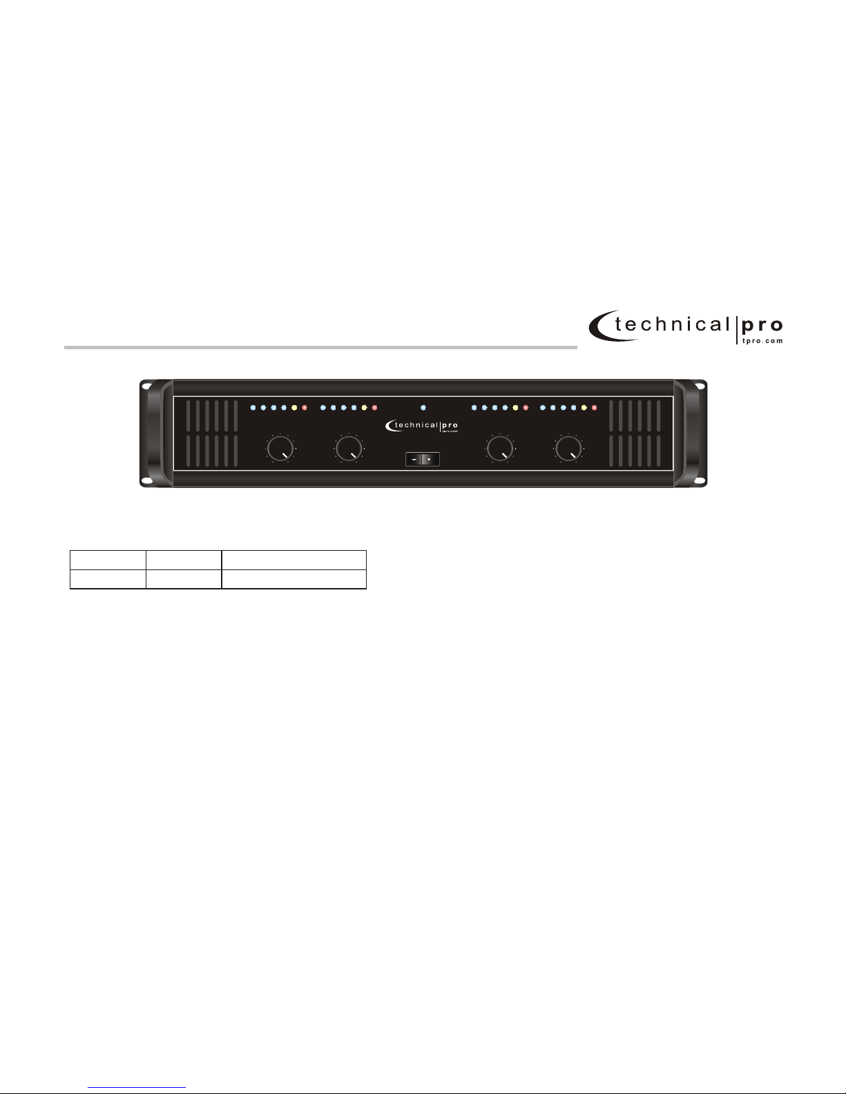
L SERIES
4 WAY PROFESSIONAL AMPLIFIER
WWW.TPRO.COM
Page 2

Table of Contents
page2
1 Welcome
....................................................................................
3
2 Setup
........................................................................................... 4
4
2.1 Unpack Your Amplifier
.................................................................
3 Operation
9
.....................................................................................
4
2.2 Install Your Amplifier
................................................................
4
2.3 Ensure Proper Cooling
...............................................................
5
2.4 Choose Input Wire and Connectors
.....................................
6
2.5 Choose Output Wire and Connectors
....................................
7
2.6 Wiring Your System
....................................................................
7
2.6.1 Stereo Mode
....................................................................
7
2.6.2 How to Parallel the Inputs
..........................................
8
2.6.3 Bridge-Mono Mode
........................................................
4 Warranty
10
....................................................................................
L - SERIES 4 Way Professional Amplifier
Page 3
Page3
1 Welcome
Technical Pro’s L- 4 way
s.
equipment
L-
so they can
be used correctly.
Series amplifiers provide
professional audio amplification for a wide range
of application These amplifiers feature front panel
controls for easy setup and use.
Modern power amplifiers are sophisticated pieces of
capable of producingextremely high power
levels.
In addition, Series amplifiers include a number of
features which require some explanation
Please take the time to study this manual sothat you
can obtain the best possible servicefrom your amplifier.
ON OFF
L4Z-4001L4Z-4001
POWER
MIN MAX MIN MAX
CH1 Ch2
CLIP +12 +6 0 -6 -12 CLIP +12 +6 0 -6 -12
MIN MAX MIN MAX
Ch3 Ch4
CLIP+12+60-6-12 CLIP+12+60-6-12
L - SERIES 4 Way Professional Amplifier
Dimensions
19”w x 3.5”h x 18”d
4000 Watts
Peak Power
ITEM
L4Z-4001
Page 4

2 Setup
Page4
2.1 Unpack Your Amplifier
Please unpack and inspect your amplifier for
any damage that may have occurred during
transit. If damage is found, notify the transportation company immediately. Only you can initiate a claim for shipping damage.
We also recommend that you save all packing
materials so you will have them if you ever
need to transport the unit. Never ship the
unit without the factory packing material.
You will need:
*Input wiring cables (not supplied)
*Output wiring cables (not supplied)
Rack and rack-mounting hardware for mounting
amplifier .
WARNING: Before you start to set up
your amplifier, make sure you read and
observe the Important Safety Instructions
found at the beginning of this manual.
!
!
2.2 Install Your Amplifier
CAUTION: Before you begin, make sure
your amplifier is disconnected from the
power source, with the power switch in
the off position and all level controls
turned completely down
(counterclockwise).
Use a standard 19-inch (482.6 mm) equipment
rack. See Figure 2.2 for amplifier dimensions.
You may also stack amps without using a
cabinet.
NOTE: When transporting, amplifiers should
be supported at both front and back.
2.3 Ensure Proper Cooling
When using an equipment rack, mount units
directly on top of each other. Close any open
spaces in rack with blank panels. DO NOT
block front or rear air vents. Be sure that cooler
air can flow through the rack either from the
front of back of the rack.
Figure 2.2 L-Series Dimensions
19”
3.5”
ON OFF
L4Z-4001L4Z-4001
POWER
MIN MAX MIN MAX
CH1 Ch2
CLIP +12 +6 0 -6 -12 CLIP +12 +6 0 -6 -12
MIN MAX MIN MAX
Ch3 Ch4
CLIP+12+60-6-12 CLIP+12+60-6-12
L - SERIES 4 Way Professional Amplifier
Page 5

Page5
2 Setup
Figure 2.4.1 Balanced Input
Connector wiring
2.4 Choose Input Wire
and Connectors
You have two choices of input connectors:
1/4-inch (6.35-mm) phone, 3-pin XLR.
You can also use either balanced or
unbalanced wiring.
Figure 2.4.1 shows balanced connector pin
assignments for XLR and phone. Figure 2.4.2
shows unbalanced connector pin assignments
for XLR and phone.
Both channels should be wired
using a common center terminal for ground
connection.
NOTE: Custom wiring should only be
performed by qualified personnel.
!
Figure 2.4.2 Unbalanced Input
Connector wiring
L - SERIES 4 Way Professional Amplifier
Page 6

Page6
2 Setup
2.5 Choose Output Wire and Connectors
Technical Pro recommends using pre-built or professionally wired, high-quality, two- or fourconductor, heavy gauge speaker wires. Figure 2.5.1 shows how a user would connect the LSeries amplifier to a speaker using the Speakon™ connector.
Figure 2.5.2 shows another option users have when connecting the L-Series amplifier to a speaker.
Using banana plugs, spade plugs or simply bare wires, a user can connect two speakers to the amplifier.
Using banana plugs, spade plugs or bare speaker wires, a user can connect up to four speakers to
the amplifier. When connecting speaker wires to the banana binding post, be sure that you follow the
instructions very carefully. These connections will change depending on whether the unit is being operated
in Stereo or Bridged mode. In Stereo mode the banana plugs should be connected vertically in the CH.1
jacks (one wire in the positive and one in the negative jack). The same can be done for channels 2,3 and 4
depending on the number of inputs. In Bridged mode CH.1 and Ch.2 are combined and CH.3 and CH.4 can be
combined. If the CH.1 and CH.2 are Bridged, than the banana plug should be connected horizontally, along
the positive jacks of CH.1 and CH.2. If the CH.3 and CH.3 are Bridged, than the banana plug should be
connected horizontally, along the positive jacks of CH.3 and CH.4.
Using the guidelines below, select the appropriate size of speaker
wires based on the distance from amplifier to speaker.
Distance Wire Size
up to 25 ft. 16 gauge
26-40 ft. 14 gauge
41-60 ft. 12 gauge
61-100 ft. 10 gauge
101-150 ft. 8 gauge
151-250 ft. 6 gauge
CAUTION: Never use unshielded cable for output wiring.
Figure 2.5.1 ConnectorSpeakon™
Figure 2.5.2 Banana Plugs
L - SERIES 4 Way Professional Amplifier
Page 7

Ch1
-BRIDGE+
MONO
-BRIDGE+
MONO
Ch2 Ch3 Ch4
OUTPUT
110/220V
220/240V
50-60Hz
AC INPUT
L4Z-4001
INPUT
LIFT
GROUND
STEREO
BRIDGE
MONO
CH1/2
STEREO
BRIDGE
MONO
CH3/4
Page7
2 Setup
2.6 Wire Your System
2.6.1 Stereo Mode
Make sure the amplifier is turned off and the level controls
are turned down before you wire the system. Make sure the
stereo/bridge switch is set to stereo.
Typical input and output wiring is shown in Figure 2.6.1.
INPUTS: Connect the input wiring for each desired channel
using either the RCA or 1/4" jacks. Never used both the RCA
and 1/4" jacks simultaneously on a single channel.
OUTPUTS: Maintain proper polarity (+/-) on
output connectors.
In Stereo mode the banana plugs should be connected
vertically in the CH.1 jacks (one wire in the positive and
one in the negative jack). Be sure to maintain the positive
/negative polarity when connecting your amplifier to the
speaker. Positive terminal on the amplifier should be
connected to a positive terminal on the speaker. The
same should be done for the negative terminals.
2.6.2 How to Parallel the Inputs
There are two ways to feed the same signal to
each amplifier channel:
1. Buy a "Y" cable. Plug the female end into your
signal cable, and plug the split male ends into
both amplifier inputs.
2. Feed your signal to the Channel-1 input screw
terminals. Using a mic cable or phone-to-phone
cable, connect Channel-1 combo jack to Channel2 combo jack.
See the next page for Bridge-Mono wiring.
Ch3
Ch1
STEREOSTEREO
BRIDGEBRIDGE
MONOMONO
Figure 2.6 .1 Typical System Wiring, Stereo Mode
MIXER SPEAKER
Ch2 Ch4
Ch1 Ch2 Ch3 Ch4
L - SERIES 4 Way Professional Amplifier
Page 8

Ch1
-BRIDGE+
MONO
-BRIDGE+
MONO
Ch2 Ch3 Ch4
OUTPUT
110/220V
220/240V
50-60Hz
AC INPUT
L4Z-4001
INPUT
LIFT
GROUND
STEREO
BRIDGE
MONO
CH1/2
STEREO
BRIDGE
MONO
CH3/4
Ch1
STEREOSTEREO
BRIDGEBRIDGE
MONOMONO
MIXER SPEAKER
Ch3
Ch1 Ch3
Page8
2 Setup
2.6.3 Bridge-Mono Mode
Make sure the amplifier is turned off and the
level controls are turned down before you
wire the system. Make sure the stereo/bridge
switch is set to bridge.
Typical input and output wiring is shown in
Figure 2.6.3.
INPUTS: Connect input wiring to CH.1 and
CH.3. Never used both the RCA and 1/4" jacks
simultaneously on a single channel.
OUTPUTS: When operating the amplifier in
Bridge mode, only the Banana jacks can be
used. In Bridged mode CH.1 and Ch.2 are
combined and CH.3 and CH.4 can be combined.
If the CH.1 and CH.2 are Bridged, than the
banana plug should be connected horizontally,
along the positive jacks of CH.1 and CH.2.
If the CH.3 and CH.4 are Bridged, than the
banana plug should be connected horizontally,
along the positive jacks of CH.3 and CH.4. Refer
to Section 2.5 for output connector pin assi-
gnments. Make sure the Mode switch is set
to the "Bridge Mono" position when operating in Bridge-Mono mode.
NOTE: Turn down the Channel 2,4 level
control when operating the channel pair
in Bridge-Mono mode, as the Channel 1,3
level control works both channels.
!
Figure 2.6 .3 Typical System Wiring, Bridge-Mono Mode
L - SERIES 4 Way Professional Amplifier
Page 9

Ch1
-BRIDGE+
MONO
-BRIDGE+
MONO
Ch2 Ch3 Ch4
OUTPUT
110/220V
220/240V
50-60Hz
AC INPUT
L4Z-4001
Ch1
Ch2
Ch3Ch4
INPUT
LIFT
GROUND
STEREO
BRIDGE
MONO
CH1/2
STEREO
BRIDGE
MONO
CH3/4
L4Z-4001L4Z-4001
POWER
MIN MAX MIN MAX
CH1 Ch2
CLIP+12+60-6-12
MIN MAX MIN MAX
Ch3 Ch4
CLIP+12+60-6-12 CLIP+12+60-6-12
L - SERIES 4 Way Professional Amplifier
Page9
3 Operation
Ch1 Level Control
Speakon™ Outputs
Banana Post
Outputs
AC Power
Cord Connector
Stereo/BridgeMono Switch
Lift / Ground
Switch
CLIP+12+60-6-12
Ch1 Clip
Indicator
Ch1 Level
Indicator
Ch2 Clip
Indicator
Ch2 Level
Indicator
Ch3 Clip
Indicator
Ch3 Level
Indicator
Ch4 Clip
Indicator
Ch4 Level
Indicator
Power
Indicator
Power Switch
Ch2 Level Control Ch3 Level Control Ch4 Level Control
ONOFF
1/4” Input
RCA InputCooling fan
Power select
Page 10

LIMITED WARRANTY AND SERVICE
Technical Pro warrantees this product to be free from defective materials or factory workmanship and will replace or repair this unit or
any part thereof, except batteries, if if proves to be defective in normal use or service within 90 days from date of original purchase at our
discretion. The limited warranty is conditioned upon proper use of this product by its owner. Items not covered under this limited warranty
include; (a) defects or damage from abuse, accident, misuse, modifications, neglect, tampering, unusual electrical or physical stress, or cosmetic
damage. (b) scuffs or scratches from normal use. (c) units with illegible serial numbers. (d) defects or damage due to improper adjustments,
installations, maintenance service or testing. Technical Pro may repair or replace any defective unit or part at their own discretion. Technical Pro
may use new, repaired, or remanufactured parts to repair any unit. If Technical Pro determines that any items is not covered by this limited
warranty for any reason the purchaser will be responsible for parts, shipping and all labor charges associated with the repair or return of this unit.
To be eligible for service while your unit is under warranty you must return this product to Technical Pro’s Return Department. The unit must be
sent back in its original packaging materials and with an additional layer of packaging to ensure the safety of this unit during transit. Technical
Pro will not accept COD packages and no call tags will be issued for returned merchandise. A sales receipt, invoice or proof of purchase must be
sent with the unit along with the seller’s name and address in order to verify is the unit is still covered under Technical Pro’s limited warranty. A
brief explanation of the unit’s defect must also accompany the unit in addition to the owner ’s return shipping address. Be sure to include a check
or money order in the amount of $39.99 to cover the costs handling and return postage of this unit. This warranty gives you specific legal rights,
andyou may also have other rights, whichvaries from state to state. There are no other express warranties other than those stated herein. .
Technical Pro’s liability for any defective product is limited to the repair or replacement of the product at our option. Technical Pro shall
not be liable for: 1. Damage to other property caused by any defects in Technical Pro components. Damages based upon inconvenience,
loss of use of the product, loss of profit, injury or 2. Any other damages, whether incidental, consequential, indirect or otherwise. Some
states do not allow limitations on how long an implied warranty lasts and/or do not allow the exclusion or limitation of on incidental or
Send all warranty items to: Technical Pro Return Department, 140 58th Street, Suite 5G, Brooklyn NY 11220
Name:_______________________________ Address:________________________________________
Model:_____________ Serial Number:____________________ Purchase Date:__________________
Explanation of Defect:________________________________________________________________
_______________________________________________________________________________________
Exclusion on Damages:
 Loading...