

Page 1
EG
I
F
D
E
OPERATING INSTRUCTION ●ISTRUZIONI D’USO ●NOTICE D’UTILISATION
BEDIENUNGSANLEITUNGEN ●INSTRUCCIONES DE USO
INSTALLATION INSTRUCTION ●ISTRUZIONI D’INSTALLAZIONE ●NOTICE D’INSTALLATION
INSTALLATIONSANLEITUNGEN●INSTRUCCIONES DE INSTALACION
REVE 247C
37.4252.028.2 11/2009
Air conditioner •
Climatizzatore d’aria
• Climatiseur
Klimagerät
• Acondicionador de aire
COOL / DRY / FAN
COOL / DRY / HEAT / FAN
REVE 237R
Page 2

If you have problems or questions concerning your Air
Conditioner, you will need the following information. Model
and serial numbers are on the nameplate applied on the unit.
Model No.
Serial No.
Date of purchase
Dealer’s address
Phone number
The following symbols used in this manual, alert you to
potentially dangerous conditions to users, service personnel
or the appliance:
This symbol refers to a hazard or unsafe practice which
can result in severe personal injury or death.
This symbol refers to a hazard or unsafe practice which
can result in personal injury or product or property damage.
CONTENTS
1
PRODUCT INFORMATION
ALERT SYMBOLS
EG
WARNING
CAUTION
This air conditioner is equipped with cooling, drying and fan functions , cooling, drying, heating and fan
functions . Details on these functions are provided here following; refer on these descriptions
when using the air conditioner. This product is covered by patent nr. 261412 issued on the 8th of Genuary 2009.
NOTE
COOL/DRY/FAN
COOL /DRY/HEA T/F AN
DECLARATION OF CONFORMITY
This product is marked as it satisfies
Directives.
- Low voltage no. 2006/95/CE.
- Electromagnetic compatibily no.
89/336/CEE, 92/31/CEE and 93/68/CEE.
This declaration will become void in case of
misusage and/or non observance though
partial of Manufacturer’s installation and/or
operating instructions.
COOLING
OUTDOOR TEMPERATURE 43°C D.B.
ROOM TEMPERATURE 32°C D.B./23°C W.B.
OUTDOOR TEMPERATURE 19°C D.B.
ROOM TEMPERATURE 19°C D.B./14°C W.B.
OPERATING LIMITS
HEATING
OUTDOOR TEMPERATURE 24°C D.B./18°C W.B.
ROOM TEMPERATURE 27°C D.B.
OUTDOOR TEMPERATURE -8°C D.B./-9°C W.B.
ROOM TEMPERATURE -
OUTDOOR TEMPERATURE 43°C B.S.
ROOM TEMPERATURE 32°C B.S. / 80% R.H.
OUTDOOR TEMPERATURE 16°C B.S.
ROOM TEMPERATURE 16°C B.S. / 80% R.H.
MAXIMUM CONDITIONS
MINIMUM CONDITIONS
MAXIMUM CONDITIONS
MINIMUM CONDITIONS
DEHUMIDYFING (DRY)
MAXIMUM CONDITIONS
MINIMUM CONDITIONS
PRODUCT IDENTIFICATION 2
SIGNALING LAMPS 2
ACCESSORIES SUPPLIED WITH THE UNIT 3
INSTALLATION 3
BEFORE USING THE APPLIANCE 6
USING THE REMOTE CONTROL UNIT 7
REMOTE CONTROL UNIT 8
HOW TO SETTHE PRESENT TIME 9
COOLING 9
HEATING 9
AUTOMATIC OPERATION 9
DEHUMIDIFYING (DRY) 9
FAN ONLY 10
ADJUSTING THE FAN SPEED 10
SLEEP MODE 10
SETTING THE TIMER 1 1
ADJUSTING THE AIR FLOW DIRECTION 11
OPERATION WITHOUT THE REMOTE CONTROL UNIT 12
TIPS FOR ENERGY SAVING 12
TROUBLESHOOTING 12
HOW TO DISCHARGE THE CONDENSATE W ATER 13
BOYLER CONNECTION KIT 14
CARE AND CLEANING 14
INFORMATION FOR
CORRECT DISPOSAL OF THE
PRODUCT IN ACCORDANCE
WITH THE EUROPEAN
DIRECTIVE 2002/96/EC
At the end of its working life this
equipment must not be disposed of as
an household waste.
It must be taken to special local
community waste collection centres or
to a dealer providing this service.
Disposing of an electrical and electronic
equipment and its batteries separately
avoids possible negative effects on the
environment and human health deriving
from an inappropriate disposal and
enables its components to be
recovered and recycled to obtain
significant savings in energy and
resources.
In order to underline the duty to dispose
of this equipment and batteries
separately, the product is marked with
a crossed-out dustbin.
Page 3
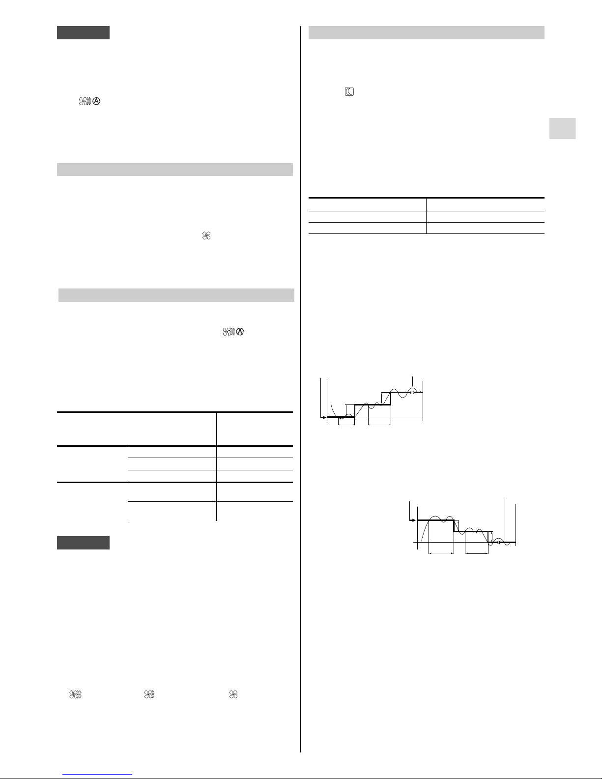
2
EG
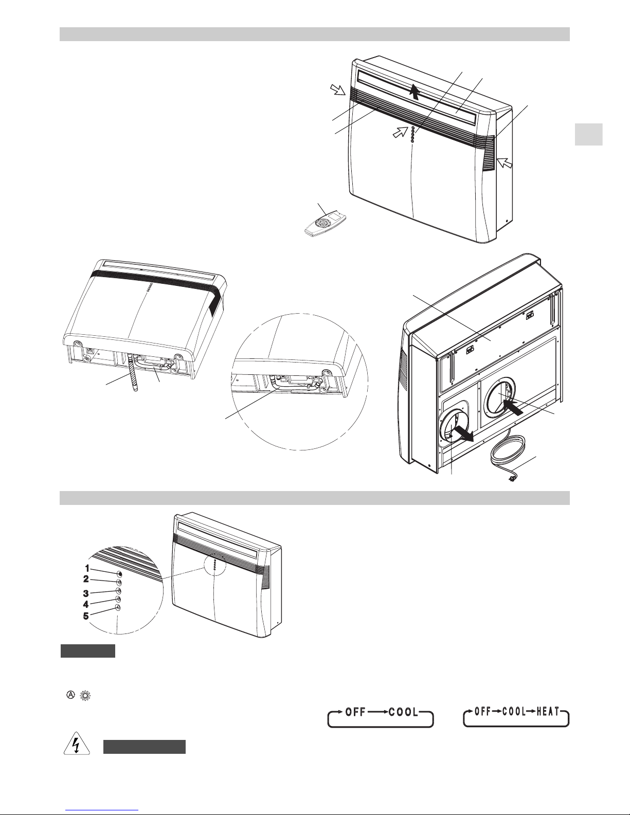
PRODUCT IDENTIFICATION
1. Wireless remote control unit
2. Signaling lamps
3. Supply air deflector
4. Lateral air intake grilles
5. Front air intake grille
6. Air filter
7. Electric cable with plug
8. Air inlet hole
9. Air outlet fan
10. Suspension panel
11. Service tube for condensate
discharge
12. Tube for condensate discharge
(heat pump models)
SIGNALING LAMPS
1. Receiver :receives signals transmitted from the remote
control.
2. Timer lamp: This lamp lights up when the system is
being controlled by the timer.
3. Standby lamp: This lamp lights up when the air
conditioner is connected to the power and ready to
receive the remote control command.
4. Operation lamp: This lamp lights up during operation.
It blinks once to announce that the remote control signal
has been received and stored. It blinks continuously
during the protection modes (defrosting, etc.).
5. Operation button (without remote control): Push the
button to change from one operation mode to the other
as shown here following.
The OFF position does not disconnect the power. Use
the main power switch to turn off power completely.
WARNING
Heat pump models
Cooling only models
1
2
3
4
5
6
7
8
9
10
11
11
12
Heat pump models
Cooling only models
NOTE
The blinking of OPERATION, TIMER and STANDBY
lamps, indicates that the operating mode selected
( ) is not compatible with the unit. If this happen
the air conditioner does not operate until the correct
mode is selected.
Page 4
3
EG
The installation should be carried out by a qualified installer,
following the instructions as shown.
INSTALLATION SITE SELECTION
● In case you should replace a radiator in an already existing
heating system, follow the instruction of the boiler
connection kit
● The wall must be a perimeter one.
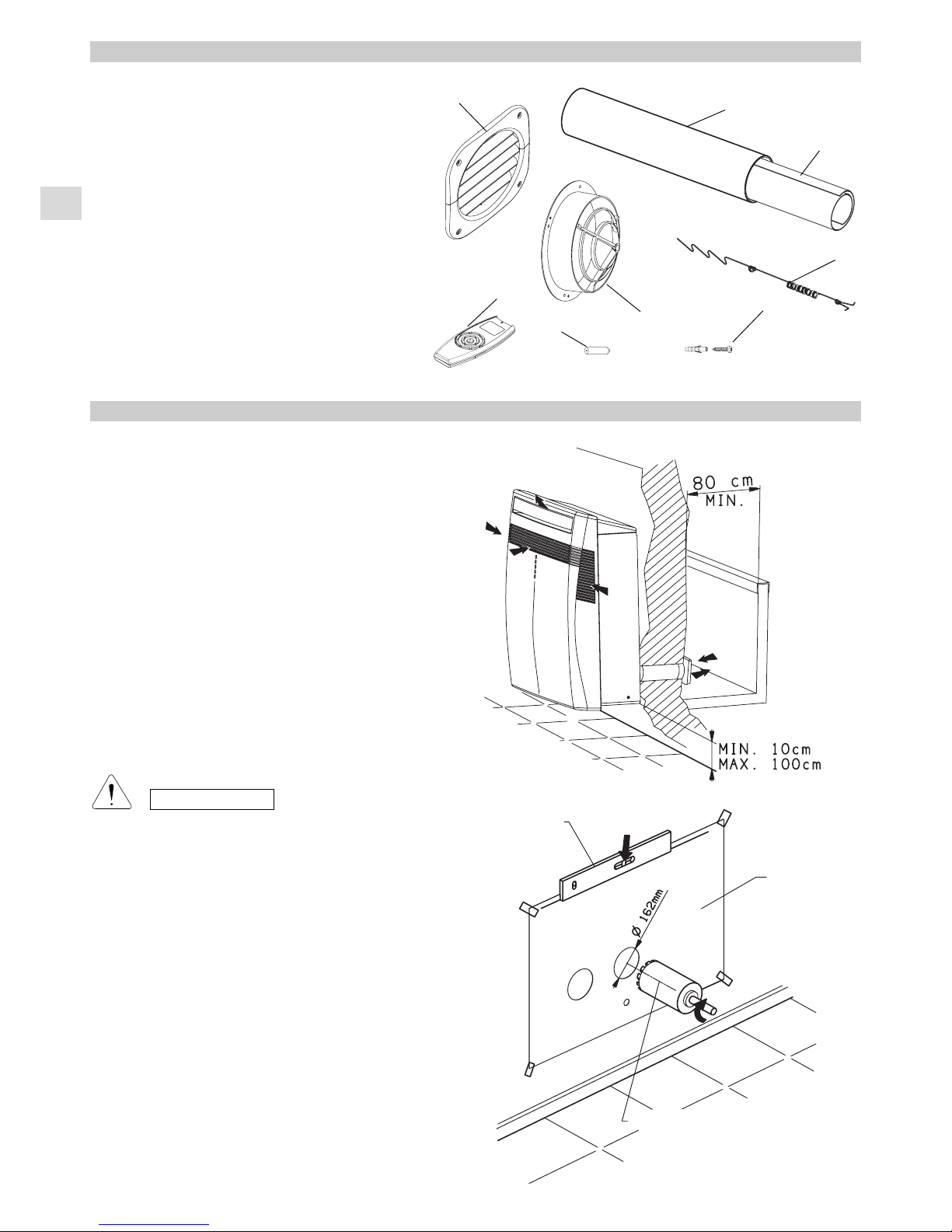
● Fix the unit at a minimum height of 10 cm and a maximum
height of 100 cm.
● Select a sufficiently strong location to support the weight
of the unit.
● Allow access for maintenance operation around the unit.
● Make sure that there are no obstacles around the unit
affecting the free circulation of air.
● Avoid installing the unit with the air flow directly toward
passerby people, electric appliances or heat sources.
CAUTION
After the selection of the installation site, according to
the above mentioned points, be sure not to make holes
in areas where electrical wiring or conduits are located,
damaging them.
Make sure that there are no obstacles in the conduits
inside the wall affecting the free circulation of the
external air. The unit must be kept at a minimum
distance of 80 cm from any wall or obstacle.
INSTALLATION
1. PLASTIC TUBE (1pcs.)
2. EXTERNAL GRILLES (2pcs.)
3. INTERNAL GRILLES (2pcs.)
4. TENSION BARS (2pcs.)
5. FULL SCALE DIAGRAM (1pcs.)
6. RAWLPLUGS + SCREWS (15pcs.)
7. REMOTE CONTROL UNIT (1pcs.)
8. BATTERIES FOR REMOTE CONTROL (2pcs.)
ACCESSORIES SUPPLIED WITH THE UNIT
5
1
2
3
4
6
8
Level
Full scale
diagram
Mill
MOUNTING OF THE UNIT
- Apply at the wall the full scale diagram, fix and level it.
- Drill the two holes Ø 162 mm and eventually the hole
Ø 35 mm in case of heat pump unit for the condensate
drainage toward the outside (assure a positive slope
toward the outside).
7
Page 5
4
EG
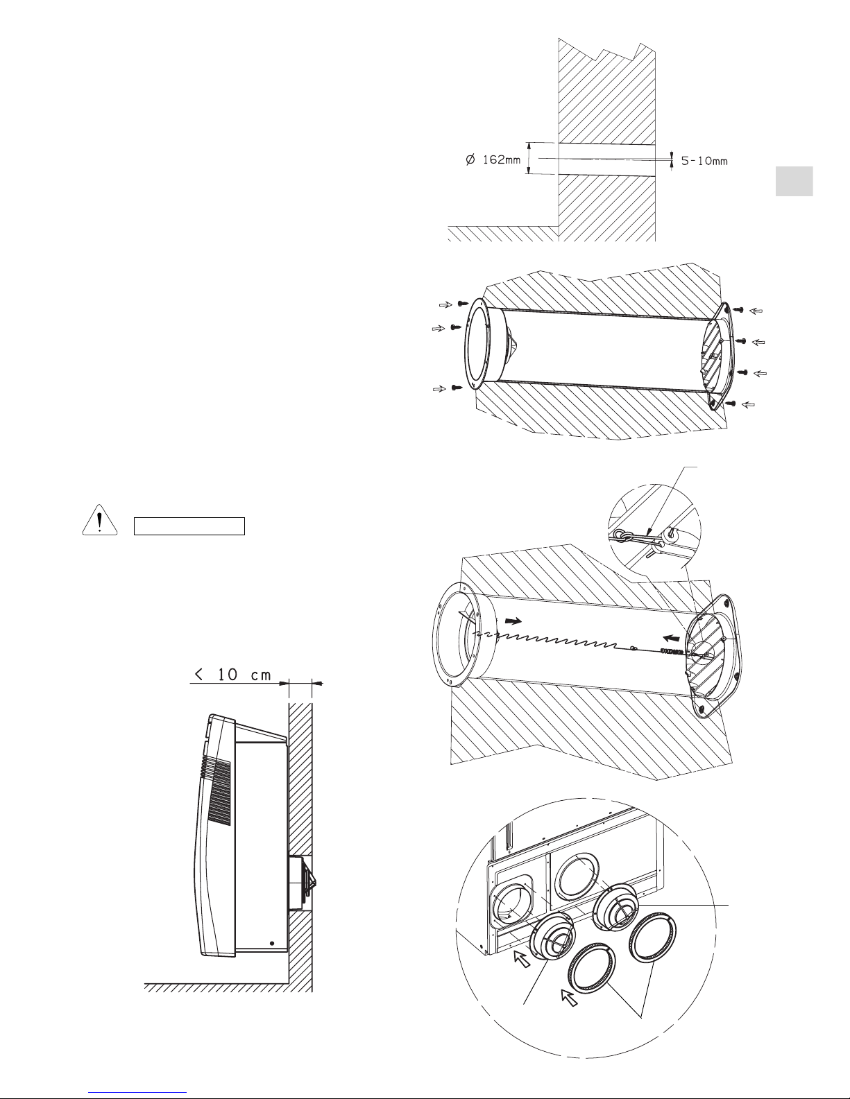
- Insert in the two holes the supplied plastic tube; cut it at
the right length: it is necessary to measure the thickness
of the wall and subtract 70 mm.
- Fix the two anti-intrusion grilles and the two external grilles
with the blades toward the bottom using wall rawl plugs
and screws.
- In case it is not possible to fix the two external grilles
directly at the wall, hook the two grilles to the internal
ones using the supplied tension bars, as follows:
a) Bend them, fix the hook of the spring, insert them
inside the tube and open them toward the outside.
b) Choose the proper hook of the tension bar in order to
lengthen the spring of 15-20 mm and hook it to the
internal grille.
c) Eliminate the exceeding part of the tension bar cutting
it near the hooking points.
Spring
hook
3
3
a
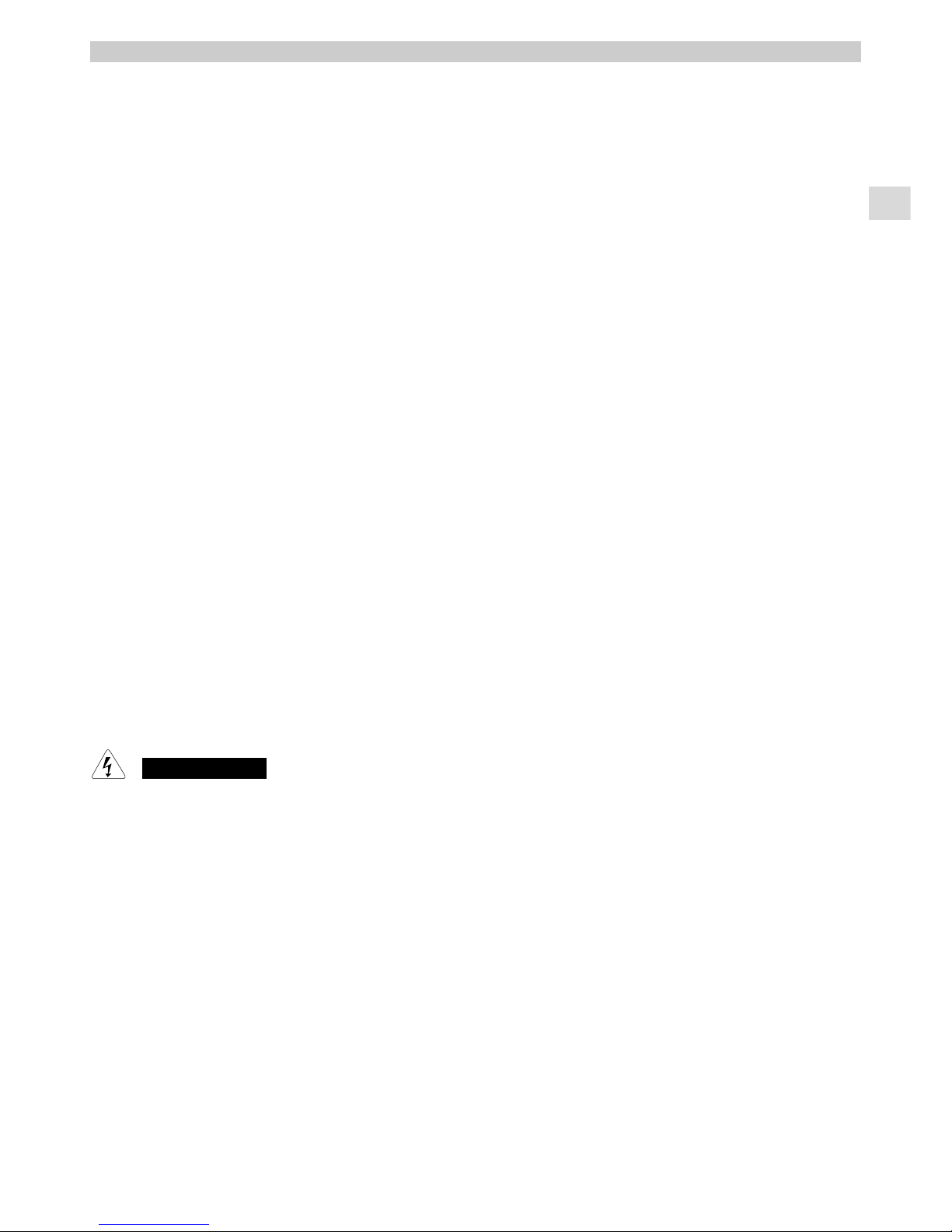
- In case of very thin walls (less than 10 cm) it is necessary
to mount the internal anti-intrusion grilles on the back of
the unit removing the gaskets (a) from the back side and
applying them around the grilles. The tube and the external
grilles will not be used.
CAUTION
The manufacturer assumes no responsibilities if this
safety instruction is not observed.
INSIDE
OUTSIDE
Page 6
5
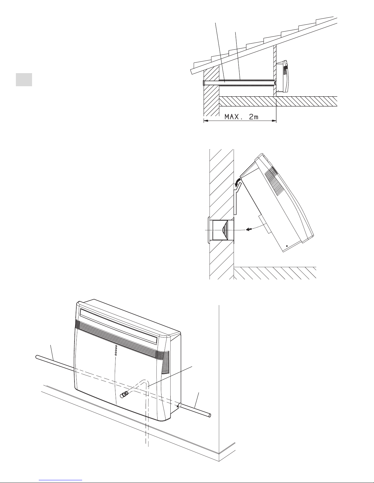
WARNING! The supplied plastic conduits can be used for
wall thickness up to 50 cm; in special cases (i.e. installations
in a garret) it can be necessary to utilise longer tubes. The
maximum allowable length is 2 m. Y ou can go to any building
material retailer, buy the plastic tube of the same diameter
(ø160 mm), of the proper length and cover it outside with
insulating material (thickness: about 3-4 cm).
- Fix the suspension panel to the wall in the position indicated
on the full scale diagram.
The quantity and the type of rawl plugs (not supplied)
depends on the consistence of the wall; do not let any
space between the panel and the wall.
- Hang up the unit at the panel inserting the back fan outlet
in the grille.
- In case of an heat pump model installation it is necessary
to predispose a condensate drainage toward the outside
(a) making a hole Ø 35 mm as indicated on the full scale
diagram; if it is not possible, maintain the condensate
tube inside (b) and make a proper drainage. Assure always
a positive slope of at least 1cm/m.
- Connect the unit inserting the plug in the power socket.
- Verify the correct operation.
EG
Plastic tubes ø 160mm
Insulation
(a)
(b)
(b)
Page 7
6
BEFORE USING THE APPLIANCE
● Check that the power supply at the location where the air conditioner is going to be used is 220-240V ~ 50Hz .
● Make sure that the electrical installation is suitable to supply continuously current necessary for the air conditioner in
addition to that already used by other electric appliances (white goods, lighting). See the max electric input indicated
on the name plate positioned on the air conditioner.
● The installation of a double-pole switch, protected by 10 Afuses of the delayed type, upstream the electricity wall socket,
is recommended.
● The unit has to be connected according to the local electrical rules.
● Make sure that circuit breakers, fuses, etc, are of sufficient capacity to handle a start-up current of 20 A(generally less
then 1 second).
● Do not install the air conditioner where it could be wetted by drops of water (i.e. in laundries).
● Before connecting the air conditioner to a power socket, make sure that the socket is provided with an earth connection
in compliance with local codes.
● Never use the power plug as a mean to start or stop the air conditioner: always use the ON/OFF button of the remote
control unit or the operation button on the unit.
● WARNING! Do not stick anything into the air outlet of the air conditioner. This is very dangerous because the fan is rotating
at high speed.
● WARNING!
The air conditioner is provided with a time-guard system, which does not allow re-starting of compressor until after 3
minutes from a previous stop.
● Make sure that there are no obstacles around the unit affecting the free circulation of air. Do not block the air intakes
and outlet of the unit with curtains or other. Never put objects on the top of the unit.
● When you switch on the air conditioner for the first time, it reaches the maximum efficiency after at least one hour of
operation.
● The manufacturer assumes no responsibilities if the safety regulations or local codes are not observed.
Always unplug the unit from the power socket before moving or cleaning it and, in case you should remove it, discharge
the eventual condensate water inside the bottom plate.
WARNING
EG
Page 8

EG
7
TEMPERATURE SENSOR SELECTOR
●
Under normal conditions the room temperature is detected
and checked by the temperature sensor placed in the
remote controller (I FEEL icon displayed ).This function
is designed to provide a personalised environment by
transmitting the temperature control command from the
location next to you. Therefore, when using this option,
the remote control should always be aimed, without
obstruction, at the air conditioner.
●
It is possible to disable the remote controller room sensor
pressing the I FEEL button. In this case the I FEEL icon
on the remote controller display lights off and the sensor
placed in the air conditioner becomes active.
HOW TO INSTALL BATTERIES
● Remove trhe lid in the rear part of the remote control unit
and check the settings of the dipswitch as shown below:
USING THE REMOTE CONTROL UNIT
OPERATION WITH THE REMOTE CONTROL UNIT
When using the remote control unit, always point the unit
transmitter head directly at the air conditioner receiver.
HOW TO TURN ON THE AIR CONDITIONER
Press the ON/OFF button to turn the air conditioner on.
The operation lamp will light up, indicating the unit is in
operation.
TRANSMITTER
HEAD
REMOTE
CONTROL UNIT
UNIT
RECEIVER
The remote control unit sends the temperature signal
at any key pressing and automatically every five
minutes. If, due to some troubles, the signal from the
remote is no longer detected, the air conditioner keeps
operating using the temperature sensor of the indoor
unit to control the room temperature. In this case, the
temperature around the remote control unit may differ
from the temperature detected in the air conditioner
position.
NOTE
●
Insert two AAA alkaline batteries of 1,5 V-DC making
sure that point in the direction marked in the battery
compartment.The displayed time flashes.
Press the SEL TYPE button.
Remote controller is now ready for operation.
●
The batteries last about six months. Depending on how
much you use the remote control unit.
Remove the batteries if you do not use the remote control
unit for more than one month.
Replace the batteries when the remote control unit lamp
fails to light, or when the air conditioner does not receive
the remote control unit signals.
●
The batteries of the remote control contain polluted
substances exhausted batteries must be disposed
according to the laws in force.
HOW TO REMOVE BATTERIES
● Remove the lid.
● Press the battery
toward the negative
end and lift it out by
its positive end (as
shown in the
figure).
● Remove the other
battery in the same
way.
Page 9

8
EG
REMOTE CONTROL UNIT
“NIGHT” BUTTON
For details, see "NIGHT MODE".
When you press this button in the COOL,
HEAT or DRY mode, the mark
appears on the display and the
microcomputer in the remote control unit
will adjust the set temperature to save
energy.
TRANSMITTER
When you press the buttons of the remote
control unit, the mark
appears on the display to transmit the
setting changes to the receiver in the air
conditioner.
TEMPERATURE SETTING BUTTONS
TEMP - (cooler)
Press this button to decrease the set
temperature.
TEMP + (warmer)
Press this button to increase the set
temperature.
SENSOR
A temperature sensor inside the remote
control unit detects the room temperature.
“SEL TYPE” BUTTON
Press this button in order to:
• set the clock
• set the ON/OFF timer
For details refer to paragraphs “SETTING
THE HOUR” and “SETTING THE TIMER”.
TEMPERATURE SENSOR SELECTOR
Press the I FEEL button to modify the
active setting for room temperature
detection (from remote controller to air
conditioner and viceversa)
“FAN “ BUTTON
Fan speed is automatically
selected by the microcomputer.
High speed.
Medium speed.
Low speed.
TIMER AND PRESENT TIME SETTING
BUTTONS
With these buttons is possible to set the
clock and the timer. For details refer to
paragraphs “ SETTING THE HOUR” and
“SETTING THE TIMER2.
“TIMER SEL” BUTTON
Press this button to select the type of
timer to activate. For details refer to
paragraph “SETTING THE TIMER”.
DISPLAY
Information is displayed when the remote controller is switched on. If switched off, only the operating mode, the room
temperature and the clock are shown
Operation mode
Fan speed
High speed
Automatic
Medium speed
Low speed
Displayed when
transmitting data
Set point
temperature
I FEEL mode is active
(remote controller
sensor active)
Timer modes
Automatic
Cooling
Heating
Dehumidification
Fan
MODE SELECTOR BUTTON
Press this button to modify the air conditioner mode.
(automatic)
(
When this setting is selected, the air conditioner
calculates the difference between the thermostat setting
and the room temperature and automatically switches to
the "cool" or "heat" mode.
(heating)
(
The air conditioner makes the room warmer.
(dry)
The air conditioner reduces the humidity in the room.
(cooling)
The air conditioner makes the room cooler.
(fan)
The air conditioner works only as a circulation fan.
(
Available only for models
COOL / DRY / HEAT /FAN
Clock
Room
temperature
Night
mode
Oscillation
Flap
PUSH-BUTTON FLAP
To press this push-button in order to
select the wished function.
: To press this push-button in
order to select the wished function.
: The baffle plate oscillates
automatically
INACTIVE BUTTONS
ON/OFF BUTTON
This button turns the air conditioner ON
and OFF.
Page 10

EG
9
HOW TO SET THE PRESENT TIME
COOLING
HEA TING (heat pump)
1. Press the button SEL TYPE three times.
The time indication alone flashes.
2. Press the SET H button until the present time hour
is displayed. Press the SET M button until the present
time minutes are displayed. The display will
automatically stop flashing.
THE DISPLAYSHOWS THE SELECTED
TEMPERATURE.
AFTER 5 SECONDS FROM THE REQUIRED
TEMPERATURE SETTING THE DISPLAY WILL
SHOW THE ROOM TEMPERATURE AGAIN.
4.Press the FAN button to select the fan speed.
ONON ON
Δ 1 H Δ 1 H
MIN. MAX.
A
B
C
C
B
A
27
26
25
24
23
22
21
20
19
AUTOMATIC OPERATION
1
4
3
2
Verify that the unit is connected to the
main power and the STANDBY lamp is
light up.
1.Set the MODE selector to COOL .
2.Press the ON/OFF button and switch the
air condioner ON.
3.Press the TEMP. buttons to set the desired
temperature (the temperature range is
between 32 °C max. and 16 °C min.).
NOTE
1.Set the MODE selector to HEAT .
2.Press the ON/OFF button and switch the air condioner ON.
3.Press the TEMP . buttons to set the desired temperature (the
temperature range is between 32 °C max. and 16 °C min.).
THE DISPLAYSHOWS THE SELECTED
TEMPERATURE.
AFTER 5 SECONDS FROM THE REQUIRED
TEMPERATURE SETTING THE DISPLAY WILL
SHOW THE ROOM TEMPERATURE AGAIN.
4.Press the FAN button to select the fan speed.
For several minutes after the start of heating operation, the
indoor fan will stop until the indoor heat exchanger coil has
warmed up sufficiently . This is because the COLD DRAFT
PREVENTION SYSTEM is operating. During this period, the
STANDBY lamp remains lit.
NOTE
DEFROSTING OF THE EXTERNAL HEAT
EXCHANGER
When the outdoor temperature is low, frost or ice may
appear on the heat exchanger coil, reducing the heating
performance. When this happens, a microcomputer
defrosting system operates. At the same time, the fan in
the indoor unit stops and the ST ANDBYlamp remains lit until
defrosting is completed. Heating operation restarts after
several minutes. (This interval will vary slightly depending
on the room and outdoor temperature).
HEATING PERFORMANCE
Aheat pump conditioner heats a room by taking heat from
outside air. The heating efficiency will fall off when the
outdoor temperature is very low. If enough heat is not
obtained with this air conditioner, use another heating
appliance in conjunction with it.
1.Set the MODE selector to AUTO .
2.Press the ON/OFF button and switch the air condioner
ON.
3.Press the TEMP. buttons to set the desired temperature
(the temperature range is between 32 °C max. and 16 °C
min.).
When this setting is selected, the air conditioner calculates
the difference between the thermostat setting and the room
temperature and automatically switches to the COOL or
HEA Tmode as appropriate.
4.Press the FAN selector button to the setting you want.
THE DISPLAYSHOWS THE SELECTED
TEMPERATURE.
AFTER 5 SECONDS FROM THE REQUIRED
TEMPERATURE SETTING THE DISPLAY WILL
SHOW THE ROOM TEMPERATURE AGAIN.
Example of operation diagram in the (Auto) mode with
the set room temperature at 23°C.
NOTE
The air conditioner changes the operation mode (from cool
to heat or vice versa, if one of the following conditions
occurs:
- ZONE A: changes if the difference between the room
temperature and the temperature set on the remote control
unit is at least 3°C..
- ZONE B: changes if the difference between the room
temperature and the temperature set on the remote control
unit is at least 1°C, one hour after the compressor stop.
- ZONE C: never changes if the difference between the
room temperature and the temperature set on the remote
control unit is no more than 1°C.
DEHUMIDIFYING (DRY)
1.Set the MODE button to DRY. The icon is displayed.
2.Press the ON/OFF button and switch the air condioner ON.
3.Press the TEMP. buttons to set the desired temperature (the
temperature range is between 32 °C max. and 16 °C min.).
THE DISPLAYSHOWS THE SELECTED
TEMPERATURE.
AFTER 5 SECONDS FROM THE REQUIRED
TEMPERATURE SETTING THE DISPLAY WILL
SHOW THE ROOM TEMPERATURE AGAIN.
Page 11
10
EG
WHEN DIFFERENCE BETWEEN
ROOM TEMPERATURE AND SET FAN SPEED
TEMPERATURE IS
Cooling and 2 °C and over High
dehumidifying Between 2 and 1 °C Medium
modes: Below 1 °C Low
2 °C and over High
Heating mode:
Below 2 °C Medium
ADJUSTING THE FAN SPEED
AUTOMATIC
Simply set the FAN selector to the position.A
microcomputer automatically controls the fan speed when
the AUT O mode is selected. When the air conditioner starts
operating, the difference between the room temperature
and the set temperature is detected by the microcomputer
which then automatically switches the fan speed to the
most suitable level.
1°C
1°C
1 hour
1 hour TIME
Setting temperature
Room temperature
COOLING AND DEHUMIDIFYING
1°C
1°C
1 hour 1 hour TIME
Setting temperature Room temperature
HEATING
NIGHT MODE
●
The NIGHT mode enables you to save energy.
1. Set the MODE selector to cool, dry or heat.
2. Press the NIGHT button.
3. The mark appears on the display. Press the NIGHT
button again to release the NIGHT function.
What does the NIGHT mode mean?
In this mode, the air conditioner will cool or heat the room
to the set temperature, and then the thermostat will make
the unit pause. After about 1 hour, the air conditioner will
automatically reset the set temperature as follows (also
refer to graphs).
OPERATING MODE SET TEMPERATURE CHANGE
Heating Lowered by 1 °C
Cooling and Dehumidifying Raised by 1 °C
When the room temperature reaches the new set value,
the thermostat will cause the unit to pause. After about 1
hour the temperature will be raised by 1 °C in cooling, or
lowered by 1 °C in heating. This enables you to save energy
without sacrificing your comfort.
NOTE
●
Use DRYoperation when you want to reduce the humidity
in the room.
●
Once the room temperature reaches the set level, the unit
repeats the cycle of turning on and off automatically.
●
During DRYoperation, the fan speed is automatically set
to or stops to prevent overcooling.
●
Dry operation is not possible if the indoor temperature is
15 °C or less.
FAN ONLY
If you want to make air circulate without any temperature control,
follow these steps:
1. Press the ON/OFF operation button and switch the air
conditioner ON.
2. Press MODE button until only the fan sign appears on
the display.
The above mentioned data make reference to the
conditioner operating when the sensor on the remote control
unit is ON. (Refer to temperature sensor selector). If the
sensor on the indoor unit is being used then actual operation
will slightly differ from that described in the above tables.
The automatic speed is not available in FAN ONLY mode.
High speed Med. speed Low speed
MANUAL
If you want to manually adjust speed just set the FAN selector
as desired.
NOTE
Page 12

EG
11
ADJUSTING THE AIR FLOW DIRECTION
Set vertical vanes to the front position during COOLING/DRY
operation if humidity is high.
If the vertical vanes are set to the left-most or right-most
position, condensation will form around the air outlet and
drip off.
CAUTION
TIMER SETTING PROCEDURE.
• Press four times the TIMER SEL
button.The 1 HOUR TIMER mark will
appear on the display.
CANCELLATION PROCEDURE
• Press the ON/OFF button to turn the air
conditioner off.
• Wait for the indoor unit to stop operating.
• Press the ON/OFF button again to turn
the air conditioner on.
SETTING THE 1 HOUR TIMER
This function causes the unit to operate for one hour at the set
conditions, regardless of whether the unit is on or off.
A) HOW TO SET THE ON TIME
1. Press the SEL TYPE button once.
The ON and time indications flash.
2. Press the SET H button until the designed
hour is displayed.
Press the SET M button until the designed
minutes are displayed. The display will
change automatically back to show the
present time after 10 sec.
3. Press the ON/OFF button to start the air
conditioner.
4. Press the TIMER SEL button to activate
the ON timer.
B) HOW TO SET THE OFF TIME
1. Press the SEL TYPE button twice.
The OFF and time indications flash.
2. Press the SET H button until the designed
hour is displayed.
Press the SET M button until the designed
minutes are displayed. The display will
change automatically back to show the
present time after 10 sec.
3. Press the ON/OFF button to start the air
conditioner.
4. Press the TIMER SEL button two times to
activate the OFF timer.
C) HOW TO SET A PROGRAM FOR DAILY
ON/OFF OPERATION (OR VICEVERSA)
1. Set the timer ON/OFF as shown in A) and
B).
2. Press the ON/OFF button to start the air
conditioner.
3. Press three times the TIMER SELECT
button to activate the DAILYtimer.
SETTING THE TIMER
After timer setting, press PROGRAM button in order to check the
ON/OFF setting time.
NOTE
2
1
4
3
HORIZONTAL(manual)
The horizontal air flow can be adjusted by moving the vertical
vanes to the left or right, as indicated in the following figures.
VERTICAL (with remote control unit)
Make sure that the remote control unit has been turned on. Press
the FLAP button to select the sweep function or to choose one of
the six positions of the flap.
CAUTION
Do not move the flap with your hands when the air conditioner
is running.
Vertical vane
Sweep function
The flap starts moving up and down to deliver air over the
sweep range.
NOTES
• The flap automatically closes when the unit is off.
• During the heating operation, the fan speed will be very low and
the flap will be in the horizontal position (position d) until the air
being blown out of the unit begins to warm. Once the air warms
up, the flap position and fan speed change to the settings
specified with the remote control.
• Use the FLAP button on the remote control to adjust the
position of the flap. If you move the flap by hand, the factual
flap position and the flap position on the remote control
may no longer match. If this should happen, shut off the
unit, wait for the flap to close, and then turn on the unit
again; the flap position will now be normal again.
CAUTION
Page 13

12
EG
2. WHEN THE AIR CONDITIONER IS RUNNING
If you want to turn off the air conditioner push the
OPERA TION BUTTON until the OPERATION lamp is turned
off.
If you have lost the remote control unit or it has troubles,
follow the steps below.
1. WHEN THE AIR CONDITIONER IS STOPPED
If you want to turn on the air conditioner push the
OPERATION BUTTON to select the desired mode:
• COOL or HEAT for heat pump models
• COOL for cooling only models
OPERATION WITHOUT THE REMOTE
CONTROL UNIT
TIPS FOR ENERGY SAVING
DO NOT:
●
Block the air intake and outlet of the unit.
If they are obstructed, the unit will not work well, and
may be damaged.
●
Let direct sunlight into the room. Use sunshades,
blind or curtain.
DO:
●
Always try to keep the air filter clean. A clogged filter
will impair the performance of the unit.
●
T o prevent conditioned air from escaping, keep windows,
doors and any other openings closed.
●
The room temperature is above 16°C for cooling and
dehumidification mode.
The air conditioner will start in HIGH fan speed.
The temperature setting is 25°C for cooling mode and
21°C for heating mode.
NOTE
WARNING
• The use of portable telephones near the air conditioner
may cause disturbance to its normal operation and must
be avoided. In case abnormal operation is noticed,
(OPR operation lamp lights (4) but the air conditioner will
not run) to restore normal operation turn-off electric supply
for 60 seconds at least, by disconnecting the main switch
or the wall plug, then start again the air conditioner.
• If your air conditioner does not work properly, first check
the following points before requesting service.
If it still does not work properly, contact your dealer or
service centre.
Power failure during operation.
In the event of power failure, the unit will stop. When the
power is resumed, the unit will restart automatically after 3
minutes.
NOTE
Operation
button
Heat pump models
Cooling only models
TROUBLESHOOTING
Trouble: the air conditioner does not run at all.
Possible cause:
1. Power failure.
2. Leakage breaker tripped.
3. Line voltage is too low.
4. Operation button is OFF.
5. Batteries in remote control unit have run down.
6. The selector of the boiler connection kit is not in the
right position.
Remedy:
1. Restore power.
2. Contact service centre.
3. Consult your electrician or dealer.
4. Press the button again.
5. Replace batteries.
6. Put the selector in the position with the symbol “air
conditioner”.
Trouble:The air conditioner does not operate and standby
lamp (3) flashes .
Possible cause:
1. Defective sensor.
Remedy:
1. Contact service centre.
Trouble:STANDBYand OPERATION lamps flash and the
air conditioner does not operate.
Possible cause:
1. Air conditioner coil sensor defective.
Remedy:
1. Contact service centre.
Trouble: Compressor runs but soon stops.
Possible cause:
1. Obstruction of the air intake grilles.
Remedy:
1. Remove obstruction.
Trouble: Poor cooling or heating performance.
Possible cause:
1. Dirty or clogged air filters.
2. Heat source or many people in room.
3. Doors and/or windows are open.
4. Obstacle near air intake or air discharge port.
5. The set temperature on the remote control unit is too
high.
6. Outdoor temperature is too low (heat pump version).
7. Defrosting system does not work (heat pump version).
Remedy:
1. Clean air filters to improve airflow.
2. Eliminate heat source if possible.
3. Shut them to keep the heat or cold out.
4. Remove it to ensure good airflow.
5. Set the right temperature on the remote control unit.
6. Try to use a back-up heater.
7. Consult your dealer.
NOTE
The blinking of OPERATION, TIMER and STANDBY
lamps, indicates that the operating mode selected
( ) is not compatible with the unit. If this happen
the air conditioner does not operate until the correct
mode is selected.
Page 14

Trouble: Clicking sound is heard from the air conditioner.
Possible cause:
1. During operation, any plastic parts may expand or shrink
due to a sudden temperature change. In this event, a
clicking sound may occur.
Remedy:
1. This is normal, and the sound will disappear when an
even temperature is settled.
13
Trouble: Operation lamp (4) flashes, the fan operates,
while the compressor stops.
Possible cause:
1. Safety float switch operating due to excessive
condensate in the unit.
Remedy:
1. Discharge the condensate (see paragraph “HOW TO
DISCHARGE THE CONDENSATE W ATER”).
EG
●
Always switch off the air conditioner before unplugging
it from the power socket.
●
Always unplug the air conditioner before discharging the
condensate water collected inside.
WARNING
The Humidity removed by the unit is collected and
discharged automatically, but in special conditions some
condensate water could remain inside the unit.
If you are not going to make use of the air conditioner for
a long period, it is necessary to discharge the eventual
condensate water through the service tube for condensate
discharge placed under the bottom of the unit.
At the end of the operation close the tube with its stopper.
HOW TO DISCHARGE THE CONDENSATE WATER
IMPORTANT
Page 15
14
BOYLER CONNECTION KIT (ONLY FOR 245C-235H MODELS)
The unit is predisposed to replace a radiator in an already existing heating system. it is necessary to buy the boyler
connection kit that can be installed on both side of the unit according of the position of the water connections.
CARE AND CLEANING
WARNING! For safety’s sake, be sure to turn the air conditioner
OFF and also disconnect it from the power supply before cleaning
it.
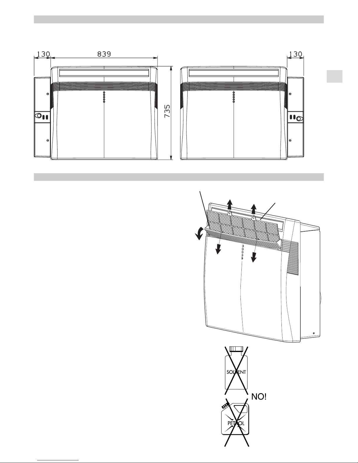
1. Cleaning of the Air Filter
The air filter must be checked at least once every two weeks
operation. Operation with a dirty filter always causes a lower
efficiency of the air conditioner and severe product damage.
The filter is located at the back of the front intake grille: open
the grille pulling downward the two hooks, grasp the air filter and
pull upwards. Use a vacuum cleaner to remove light dust. If
there is sticky dust on the filter, wash it with lukewarm soapy
water, then rinse in clean, cold water and dry it before
reinstallation.
2. Cleaning of Casing and Grilles.
T o clean the air conditioner, wipe it with a clean soft cloth, lightly
moisted. In case it is stained, moisten the cloth with soapy
water. Never use solvents or harsh chemicals, nor very hot
water. Do not pour water over the air conditioner to clean it:
this will damage the internal components and cause an electric
shock hazard.
3. After use.
If you are not going to make use of the air conditioner for a
long period, clean the air filter and verify that there is no
condensate water inside the bottom of the unit (see paragraph
“HOW TO DISCHARGE THE CONDENSATE WATER”). Do
not put heavy objects on top of the unit.
4. Transport.
Keep the air conditioner in the vertical position during
transportation.
5. For your safety care check periodically the conditions of
the electric supply cable; the electrical connection of the
unit is Y type with cable prepared in a special way; in case
you should notice any damage due to usage, call the
nearest After Sale Service to get the cable replaced.
EG
Air filter
Intake grille
Page 16

EG
I
F
D
E
P
BLK BLACK
NERO
NOIR
SCHWARZ
NEGRO
PRETO
BLU BLUE
BLU
BLEU
BLAU
AZUL
AZUL
BRN BROWN
MARRONE
MARRON
BRAUN
MARRÓN
CASTANHO
GRN / YEL GREEN / YELLOW
VERDE / GIALLO
VERT / JAUNE
GRÜN / GELB
VERDE / AMARILLO
VERDE / AMARELO
GRY GREY
GRIGIO
GRIS
GRAU
GRIS
CINZENTO
ORG ORANGE
ARANCIONE
ORANGE
ORANGE
NARANJA
COR-DE-LARANJA
PNK PINK
ROSA
ROSE
ROSA
ROSA
COR-DE-ROSA
RED RED
ROSSO
ROUGE
ROT
ROJO
ENCARNADO
VLT VIOLET
VIOLA
VIOLET
VIOLETT
VIOLETA
VIOLETA
WHT WHITE
BIANCO
BLANC
WEISS
BLANCO
BRANCO
YEL YELLOW
GIALLO
JAUNE
GELB
AMARILLO
AMARELO
AZU LIGHT BLUE AZZURRO AZUR HIMMEL BLAU AZUL CLARO AZUL CLARO
SYMBOL EG
I
F
D
E
P
PC - DP CONDENSATE PUMPMOTOR
MOTORE POMPA CONDENSA
MOTEUR POMPE CONDENSATION
KONDENSWASSERPUMPE-MOTOR
MOTOR BOMBADE AGUA MOTOR BOMBA DE AGUA
CM COMPRESSOR MOTOR
MOTORE COMPRESSORE
MOTEUR DE COMPRESSEUR
KOMPRESSORMOTOR
MOTOR DEL COMPRESOR
COMPRESSOR
C1, 2, 3,4 CAPACITOR
CONDENSATORE
CONDENSATEUR
KONDENSATOR
CONDENSADOR
CONDENSADOR
DEF THERMO DEFROST THERMOSTAT
TERMOSTATO SBRINATORE
THERMOSTAT DE DEGIVRAGE
ENTFROSTER-THERMOSTAT
TERMOSTATO DE DESCONGELACION
TERMOSTATO DE DESCONGELAÇAO
FLP FLAP MOTOR
MOTORE DEFLETTORE
MOTEUR DE VOLET
KLAPPENMOTOR
MOTOR DEL DEFLECTOR
MOTOR DA PLACA
LM LOUVER MOTOR
MOTORE DEFLETTORE
MOTEUR D’AUVENT
LUFTKLAPPENMOTOR
MOTOR CON ABERTURAS
MOTOR COM ABERTURAS LATERAIS
FMO OUTDOOR FAN MOTOR
MOTORE ESTERNO VENTOLA
MOTEUR DE VENTILATEUR EXTERIEUR
AUSSENLÜFTERMOTOR
MOTOR EXTERIOR DE LATURBINA
MOTOR DA VENTOINHA EXTERIOR
FMI, FM INDOOR FAN MOTOR
MOTORE INTERNO VENTOLA
MOTEUR DE VENTILATEUR INTERIEUR
INNENLÜFTERMOTOR
MOTOR INTERIOR DE LATURBINA
MOTOR DA VENTOINHA INTERIOR
IND. ASSY INDICAT OR ASSY
GRUPPO INDICATORI
ENSEMBLE INDICATEUR
EANZEIGE-BAUGRUPPE
GRUPO DE INDICADORES GRUPO DE INDICADORES
MG MAGNETIC CONTACTOR
CONTATTORE MAGNETICO
CONTACTEUR MAGNETIQUE
MAGNETKONTGEBER
CONTACTOR MAGNÉTICO
CONTADOR MAGNÉTICO
NF NOISE FILTER
FILTRO RUMORE
FILTRE ANTI P ARASSITE
LÄRMSCHUTZFILTER
FILTRO DELRUIDO
FILTRO DE RUÍDO
OLR OVERLOAD RELAY
RELÉ SOVRACCARICO
RELAIS DE SURCHARGE
ÜBERLASTRELAIS
RELÉ DE SOBRECARGA
RELÉ DE SOBRECARGA
CE - PCB CONTROLLER
SCHEDA ELETTRICA
CARTE ELECTRONIQUE
STEUERGERÄT
CONTROLADOR
PAINELELÉTRICO
PR POWER RELAY
RELÉ ALIMENTAZIONE
RELAIS D’ALIMENTATION
LEISTUNGSRELAIS
RELÉ DE ALIMENTACIÓN
RELÉ DAALIMENTAÇAO
RP PUMP RELAY
RELÉ POMPA
RELAIS POMPE PUMPE
RELAIS
RELÉ BOMBA DE AGUA
RELÉ BOMBA
SSR SOLID STATE RELAY
RELÉ STATO SOLIDO
RELAIS A SEMI-CONDUCTEUR
FESTKÖRPERRELAIS
RELÉ DEL ESTADO SÓLIDO
RELÉ DO ESTADO SÓLIDO
RA STARTING RELAY
RELÉ DI AVVIAMENTO
RELAIS DE DEMARRAGE
STARTRELAIS
RELÉ DE ARRANQUE
RELÉ DE ARRANQUE
SV SOLENOID VALVE
VALVOLA SOLENOIDE
ELECTROVANNE
MAGNETVENTIL
VÁLVULASOLENOIDE
VÁLVULASOLENÓIDE
MS - FS SAFETY FLOAT SWITCH
INT. SICUREZZAA GALL.
INTERR. DE SECURITE AFLOTTEUR
SCHWEMM-SCHUTZSCHALTER
INTERR. DE SEGURIDAD DE FLOTADOR
INTERR. DE SEGURANÇA
ON-OFF SW ON-OFF SWITCH
INTERRUTTORE MARCIA/ARRESTO
TOUCHE MARCHE/ARRÊT
EIN/QUS TQSTE
BOTON ARRANQUE/P ARADA INTERRUPTOR LIGAR/DESLIGAR
TH1, 2, THERMISTOR
TERMISTORE
THERMISTANCE
THERMISTOR
TERMISTOR
TERMISTOR
P TIMER
PROGRAMMATORE
PROGRAMMATEUR
ZEITSCHALT-UHR
PROGRAMADOR TIMER
TR1, 2 POWER TRANSFORMER
TRASFORMATORE DI POTENZA
TRANSFORMATEUR DE PUISSANCE
NETZTRANSFORMATOR
TRANSFORMADOR DE POTENCIA
TRANSFORMADOR DE CORRENTE
20S 4-WAY VALVE
VALVOLA 4 VIE
VANNE 4 VOIES
4-WEG-VENTIL
VÁLVULADE 4 VÍAS
VÁLVULADE 4 VIAS
47C NEGATIVE PHASE RELAY
RELÉ A FASE NEGATIV A
RELAIS D’ORDRE DE PHASE
NEGATIVPHASENRELAIS
RELÉ DE FASE NEGATIVA
RELÉ DA FASE NEGATIVA
HWC HOT WATER CONTROL SCHEDACONTROLLO ACQUACALDA CARTE ELECTRONIQUE EAU CHAUDE WARMWASSER-
STEUERGERÄT CONTROLADOR AGUA CALIENTE PLACA DE CONTROLO AGUAQUENTE
TM LIMIT WATER THERMOSTAT TERMOSTATO LIMITE ACQUA THERMOSTAT DE SEC. NIVEAU EAU WASSERGRENZE-THERMOSTAT TERMOSTATO LIMLITE AGUA TERMOSTATO LIMITE AGUA
EWV WATER ELECTRIC VALVE
E
lectric wiring diagrams’ symbols /
Simboli schemi elettici
/ Symboles des schemas électriques /
Symbole der System-Schaltplanen
Símbolos de los esquemas eléctricos /
Símbolos
dos esquemas elétricos
Wires color legend
Legenda colori fili elettrici
Légende des couleurs des fils électriques
Beschriftung der Leitungs-Farben
Leyenda de los colores de los cable electricos
Legenda das côres dos fios elétricos
ELETTROVALVOLA PASS. ACQUA VENTIL (WASSER-DURCHFLUSS) VALVULAFLUJO DE AGUA VALVULA PASSAGEM DE AGUA
ELECTROVANNE PASSAGE EAU
R.D. 28 Reyrieux BP 131 - 01601 Trévoux CEDEX France
Tél. 04.74.00.92.92 - Fax 04.74.00.42.00
R.C.S. Bourg-en-Bresse B 759 200 728
In order to carry on a constant improvement, our products can be modified without prior notice.
Per garantire un costante miglioramento dei nostri prodotti, ci riserviamo di modificarli senza preavviso.
Par souci d’amélioration constante, nos produits peuvent être modifiés sans préavis.
Unsere Produkte werden laufend verbessert und können Vorankündigung abgeändert Werden.
En el interés de mejoras constantes, nuestros productos pueden modificarse sin aviso prévio.
printed in italy
 Loading...