

Page 1
Industrial Fluidised Baths
IFB-51 and IFB-52
Instruction Manual
7002661 / Version 5
Page 2

CONTENTS
2
IMPORTANT SUPPLEMENTARY SAFETY INFORMATION 3
GENERAL DESCRIPTION 4
BEFORE USE 5
SAFETY AND INSTALLATION 6
English 6
Français 8
Deutsch 10
Español 12
Italia 14
WARNING 16
PRINCIPLE OF OPERATION AND SAFETY FEATURES 17
DESCRIPTION OF COMPONENTS AND FRONT PANEL CONTROLS 18
INSTALLATION 19
Set-up 19
OPERATION 20
Start-Up 20
Air adjustment 20
Bath temperature 20
Extraction Air setup 20
Shut-Down 21
PID Temperature Controller 21
THE CLEANING PROCESS 22
FUME IGNITION 23
FUME EXTRACTION AND CLEANING 24
OPERATOR MAINTENANCE 25
Special maintenance procedures when burning off PVC or other halogenated polymers 26
FAULT FINDING 27
SERVICE, REPAIR AND TECHNICAL SUPPORT 28
Warranty 28
TECHNICAL SPECIFICATION 29
REPLACEMENT PARTS 30
ACCESSORIES 30
DECLARATION OF CONFORMITY 31
Page 3
IMPORTANT SUPPLEMENTARY SAFETY INFORMATION
3
Introduction
Techne fluidised baths are safe and effective equipment when installed and operated correctly in
accordance with the user manual. However, if used incorrectly they can pose a safety risk. Techne have
designed all models of fluidised baths to protect operators from hazards but users should pay attention to
the following points.
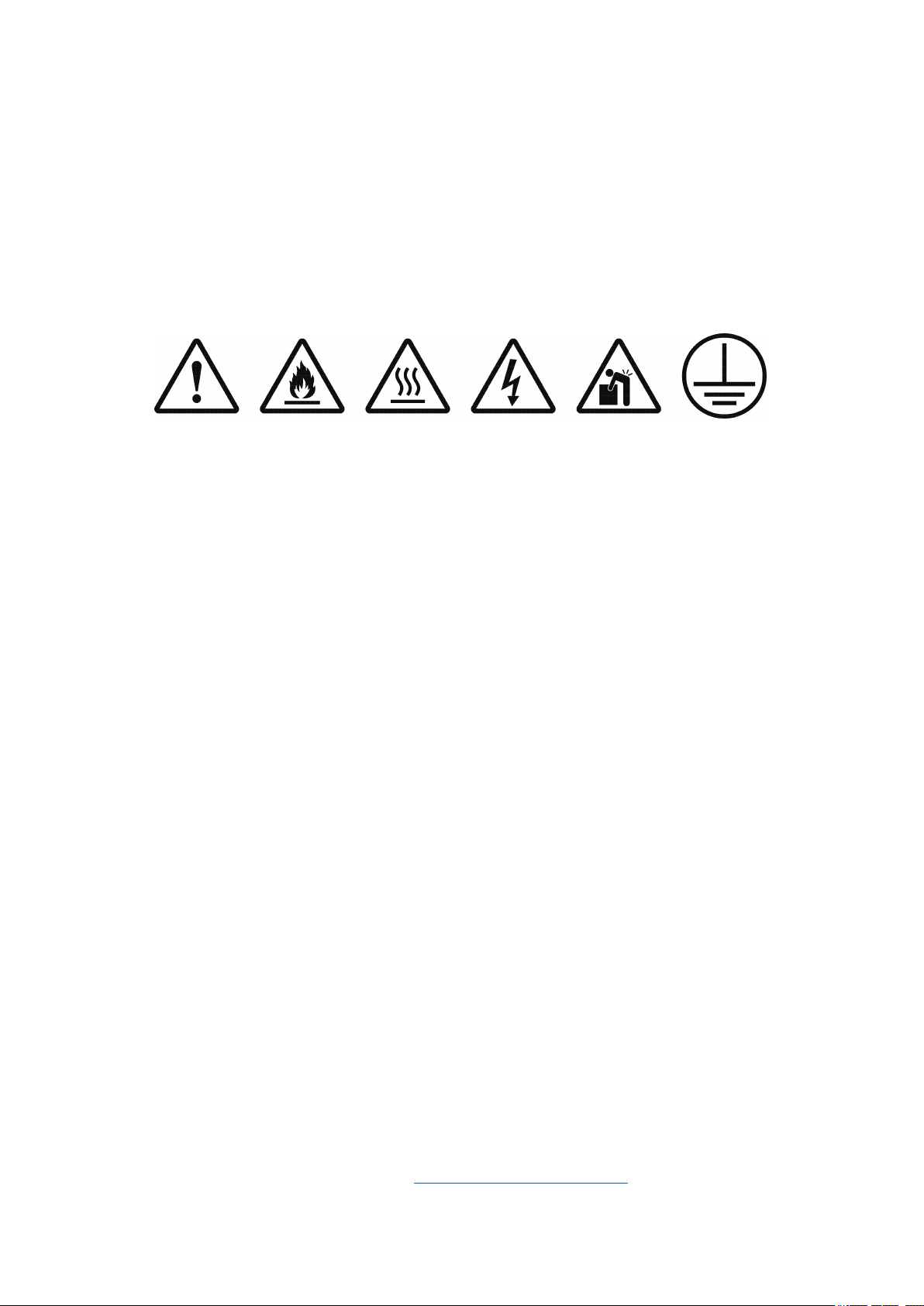
Symbols Defined
WARNING
Caution
1. Please read the Instruction Manual before installation and use.
2. Some Techne fluidised baths can heat up to 700°C. High temperatures are dangerous and can cause
serious burns to operators and ignite combustible material.
3. Use care and wear protective gloves to protect hands and protective glasses to protect eyes.
4. Do not put hot objects on or near combustible objects.
5. Do not operate the unit close to inflammable liquids or gases.
6. Do not place any liquid directly in the unit.
7. Always ensure a suitable, adequate ventilation system is used when equipment is in use.
8. Always install fireproof metal ducting with sufficient airflow where applicable.
Maintenance
1. When performing maintenance, always disconnect from power supply and cool below 50°C.
2. Techne recommend regular cleaning of fluidised baths. Externally, wipe with a damp soapy cloth. No
abrasive cleaners should be used. Care should be taken to prevent any water entering the unit.
3. Regular internal and external inspection of extraction ducting is recommended to detect any damage
and ensure the internals are clean. Any build-up of particles or debris discovered in the extraction
ducting requires the ducting to be cleaned or replaced.
4. In fluidised baths used for polymer burn-off, please regularly inspect fluidising medium, remove any
foreign debris and replace with clean fluidising medium as required.
5. Never top-up a hot fluidised bath with cold fluidising medium. Always cool below 50°C first.
FIRE
HAZARD
HOT
SURFACE
RISK OF
ELECTRIC
SHOCK
HEAVY OBJECT
2 PERSON LIFT
REQUIRED
EARTH
Please note:
1. Please ensure an adequate risk assessment is performed before use of a fluidised bath.
2. Please ensure the appropriate temperature is used for the application, always stay safely below the
combustion temperature of any material or sample in a fluidised bath.
3. Fluidising airflow must be switched on before heating a fluidised bath and left operational until the
bath cools to below 50°C.
4. Do not overfill fluidising media. When fluidized, the aluminium oxide level should be approximately
100mm (4”) from the top surface of the bath at your maximum operating temperature.
5. In fluidised baths used for polymer burn-off, always remove excess polymer from sample.
6. In applications where materials being treated produce acidic vapours during thermal decomposition, it
is recommended a fume scrubber is utilised to ensure fume emission from the plant conforms to local
regulations.
7. If you have any questions, please contact cptechsupport@coleparmer.com
.
Page 4

GENERAL DESCRIPTION
4
The Techne Indust
residue from extruder tools, moulding machine tools and associated parts.
The fluidised bath employs the principle of fluidisation of a mass of finely divided inert particles by means
of an upward flow of gas. A state of fluidisation is achieved when the individual particles become
microscopically separated from each other by the moving gas. This “fluidised bed” of particles has unusual
properties which differ markedly from either those of the gas or of the solid particles. Instead, the fluidised
bed behaves remarkably like a liquid, exhibiting characteristics which generally attribute to a liquid state.
For example, the fluidised bed can be agitated and bubbled; it always seeks a common level; materials of
less density will float while those with densities greater than the equivalent fluidised bed density will sink;
and, most important, the heat transfer characteristics between the fluidised bed and a solid interface can
have an efficiency approaching that of an agitated liquid.
In addition, the fluidised solid phase has a most unusual physical behaviour, in that its basic characteristics
change only slightly over very large temperature ranges; it has no melting point and no boiling point. The
lowest temperature available is the liquefaction point of the gas used for fluidisation, while the highest
temperature level is the usable temperature of the inert solid. Various metal oxides with allowable
temperatures of over 1700°C are readily available. The metal oxide beds commonly used, (e.g. aluminium
oxide) are non-flammable, non-explosive and non-toxic.
The most commonly used fluidising gas is compressed air. It is important that it should be clean, dry, free
from oil and at a constant pressure. Any other inert gas, such as nitrogen, could be used for special
applications e.g. if a non-oxidising atmosphere is required, provided appropriate precautions are taken.
rial Fluidised Baths IFB-51 and IFB-52 have been specially designed for removing plastic
The unique characteristics of gas-fluidised particles is the relatively high rate of heat transfer which yields
highly isothermal conditions, as well as excellent heat transfer to solid surfaces. This characteristic is due to
the turbulent motion and rapid circulation rate of the solid particles in conjunction with the extremely high
solid-gas interface area. Therefore, even though gas-solid interfaces normally yield low heat transfer
coefficients and the solids normally have low thermal conductivities, the overall heat transfer characteristics
of fluidised particles approach those of a liquid.
The combination of excellent heat transfer characteristics and high heat capacity are ideal for attaining
rapid stabilisation at an isothermal condition.
Techne industrial fluidised baths use alundum - fused brown aluminium oxide - as the fluidising medium.
They have been designed to remove plastic residue from extruder and moulding machine tools, paint build
up from paint fixtures and carry out various heat treatment processes. When used for burning plastic
residues, the IFB’s should be installed with an adequate fume extraction system. An extraction fan and
fume extraction collar can be supplied.
Page 5

BEFORE USE
5
Thank you for purchasing this Techne product. To get the best performance from the equipment, and for
your own safety, please read these instructions carefully before use. If there is any doubt relating to the
proper use of this equipment, the staff at Cole-Parmer Ltd. or your supplier will be happy to assist you.
UNPACKING
When unpacking the unit please ensure that the following have been removed from the packaging:
Part code
FIFB51D or FIFB52D
7002661
Please note that the aluminium oxide fluidising medium must be ordered separately:
Part code Item description
Brown/ALO Alundum - brown aluminium oxide, 25kg.
The IFB-51 requires 40kg of aluminium oxide and the IFB-52, 73kg of aluminium oxide.
The user is advised to keep the original packaging in case the instrument ever needs to be returned for
service or repair. Cole
packed and transported in its original packaging.
If the equipment is not used in the manner described in this manual and with accessories other than those
recommended by the manufacturer, the protection provided may be impaired.
Item description
IFB Industrial fluidised bath
Instruction manual
Eurotherm controller instructions
Warranty card
-Parmer Ltd. accepts no responsibility for damage incurred unless the unit is correctly
Page 6

SAFETY AND INSTALLATION
6
Please read all the information in this Instruction Manual before using the unit.
WARNING
HIGH TEMPERATURES ARE DANGEROUS: they can cause serious burns to operators and ignite
combustible material.
Techne have taken great care in the design of these units to protect operators from hazards, but
operators should pay attention to the following points:
• USE CARE AND WEAR PROTECTIVE GLOVES TO PROTECT HANDS AND SAFETY GLASSES TO
PROTECT EYES.
• DO NOT use combustible substances near hot objects.
• DO NOT operate the instrument in the vicinity of inflammable liquids or gases.
• DO NOT place any liquid directly into the instrument.
• At all times USE COMMON SENSE.
OPERATOR SAFETY
All operators of Techne equipment must have available the relevant literature needed to ensure their
safety. It is important that only suitably trained personnel operate this equipment in accordance with the
instructions contained in this manual and with general safety standards and procedures. If the equipment
is used in a manner not specified by Techne the protection provided by the equipment to the operator
may be impaired.
All Techne units have been designed to conform to international safety requirements and are fitted with
an over-temperature cut-out. On some models, the cut-out is adjustable and should be set to suit the
application. On all other models the cut-out is pre-set to protect the unit.
If a safety problem should be encountered, switch off at the mains power supply.
INSTALLATION
Before connecting the instrument to the mains electricity supply, check the voltage against the
rating plate (located on the back of the unit). Please note that the unit must be earthed to
ensure proper electrical safety.
Connections 220V-240V
Live Brown
Neutral Blue
Earth Green/yellow
Note: The IFB-51 and IFB-52 are classified as “Permanently Connected Equipment” and should be
connected to the electricity supply by a qualified electrician.
A suitable supply for the IFB-51 is rated at 4kW, 220-240V, 50/60Hz~ single phase.
A suitable supply for the IFB-52 is rated at 6kW, 220-240V, 50/60Hz~ single phase.
The equipment is supplied with 2.5m of flexible, triple core, circular cable to the following specification:
4.0mm², to BS 6500 or equivalent and <HAR> or BASEC approved. Connection to the mains electrical
supply should be via a double pole 30mA Residual Current Breaker with Overcurrent protection (RCBO)
isolating circuit breaker switch with a continuous current carrying capacity of 30A at 250V and
overcurrent of 30A.
Do not switch on until the unit is fully installed.
Page 7

ENVIRONMENTAL CONDITIONS
7
This equipment is designed to operate under the following conditions:
• Indoor use
• Use in a well-ventilated area
• Ambient temperature range +5°C to +40°C
• Altitude to 2000 m (6500 ft.)
• Relative humidity 80%
• Mains supply fluctuations not exceeding 10%
• Overvoltage category II IEC60364-4-443
• Pollution degree 2 IEC664
GUARANTEE
The unit is guaranteed against any defect in material or workmanship for the period specified on the
enclosed guarantee card. This period is from the date of purchase, and within this period all defective parts
will be replaced free of charge provided that the defect is not the result of misuse, accident or
negligence. Servicing under this guarantee should be obtained from the supplier.
Notwithstanding the description and specification(s) of the units contained in the operator’s manual,
Techne hereby reserves the right to make such changes as it sees fit to the units or to any component of
the units.
This manual has been prepared solely for the convenience of Techne customers and nothing in this
instruction book shall be taken as a warranty, condition or representation concerning the description,
merchantability, fitness for purpose or otherwise of the units or components.
OPERATOR MAINTENANCE
NOTE: THAT THIS EQUIPMENT SHOULD ONLY BE DISMANTLED BY PROPERLY TRAINED PERSONNEL.
REMOVING THE SIDE, FRONT OR REAR PANELS EXPOSES POTENTIALLY LETHAL MAINS VOLTAGES.
THERE ARE NO OPERATOR MAINTAINABLE PARTS WITHIN THE EQUIPMENT.
In the unlikely event that you experience any problems with your unit which cannot easily be remedied, you
should contact your supplier and return the unit if necessary. Please include any details of the fault observed
and remember to return the unit in its original packing. Techne accept no responsibility for damage to units
which are not properly packed for shipping: if in doubt, contact your supplier.
1.Cleaning
Before cleaning your unit ALWAYS disconnect it from the power
Your unit can be cleaned by wiping with a damp soapy cloth. Care should be exercised to prevent water
from running inside the unit. Do not use abrasive cleaners.
2.Over-temperature cut-out
In the event of no heater power, check the mains plug and lead. Repeated operation of the cut-out
indicates a serious fault: you may need to return the unit to your supplier for repair.
3.Fuses
Your unit is protected by one or two fuses. These should only be changed by suitably qualified personnel.
If the fuses blow persistently, a serious fault is indicated and you may need to return the unit to your
supplier for repair.
supply and allow it to cool below 50°C.
Page 8

SÉCURITÉ ET CONSIGNES D’INSTALLATION
8
Veuillez lire attentivement toutes les instructions de ce document avant d’utiliser l’appareil.
AVERTISSEMENT
DANGER DE TEMPERATURES ELEVEES: les opérateurs peuvent subir de graves brûlures et les matériaux
combustibles risquent de prendre feu.
Techne a apporté un soin tout particulier à la conception de ces appareils de façon à assurer une
protection maximale des opérateurs, mais il est recommandé aux utilisateurs de porter une attention
spéciale aux points suivants :
• UTILISEZ ET PORTEZ DES GANTS DE PROTECTION POUR PROTÉGER VOS MAINS ET DES
LUNETTES DE SÉCURITÉ POUR PROTÉGER VOS YEUX.
• NE PAS poser d’objets chauds sur ou près de matériaux combustibles.
• NE PAS utiliser l’appareil à proximité de liquides ou de gaz inflammables.
• NE PAS verser de liquide directement dans l’appareil.
• FAIRE TOUJOURS PREUVE DE BON SENS.
SÉCURITÉ DE L’OPÉRATEUR
Tous les utilisateurs de produits Techne doivent avoir pris connaissance des manuels et instructions
nécessaires à la garantie de leur sécurité.
Important : cet appareil doit impérativement être manipulé par un personnel qualifié et utilisé selon les
instructions données dans ce document, en accord avec les normes et procédures de sécurité
générales. Dans le cas où cet appareil ne serait pas utilisé selon les consignes précisées par Techne, la
protection pour l’utilisateur ne serait alors plus garantie.
Tous les appareils Techne sont conçus pour répondre aux normes de sécurité internationales et sont
dotés d’un coupe-circuit en cas d’excès de température. Sur certains modèles, ce coupe-circuit est
réglable pour s’adapter à l’application désirée. Sur d’autres modèles, il est pré-réglé en usine pour
assurer la protection de l’appareil.
En cas de problèmes de sécurité, coupez l'alimentation secteur.
INSTALLATION
Avant de raccorder l’appareil à l’alimentation électrique sur secteur, vérifier la tension requise
indiquée sur la plaque d’identification (située au dos de l’appareil). Il est important que
l’appareil soit relié à la terre pour assurer la protection électrique requise.
Connexions 220V-240V
Phase Marron
Neutre Bleu
Terre Vert/jaune
Remarque : les modèles IFB-51 et IFB-52 sont classés en tant qu'« Équipement branché en permanence »
et devraient être raccordés au réseau électrique par un électricien qualifié.
Une alimentation électrique adaptée au modèle IFB-51 correspond à 4 kW, 220-240 V, 50/60 Hz~ monophasé.
Une alimentation électrique adaptée au modèle IFB-52 correspond à 6 kW, 220-240 V, 50/60 Hz~ monophasé.
L'équipement est doté d’un câble circulaire flexible à trois conducteurs, de 2,5 m de long, répondant aux
spécifications suivantes : 4,0 mm², à BS 6500 ou équivalent et approuvé par <HAR> ou BASEC. La connexion au réseau électrique devrait être faite par le biais d'un disjoncteur à courant continu résiduel bipolaire
de 30 mA, doté d’un système de protection de surintensité (RCBO), un disjoncteur isolant avec
une capacité de transport de courant de 30 A à 250 V et surintensité de courant de 30 A.
Ne pas allumer avant que l'unité soit complètement installée.
Page 9

CONDITIONS ENVIRONNEMENTALES
9
Cet appareil est conçu pour fonctionner dans les conditions suivantes:
• Pour un usage intérieur seulement
• Utilisation dans un lieu correctement ventilé
• Température ambiante +5°C à +40°C
• Altitude inférieure à 2000m
• Humidité relative ne dépassant pas 80%
• Fluctuations de l’alimentation n’excédant pas 10% de la valeur nominale
• Catégorie II IEC 60364-4-443 de surtension
• Degré de pollution 2 IEC664
GARANTIE
L’appareil est garanti contre tout défaut ou visde fabrication pour la durée figurant sur la carte de garantie, à
compter de la date d’achat de l’appareil. Au cours de cette période, toutes les pieces défectueuses seront
remplacées gratuitement, dans la mesure où la défaillance n’est pas due à une mauvaise utilisation, un
accident ou une négligence. Toute réparation sous garantie sera effectuée par le fournisseur.
Malgré la description et les spécifications de l’appareil données dans le manuel de l’utilisateur, Techne se
réserve le droit d’effectuer les changements nécessaires à l’appareil ou à tout élément qui entre dans sa
composition.
Ce manuel a été exclusivement rédigé à l’attention des clients de Techne, et aucun élément de ce guide
d’instructions ne peut être utilisé comme garantie, condition ou représentation concernant la description,
commercialisation, adaptation aux conditions d’utilisation ou autre des appareils ou leurs composants.
ENTRETIEN UTILISATEUR
IMPORTANT: CET APPAREIL NE PEUT ETRE DEMONTE QUE PAR DU PERSONNEL QUALIFIE.
LORSQUE LES PANNEAUX AVANT, ARRIERE ET LATERAUX SONT DEMONTES, L’OPERATEUR EST EXPOSE
A DES TENSIONS QUI PEUVENT ETRE MORTELLES.
CET APPAREIL NE CONTIENT AUCUN ELEMENT QUI DEMANDE UN ENTRETIEN DE LA PART DE
L’UTILISATEUR.
Dans le cas peu probable où votre appareil présente un défaut de fonctionnement auquel il est difficile de
remédier, il est alors préférable de contacter votre fournisseur et, le cas échéant, de renvoyer le matériel.
Veuillez inclure une description détaillée du problème constaté et retourner l’appareil dans son emballage
d’origine. Techne ne sera pas tenu responsable des dommages subis par tout appareil don’t l’emballage
est inadéquat pour le transport. Pour plus de sûreté, contactez votre fournisseur.
1.Nettoyage
Avant de nettoyer l’appareil, assurez-vous TOUJOURS que le câble d’alimentation est déconnecté et
laissez la température redescendre en dessous de 50°C.
Utilisez un chiffon imprégné d’eau savonneuse pour nettoyer l’appareil. Veillez à ne pas introduire d’eau
dans l’appareil. N’utilisez pas de produits abrasifs.
2.Coupe-circuit d’excès de température
• En l’absence de puissance de chauffe, vérifiez la prise et le câble d’alimentation puis réglez la commande
du coupe-circuit (si votre appareil est doté de ce mécanisme).
• Si la sécurité se déclenche trop souvent, il s’agit d’un problème plus sérieux. Nous vous conseillons
dansce cas de prendre contact avec votre fournisseur pour réparation.
3.Fusibles
La protection de l’appareil est assurée par un ou deux fusibles dont le remplacement ne peut être effectué
que par un personnel qualifié.
Si les fusibles sautent sans arrêt, il s’agit d’un problème sérieux. Nous vous conseillons dans ce cas de
rendre contact avec votre fournisseur pour réparation.
Page 10

SICHERHEITS - UND INSTALLATIONSINFORMATIONEN
10
Bitte lesen Sie diese Bedienungsanleitung komplett bevor Sie dieses Gerät benutzen.
WARNUNG
HOHE TEMPERATUREN SIND GEFÄHRLICH: sie können dem Bediener ernsthafte Verletzungen zufügen
und brennbare Materialien können sich leicht entzünden.
Techne hat bei der Konstruktion dieses Gerätes sehr darauf geachtet, daß der Bediener vor Gefahren
geschützt ist. Dennoch sollten Sie auf die folgenden Punkte achten:
• TRAGEN SIE SCHUTZHANDSCHUHE ZUM SCHUTZ IHRER HÄNDE UND SETZEN SIE EINE
AUGENSCHUTZBRILLE AUF.
• KEINE brennbaren Stoffe in der Nähe heißer Gegenstände verwenden.
• Das Gerät NICHT in der Nähe entzündlicher Flüssigkeiten oder Gase betreiben.
• Flüssigkeiten NICHT direkt auf das Gerät auftragen.
• Benutzen Sie immer den normalen Menschenverstand.
SICHERHEIT DES ANWENDERS
Alle Benutzer von Techne Geräten müssen Zugang zu der entsprechenden Literatur haben, um ihre
Sicherheit zu gewähren.
Es ist wichtig, daß diese Geräte nur von entsprechend geschultem Personal betrieben werden, das die in
dieser Gebrauchsanweisung enthaltenen Maßnahmen und allgemeine Sicherheitsbestimmungen und
-vorkehrungen beachtet. Wenn das Gerät anders eingesetzt wird als vom Hersteller empfohlen, kann dies
die persönliche Sicherheit des Anwenders beeinträchtigen. Die Geräte von Techne entsprechen den internationalen Sicherheitsbestimmungen und sind mit einem automatischen Übertemperaturabschalter ausgestattet. Bei einigen Modellen ist der Übertemperaturabschalter verstellbar und sollte je nach Anwendung
entsprechend eingestellt werden. Bei allen anderen Modellen ist der Temperaturschutz
voreingestellt um Schäden am Gerät zu vermeiden.
Sollte ein Sicherheitsproblem auftreten, schalten Sie die Hauptstromversorgung aus.
INSTALLATION
Vor dem Anschluss bitte kontrollieren, ob die Stromversorgung den Angaben auf dem Typenschild
auf der Geräterückseite) entspricht. Um die elektrische Sicherheit zu gewährleisten, muss
dieses Gerät geerdet werden.
Anschluss 220V-240V
Phase Braun
Neutral Blau
Erde Grün/Gelb
Hinweis: IFB-51 und IFB-52 sind als „Permanent angeschlossene Geräte“ eingestuft und sollten von einem
qualifizierten Elektriker an den Stromanschluss angeschlossen werden.
Die geeignete Stromversorgung für das Gerät IFB-51 beträgt 4kW, 220-240V, 50/60Hz~, einphasig.
Die geeignete Stromversorgung für das Gerät IFB-52 beträgt 6kW, 220-240V, 50/60Hz~, einphasig.
Das Gerät wird mit einem 2,5 m langen flexiblen, dreiadrigen Rundkabel mit folgenden Spezifikationen
betrieben: 4,0 mm², BS 6500 oder gleichwertig und <HAR>- oder BASEC-zertifiziert. Der Anschluss an das
Stromnetz sollte über einen doppelpoligen 30 mA Fehlerstrom-Schutzschalter mit Überstromauslöser
(RCBO) und einen Trennschalter mit einer kontinuierlichen Strombelastbarkeit von 30 A bei 250 V und
Überstrom von 30 A erfolgen.
Schalten Sie das Gerät erst ein, wenn das Gerät vollständig installiert ist.
Page 11

UMWELTBEDINGUNGEN
11
Dieses Gerät ist für den Betrieb unter folgenden Bedingungen ausgelegt:
• Nur für den Betrieb in Innenräumen
• Betrieb in gut belüfteten Räumen
• Umgebungstemperaturbereich: +5°C bis +40°C
• Höhenlagen bis 2000 m
• Relative Luftfeuchtigkeit maximal 80 %
• Schwankungen in der Stromversorgung maximal 10 %
• Überspannungskategorie II IEC60364-4-443
• Verschmutzungsgrad 2 IEC664
GARANTIE
Die Garantiedauer des Gerätes ist auf der beiliegenden Garantiekarte angegeben und schließt Fehler im
Material oder der Verarbeitung ein. Die Garantiedauer beginnt am Tag des Einkaufs. Sämtliche defekte Teile
werden innerhalb dieses Zeitraumes kostenlos ersetzt unter der Voraussetzung, daß dem Defekt keine
unsachgemäße Handhabung, Fahrlässigkeit oder ein Unfall zugrundeliegt. Der unter diese Garantie fallend
Service wird vom Lieferanten geleistet.
Ungeachtet der in dieser Gebrauchsanweisung enthaltenen Beschreibungen und Spezifikationen, behält sich
Techne hiermit das Recht vor, Änderungen an den Geräten bzw. an einzelnen Geräteteilen durchzuführen.
Diese Gebrauchsanleitung wurde ausschließlich dazu erstellt, um Kunden die Handhabung der Techne-Geräte zu
erleichtern. Nichts in dieser Gebrauchsanleitung darf als Garantie, Bedingung oder Voraussetzung verstanden
werden, sei es die Beschreibung, Marktgängigkeit, Zweckdienlichkeit oder sonstiges bezüglich der Geräte
oder deren Bestandteile.
WARTUNG DURCH DEN BEDIENER
BEACHTEN SIE, DASS DIESES GERÄT NUR VON TECHNISCHEN FACHKRÄFTEN GEÖFFNET UND DEMONTIERT
WERDEN DARF.
DURCH ENTFERNEN DES GERÄUSES ODER GEHÄUSETEILEN SIND BAUTEILE MIT LEBENGEFÄHRLICHEN
SPANNUNGEN FREI ZUGÄNGLICH.
IM INNERN DES GERÄTES BEFINDEN SICH KEINE TEILE, DIE VOM ANWENDER GEWARTET
WERDEN MÜSSEN.
Falls Ihr Gerät nicht ordnungsgemäß arbeitet, wenden Sie sich an Ihren Lieferanten oder senden Sie das Gerät
wenn nötig zurück. Fügen Sie eine genaue Beschreibung des Defektes bei. Verpacken Sie das Gerät möglichst im
Originalkarton. Bitte beachten Sie, daß Techne und thermo-DUX keine Haftung bei Transportschäden aufgrund
unzureichender Verpackung übernehmen. Setzen Sie sich im Zweifelsfall mit Ihrem Lieferanten in
Verbindung.
1.Reinigen
Bevor Sie Ihr Gerät reinigen, sollten Sie
• zuerst den Netzstecker ziehen
• das Gerät unter 50°C abkühlen lassen.
Ein feuchtes Tuch mit Seifenlösung reinigt Ihr Gerät am besten. Achten Sie darauf, daß kein Wasser in das Gerät
gelangt. Verwenden Sie keine Scheuermittel.
2.Übertemperaturabschalter
• Der Übertemperaturschutz ist ein empfindliches mechanisches Teil. Schon eine Erschütterung kann
diesenauslösen.
• Falls die Heizung nicht funktioniert, überprüfen Sie zuerst Netzstecker und Kabel. Setzen Sie dann
denÜbertemperaturabschalter (an der Rückseite des Gerätes) wieder zurück, indem Sie den roten Knopf
einmalbis zum Anschlag drücken.
• Wenn der Übertemperaturabschalter wiederholt auslöst, liegt ein größerer Defekt vor. Das Gerät mußzur
Reparatur an Ihren Lieferanten eingesandt werden.
3.Sicherungen
Die Stromzuleitung ist durch ein oder zwei Sicherungen geschützt. Diese sollten nur durch qualifiziertes Fachpersonal ausgetauscht werden. Wenn die Sicherung wiederholt durchbrennt, liegt ein größerer Defekt vor.
Das Gerät muß zur Reparatur an Ihren Lieferanten eingesandt werden.
Page 12

INFORMACIÓN DE SEGURIDAD E INSTALACIÓN
12
Le rogamos lea cuidadosamente la información contenida en este folleto antes de manipular el aparato.
AVISO
LAS TEMPERATURAS ELEVADAS SON PELIGROSAS: pueden causarle graves quemaduras y provocarfuego
en materiales combustibles.
Techne ha puesto gran cuidado en el diseño de estos aparatos para proteger al usuario de cualquier
peligro; aún así se deberá prestar atención a los siguientes puntos:
• UTILIZAR CON PRECAUCIÓN Y CON GUANTES PROTECTORES PARA PROTEGER LAS MANOS
Y GAFAS DE SEGURIDAD PARA PROTEGER LOS OJOS.
• NO coloque objetos calientes encima o cerca de objetos combustibles;
• NO maneje el aparato cerca de líquidos inflamables o gases;
• NO introduzca ningún líquido directamente en el aparato;
• UTILICE EL SENTIDO COMUN en todo momento.
SEGURIDAD DEL USUARIO
Todos los usuarios de equipos Techne deben disponer de la información necesaria para asegurar su
seguridad.
De acuerdo con las instrucciones contenidas en este manual y con las normas y procedimientos generals de
seguridad, es muy importante que sólo personal debidamente capacitado opere estos aparatos. De no
ser así, la protección que el equipo le proporciona al usuario puede verse reducida.
Todos los equipos Techne han sido diseñados para cumplir con los requisitos internacionales de seguridad
y traen incorporados un sistema de desconexión en caso de sobretemperatura. En algunos modelos el
sistema de desconexión es variable, lo que le permite elegir la temperatura según sus necesidades. En
otros, el sistema de desconexión viene ya ajustado para evitar daños en el equipo.
Si encuentra un problema de seguridad, desconecte el dispositivo de la red eléctrica.
INSTALACIÓN
Antes de conectar el instrumento al suministro eléctrico, compruebe que el voltaj coincida
con el indicado en la placa de régimen (situada en la parte trasera de la unidad). El instrumento
debe disponer de una toma de tierra para garantizar la seguridad eléctrica adecuada.
Conexión 220V-240V
Con corriente Marrón
Neutro Azul
Toma de tierra Verde/amarillo
Nota: El IFB-51 y el IFB-52 tienen la clasificación de “Equipo Permanentemente Conectado” y deben ser
conectados a la red eléctrica por un electricista cualificado.
Un suministro apto para el IFB-51 tiene una calificación de 4 kW, 220-240 V, 50/60 Hz~ monofase.
Un suministro apto para el IFB-52 tiene una calificación de 6 kW, 220-240 V, 50/60 Hz~ monofase.
El equipo cuenta con un cable circular flexible de triple núcleo de 2,5 m con la siguiente especificación:
4,0 mm², conforme a BS 6500 o equivalente y <HAR> o aprobado por el BASEC. La conexión a la red eléctri-
ca debe ser a través de un disyuntor por corriente diferencial con protección de sobrevoltaje (RCBO) doble
polo de 30 mA con una capacidad de conducción de corriente continua de 30 A a 250 V y
sobrevoltaje de 30 A.
No conectar hasta que la unidad esté totalmente instalada.
Page 13

CONDICIONES AMBIENTALES
13
Este equipo se ha diseñado para funcionar en las condiciones siguientes:
• Sólo para uso en interior
• Se debe utilizar en un área bien ventilada
• Rango de temperatura ambiente: de +5°C a +40°C
• Altitud: hasta 2000 m
• Humedad relativa: inferior al 80%
• Fluctuación de la alimentación eléctrica: inferior al 10%
• Categoría de sobretensión II: según IEC 60364-4-443
• Grado de contaminación: 2 IEC664
GARANTÍA
Este aparato está garantizado contra cualquier defecto material o de fabricación durante el period especificado en la tarjeta de garantía adjunta. Este plazo inicia a partir de la fecha de compra, y dentro de este
periodo todas las piezas defectuosas serán reemplazadas gratuitamente siempre que el defecto no sea
resultado de un uso incorrecto, accidente o negligencia. Mientras se encuentre bajo garantía las
revisiones las debe llevar a cabo el proveedor.
A pesar de la descripción y las especificaciones de los aparatos contenidas en el Manual del Usuario,
Techne se reserva por medio de este documento el derecho a efectuar los cambios que estime oportunos
tanto en los aparatos como en cualquier componente de los mismos.
Este manual ha sido preparado exclusivamente para los clientes de Techne y nada de lo especificado en este
folleto de instrucciones se tomará como una garantía, condición o aseveración de la descripción,
comerciabilidad o adecuación para cualquier fin específico de los aparatos o sus componentes.
MANTENIMIENTO
ESTE APARATO DEBE SER DESMONTADO SOLO Y EXCLUSIVAMENTE POR PERSONAL DEBIDAMENTE
CAPACITADO.
EL RETIRAR LOS PANELES LATERALES, FRONTALES O TRASEROS SUPONE DEJAR AL DESCUBIERTO
TENSION DE LA RED PELIGROSA.
EL EQUIPO NO CONSTA DE NINGUNA PIEZA DE CUYO MANTENIMIENTO SE PUEDA ENCARGAR
EL USUARIO.
En el caso improbable de que experimentara algún problema con su aparato que no pudiera resolver con
facilidad, debería ponerse en contacto con su proveedor y devolverlo si fuera necesario. Indique de forma
detallada todos los defectos que haya notado y devuelva el equipo en su embalaje original. Techne no
aceptará responsabilidad alguna por daños causados en equipos que no estuvieran debidamente embalados
para su envío; si tuviera alguna duda, póngase en contacto con su proveedor.
1.Limpieza
Antes de limpiar su aparato, desconéctelo SIEMPRE de la fuente de alimentación y permita que se enfríe
por debajo de los 50°C.
Este aparato se puede limpiar pasándole un paño húmedo enjabonado. Hágalo con cuidado parae evitar
que caiga agua dentro del mismo. No utilice limpiadores abrasivos.
2.Desconexión en caso de sobretemperaturas
El sistema de desconexión en caso de sobretemperaturas es un dispositivo mecánico sensible (una sacudida
mecánica podría desconectarlo).
• Si el calefactor no recibiera alimentación, compruebe el enchufe y el cable de la toma de corriente;
acontinuación vuelva a ajustar el control del dispositivo (si su equipo lo lleva montado).
• Una desconexión repetida indicaría una avería grave; puede que tenga que devolverle el aparato a
suproveedor para su reparación.
3.Fusibles
Su aparato está protegido por uno o dos fusibles. Sólo deben cambiarlos personal debidamente capacitado.
Si los fusibles se fundieran repetidamente, esto indicaría una avería grave y puede que tuviera que devolverle
el aparato a su proveedor para su reparación.
Page 14

INFORMAZIONI SULLA SICUREZZA E L'INSTALLAZIONE
14
Prima di utilizzare l’apparecchio, leggere tutte le informazioni contenute in questo manuale.
ATTENZIONE
Le alte temperature sono pericolose: possono causare ustioni gravi all’utilizzatore e possono causare la
combustione di materiale infiammabile. La Techne ha posto particolare cura nel progettare questo
strumento, al fine di proteggere gli operatori da eventuali pericoli, ma gli utilizzatori devono prestare
attenzione ai seguenti punti::
• USARE CON PRUDENZA E INDOSSARE GUANTI PROTETTIVI PER PROTEGGERE LE MANI E
OCCHIALI DI SICUREZZA PER PROTEGGERE GLI OCCHI.
• NON usare sostanze combustibili vicino ad oggetti caldi
• NON mettere in funzione lo strumento nei pressi di liquidi o gas infiammabili
• NON collocare alcun tipo di liquido direttamente nello strumento.
• In ogni caso Usare Buon Senso.
SICUREZZA PER L’UTILIZZATORE
Il personale che utilizza l’apparecchiatura Techne deve avere a disposizione la documentazione necessaria
al fine di assicurare la loro incolumità.
È importante che solo personale adeguatamente addestrato utilizzi questo apparecchio, in conformità alle
istruzioni contenute in questo manuale e nel rispetto delle normative e procedure generali di sicurezza. Se
l’apparecchio è utilizzato in modo non specificato da Techne, la protezione fornita dall’apparecchiatura
all’utilizzatore potrebbe essere a rischio.
Tutte le unità Techne sono state progettate in conformità ai requisiti internazionali di sicurezza e sono
equipaggiate con un interruttore anti surriscaldamento. Su alcuni modelli, l’interruttore è regolabile e
dovrebbe essere impostato secondo l’utilizzo. In tutti gli altri modelli l’interruttore è preregolato per
proteggere l’unità.
Se si dovesse verificare un problema di sicurezza, spegnere l'alimentazione generale.
INSTALLAZIONE
Prima di collegare lo strumento all'alimentazione elettrica di rete, controllare la tensione
confrontandola con la targhetta riportante i valori nominali (si trova sul retro dell'unità).
Notare che al fine di garantire la corretta sicurezza elettrica, occorre che l'unità sia
messa a terra.
Connessione 220V-240V
Sotto tensione Marrone
Neutro Blu
Terra Verde/giallo
Attenzione: IFB-51 e IFB-52 sono classificati come "Apparecchiature Collegate Permanentemente" e
dovrebbero essere collegati all’impianto elettrico da un elettricista qualificato.
L'alimentazione adeguata per l'IFB-51 è indicata come monofase a 4kW, 220-240V, 50/60Hz~.
L'alimentazione adeguata per l'IFB-52 è indicata come monofase a 6kW, 220-240V, 50/60Hz~.
L'attrezzatura viene fornita con 2,5 m di cavo flessibile, tripolare e a sezione circolare, secondo le seguenti
specifiche: 4,0mm², conforme a BS 6500 o equivalenti e approvato da <HAR> o BASEC. Il collegamento
all'alimentazione generale dovrebbe essere effettuato tramite un interruttore differenziale bipolare da
30mA con sganciatore di sovracorrente isolante (RCBO) con capacità di trasporto di corrente continua di
30A a 250V e sovracorrente di 30A.
Non accendere fino a quando l'unità non sia stata completamente installata.
Page 15

ENVIRONMENTAL CONDITIONS
15
Condizioni di esercizio previste:
• Solo per uso in ambienti chiusi
• Usare in ambienti ben ventilati
• Temperatura ambiente da +5°C a +40°C
• Altitudine fino a 2000 m
• Umidità relativa non superiore all’80%
• Oscillazione dell’alimentazione elettrica non superiore al 10%
• Categoria di sovratensione II IEC60364-4-443
• Grado di inquinamento 2 IEC664
GARANZIA
L’apparecchio è garantito contro ogni difetto del materiale o fabbricazione per il periodo specificato sul
certificato di garanzia accluso. Questo periodo decorre dalla data di acquisto, e durante il quale tutte le parti
difettose verranno sostituite gratuitamente purché il difetto non sia causato da un uso non appropriato, da
cause non imputabili a difetti di fabbricazione o negligenza. L’assistenza durante questo periodo
sarà garantita dal fornitore.
Ferme restando la descrizione e le caratteristiche dell’apparecchio contenute nel Manuale d’uso
dell’utilizzatore, la Techne si riserva in ogni caso il diritto di effettuare le modifiche che riterrà necessarie
all’apparecchio o ai suoi componenti.
Questo Manuale è stato realizzato esclusivamente a vantaggio dei clienti della Techne e in alcun modo potrà
essere utilizzato come garanzia, condizione o rappresentazione concernente la descrizione,
commercializzazione, adeguamento alle condizioni di utilizzo o altro degli apparecchi o delle sue componenti.
MANUTENZIONE
QUESTO APPARECCHIO DOVRÀ ESSERE APERTO ESCLUSIVAMENTE DA PERSONALE ADEGUATAMENTE
ADDESTRATO.
LA RIMOZIONE DEI PANNELLI LATERALI, FRONTALI O POSTERIORI PUÒ ESPORRE POTENZIALMENTE A
VOLTAGGI DI CORRENTE LETALI.
ALL’INTERNO DELL’APPARECCHIO NON CI SONO PARTI MANUTENIBILI DA PARTE DELL’UTILIZZATORE.
Nell’eventualità che si riscontri un problema con l’apparecchio che non può essere facilmente risolto, si
dovrà contattare il proprio fornitore e restituire, se necessario, l’apparecchio. Si prega di specificare nel
dettaglio i difetti riscontrati e di ricordare di restituire l’apparecchio nel suo involucro originale. La Techne
non si fa carico di alcuna responsabilità per danni subiti dall’apparecchio che non sia stato propriamente
imballato per il trasporto; in caso di dubbio, rivolgersi al fornitore.
1.Pulizia
Prima di pulire il vostro apparecchio, disconnettere sempre la presa di alimentazione e lasciare raffreddare
sotto i 50°C. Questo apparecchio può essere pulito passando un panno inumidito con sapone. Si deve
prestare attenzione onde prevenire l’ingresso dell’acqua all’interno dell’apparecchio. Non utilizzare per la
pulizia sostanze abrasive.
2.Disconnessione in caso di surriscaldamento
In caso di non funzionamento dell’apparecchio, controllare la spina elettrica e il relativo cavo collegati alla
rete. Ripetute interruzioni del funzionamento dell’apparecchio indicano un serio malfunzionamento: in
questo caso restituire l’apparecchio al fornitore per la riparazione.
3.Fusibili
L’apparecchio è protetto da uno o due fusibili. Questi dovrebbero essere sostituiti solo da personale qualificato.
Se i fusibili si bruciano frequentemente ciò indica un malfunzionamento serio e in questo caso
si consiglia di contattare il fornitore per le riparazioni.
Page 16

WARNING
16
Poor fluidisa
carefully. For correct fluidisation, pay attention to the following:
INSTALLATION
• Ensure the bath is level and air supply is adequate.
OPERATION
• Adjust air valve for even fluidisation.
• Do not insert objects larger than recommended.
• Ensure objects do not lie in contact with container wall or porous plate. Sample buckets are available.
MAINTENANCE
• Regularly inspect and maintain the air filter to eliminate oil vapour in the air supply.
ALUMINIUM OXIDE
• Before handling the aluminium oxide, consult the MSDS for safe handling. Contact
cptechsupport@coleparmer.com
• Aluminium oxide is non-hazardous but dust may irritate the eyes and the respiratory system and cause
skin irritation.
• Provide appropriate exhaust ventilation at places where dust is formed.
• For storage: protect from moisture. Avoid dust formation. Keep container tightly closed. Store in a
well-ventilated place. Guard against dust accumulation of this material.
• Wear correct PPE whilst handling the aluminium oxide material. Wear safety glasses with side shields,
appropriate chemical resistant gloves and suitable protective clothing.
• Should the fluidised bath be stored for a long period under damp or humid conditions, moisture may
be absorbed by the aluminium oxide which is hydroscopic. To avoid violent fluidisation which occurs
when damp aluminium oxide is heated above 100°C, operate the bath for a period of approximately
8 hours at 90°C prior to operation at elevated temperatures.
• NEVER ADD COLD OR DAMP ALUMINIUM OXIDE TO A HOT BATH AS THIS WILL ALSO CAUSE VIOLENT
FLUIDISATION WHICH CAN BE DANGEROUS. Allow the bath to cool then add the fresh aluminium
oxide. If this fresh aluminium oxide is a large portion of the charge, then dry the whole charge as
above.
tion causes hot spots, heater failure and damage to other parts. Follow this Instruction Manual
if you require a copy.
FUME EXTRACTION
• When used for processing items which may emit toxic or inflammable fumes, it is essential that an
adequate fume extraction system be installed. The extraction system must be correctly sized to ensure
that any toxic fumes are removed from the working environment.
• To eliminate the risk of spontaneous ignition, the concentration of inflammable fumes above the bath
and within the exhaust duct work must be kept below the lower explosive limit. See section
INSTALLATION.
Page 17

PRINCIPLE OF OPERATION AND SAFETY FEATURES
17
The equipment, as described in this Instruction Manual, has been designed for use by properly trained
personnel.
It is important that all relevant information relating to the equipment be distributed to employees who may
handle or encounter it. We would stress the importance of standard, common sense rules and adherence
to normal, safety standards and procedures. (For example, any covers or enclosures should only be removed
by trained personnel.) Please ensure that all those involved in the operation of this equipment are
knowledgeable of the design criteria and that it is used in accordance with the instructions and
recommendations contained in this manual. If there is any doubt whatsoever relating to the proper use of
this equipment, please contact your supplier.
The industrial fluidised baths detailed in this manual are designed specifically for "burning off" residue
from plastic machinery tools. However, the IFB baths are also a good choice for many heat treatment,
reactive chemistry and exothermic reaction type of applications. The systems are effective on the full range
of plastics, including polyethylene, polypropylene, PVC, nylon, polyester, polycarbonates, acrylic,
polystyrene and acetyl. In addition, they are effective with rubber, EPR, epoxy resins and acrylic paints. They
provide a safe, dry and fast means of removing all plastic residue with a minimum amount of effort and
physical contact with the tools. The "burning off" operation is controlled at a uniform temperature so that
distortion is avoided. Furthermore, as the fluidised bath is non-abrasive, physical damage to parts is minimal.
Each of these factors extends tool life.
The fluidised bed is housed in a circular container manufactured from 0.075" (14 gauge) stainless steel.
This container is surrounded by electrical heating elements and housed in a square insulated case. The
temperature of the fluidised bed is set and maintained by digital PID temperature controller, which is
governed by the electrical signal from a type "K" (chrome/alumel) thermocouple placed along the fluidised
bath container inner wall. Current to the heating elements is switched on and off by means of solid state
relay actuated by the temperature controller. The controller has a resolution of 1° and can be switched
between °C and °F.
The IFB-51 and IFB-52 are supplied with an internal contactor that disables power to the heaters if one of
the following conditions occur: thermocouple failure, loss of power to or controller fault and/or exceeding
the factory set high temperature limit of 620°C (1148°F). The controller will flash a message when one of
these conditions has occurred and can be reset for operation once the situation is corrected. See section
OPERATION for more details on the PID temperature controller.
The air supply to the bed must be clean and dry. An air filter and pressure regulator can be supplied as
optional equipment (part number F5915).
Page 18

DESCRIPTION OF COMPONENTS AND FRONT PANEL
18
CONTROLS
Figure 1: Co
Item Description Function
1 Fluidised bath chamber Heated chamber containing the fluidised aluminium oxide.
2 Operating instructions Quick operating guide.
Eurotherm 3216
3
temperature controller
4 Power indicator (green) Lights green when there is mains power to the unit.
5 Heater indicator (amber)
6 Air flow table Indicates approximate air flow according to temperature.
7 Flow meter
8 Air flow valve Controls the amount of air for fluidising the bed.
9 Fuses The unit is fitted with 2 x 25A (IFB-51) or 2 x 30A (IFB-52) fuses
10 Rating plate Details the model number, serial number and power rating.
mponents and controls – IFB-51 shown
Used to set the required bath set point temperature. The
control parameters have been factory pre-set.
Lights amber when the heaters are on. Will flash on and off
when the bath is at set temperature.
A float indicates the fluidisation air pressure set by the control
valve. The flow rate indicated by the float in the tube is on a
scale of 0.5 to 4.0 CFM (cubic feet per minute).
11 Mains power cord Connect to mains power supply.
12 Compressed air inlet The air supply should be connected via suitable flexible hose.
Page 19
INSTALLATION
19
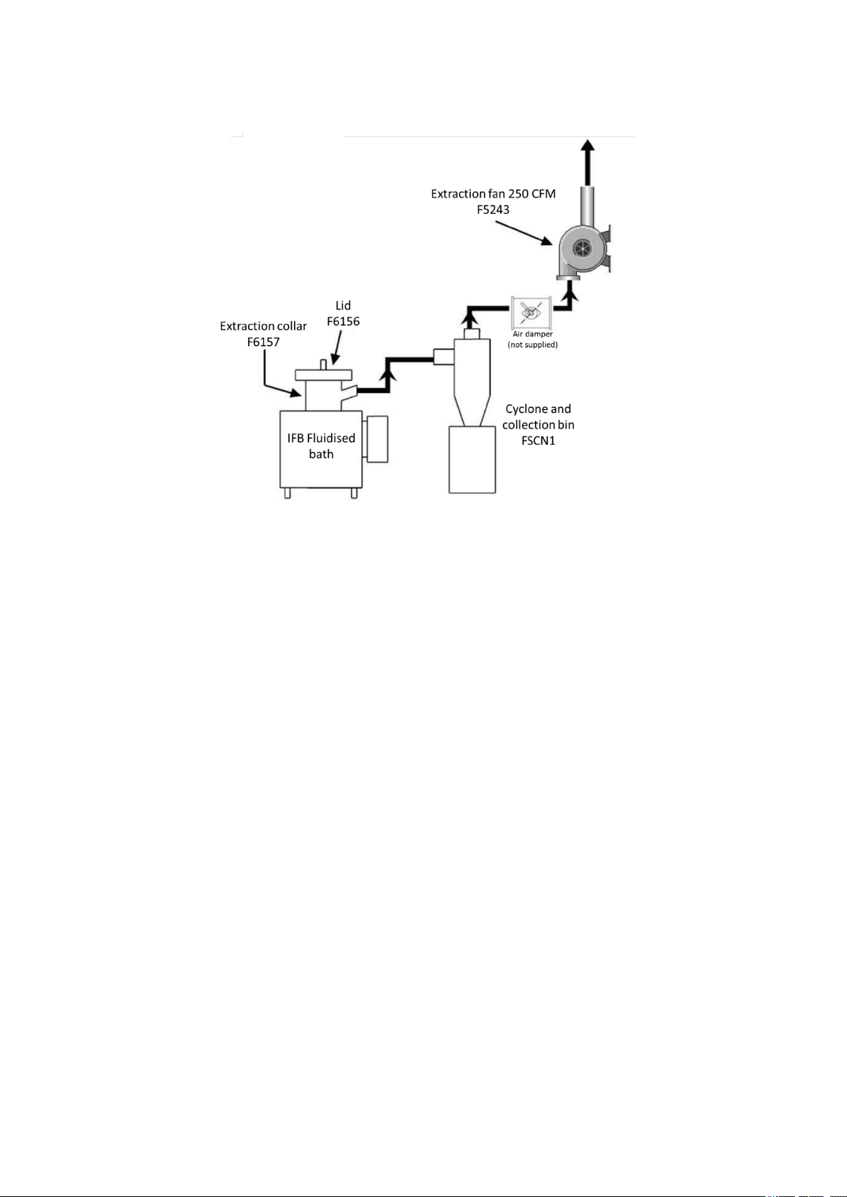
Figure 2: Schematic of IFB fluidised bath set up with cyclone and basic exhaust extraction
system.
SET-UP
The extraction collar, cyclone and extraction fan should be interconnected using appropriate 100mm (4”)
ducting. The
sieved and reused. An air damper should be positioned in the ducting between the cyclone and extraction
fan to control fume extraction and pull fumes away from the bath into the exhaust system. If the damper
is open too much it would create a negative pressure in the bath working area resulting in significant heat
and sand loss. A dilution tee (not shown) may also be included in the ductwork between the fluidised bath
and cyclone to dilute effluent gasses.
POWER
The IFB-51 and IFB-52 require a power supply of 230V, 50/60Hz, single phase. A 208V supply is insufficient
and should be boosted to 230V with a suitable boost transformer.
AIR
The compressed air supply to the bath must be clean, dry and free from oil. The pressure delivered to be
bath should be 30 psi (207 kPa) and capable of delivering 5 cubic feet/minute (CFM) (142 litres/min).
MECHANICAL
The unit should be mounted on a firm level surface. It is important to ensure that the bath is level, otherwise
it will fluidise incorrectly. This will lead to the formation of large temperature gradients across the bath
which results in premature heater failure and possible damage to the porous plate and inner container
assemblies.
1. Mount the fl
2. Connect a 30 psi air supply to the compressed air inlet on the rear of the control panel. The tubing and
any fittings should not be less than 13mm (1/2”) ID at any one point or bath performance may be
reduced.
3. Wire up the bath to a 220 to 240V single phase power supply. See section ELECTRICAL INSTALLATION.
4. Fill the bath with aluminium oxide to within 80 to 100mm (3 or 4 inches) of the top.
purpose of the cyclone is to recover any aluminium oxide pulled out of the bath which can be
uidised bath in the position where it is to be used on a dry, level surface.
Page 20

5. Place the ext
20
6. Install and connect any associated fume treatment equipment with appropriate ducting and connect
to the fluidised bath extraction collar. See figure 2 above and section FUME CLEANING.
raction collar (if used) into the bath.
OPERATION
START-UP
1. Check that the unit has been set up as described in the previous section and that required services are
available.
2. Check that aluminium oxide level is correct and adjust if necessary. Never add new, cold aluminium
oxide (which may contain moisture) to a hot bath. Should the fluidised bath be stored for long periods
of time under damp or humid conditions, moisture may be absorbed by the aluminium oxide which is
hydroscopic. To avoid violent fluidisation which occurs when damp aluminium oxide is heated above
100°C, operate the bath for a period of approximately 8 hours at 90°C prior to operation at elevated
temperatures.
3. Turn on power and air to the unit. Following the instructions displayed on the label on the unit, set the
air flow to 4 CFM when at ambient temperature. When fluidised and bubbling make sure the
aluminium oxide level is still within 80-100mm of the top.
4. Place the extraction collar (if purchased) into the bath and place the lid on.
AIR ADJUSTMENT
5. Important: as the bath heats up you will need to adjust the airflow settings based on the front label
chart or the heat up time will greatly increase. See Table 1 below. The reverse needs to happen when
cooling down.
Indicated bath temperature
Temperature (°C) Temperature (°F)
Ambient to 50 Ambient to 122 4.0
50 to 100 122 to 212 3.5
100 to 200 212 to 392 3.0
200 to 300 392 to 572 2.2
300 to 400 572 to 752 1.9
400 to 500 752 to 932 1.7
500 to 600 932 to 1112 1.4
Table 1: Ai
r flow rate settings at indicated bath temperatures.
Flow rate (CFM)
BATH TEMPERATURE
6. Set the controller to the required operating temperature. Once the controller has reached the set point,
allow 1 hour for the bath to fully stabilize before attempting to use it.
An initial temperature drop or quenching of the bath can occur after inserting a workpiece to be cleaned.
This temperature drop depends on the size of the immersed object, but is generally in the order of 25°C
(77°F). Carbon is burned to carbon dioxide quickly above 400°C (752°F). It may be found desirable to preheat the bath to as high as 550°C (1020°F) to obtain quick results, but caution should be exercised not to
damage tools by overheating.
EXTRACTION AIR SETUP
If you use an exhaust hood for ventilation, please ignore this section.
Page 21
7. Make sure
21
FUME CLEANING).
8. With the exhaust fan on, close the damper so there is no extraction to the bath.
9. Place parts to be cleaned in the basket and lower into the bath. Place the lid on the bath.
10. When smoke and fumes start to come up and around the lid, slowly open the damper just to the point
where they are pulled back into the bath and no longer entering the room, then stop adjusting. This
setting will give good results with minimal heat and sand loss.
11. With your first tool cleaning, start with a smaller number of tools and at a lower temperature. Adjust
the bath set temperature and the number of tools cleaned based on your results and the amount of
time required. It is always a good idea to clean at the lowest possible temperature.
12. After repeated tool cleanings heavier clumps and larger particles should be sieved from the aluminium
oxide.
13. In time, the aluminium oxide may become dense and fluidise poorly at which point it should be
replaced.
the exhaust system is plumbed according to our recommendation (see Figure 2 and section
SHUT-DOWN
14. The bath air supply and power can be turned off after the temperature has cooled to 200°C/400°F.
15. Alternatively, if used daily, reduce the overnight temperature to 300°C for quicker start up.
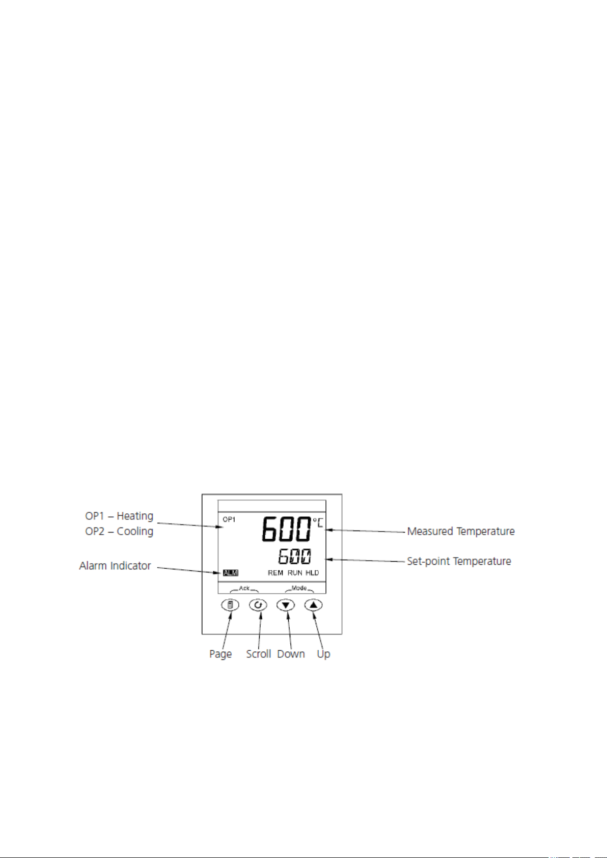
PID TEMPERATURE CONTROLLER
The control parameters in the PID temperature controller have been optimized by the factory during
manufacture to give the best results for most applications. Per the image below use the “scroll” button to
navigate to the menu option UNITS for changing display from °C to °F and vice versa.
Two set points can be entered for future recall, press the “scroll” button to access SP1 and SP2. Set a
different set point in each of these. Then “Scroll” to SP.SEL to select either set point SP1 or SP2. The up/
down buttons are used to set the bath set point temperature. If an alarm indicates an overtemperature
condition or thermocouple failure the two buttons labelled as ACK need to be depressed together after
the alarm condition is corrected. If the alarm cannot be cleared please contact Cole-Parmer for support.
Figure 3
: Eurotherm 3216 temperature controller.
Page 22

THE CLEANING PROCESS
22
The cle
heat then degrades the plastic residue. Objects to be cleaned should be supported in a basket or suitable
holder for ease of handling and lowered into the fluidised bed. To avoid physical damage and local
overheating, it is important to ensure that any items placed in the bed are supported and not allowed to
rest either on the porous plate at the bottom of the bed or against the wall of the inner container.
The bath should be operated generally in the temperature range of 450°C to 500°C, depending on the
polymer to be removed. The process time depends upon the thermal mass of the object, the amount and
type of polymer to be removed. During the first two thirds of the process time the polymer is reduced to a
tar mix, in this phase all the initially combustible products of the polymer are emitted from the fluidised
bath in the form of fumes that must be extracted and treated by suitable fume handling equipment. During
the last third of the process time, the polymer is reduced to carbon which either burns away or remains
loosely bound to the object being cleaned.
Any carbon or incombustible filler that remains on the processed item can be removed by a secondary
cleaning operation, either by brushing or some form of water wash.
It is important to ensure that the items being processed do not exceed the maximum loading capacity (see
section TECHNICAL SPECIFICATION) and that they are loaded into the fluidised bath in such a way that the
fluidisation is not impeded.
THE PROCESS RELIES UPON GOOD FLUIDISATION TO ENSURE GOOD HEAT TRANSFER; OVERLOADING OR
INCORRECT LOADING OF THE BATH WILL RESULT IN EXTENDED CYCLE TIMES GIVING INFERIOR RESULTS.
LOCAL OVERHEATING MAY ALSO OCCUR, GIVING RISE TO PREMATURE HEATER FAILURE AND POSSIBLE
DISTORTION OF THE INNER CONTAINER.
aning process relies on heat being transferred from the fluidised bed to the immersed tools, the
The aluminium oxide fluidising medium does not degrade but will need to be replenished due to loss from
spillage or entrainment in the exhaust (from where it may be recovered by the cyclone trap).
All articles should be completely cleaned and removed from the bed before shut down. Corrosion of
processed parts could be seriously increased if they are left immersed overnight. Furthermore, residual
polymer, instead of being burned off in a fluidised state, could percolate down through a static bed and
settle on the porous plate to cause a blockage and result in poor fluidisation. In the case of PVC, chlorinated
hydrocarbons remain in the fluidised bath after burn off which dictates special maintenance procedures.
See section SPECIAL MAINTENANCE PROCEDURES WHEN BURNING OFF PVC AND OTHER HALOGENATED
POLYMERS.
When parts are removed from the bed they should be allowed to cool in air and, whilst still warm, treated
to prevent rusting.
It should be noted that some plastics and, in particular, paints contain fillers. These fillers are usually
inorganic materials and will not therefore burn when put into a fluidised bath, with the result that the
material falls away from the article being cleaned and is retained in the bath, either on the surface or at
the base of the bath, depending upon the density of the material involved. If this happens it is
recommended that the bath be checked and cleaned at least once a week or more frequently if the bath
is used continuously.
Table 2 details recommended operating temperatures for particular polymers. The temperatures quoted
should be used as an initial guide. The ideal operating temperature will vary depending on the size of the
components being cleaned and the amount of material being removed. In general temperatures below
400°C should be avoided to obviate the danger of the polymer melting and sinking to the bottom of the
bath where it may block the porous plate. With some large objects, it may be desirable to preheat the bath
to well above the operating temperature so that the polymer temperature rapidly moves through the
melting phase to the burning condition.
Page 23

Excessive
23
bath and may result in the formation of condensed fumes within the extraction system.
operating temperatures should be avoided as they increase the fume concentration above the
Material Burn-off temperature (°C)
Nylon 450
Paint 475-575
Polythene 450-500
Polypropylene 425-500
PTFE 500
PVC 450-500
Silicone rubber 550
Ethylene methacrylic 450-480
Polyurethane 440-450
Rubber de-bonding 350 (de-bonding)
Polycarbonate 400-425
Polystyrene 450
Organic matter oil/grease 450-500
High density polythene 450
Polyesters 450
Fluoropolymers 500
Styrene 450
Table 2: Rec
CAUTION
Car
e should be taken when handling hot parts which have been removed from a fluidised bath. We
recommend that protective clothing (safety glasses, etc.) be worn when working with fluidised baths and
that the installation and maintenance procedures outlined in this booklet be followed explicitly.
ommended operating temperatures for various polymers.
FUME IGNITION
Spontaneous ignition may occur above the surface of the fluidised bath or within the exhaust ductwork if
the fume concentration exceeds the lower explosive limit.
The fume concentration is dependent upon the rate of fume production in the fluidised bath and the level
of dilution achieved by entraining air from above the bath or through the dilution tee.
The rate of fume production is dependent upon the type and amount of material being treated and the
temperature of the bath.
To ensure that the concentration of inflammable fumes is below the lower explosive limit, ensure that the
amount of combustible material immersed in the bath at any one time is within the design capacity of the
extraction system.
Ensure that the temperature of the bath is at minimum level to which satisfactory results can be achieved.
Increased working temperatures result in increased fume concentration. By way of example, an extraction
Page 24

3
24
rate of 2m
limit when thermally decomposing 1kg/hr of polythene at 450°C.
To safeguard the fluidised bath from damage, two safety features are included in the control console: an
adjustable over temperature cut-out which guards against controller failure, and an air pressure switch
which inhibits operation if the compressed air supply to the fluidised bath fails. Both devices isolate the
electrical supply to the heater elements and illuminate the cut-out indicator in a fault condition. The over
temperature cut-out is factory pre-set at 630°C. Under no circumstances should this setting be increased,
but lower limits may be set to safeguard particular processes in the fluidised bath.
/min is required to ensure that the fume concentration is below 25% of the lower explosive
FUME EXTRACTION AND CLEANING
When used for processing items which may emit toxic or inflammable fumes, it is essential that an adequate
fume extraction system be installed. A typical schematic diagram of a full fume extraction system is shown
in Figure 4. The system consists of the following components: -
Ductwork to connect the fluidised bath extract duct via the various fume treatment equipment to the input
of the fume extraction fan. The ductwork should include an air dilution tee, positioned as close as possible
to the fluidised bath. The dilution tee enables the fumes within the system to be diluted with air. The
ductwork should also include a damper valve which is normally positioned adjacent to the extraction fan.
This valve allows the extraction velocity to be reduced. In general, the ductwork may be manufactured out
of galvanised mild steel; however, in installations where PVC or other halogenated polymers are being
processed, it is recommended that stainless steel ducting is used. The ductwork should be as short as
possible and contain the minimum number of bends and horizontal runs to reduce the possibility of a
blockage.
A cyclone separator should be mounted directly after the dilution tee. The cyclone removes any fluidised
medium that may be present in the extracted fumes. The fluidised medium is collected in the cyclone
collection bin from where it may be returned to the fluidised bath. In applications where the components
being cleaned are contaminated by polymers which contain inorganic pigments or fillers such as titanium
oxide, of a particle size less than 0.005mm diameter which will not be retained by the cyclone, it is
recommended that a filtration system be fitted after the cyclone.
In applications where the materials being treated produce acidic vapours during thermal decomposition, it
is recommended that a fume scrubber be utilised to ensure that the final fume emission from the plant
conforms with local regulations. A caustic dosing system may also be required to ensure that the scrubbing
liquid is maintained at an acceptable pH level.
An extraction fan is required in all applications to provide the motive force for the exhaust.
In applications where it is not permissible to emit visible smoke from the plant or where local regulations
specify the maximum fume concentrations that may be emitted from an exhaust stack, an afterburner may
be required. The afterburner heats the fumes to a point where thermal incineration eliminates the visible
content of the fumes while reducing the fume concentration.
Finally, an exhaust stack is required to direct the treated fumes away from the working environment. The
exhaust stack will generally be manufactured out of the same materials as the ductwork system. However,
in installations where an afterburner is fitted, the exhaust stack should be manufactured out of insulated
stainless steel.
The exact combination of fume treatment components required depends upon the application and local
conditions.
Page 25

Figure 4: Full extraction system required for burn-off of toxic fumes and PVC. *Items not supplied
25
by Techne.
OPERATOR MAINTENANCE
The aluminium oxide fluidising medium, not being degradable, will only require replacement when losses
occur due to attrition, spillage or contamination with inert pigments, filler or acidic by-products from the
burn-off process. Note that the aluminium oxide pulled out of the bath through the exhaust duct can be
captured for reuse by the cyclone trap.
Should the fluidised bath be stored for long periods of time under damp or humid conditions, moisture
may be absorbed by the aluminium oxide which is hydroscopic. To avoid violent fluidisation which occurs
when damp aluminium oxide is heated above 100°C, operate the bath for a period of approximately 8
hours at 90°C prior to operation at elevated temperatures.
On at least daily intervals, the bed should be cleaned of floating residues by means of a wire mesh hand
scoop. This procedure removes carbon char which impairs fluidization and acts as an absorbent. More
importantly, it can also remove uncharred plastic and so reduce the quantity of fumes produced and the
time of processing.
The optional air-line filter into the bed is self-draining. However, it should be kept in good condition by
inspection at two week intervals and by cleaning the bowl and washing or replacing the filter element as
necessary. With exceptionally dirty or wet air supplies, this frequency may have to be increased. Free water
or water vapour in the air supply acts as a solvent to produce hydrochloric acid in the bed when PVC is
burned off. In addition, oil vapours in the air supply which reach the fluidising plate are carbonized within
the pores of the plate, quickly causing blockage and consequent poor fluidization, local overheating,
premature heater failure and possible distortion of the inner container.
Page 26

All artic
26
processed parts could be seriously increased if they are left immersed overnight. Furthermore, residual
plastic, instead of being burned off in a fluidised state, could percolate down through a static bed and
settle on the porous plate causing blockage and poor fluidization.
When parts are removed from the bed, they should be allowed to cool in the air and, while still warm,
wiped with on oily cloth to prevent rusting. If the bath is left unused for long periods of time, empty the
aluminium oxide and store it in a separate container. Keep the inside of the bath clean and dry.
The fume extraction system (if used) should be regularly maintained. The cyclone trap collection bin should
be emptied at the end of each day’s use; the collected fluidising medium being returned to the fluidised
bath. It is important to ensure that the air tight seal between the cyclone and collector bin is re-made.
les should be completely cleaned and removed from the bed before shut down. Corrosion of
SPECIAL MA
INTENANCE PROCEDURES WHEN BURNING OFF PVC OR
OTHER HALOGENATED POLYMERS
Burning off PVC (polyvinyl chloride) in a fluidised bath offers one of the most severe conditions of operation.
Hydrogen chloride (HCl) liberated on the breakdown of PVC is absorbed by the bed medium creating an
acidic environment within the bed. This happens especially when the bed also absorbs water from the
atmosphere or when the fluidising air is cold. HCl is extremely corrosive, especially when it is aerated and
wet. In addition, in water it produces chloride ions which, even in neutral or alkaline solutions, promote
corrosion and rusting in steel.
Consequently, fluidising beds used for burning off PVC require strict supervision to minimize corrosion of
the bed itself and of parts cleaned in it, especially if these are of un-coated steel. The purpose of most of
the recommended maintenance procedures is aimed at keeping the bed medium clean, free-flowing, free
of gums, acids, agglomerates, partly decomposed plastic, char and larger particles. These cleaning
processes have the additional benefit of ensuring good fluidization and thus good heat transfer throughout
the bed and through immersed parts. This, in turn, reduces burn-off time, uneven heating of parts and
thus distortion, increases heater life by eliminating localized hotspots and makes cleaning easier on a regular
basis.
The following instructions apply generally to halogenated polymers and specifically to PVC. They are aimed
at minimising corrosion of the bath and of immersed metals.
DAILY INTERVALS - at the end of each working day
1. Maintain the working temperature (about 400°C) for half an hour after the last processed batch, to
assist removal of corrosive acids from the bath.
2. If possible, maintain the temperature of the bath at about 100°C overnight and over weekends and
holidays to reduce absorption of water vapour into the batch. Overnight, the residual heat in the bath
will usually ensure this.
3. Scoop out charred plastic residues, clods of media and articles being processed.
WEEKLY INTERVALS - at the end of each working week and before prolonged shut-downs
1. Ensure compliance with daily instructions above.
2. Add about 50g (2oz) of powdered mild alkali to the bath and mix in well by maintaining fluidisation
for 5 minutes. Suitable alkalis are limestone, dolomite, hydrated or slaked lime, sodium bicarbonate,
sodium carbonate, magnesia. The addition of corrosive alkalis such as caustic soda (sodium hydroxide)
and quick lime (calcium oxide) should be avoided.
MONTHLY INTERVALS
1. Empty the bath and inspect it for signs of corrosion, especially pitted surfaces and flaking scale. The
inside should be wiped out with a rag wetted with 5% washing soda (sodium carbonate) solution.
Page 27

2. Screen the
27
scale, agglomerated medium, char, undegraded polymer and lost parts and helps maintain a good
quality of fluidisation.
HALF-YEARLY INTERVALS
1. The bath should be emptied, cleaned, inspected and the medium replaced by a fresh charge.
2. Alternatively, if the facilities are available, the medium may be thoroughly washed in several changes
of clean water, washed through a 70-mesh sieve, drained, dried and returned to the bath where drying
is completed by fluidisation and heating at 150°C, until the medium fluidises in the normal manner.
The washing procedure removes acidic residues and accumulated soluble salts and residues.
Symptoms of neglect should be dealt with immediately. These include: pitting of metallic surfaces,
formation of lumps of agglomerated medium, accumulation of polymer or polymer filler material,
indications of bad or uneven fluidisation, blockage of the fluidising plate and wetness or stickiness of the
medium.
medium through a 50 to 70 mesh sieve before returning it to the cleaned bath. This removes
FAULT FINDING
Any service or repair work should only be carried out by a trained electronic or electro mechanical
technicians. Untrained personnel should not attempt to dismantle this equipment.
If the heater indicator fails to go off, the unit fails to reach its operating temperature or heat up rate
decreases, check:
1. Fluidization – remove aluminium oxide from bath leaving approximately 50mm (2”) in the bottom. If
an area of one quarter or more is not bubbling, then most likely the porous plate is blocked and should
be replaced. Check that the porous plate is not blocked with plastic residue or other material.
2. Heater - Empty medium from the bed and disconnect the main supply. Turn the unit upside down and
check the resistance of the heater. If one or more heater windings are faulty, replace the heater.
Reassemble in the reverse order.
3. Thermocouple – check with an instrument that can measure and simulate thermocouple signals to
verify its operation.
4. Controller and/or SSR – the controller will output a DC signal to the SSR when heat is called for. If the
SSR is receiving a DC control signal but not passing power to the heaters, then it should be replaced.
Alternatively, a problem may exist with the controller. If the fluidization deteriorates, check the air filter
assembly for clogging of the filter element; if necessary, replace the element.
If the fault remains, run your bath at 600°C (1100°F) for a period of one hour to allow any accumulated
residue in the bath to burn off. If the fault persists, empty the medium from the bed, check the stainless
steel porous plate for damage due to clogging by plastic residue, distortion of the plate or corrosion.
Factory PID Parameters (For IFB51 S/N: 451 and higher, IFB52 S/N: 214 and higher)
Parameter IFB-51 IFB-52
Pb 15 12
Ti 450 480
Tg 75 80
1PLS 5.0 5.0
CBHI 20 20
CBLO 20 20
Page 28

SAFETY, REPAIR AND TECHNICAL SUPPORT
28
NOTE THAT THIS EQUIPMENT SHOULD ONLY BE DISMANTLED BY PROPERLY TRAINED PERSONNEL.
REMOVING THE CASE EXPOSES POTENTIALLY LETHAL MAINS VOLTAGE.
THERE ARE NO OPERATOR MAINTAINABLE PARTS WITHIN THE EQUIPMENT.
In the unlikely event that you experience any problems with your fluidised bath which cannot easily be
remedied, it may be necessary for your equipment to be sent back to our service department for
repair. In this case please contact the service department for all the required returns paperwork,
including the decontamination certificate, which must be included when you return the equipment.
Please also ensure you include a clear description of the fault. The decontamination certificate must be
completed to certify that the returned item is not contaminated with any harmful substance. Failure to
complete this will prevent the repair of your equipment.
Please return the unit in its original packing. Techne accept no responsibility for damage to units which are
not properly packed for shipping: if in doubt, contact your supplier. Clearly mark the package for the
attention of the Service Department and post to the following address:
Cole-Parmer Ltd
Beacon Road
Stone
Staffordshire
ST15 0SA
United Kingdom
Only spare parts supplied by the manufacturer or its agent should be used. Fitting of non-approved parts
may affect the performance of the safety features of the equipment. If in doubt, please contact Techne.
If you require further technical or application assistance, please contact Techne at:
E-mail: cptechsupport@coleparmer.com
Phone: +44 (0)1785 810433
WARRANTY
Techne warrants this equipment to be free from defects in material and workmanship, when used under
normal laboratory conditions, for a period of three (3) years. In the event of a justified claim, Techne will
replace any defective component or replace the unit free of charge.
This warranty does NOT apply if:
• Any repair has been made or attempted other than by the manufacturer or its agent.
• Any minor coating chips or scratches occur during normal use (i.e., wear and tear).
• Damage is caused by fire, accident, misuse, neglect, incorrect adjustment or repair, damage
caused by installation, adaptation, modification or fitting of non-approved parts.
Page 29

TECHNICAL SPECIFICATION
Temperature range
50°C to 600°C (122°F to 1112°F)
50°C to 600°C (122°F to 1112°F)
±1.0°C (20cm/8" immersion depth
with lid after 2 hours at set point)
±1.0°C (46cm/18" immersion depth
with lid after 2 hours at set point)
±10.0°C (20cm/8" immersion depth
with lid after 2 hours at set point)
±10.0°C (46cm/18" immersion
depth with lid after 2 hours at set
Type of control
3 term PID
3 term PID
Sensor type
K type thermocouple
K type thermocouple
Working diameter when
213mm (8.4”)
213mm (8.4”)
Depth
405mm (16”)
762mm (30”)
207 to 1034 kPa (30 to 150 psi)
clean, dry and oil-free
207 to 1034 kPa (30 to 150 psi)
clean, dry and oil-free
Air Consumption at
Ambient (max)
450°C
600°C
Nominal heater power
4kW
6kW
Exhaust fan requirements
7125 litres/min (250 CFM)
7125 litres/min (250 CFM)
Net weight
60kg (132lb)
84kg (185lb)
Gross weight incl.
Overall size W x D x H
29
Specifications IFB-51 IFB-52
Stability at 450°C
Display accuracy
Temperature display °C or °F °C or °F
Internal diameter 255mm (10.1”) 255mm (10.1”)
Working depth when 305mm (12”) 660mm (26”)
Load Capacity (1/3 of
volume)
Air pressure
Air Consumption at 48 litres/min 48 litres/min
Fluidised medium
Heat up time 20°C to
Heat up time 20°C to
Electrical supply 230V, 50/60Hz, single-phase 230V, 50/60Hz, single-phase
5 litres 12 litres
115 litres/min 115 litres/min
40kg (88lb) aluminium oxide
(Alundum), 120 mesh, part code
Brown/ALO
105 minutes 210 minutes
150 minutes 300 minutes
73kg (160lb) aluminium oxide
(Alundum), 120 mesh, pa
Brown/ALO
rt code
aluminium oxide
100kg (220lb) 156kg (344lb)
521 x 521 x 686 609 x 533 x 1041
Page 30

REPLACEMENT PARTS
30
The following parts may be purchased if replacements are required:
Part number Item description
7001560 25A fuse for IFB-51
7001665 30A fuse for IFB-52
Brown/ALO
25kg alundum, brown aluminium oxide
ACCESSORIES
The following accessories are available for use with the IFB-51 and IFB-52.
Sample basket
The steel mesh sample basket safely holds samples away from the heating elements of the fluidised bath
and assists retrieval of items from the bath.
Product code Item description
FA624 Basket for IFB-51 (standard basket)
FA625 Basket for IFB-51 (deep basket, used with extraction collar)
7031658 Basket for IFB-52 (standard basket)
7031659 Basket for IFB-52 (deep basket, used with extraction collar)
Extraction collar
The extraction collar is used with the deep baskets and allows ducting to be connected for fume extraction
away from the bath.
Product code Item description
F6157 Extraction collar for IFB-51 and IFB-52
Lid
Lids are a vital part of the IFB process to contain the aluminium oxide and retain heat. They are designed
to allow airflow into the top of the bath and allow clean air to be drawn into the bath and through the
exhaust duct when connected to an extraction system. The IFB-51 and IFB-52 have an insulated lid.
Product code Item description
F6156 Lid for IFB-51 and IFB-52
Air pressure regulator and filter
Techne can supply a filter/regulator assembly for compressed air which is not moisture or oil-free.
Product code
F5915
CN-100 Cyclone and Collection bin
An efficient wall mounted unit which can extract all the aluminium oxide carried over into the IFB exhaust
system when the extraction fan is in operation. The cyclone collection bin allows escaped aluminium oxide
to be collected and re-used. An extraction fan and cyclone are recommended unless a suitable extraction
hood or fume extraction system is already in place.
Product code Item description
FSCN1 CN-100 Cyclone and collection bin for IFB-51 and IFB-52
Extraction Fan
Powerful 380/415V, 3 phase fan delivering an extraction rate of 250CFM (425m³/hr).
Item Description
Filter Pressure regulator for IFB-51 and IFB-52
Product code
F5243
F5243-60Hz
Item description
Fan 250CFM, 380 / 415V, 3 Phase, 50Hz
Fan 250CFM, 380 / 415V, 3 Phase, 60Hz
Page 31

This product meets the applicable
31
31
harmonised standards for radio frequency
interference and may be expected not to
interfere with, or be affected by, other equipment with
similar qualifications. We cannot be sure that other
equipment used in its vicinity will meet these standards
Declaration of Conformity is also available to view online at www.techne.com
and so we cannot guarantee that interference will not
occur in practice. Where there is a possibility that injury,
damage or loss might occur if equipment malfunctions
due to radio frequency interference, or for general
advice before use, contact the manufacturer.
Page 32

Cole-Parmer Ltd.
Beacon Road,
Stone,
Staffordshire,
ST15 0SA,
United Kingdom
Tel: +44 (0)1785 812121
Email: cpinfo@coleparmer.com
Web: www.techne.com
 Loading...