

Page 1
Network Camera User’s Manual
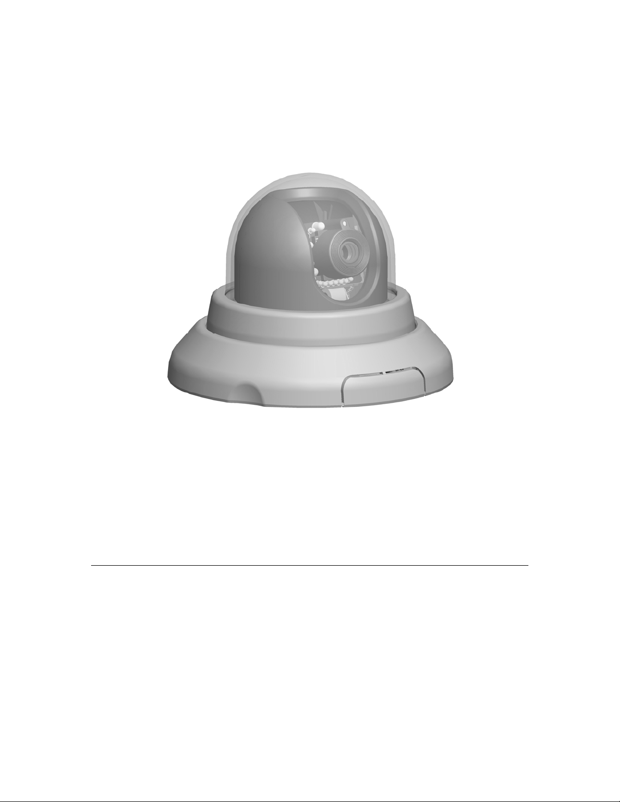
H.264 Pan/Tilt Dome Night Vision IP
Camera
User’s manual
Version 0.1
1/62
Page 2

Network Camera User’s Manual
Table of Contents
Overview...............................................................................................................3
Package Contents.................................................................................................4
Connections..........................................................................................................5
Hardware description.....................................................................................5
Connections..........................................................................................................7
Connect to the Network Camera.........................................................................11
Install the IP Finder program........................................................................ 11
Bonjour program ..........................................................................................21
ip-discovery.com(Free DDNS service) .........................................................22
Initial Access to the Network Camera.................................................................25
Primary user’s capability.....................................................................................27
Main Screen with Camera View...................................................................27
Client Setting ...............................................................................................30
Definitions in Configuration.................................................................................32
System parameters.............................................................................................32
Security...............................................................................................................34
Network...............................................................................................................36
Access list...........................................................................................................39
Audio and Video setting......................................................................................40
Video record .......................................................................................................42
Stream................................................................................................................44
Camera control...................................................................................................46
Application ..........................................................................................................48
Storage...............................................................................................................51
Syslog.................................................................................................................52
Status and Parameters.......................................................................................53
Maintenance .......................................................................................................54
Appendix.............................................................................................................56
A. Troubleshooting & Frequently Asked Questions......................................56
B. Technical specifications...........................................................................62
2/62
Page 3

Network Camera User’s Manual
H.264 Pan/Tilt Dome Night Vision IP Camera
Overview
Law in your country may prohibit the use of surveillance devices. The Network Camera
is not only a high-performance web-ready camera but also can be part of a flexible
surveillance system. It is the user’s responsibility to ensure that the operation of such
devices is legal before installing this unit for its intended use.
It is important to first verify that all contents received are complete according to the list in
the "Package Contents" chapter. Take notice of the warnings in “Quick installation guide”
before the Network Camera is installed, then carefully read and follow the instructions in
the “Installation” chapter to avoid damages due to faulty assembly and installation. This
also ensures the product is used properly as intended.
The Network Camera is accessible via the LAN or Internet connection. Connect your
Network Camera directly to a computer network or DSL modem, and with a standard
Web browser you get instant, on demand video streams. Within minutes you can set up
the Network Camera to capture a video sequence to a PC. Live video image can be
uploaded to a website for the world to see or made available only to select users on the
network.
The Network Camera is a network device and its use should be straightforward for those
who have basic network knowledge.
The Network Camera is designed for various applications including video sharing,
general security/surveillance, etc. The “How to Use” chapter suggests ways to best
utilize the Network Camera and ensure proper operations.
Minimum System Requirement
H.264 Pan/Tilt Dome Night vision IP Camera
Network Environment
LAN 10/100M Ethernet
Monitoring System Recommended for Internet Explorer
System Hardware Basic requirements
· CPU: Intel® Celeron® Dual-Core @2.70GHz or above
· Memory Size: 2 GB or above Recommended
· VGA card resolution: 1024 x 768 or above
System Requirement for Viewer & Recorder Application
Support OS XP, Windows 7
System Hardware 1-4 cameras surveillance application
· CPU: Intel® Celeron® Dual-Core @ 2.70GHz or above
· Memory Size: 2 GB or above
· VGA card resolution: 1024 x 768 or above
3/62
Page 4
Network Camera User’s Manual
Package Contents
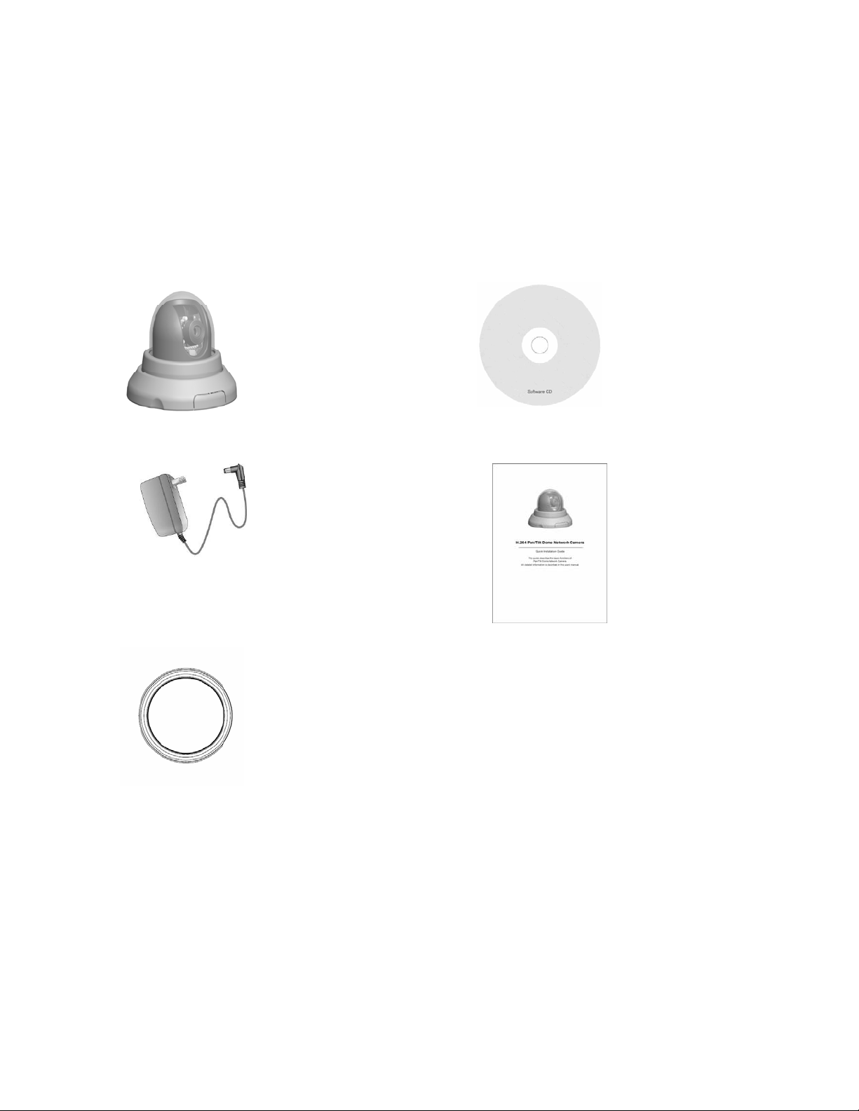
If any of the above items are missing, please contact your dealer immediately.
Network Camera (Wired)
Power adapter
Bracket
Software CD
Quick installation guide
Note: Using a power supply with a different voltage than the one included with the
Network Camera will cause damage and void the warranty for this product.
4/62
Page 5

Network Camera User’s Manual
Connections
Hardware description
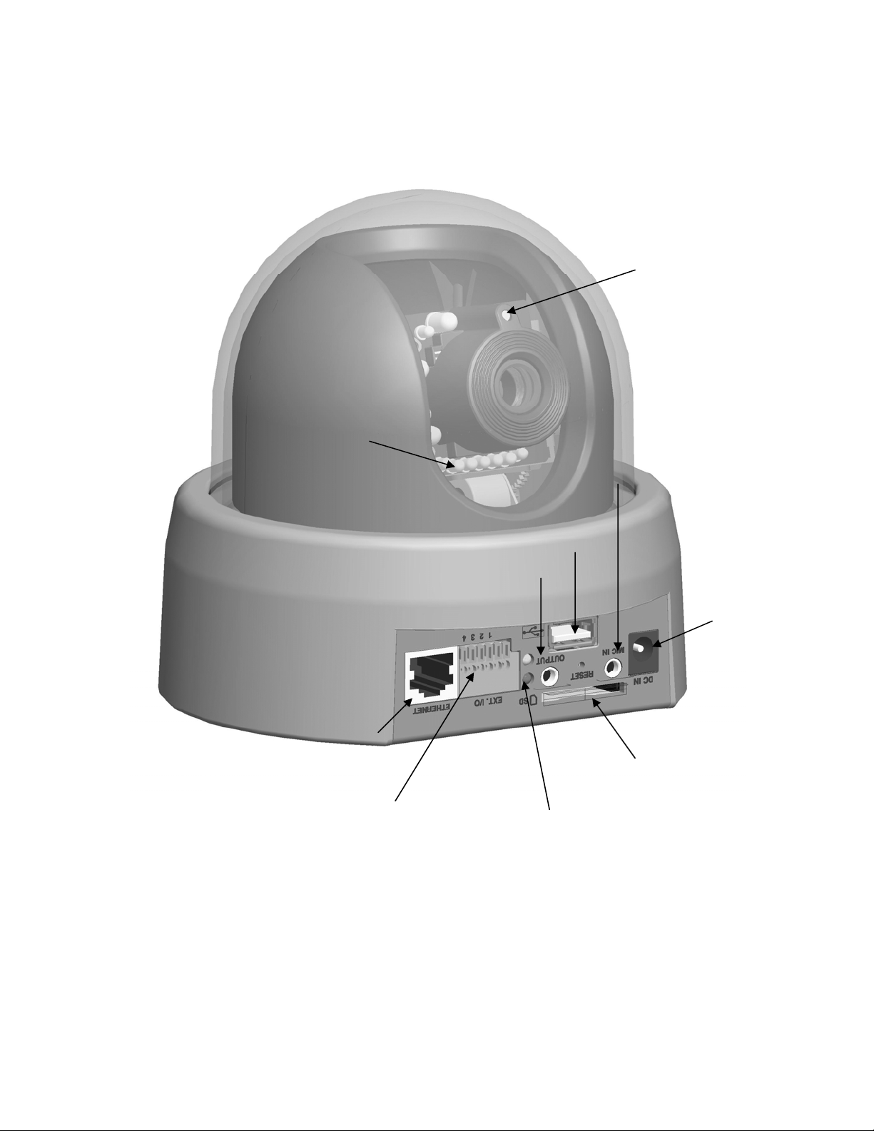
1. DC Power Jack
The DC power input jack is located on the rear of Network Camera’s. The input power is
12VDC. Note that supply the power to the Network Camera with standard power adapter
included in package. Otherwise, the improper power adapter may damage the unit and
result in danger.
2. LAN Socket
Beside the DC power Jack, the LAN socket is an RJ-45 connector for connections to
10Base-T or 100Base-TX Fast Ethernet cabling. Please use Category 5 “straight
through” cable to connect the Network Camera to an Ethernet network switch or hub.
3. Indicating LEDs
Red LED indicates power, red LED will turn on always after plug-in power.
Green LED indicates networking, green LED will blink every second after getting IP
address.
Upon powering up, two of front LEDs will become lighted then the camera will do
self-rotation. During the self-rotation, red LED will be on and the network camera is
standby for getting IP address.
4. Infrared LEDs and Light sensor
There are twelve Infrared (IR) LEDs and a light sensor in front of the head of camera for
night vision purpose. The IR LEDs will auto or manual turn on when the camera is in the
dark environment.
5. Factory Default Reset
This button is hidden in the pinhole under then Network Camera’s bottom. Please refer
to the Appendix A in this manual for more information.
6.SD Card slot and USB socket
The built-in SD/SDHC card slot offers a convenient and portable storage
(snapshots and video clips) option to prevent data loss in case of network
disconnection.
7.Microphone in and Audio out
The Network Camera supports two way audio communication so that operators can
transmit and receive audio simultaneously. By using the Network Camera’s built-in or
external microphone and an external speaker, you can communicate with people around
the Network Camera.
8.General I/O Terminal Black
This Network Camera provides a general I/O terminal block which is used to
connect external input / output devices.
5/62
Page 6
Network Camera User’s Manual
◎ Panel
Infrared LEDs
Light sensor
General I/O terminal block
USB Socket
Audio Jack
Indicating LEDs
6/62
Page 7
Network Camera User’s Manual
Connections
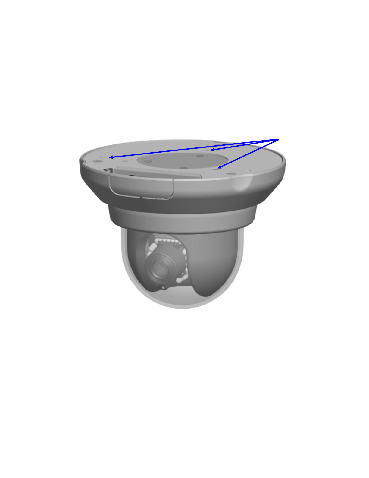
1. Attach the Network Camera with the included stand
2. Place the Camera on the table or fix it onto ceiling or wall
Use screws to fix the Network Camera onto the ceiling or wall. You could also put the
Network Camera on the table directly.
Fixed it by
Screws
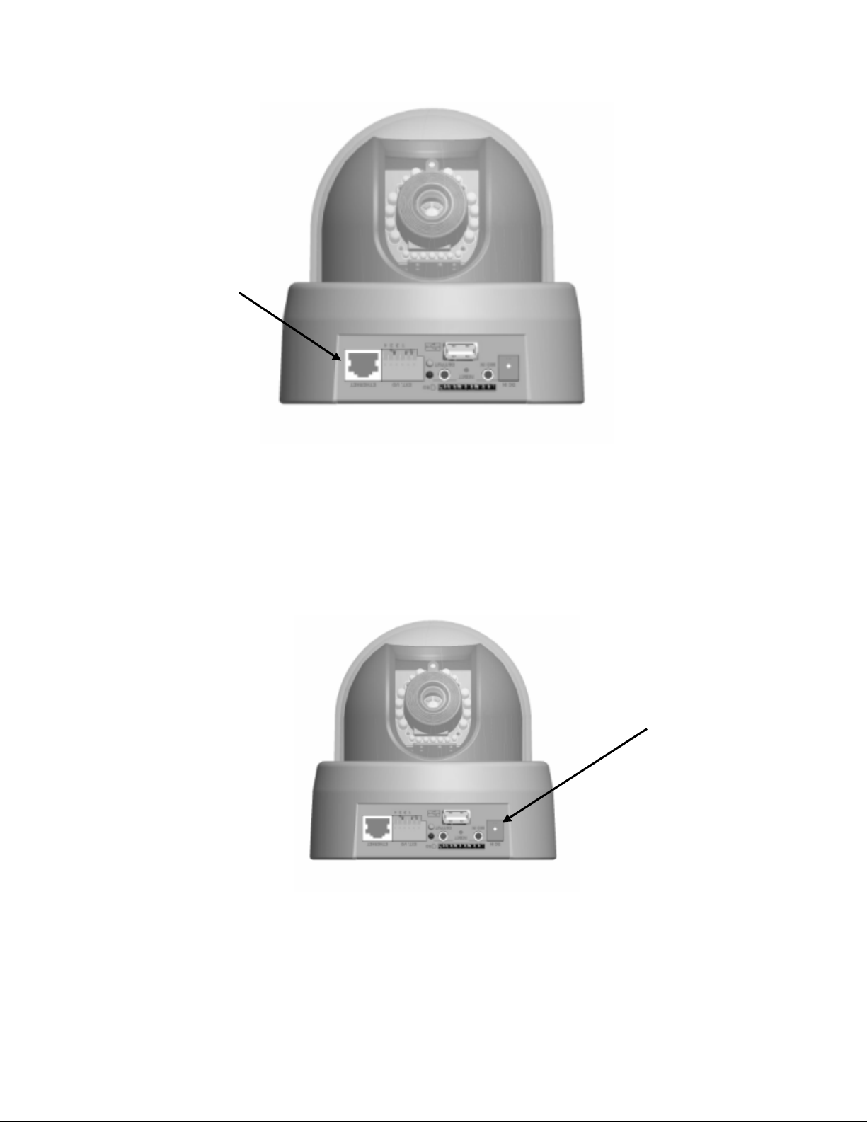
3. Plug a RJ-45 Ethernet cable into the Network Camera
Connect an Ethernet cable to the LAN socket located on the rear of Network Camera’s
and attach it to the network.
7/62
Page 8
Network Camera User’s Manual
Ethernet
Cable Socket
4. Connect the external power supply to Network Camera
Connect the attached power adapter to the DC power jack of the Network Camera. Note:
Use the power adapter, 12VDC, included in the package and connect it to wall outlet for
AC power.
Power
Socket
Once you have installed the Network Camera well and powered on, the camera
will do self-rotation and then the red LED will turn on and green LED will flash
every second. It means that the system is booting
8/62
Page 9
Network Camera User’s Manual
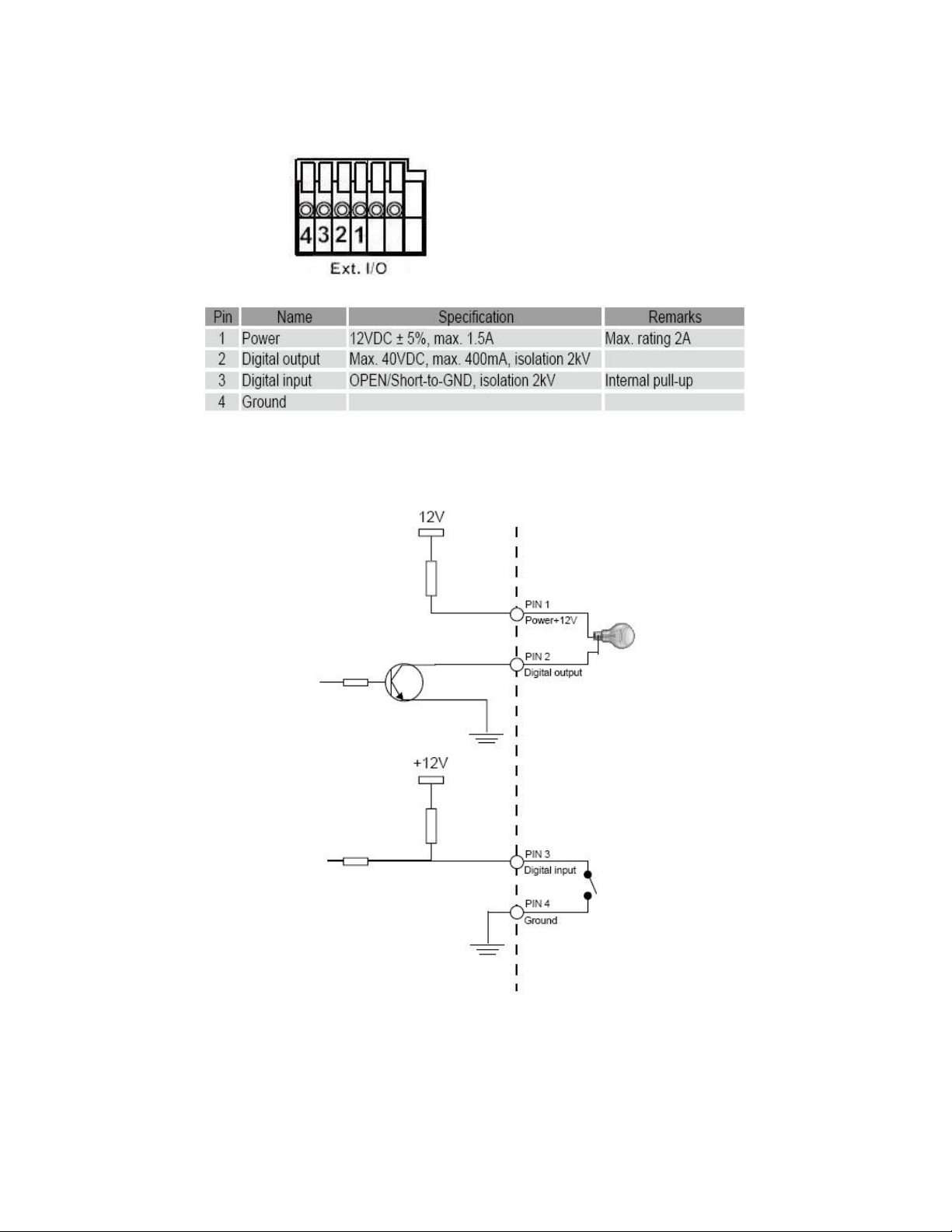
5. General I/O Terminal Block
1: Power
2: Digital output
3. Digital input
4. Ground
If you have external devices such as sensors and alarms make connection from
I/O terminal block.
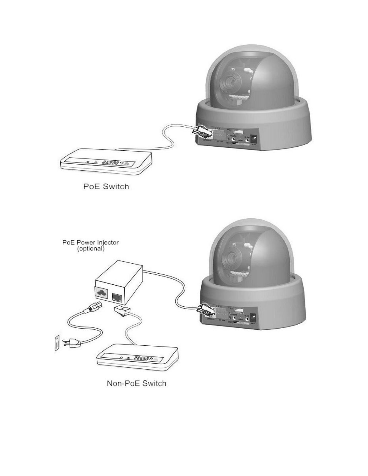
6. Set up the Network Camera through Power over Ethernet (PoE)
a. Using a PoE-enabled switch
The Network Camera is PoE-compliant, allowing transmission of power and
data via a single Ethernet cable. Follow the below illustration to connect the
Network Camera to a PoE-enabled switch via Ethernet cable.
9/62
Page 10
Network Camera User’s Manual
b. Using a non-PoE switch
If your switch does not support PoE, use a PoE power injector(optional) to
connect between the Network Camera and a non-PoE switch.
10/62
Page 11
Network Camera User’s Manual
Connect to the Network Camera
Install the IP Finder program
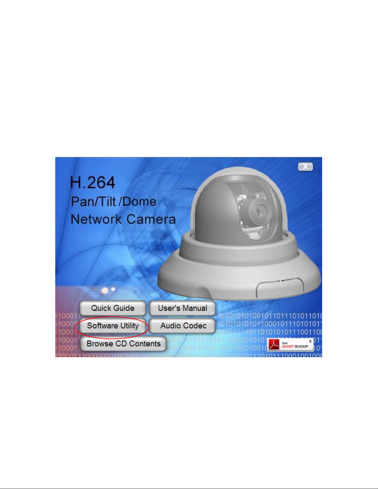
When you installed your Network camera on your LAN environment, you may install “IP
Finder” to discover Network camera’s IP address. The Administrator must place the
product software CD into the CD-ROM drive of the PC running in Microsoft Windows. An
auto-run program will pop up (If the program is not on auto-run, go to the root directory
of the software CD and click on “autorun.exe”).
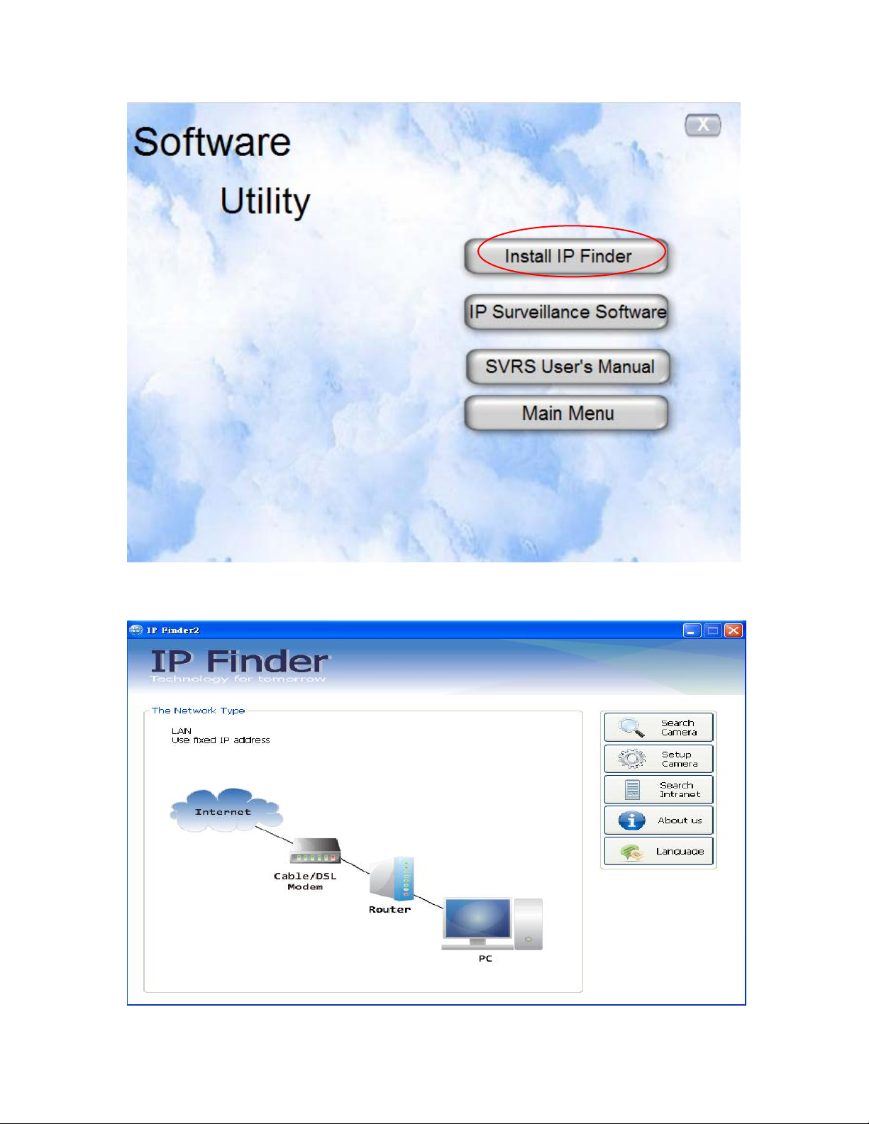
Click on “Software Utility” item, after the window contents changed, click on “Install IP
Finder2” to run “IP Finder2” program.
11/62
Page 12
Network Camera User’s Manual
“IP Finder2” is used to search the IP address of Network Cameras or Video
servers on a LAN. After searching, Video Servers or Network Cameras will be
located by the IP Finder.
12/62
Page 13
Network Camera User’s Manual
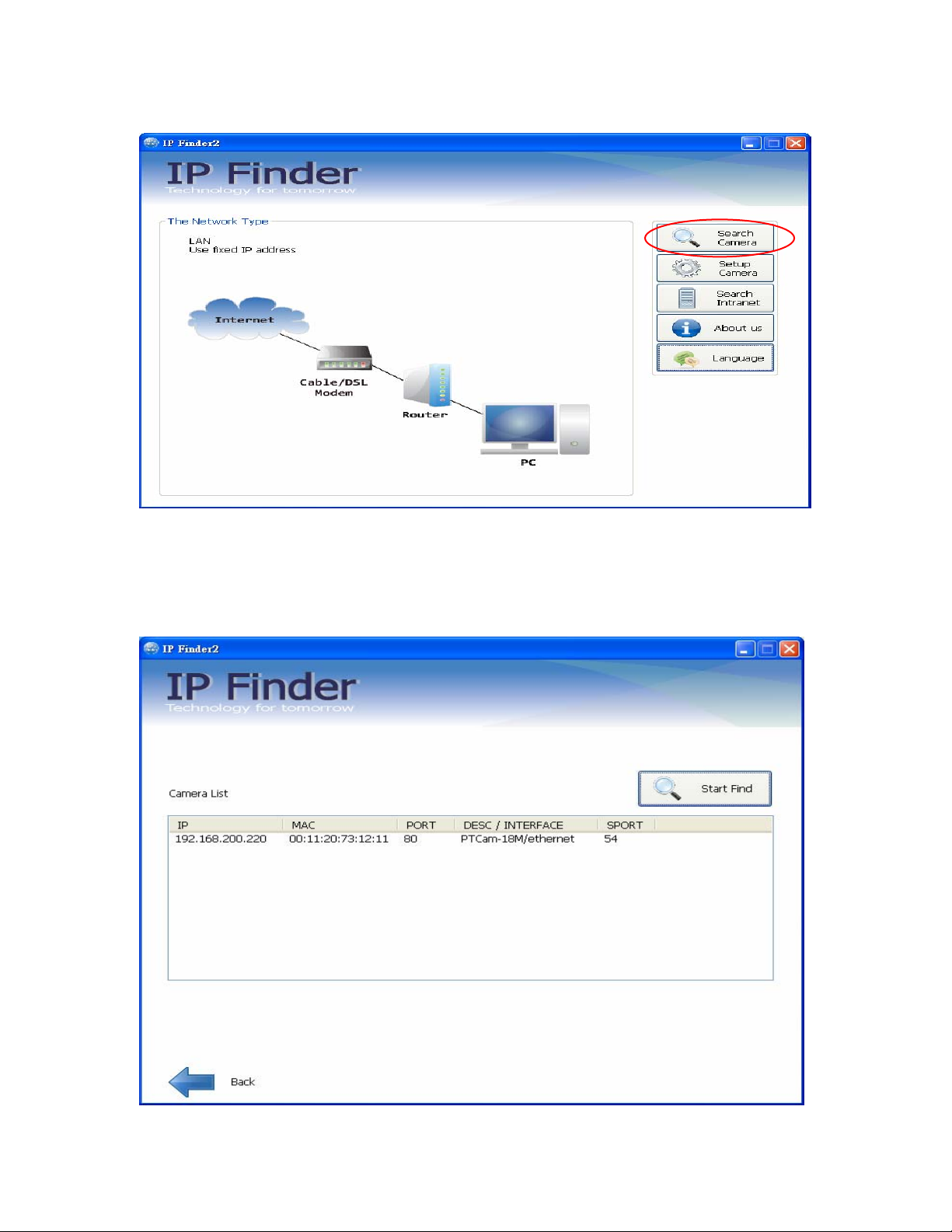
Search Camera
Click search Camera button, The program will search for all family network
devices on the same LAN. After searching, the main installer window will pop up.
Click on the MAC and model name which matches the product label on your
device to connect to the Network Camera via Internet Explorer.
13/62
Page 14
Network Camera User’s Manual
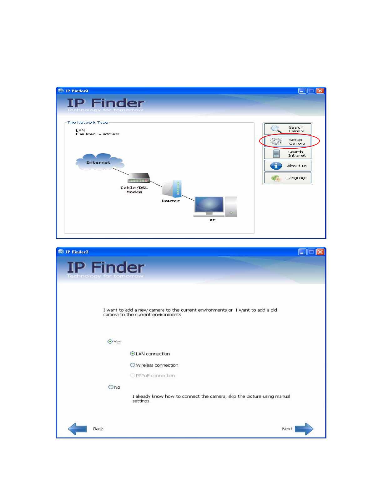
Setup Camera
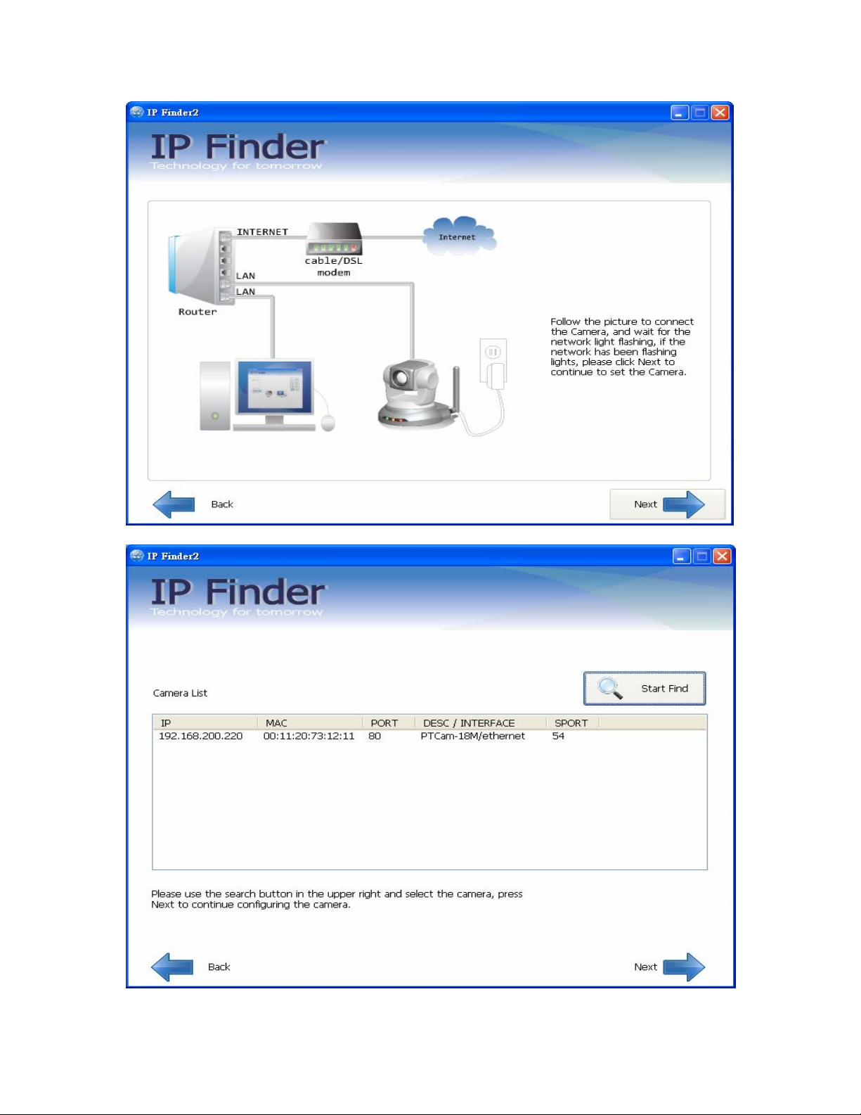
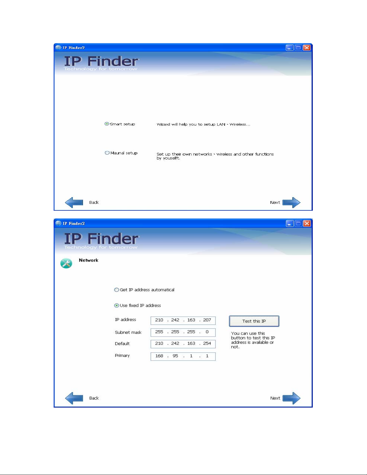
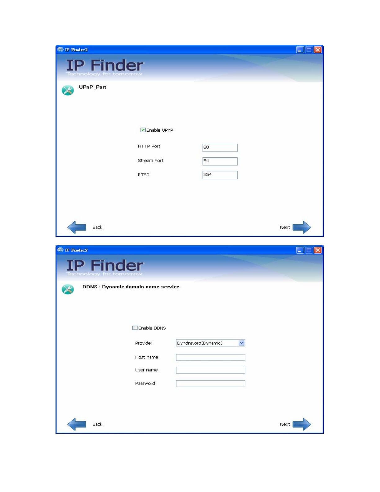
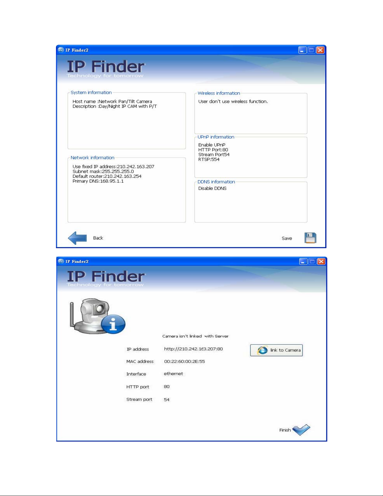
Auto Install Wizard will be started and that it can auto guide through the
installation process. Press the “Next” button execute next process. For more
information, please refer to the Network section on page 34.
14/62
Page 15
Network Camera User’s Manual
15/62
Page 16
Network Camera User’s Manual
16/62
Page 17
Network Camera User’s Manual
17/62
Page 18
Network Camera User’s Manual
18/62
Page 19
Network Camera User’s Manual
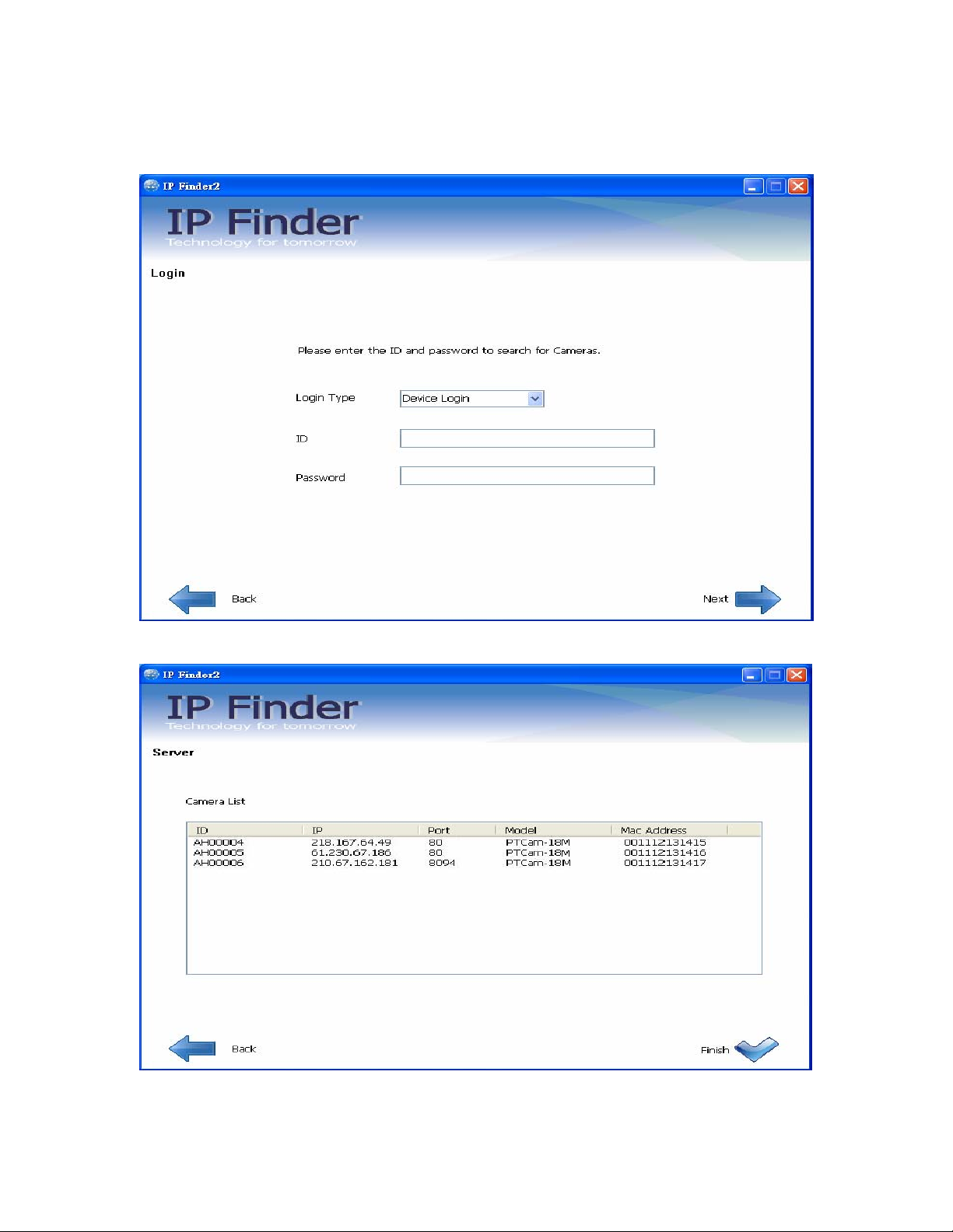
Search in Intranet
This is used to search the IP address of Network Cameras or Video servers on a NAT
Server.
Search and connecting the camera in internet from Server
19/62
Page 20
Network Camera User’s Manual
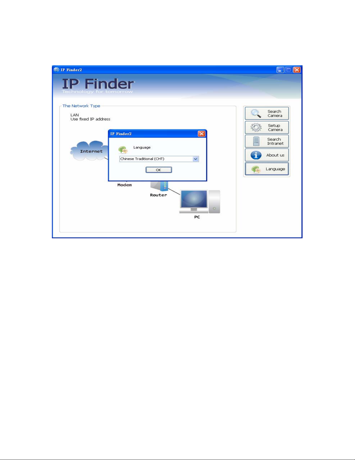
Setup Language
Click this button to choose a language for the user interface. Language options are
available in: English and Chinese、Japanese.
20/62
Page 21
Network Camera User’s Manual
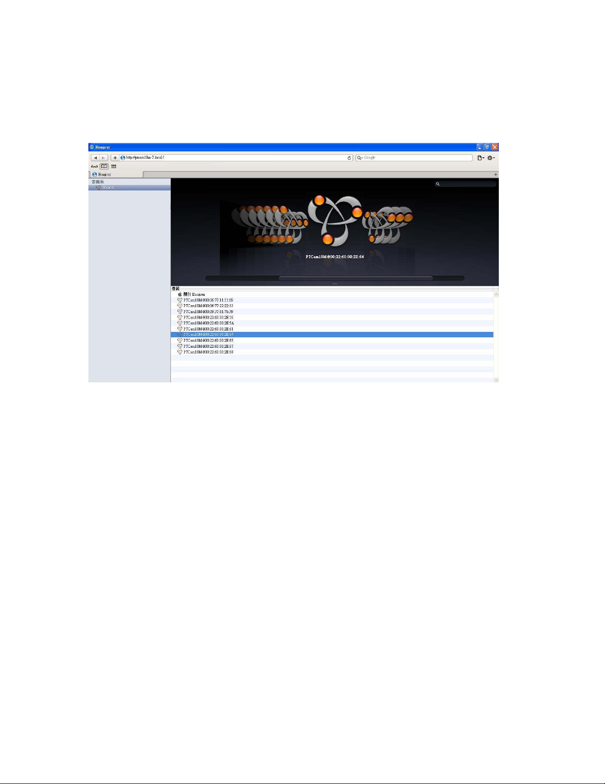
Bonjour program
Safari browser supports Bonjour search program the will search for all family network
devices on the same LAN.
21/62
Page 22
Network Camera User’s Manual
ip-discovery.com(Free DDNS service)
1.
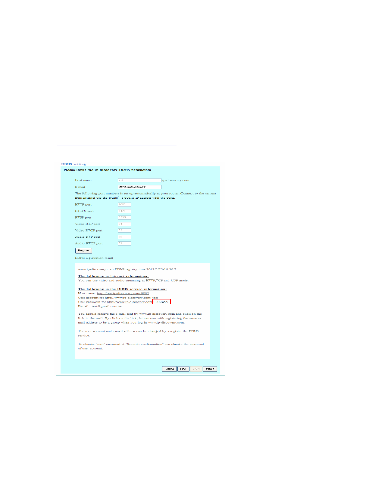
When you want to connect the network camera over Internet, you can use the
service “ip-discovery.com”. The “ip-discovery.com” is a free DDNS server for this
camera. Make sure that the router must start UPnP and DHCP server functions.
You can get the domain name which you wish very easily after registration. In
Network page—DDNS settings of this camera, you just input the host name you
want and your e-mail address, and click “Register”, then you can have the
hostname for this camera not longer than 20 seconds if the DDNS registration
result is OK. Then you can connect to this ip camera by
*
http://XXX.ip-discovery.com:@@@@
*XXX: the host name you type
*@@@@: the HTTP port (get it automatically by ip-discovery server)
User password: Default the password is last six number of the MAC. To change “root”
password at “Security configuration” can change the user password, This “User
password” is entered in the ip-discovery.com Password.
Note: You must set the ports between your router and camera manually if the registration
is failed.
22/62
Page 23
Network Camera User’s Manual
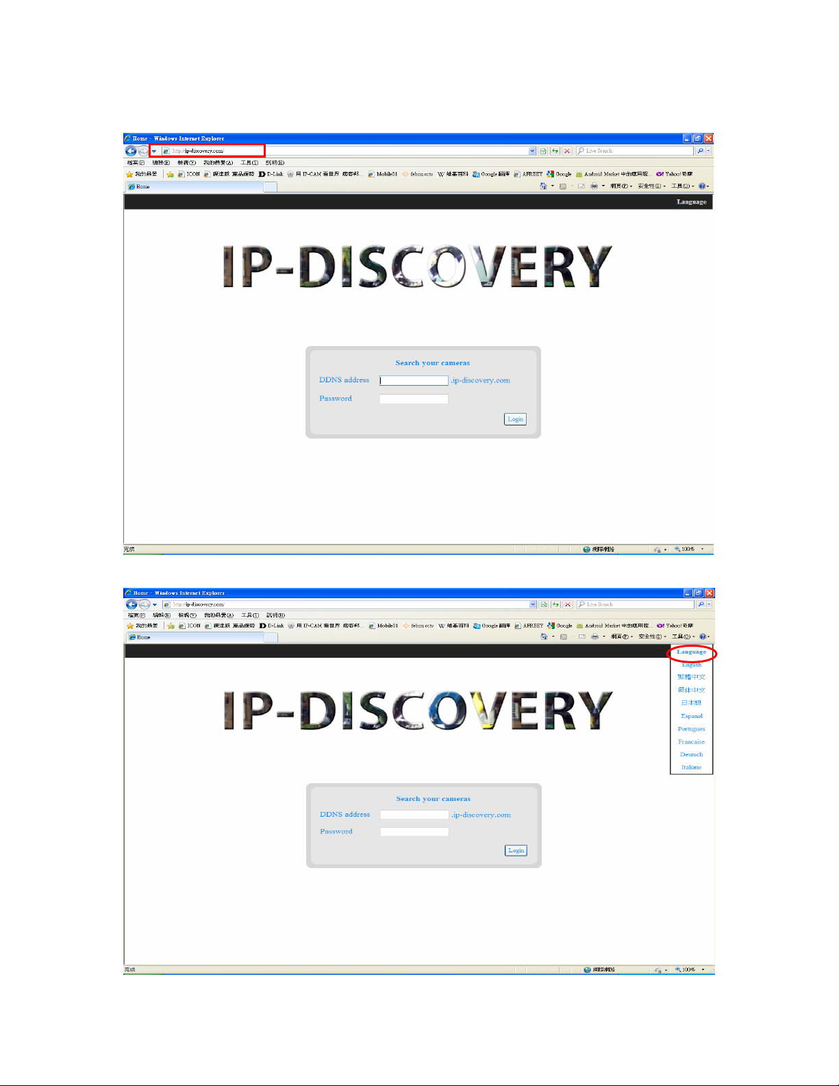
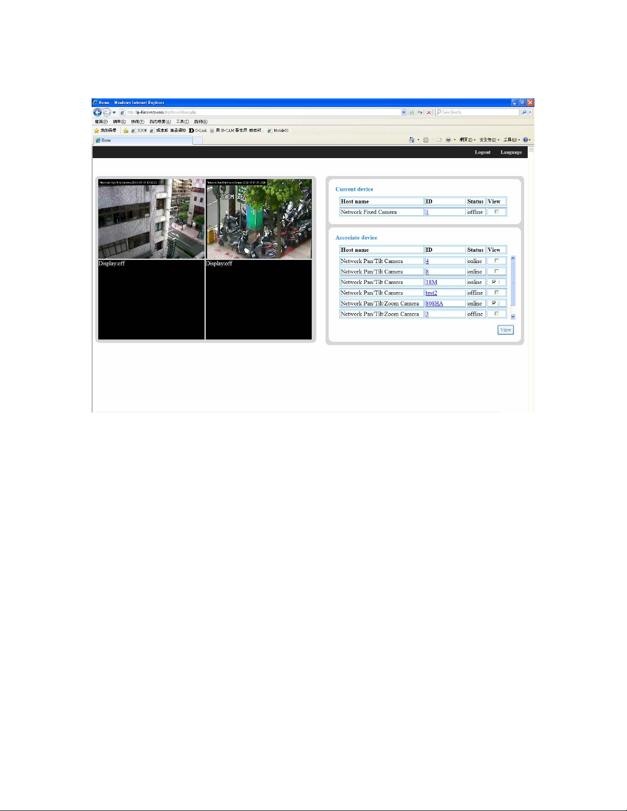
2. The free server is acted as an internet IP finder. For more services from the free
Server, just running IE browser and input the host name http://ip-discovery.com/
Select language.
23/62
Page 24
Network Camera User’s Manual
Current device
In other cameras in the same registered e-mail will become a group.
24/62
Page 25
Network Camera User’s Manual
Initial Access to the Network Camera
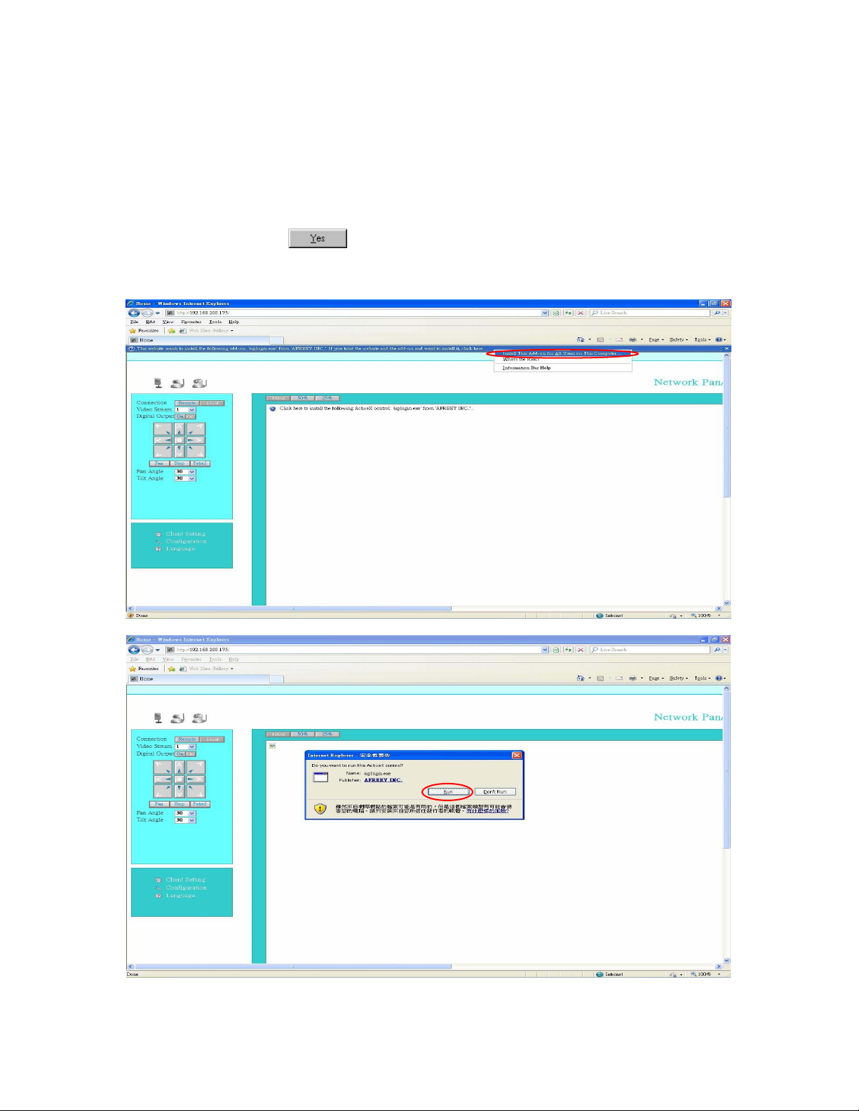
(1) For the initial access to the Network Camera in Windows, the web browser may
prompt for permission to install a new plug-in for the Network Camera. This plug-in
has been registered for certificate and is used to display the video in the browser.
Users may click on
1. Click “Install” and “Run” ActiveX controls
to proceed.
Note: he current ActiveX does not support web browser IE9 64-bit version.
25/62
Page 26

Network Camera User’s Manual
2.The video will be displayed.
26/62
Page 27
Network Camera User’s Manual
Primary user’s capability
Main Screen with Camera View
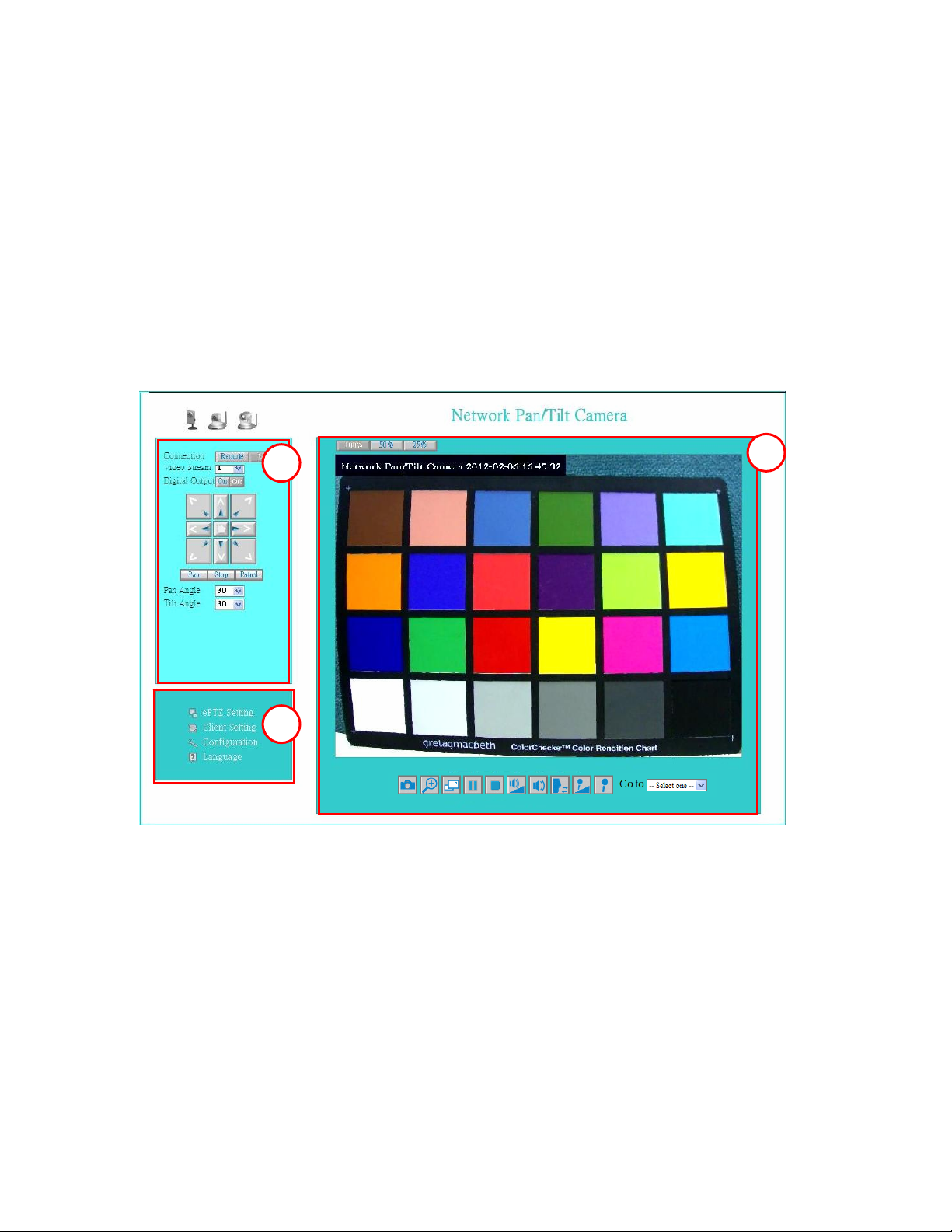
The main page has three parts:
1. Configuration functions: The camera can be configured using these user
interfaces.
2. Pan/Tilt & connection control buttons: These buttons provide the direction to
control the pan and tile of camera.
3. Camera View: What the camera sees.
Click the configuration in the bottom of left column to link to the configuration page.
Configuration functions:
“ePTZ Settings“ Electronic pan/tilt/zoom capabilities that enable users to move
to a target region instantly for close-up shots by simply clicking on the video
feeds on their screen rather than moving the camera physically.
“Client Settings” Clicking on this button links you to the client setting pages,
please check the following session for more details.
“Configuration” Please notes that only the administrator can access it.
“ Language” Click this button to choose a language for the user interface.
Language options are available in: English, traditional Chinese, Simplified Chinese,
Japanese, Spanish, Portuguese, French, German, ltaliano.
Note: ePTZ function only in the image size of 1280x1024 the following screen, this
feature will appear.
Camera view:
27/62
Page 28
Network Camera User’s Manual
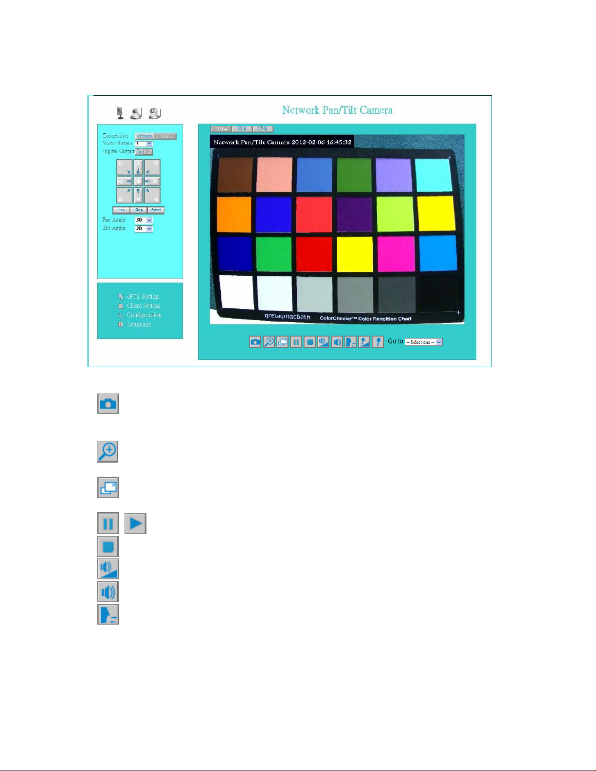
On the top of image shows the connecting type of the Network Camera and the current
date/time.
View capabilities:
1. Click this button to capture and save still images. The captured images will be
displayed in pop-up window. Right-click the image and choose Save Picture As to save it
in JPEG format.
2. The button selection lets you open a digital zoom, and to control the window to
enlarge a specified area in the camera view.
3. Click this button to switch to full screen mode. Press the “Esc” key to switch back
to normal mode.
4. Click on this button freeze the video, and playing when you click again.
5. Click on this button stop video output.
6. Click on this button adjust the audio volume & Latency.
7. Click on this button switch Mute On/Off.
8.
Enable this function, request insert an external speaker. The server can play sound from
the client and receive sound from the environment and send to client.
Click on this button to adjust the Function “2-way audio” to be Enable/Disable.
9.“Go to” Once the Administrator has determined the preset positions; the User can
aim the camera using this control.
28/62
Page 29
Network Camera User’s Manual
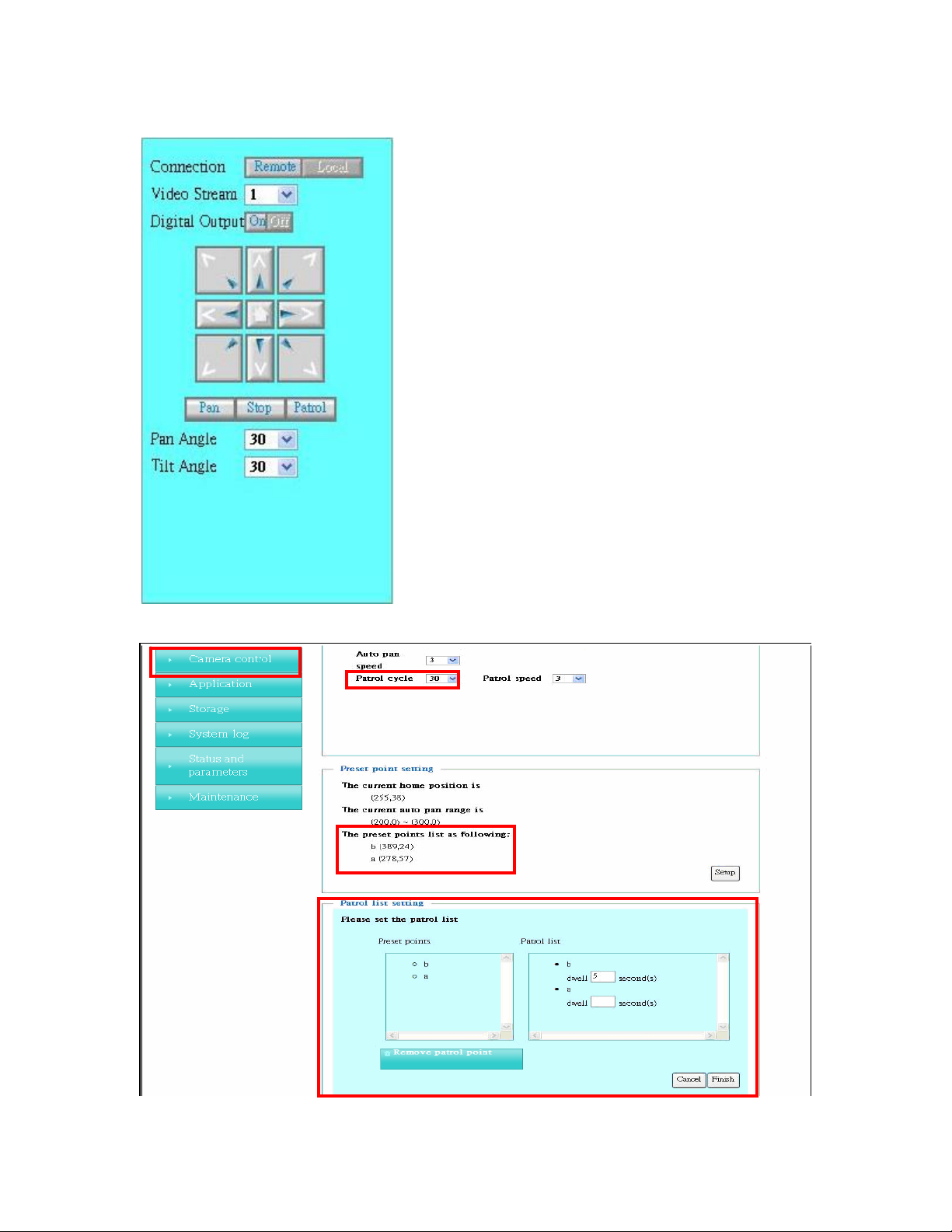
Pan/Tilt & connection control buttons:
1. “Connection” User can choose Remote or
Local mode for best connection qu
Proposal: Internet environment, switch Remote
mode.
ality.
2. “Video Stream” User can choose stream1 or
stream2.
3. “Digital Output” Clicking on the “On” or “Off”
button turns the digital output to either on or off
status.
4. “The direction buttons are” “Left”, “Right”, “Up”,
“Down”, “Cross Angles”, and “Home”. Camera
returns to center when click “Home”
button
5. “Pan Speed” User can choose the speed when
the camera moves left and right each time.
6. “Tilt Speed” User can choose the speed when
the camera moves up and down each time.
7. “Pan” The camera will move from right side to
left side continuously when click the button
.
8. “Stop” User can stop the movement of camera,
such as Auto pan, Auto Patrol, and etc., by clicking
the button.
9. “Patrol” The button directs the camera to patrol
among the preset positions in the patrol list, which
can be modified on the “Camera control page”. The cycle of patrol is from 1 to
Unlimited.
29/62
Page 30
Network Camera User’s Manual
Client Setting
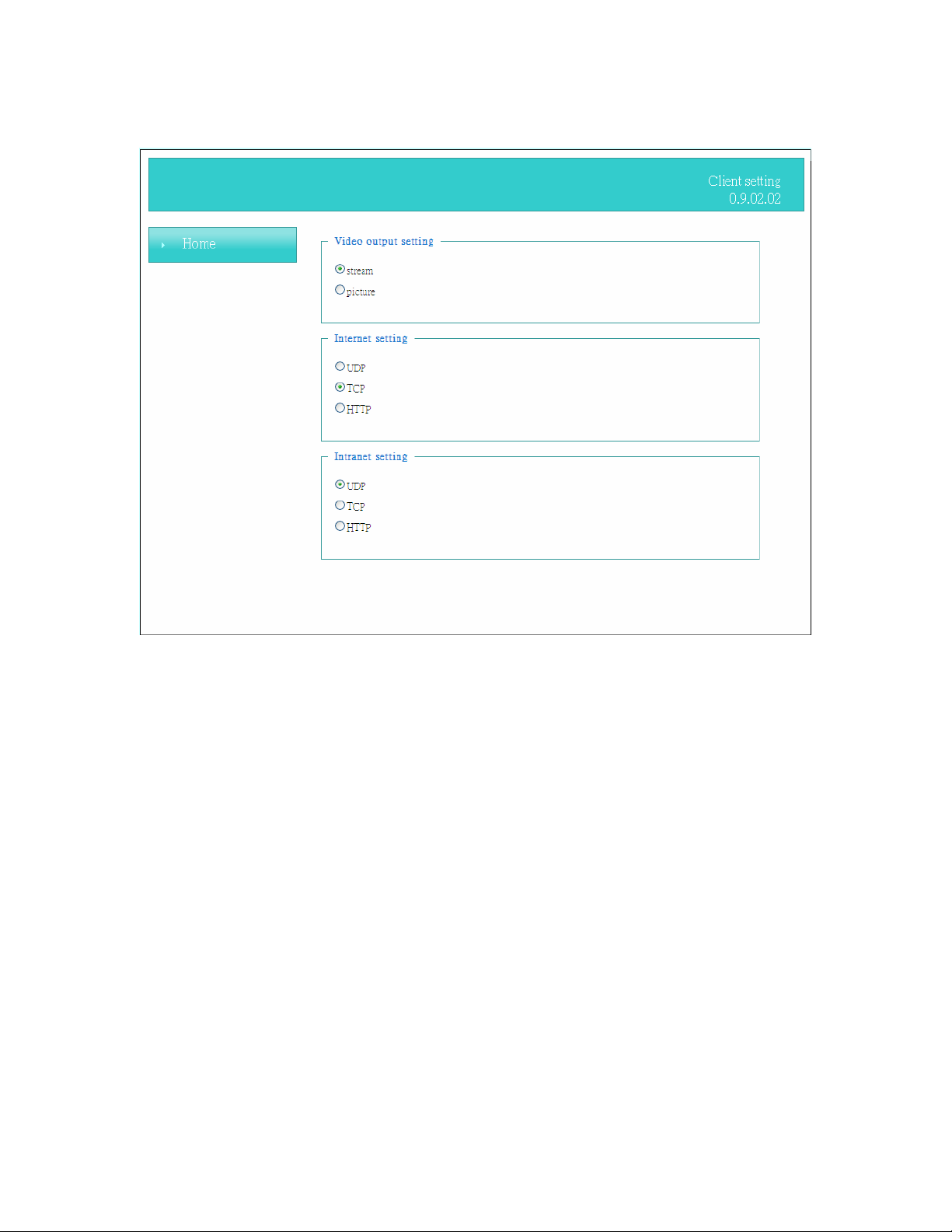
1. “Video output setting” Setting video output format.
“Stream” Select use multiple stream video.
“Picture” Select use serial video picture.
2. “Intranet Protocol Options” Setting camera in intranet mode of protocol.
“UDP” Select use UDP protocol connect camera.
“TCP” Select use TCP protocol connect camera.
“HTTP” Select use HTTP protocol connect camera.
3. “Internet Protocol Options” Setting camera in internet mode of protocol.
“UDP” Select use UDP protocol connect camera.
“TCP” Select use TCP protocol connect camera.
“HTTP” Select use HTTP protocol connect camera.
NOTE:Protocol Options which allows choices on connection protocol between client and
server. There are three protocols choices to optimize your usage – UDP, CP, HTTP.
The UDP protocol allows for more real-time audio and video streams. However, some
packets may be lost due to network burst traffic and images may be obscured.
The HTTP protocol allows for less packet loss and produces a more accurate video
30/62
Page 31

Network Camera User’s Manual
display. The downside with this protocol is that the real-time effect is worse than that with
the UDP protocol.
The TCP guarantees the complete delivery of streaming data and thus provides better
video quality. However, the real-time effect is not as good as that of the UDP protocol.
If no special need is required, UDP protocol is recommended. Generally speaking, the
client choice will be in the order of UDP → HTTP. After the Network Camera is
connected successfully, “Protocol Option” will indicate the selected protocol. The
selected protocol will be recorded in the user's PC and will be used for the next
connection. If the network environment is changed, or the user wants to let the web
browser to detect again, manually select the UDP and TCP protocol, save, and return
HOME to re-connect.
31/62
Page 32
Network Camera User’s Manual
Definitions in Configuration
Please note that only the Administrator can access the system configuration.
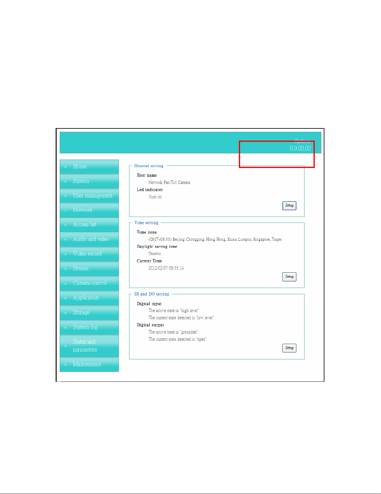
System parameters
Firmware version
“General Setting”
(1) “Host name”
The text displays the title on the top of the main page.
(2) “LED indicator”
Select turn on or turn off the led indicator.
32/62
Page 33

Network Camera User’s Manual
2. “Time Setting”
(1) “Time zone”
Choose a time zone from the down arrow.
(2) “Daylight saving”
For summertime; It will be one hour ahead.
(3) “Current Time”
Network camera set the current time.
(A) “Keep current date and time”
Click on this to keep the current date and time of the Network Camera. An internal
real-time clock maintains the date and time even when the power of the system is
turned off.
(B) “Sync with computer time”
Synchronize the date and time in the Network Camera according to the local
computer.
(C) “Manual”
Adjust the date and time by the Administrator.
(D) “Adjust by NTP server”
Synchronize the time according NTP server over the Internet whenever the Network
Camera is switched on. It fails if the assigned time-server cannot be found.
(a) “NTP server” Assign the IP address or domain name of the time-server.
Leaving the text box blank connects the Network Camera to the default
time-servers.
(b) “Update interval” Select 0 ~ 23 hours update with the time on the NTP
server.
3. “DI and Do Setting”
Select Open or Ground to define the DO active state.
Remember to click on “Finish” to immediately validate the changes. Otherwise, the
correct time will not be synchronized.
33/62
Page 34
Network Camera User’s Manual
Security
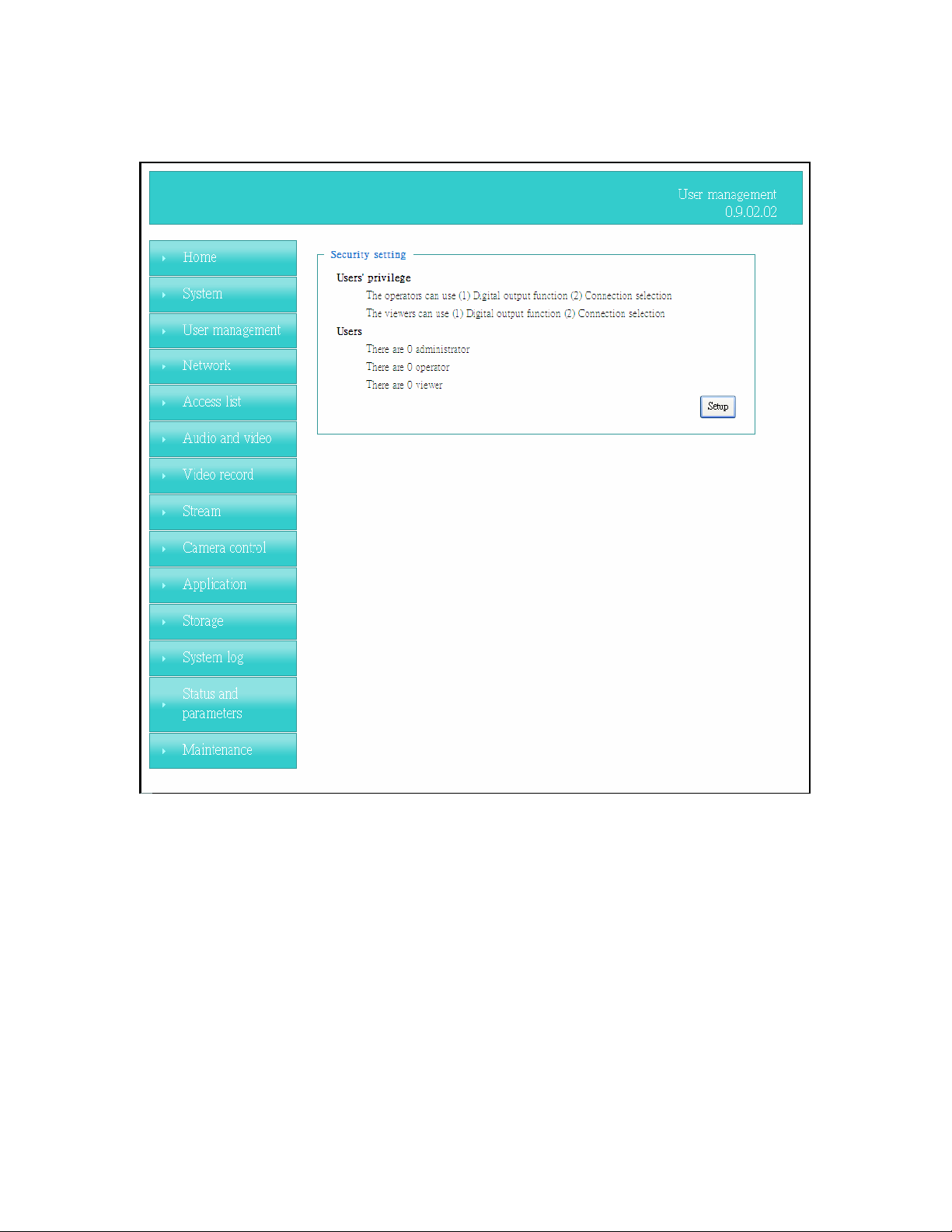
Security setting
The administrator account name is
If you want to add more accounts in the Manage User column, please set a password for
the “root” account first. Network Camera can provide twenty accounts for your valuable
customers or friends.
1. “Change root password”
new password identically in both text boxes. The typed entries will be displayed as
asterisks for security purposes. After pressing “finish”, the web browser will ask the
Administrator for the new password to access.
Change the Administrator’s password by typing in the
“root”, which is permanent and can not be deleted.
2. “Manage privilege” You can modify the manage privilege of operators or viewers.
Check or uncheck the item, then click finish to enable the settings.
3 “Manage user”
“Add a new user” Administrators can add up to 20 user accounts.
(1)
(A) Input the new user’s name and password.
34/62
Page 35

Network Camera User’s Manual
(B) Select the privilege level for the new user account. Click Finish to enable the
setting.
(2) “Delete a user” Select an existing user name. Click Finish to enable the
setting.
(3) “Update a existing user” Select an existing user name. Administrators can
modify user’s password and
Access rights are sorted by user privilege (Administrator, Operator, and Viewer). Only
administrators can access the Configuration page. Operators cannot access the
Configuration page but can use the URL Commands to get and set the value of
parameters. Viewers access only the main page for live viewing.
privilege. Click Finish to enable the setting.
35/62
Page 36
Network Camera User’s Manual
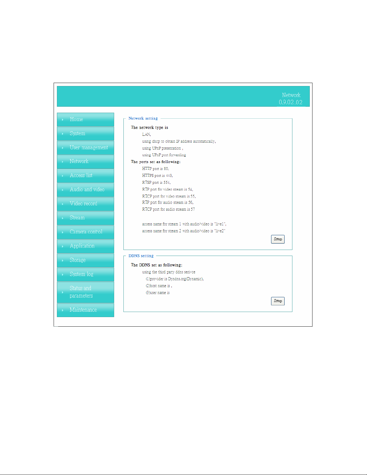
Network
Any changes made on this page will restart the system in order to validate the changes.
Make sure every field is entered correctly before clicking on “finish”
Network Setting
“LAN” 、 “PPPoE”
The default type is LAN. Select PPPoE if using ADSL
1. LAN
The default status is Get IP address automatically. This could be tedious to perform
software installation whenever the Network Camera starts. Therefore, once the network
is set, especially for the IP address should be entered correctly. Select Use fixed IP
address then the Network Camera will skip installation. The Network Camera will
automatically restart and operate normally after a power outage. You can run IP installer
to check the IP address assigned to the Network Camera if the IP address is forgotten,
36/62
Page 37

Network Camera User’s Manual
or you can use the UPnP function provided by the Network Camera (MS Windows XP
provides UPnP function at My Network Place).
(1) “Get IP address automatically”
(2) “Use fixed IP address”
- “IP address”: This is necessary for network identification.
- “Subnet mask”: This is used to determine if the destination is in the same
subnet. The default value is “255.255.255.0”.
-“Default router”: This is a gateway used to forward frames to destinations
in a different subnet. Invalid router setting will fail the transmission to
destinations in different subnet.
- “Primary DNS”: The primary domain name server that translates
hostnames into IP addresses.
- “Secondary DNS”: Secondary domain name server backups the Primary
DNS.
- “Enable UPnP presentation & port forwarding”: Enable UPnP ability.
- “Http port” This can be typed besides the default Port 80. Once the port is
changed, the users must make sure the change for the connection is successful.
For instance, when the Administrator changes the HTTP port of the Network
Camera which IP address is 192.168.0.20 from 80 or 1025 to 65535, the users
must type in the web browser “http://192.168.0.20:8080” instead of
“http://192.168.0.20”.
- “RTSP Port” RTSP port can be typed besides the default Port 554
- “RTP Port” The RTP port can be typed besides the default Port 54
Note: Please set Video RTP port in even number after default value port 54. Then,
Video RTCP pot、Audio RTP port、Audio RTCP port will automatically set the
values in ascending.
- “RTSP Streaming access names” The RTSP streaming currently supports
video only, audio only, and audio/video. To use the audio/video stream, type the
URL as“rtsp://61.30.125.43/liveN.sdp”.
2. PPPoE
If using the PPPoE interface, you should fill the following settings from ISP.
(1) “User name”: The login name of PPPoE account
(2) “Password”: The password of PPPoE account
(3) “Confirm password”: Input password again for confirmation
DDNS Setting
1. “Enable DDNS” This option turns on the DDNS function.
2. “ip-discovery” In the Register column, fill in the Host name (xxxx. ip-discovery),
Email, Key, and Confirm Key, then click Register. After a host name has been
successfully created, a success message will be displayed in the DDNS Registration
Result column and messaging E-mail.
3. “3rd party DDNS” This is enable or disable 3
4. “Provider”
connect to the service provider’s website to make sure the service charges.
The provider list contains hosts that provide DDNS services. Please
5. “Host Name” If the User wants to use DDNS service, this field must be filled.
Please input the hostname that is registered in the DDNS server.
6. “User name” The Username or E-mail field is necessary for logging in the DDNS
rd
party DDNS.
37/62
Page 38

Network Camera User’s Manual
server or notify the User of the new IP address.
Note: when this field is input as “User name”, the following field must be input as
“Password”.
7. “Password” Please input the password or key to get the DDNS service.
8. “Finish” Click on this button to save modify settings for the DDNS service.
38/62
Page 39
Network Camera User’s Manual
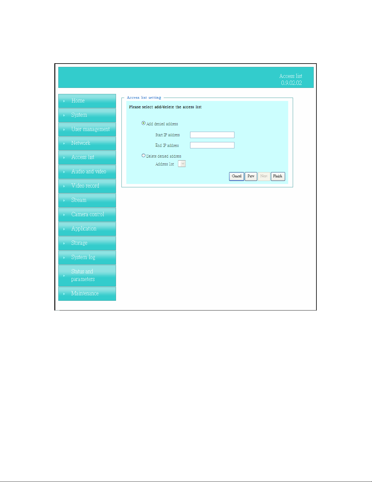
Access list
Access list setting
1. “Add denied address” This rule allows the user to assign a range of IP
addresses to the Deny List.
2. “Delete denied address“ Delete IP address list from the Address List.
39/62
Page 40
Network Camera User’s Manual
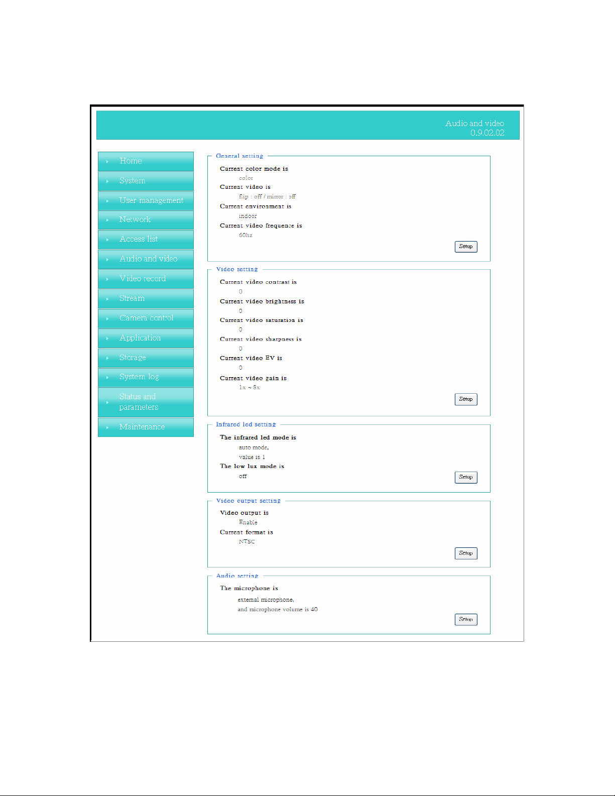
Audio and Video setting
General Setting
1. “Color mode” Select use color or monochrome video display.
2. “Video orientation” The orientation of video
(1) “Flip” Vertically rotate the video.
40/62
Page 41

Network Camera User’s Manual
(2) “Mirror” Horizontally rotates the video.
3. “Environment” The orientation of video
(1) “indoor” This option is usually selected when the Network Camera is placed
in indoor environments.
(2) “outdoor” This option is usually selected when the Network Camera is
placed in outdoor environments.
4. “Power freq.” Select 50 Hz or 60Hz power line frequency.
The fluorescent light will flash according to the power line frequency that
※
depends on local utility. Change the frequency setting to eliminate uncomfortable
flash image when the light source is only fluorescent light.
Video Setting
1. “Contrast” Adjust the image contrast level, which ranges from -5 to +5. The default
value is set to 0.
2. “Brightness” Adjust the image brightness level, which ranges from -5 to +5. The
default value is set to 0.
3. “Saturation” Adjust the image saturation level, which ranges from -5 to +5. The
default value is set to 0.
4. “Sharpness” Adjust the image sharpness level, which ranges from -5 to +5. The
default value is set to 0.
5. “EV” Exposure value represent the expected target value of the luminance of
the weighting result of AE windows in the image and its tolerance as offset.
6. “Gain” In the slide bar of Gain, there are also two sliders, which represent the
limitations to control the maximum gain value and the minimum one, respectively.
Normally, the minimum value is to 1x for better quality.
Infrared Led Setting
1. “Infrared LED Control” IR led for Day and Night (Option). User can turn on/off
the built-in IR led. This function is very useful under low illumination environment.
(1) “Auto” Select IR sensitivity from 0 to 4.
(2) “Manual” Turn on/off the IR led manually.
- “Turn on” Turn on led
- “Turn off”
Turn off led
2. “Low lux mode” The video quality will be improved when the camera is in low
lux environment.
(1) “Disable dark mode” Disable low lux mode.
(2) “Enable dark mode” Enable low lux mode.
Audio Setting
1. “Mute” Audio mute.
1. “Microphone Select ” External microphone select.
2. “Mic Volume” Adjust microphone volume, which ranges from 1 to 46. The default
value is set to 40.
41/62
Page 42
Network Camera User’s Manual
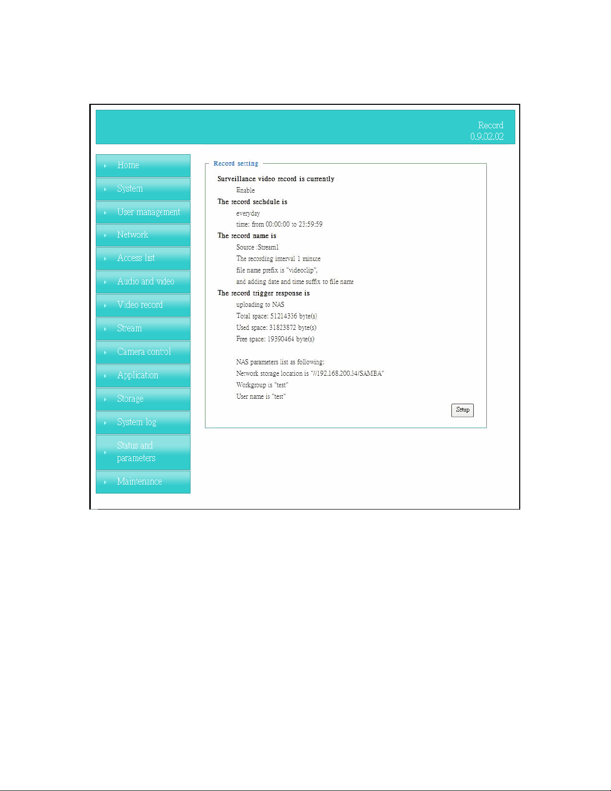
Video record
Schedule mode
(1) “Every day”
Enable/Disable every day application.
(2) “Week day” Enable/Disable week day application.
(3)“Selected day” Enable/Disable selected day application.
Schedule information
(1)
Enter the “Start time” and “Stop time” for day mode.
Note that the time format is [hh:mm] and is expressed in 24-hour clock time. By
default, the start and end time of day mode are set to 01:00:00 and 23:59:59.
(2)“Sun”/“Mon”/“Tue”/“Wed”/“Thu”/“Fri”/“Sat” Select the days of the
week to perform the application.
(3) “Start day” and “Start time” as the start timing the time. “End day” and
“End time” as the end timing the time
(4) “Enable cyclic recording” The cyclic recording function is enabled, during the
transaction stage when a storage space is full and the incoming streaming data is about
42/62
Page 43

Network Camera User’s Manual
to overwrite the previously saved videos.
Record parameters
(1)Source: Select a stream for the recording source.
(2)Recording interval: Select the recording time interval.
(3)Prefix file name: You can setting the file name, and enable or disable to
add the date and time on file name.
Response mode There are three choices of server types available: NAS, SD Card,
and USB storage. Select the item to display the detailed configuration options.
(1)”NAS”
--“NAS server address” Enter IP address of the NAS server.
--“NAS shared directory” Enter the NAS shared directory path.
--“Workgroup” Enter the NAS workgroup parameter.
--“User account” Enter the login name of the NAS account.
--“User password” Enter the password of the NAS account.
Note: Video record with the Application must be set to the same shared directory path. If
you would like do detail recording settings or multi-channel recording, please install
bundled 64CH recording software in CD.
43/62
Page 44
Network Camera User’s Manual
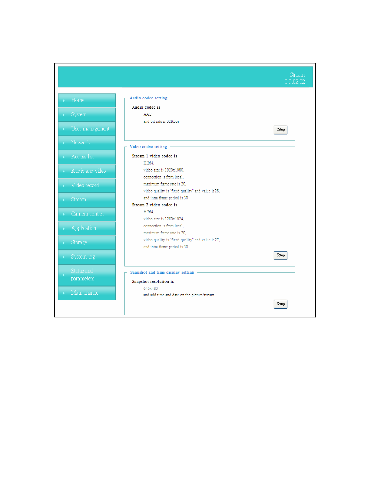
Stream
Audio codec setting
(1)“Audio codec type” There are two choices of audio codec types
available:
(2) “Bit rate”
”AMR” and “AAC”.
-- “AMR” The bit rates are selectable at the following rates:
4750,5150,5900,6700,7400,7950,10200 and 12200.
-- “AAC” The bit rates are selectable at the following rates:
8Kbps,16Kbps, 24Kbps and 32Kbps.
Video codec setting
(1) “Select Stream”
The Network Camera supports “Stream 1”and “Stream 2”.
(2) “Video codec” The Network Camera supports three kind of video
compression mode: “H.264” or “MPEG4” or “MJPEG”. User can choose one of
these compression modes based on requirement or application
44/62
Page 45

Network Camera User’s Manual
(3) “Video size” Click the down arrow to choose the quality of image
(1920x1080, 1280x1024, 1280x800, 640x480, 320x240, 176x144)
(4) “Connection type” User can select this button to choose the better video
& links quality. (Internet mode or Intranet mode)
(5) “Frame rate” This limits the maximal refresh frame rate per second. Set the
frame rate higher for a smoother video quality.
(6) “Intra frame period” Determine how often to plant an “I frame”. The shorter
the duration, the more likely you will get a better video quality, but at the cost of
higher network bandwidth consumption.
(7) “Video Quality type” Setting optimizes bandwidth utilization and video quality.
-- “
Constant bit rate” User can adjust the video quality from 20 Kbps to 12
Mbps.
Fixed quality” user can select from lowest quality to get best quality
-- “
according. The “Quality” are selectable at the following rates: From 21 to 40.
Snapshot and time display setting
Adjust the photo size specifications and choose whether to mark time on the
video and photo.
45/62
Page 46
Network Camera User’s Manual
Camera control
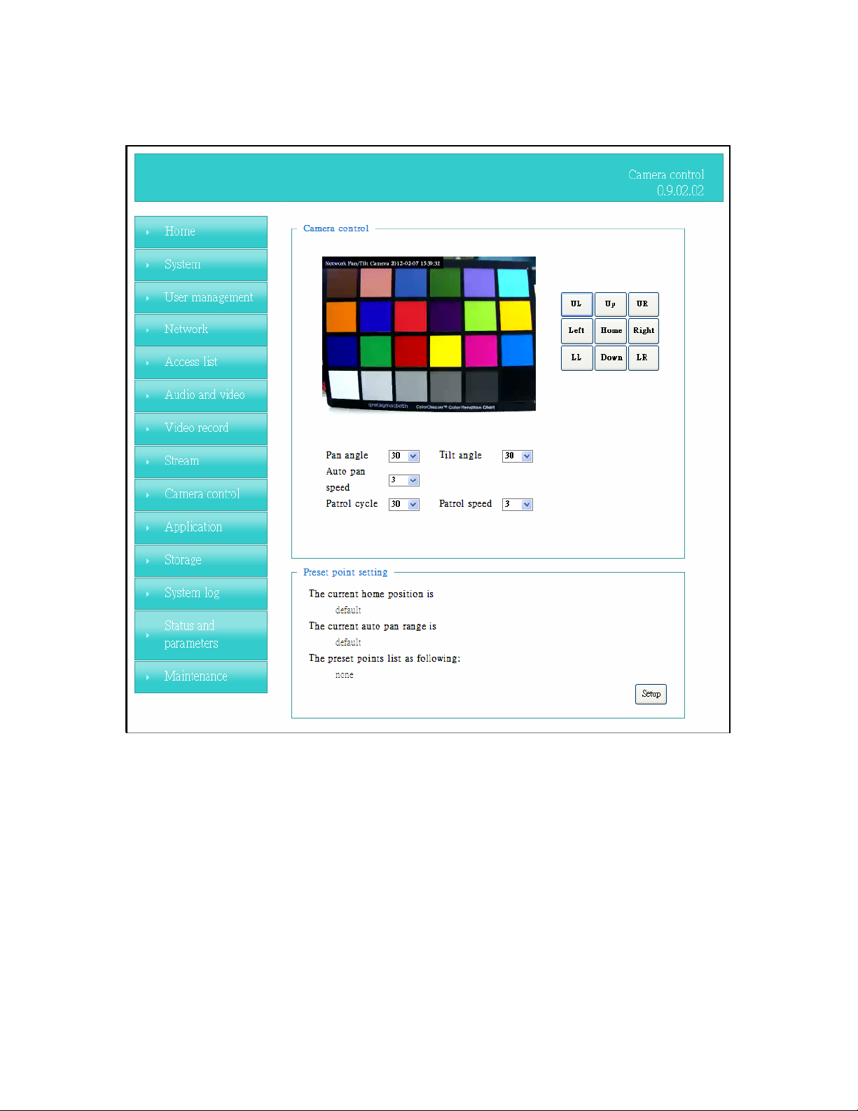
Camera control
The pan and tilt functions can be controlled with these buttons. The “Left” button
controls the camera to the left; the
camera accordingly.
“Right”, “Up”, and “Down” buttons control the
(1) “UL”, “UR”, “LL” and “LR” buttons control the camera to an oblique angle.
“Home” button controls the camera to the center.
And
(2)“Pan speed” This sets the range of the horizontal movement of the camera. The
larger value is setting, the larger movement of
camera.
“Left” or “Right” is performing by the
(3) “Tilt speed” This sets the range of the vertical movement of the camera. The
larger value is setting, the larger movement of
camera.
“Up” or “Down” is performing by the
(4) “Patrol cycle” It is the cycle of patrol function.
46/62
Page 47

Network Camera User’s Manual
(5) “Auto pan speed” This defines the speed of auto panning. The larger value is
setting, the faster speed will run by the camera.
(6) “Auto patrol speed” This defines the speed of auto patrol. The larger value is
setting, the faster speed will run by the camera.
Preset point setting
(1) “Set the home position”
--“Set default value as home position” Restore home position to original
default’s home by clicking on this button.
--“Set the current position as home position” Click on the button will set the
current aimed position as home of the Network Camera. Each time the Network
Camera reboots or finishes calibration, it will automatically aim to the defined home
position
(2) “Set the auto pan range”
--“Set default value as auto pan range” Restore auto pan range to original
default’s auto pan range by clicking on this button.
--“Set the auto pan range manually” Click on the button will set the auto pan
range of the Network Camera.
(3)”
Add or delete a preset point”
--“Add current point as a preset point” If the User wants to save the current
view as a preset location, enter a name to each of the current video view on
“Preset points” and click on the “Finish” button. The camera allows for 20
preset locations.
--“Delete a preset point from below” This keeps a list for preset positions.
Clicking on the “Finish” button will remove the current selected position from the
preset list.
Patrol list setting
(1) ”Preset points” The preset points box list all preset points. User must use
to drag the preset points to “Patrol list” box when the action is recognized
the “Patrol list” box change to red.
Patrol list” The Patrol list box list all patrol points. User use the drag to
(2) “
adjust of the patrol point (Up or down). Dwelling time (sec)” The stop time of
each preset location during auto patrols of the Network Camera.
(3) “Remove patrol point” The remove patrol point box will remove the patrol
point.
47/62
Page 48
Network Camera User’s Manual
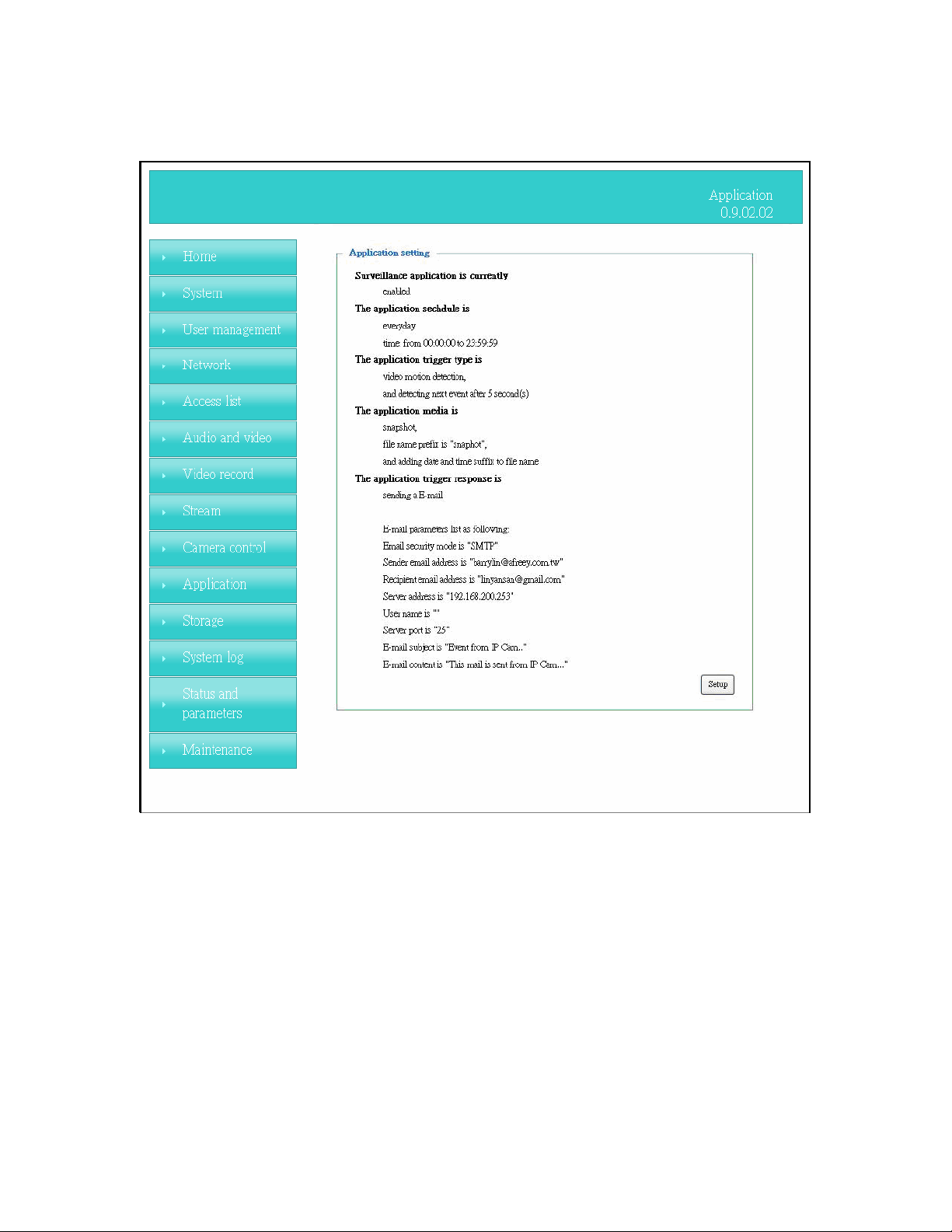
Application
Schedule mode
(1) “Every day” Enable/Disable every day application.
(2) “Week day” Enable/Disable week day application.
(3) “Selected day” Enable/Disable selected day application.
Schedule information
(1)
(3) “Start day” and “Start time” as the start timing the time. “End day” and
Enter the “Start time” and “Stop time” for day mode.
Note that the time format is [hh:mm:ss] and is expressed in 24-hour clock time. By
default, the start and end time of day mode are set to 01:00:00 and 23:59:59.
(2) “Sun”/“Mon”/“Tue”/“Wed”/“Thu”/“Fri”/“Sat” Select the days of the
week to perform the application.
“End time” as the end timing the time
48/62
Page 49

Network Camera User’s Manual
Trigger mode
(1) “Video motion detection” Enable/Disable video motion application
Periodically” This option allows the Network Camera to trigger
(2) “
periodically for every other defined minute.
(3) “Digital input” This option allows the Network Camera to use an external
digital input device or sensor as a trigger source. Depending on your application,
there are many choices of digital input devices on the market which helps to
detect changes in temperature, vibration, sound, and light, etc.
parameters
(1) “Motion parameters”
Higher sensitivity and small threshold will allow easier motion detection.
(2) “Period parameters” This option allows the Network Camera to trigger
periodically for every other defined seconds. Up to 999 seconds are allowed.
(3) “Digital input parameters” Select the digital input type and set trigger time.
Media mode
There are three choices of media types available: “Snapshot”,” Generate digital
output signal”, “Record (Motion Detection only)” and “System log”.
Snapshot & Record file setting
You can setting the file name, and enable or disable to add the date and time
on file name. Can setting the digital output duration seconds.
Response mode
There are five choices of server types available: Email, FTP, NAS, SD Card, and USB
storage. Select the item to display the detailed configuration options.
(1)“Email”
-- “Email security mode”: If your SMTP server requires a secure connection
(SSL or TLS), check This server requires a secure connection (SSL or TLS).
-- “Sender email” address: Enter the email address of the sender.
-- “Recipient email” address: Enter the email address of the recipient.
-- “Server address” Enter the domain name or IP address of the email
server.
--“User name” Enter the user name of the email account if necessary.
--“Password” Enter the password of the email account if necessary
--“Server port” The default mail server port is set to 25. You can also
manually set another port.
(2)”FTP”
-- “Server address” Enter the domain name or IP address of the FTP server.
-- “Server port” By default, the FTP server port is set to 21.
-- “User name” Enter the login name of the FTP account
-- “Password” Enter the password of the FTP account.
-- “FTP folder name” Enter the folder where the media file will be placed. If
the folder name does not exist, the Network Camera will create one on the FTP
server.
(3)”NAS”
--“NAS server address”
Enter IP address of the NAS server.
--“NAS shared directory” Enter the NAS shared directory path.
--“Workgroup” Enter the NAS workgroup parameter.
49/62
Page 50

Network Camera User’s Manual
--“User account” Enter the login name of the NAS account
--“User password” Enter the password of the NAS account.
Note: Video record with the Application must be set to the same shared directory
path. If you would like to do detail recording settings or multi-channel recording, please
install bundled 64CH recording software in CD.
50/62
Page 51
Network Camera User’s Manual
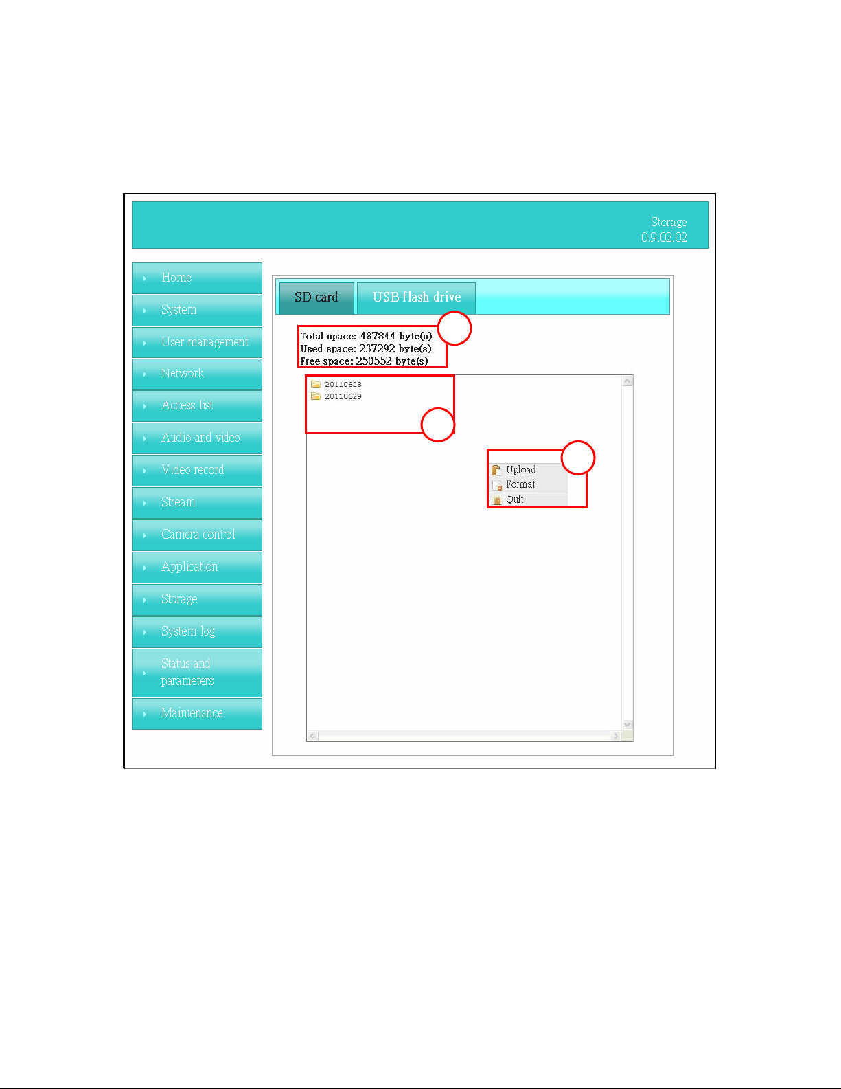
Storage
Manage the storage device (like SD card or USB flash disk).
Storage Status
Here show the storage device information.
File operation
Move the mouse over the file. Press the mouse right button that Right-click menu
is displayed. You can delete files.
Move the mouse over the directory. Press the mouse left button that the file
structure expand. Press the mouse right button that Right-click menu is displayed.
You can choose upload or delete files.
NOTE:Allow the user to upload or delete files when the storage device is not write-
protected. If the SD card can’t be detected, please link to the following URL:
51/62
Page 52
Network Camera User’s Manual
http://www.sdcard.org/consumers/formatter to download the “SD Formatter Kit”
formatting your SD card.
Syslog
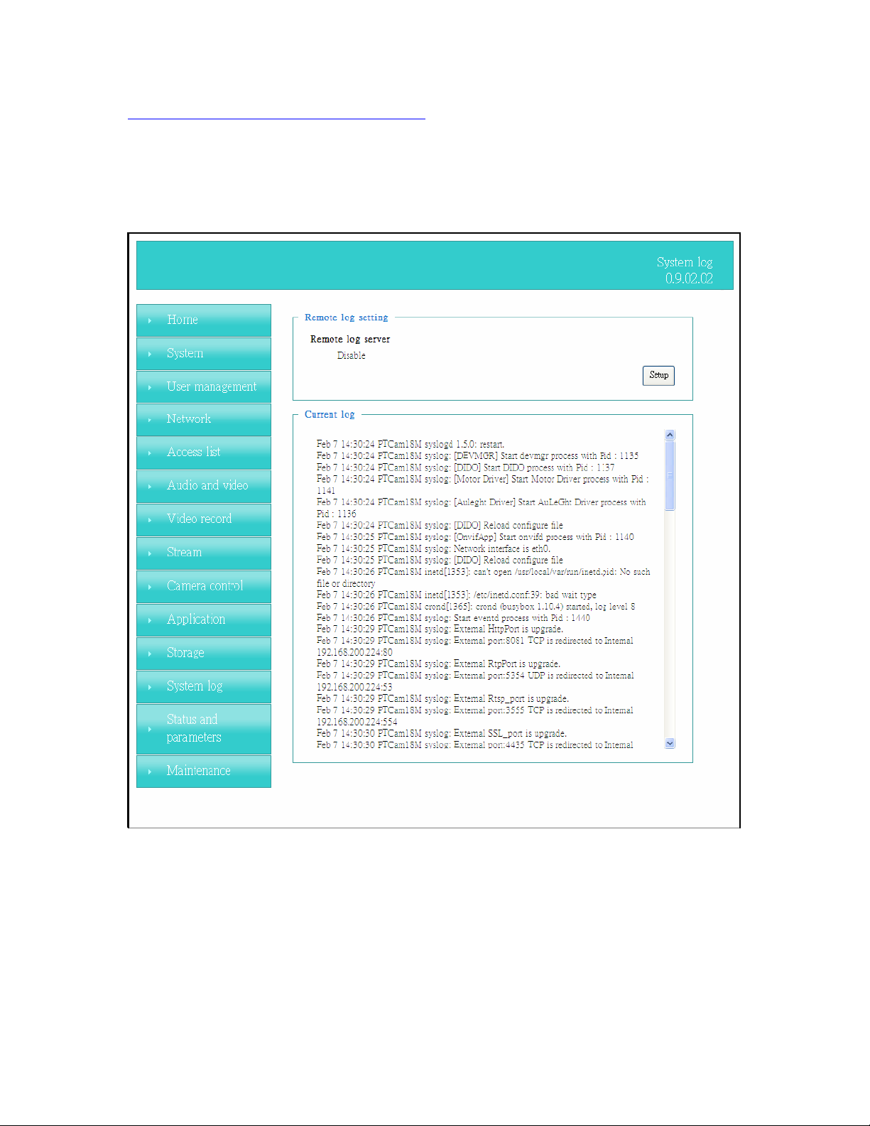
The Network camera supports log the system messages on remote server.
The protocol is compliant to RFC 3164. If you have external Linux server with sys log
service, use “-r” option to turn on the facility for receiving log from remote machine. Or
you can use some software on Windows that is compliant to RFC 3164.
Check “Setup” and “Enable” then input the “IP address” and “port” number of the log
server to enable the remote log facility.
In the “Current log”, it displays the current system log file. The content of the log
provides useful information about configuration and connection after system boot- up.
“Finish” Click on this button to save modify settings.
52/62
Page 53
Network Camera User’s Manual
Status and Parameters
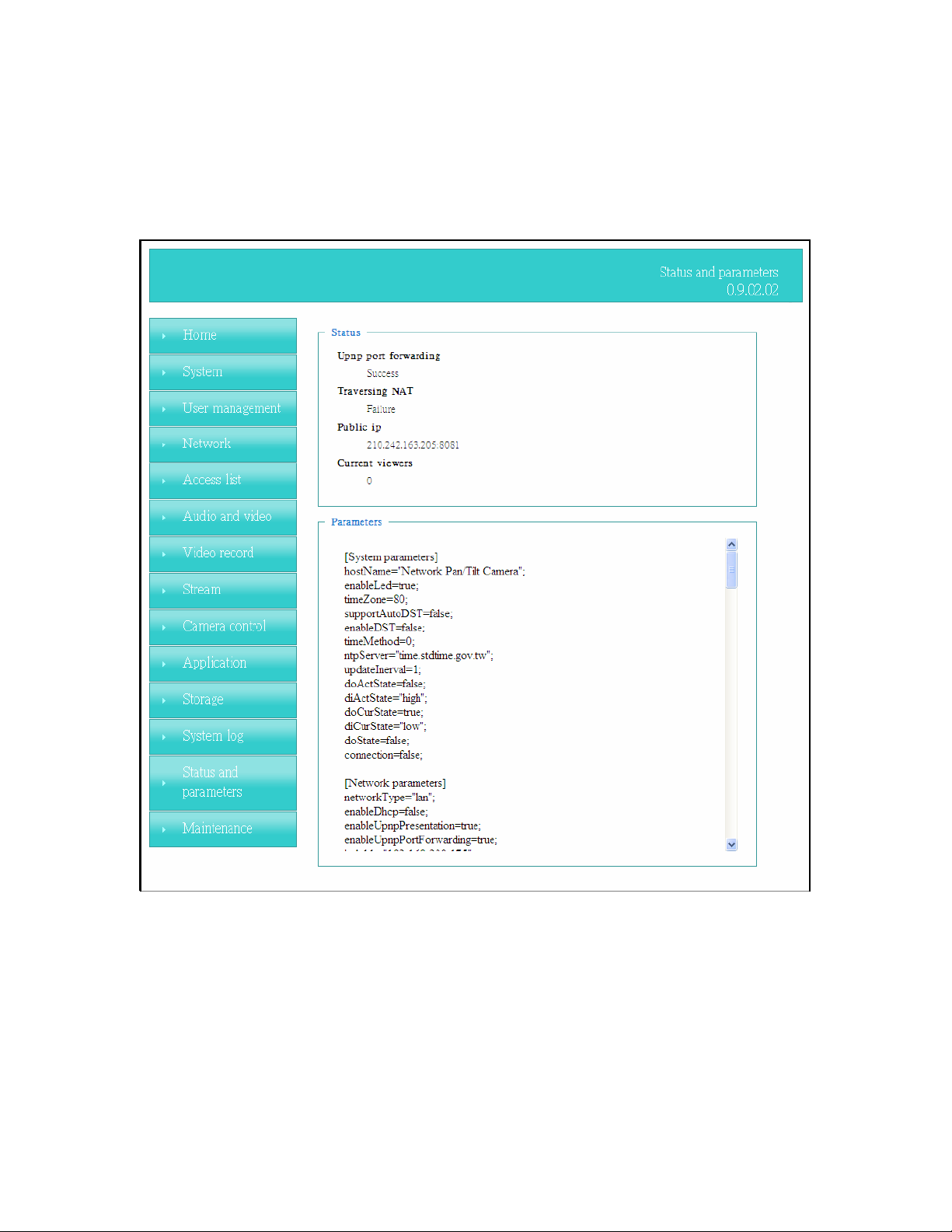
User can find a lot of information about the system such as “Upnp port forwarding”,
“Traversing NAT”, “Public IP”, and so on. User also can get the number of current
viewer of the Network Camera here.
53/62
Page 54
Network Camera User’s Manual
Maintenance
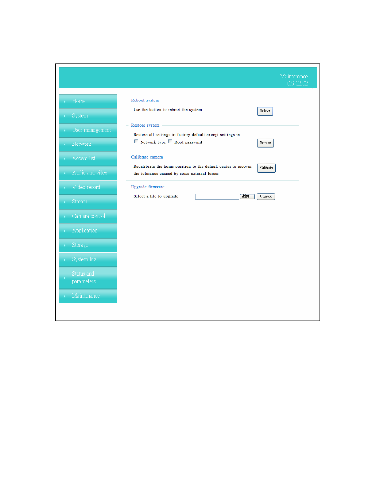
1. “Reboot system”
while the Network Camera got problem.
The “Reboot” button will reboot the Network Camera. It’s useful
2. “Restore system” Click on “Restore” button on the configuration page to restore
the factory default settings. Restore all settings to factory default except settings in
“Network type ” and “Root Password”. The system will restart and require the installer
program to set up the network again.
3. “Calibrate”
tolerance cased by some external forces. Please note that there is no confirming
message box after clicking on the “Calibrate” button, the Network Camera will calibrate
immediately.
Recalibrate the home position to the default center to recover the
4. “Upgrade firmware” Select the firmware file and click upgrade button. Please be
aware that you should not turn off the power during updating the firmware and wait for
finish message.
54/62
Page 55

Network Camera User’s Manual
Warning: The upgrade firmware procedure cannot be interrupted. If the power
and/or network connection are broken during the procedure, it might possibly
cause serious damage to the Network Camera.
Note: When upgrade firmware please wait for 90~180 seconds, and then you can
connect to Network Camera again. The system will restart and require the
installer program to set up the network again.
55/62
Page 56
Network Camera User’s Manual
Appendix
A. Troubleshooting & Frequently Asked Questions
Q1: Status led does not light up.
A1: First, make sure that「Configuration>System>Turn off the LED indicator」is disabled.
If it is, check the item, and the led should light up. Second, if red led does not light up,
please check that the power adapter in the package is plugged correctly. And last, if
green led does not light up; please check that category 5 UTP cable is plugged correctly.
If the problem is still not solved, please contact your dealer for further help.
Q2: What kind of Ethernet cable is used by network camera?
A2: The network Camera uses Category 5 UTP cable allowing 10 and/or 100 Base-T
networking.
Q3: The Network Camera will be installed and work if a firewall exists on
the network?
A3: There are two way to set up the IP camera at Internet.
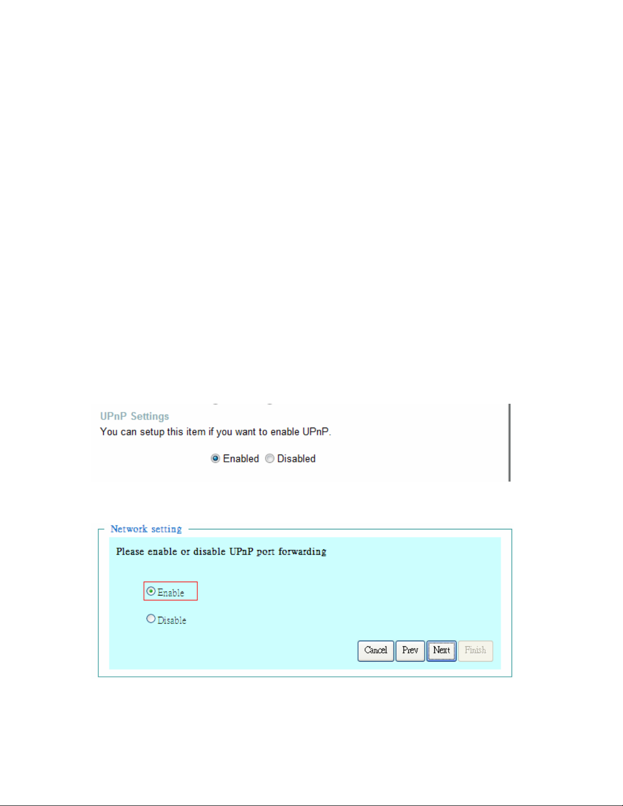
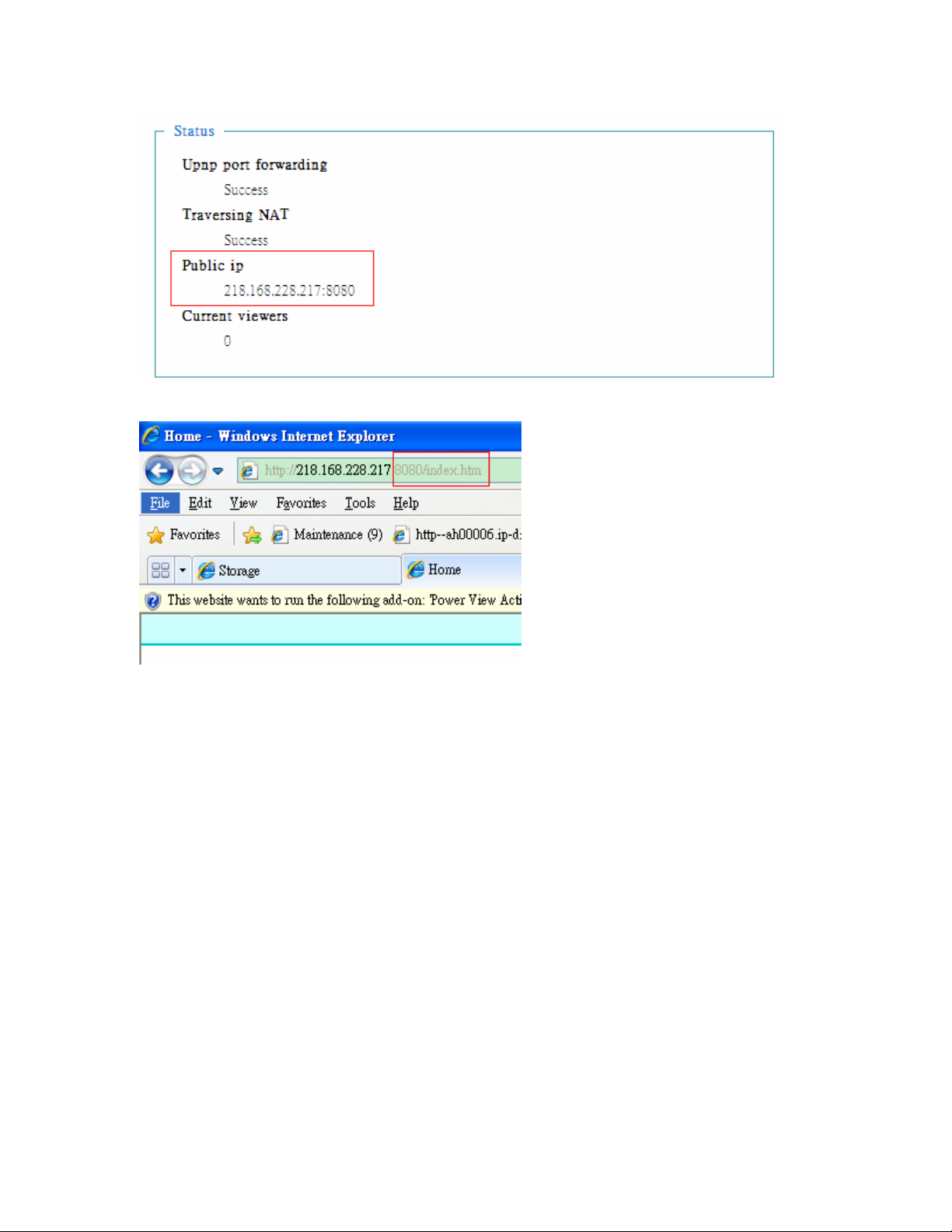
(1) By UPnP Port Forwarding
1.
Select an IP router. It must support UPnP port forwarding and enable this function
first!!
2. Connect camera RJ45 cable to IP router and the router is also connected to Internet.
3. Plug power cord to
4. Go to
camera Network page. Enable UPnP port forwarding
camera.
5. Check
56/62
camera status, we can see the ports had been successfully opened!
Page 57
Network Camera User’s Manual
6.Type IP address:8080 at browser. Then you can see
camera through Internet.
7.You can also type the ddns name at below label of
example, you may type ah00001.ip-discovery.com:8080.
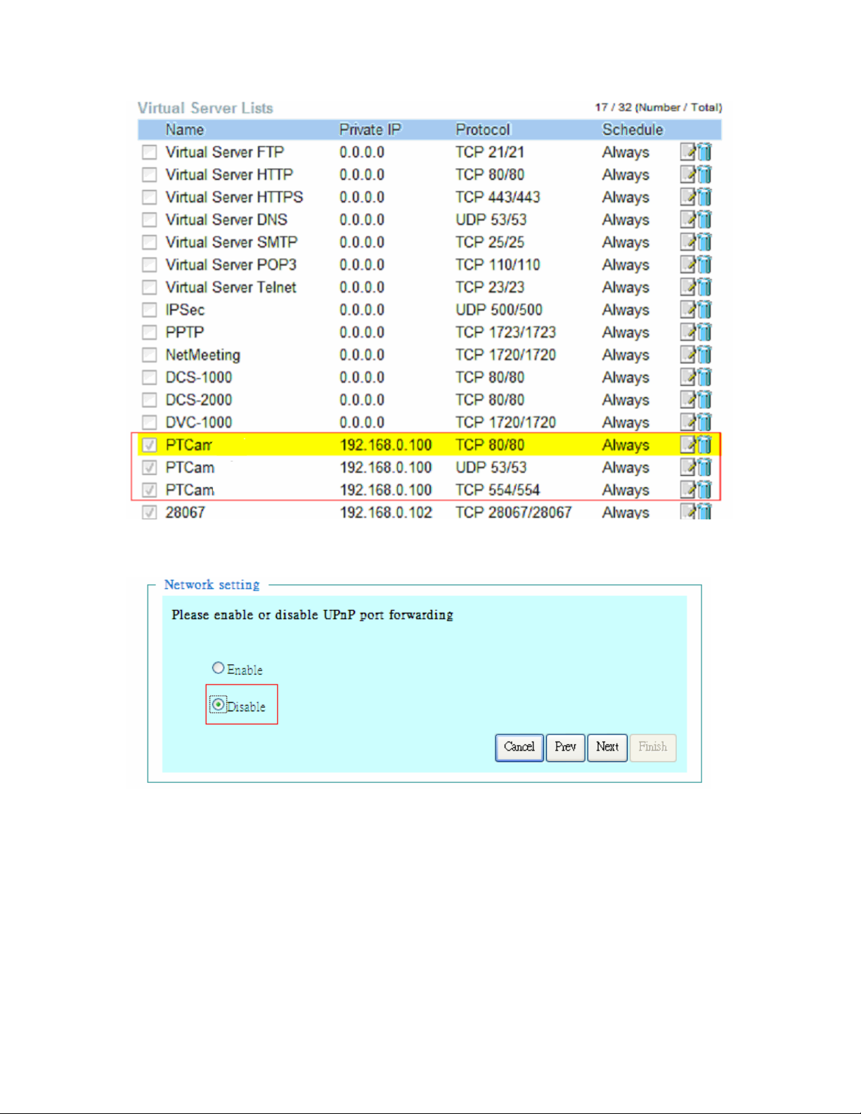
(2) By Setting Port Forwarding Manually
1. Select a router. Set the port forwarding as following.
camera on browser URL field. For
57/62
Page 58
Network Camera User’s Manual
PS. Port 80 is HTTP Port, port 53 is stream port, port 554 is RTSP port. and port 443 is
HTTPS port.
2.Go to
camera Network page. Disable UPnP port forwarding function.
58/62
Page 59
Network Camera User’s Manual
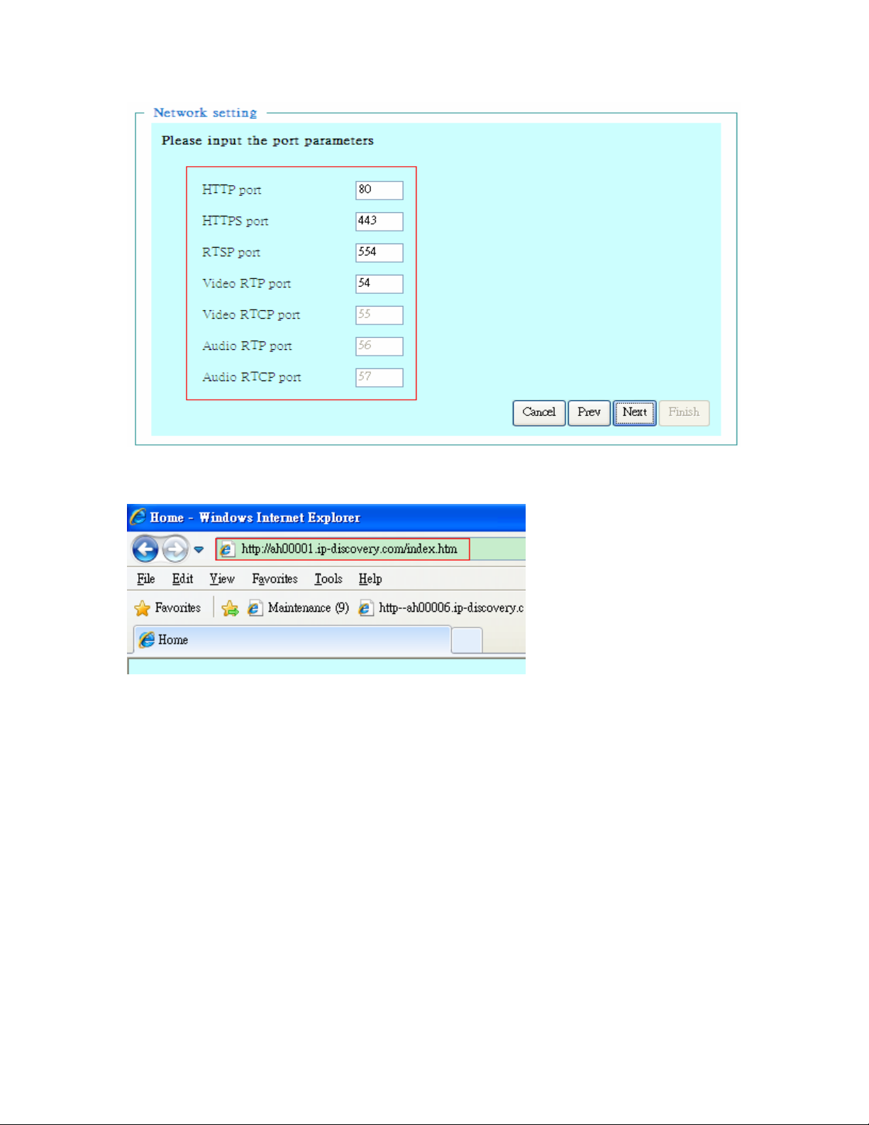
3. Type IP address at browser. Then you can see
4. You can also type the ddns name at below label of
example, you may type ah00001.ip-discovery.com.
camera through Internet.
camera on browser URL field. For
Note: The firewall software at PC may block the transfer of network camera.
Please remove or stop the kind software.
Q4: What is the default name and password of administrator?
A4: The name is “root” and password is the last six number of the MAC.
Q5: How can I find the network camera in the local area network?
A5: By using the IP Finder2 program or using UPnP to find it.
Q6: IP Finder2 program cannot find Network Camera in the local area
network at first time?
A6: Make sure the subnet of network camera is same as your PC. If the local area
network supports DHCP, the camera is “Get IP address automatically” in the “Network”
page default. If the local area network does not support DHCP, change your PC IP
address to “192.168.0.xxx”.
59/62
Page 60
Network Camera User’s Manual
Q7: How can I restore the network camera to default value?
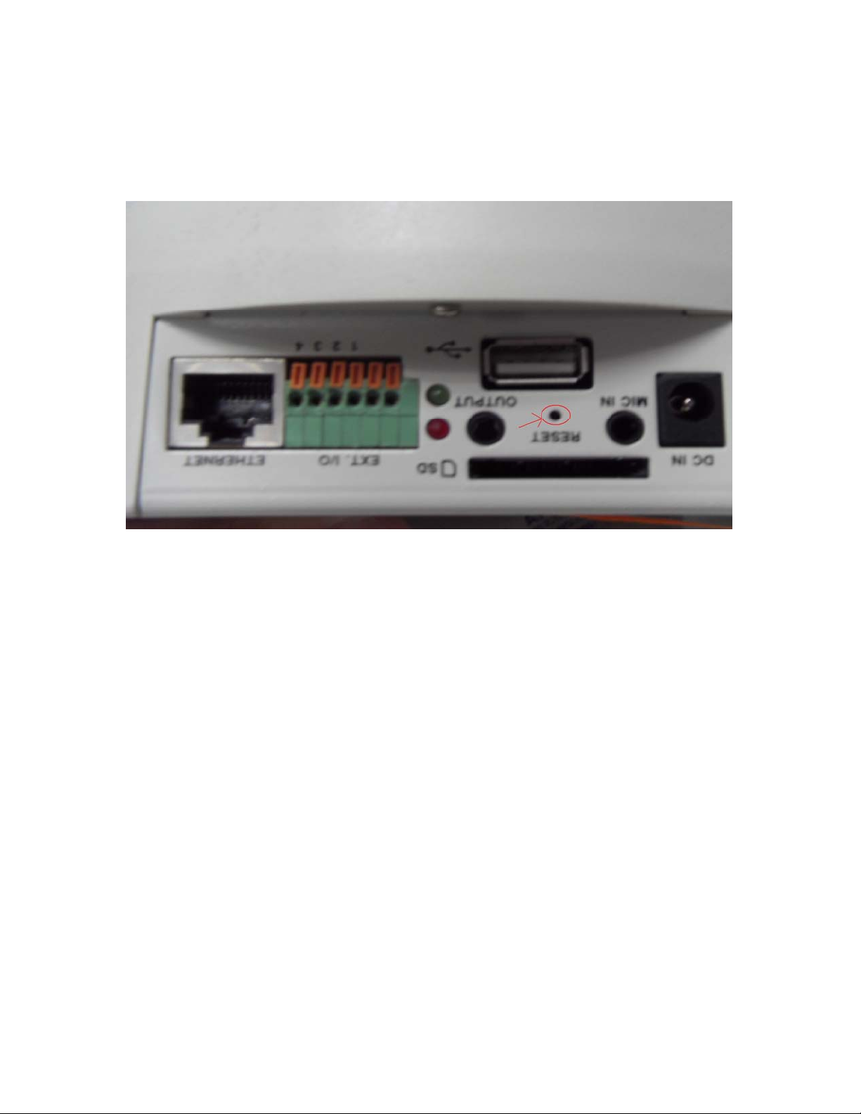
A7: Use a gem clip to press on the inside button until the led flashing. After three cycles
of the flashing, the network camera begins to restore default value. You can also press
the button “Factory” in “Maintenance” page to restore the default value.
Q8: I cannot play the recorded video file.
A8: Install the audio codec in the CD, and use the Windows Media Player 10 or later to
play the *.ASF or *.AVI file recorded by the network camera.
Q9: Infrared led does not light up?
A9: Check 「 Configuration>Audio and Video>Infrared LED Control 」 is “Auto” or
“Manual》Turn on”.
Q10: The network camera cannot focus accurately.
A10:
(1) The lens is dirty or dust is attached. Clean the lens with lens cleaner. And then adjust
the camera focus manually.
(2) The image may be out of focus. If the object is too near, move the object away from
Network Camera.
Q11: The cover of network camera is warm. Is it normal?
A11: Network camera is a precision device. The internal material has the operational
temperature, and it is normal when user touch the cover feels warm. It is recommended
to put the network camera at aired place, and not put at any other device.
Q12: The process of upgrade firmware abort.
A12: Contact your dealer for further help.
60/62
Page 61

Network Camera User’s Manual
Q13: Cannot access the login page and other web pages of Network
Camera from Internet Explorer
A13:
• May be due to the network cable. Try correcting your network cable and configuration.
Test the network interface by connecting a local computer to the Network Camera via a
crossover cable.
• Make sure the Internet connection and setting is ok.
• Make sure enter the IP address of Internet Explorer is correct. If Network Camera has
a dynamic address, it may have changed since you last checked it.
• Network congestion may prevent the web page appearing quickly. Wait for a while.
The IP address and Subnet Mask of the PC and Network Camera must be in the same
class of the private IP address on the LAN.
• Make sure the http port used by the Network Camera, default=80, is forward to the
Network Camera’s private IP address.
• The port number assigned in your Network Camera might not be available via Internet.
Check your ISP for available port.
• The proxy server may prevent you from connecting directly to Network Camera, set up
not to use the proxy server.
• Confirm that Default Gateway address is correct.
• The router needs Port Forwarding feature. Refer to your router's manual for details.
• Packet Filtering of the router may prohibit access from an external network. Refer to
your router's manual for details.
• Access Network Camera from the Internet with the global IP address of the router and
port number of Network Camera.
• Some routers reject the global IP address to access Network Camera on the same
LAN. Access with the private IP address and correct port number of Network Camera.
• When you use DDNS, you need to set Default Gateway and DNS server address.
• If it’s not working after above procedure, reset Network Camera to default setting and
installed it again.
• Maybe the IP Address of the Network Camera is already being used by another device
or computer.
• If the problem is not solved, the Network Camera might be faulty. Contact your dealer
for further help.
61/62
Page 62

Network Camera User’s Manual
B. Technical specifications
- System
RAM: 4GB DDR
ROM: 16MB flash ROM
- IR Led
Auto/Manual mode, 10~12 M visible
Daylight sensor, angle +/-65, wave length
400~700nm
Spectral band width 42nm, Peak emission
wavelength
850nm
- Protocol
TCP/IP, HTTP, SMTP, FTP, DDNS, UPnP,
Telnet, NTP,
PPPoE, DNS, DHCP and RTSP
- Algorithm supported
H.264/MPEG4/MJPEG multi-codec for
streaming video
JPEG for still image
- Camera specification
1/2.7 inch color CMOS sensor, Resolution:
1920x1080
1.0Lux/F2.0
AGC, AWB, AEC
- Lens
Fixed focal with fine tuning, 4.0mm, F2.0
View angle 62 degree
- Video Resolution
Up to 30 frames at 1920*1080, 1280x1024
1280x800, 640x480, 320x240 and
176x144
- Audio
AMR/AAC
- Pan/Tilt speed
Pan speed: 1~200°/Sec
Tilt speed: 1~120°/Sec
Support multi - direction movement
-Physical
10 baseT or 100 baseT Fast Ethernet auto
negotiation
- EMI & Safety
CE, FCC
- Operating Environment
Temperature: 0 - 40℃
Humidity: 85% RH
- Pan/Tilt angle
Pan: 390°(-195°~195°)±1°
Tilt: 95°(-5°~ 90°)±1°
Accuracy: ±0.25°
- Power
Input: 100-240VAC, 50/60Hz, 0.7A
Output: 12VDC, 1.5A
Consumption: Max 12 W
Support 802.3af compliant Power over
Ethernet
- Dimension
Height: 128mm
Diameter: 130mm
- Weight
NET. 950g
62/62
 Loading...