

Page 1
R-MI-FAXL1 Rev.: 0 english version
Series FLOMAT
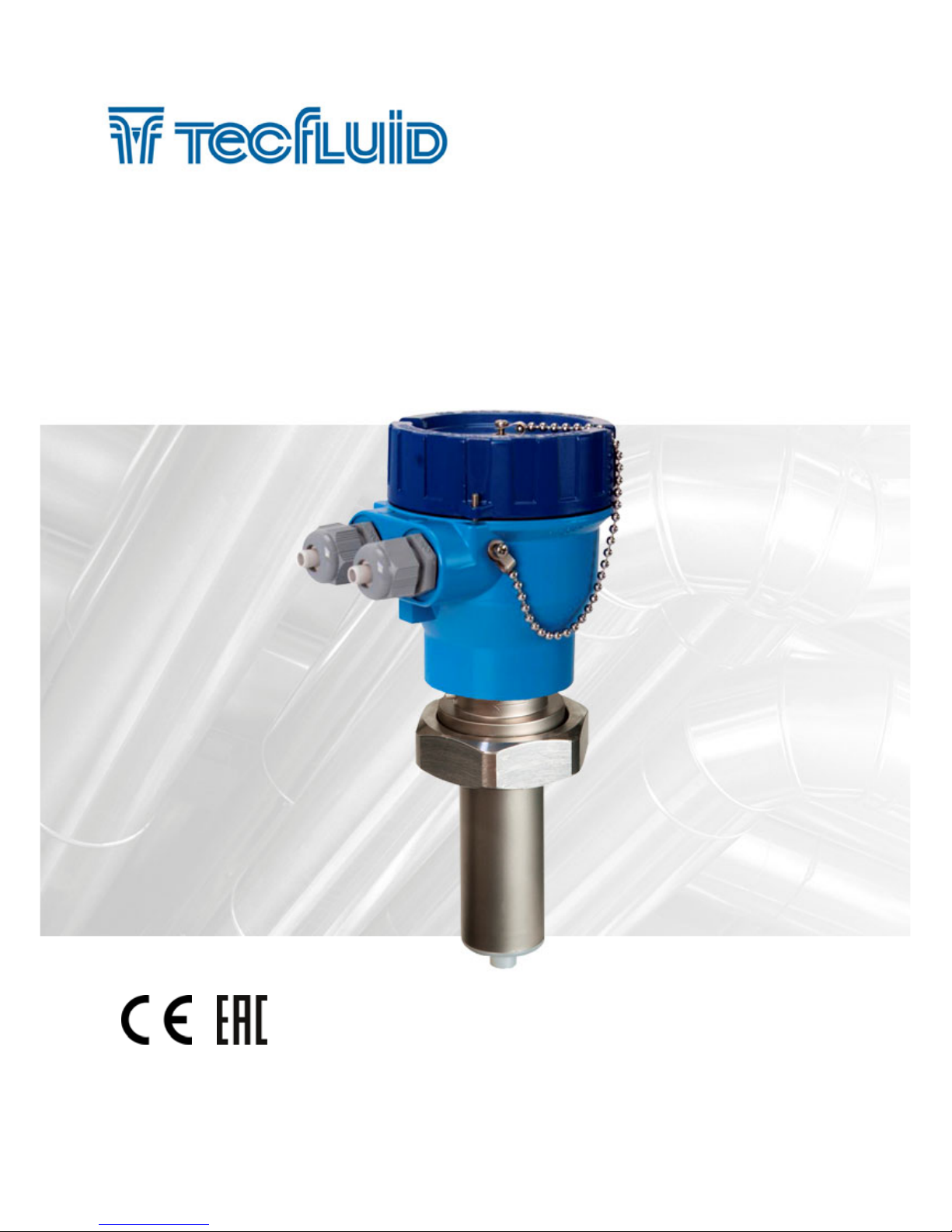
Sensor FLOMAT-XL + Converter XL1
Instructions manual
The art of measuring
Page 2

2
Thank you for choosing a product from Tecfluid S.A.
This instruction manual allows the installation, configuration,
programming and maintenance. It is recommended to read it before
using the equipment.
This document shall not be copied or disclosed in whole or in any
part by any means, without the written permission of Tecfluid S.A.
Tecfluid S.A. reserve the right to make changes as deemed
necessary at any time and without notice, in order to improve the
quality and safety, with no obligation to update this manual.
Make sure this manual goes to the end user.
Keep this manual in a place where you can find it when you need
it.
In case of loss, ask for a new manual or download it directly from
our website www.tecfluid.com Downloads section.
Any deviation from the procedures described in this instruction
manual, may cause user safety risks, damage of the unit or cause
errors in the equipment performance.
Do not modify the equipment without permission. Tecfluid S.A. are
not responsible for any problems caused by a change not
allowed. If you need to modify the equipment for any reason,
please contact us in advance.
PREFACE
WARNINGS
Page 3

3
TABLE OF CONTENTS
SERIES FLOMAT
1 INTRODUCTION ........................................................................... 5
2 RECEPTION ................................................................................. 6
2.1 Unpacking .......................................................................... 6
2.2 Storage temperatures ......................................................... 6
3 HANDLING ................................................................................... 6
4 INSTALLATION ............................................................................. 6
4.1 Straight pipe sections ......................................................... 6
4.1.1 Mixtures ................................................................ 8
4.2 Sensor position .................................................................. 8
4.3 Valves ............................................................................... 8
4.4 Pumps ................................................................................ 9
4.5 Aeration ............................................................................. 9
4.6 Vibrations ........................................................................... 10
4.7 Magnetic fields .................................................................. 10
4.8 Temperature ...................................................................... 10
5 MOUNTING .................................................................................. 11
5.1 Pipe adaptor mounting ....................................................... 11
5.2 Sensor mounting ................................................................ 13
5.3 Tightening torque ................................................................ 13
5.4 Electronic converter connection .......................................... 13
5.5 Electronic converter programming ........................................ 13
6 ELECTRICAL CONNECTION ........................................................... 14
6.1 Power supply wiring ............................................................ 14
6.2 Analog output wiring ........................................................... 15
6.3 Digital output wiring ............................................................ 16
7 ASSOCIATED SOFTWARE WINSMETER XL1 ................................. 18
7.1 USB cable connection and software installation ................... 18
7.2 Port connection ................................................................... 19
Page 4

4
7.3 Password ........................................................................... 20
7.4 Access to “Installation” ....................................................... 24
7.4.1 Sensor .................................................................. 24
7.4.2 Power supply ......................................................... 24
7.5 Access to “Programming” ................................................... 25
7.5.1 Current loop .......................................................... 25
7.5.2 Units ....................................................................... 26
7.5.3 Digital output ......................................................... 26
7.5.4 Current loop calibration .......................................... 26
7.6 Visualization ....................................................................... 27
7.7 Zero flow drift adjustment .................................................... 27
7.8 Datalogger ......................................................................... 28
7.9 Firmware updates ............................................................... 29
7.10 Configuration file ................................................................. 30
8 MAINTENANCE ............................................................................ 31
9 TECHNICAL CHARACTERISTICS ................................................... 32
10 SAFETY INSTRUCTIONS ............................................................... 33
10.1 Pressure equipment directive .............................................. 33
10.2 Certificate of conformity TR CU (EAC marking) ..................... 33
11 DIMENSIONS ............................................................................... 34
12 TROUBLESHOOTING .................................................................... 37
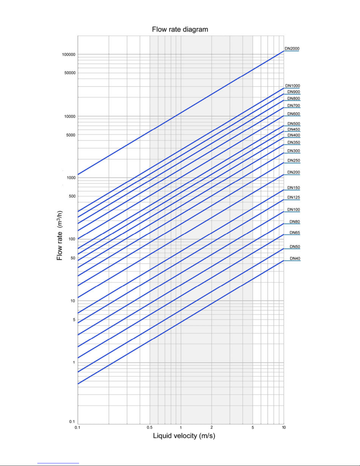
ANNEX Flow rate diagram ................................................................... 38
Page 5
5
1 INTRODUCTION
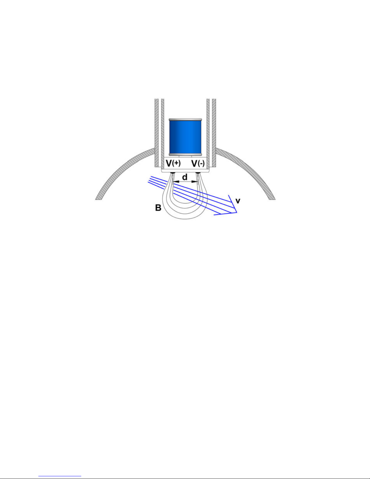
The FLOMAT electromagnetic flowmeters are based on Faraday’s induction law.
When an electrically conductive liquid flows through a magnetic field, perpendicular to the
flow direction, it induces a voltage V proportional to the liquid velocity.
Two electrodes in contact with the liquid and positioned perpendicularly to the magnetic
field, sense this voltage V.
The electronic converter is based on the most advanced technology in digital signal
processing, in order to obtain accurate and reliable measurements.
The device provides the following features:
Coil excitation by means of pulsed signal to obtain a negligible zero offset.
Pulse and current output proportional to the flow rate and user programmable.
V = B·v·d
Where:
V = Measured voltage in the electrodes
B = Magnetic field
v = Liquid velocity
d = Distance between electrodes
Page 6

6
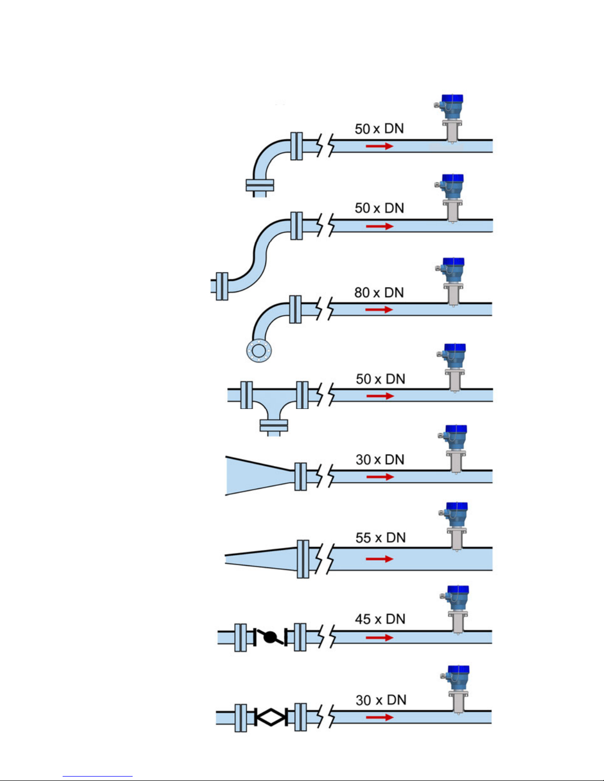
4.1 Straight pipe sections
The point where the FLOMAT sensor will be installed must be a straight pipe section,
separated from elements that can disturb the flow profile, such as elbows, diameter
changes, etc. Depending on the element the minimum necessary distances upstream from
the sensor are shown on the next page (BS 1042-2.2:1983 standard):
2 RECEPTION
The FLOMAT electromagnetic flowmeters with XL1 converter are supplied conveniently
packaged for transportation together with their instruction manual for installation and
operation.
All the flowmeters have been verified in our calibration rigs to obtain the gain factor for each
sensor.
2.1 Unpacking
Unpack the instrument carefully, removing any remains of the packing.
2.2 Storage temperatures
-20ºC ...... +60ºC
3 HANDLING
It should always be done with care and without knocks.
4 INSTALLATION
This should be made in a straight pipe run that guarantees that the pipe is always completely
full.
Avoid high points of the pipes where air pockets usually form, or pipes with downwards
flow where vacuums can occur.
Partially full pipes can involve important reading errors.
Flow rate measurement with open discharge makes it necessary to install the flowmeter in a
pipe section with a siphon which avoids stagnation of air in the sensor.
Page 7
7
Disturbing element
upstream the
sensor
Minimum distance between
the sensor and the element
Several 90º
coplanar bends
Fully opened plug
valve
Fully opened
butterfly valve
90º elbow
Several 90º non-
coplanar bends
T accessory
Total angle
convergent 18 to 36°
Total angle
divergent 14 to 28°
Page 8
8
4.2 Sensor position
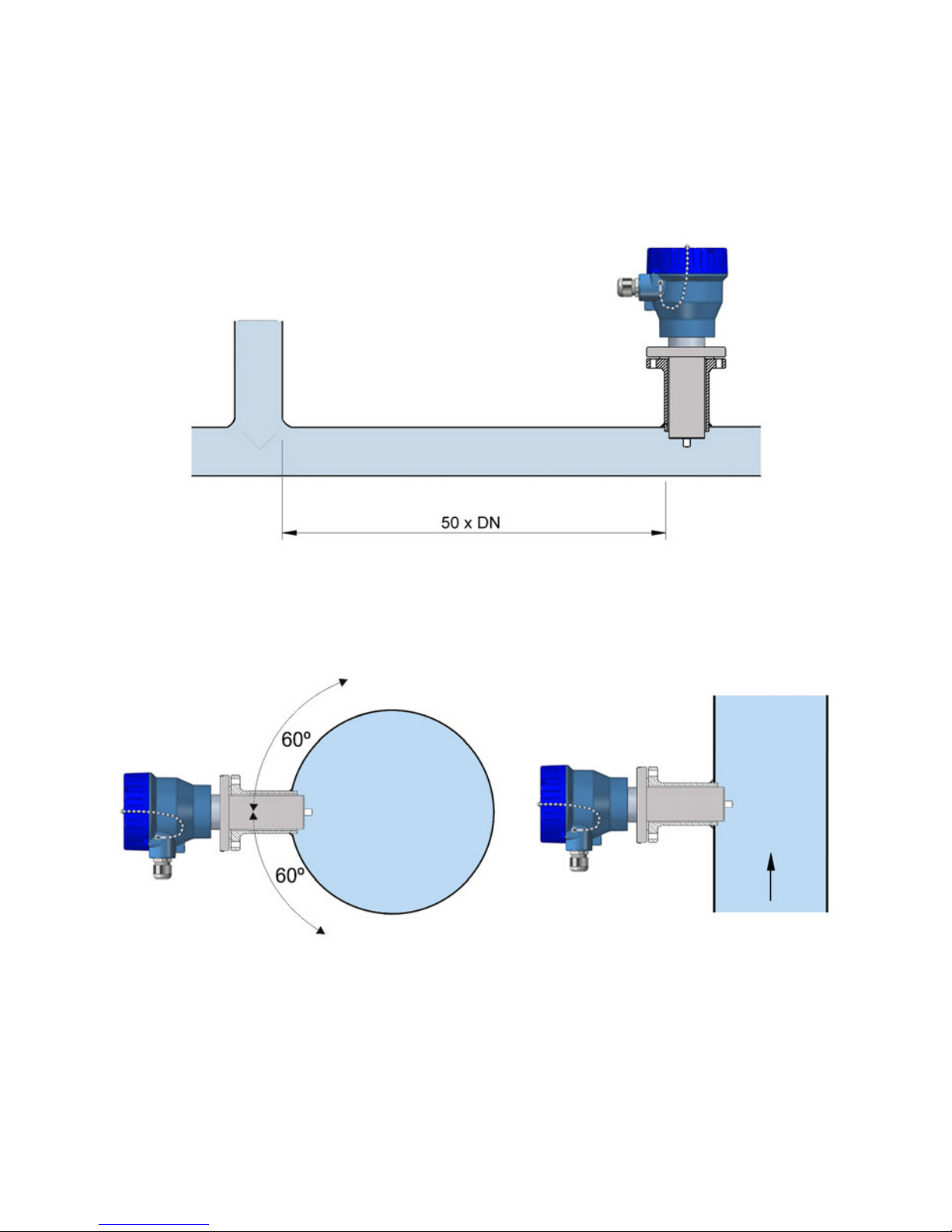
The optimum position to install the sensor is with the electrodes in the side of the pipe. This
way, air pockets at the top of the pipe are avoided.
Downstream, the minimum recommended distance to a disturbing element is 5 x DN.
4.1.1 Mixtures
If liquids of different conductivities are mixed it is necessary to install the sensor a minimum
of 50 x DN from the point of mixture in order to obtain a uniform conductivity of the liquid
and stabilize the readings.
If this distance is shorter, readings may be unstable.
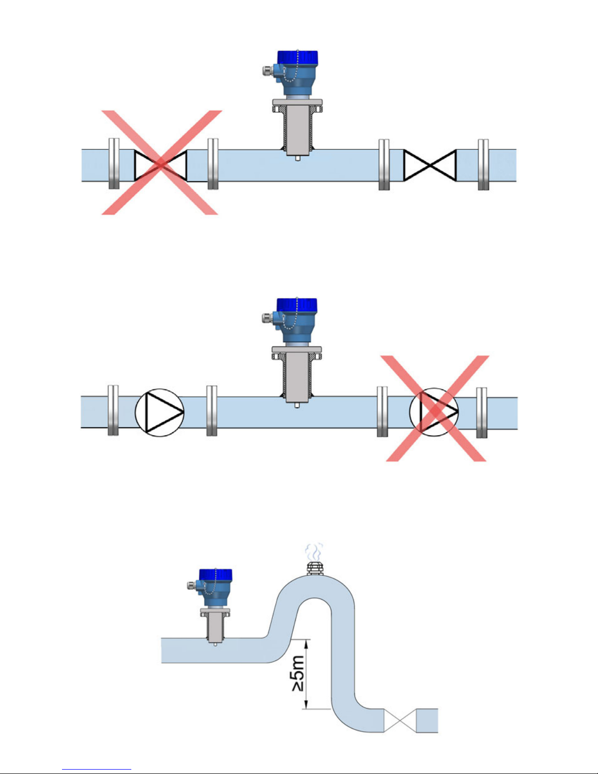
4.3 Valves
Control valves or shut-off valves should always be installed downstream from the sensor to
assure that the pipe is always full of liquid.
Page 9
9
4.5 Aeration
If there is a point where the difference in level is higher than 5 m an air inlet valve should be
installed after the sensor to avoid a vacuum effect that could damage the sensor.
4.4 Pumps
Pumps should be mounted upstream from the sensor to avoid the suction of the pump
(vacuum).
Page 10
10
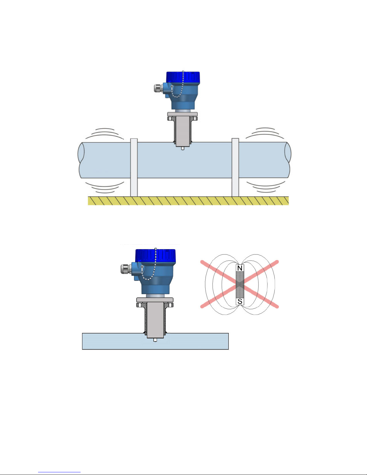
4.6 Vibrations
Vibrations of the pipes should be avoided by anchoring the pipe before and after the sensor.
The vibration level should be less than 2.2 g in the range of 20 -150 Hz according to IEC 068
-2-34.
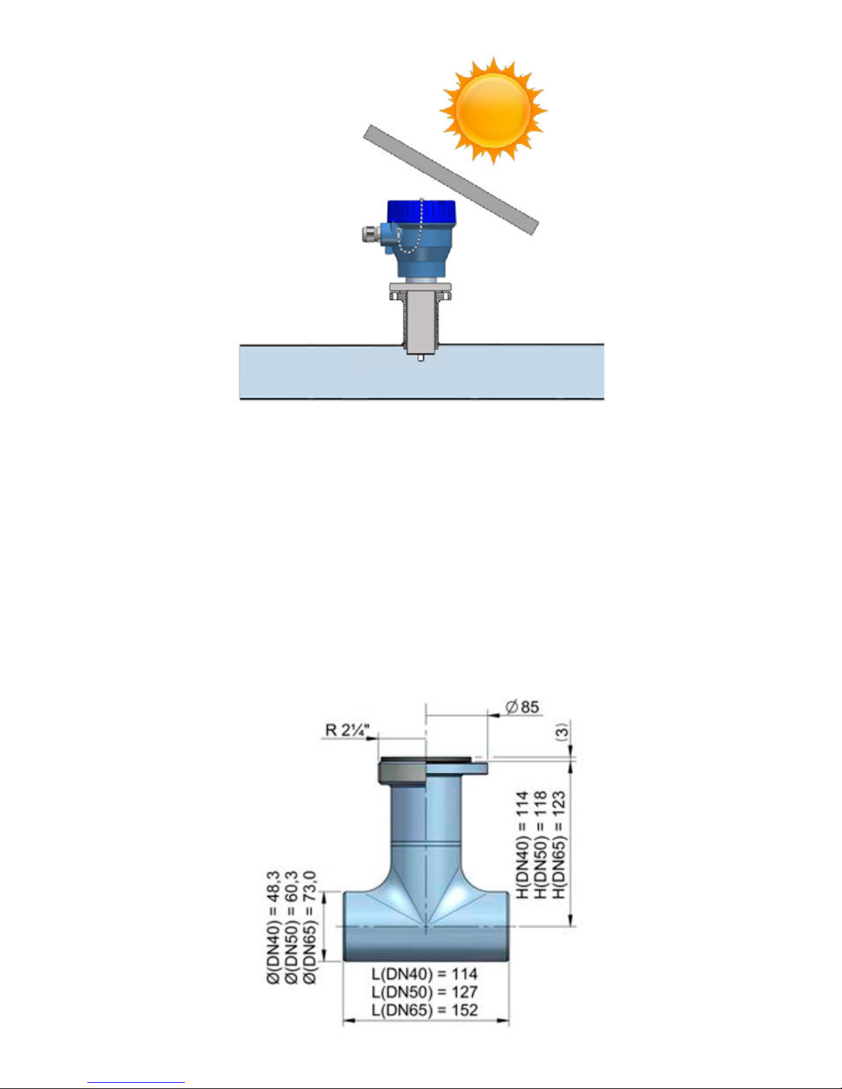
4.8 Temperature
In open air installations it is recommended to install a protection to avoid direct sun light on
the flowmeter.
4.7 Magnetic fields
Strong magnetic fields close to the sensor should be avoided.
Page 11
11
With thermally insulated pipes DO NOT insulate the sensor. High temperatures can damage
it.
The maximum liquid temperatures are shown on page 32.
5 MOUNTING
5.1 Pipe adaptor mounting
The sensor is normally supplied mounted in its pipe adaptor. Before welding the adaptor to
the pipe, the sensor must be removed to avoid irreparable damage due to excessive
temperatures.
There are two basic types of pipe adaptors: with threaded or with flanged connection.
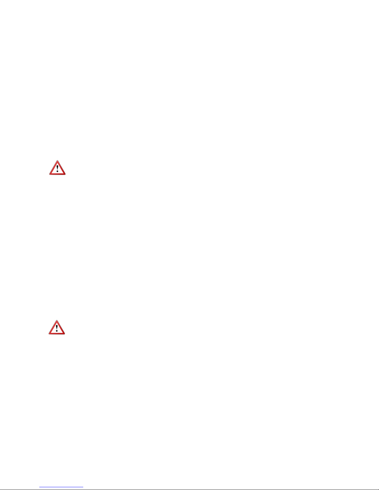
For the smallest pipe diameters (DN40, 50 & 65) the pipe adaptor is supplied welded to a
short length of pipe with a “T” form. For this type just couple it to the pipe by welding or
gluing in the case of PVC, PP, PE or other plastics.
Page 12

12
For DN80 and bigger, there are three lengths for each of the two types of fittings.
The process of putting the pipe adaptor in should be done accurately. The distance (H) (see
drawings on next page) which is what the pipe adaptor should protrude above the surface of
the pipe is important.
As shown in the table on the next page, to know the distance, the thickness of the pipe s
must be known.
In order to make the positioning of the pipe adaptor in the pipe easier, there is a label on one
of its sides with markings indicating the position of the internal pipe diameter for each DN.
Cut this label above the line corresponding to the DN of the pipe, at a distance equal to the
pipe thickness. Peel off the bottom part of the label. Once the pipe adaptor is placed into its
final position, where the label was cut must coincide with the outer diameter of the pipe.
This ensures that the measuring electrodes penetrate far enough in the area of flow profile
that will allow an accurate measurement.
DN C (mm)
Insert pipe adaptor
L (mm) H (mm)
80 10
93
88-s
100 12,5 85,5-s
125 15,5 82,5-s
150 19 79-s
200 25 73-s
250 31 67-s
300 37,5 60,5-s
350 44 54-s
400 50 48-s
500 62,5
145
140,5-s
600 75 128-s
700 87,5 115,5-s
800 100 103-s
900 112,5 90,5-s
1000 125 78-s
1200 150 203-s
1400 175 178-s
1600 200 153-s
1800 225 128-s
2000 250 103-s
205
Page 13
13
Example:
Suppose a pipe of 300 mm inner diameter (DN300) and 5.5 mm thick. In the chart we can
see that the distance that the pipe adaptor must extend above the external wall is H = 60.5 s = 60.5 - 5.5 = 55 mm.
The values in the chart are calculated considering the gasket supplied with the instrument,
which is 3 mm thick. If the thickness of the gasket is changed, the value of H will change.
The equation to calculate H’ for a gasket of thickness d is the following:
H’ = H + 3 - d
In the previous example, if the gasket was 5 mm thick, the distance that the adaptor should
extend above the external wall would be H’ = 55 + 3 - 5 = 53 mm.
Drill a 48.5 mm diameter hole in the pipe to insert the pipe adaptor and weld the fitting to the
pipe.
If the pipe is made of concrete or other material to which the pipe adaptor cannot be
welded, a clamp-on accessory or saddle should be used. In this case, please contact us to
inform about the suitable sensor length.
The axis of the pipe adaptor should be perfectly perpendicular to the pipe axis.
5.2 Sensor mounting
Once the pipe adaptor is mounted, place the flat seal in its position and install the sensor
with the arrow pointing in the flow direction. The electrodes must be perfectly perpendicular
to the pipe axis.
In order to align the sensor, the two bolts or pins situated in each side of the cylinder in the
top of the FLOMAT sensor must be aligned with the axis of the pipe and the arrow pointing
in the flow direction.
5.3 Tightening torque
The tightening torque for the flange screws should not exceed 7.1 Nm.
The tightening torque for the threaded fitting should not exceed 21 Nm.
5.4 Electronic converter connection
See point 6.1 on page 14.
5.5 Electronic converter programming
FLOMAT sensor is insertion type, so it can be installed in pipes with different diameters.
NOTE: It is essential to program the internal diameter of the pipe, in order that the
converter can indicate the correct flow rate.
Programming of the pipe diameter is done by means of the software Winsmeter XL1 as
indicated in point 7.4.1 on page 24.
Page 14
14
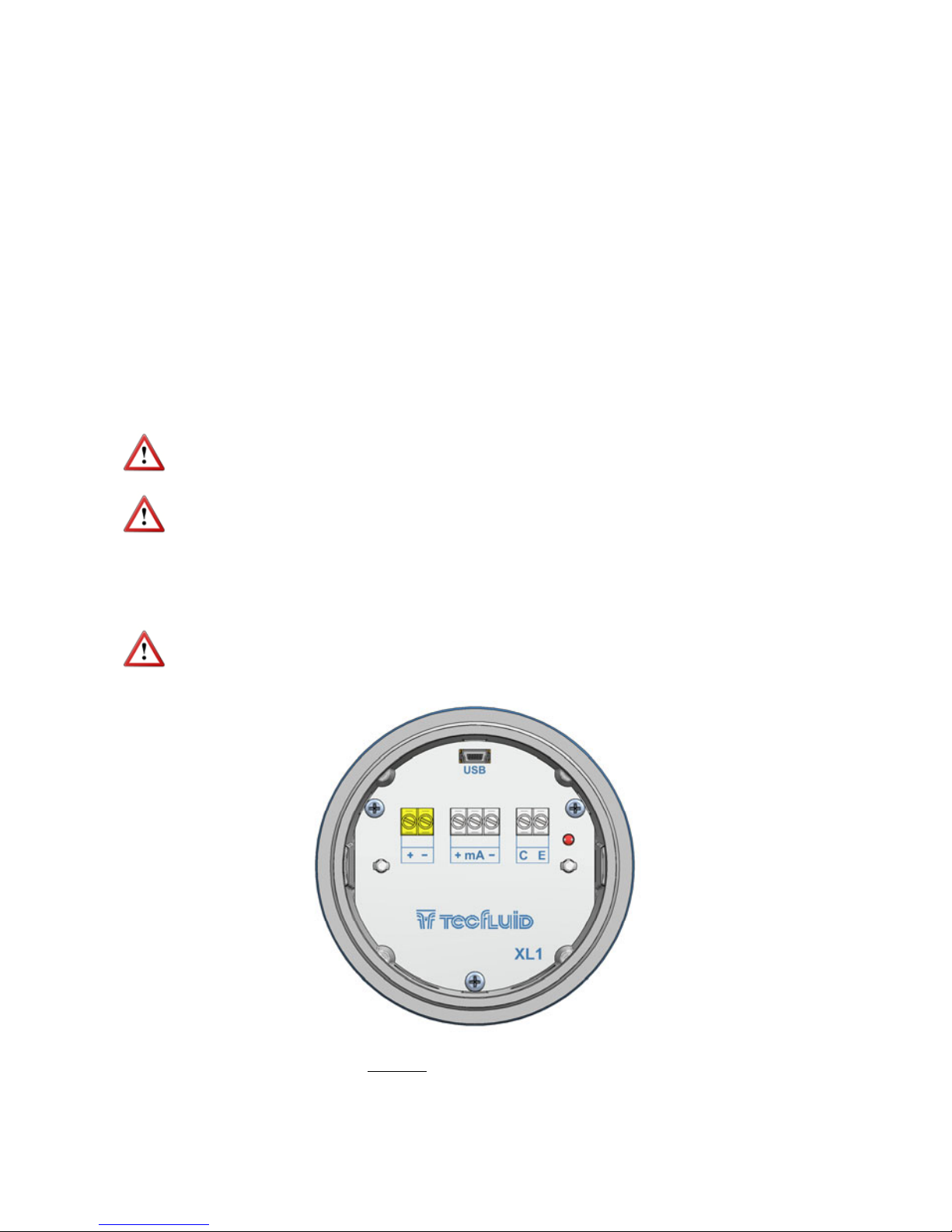
6 ELECTRICAL CONNECTION
For the electrical connection, the FLOMAT flowmeter with XL1 converter is provided of
terminal strips. To help in the wiring of the equipment, the description of the terminals is
marked next to each terminal strip.
For the electrical installation it is recommended to use multiple conductor cables with
individual cable sections in the order of 0.25 to 0.5 mm
2
in order to make it easier to
connect.
Before starting the installation, check that the cable glands are the right size for the cables to
be used. This will guarantee the instrument will stay watertight. The cable glands used are
for cables with outside diameters between 5 mm and 12 mm.
It is better to maintain the cables with mains voltage (power supply) separated from the
cables with low level signals (4-20 mA or pulses).
To connect the cables, peel the outside insulation to free the inner cables. Then pass the
cables through the cable glands and screw down in the corresponding positions of the
terminal strip as indicated in the following point.
Grip carefully the cables with the cable glands to maintain the degree of protection.
Incorrect installation of the cable gland or inadequate cable placement can cause irreparable
damage to the converter.
IMPORTANT NOTE: To ensure smooth operation of the equipment, it is recommended
to make the electrical connection according to the following points:
For output signals, use shielded cable when possible.
Keep wires away from strong sources of noise.
6.1 Power supply wiring
Before starting the installation of the equipment, check that the supply voltage available is
the same as marked on the label of the flowmeter.
Terminal
+ Power supply positive
- Power supply negative
Page 15
15
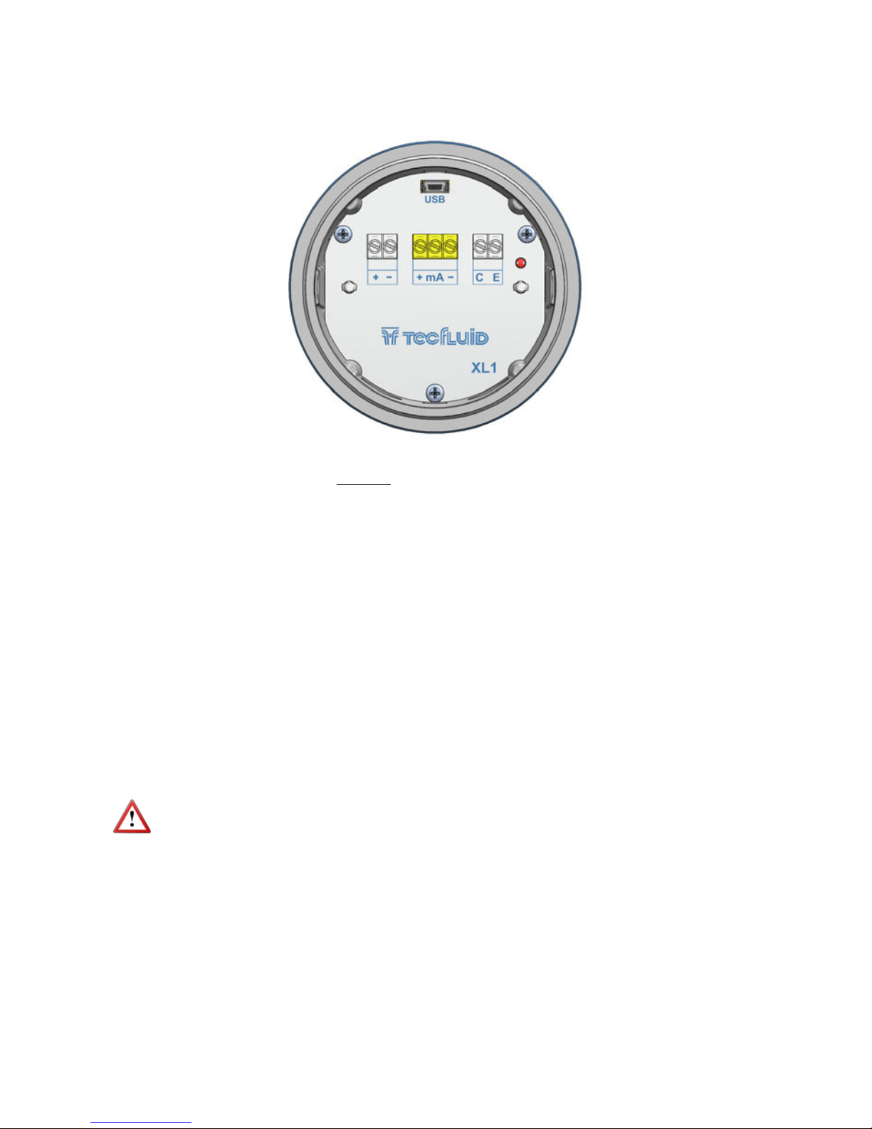
When the device is powered, the led will be on.
6.2 Analog output wiring
Terminal
+ mA (positive, active output)
mA mA
- mA (negative, passive output)
The analog output is a current loop working linearly between 4 and 20 mA and proportional
to flow rate. When the converter detects empty pipe, the current loop gives a value of 3.6
mA, and when the flow rate is negative and the current output is configured as
unidirectional (see point 7.5.1), the loop will give 21 mA.
The analog output is galvanically isolated. It can be either active (which means that the
receiving device must be passive) or passive (which means that the receiver must supply the
power for the current loop). It is recommended to use a receptor with an input resistance of
less than 700 Ω to guarantee correct operation.
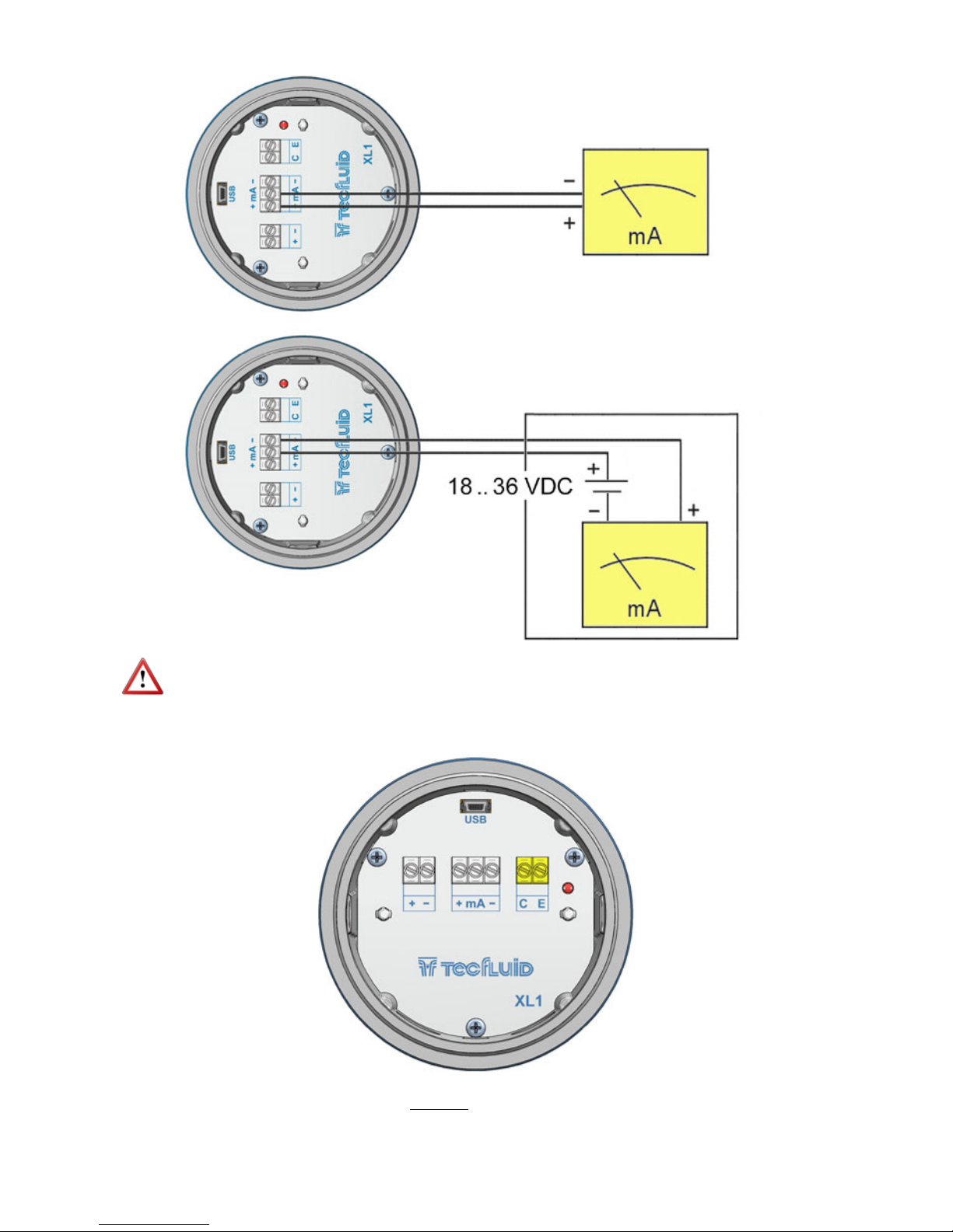
The configuration of the analog output mode (active or passive) is done by means of the
connection to the terminal strip. For active mode, terminals “+” and “mA” are connected. For
passive mode, terminals “mA” and “-” are connected.
NOTE: The analog output has protection against reversed polarity. Due to another
protection against over voltages, if a loop supply voltage of more than 32 V is connected the
converter may be damaged.
Page 16
16
NOTE: Never connect the load between entre terminals “+” and “–”. The analog output
could be damaged.
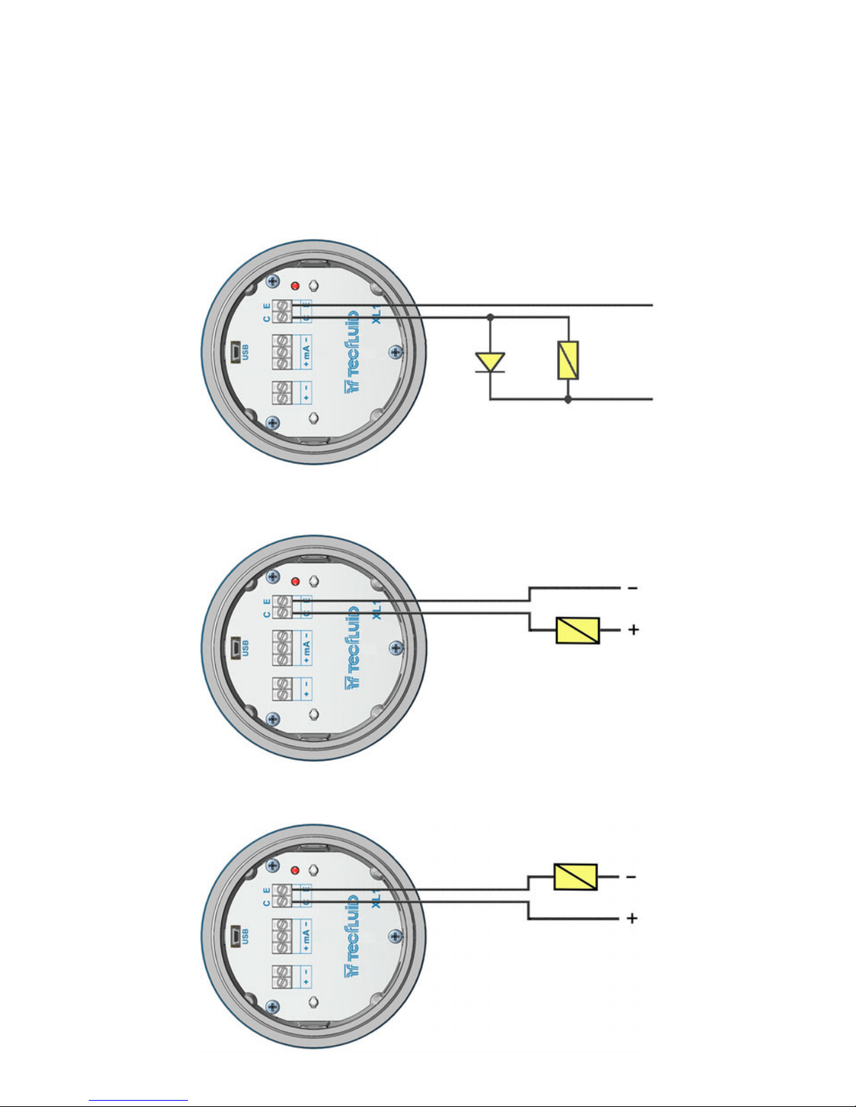
6.3 Digital output wiring
Terminal
C Collector
E Emitter
Active output
Passive output
Page 17
17
The digital output is opto-isolated. The terminals are the collector and emitter of a NPN
bipolar transistor.
If the equipment is configured as pulse mode (see page 26), the led will alternate between
green and red if there is a flow, and will remain green if there is no flow.
If it is configured as alarm mode (see page 26), the led will light red when the alarm is
activated and green when it is not.
In the case of using inductive loads, in order to protect the output transistor, the use of free
wheeling diodes is required.
Example. Connection with the load at the collector
Example. Connection with the load at the emitter
Coil
Page 18
18
7 ASSOCIATED SOFTWARE WINSMETER XL1
By means of this associated software, calibration and adjustment of the instrument can be
done in a comfortable and intuitive way.
Such software can be downloaded from the “Downloads” section of the Tecfluid S.A.
website www.tecfluid.com/downloads
7.1 USB cable connection and software installation
Extract the files from the Winsmeter XL1.zip to a new system folder.
Execute the Setup.exe file and follow the steps for the installation.
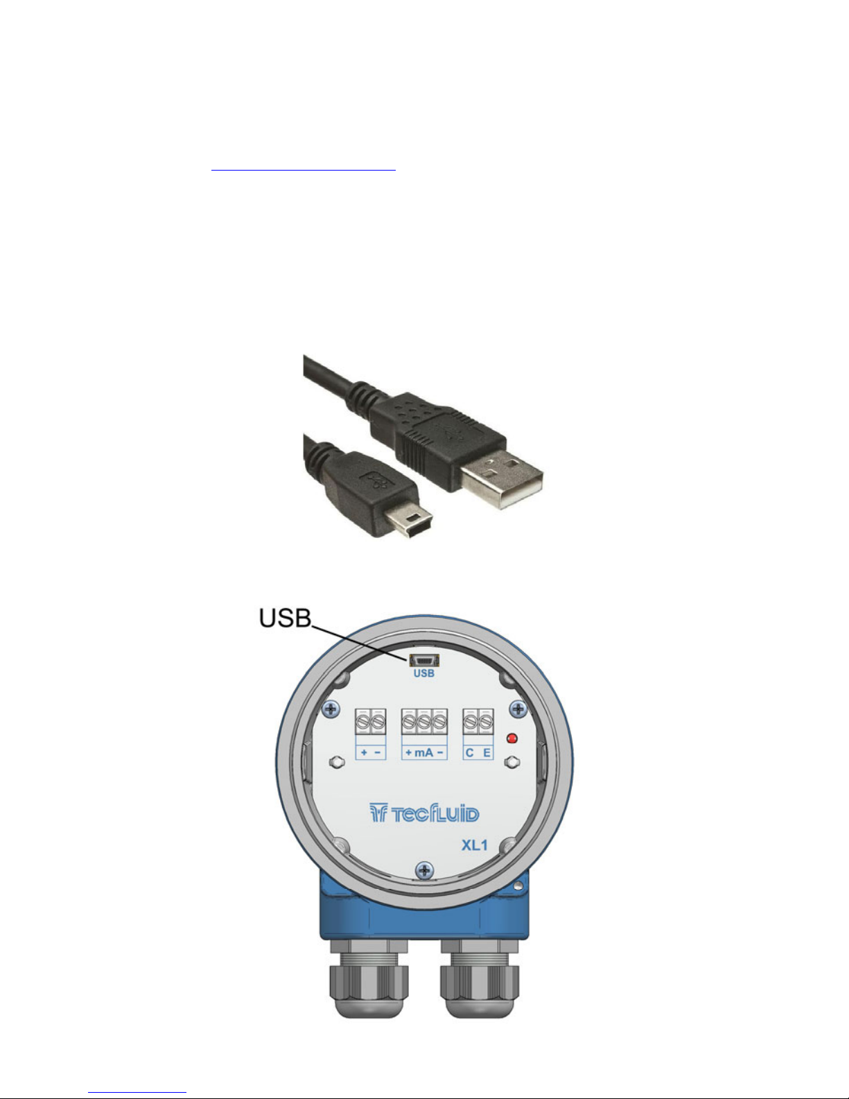
In order to connect the converter to a computer an USB cable is required. This cable is type A
at one end and mini USB type B at the other, and it is readily available on the market.
The ends of the cables can be seen in the picture.
The USB connector is located at the opposite side of the cable glands.
Page 19
19
7.2 Port connection
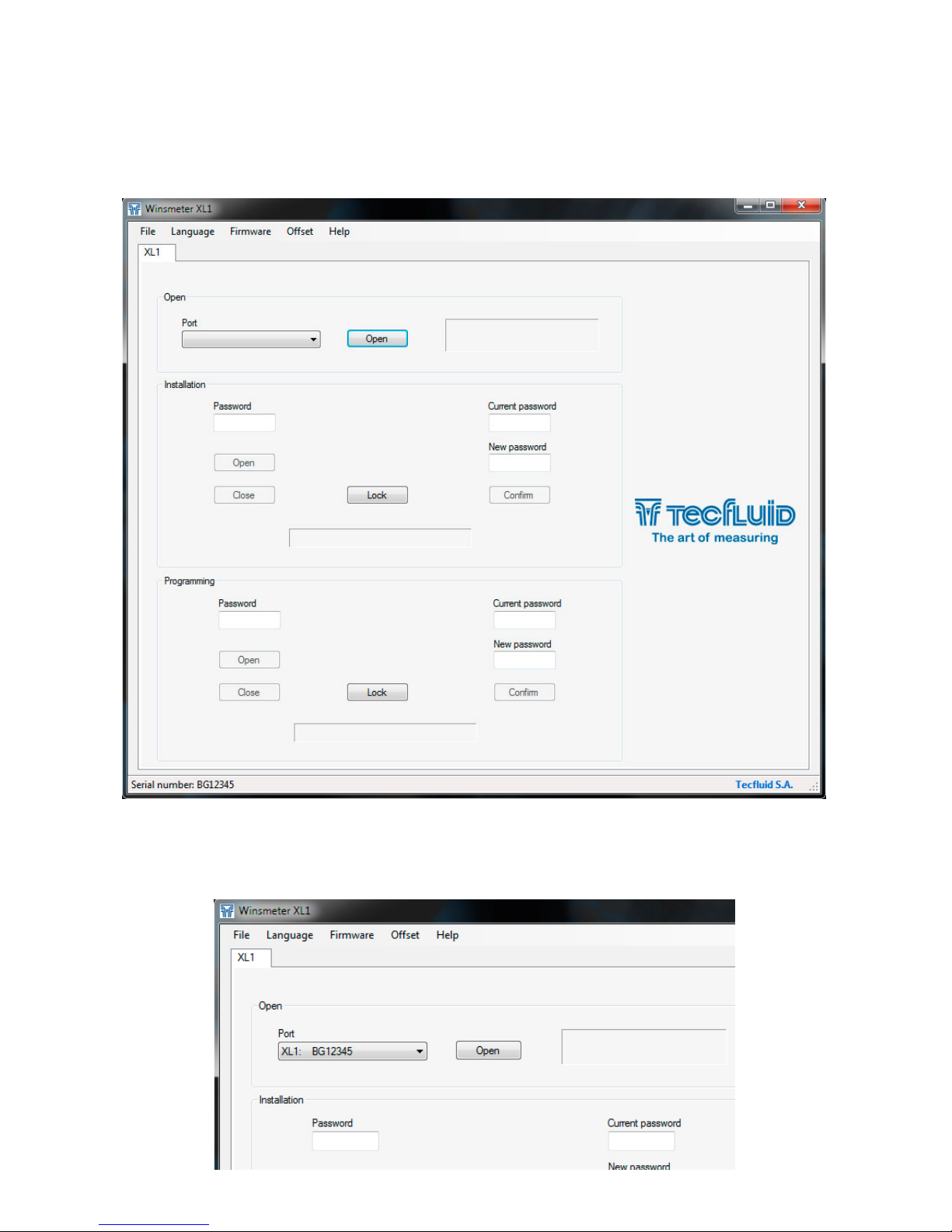
In the "Port" section, choose the appropriate port for the converter. This will appear with the
name of the port followed by XL1 and its serial number. Then click "Open".
Connect the USB cable at one end to the converter and at the other to the computer where the
software is installed.
Power on the electronic converter.
Execute the program WinsmeterXL1 following the sequence Start – Programs – Tecfluid S.A. WinsmeterXL1.
Page 20
20
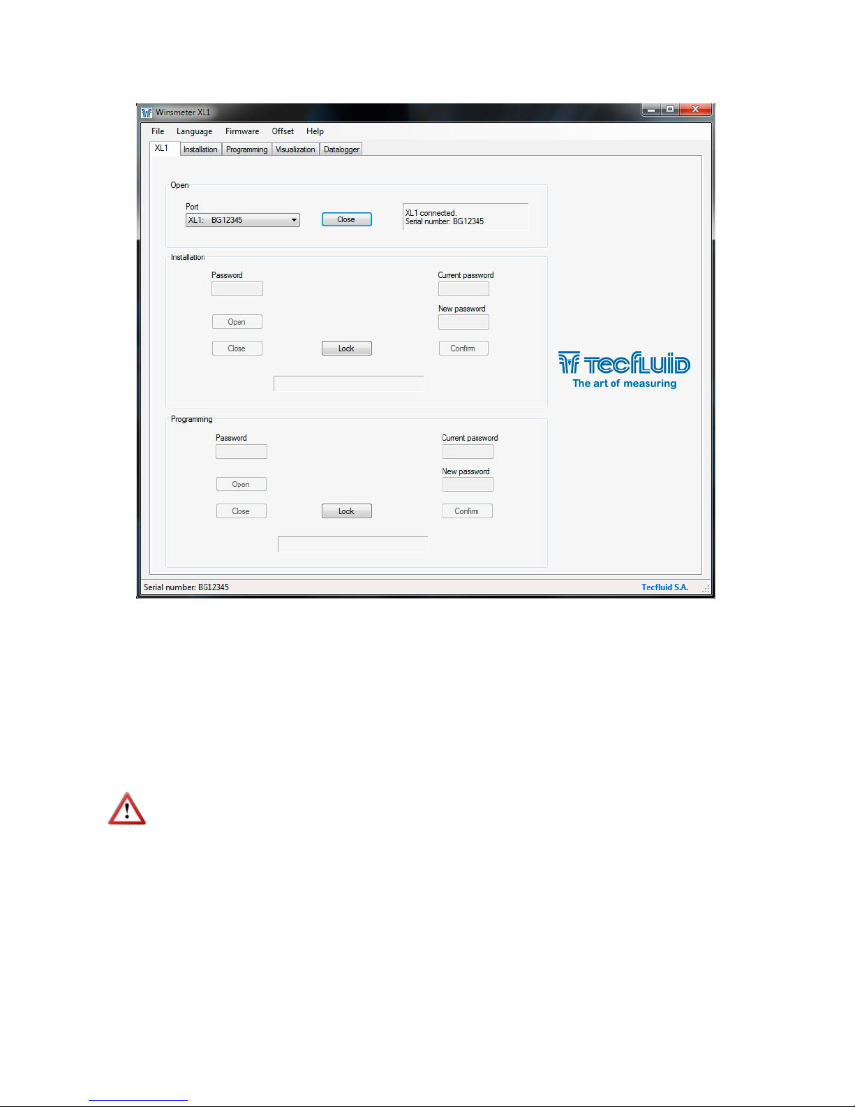
Once the port is open, the button "Lock" is activated.
7.3 Password
The XL1 converter can be locked so that programming data can be modified only with previous
password access.
When the converter is locked, data can be read but not modified.
By default the device is unlocked. All data can be modified by means of the program
Winsmeter XL1.
To set a password access to a section (“Installation” or “Programming”), the section must be
unlocked. To do this, simply press the “Lock” button in the desired section.
Each section can be locked or unlocked independently. Passwords are equally independent for
each section.
Page 21
21
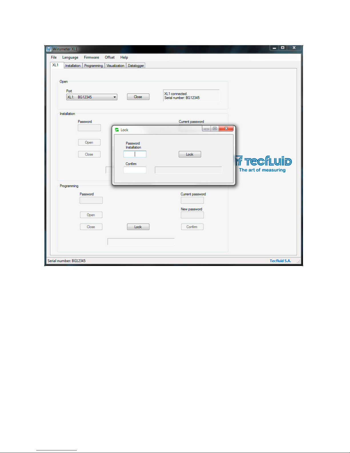
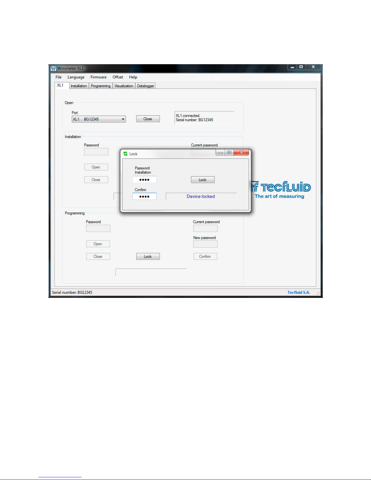
Once done, the following window will appear:
In the “Password” textbox a 4 numeric digit code should be entered, and in the “Confirm”
textbox, the code is confirmed to avoid unintentional errors.
Page 22
22
Once the password is confirmed, press the “Lock” button and the section (“Installation” or
“Programming”) will be locked.
The text “Device locked” will appear, and the program returns to the home screen.
Page 23
23
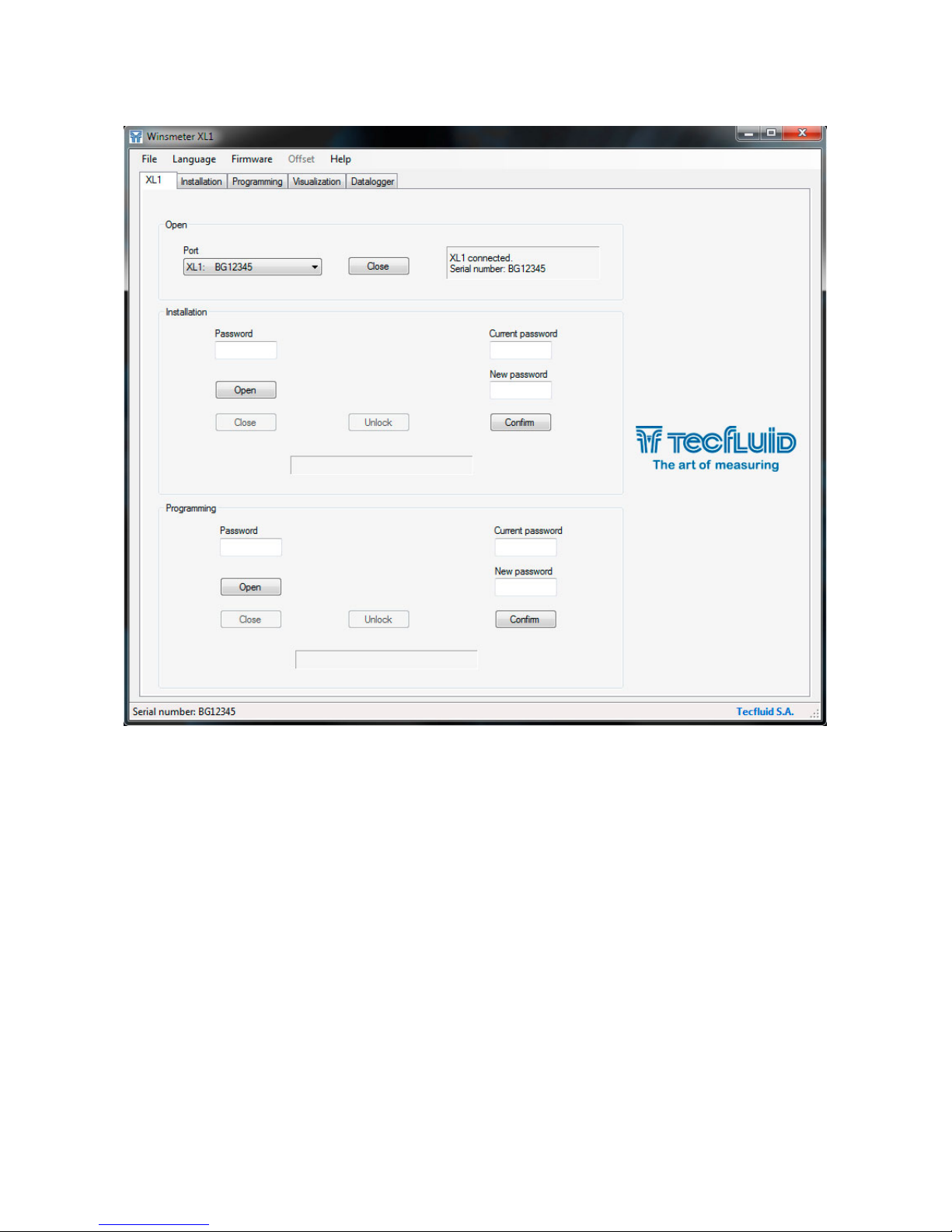
After accessing back to the port and pressing the “Open” button, the screen shows the textbox
to enter or change the locked passwords.
To unlock the section it is necessary to write the correct password and press “Enter” or the
“Open” button. The text “Installation enabled” or “Programming enabled” will appear at the
bottom of the section
Once a section is enabled, pressing the corresponding button “Unlock”, the section will be
unlocked.
Page 24
24
7.4 Access to “Installation”
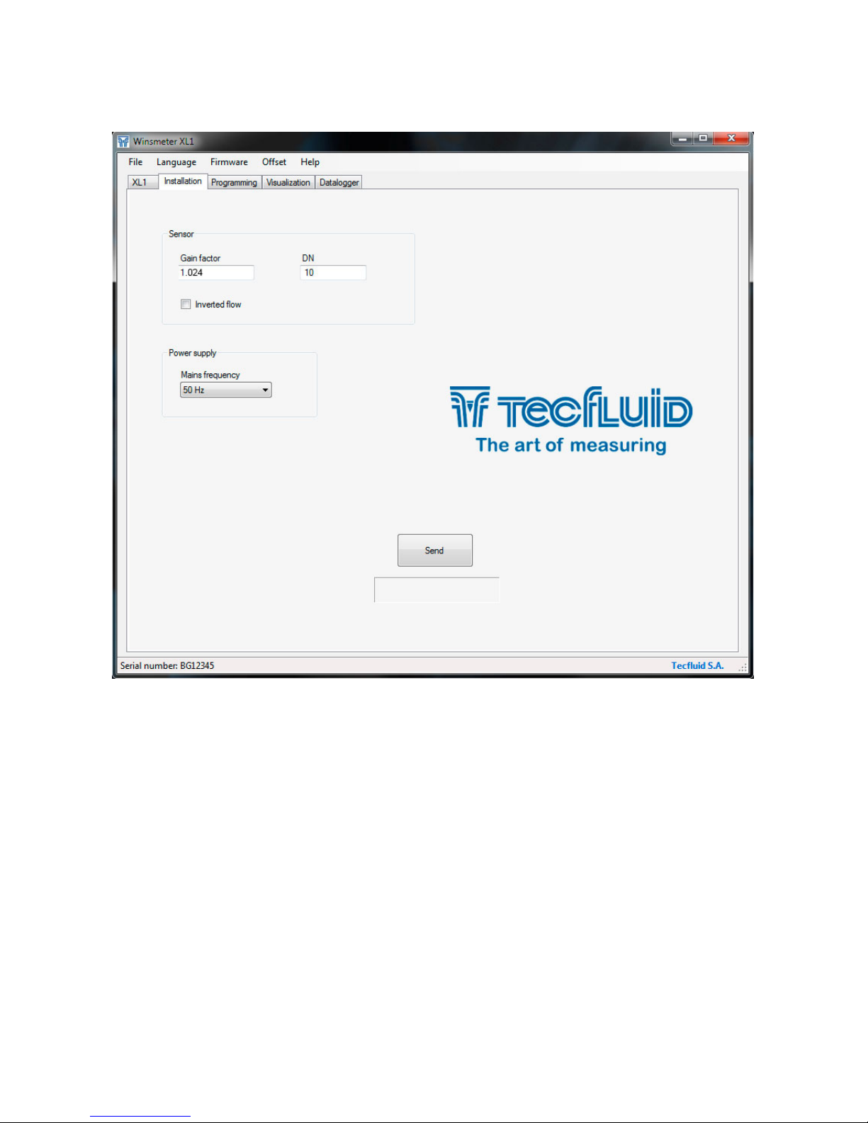
To enter to “Installation” window, press the corresponding tab.
Changing the parameters of this window, the functions of the equipment that affect the
measurement can be programmed. Once the changes have been made, press the "Send"
button to save all data into the device memory.
7.4.1 Sensor
In the Sensor section, the Gain factor, the nominal diameter (DN) and the flow direction can be
configured.
The Gain factor is composed of an integer and three decimals.
It must match the Fg parameter on the device label.
DN is the inner diameter of the sensor. It is also printed on the device label.
The flow rate has a positive sign when going from left to right, looking at the front flowmeter,
and negative in the opposite direction. To change that sign, activate the Inverted flow
checkbox .
7.4.2 Power supply
In this section the mains frequency of the country where the instrument is installed should be
selected.
Page 25
25
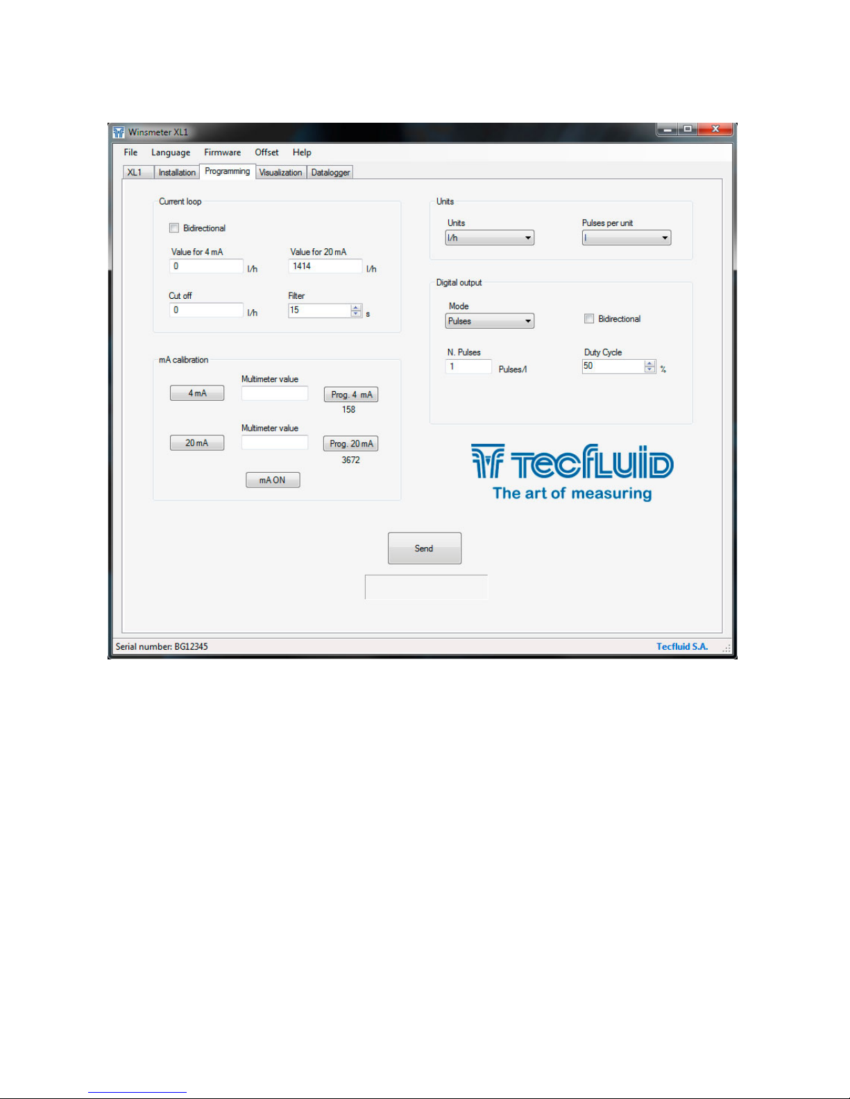
Changing the parameters in this screen, the different functions of the equipment can be
programmed. Once the changes are made, press the “Send” button to save all data into the
device memory.
7.5.1 Current loop
In this section parameters related to the current loop can be configured.
If the Bidirectional checkbox is selected, the analog output will have a value proportional to
flow rate, whether it is positive or negative.
If the checkbox is not selected, the analog output will give a value between 4 mA and 20 mA
proportional to flow rate when it is positive, and it will give a value of 21 mA when the flow
rate is negative.
Values for 4 mA and 20 mA are those that correspond to the current range limits.
Therefore, the current loop will give a linear signal between 4 mA and 20 mA when the input
signal has a value between the programmed values in these textboxes.
By default, the flowmeter is delivered programmed with flow rate values corresponding to
liquid velocities of 0 m/s (4 mA) and 5 m/s (20 mA).
7.5 Access to “Programming”
To enter the Programming window, simply press the corresponding tab.
Page 26

26
The textbox Cut off is useful to program the value below which the XL1 converter will
consider that the flow rate is zero, and therefore the analog output will give 4 mA and the
digital output will be deactivate if it is programmed as Pulses.
By default, the flowmeter is delivered programmed with a cut off value corresponding to a
liquid velocity of 0,5 m/s.
In the box Damping the value in seconds of the filter can be programmed. This filter allows to
obtain stable current readings despite of fluctuations of the flow rate.
The integration time is selected in seconds, with a minimum value of 1 and a maximum value
of 25 seconds.
When there is a sudden variation of the frequency then the filter should react as fast as possible
to give a correct reading of the new value. Therefore, the filter controls for each reading the
deviation of the instantaneous frequency with respect to a reference. If this deviation
exceeds 25%, the filter will stop acting, indicating the instant value, and will start again the
filtering process.
7.5.2 Units
In order to program the device more intuitively, the Flow rate units can be changed so that
the desired working units are selected. Programming parameters that have flow rate units
will update their value when the units are changed.
In the same way, the volume units related to the pulse output can be selected, which are given
in Pulses / Unit of volume.
7.5.3 Digital output
In the textbox Digital output this output can be configured as pulse output or as several
types of alarm.
As in the analog output, if the Bidirectional checkbox is selected, the pulse output will be
operative whether the flow rate is positive or negative.
If it is not selected, the pulse output will be operative only when the flow rate is positive.
In the textbox Number of pulses per volume unit, a number of pulses can be programmed.
This number will give information of each generated pulse, since this will correspond to a
determined volume. If the programmed value involves exceeding the maximum frequency
that the device can supply (5000 Hz), a warning message will appear.
In the textbox Duty cycle, the width of the output pulse can be programmed as a
percentage. The value indicates the percentage of time that the pulse is active with respect
to a complete period. The minimum and maximum values of Duty cycle are 10 and 90%.
Note: Regardless of the Duty cycle value, the pulse width can not exceed 180 ms.
When the digital output does not operate as a pulse output, it can be programmed as an
empty pipe indication, as an inverted flow indication or as a flow alarm.
In this latter case, the values corresponding to the activation and deactivation of the alarm
can be programmed.
7.5.4 Current loop calibration
The XL1 converter is delivered with the current output already calibrated. If you want to
correct a derive of the 4 or 20 mA current values because they do not coincide with the
ammeter used, it can be done in the following way:
To calibrate the 4 mA point, press the button “4 mA”. The transmitter will fix the output to
this value. Then enter the current value indicated in the multimeter and press the button
“Prog. 4 mA”. The transmitter will adjust its output and the multimeter will show 4 mA.
Page 27
27
Follow the same steps for the 20 mA point.
Finally, press the “mA ON” button. The current loop will be calibrated.
Before making a current calibration, be sure that the ammeter used for that is showing the
real measure.
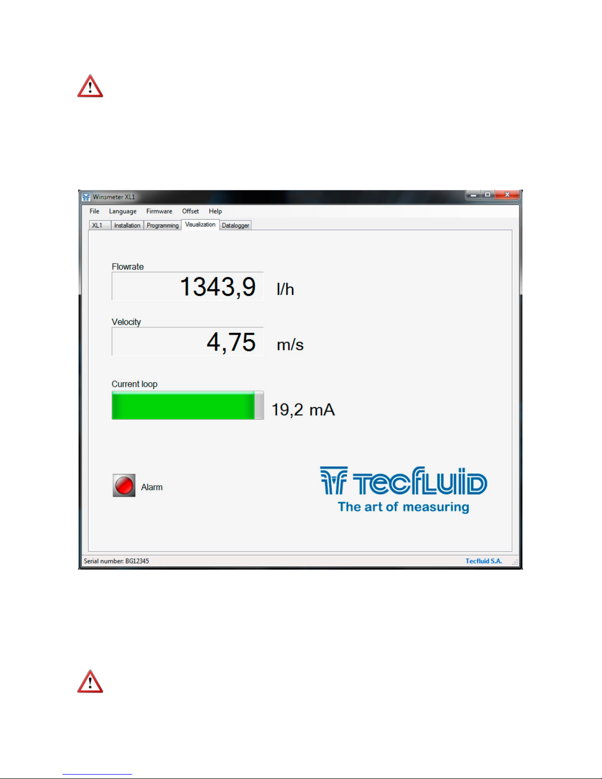
7.6 Visualization
When the communication with the computer port is established (see section 7.2), the tab
"Visualization" opens. This tab lets you view real-time flow rate as well as the liquid velocity.
The current value of the analog output and the status of the digital output if configured as alarm
can also be shown.
It also has messages or warnings regarding the status of the flow meter, such as empty pipe,
coil errors or excessive fluid velocity.
It is an intuitive tool to verify that the instrument has been installed and programmed correctly.
7.7 Zero flow drift adjustment
In the case that there is a zero flow drift (Offset), it is convenient to make an adjustment.
IMPORTANT: The flowmeter is delivered with the zero flow adjusted. Do not make a new
adjustment if it is not a really necessary case. An improper adjustment can impact on
incorrect flow values.
Page 28
28
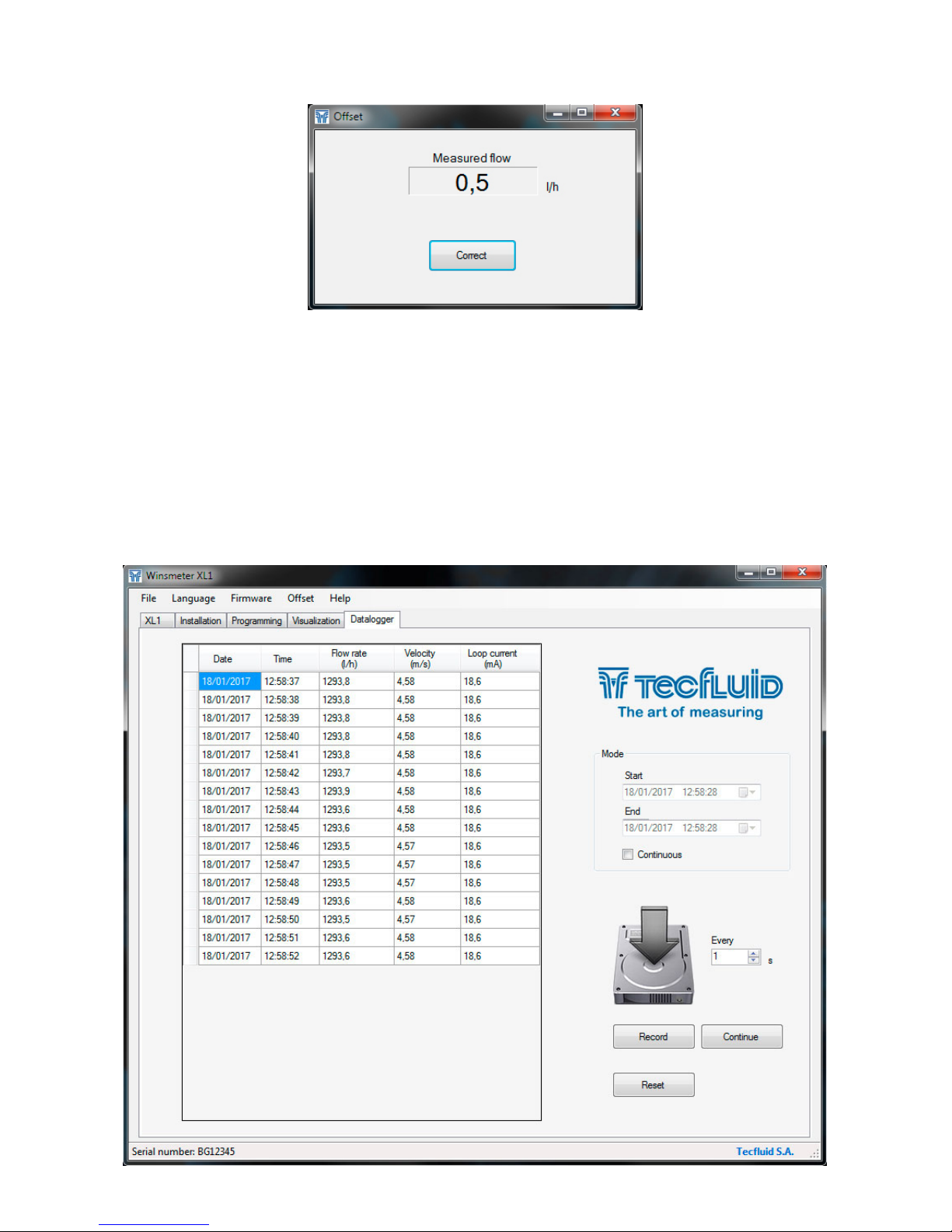
To correct the offset, the flow rate in the installation should be zero, that is, the liquid inside
the pipe where the flowmeter is installed must be completely stopped. In addition, it must be
ensured that the pipe is completely full of liquid so that this adjustment become effective.
Under these conditions, the flow measured by the instrument will appear in the "Measured
flow" box. If this flow has an important zero drift, the text "Very high offset" will appear.
To correct the offset, press the button "Correct".
From this moment, the box "Measured flow" should indicate a value close to zero. The offset
is already corrected. To conclude, close the window.
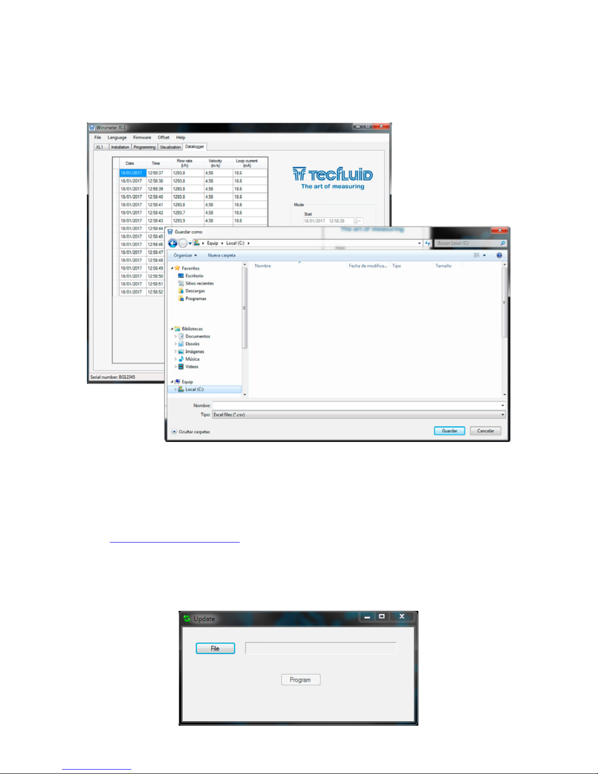
7.8 Datalogger
The adjustment is made by accessing to “Offset” menu. The following window will appear:
Page 29
29
In this window the process of the different variables of the equipment can be registered in a
file.
The time between samples, as well as the start and end time of the record can be selected.
When the "Register" button is pressed, the screen that allows to name the file and select its
location appears.
The created file has CSV format, which can be viewed directly with a spreadsheet.
7.9 Firmware updates
New firmware updates can be published in the website. These updates contain improvements
or bug fixes that make that the equipment operates at best conditions.
The updates can be downloaded from the following link of Tecfluid S.A. website:
www.tecfluid.com\downloads
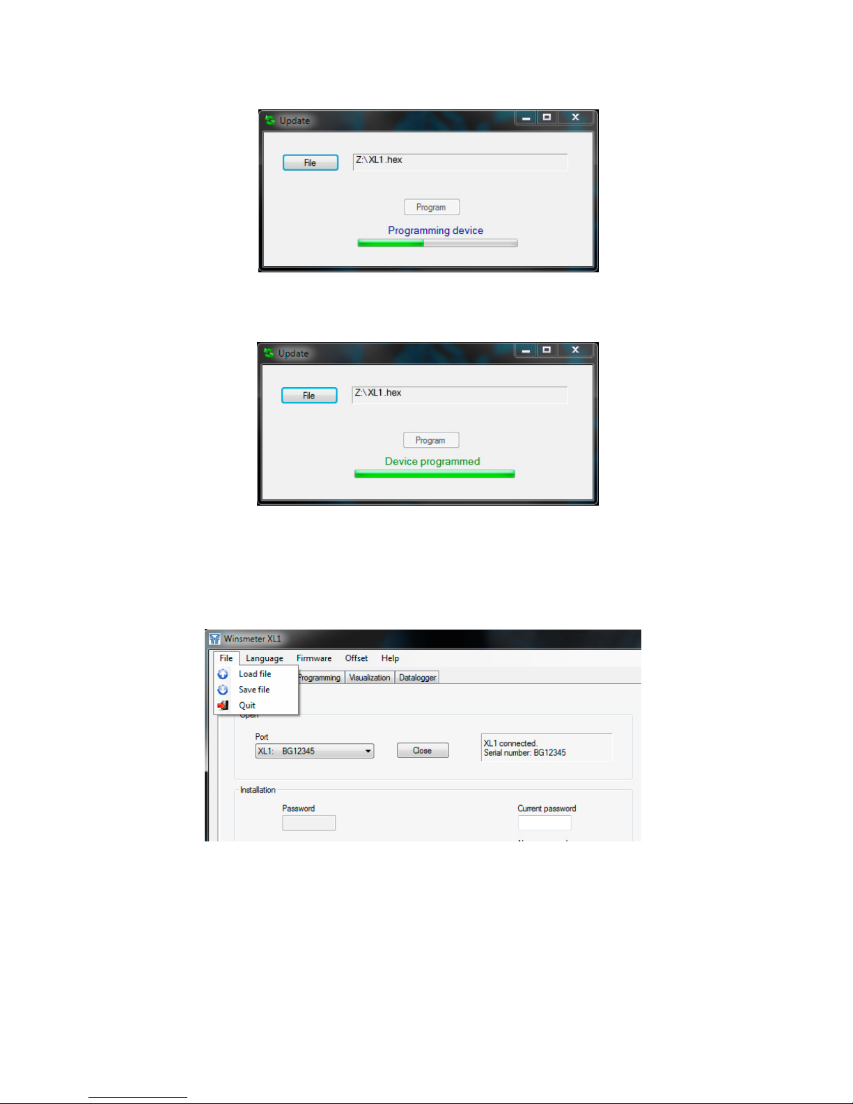
To update the device, go to menu “Firmware” - “Update”, and a screen with the button “File”
will appear. Pressing this button the file explorer can be accessed. The downloaded file has to
be searched there.
Page 30
30
From this moment, the XL1 converter already has the new version of Firmware.
7.10 Configuration file
A device configuration backup can be made by saving data into a file. To do this, go to menu
“File” - “Save file”.
Progress bar will indicate the process, after which the message “Device programmed” will
appear.
The file is saved in the same folder where the Winsmeter XL1 software is located.
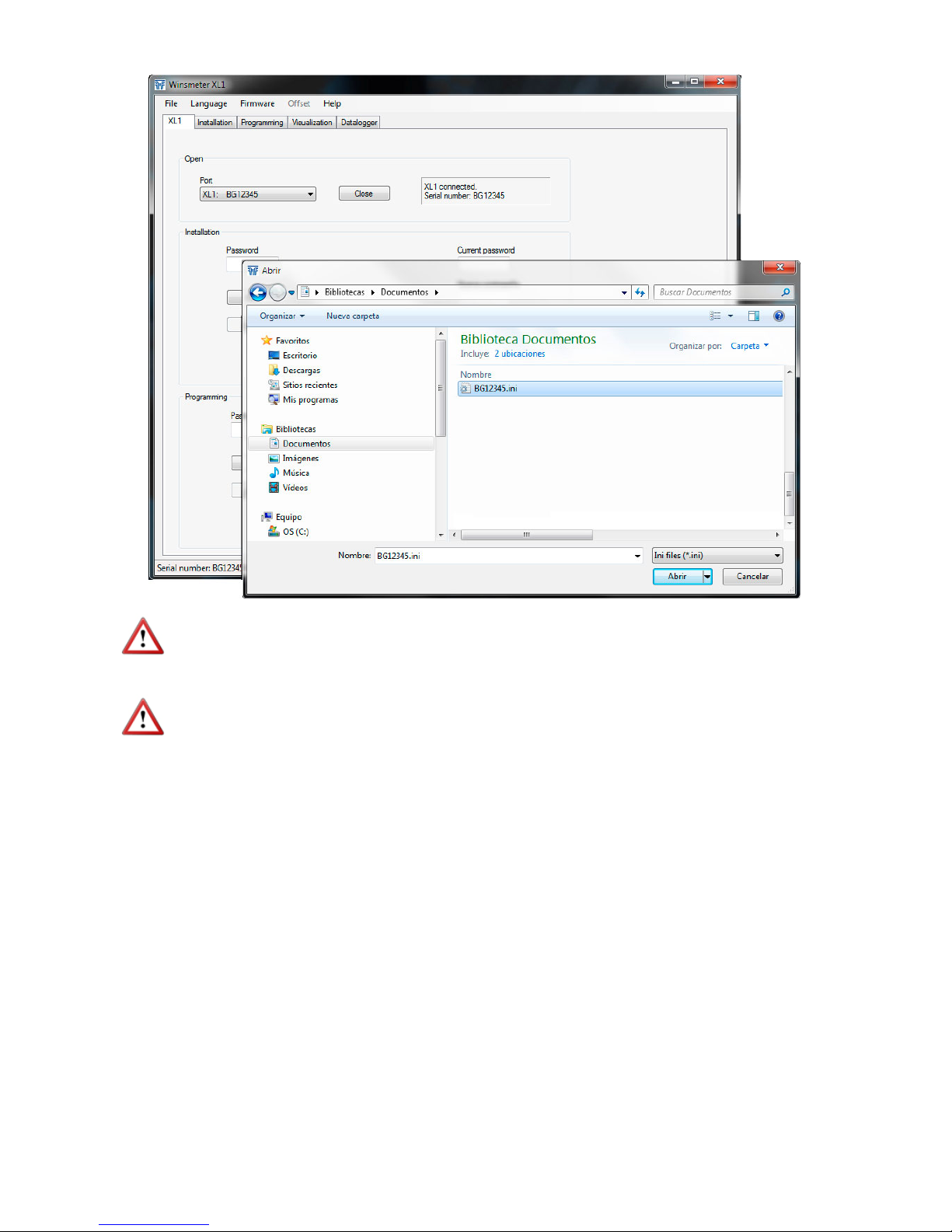
In the same way, a configuration data file can be loaded into the device. To do this, go to the
menu “File” - “Load file”, and the file explorer will appear. The file has to be searched there.
The filename is the serial number and the extension is INI.
Once the file is selected, press the “Program” button. A message “Programming device” will
appear.
Page 31
31
NOTE: When the configuration is saved into a file, the stored data are those in the device
memory. These data may be different from those shown on the Winsmeter program. To ensure
that the data match press the "Send" button in the "Programming" tab.
IMPORTANT: The USB connection is used only for the configuration and commissioning of
the device. In no case it is intended to be used continuously, as a normal mode of operation
in an industrial environment.
8 MAINTENANCE
It is recommended to clean the electrodes in installations where incrustations or appreciable
sedimentations can occur.
Cleaning can be done using liquid detergents and medium hard brushes.
Page 32

32
9 TECHNICAL CHARACTERISTICS
Accuracy
±3.5% reading value for v ≥ 0.5 m/s
±1.75
% reading value for ≤ 0.5 m/s
v (m/s)
Repeatability
± 0.15 % Reading value ± 0.75 mm/s
Velocity range
0.15 ...10 m/s
Temperature
Process temperature: -20ºC … +120ºC
Ambient temperature: -20ºC ... +70ºC
Minimum conductivity
20 μS/cm
Power supply
20 ... 30 VDC 4-wire system Power consumption: ≤ 5 W
Analog output
4-20 mA. Active or passive. Galvanically isolated from the power supply.
Pulse output
Opto-isolated. NPN bipolar transistor. Vmax: 30 VDC. Imax: 30 mA.
Maximum frequency : 5000 Hz
Minimum frequency : 0.01 Hz
General characteristics
Sensor materials:
Neck Body Header Electrodes
EN 1.4301
(AISI 304)
EN 1.4404
(AISI 316L)
PVDF
Hastelloy C
AISI 316L
Titanium
Zirconium
Tantalum
PVDF PVDF
XL1 housing material: Coated aluminium
Ingress protection:
FLOMAT-XL: IP67
Converter XL1: IP66/P67
Page 33

33
10 SAFETY INSTRUCTIONS
The series FLOMAT flowmeters are in conformity with all essential
requirements of all EC directives applicable to them:
2014/68/EU Pressure equipment directive (PED)
2014/30/EU Electromagnetic compatibility directive (EMC)
2012/19/EU Waste electric and electronic equipment (WEEE).
2011/65/EU Restriction of the use of certain hazardous
substances in electrical and electronic equipment
(ROHS).
The declarations UE of conformity can be downloaded from the section “Download” of the
Tecfluid S.A. website. www.tecfluid.com
10.1 Pressure equipment directive
Series FLOMAT of flowmeters, due to their size, are not subject to conformity assessment,
are considered outside the scope of the directive and therefore they have not the CE mark
according to pressure directive. These devices are subject to applicable sound engineering
practice (SEP).
This equipment is considered as being a pressure accessory and NOT a safety accessory as
defined in the 2014/68/EU directive, Article 2, paragraph 4.
10.2 Certificate of conformity TR CU (EAC marking)
Tecfluid S.A. have subjected the series FLOMAT of flowmeters to a
certification procedure according to the technical regulations of the
Customs Union of the Eurasian Economic Union (EEU).
This Certificate is an official document confirming the quality of production with the
standards on the territory of the Customs Union, particularly regarding safety requirements
and electromagnetic compatibility.
Page 34
34
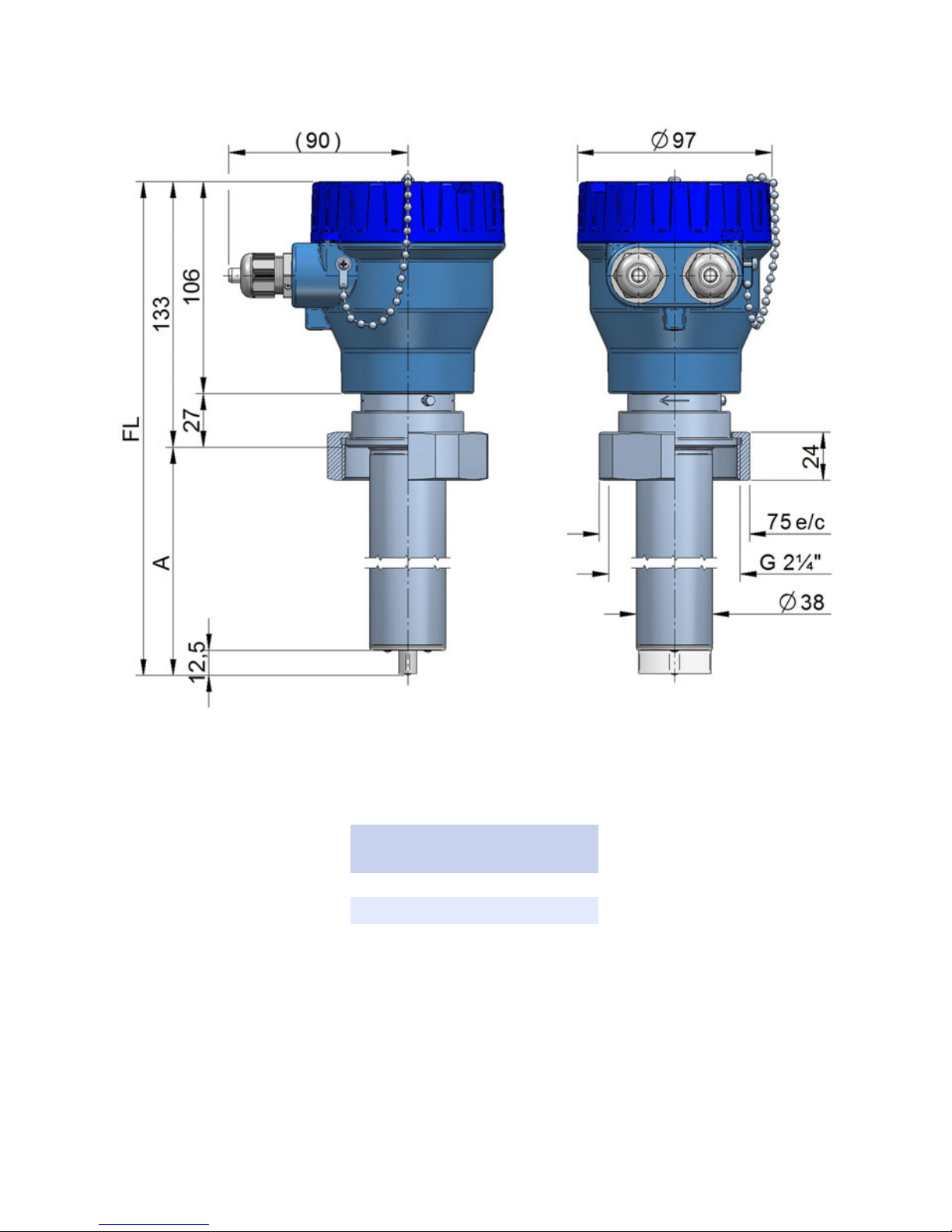
11 DIMENSIONS
FLOMAT-XL (R 2 ¼)
DN A FL
4 … 400 113,5 246,5
500 … 1000 218,5 351,5
11200 … 2000 368,5 501,5
All dimensions in mm
Page 35
35
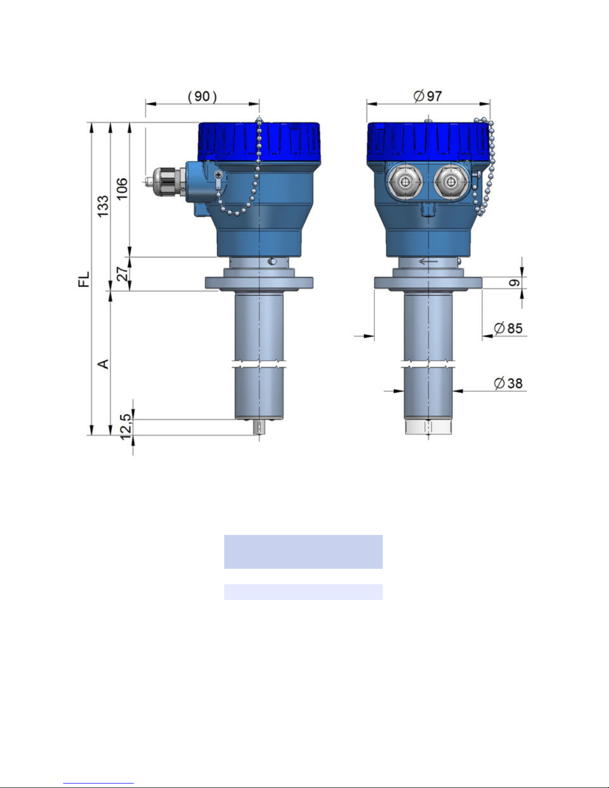
FLOMAT-XL (TF flange)
DN A FL
4 … 400 113,5 246,5
500 … 1000 218,5 351,5
11200 … 2000 368,5 501,5
All dimensions in mm
Page 36
36
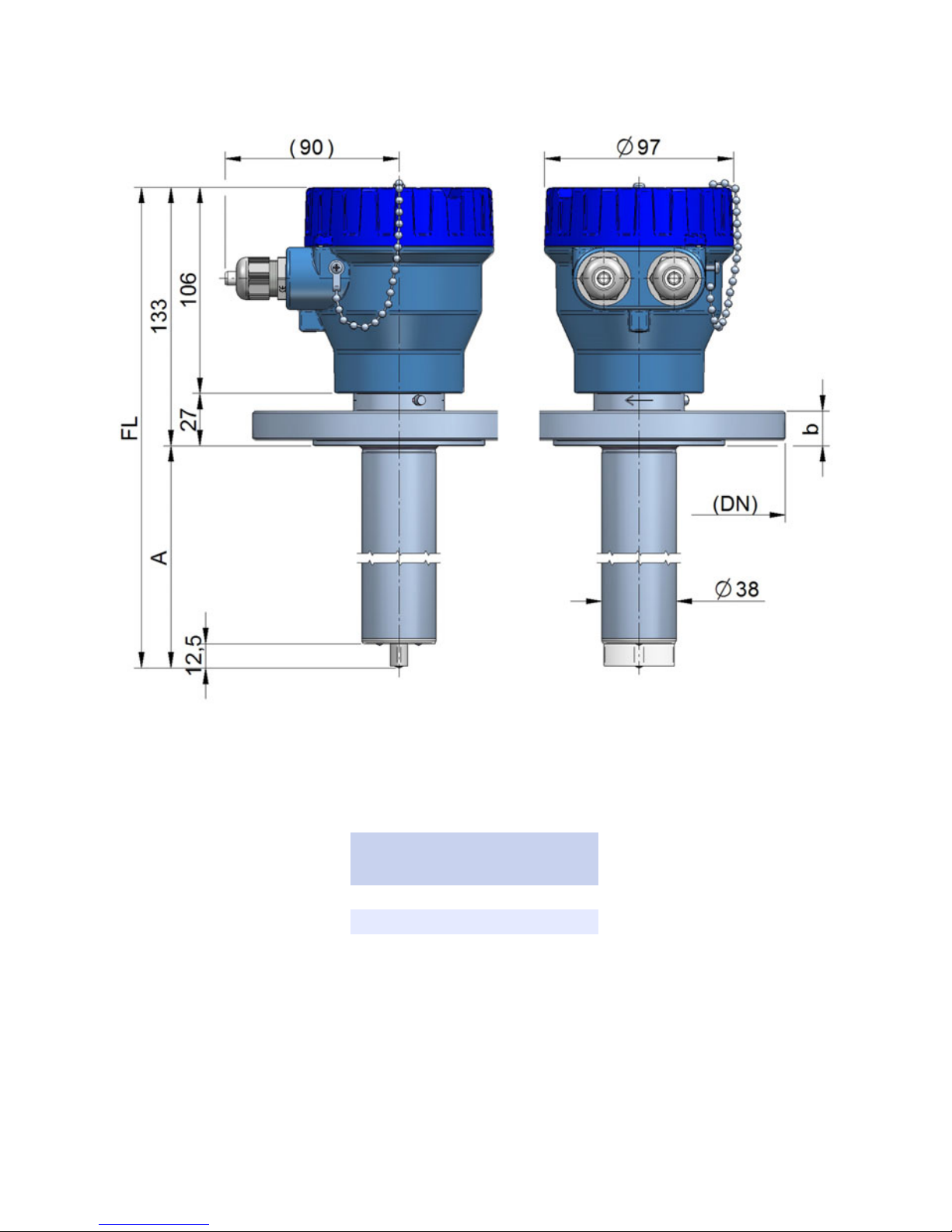
DN A FL
4 … 400 113,5 246,5
500 … 1000 218,5 351,5
11200 … 2000 368,5 501,5
FLOMAT-XL (EN 1092-1 flange)
All dimensions in mm
Page 37
37
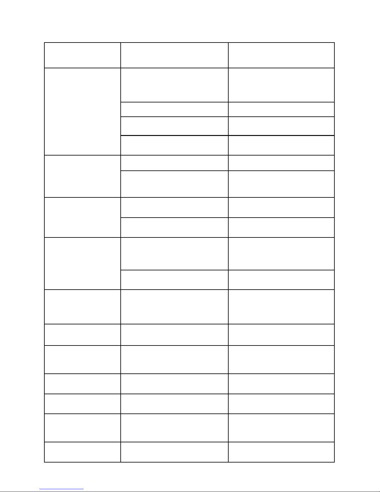
12 TROUBLESHOOTING
roblem Probable cause Solution
Aparece la alarma de
tubería vacía (bucle a 3,6
mA o Winsmeter)
La tubería está vacía
Asegurarse de que la tubería esté
siempre totalmente llena,
instalando el caudalímetro en un
tramo ascendente
No se ha conectado la toma de
tierra
Conectar la toma de tierra del
caudalímetro a un punto metálico
de la instalación que esté en
contacto con el líquido
Aislamiento de los electrodos Limpiar los electrodos del sensor
Cable de electrodos desconectado
Conectar el cable entre el sensor y
el convertidor electrónico
Líquido con muy baja
conductividad
El caudalímetro no es el adecuado
para la aplicación
El caudal es inestable
Suciedad en los electrodos Limpiar los electrodos del sensor.
El producto contiene aire o
partículas no conductoras en
suspensión
Verificar que el medidor de caudal
es el adecuado para esta
aplicación
Indica caudal 0 (bucle a
4 mA o Winsmeter)
Cable de bobinas desconectado
Conectar el cable entre el sensor y
el convertidor electrónico
El caudal es inferior al programado
como CUT OFF
Disminuir el valor del cut off (ver
pág. 26)
Ha entrado producto por los
electrodos debido a corrosión.
Material de electrodos no
adecuado para el líquido
Cambiar sensor
No se ha conectado la toma de
tierra y la opción de tubo vacío está
en OFF
Conectar la toma de tierra del
caudalímetro a un punto metálico
de la instalación que esté en
contacto con el líquido
Sensor inundado por operación en
vacío
Cambiar sensor y revisar
instalación
El caudal indicado es
superior al esperado
Los electrodos están sumergidos
pero la tubería no está
completamente llena
Asegurarse de que la tubería esté
siempre totalmente llena,
instalando el caudalímetro en un
tramo ascendente
No se enciende el LED
Corriente insuficiente de la fuente
de alimentación
Cambiar la fuente de alimentación
La salida analógica
siempre indica 4 mA o
20 mA
Programación inadecuada del
rango de corriente
Programar el rango correctamente
(ver pág. 25)
La salida analógica
siempre indica 0 mA
Cables desconectados Revisar la conexión de los cables
Indica caudal y no hay
caudal
Problem Probable cause Solution
Empty pipe alarm
(current loop at 3.6 mA
or Winsmeter)
Pipe is empty
Make sure that the pipe is
completely full, for example,
installing the flowmeter in a vertical
pipe with upwards flow
Isolation of the electrodes Clean the sensor electrodes.
Electrode cable disconnected
Connect the cable between the
sensor and the electronic converter
Liquid with very low conductivity
The flowmeter is not adequate for
the application
The flow rate is unstable
Dirt on the electrodes Clean the sensor electrodes
The product contains air or nonconductive particles in suspension
Verify that the flowmeter is
adequate for this application
The indicated flow rate
is 0 (current loop at 4
mA or Winsmeter)
Coil cable disconnected
Connect the cable between the
sensor and the electronic converter
The flow rate is smaller than
programmed as CUT OFF
Decrease the value of the cut off
(see page 26)
The instrument indicates
a value when there is not
flow
The sensor is damaged due to
electrodes corrosion
Electrode material not adequate for
the liquid
Change the sensor
Sensor flooded by vacuum
operation
Change the sensor and check the
installation
The displayed flow rate
is higher than expected
The electrodes are immersed but
the pipe is not completely full
Make sure that the pipe is
completely full, for example,
installing the flowmeter in a vertical
pipe with upwards flow
The LED is off
Not enough current from the power
supply
Change the power supply
The analog output gives
always 4 mA or 20 mA
Current output range not properly
programmed
Program the range properly (see
page 25)
The analog output gives
always 0 mA
Cable disconnected Check the cable connection
Page 38
38
ANNEX
Page 39

39
Page 40

40
WARRANTY
Tecfluid S.A. guarantee all the products for a period of 24 months from their sale, against all faulty
materials, manufacturing or performance. This warranty does not cover failures which might be
imputed to misuse, use in an application different to that specified in the order, the result of service or
modification carried out by personnel not authorized by Tecfluid S.A., wrong handling or accident.
This warranty is limited to cover the replacement or repair of the defective parts which have not
damaged due to misuse, being excluded all responsibility due to any other damage or the effects of
wear caused by the normal use of the devices.
Any consignment of devices for repair must observe a procedure which can be consulted in the
website www.tecfluid.com, “After-Sales” section.
All materials sent to our factory must be correctly packaged, clean and completely exempt of any
liquid, grease or toxic substances.
The devices sent for repair must enclose the corresponding form, which can be filled in via website
from the same “After-Sales” section.
Warranty for repaired or replaced components applies 6 months from repair or replacement date.
Anyway, the warranty period will last at least until the initial supply warranty period is over.
TRANSPORTATION
All consignments from the Buyer to the Seller´s installations for their credit, repair or replacement must
always be done at freight cost paid unless previous agreement.
The Seller will not accept any responsibility for possible damages caused on the devices during
transportation.
Tecfluid S.A.
Narcís Monturiol 33
08960 Sant Just Desvern
Barcelona
Tel: +34 93 372 45 11
Fax: +34 93 473 44 49
tecfluid@tecfluid.com
www.tecfluid.com
The technical data described in this manual is subject to modification without notification if the technical innovations in the
manufacturing processes so require.
Quality Management System ISO 9001 certified by
Pressure Equipment Directive certified by
ATEX European Directive certified by
HART is a registered trademark of Fielcomm Group TM
 Loading...