

Page 1
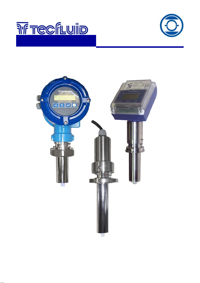
Electromagnetic
insertion sensor
instrumentation
for fluids
Series
FLOMAT FX
Instructions Manual
R-MI-FlomatFX Rev.: 1 English version
Page 2

TABLE OF CONTENTS
1 WORKING PRINCIPLE …………………................................................... 3
2 RECEPTION ............................................................................................ 3
2.1 Unpacking …............................................................................... 3
2.2 Storage temperature .................................................................. 3
2.3 Handling ..................................................................................... 3
3 INSTALLATION ...................................................................................... 3
3.1 Sensor position .......................................................................... 4
3.2 Straight pipe sections ............................................................... 4
3.3 Mixtures ...................................................................................... 5
3.4 Valves ......................................................................................... 5
3.5 Pumps ......................................................................................... 5
3.6 Vibrations ................................................................................... 6
3.7 Magnetic fields ........................................................................... 6
3.8 Temperature ............................................................................... 6
4 MOUNTING THE INSERTION FITTING ................................................. 7
5 MOUNTING THE SENSOR ..................................................................... 9
5.1 Tightening torque ...................................................................... 9
5.2 Electronic converter connection .............................................. 9
6 CONFIGURATION .................................................................................. 9
6.1 Fc factor …………………………..………………….…………........ 9
6.2 Pipe diameter …………………..……………………………........... 9
7 POSSIBLE PROBLEMS WHEN COMMISSIONING ………................... 10
7.1 No flow rate indication ………..…………………………….......... 10
7.2 The reading is not stable ...........................................................
7.2.1 Integration time ........................................................... 10
7.2.2 Filter reset ...................................................................... 10
7.3 Empty pipe ................................................................................. 10
8 MAINTENANCE....................................................................................... 11
9 TECHNICAL CHARACTERISTICS ........................................................ 11
9.1 Materials ..................................................................................... 11
9.2 Insertion fitting connection ...................................................... 11
9.3 General characteristics ............................................................ 11
2
10
Page 3
1 WORKING PRINCIPLE
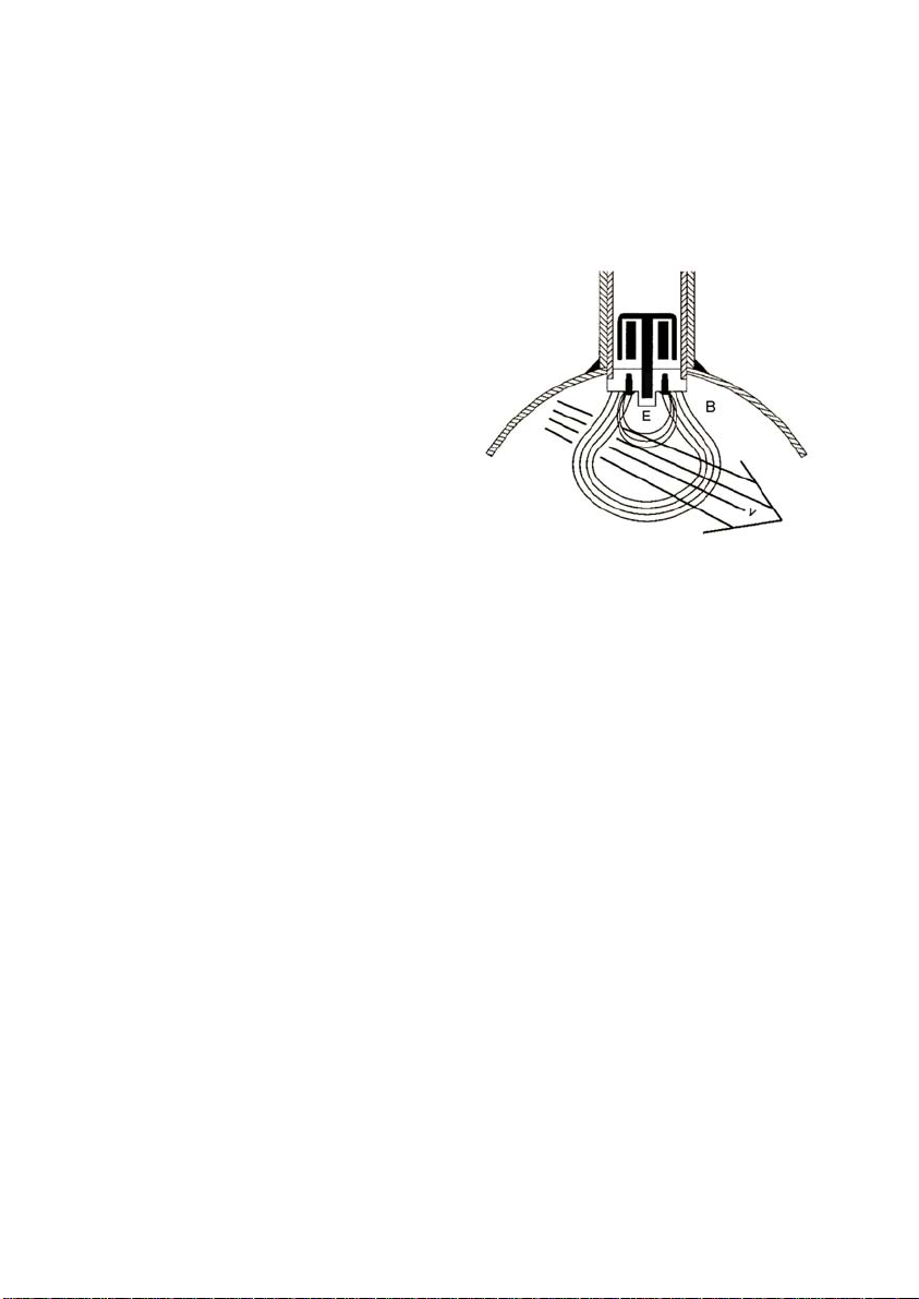
The Flomat electromagnetic insertion flowmeters are based on Faraday’s induction law.
When an electrically conductive liquid flows through a magnetic field, perpendicular to the
flow direction, it induces a voltage E, proportional to the liquid velocity.
Two electrodes in contact with the liquid and positioned perpendicular to the magnetic
field, capture this voltage E.
Where:
E = Measured voltage in the
B = Magnetic flux density
v = Average liquid velocity
d = Distance between electrodes
2 RECEPTION
The Flomat electromagnetic flowmeters are supplied ready for their installation and
operation.
They are also supplied packaged for their protection during storage and haulage.
All the flowmeters have been tested in our calibration rigs to obtain the Fc factor for each
sensor. For more information about the Fc factor, see point 6.1, page 9 of this manual.
2.1 Unpacking
Carefully unpack the instrument, removing any packaging material that could be attached
to the sensor. Do not remove any grease from the collar that fits the sensor to the
electronics housing.
2.2 Storage temperature
-20ºC ...... +60ºC
2.3 Handling
This should always be done with care and without knocks.
3 INSTALLATION
This should be made in a point that guarantees that the pipe is always completely full and
where a turbulent flow profile is completely developed (follow recommendations in point
3.2)
Avoid high points of the pipes where air pockets usually form, or pipes with falling flow
where it can form a vacuum.
Partially full pipes can produce important reading errors.
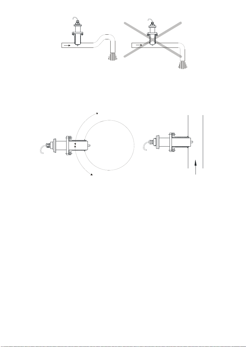
If the point where the Flomat should be installed has a discharge point near to it, it is
necessary to install a siphon in order to avoid any stagnant air in the sensor, as shown in
the following figure.
E = B·v·d
electrodes
3
Page 4
3.1 Sensor position
The most adequate position is in the side of the pipe. In this way, deposits of particles on
the electrodes and air pockets at the top of the pipe are avoided.
60º
60º
3.2 Straight pipe sections
The point where the Flomat will be installed must be a straight pipe section, separated
from elements that can disturb the flow profile, such as elbows, diameter changes, etc.
Depending on the element the minimum necessary distances upstream from the sensor
must be (BS 1042-2.2:1983 standard):
Type of disturbance upstream from the
sensor
90° elbow or T-bend 50 x DN
Several 90° coplanar bends 50 x DN
Several 90° non-coplanar bends 80 x DN
Total angle convergent 18 to 36° 30 x DN
Total angle divergent 14 to 28° 55 x DN
Fully opened Butterfly valve 45 x DN
Fully opened plug valve 30 x DN
Downstream from the sensor, the minimum recommended distance from a disturbing
element is 5 x DN.
4
Minimum distance between
the sensor and the element
Page 5
3.3 Mixtures
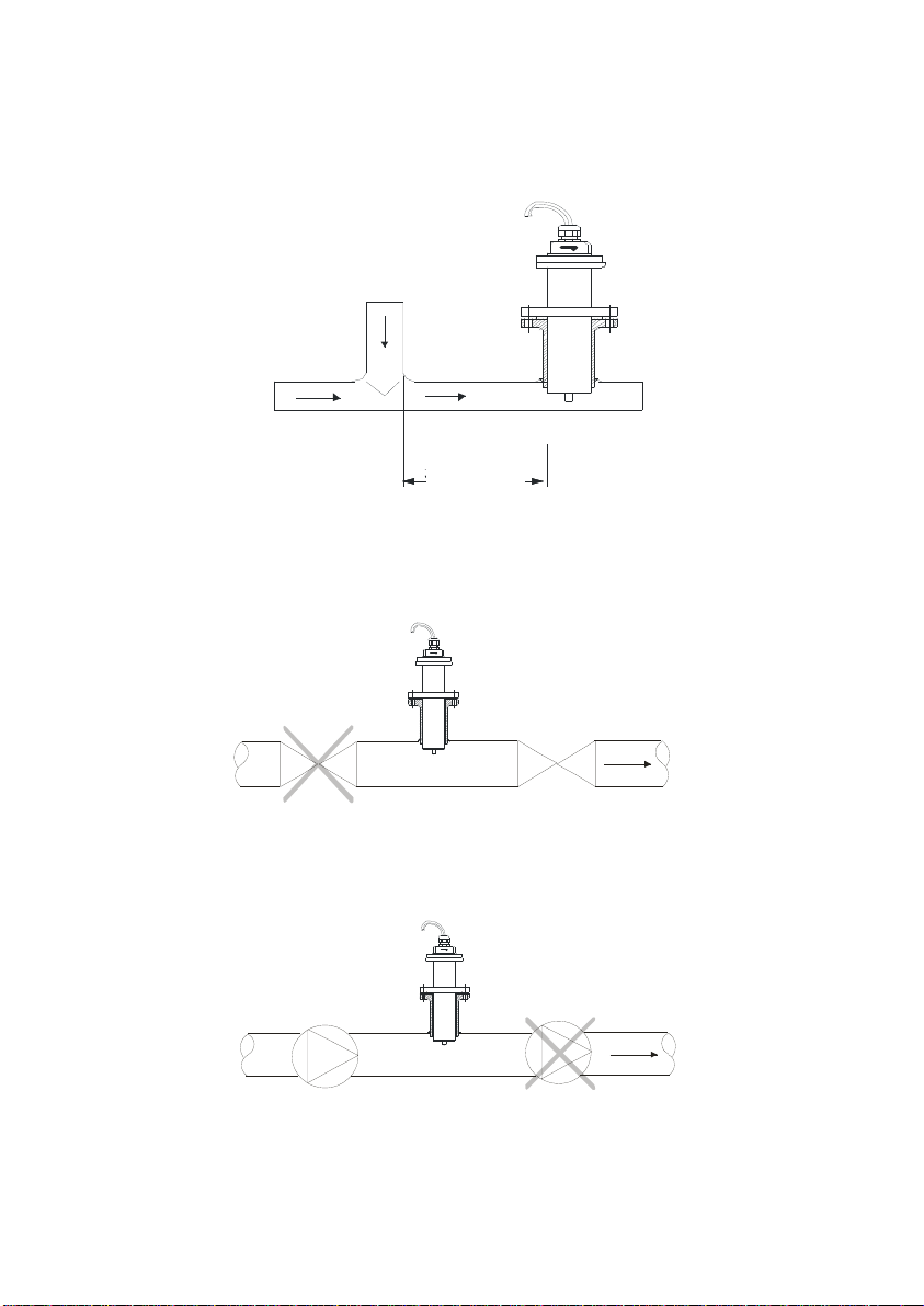
If liquids of different conductivities are mixed it is necessary to install the sensor a
minimum of 50 x DN from the point of mixture in order to obtain a uniform conductivity of
the liquid and stabilize the readings.
If this distance is less, the readings may be unstable.
50 DN
3.4 Valves
Control valves or stop cocks should always be installed downstream from the sensor to
assure that the pipe is always full of liquid.
3.5 Pumps
Pumps should be mounted upstream from the sensor to avoid the suction part of the pump
(vacuum).
5
Page 6
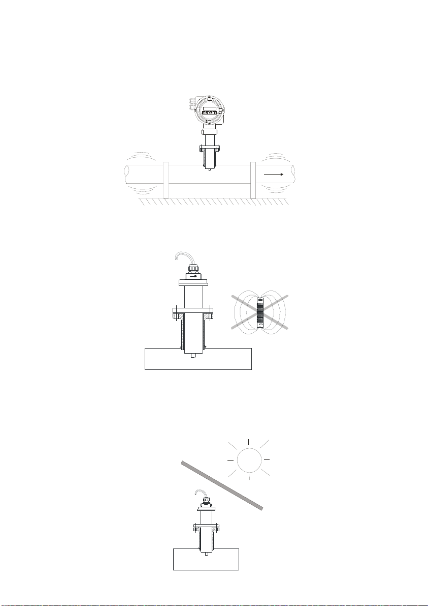
3.6 Vibrations
Vibrations of the pipes should be avoided by anchoring the pipe before and after the
sensor.
The vibration level should be less than 2.2 G in the range of 20 -150 Hz according to IEC
068-2-34.
3.7 Magnetic fields
Strong magnetic fields close to the sensor should be avoided.
3.8 Temperature
In open air installations it is recommended to install a protection to avoid direct sun light on
the flowmeter.
With thermally insulated pipes DO NOT insulate the sensor. High temperatures can
damage it.
6
Page 7
4 MOUNTING THE INSERTION FITTING
The sensor is normally supplied mounted in its insertion fitting. Before welding the fitting to
the pipe , the sensor must be removed to avoid irreparable damage due to excessive
temperatures.
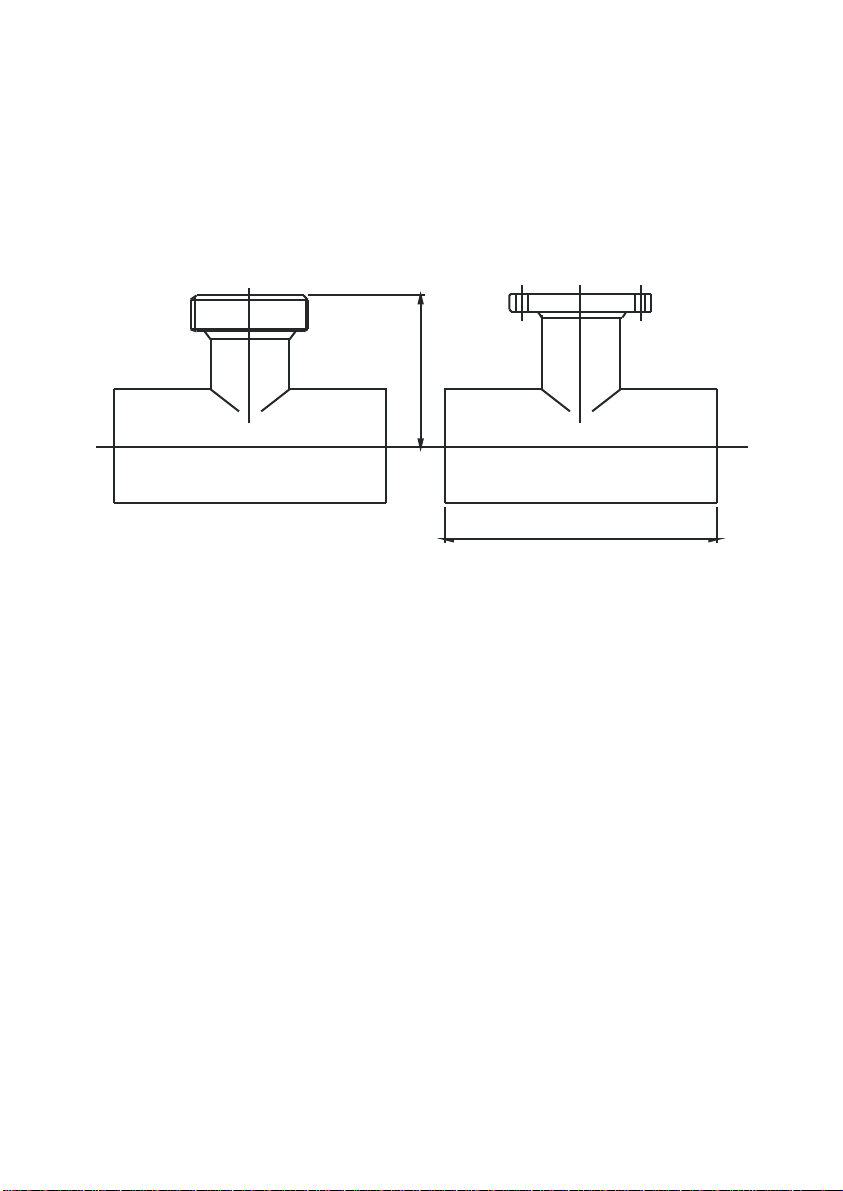
There are two basic types of insertion fitting: threaded fitting and flange fitting.
For the smaller pipe diameters (DN40, 50 & 65) the insertion fitting is supplied fitted to a
short length of pipe with a “T” form. For this type just couple it to the pipe by welding or
gluing in the case of PVC .
DN40 = 110
DN50 = 115
DN65 = 122,5
135......145
For DN80 and greater, there are three lengths for each of the two types of fittings.
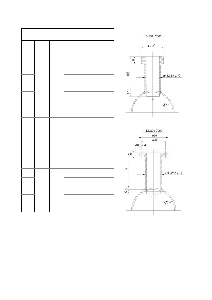
The process of putting the insert in should be done with some precision. The distance (H)
(see drawings on next page) which is what the insert should protrude above the surface of
the pipe is important.
As shown in the table on the next page, to know the distance, the thickness of the pipe (s)
must be known.
To help to position the insert in the pipe, on the side of the insert there is a label with
markings indicating the position of the internal pipe diameter for each DN. Cut this label
above the line corresponding to the DN of the pipe, at a distance equal to the pipe
thickness. Peel off the bottom part of the label. Once the insert is placed into its final
position, where the label was cut must coincide with the exterior of the pipe.
This ensures that the measuring electrodes penetrate far enough in the area of flow profile
that will allow an accurate measurement.
7
Page 8
Sensor
DN
80
100 12,5 85,5-s
length
Fitting
length
C (H)
10 88-s
Qnom
3
/h
m
90,5
141,3
Threaded fitting
125 15,5 82,5-s
150 19 79-s
200 25 73-s
101 93
250 31 67-s
300 37,5 60,5-s
350 44 54-s
400 50 48-s
500
600 75 128-s
700 87,5 115,5-s
206 145
800 100 103-s
900 112,5 90,5-s
1000 125 78-s
1200
1400 175 178-s
1600 200 153-s
1800 225 128-s
2000 250 103-s
356 190
62,5 140,5-s
150 203-s
220,9
318,1
565,5
883,6
1.272.,3
1.731,8
2.261,9
3.534,3
5.089,4
6.927,2
9.047,8
11.451,1
14.137,1
20.357,5
27.708,8
36.191,1
45.804,4
56.548,7
Flange fitting
Example:
Suppose a pipe of 300 mm inner diameter (DN300) and 5.5 mm thick. In the table we can
see that the distance that the insertion fitting must extend above the exterior wall is H =
60,5 - s = 60,5 -5,5 = 55 mm.
The values in the table are calculated with the gasket supplied with the instrument, which
is 3 mm thick. If the thickness of the gasket is changed, the value of H will change.
The equation to calculate H’ for a gasket of thickness d is the following:
H’ = H + 3 - d
In the previous example, if the gasket was 5 mm thick, the distance that the fitting should
extend above the exterior wall would be H’ = 55 + 3 - 5 = 53 mm.
8
Page 9

Drill a 48.5 mm diameter hole in the pipe to insert the fitting and weld the fitting to the
pipe.
The axis of the insertion fitting should be perfectly perpendicular to the pipe axis.
If the pipe is made of concrete or other material to which the insertion fitting cannot be
welded, a collar fitting or saddle fitting should be used. In this case, please contact us to
inform about the suitable sensor length.
5 MOUNTING THE SENSOR
Once the insertion fitting is mounted, place the flat seal in its position and install the
sensor with the arrow pointing in the flow direction. The electrodes must be perfectly
perpendicular to the pipe axis.
In order to align the sensor, the two bolts or pins situated in each side of the cylinder in
the top of the Flomat sensor must be aligned with the axis of the pipe and the arrow
pointing in the flow direction.
5.1 Tightening torque
The tightening torque for the flange screws should not exceed 7.1 Nm.
The tightening torque for the threaded fitting should not exceed 21 Nm.
5.2 Electronic converter connection
The top of the sensor is cylindrical and it can be adapted to a connector with cable for
remote electronics or to other types of electronic housings directly on the head.
In the event that during the installation of the sensor the electronics or the sensor cable
were disconnected, simply replace the two connectors on the sensor, push the mesh
above the head, tight the side screws, and in the case of separate electronics, tigth the
cable gland in order to keep the seal.
In the cases where the electronic converter is separate, refer to the converter instructions
manual for the cable connection.
6 CONFIGURATION
For the commissioning, in most of cases it is necessary to configure the equipment to put
the installation into service.
6.1 Fc factor
The Flomat sensor has been calibrated in our calibration rigs to determine the “Fc” factor.
This factor corresponds to the signal level with a certain liquid velocity in the pipe.
If the sensor is supplied with an electronic converter, this factor will already be
programmed into the converter, but if not, the electronic converter must be programmed
by entering this factor (Fc).
6.2 Pipe diameter
It is very important to verify that the converter is configured for the diameter of installation
pipe.
For XT5 converter series, the inner diameter (DN) is programmed directly in mm. For the
MX converter series of converters, the inner diameter is programmed by means of the
nominal flow rate equivalent to a velocity of 5 m / s (Qnom.). Qnom values depend only on
the inner diameter of the pipe and they are shown in the table on page 8 for most
standard sizes.
9
Page 10

7 POSSIBLE PROBLEMS WHEN COMMISSIONING
7.1 No flow rate indication
Check that the cables for remote electronic units have been correctly connected. Inverted
coil cables or electrode cables will have the same effect as inverting flow direction.
Check that the electrodes are perpendicular to the flow direction. If the sensor is mounted
with the electrodes aligned with the flow direction the output signal will be very poor and
the flow rate reading could be zero.
Check that the electrodes are clean and free from grease. If the electrodes are dirty with
grease or other insulating substance there will be no output signal. In this case the
electronics units usually indicate “empty pipe”. See the point 8, to proceed to clean them.
Check that the pipe is completely full. (That the electrodes are fully covered with liquid).
7.2 The reading is not stable
Check that there are no obstacles or bends near the sensor, especially upstream from it,
that can produce important turbulences (see table of page 4).
Check that there are no air bubbles or solids that interrupt the conduction path between
the electrodes producing instability in the signal level
The electronic converters have a configurable filter. In most cases a stable reading can be
obtained by means of the filter configuration. The filters have two characteristics that
govern their operation:
7.2.1 Integration time
It is the time during which the average value is calculated. In the supposition that the
instrument takes 10 readings per second, if an integration time of 5 seconds is selected
the flow rate reading will be the average of the last 50 readings. If an integration time of
10 seconds is selected the flow rate reading will be the average of the last 100 readings.
Logically, when there are fluctuations in the flow rate, the greater the integration time is,
the more stable the readings will be.
7.2.2 Filter reset
Whilst the oscillations are within the window defined by the selected % in the filter reset
configuration, the filter will average the readings over the established integration time.
When there are readings outside this window the averaging of the readings will start again
and the flow rate reading can give the instantaneous reading. In these cases the filter
reset window must be increased to obtain a more stable reading.
The only inconvenience in leaving the window at very high levels is that the response to a
sharp change in flow rate will be slower.
7.3 Empty pipe
Even when it has been checked that the pipe is full, if there is empty pipe indication, this
may be caused by electrical currents that flow in the liquid inside the pipe. This problem is
more common when the pipe is made of plastic or other insulating material. To eliminate
this problem the metallic housings should be disconnected from the mains earth. The
electronic converters have the possibility to disconnect the empty pipe detection.
10
Page 11
8 MAINTENANCE
It is recommended to clean the electrodes in installations where appreciable incrustations
or sedimentations can occur. Dirty electrodes can cause unstable readings and in extreme
cases indication of empty pipe detection
Cleaning can be done using liquid detergents and medium hard brushes.
The Flomat-Tap System allows maintenance of Flomat sensors without having to stop
flow of the liquid in the pipe. If you have one of these, refer to its instruction manual for
operation.
9 TECHNICAL CHARACTERISTICS
9.1 Materials
Sensor housing: EN 1.4404 (AISI 316L), PVDF
Electrodes head: PVDF
Gasket: NBR
9.2 Insert fitting connection
G2 1/4 thread, DIN flange, special flange.
9.3 General characteristics
Accuracy: ± 3,5%
(with respect to measured value, for velocities faster than 0.5 m/s)
Minimum electric conductivity: 20 µS/cm
Minimum recommended liquid velocity: 0.5 m/s
Process temperature (liquid): Compact -20 ... +70 ºC
Remote -20 ... +130 ºC
Ambient temperature: -10 ... +50 ºC
Standard pressure: PN16
Ingress protection: IP68 10 m H
O
2
Conforms with the Directive 2002/96/CE
Conforms with the Directive 2004/108/CE
Conforms with the Directive 97/23/CE
This equipment is considered as being a pressure accessory and NOT a safety
accessory as defined in the 97/23/EC directive, Article 1, paragraph 2.1.3.
11
Page 12

WARRANTY
Tecfluid S.A. GUARANTEES ALL ITS PRODUCTS FOR A PERIOD OF 24 MONTHS, after
consignment, against all defects in materials and workmanship.
This warranty does not cover failures which can be impu te d to misuse, use in an appli catio n dif fe ren t
to that specified in the or der, the result of service or modification b y un-authorized persons, bad
handling or accident.
This warranty is limited to cover the repair or replacement defective parts which have not been
damaged by misuse.
This warranty is limited to the repair of the equipment and all further and eventually following
damages are not covered by this warranty.
Any consignment of equipment to our factory or distributor must be previously authorised. The
consignment should be done with the equipment well packed, clean of any liquids, grease or
hazardous materials. Tecfluid S.A. will not accept any responsibility for damage done during
transport.
Together with the equipment, a note should be enclosed indicating the failure obs erved, the name,
address and telephone number of the sender.
SHIPPING
In the event of damages during shipping, claim directly to the carrier over a period of less than 24
hours. Tecfluid is not responsible for any damage caused during the shipment of material.
TECFLUID, S.A.
Narcís Monturiol, 33
E-08960 Sant Just Desvern
Tel. + 34 93 3724511 - Fax + 34 93 4734449
E-mail: [email protected]
Internet: www.tecfluid.com
The technical data in this pamphlet is subject to modification without notif ication, if the technical innovations in the product or
manufacturing processes so require.
 Loading...