

Tecella Triton+ User Manual
3001 Red Hill Ave, Suite 1-204
Costa Mesa, CA 92626
Phone +1-714-641-1709
Fax +1-714-641-1569
Triton+ User’s Manual

T able of Contents
Before You Begin.....................................................................................................3
1.1 Introduction................................................................................................3
1.2 Package Contents.....................................................................................3
1.4 Computer Requirements..........................................................................3
1.5 Installation Overview.................................................................................3
Installation................................................................................................................4
2.1 Select the Driver Setup File for Your OS.................................................4
2.2 Install Driver File Onto Your Computer....................................................5
2.3 Connect the Power Supply To the Amplifier............................................7
2.4 Plug In the Power Supply Into an AC Outlet ...........................................8
2.5 Connect the USB Cable To the Amplifier and the Computer.................9
2.6 Turn On the Amplifier................................................................................9
2.7 Associating the Driver and the Amplifier (Windows XP).......................10
Getting Started With TecellaLab...........................................................................13
3.1 Install TecellaLab....................................................................................13
3.2 Launch TecellaLab..................................................................................15
3.3 Start Acquisition ......................................................................................16
3.4 Changing Gain (Rf setting).....................................................................17
3.5 Changing Source....................................................................................18
3.8 Save Data To a File................................................................................19
3.9 Convert Data to Tab Delimited or ATF Format.....................................22
3.10 Using TecellaLab..................................................................................22
Getting Started With WinWCP..............................................................................24
4.1 Download WinWCP Setup File..............................................................24
4.2 Download WinWCP User Guide............................................................24
4.3 Install WinWCP.......................................................................................24
4.4 Start WinWCP.........................................................................................24
4.5 Set Laboratory Interface Card to “Tecella Triton”..................................25
4.3 Using WinWCP.......................................................................................26
Connecting To Your Setup....................................................................................27

2
Using TecellaLab...................................................................................................28
Hardware Calibration.............................................................................................29
6.1 Check For Hardware Drift.......................................................................29
6.2 Option 1: Re-start the Application.........................................................29
6.3 Option 2: Re-run Hardware Calibration................................................30
Specifications.........................................................................................................32
7.1 Source Selector.......................................................................................32
7.2 Headstage and Feedback Gain Resistor (Rf).......................................32
7.3 Current Range & Current Resolution.....................................................33
7.4 A/D Resolution & Sampling Rate...........................................................33
7.5 Analog Filter ............................................................................................33
7.6 Noise........................................................................................................34
7.7 Capacitance Compensation...................................................................35
7.8 Series Resistance Compensation..........................................................36
7.9 Analog Leak Compensation (optional) ..................................................36
7.10 Command Voltage................................................................................36
7.11 Holding Voltage.....................................................................................36
7.12 Junction Offset Compensation.............................................................37
7.13 Zap.........................................................................................................37
7.14 Sync Out................................................................................................37
7.15 Trigger In...............................................................................................37
7.16 Acquisition Modes.................................................................................37
7.17 Acquisition Data Format.......................................................................37
7.18 Power Supply........................................................................................37
7.19 Power Requirements............................................................................37
7.20 Mechanical Dimensions .......................................................................37
Troubleshooting & Support....................................................................................38
Technical Support.............................................................................................38

3
Chapter
1
Before You Begin
1.1 Introduction
The Triton+ is a full-featured whole cell patch clamp amplifier, available in 1, 2, 4, or 8 channel
configurations. The digitizer, the head stages, and the model cells are all integrated inside the
Triton+ amplifier simplifying setup of the work environment. Triton+ communicates to the
computer via a standard USB 2.0 cable, so no special hardware is required on the computer.
1.2 Package Contents
Please confirm that the following items were included in the Triton+ package.
Triton+ amplifier
Power supply
USB cable (Mini-USB)
What You May Need To Provide
Since AC outlets vary depending on your country, you may need to provide your own
AC chord to connect between the power supply and the AC outlet.
1.4 Computer Requirements
The following is the minimum computer requirements for using the Triton+.
2GHz single core processor or 1.4GHz dual core processor
1GB RAM
10GB free space on your Hard Drive
One available USB 2.0 port
Windows XP, Vista, or 7
1.5 Installation Overview
The Triton+ setup can be summarized in the following 5 steps.
1. Install Driver file
2. Install Software
3. Plug in power supply
4. Plug in USB cable
5. Turn on the amplifier to associate Driver with the amplifier
These steps will be explained in greater detail in the following two chapters.

4
Chapter
2
Installation
2.1 Select the Driver Setup File for Your OS
Before plugging in the amplifier to the computer for the first time, please follow the following
steps to install the FrontPanel driver file onto your computer. The FrontPanel driver file comes
in 32-bit version and 64-bit version. Please install the correct version that matches your
operating system (OS). You can check which version OS you are running by opening Control
Panels and selecting System. If you do not see any mention of 64-bit Operating System, then
please choose the 32-bit driver file.
Previous Driver Installations
If you have previously installed the FrontPanel driver onto your computer, there is no
need to reinstall the driver file, and you can skip this section and the next section on
FrontPanel driver file installation.
Driver Setup File for 32-bit Windows XP, Vista, 7
For 32-bit Windows XP, Vista, or 7 OS, please use the file called
“FrontPanel-DriverOnly-Win-Win32-3.1.0.exe”. Double click on the
icon to begin installing the driver files.
Driver Setup File for 64-bit Windows XP, Vista, 7
For 64-bit Windows XP, Vista, or 7 OS, please use the file called
“FrontPanel-DriverOnly-Win-x64-3.1.0.exe”. Double cli ck on the i con
to begin installing the driver files.
5
2.2 Install Driver File Onto Your Computer
Follow the steps below to install the FrontPanel driver file onto your computer.
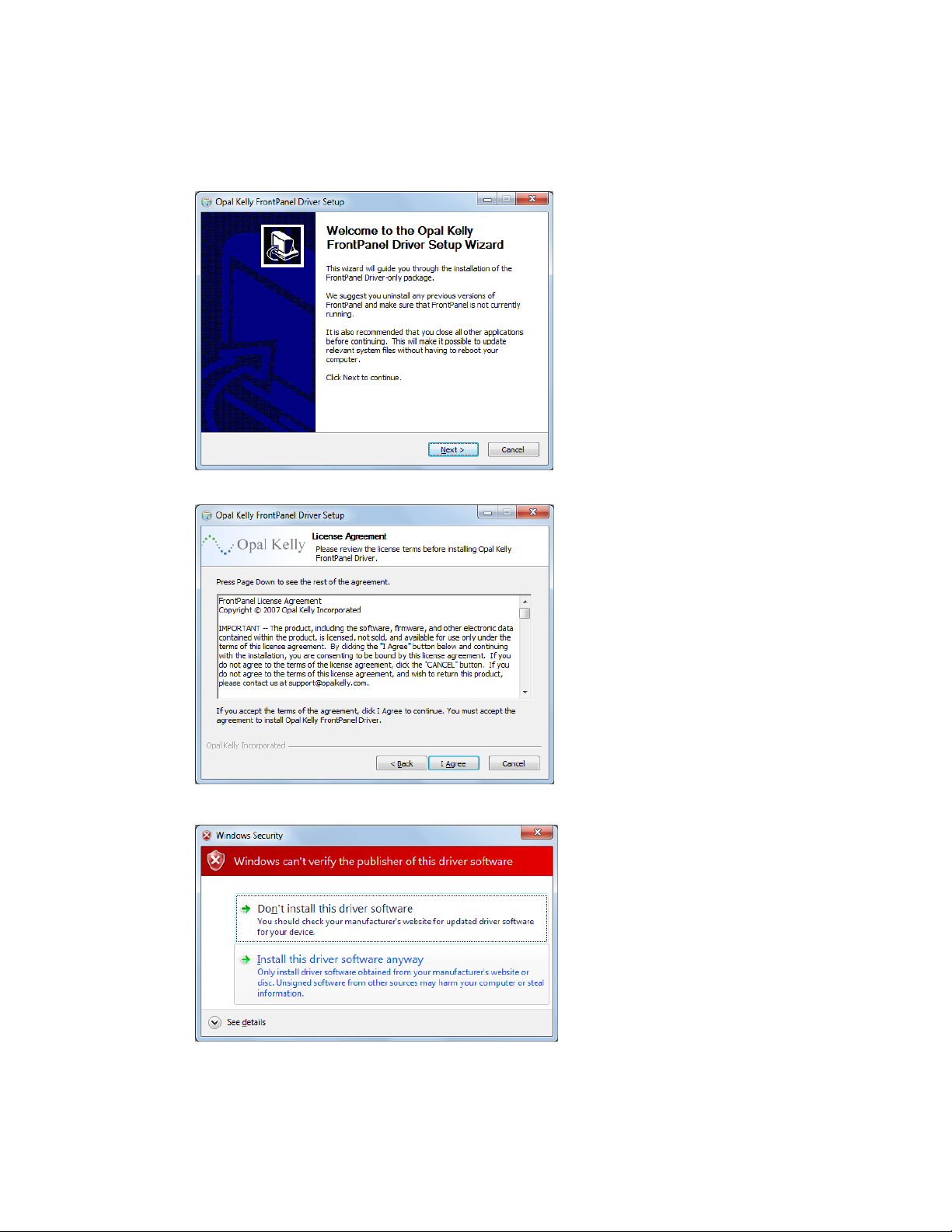
First, you will see the Setup Wizard
welcome screen. Click on “Next” to
proceed.
Next, you will see Opal Kelly’s
License Agreement. Click on “I
Agree” to install the driver.
Depending on the security setting of
your computer, you may see this
warning screen. Click on “Install thi s
driver software anyway” to continue
with installation.

6
This screen may momentarily
appear during driver installation.
After the FrontPanel driver files has
been successfully installed on your
computer, you will see this
confirmation screen. Click on
“Finish” to exit the installation.
Although the driver files have been
installed on your computer, they
have not been associated with the
amplifier yet. The driver file and the
amplifier will be associated the first
time the amplifier is connected to the
computer and turned on.
This warning screen may appear on
computers running Windows Vista
and Windows 7, even if the
installation was successful. Click on
“Cancel” to exit the warning screen.

7
2.3 Connect the Pow er Supply T o the Amplifier
Power
Connector
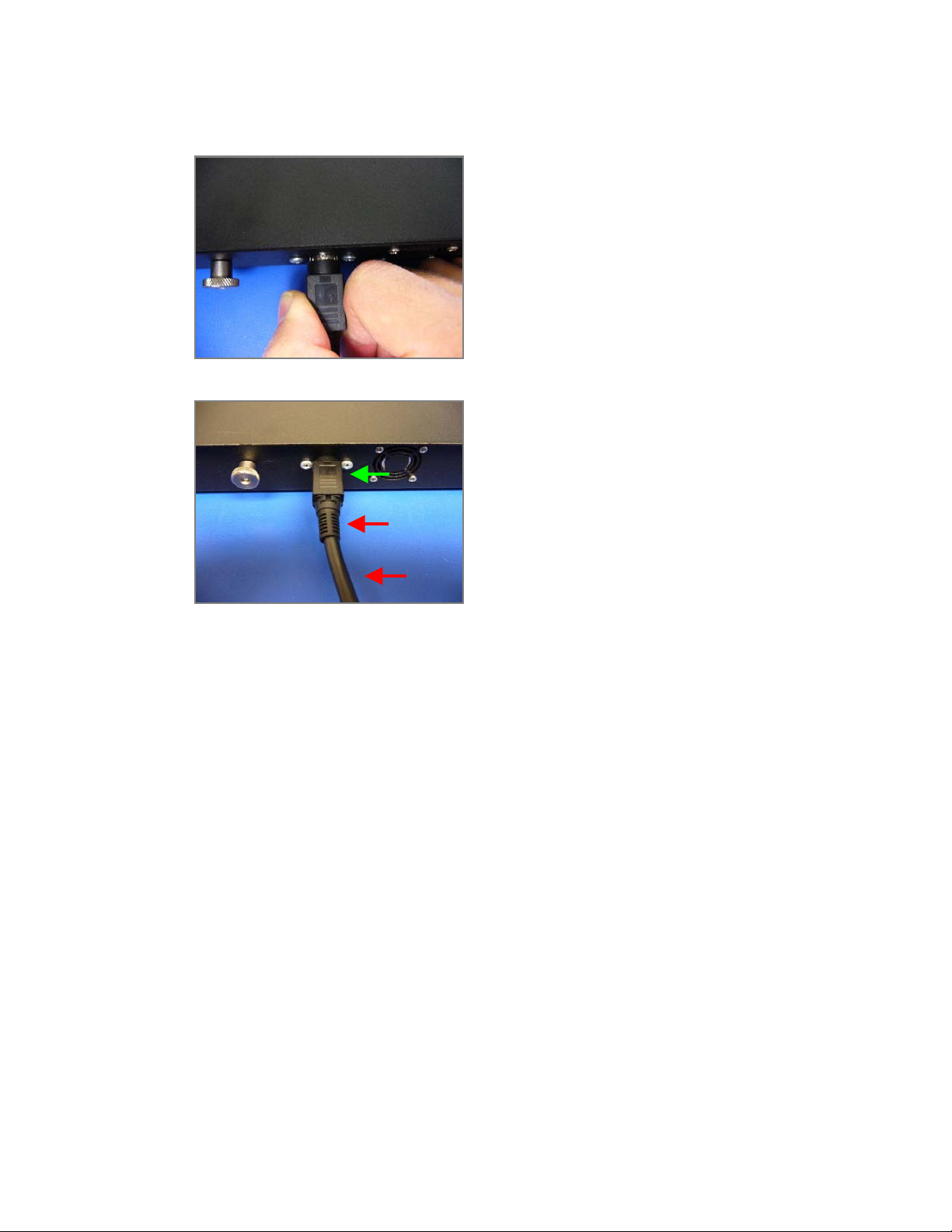
Locate the power jack on the back of the amplifier as indicated by the arrow below.
Locate the connector of the power supply.
Power
Jack
Test for Proper Insertion
Insert the power connector firmly into the power
jack. The power connector has a locking
mechanism, so it is important that the power
connector is fully inserted into the power jack.
Considerable force is required to properly insert the power connector and engage the
locking mechanism. To test for proper insertion, pull snugly on the cable. If the
connector gets loose, the insertion force was insufficient to lock the connector. Please
try again by applying more insertion force.
8
Caution! Extremely Important When Detaching Power Cable
When detaching the power cable from the
amplifier, in order to disengage the locking
mechanism, you must first pull back on the
connector cover as shown.
As you pull back on the connector cover, the silver
colored shield should become visible. Continue
pulling on the connector to detach the power cable.
NEVER attempt to detach the power connector by
pulling on the cable or on the stress relief of the
cable.
YES
NO !
NO !
2.4 Plug In the Powe r Supply Into an AC Outlet
Plug in the power supply into an AC outlet using the appropriate AC chord for your country’s
outlet.

9
2.5 Connect the USB Cable T o the Amplifier and the Computer
A standard Mini-USB cable (as shown) is included
with the amplifier.
Plug the small end of the USB cable into the USB port of the amplifier indicated below.
Plug the large end of the USB cable into the USB port of your computer. The USB port must
be USB 2.0.
2.6 Tu rn On the Amplifier
Turn on the amplifier by toggling the power switch indicated below.
USB
Power
Switch
0
2.7 Associating the Driver and the Amplifier (Windows XP)
Automatic Association On Windows Vista and Windows 7
Windows Vista and Windows 7 will automatically associate the FrontPanel driver and
the amplifier. No further action is required.
For Windows XP computers, please proceed with the following steps.
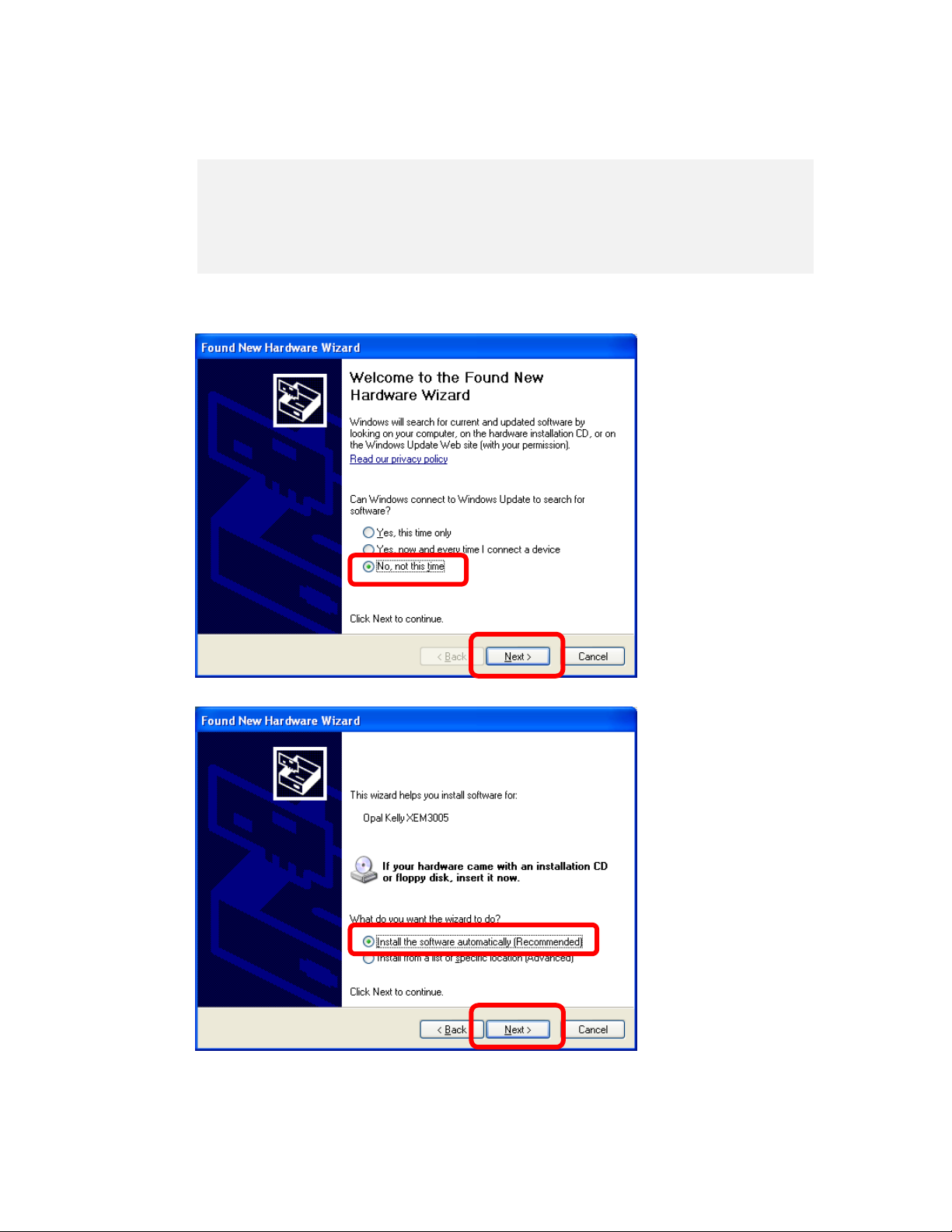
The first time you
connect the amplifier to
your computer, “Found
New Hardware Wizard”
will launch, and you will
see this screen. Select
“No, not this time”, and
click “Next”.
Select “Install the
software automatically”,
and click “Next”.
1
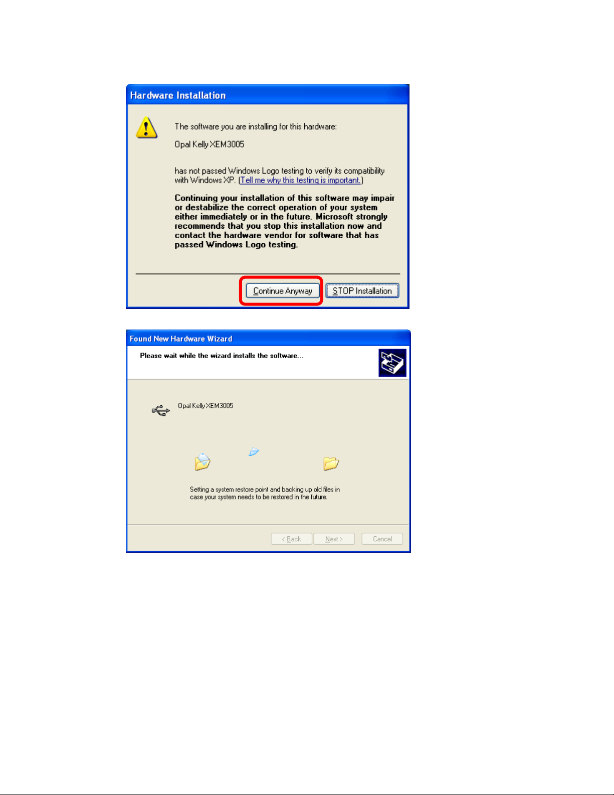
If this screen pops up,
click on “Continue
Anyway”.
You will see this screen
as the amplifier gets
installed on your
computer.
11
 Loading...