


Total Energy Controls
TEC 100/200 Programming
& Installation Manual
As of software v7.2

Contents
2
Installation Instructions
General Notes 3
Mains Wiring 3
Control Wiring 4
Other Wiring Options 5
Fitting and Wiring Temperature Sensors 6
Temperature Display Calibration 8
Commissioning Instructions
Keypad Overview 9
Establishing the System Max Flow Temp 11
Setting the Programs 12
Setting the Calendar 12
Programming the On / Off Times 14
Frequency (How the Time Clock works) 16
Select Days 17
Optimise On Time 18
Setting the Maximum Flow Temperature 20
Setting the Minimum Flow Temperature 21
Setting the Minimum Return Temperature 22
Setting the Mid Temperature 23
Setting the Night Temperature 24
Setting the Frost Temperature 25
Setting the External Cut-Off Temperature 26
The Plant Relay 27
Hot Water Priority 28
Internal / External Optimisation 29
Calibration 30
Rotation 32
Exiting Programming Mode 33
TEC 100/200 with Monitoring Socket
Monitor Installation and Operation 34
Description Page
Introduction 9
Optimise Off Time 19

Installation
General Notes
The installation of all TEC units should be carried out by a qualified electrical
engineer familiar with heating systems and control wiring.
All control circuits of TEC units are ‘volt free’ and may be used to switch
240V AC or low voltage control systems.
Extreme care must be taken to ensure that all wiring is correct before applying
power, as irrepairable damage to the PCB could result due to incorrect
connections.
Mains Wiring
Unscrew the four screws of the TEC 100/200 and remove the lid to gain access
to the PCB and wiring connections.
A 240V AC 1Ph 50Hz supply may be taken from the existing time clock
switched or permanent supply, or direct from the boiler mains input connections
(where available), which ever is the most suitable. The 240V connection to the
TEC 100/200 is shown in Fig.1 below.
3
TEC 100/200 PCB
Fig. 1
240 V Supply as described
E L
N

)
4
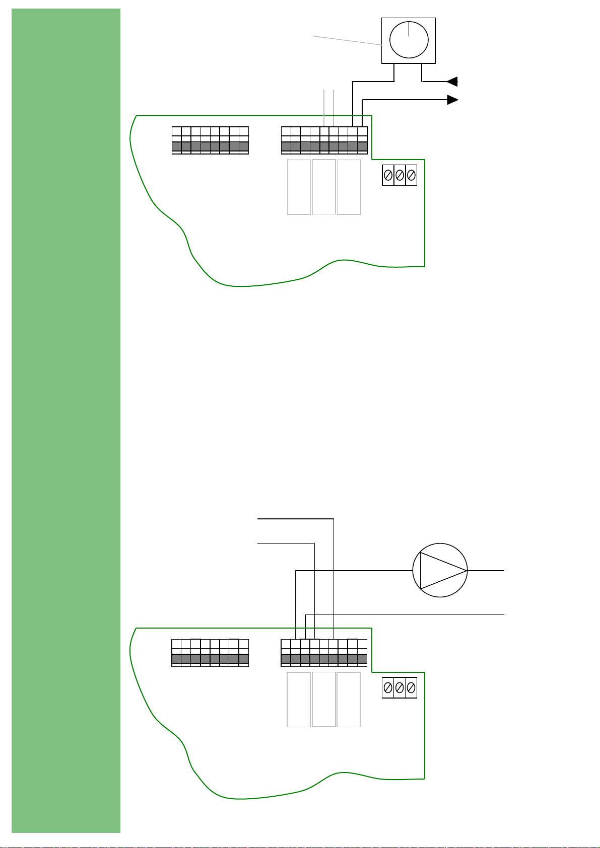
Control Wiring
NOTE: If a wiring harness is provided in the rear of the enclosure please
follow cables to TEC 100/200 PCB to determine connections as described in
the following sections.
Many boilers are provided with an accessible mains terminal block. Most
have a pair of connections (usually unused) for use with external controls.
These connections will have a link which needs to be removed so that the
TEC 100/200 control wires can be connected as shown in Fig.2.
Remove link
To boiler 2 (TEC 200
To boiler
N L
E
TEC 100/200 PCB
If the boiler is a simple
permanent pilot type, i.e.
Ideal Concord, Potterton,
Kingfisher etc, the
connections may be made
into the mains supply of
the boiler if more
convenient.
Fig. 2
Note: A 5-core heat resistant flex is ideal for connecting the TEC 100/200 to the
boiler. The recommended connection method is via a flexible nylon
conduit to house the cable.
Where a terminal block arrangement as shown in Fig.2 is not available, the
control wiring should be connected directly into the boiler thermostat wiring
as shown in Fig.3.
p
Boiler Thermostat
Boiler 2 (TEC200):
Connections as per
Boiler 1
Live in
Live to Burner
ut
5
N L
E
TEC 100/200 PCB
Fig. 3
Other Wiring Options
The TEC 100/200 has three control relays. On the TEC 100 the left hand relay
is the Plant Relay which may be used to control a circulating pump and the
right hand relay is the boiler control circuit. The centre relay (Tec 100 only)
make and breaks on RTN/HW settings and may be used to control a HW pump,
solenoid etc, see Fig 4. On the TEC 200 the left hand relay is the Plant Relay,
the middle relay is boiler 2 control circuit and the right hand relay is boiler 1
control circuit.
Make on
RTN/HW
temperature
drop.
TEC 100/200 PCB
Pump
Neutral
Live
1 P 2
E
N L
Fig. 4

6
Fitting and Wiring Temperature Sensors
The TEC 100/200 has three temperature sensor inputs, these being Flow,
Return/Hot Water and External. Connections are as shown in Fig.5.
FLOW Sensor
RETURN / HW Sensor
EXTERNAL Sensor
Aux Extn Flow Retn
P 2 1
N E L
TEC 100/200 PCB
Fig. 5
Flow / Return Temperature Sensors (Cable Type)
Using heat resistant cloth tape, tightly strap the sensors to the relevant
flow and return pipes, close to boiler, before any branching connections.
Cover the sensors with heating pipe insulation and strap with ty-wraps or
similar. See Fig.6.
Heat Resistant Cloth Tape
Securing Ty-Wraps
Sensor Head
Pipe Insulation fixed over Sensor
Flow / Return Pipe
Fig. 6

connections
7
Optional Hot Water Tank Sensor connections (replaces Return Temperature
Sensor) are shown in Fig.7.
Optional HW Tank Sensor.
Connect in place of Return
Temperature Sensor.
Mount 1/3 to 1/2 way up
Fix Tank Sensor
with expanding
wire (supplied
with optional
Tank Sensor).
TEC 100/200 Return
Temperature Sensor
Fig. 7
If the hot water tank is a distance from the boiler, wiring to it may be
impractical.
If hot water priority is important then the Return Sensor should be fitted
to the Hot Water Tank Return Pipe. If this is also impractical, then fit
as normal to the main Return Pipe and set the Minimum Return
Temperature to provide an adequate level of hot water supply.
Where the tank option is used, set the Minimum Return Temperature
to the stored water temperature requirement.
External Sensor
The External Sensor should preferably be positioned on a north facing
exterior wall, and connected to the appropriate terminals of the TEC 100/200.
If it is not possible to mount the sensor on a north facing wall, then mount
in a shaded position, under eaves, and away from boiler house vent grilles etc.
Note A special reflective, insulated external sensor is available when fitting
in a position where solar heat is unavoidable.

8
Temperature Display Calibration
When required, the temperatures as displayed on the TEC 100/200 may be
adjusted to cater for heat losses on pipework, losses on external temperature
sensor etc. Program 17 (see page 30) can be used to calibrate the temperature
display by -10ºC/+20ºC.

C
ommissioning - Introduction
9
The TEC 100/200 Digital has 18 main programs, these being:
1. Calendar
2. On/Off Times (Two On/Off Periods per day)
3. Frequency (Once, Twice, 24 Hours)
4. Select Days (Every Day, Weekends, Week Days)
5. Optimise On Time ( 0 to 240 minutes)
6. Optimise Off Time ( 0 to 240 minutes)
7. Maximum Flow Temperature (30ºC to 85ºC)
8. Minimum Flow Temperature (25ºC to 85ºC)
9. Minimum Return Temperature (20ºC to 65ºC)
10. Mid Temperature (0ºC to 85ºC)
11. Night Temperature (0ºC to 85ºC)
12. Frost Temperature (0ºC to 35ºC)
13. External Cut Off Temperature (0ºC to 35ºC)
14. Differential (1ºC to 5ºC)
15. Hot Water Priority (Yes / No)
16. Internal/External Optimisation (Yes / No)
17. Calibration (-10ºC/+20ºC)
18. Rotation (Yes / No)
Certain Differentials and the Compensation Slope are fixed within the software,
i.e. Return Temp 2ºC, External Temp 2ºC, Compensation Slope 1.5.
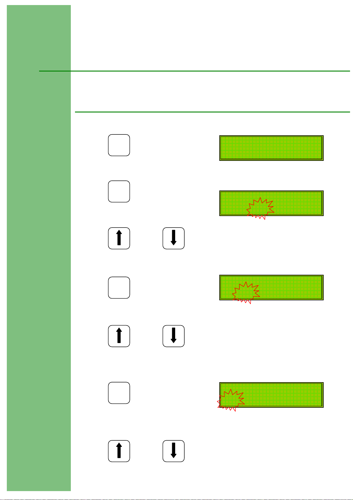
Keypad and Running Mode Overview
Used to enter Programming Mode from normal running mode,
P
and to access Change Mode for the selected program.
PROGRAM
Used to cycle through the program list when in Programming
Mode and to change program settings when in Change Mode.
SELECT
RETURN
Used to cycle through the program list when in Programming
Mode and to change program settings when in Change Mode.

10
Used to confirm a programming change and to exit from the
E
ENTER
The TEC 100/200 will go into Boost mode from a cold
start. It will stay in this mode for 15 minutes, or
until the Return Temp is within10ºC of the Flow
Temp If a Hot Water Sensor is fitted then the
TEC 100/200 will go into Boost mode if the HW Tank
is cold.
Firing mode indicates that the boiler is firing.
Temp Set indicates that the actual Flow Temp is
above the system set temperature**. The boiler will
not be firing at this point.
Economising indicate that the TEC 100/200 has entered
self learning mode and is making economies. The
boiler will not be firing at this point.
Ext ‘flashing’ indicates that the external temp
is above the level set in the Ext Cut-Off program.
Programming Mode.
BOOST
S57 F20 R20 E12
FIRING
S57 F50 R42 E12
TEMPERATURE SET
S57 F59 R53 E12
ECONOMISING
S57 F59 R53 E12
EXT
S57 F36 R34 E16
** The system set temperature as indicated in the display, represents the
heating system aiming temperature based on current climatic conditions,
as determined by the TEC 100/200’s weather compensation circuitry.

11
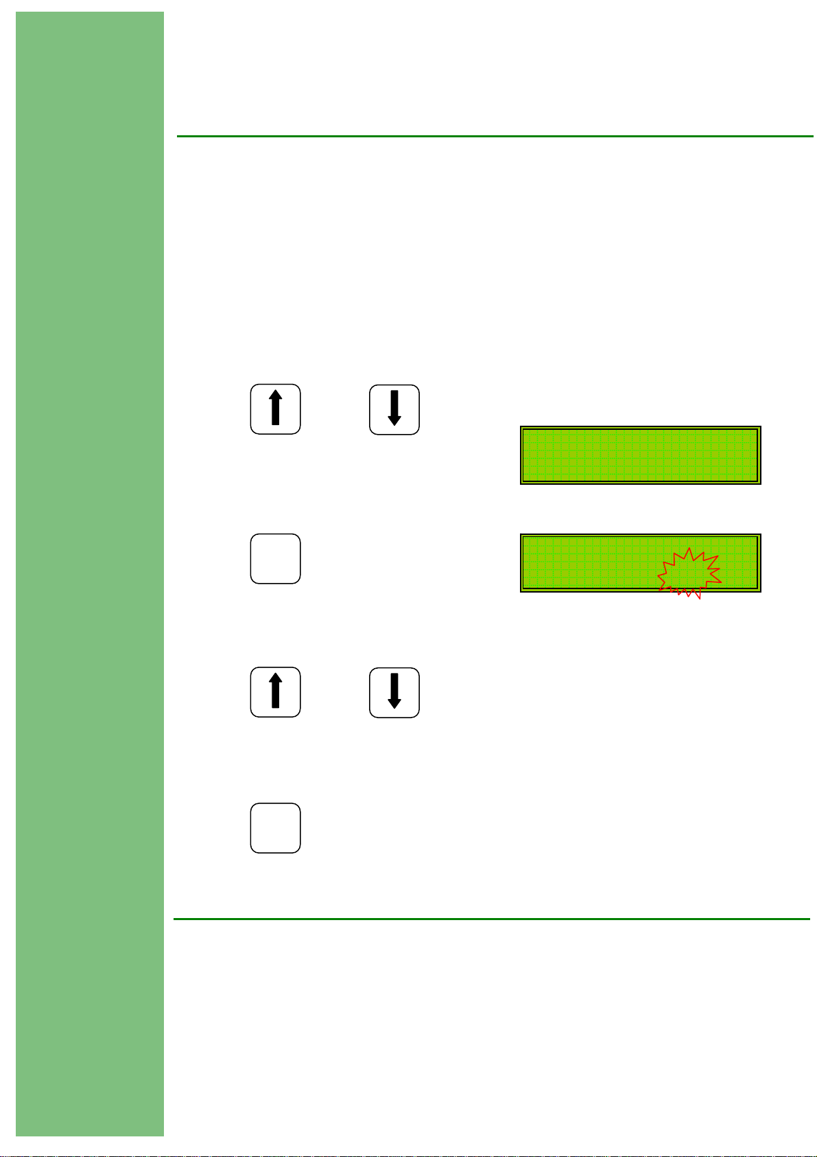
Establishing the System Maximum Flow Temp
Switch on the power to the TEC 100/200.
1. Set the Bypass Switch to the bypass position.
Allow the heating system to cycle twice at the normal winter setting of the
boiler thermostat (see plant engineer, caretaker, maintenance manger etc to
establish winter thermostat position).
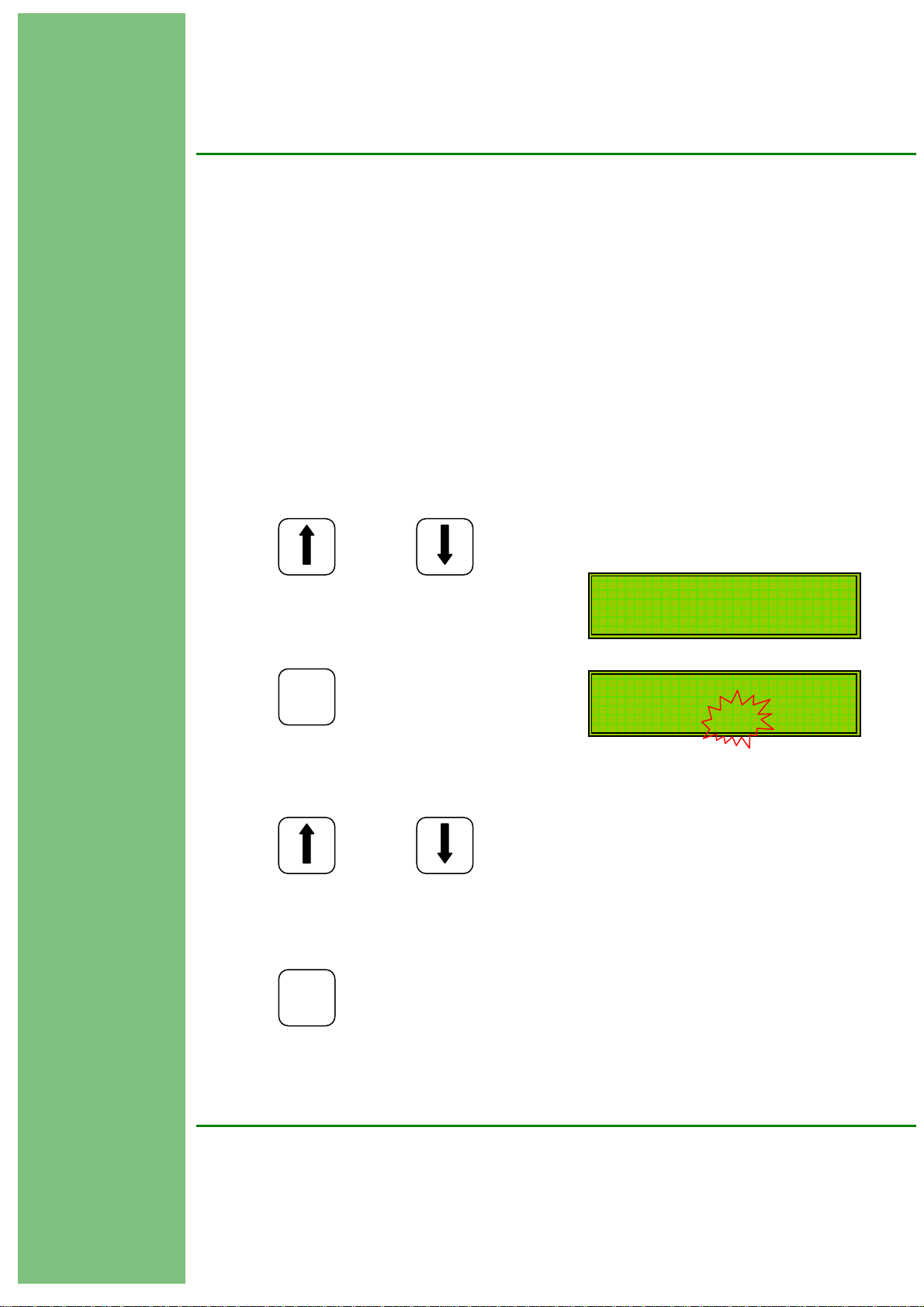
2. The display will show:
3. When the actual Flow Temperature exceeds the Set Temperature, the display
will change:
4. When the boiler has cycled twice with the TEC 100/200 in bypass, observe the
actual flow temperature as shown on the display:
In this example, the winter setting for the heating system (TEC 100/200
maximum flow setting) should be set to 72ºC (73ºC - 1ºC).
The Boiler Thermostat should now be set to a higher setting to ensure correct
operation of the TEC 100/200.
Actual Return / HW Temp
Actual External Temp
Current Mode
Set Temp
Actual Flow Temp
FIRING Tu 10:05
S57 F50 R42 E05
TEMP.SET Tu 10:05
S57 F58 R48 E05
TEMP.SET Tu 10:05
S57 F73 R65 E05
Setting the Programs
P1. Setting the Calendar (Factory Set)
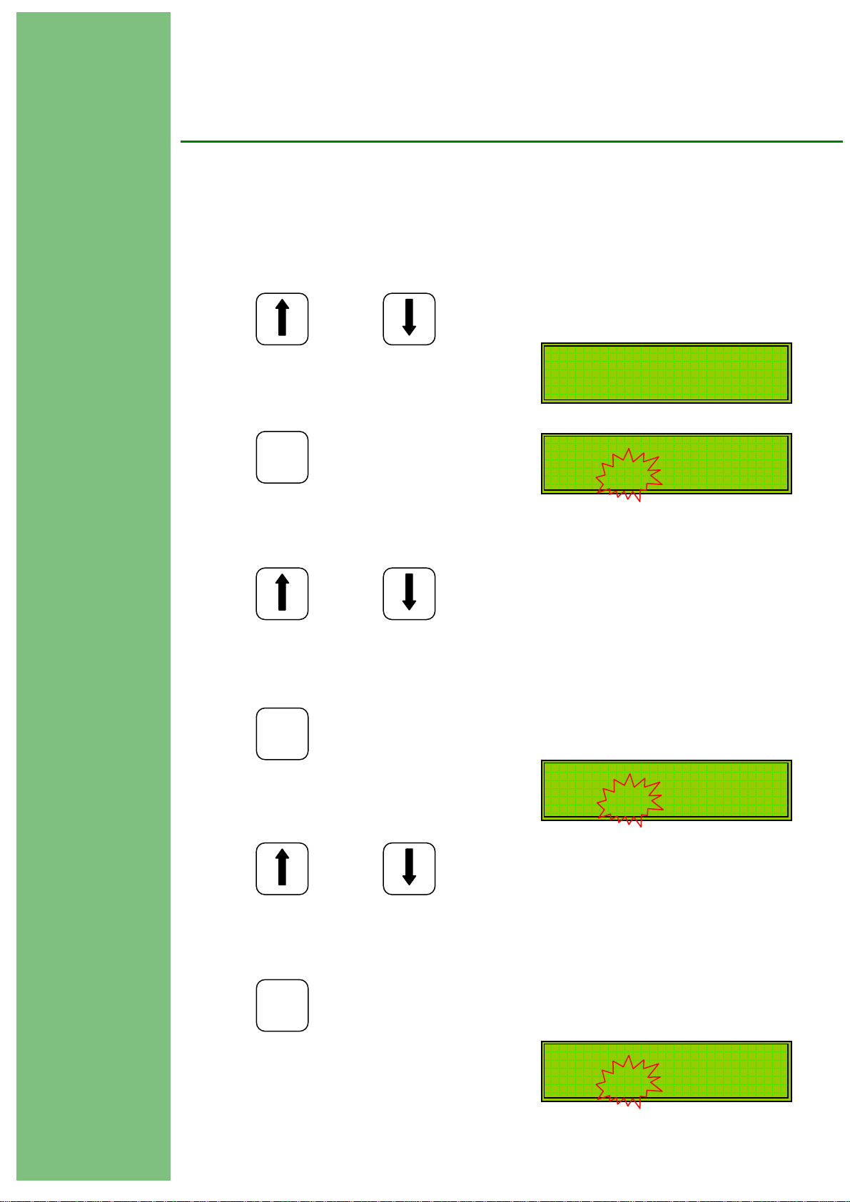
1. Press to change display to:
2. Press again to display:
3. Press or to set the year.
4.
Press to change display to:
5. Press or to set the month.
Press to change display to:
6.
7. Press or to set the date.
P
PROGRAM
P
PROGRAM
RETURN SELECT
E
ENTER
RETURN SELECT
E
ENTER
12
1 CALENDAR
21/11/03 11:29
SET YEAR
21/11/03 11:29
SET MONTH
21/11/03 11:29
SET DATE
21/11/03 11:29
RETURN SELECT

8.
Press to change display to:
9. Press or to set the hour.
8.
Press to change display to:
9. Press or to set the minutes.
10.
Press to change display to:
11. Press or to set the day.
Press to confirm the program change and return to main menu.
12.
Press to advance to next program.
13.
E
ENTER
SELECT RETURN
E
ENTER
SELECT RETURN
E
ENTER
SELECT RETURN
E
ENTER
SELECT
SET HOUR
21/11/03 11:29
SET MINS
21/11/03 11:29
SET DAY Fr
13

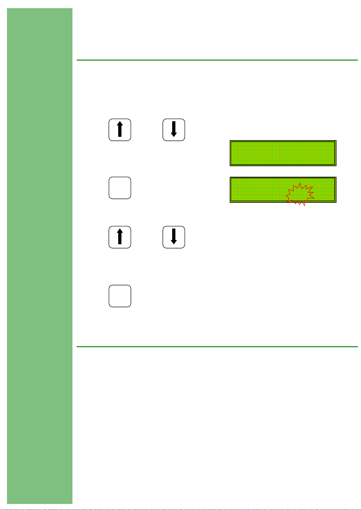
P2. Programming the Time Clock (On/Off Times)
1. Press or to select program 2:
2. Press again to display:
There are two (2) programmable On/Off times per day.
The second OFF time must ALWAYS be programmed, and set to a time
after, but in the same 24 hour period as the first ON time.
3. To change On/Off Times select the required day with
4. Press to enter programming mode for the chosen day:
5. Press to set first ON time:
6. Press or to set the hour as required.
7. Press to set first ON time minutes:
SELECT RETURN
P
PROGRAM
P
PROGRAM
P
PROGRAM
SELECT RETURN
2 ON/OFF TIMES
MO 1 07:30-00:00
2 00:00-16:30
SELECT RETURN
MO 1 07:30-00:00
* 2 00:00-16:30
MO 1 07:30-00:00
* 2 00:00-16:30
14
E
ENTER
MO 1 07:30-00:00
* 2 00:00-16:30

8. Press or to set the minutes as required.
9. Press to set first OFF** time:
** If the FIRST OFF time is not required leave at 00:00.
Adjust HOUR and MINUTES in the same way as previously described.
10. Press to set the second ON time and repeat as above.
11. Press to set the second OFF time and repeat as above.
If different On/Off times are required for each day, then repeat the above
instructions for each day’s times.
To repeat a days On/Off times into the next day, select the next day as
described above and press followed by .
12.
Press to confirm program changes and return to main menu.
SELECT RETURN
E
ENTER
E
ENTER
E
ENTER
PROGRAM ENTER
E
ENTER
P
MO 1 07:30-00:00
* 2 00:00-16:30
E
15

16
P3. Frequency (How the Time Clock operates)
1. Press or to select program 3:
2. Press to display:
3. Press or to set as described below:
ONCE The time clock operates from the first ON time to the second
OFF time.
TWICE The time clock operates on both ON and OFF times i.e. two
On/Off periods per day.
24 HOUR The time clock operates 24 hours a day regardless of the
On/Off settings.
4.
Press to confirm program changes and return to main menu.
SELECT RETURN
P
PROGRAM
SELECT RETURN
E
3 FREQUENCY
CURRENT ONCE
UP/DN TO CHANGE
CURRENT ONCE
ENTER

P4. Select Days
1. Press or to select program 4:
2. Press to display:
3. Press or to set as described below:
EVERY DAY The heating will operate everyday as set by the time
clock On/Off times.
WEEK ENDS The heating will operate at week ends only as set by
time clock On/Off time for Sat – Sun. If reduced
heating is required at week ends then set the time clock
for reduced hours during Saturday and Sunday, and then
set program 4 to EVERY DAY.
WEEK DAYS The heating will operate during week days only as set
by the time clock On/Off times Mon – Fri. The heating
will be OFF at weekends.
4.
Press to confirm program changes and return to main menu.
SELECT RETURN
P
PROGRAM
RETURN SELECT
4 SELECT DAYS
CURRENT EVERY DAY
UP/DN TO CHANGE
CURRENT EVERY DAY
E
17
ENTER

18
P5. Optimise On (Pre-Heat)
1. Press or to select program 5:
When programming a Variable Pre-Heat period (Optimum On) the first switch
on time (P2) should be set to the buildings occupation time. If a variable pre-
heat period is not required, then the first switch on time must allow for a
sufficient warm-up period before occupation time.
When selected, the full programmed variable pre-heat period will occur at 0ºC
external temperature. At temperatures above 0ºC the system will calculate the
required pre-heat time.
Note: To assure adequate temperatures are achieved by occupation time
If Optimum On is not required then set to 000 mins.
2. Press to display:
3. Press or to set the required number of minutes.
4.
Press to confirm program changes and return to main menu.
SELECT RETURN
5 OPTIMISE ON
CURRENT 000 MINS
the maximum pre-heat period must satisfy the building’s thermal
characteristics.
UP/DN TO CHANGE
P
PROGRAM
SELECT RETURN
CURRENT 000 MINS
E
ENTER

19
P6. Optimise Off
1. Press or to select program 6:
Optimum Off periods will, when selected, switch off a boiler / heating system
earlier than the programmed off time.
At 15ºC external temperature the full optimum off period will occur and the
boilers will switch off early. At 0ºC external temperature there will be no
optimum off and the boilers will switch off at the normal programmed time. At
external temperatures between 0ºC and 15ºC the system will calculate the
required off time.
If Optimum Off is not required then set to 000 mins.
2. Press to display:
3. Press or to set the required number of minutes.
Press to confirm program changes and return to main menu.
4.
P
PROGRAM
E
RETURN SELECT
6 OPTIMISE OFF
CURRENT 000 MINS
UP/DN TO CHANGE
CURRENT 000 MINS
RETURN SELECT
ENTER

P7. Setting the Maximum Flow Temperature
2. Press to change display to:
3. Press or to change the temperature setting to that
required (i.e. 73ºC).
4. Press to confirm the program changes and return to main menu.
1. Press or to select program 7:
SELECT
P
PROGRAM
SELECT
RETURN
RETURN
7 MAX FLOW TEMP
CURRENT 60
UP/DN TO CHANGE
CURRENT 73
E
ENTER
20

P8. Setting the Minimum Flow Temperature
2. Press to change display to:
3. Press or to change the temperature setting to that
required.
4. Press to confirm the program changes and return to main menu.
1. Press or to select program 8:
SELECT
P
PROGRAM
SELECT
RETURN
RETURN
8 MIN FLOW TEMP
CURRENT 40
UP/DN TO CHANGE
CURRENT 40
E
ENTER
Setting a Minimum Flow Temperature is required to limit the effect of the
Compensation. The flow temperature will not fall below that set in the
Minimum Flow program ( - differential), even if the compensated flow
temperature is below this level.
The Minimum Flow Temperature should be chosen to meet heating criteria.
21

P9. Setting the Minimum Return Temperature
The Minimum Return temperature will depend on the type of heating system:
Heating and Hot Water.
Where convenient, the return temperature sensor should be fitted to the hot
water storage tank (see installation instructions), the hot water return pipework
or the hot water circulating pipework.
The minimum return temperature should be set to provide normal hot water
tank temperature, i.e. 60ºC.
Heating Only.
In this instance, the minimum return temperature should be set to the boiler
manufacturers recommended level, i.e. 55ºC for oil fired systems, 50ºC or lower
for gas fired systems. These figures are examples only. Refer to your boiler
manual for manufacturer recommended settings.
1. Press or to select program 9:
2. Press to change display to:
3. Press or to set the required temperature.
4. Press to confirm program changes and return to main menu.
SELECT
P
PROGRAM
SELECT
E
ENTER
RETURN
RETURN
9 MIN RETN TEMP
CURRENT 50
UP/DN TO CHANGE
CURRENT 55
22

23
P10. Setting the Mid Temperature
The Mid Temperature is used (if required) to set the flow temperature during
st
the period between the 1
Off Time and the 2nd On Time.
If a second On Period is not required, then set Frequency (P3) to Once.
1. Press or to select program 10:
SELECT
RETURN
10 MID TEMP
CURRENT 65
2. Press to change display to:
P
PROGRAM
UP/DN TO CHANGE
CURRENT 65
3. Press or to set the required temperature.
SELECT
RETURN
4. Press to confirm program changes and return to main menu.
E
ENTER
24
P11. Setting the Night Temperature
The Night Temperature can be used in 2 ways:
1. To provide basic frost protection in conjunction with the frost
temperature (P12).
2. To provide night time economies on 24 hour systems by selecting
a lower flow temperature during the programmed off periods.
1. Press or to select program 11:
2. Press to change display to:
3. Press or to set the required temperature.
4. Press to confirm program changes and return to main menu.
SELECT
P
PROGRAM
SELECT
RETURN
RETURN
11 NIGHT TEMP
CURRENT 35
UP/DN TO CHANGE
CURRENT 35
E
ENTER

25
P12. Setting the Frost Temperature
The Frost Temperature can be set to cancel the Night Temperature (P11)
at a programmed external temperature.
E.G. For frost protection only set P12 to say 1ºC.
The night temperature will not be activated until the external temperature falls
to this level.
If the unit is installed in a nursing or residential home it may be possible to set
P12 to 15ºC - 16ºC so that the night temperature will not be activated at
temperatures above this and the heating will switch off.
If night temperature is required whatever the external temperature, set P12 to
maximum, i.e. 35ºC. Discuss this aspect with the building manager / owner to
establish the requirements.
Operation of the Frost Temperature will cancel 24 Hr Hot Water Priority.
1. Press or to select program 12:
2. Press to change display to:
3. Press or to set the required temperature.
4. Press to confirm program changes and return to main menu.
SELECT
P
PROGRAM
SELECT
RETURN
RETURN
12 FROST TEMP
CURRENT 03
UP/DN TO CHANGE
CURRENT 03
E
ENTER

13. Setting the External Cut-Off Temperature
The External Cut-Off Temperature sets the outside temperature above which
the heating system will switch off. This setting is also referred to as the
Summer Cut-Off Temperature. The heating will come back on at 2ºC below the
External Cut-Off Temperature.
1. Press or to select program 13:
2. Press to change display to:
3. Press or to set the required temperature.
4. Press to confirm program changes and return to main menu.
SELECT RETURN
P
PROGRAM
SELECT RETURN
E
ENTER
13 EXT C/O TEMP
CURRENT 35
UP/DN TO CHANGE
CURRENT 35
26
27
14. Differential
The Differential should be set to match existing boiler thermostat cycling
temperature.
1. Press or to select program 14:
2. Press to change display to:
3. Press or to set required differential.
4. Press to confirm program changes and return to main menu.
SELECT RETURN
P
PROGRAM
RETURN SELECT
E
ENTER
14 DIFF
CURRENT 2
UP/DN TO CHANGE
CURRENT 2

28
P15. Hot Water Priority (24 Hour)
1. Press or to select program 15:
2. Press to change display to:
3. Press or to set YES, NO or HW Only.
4. Press to confirm program changes and return to main menu.
When set to NO the TEC 100/200 Hot Water Priority operates during the
programmed ON periods.
When set to YES, 24 hour hot water priority is provided.
When set to HW ONLY the plant relay controlling the heating pump will
switch off when the external cut-off temperature is exceeded. This may only
be set if a separate HW pump is installed, or gravity flow to the hot water
cylinder is used.
Note: The centre relay of the TEC 100 is programmed to operate at the
RTN/HW temperature setting and may be used to control the HW pump etc.
Consideration should be given to the Night Temperature when setting Hot
Water Priority. It should also be noted that operation of the Frost
Temperature can cancel 24 Hour Hot Water Priority.
P
PROGRAM
E
ENTER
RETURN SELECT
RETURN SELECT
15 HW PRIORITY
CURRENT NO
UP/DN TO CHANGE
CURRENT NO
29
P16. Internal / External Optimisation
Program 16 allows the TEC 100/200 to utilise either Internal AND External
Optimisation or just External Optimisation.
Internal Optimisation requires the heating pump to be connected to the
Plant/Pump Relay as described on page 5.
To use both modes of Optimisation set to YES.
To use just External Optimisation set to NO.
1. Press or to select program 16:
2. Press to change display to:
3. Press or to set YES or NO.
4. Press to confirm program changes and return to main menu.
SELECT RETURN
P
PROGRAM
SELECT RETURN
E
16 INT&EXT OPTIM
CURRENT NO
UP/DN TO CHANGE
CURRENT NO
ENTER
30
P17. Calibration
Program 17 allows individual calibration of the Flow, Return and External
temperature sensors. Each sensor reading can be adjusted by -10ºC/+20ºC.
1. Press or to select program 17:
2. Press to change display to:
3. Press or to adjust the displayed temp (-10ºC/+20ºC).
4. Press to confirm program changes and display:
5. Press or to adjust the displayed temp (-10ºC/+20ºC).
6. Press to confirm program changes and display:
SELECT RETURN
P
PROGRAM
SELECT RETURN
E
ENTER
SELECT RETURN
E
17 CALIBRATE
17 CALIBRATE
FLOW 60
17 CALIBRATE
RETN 50
ENTER
17 CALIBRATE
EXTN 16

7. Press or to adjust the displayed temp (-10ºC/+20ºC).
8. Press to confirm program changes and return to main menu.
SELECT RETURN
E
ENTER
31

32
P18. Rotation (TEC 200 only)
Program 18 allows the TEC 200 to rotate the lead boiler every 24 hours.
When set to YES the lead boiler is changed at midnight i.e. boiler 1 leads one
day, and boiler 2 the next, then boiler 1 next etc etc.
When set to NO the boiler connected as boiler one will always be the lead
boiler.
1. Press or to select program 18:
2. Press to change display to:
3. Press or to set YES or NO.
4. Press to confirm program changes and return to main menu.
SELECT RETURN
P
PROGRAM
SELECT RETURN
E
18 ROTATION
CURRENT YES
UP/DN TO CHANGE
CURRENT NO
ENTER

33
Exiting Programming Mode
To exit from the programming mode, first ensure that the display indicates
you are in the main menu.
At this point, press to exit programming mode.
The display will change to:
And then, after a few seconds to:
The display may show slightly different information depending on the
current mode of operation, i.e. boost, firing, economising etc.
Note: When in programming mode the TEC 100/200 will revert to
normal
running mode if the keypad is not operated for a period of 30
seconds (4 minutes if in program change mode).
To access programming mode from normal running mode:
Press and then select required program with .
Make any program changes as described previously.
P
PROGRAM SELECT RETURN
E
ENTER
TEC 100 V3
ACTIVE
FIRING Tu 15:35
S57 F50 R42 E05

TEC 100/200 with Monitor Socket
The TEC 100/200 is available with a pre-wired Monitoring Socket. In such a
case, the control wiring must be as shown in Fig.3 (page 5).
The power supply to the unit must be from a permanent source to enable the
monitoring system to function in the correct manner.
Within the TEC 100/200 you will see an orange fly lead. This should be
connected to the timeswitch output to provide a signal for the demand meters
(lower set).
If for any reason the system will not allow connections into the control
thermostat as shown in Fig.3, then remove the red link wire as shown in Fig.9.
Connect the white fly lead to the now spare connector on the monitor socket
(originally connected to red link), and connect directly to burner supply to
provide a signal for the firing meters (upper set).
The monitoring system has an integral digital timer that has been programmed
to operate the Day On/Day Off changeover at 00:05 – 00:10 hrs. Open the
monitor lid and operate the change button on the digital timer to initiate an
active period (red LED off).
With the boiler firing and the heating timeswitch on, the two active meters
should be operating. The top active meter indicating firing hours, and the
bottom active meter indicating demand hours.
If they are not operating, re-check all connections.
Allow the TEC 100/200 to reach Temp Set mode (boiler cut-off), and note the
firing meter has stopped. Operate the change button on the digital timer to
initiate a bypass period (red LED on). Providing that the boiler thermostat
is on, the boiler will re-fire (TEC 100/200 bypassed), and the bypass meters
will operate. The top bypass meter indicating firing hours, and the bottom
bypass meter indicating demand hours.
When ready to start the monitored test, operate the change button on the
digital timer to enter an active period (red LED off), ensuring that the timer is
itself in the off state. If necessary, reset the hour meters to zero with the reset
button provided in the top right hand corner of the unit. The system will now
34

35
record firing and demand hours in both active and bypass modes. These
modes will alternate on a day to day basis.
To PCB
0.0
ACTIVE
0.0
BYPASS
0.0
ACTIVE
0.0
Remove RED link from
here and connect white fly
lead in it’s place. Connect
the other end of the white
fly lead direct to the burner.
Firing Meters
Demand Meters
BYPASS
Flashing indicator when operating
Fig. 9
Monitor
 Loading...