

Page 1
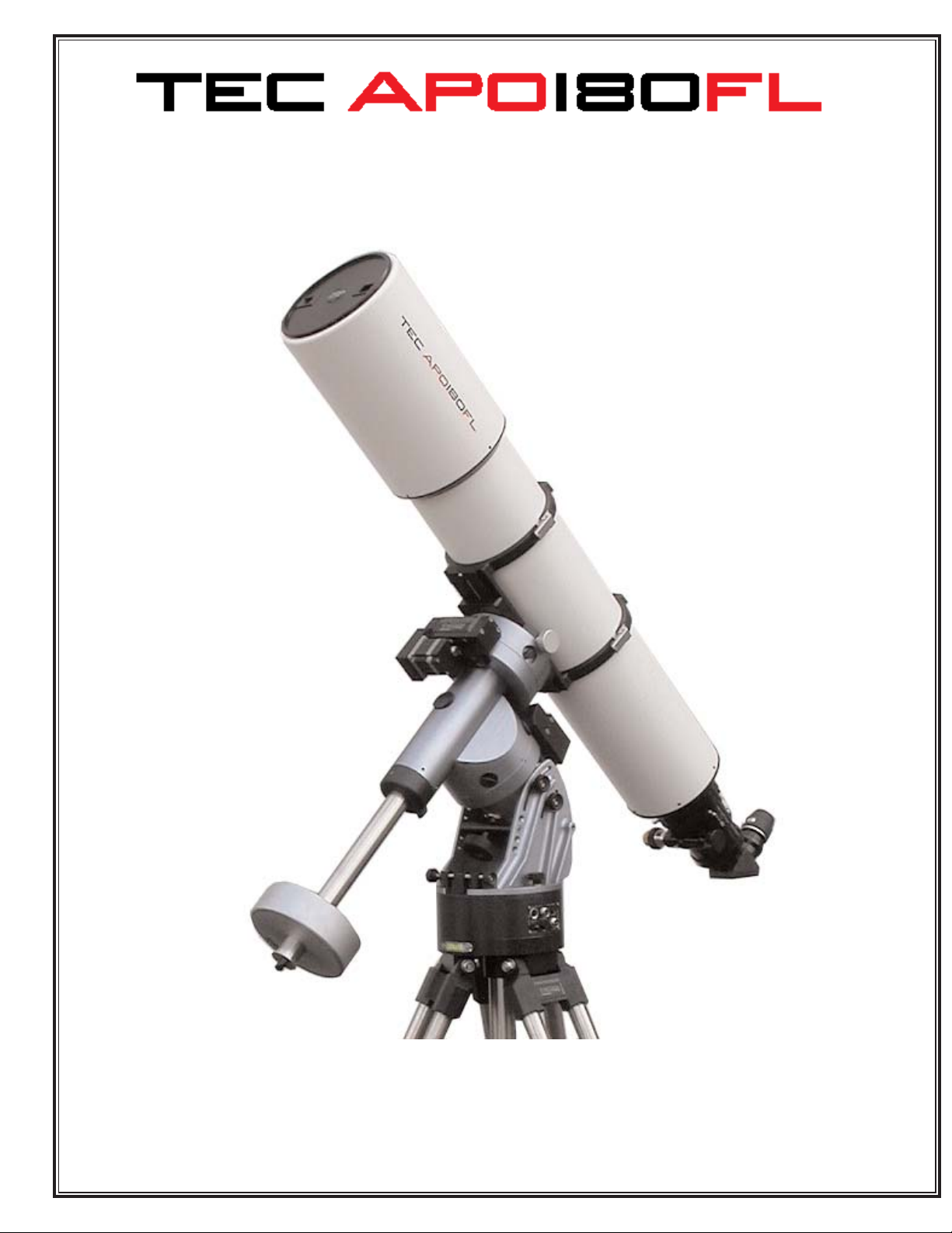
OWNER’S MANUAL
2006
Page 2

IMPORTANT - PLEASE READ THIS MANUAL BEFORE USING YOUR TELESCOPE
SAFETY WARNINGS
Do not look at the sun through the telescope!
Viewing the sun through the telescope without special equipment (Solar Filters) will cause permanent
visual impairment and telescope parts damage.
Do not disassemble!
Disassembly of telescope could result in personal injury and telescope malfunction.
CONTACT INFORMATION
If you have any questions or need assistance - please contact us:
Phone: 303 273 9322 • Fax: 303 273 0204
E-mail: [email protected] • Web site: www.telescopengineering.com
User’s group site: http://groups.yahoo.com/group/tec-scopes
Address: Telescope Engineering Company • 15730 West 6-th Ave. Golden CO, 80401. USA
OPTIONAL EQUIPMENT (see www.telescopengineering.com for the current prices)
Tube rings (extra or replacement) $360
Finderscope bracket with base $120
8x50 finder with illuminated reticle (Japan) $140
AP finder bracket $60
TEC 12” dovetail plate $90
Eyepiece Turret $500
Mahogany case for I-Turret $150
Field Flattener $750
Adapter for large format CCD camera $50
1
TEC APO 180 TECHNICAL SPECIFICATIONS
Clear aperture 7” / 180 mm
Focal ratio 7.0
Focal length 1260 mm
Image scale 2.7 arc min/mm
Field curvature 450mm
Resolution (theoretical) 0.66 arc sec
Focuser Feather Touch 3545
Eyepiece holder 2” Collet type
Focusing range 4.5” / 114 mm
One turn focus travel Coarse 21.5 mm / Fine 2.3 mm
Back focus distance 7” / 180 mm
Focuser load capacity 10 lb
Tube assembly diameter 8” / 201 mm
Dew shield dia. 9.2” / 234 mm ?
TA length (shortest) 45” / 1140 mm
Balance point position 20” from focuser’s flange
OTA weight 36.5 lb / 16.5 kg *
Lens coatings: Broad band 5 layer antireflection coating (BBAR)
Price (2006) $18,000
Price includes : Optical tube assembly, front cover, plug, tube rings and case.
*for tube rings and TEC 12”dovetail plate - add 3.5 lb.
Page 3
OVERVIEW
This manual has been written to help you enjoy using your TEC APO 180 refractor.
The APO 180 has number of features that in a given combination are rarely found in one scope:
Precision apochromatic objective with modern coating that makes lenses almost invisible.
Retractable Dew Shield. Light weight tube assembly. FeatherTouch 360° rotatable focuser with coarse and
fine focusing. Collet type eyepiece holder.
Line of accessories, including::
Precision tube rings with adjustable latches
Dovetail plate (same width and fit as Losmandy plates)
Finder bracket with new principle of finder adjustment with two thumb screws only.
Field Flattener with adapter for large CCD cameras (STL of SBIG).)
ALL
PARTS OF THE TELESCOPE, INCLUDING: OPTICS, COATINGS, ETC. ARE MADE IN THE USA.
GETTING TO KNOW YOUR TELESCOPE
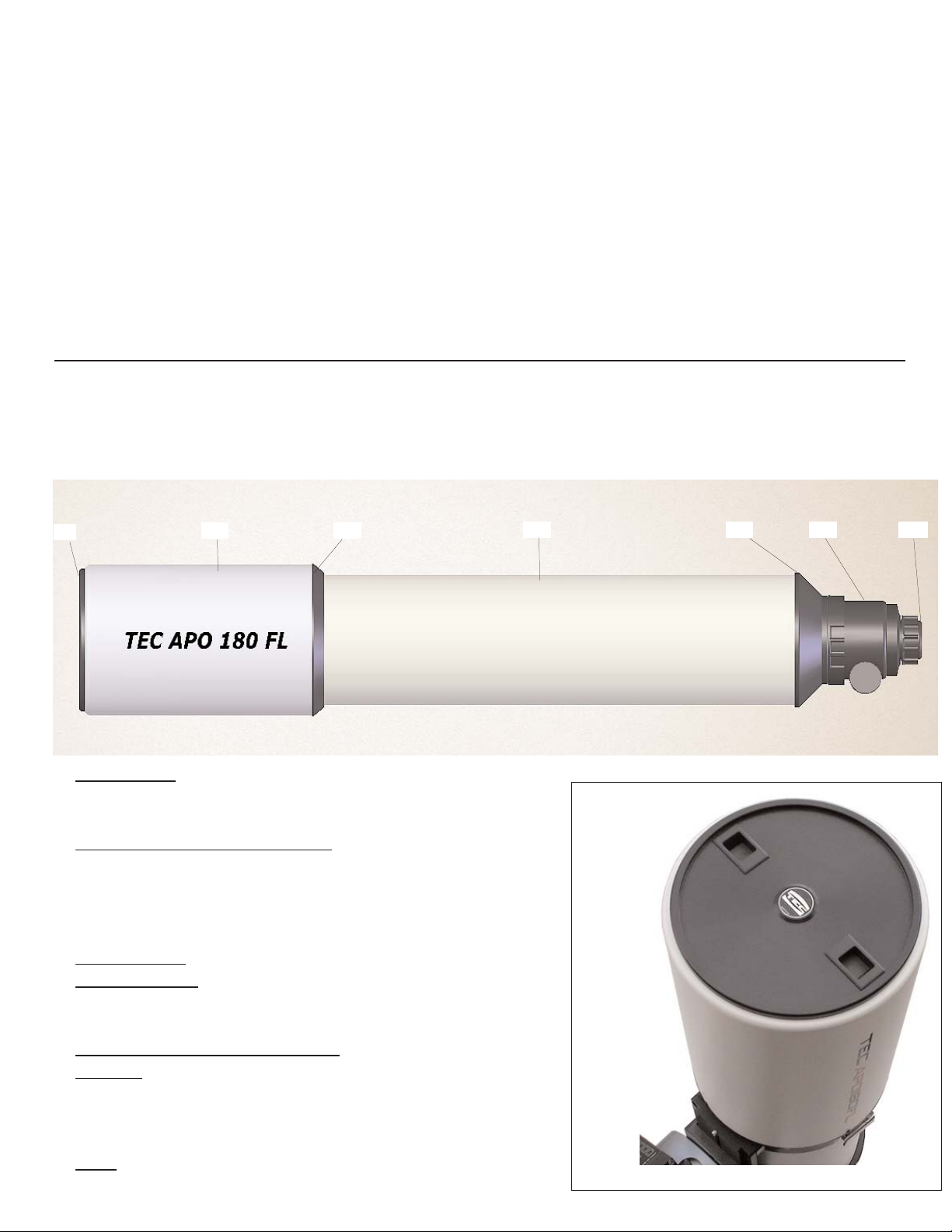
The parts of the telescope and their functions are identified and described below.
1 Front Cover
. - black anodized mashined Aluminum with
push-pull spring loaded latches. It protects the optics and holds
the dew shield during transportation.
2 Retractable Sliding Dew Shield.
This feature makes the OTA
shorter for handling and transportation. The open end of the
shield is rounded to improve aerodynamics of the front end of
telescope. Rounded edge creates less turbulence compared to
straight cut baffles.
3 Shield flange.
It holds the shield with four 4-40 screws.
4 T
ube assembly. The tube interior is coated with a special
light absorbent coating and has 4 sharp edged baffles, which
block internal reflections.
5 OT
A Focusing Mounting Flange.
6 Focuser. See following Instructions written by Detlef
Schmidt (Starlight Instruments Inc.).
The focuser’s tube is coated inside with the same special coating as the tube assembly.
7 Plug.
It is a small part that keeps the focuser end closed.
1
2 3
4 6
5
7
2
To remove cover put thumb
and index fingers into the
sliding latches and move
them ito center (to TEC logo).
Page 4
FEATHER TOUCH FOCUSER MODEL 3545
Care and use of the Feather Touch 3545
The Feather Touch 3545 was a collaborative design effort between Telescope Engineering and Starlight
Instruments for TEC’s line of fine refractors. It was designed to provide the user the with the best possible
control while focusing using a 9:1 fine focus reduction assembly along with other features that make the use
of the telescope simple and functional. All efforts were taken to design it with the best available materials and
technology to achieve long-lasting functionality and reliability.
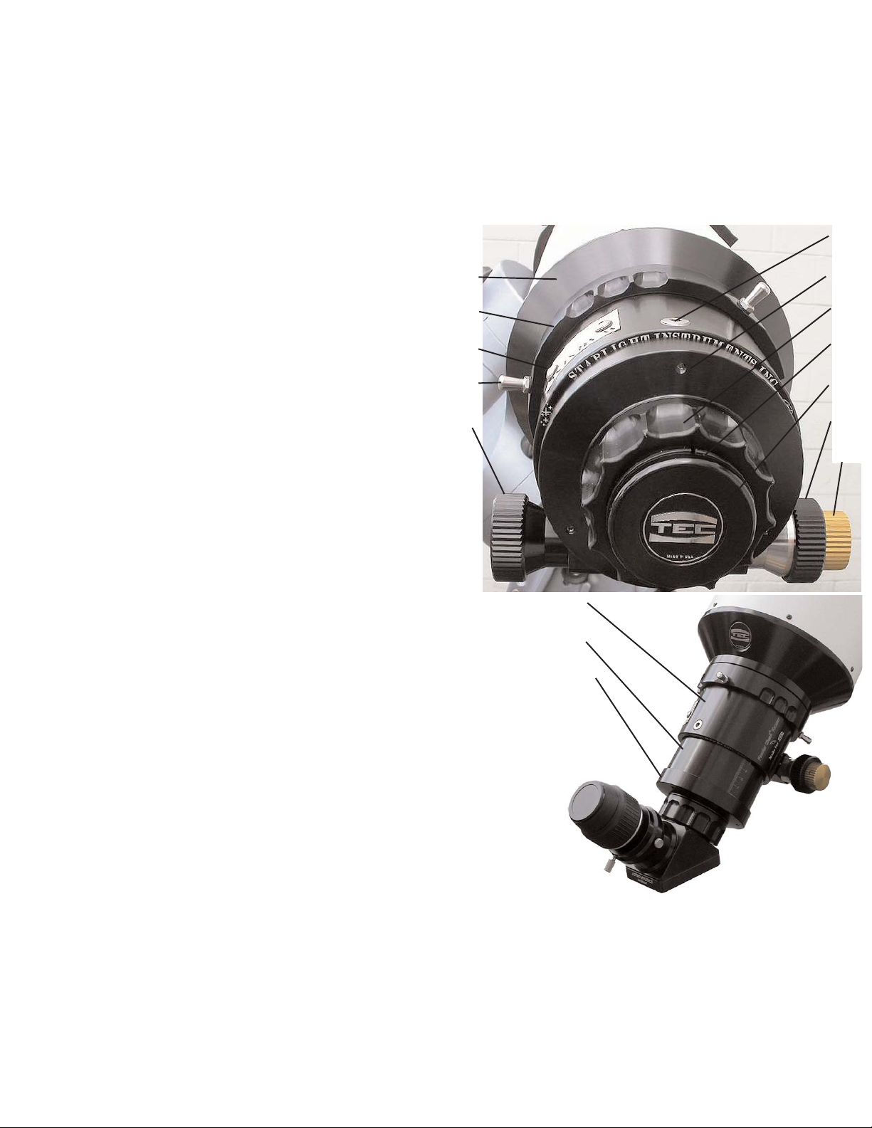
Part Description
6.1 OTA Focuser Mounting Flange
6.2 Focuser Locking Collar
6.3 Locking Collar Stems
6.4 Tension Adjustment Screw
6.5 Finder Base Screw Holes (Plugged
with (2), 8-32 Button Head Screws)
6.6 Focuser Housing
6.7 Coarse Focus Knobs
6.8 Fine Focus Knob
6.9 Draw Tube with mm scale
6.10 Draw Tube End Cap
6.11 Draw Tube End Cap Locking Screws
6.12 Eyepiece Collet Locking Nut
6.13 Eyepiece Collet Sleeve
6.14 Plug with TEC logo
Description of Design Features
1. The Feather Touch 3545 achieves excellent focusing capability
using a 9:1 Planetary Reduction Assembly coupled to a fine focus
knob (fig. 6.8). The fine focus knob should be used once the image
is close to focus and final tweaking is required.
2. The two coarse focusing knobs (fig. 6.7) on each side of the
focuser allow quick rough positioning of the eyepiece or imaging
equipment. They are coupled to the rack and pinion set and the fine
focus knob.
3. The assembly incorporating the focusing knobs, the pinion and
it’s housing is called the pinion assembly (not shown). This assembly is attached to the focuser housing using (2) 6-32 socket head cap
screws. The position of the pinion assembly relative to the rack, is
precisely adjusted by Starlight Instruments using 4 flat bottom set screws (internal to the pinion assembly) to
provide the minimum amount of backlash between the rack and the pinion for ease of operation. The other
adjustment that is made is to align the pinion axis to be parallel to the rack face.
NOTE: It is possible to reverse the pinion assembly for left handed preference but Starlight Instruments does not recommend the user reversing this assembly because of possible misalignment resulting
in a loss of performance or possible damage.
Please contact Starlight Instruments or TEC if this change is desired.
6.1
6.2
6.5
6.3
6.7
3
6.4
6.11
6.12
6.13
6.14
6.7
6.8
6.6
6.9
6.10
Page 5

4
4. The Feather Touch 3545 focuser is assembled to the OTA via the Focuser Mounting Flange (fig. 6.1), and
the Focuser Locking Collar (fig. 6.2). Loosening the focuser Locking Collar allows the focuser to be rotated to
any position relative to the telescope for ease of use. Once the focuser has been positioned, it can be locked by
turning the Locking Collar by either grabbing the grooves on this collar or by grabbing the optional Locking
Stems and rotating the Locking Collar clockwise until it is tight. The Locking Stems (6.3) help to provide a
better grip for tightening the collar. They can however be replaced with the 10-32 Button Head Cap Screws
for a cleaner look if that is desired.
NOTE: The focuser can be removed by loosening the Locking Collar and unscrewing it completely and then
pulling the focuser from the Adapter Flange. This should only be done in rare circumstances and after contacting Starlight Instruments or TEC because of possible damage that may result.
5. The drag between the Focuser Housing (fig. 6.6) and the Draw Tube (fig. 6.9) can be adjusted by using
two adjustment methods. The Tension Adjustment Screw can be adjusted using a 3/16 inch Allen wrench.
Only a slight amount of rotation on this screw makes a notable difference. Tightening this screw will allow
larger loads to be lifted without the focuser moving from the dead weight that may be attached to it and it will
also decrease the amount of deflection during positional changes during long exposures. Generally the factory
settings should be sufficient for most applications.
In addition, adjustment can be done in a simpler way - by tightening a thumb screw (not shown in the picture,
but easy to find) under the pinion assembly).
6. In the event that different equipment such as: an optional Field Flattener or AP 2.7" threaded End Cap
(available from Starlight Instruments) is needed at the end of the focuser, the Draw Tube End Cap (fig. 6.10)
can be removed by loosening the (3) 6-32 socket head set screw (6.11) and then unscrewing the back.
7. The 2 inch Eyepiece Holder does not use traditional thumb screws. This focuser uses an Eyepiece Collet
Locking Nut (fig. 6.12) and an Eyepiece Collet Sleeve (6.13). This design assures that the eyepiece or imaging
equipment is always precisely positioned and held into place during imaging. To secure your eyepiece, insert
the eyepiece into the 2 inch opening making sure that the nut has been turned counter clock wise to open the
collet sleeve and push in the eyepiece. Tighten the Collet Nut clockwise until it is tight.
WARNING: Failure to tighten the Collet Nut can result in personal injury and/or damage to equipment. Always make sure that the eyepiece is secured properly during use.
WARNING: Never point the scope to the sun without proper filtering or without the Front Cover in
place. Failure to do so can result in personal injury or damage to the collet locking sleeve and/or optics.
The Collet Sleeve is plastic and can melt if it gets too hot. Possible fumes during melting can cause fogging or damage to the optics.
8. If a finder base is to be attached to the focuser housing make sure that the screws being used are the proper
length.
WARNING: If they are too long they will contact the draw tube thereby causing damage to the
anodized surface of the draw tube.
WARRANTY
Starlight Instruments Incorporated guarantees this product to be free of any defects in material or workmanship for 3 years to the original owner. Disassembly of focuser outside of the described items voids all warranties.
Starlight Instruments Inc. • P.O. Box 68282, Schaumburg, IL 60168-0282. USA.
Phone: 847-985-9595.
Page 6
5
TELESCOPE CASE
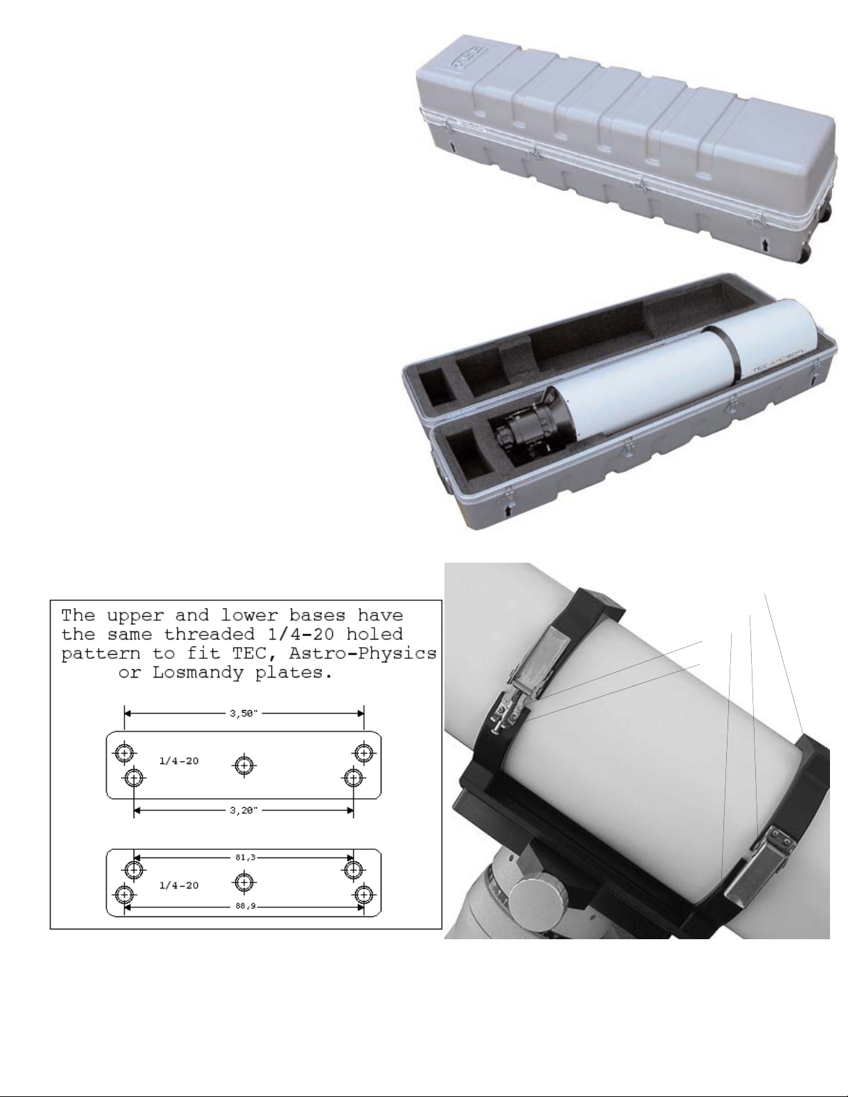
Each telescope APO180 comes with case made
by Thermodyne Company according to specs.
Thermadyne case is made out of plastic and has
hard foam interior with a few special sections that
allow to hold the APO180 with rings and plate attached.
There is a small cut section near the focuser end 8” X 3” X 5”
that can be used for diagonal, eyepices or other smal size accessories.
Dimensions for the case are: 54”L X 14”H X 13”W; weight 32lb.
Weight of case with telescope and rings is 70lb.The case has two spring-loaded
handles on each side and a couple of whells at the buttom section near the objective side.
Shipping weight of the above combination + double-wall carton box is appr. 80lb.
ACCESSORIES
TUBE RINGS
CNC machined, black anodized aluminum,
compact and lightweight design with stainless
steel latches (set of two rings weights only XXX g).
Ring hole pattern is shown in the sketch below.
Each ring contains:
Upper Base (1); Latch (2); and Lower Base (3).
Latches for the scopes of the third and forth run are adjustable. The screw (5) has a Phillips type head for easy
adjustment, the small nut (4) will hold screw in place
after adjustment.
Rings can be attached to the mount with either TEC Dovetail plate, AP or Losmandy plates.
NOTE:
From users feedback - it is better and more safe to keep rings on the OTA all the time if possible - this way
there is no chance of scratching the tube.
1
2
3
4
5
Page 7
6
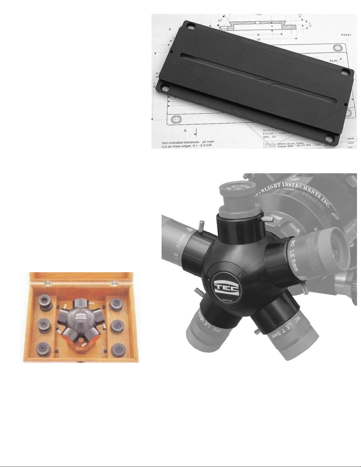
DOVETAIL PLATE
The Dovetail Plate, like all other accessories for this telescope, is CNC
machined for lightness and rigidity from
aluminum stock, and then black anodized
for a tough, corrosion-free surface.
Though having the same width and hole
pattern as Losmandy plates, the TEC
Dovetail Plate for APO180 refractors is
only 12" long and is compatible with
Losmandy, WYO or Casady Saddle systems.
Two 8-32 security screws must be
installed on each end of the Plate; these
security screws prevent the dovetail and
OTA from accidentally slipping off the
dovetail holder.
EYEPIECE TURRET
Eyepiece Turret with Mahogany case.
Precision holder for five 1.25" eyepieces.
Diagonal mirror made of Quartz.
Case safely holds six 1.25" eyepieces and ITurret. Case dimensions:
5.5" x 8.25" x 10.75"; weight - 2lb.
This new component will let you change your
favourite eyepieces very fast - just click from
one to the next one and enjoy observing.
8-32 threaded holes for security screws
CLEANING :
The tube assembly and front baffle are powder coated, to clean them use water with a soap or mineral spirits
(paint thinner); do not use Acetone or other strong chemicals. Please contact us if you need the lens to be
cleaned.
Latest updates for this manual or new accessories are available on our web:
www.telescopengineering.com and on the TEC-scopes users group:
http://groups.yahoo.com/group/tec-scopes.
Page 8
7
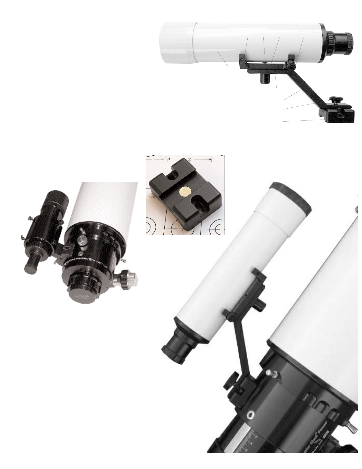
TEC FINDERSCOPE BRACKET
The TEC Finderscope Bracket is designed
to hold a traditional 50mm optical finder or
a Red Dot sight.
This new design requires only 2 thumb
screws for alignment. It looks and works in
WARNING:
IF THE SCREWS ARE TOO LONG,
THEY WILL CONTACT THE
DRAW TUBE AND DAMAGE ITS
ANODIZED SURFACE !
Shown in the above picture is the
Astro-Physics Finder bracket with finder. This combination is less expensive
and does not require an insert installation.
The Red Dot sights could also be
installed. This installation requires
fewer parts: only a Finder Base and a
Finder Arm with knob.
4
3
2
1
8 7 6 5
9
a much more elegant way. The Finderscope Bracket contains the following parts: Finder Base (1), that attaches to the focuser with two
8-32 screws; Holding Knob (2), tightening this knob will hold the
Finder Arm (3) with Finder Holder (4) to the Finder Base. The
Finder (9) is spring-loaded with spring and screw covered by Spring
Cover (6).The Finder holder has two 10-32 set screws (8) on the
objective side and two 10-32 Alignment Thumb Screws (5). A special insert (7) must be installed in the finder’s body. TEC performs this installation for free in any brands. Please note that finder’diameter should not be
larger than 2”. When attaching the finder base to the focuser housing make
sure to use screws of the proper length.
Finder base
Page 9
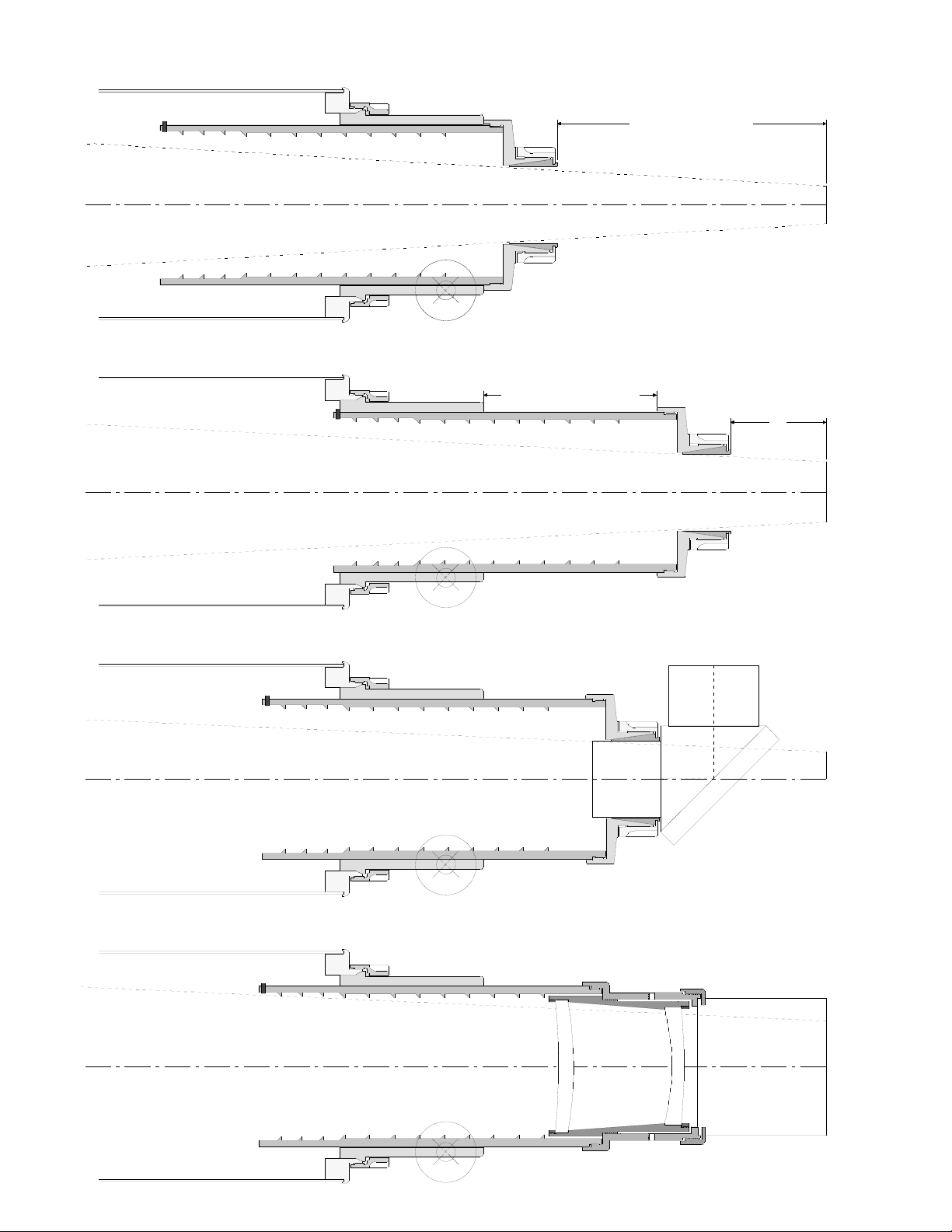
110.
7,0" BACK FOCUS
Focusing tube is completely "IN"
Unvignetted field dia. ~1.0"
Focusing tube is completely "OUT"
Unvignetted field dia. ~1.6"
3" long extension tube is required
for straight through viewing
4,5" FOCUS TRAVEL
With the 2" diagonal focusing tube is in the middle position
Unvignetted field dia. ~1.4"
camera depth 85.0mm
With the Field Flattener focusing tube is in the middle position
Unvignetted field dia. ~2.4"
2,5"
FOCUSING DIAGRAM
8
 Loading...