

Page 1
TBS Mojito Revision 2025-02-08
1
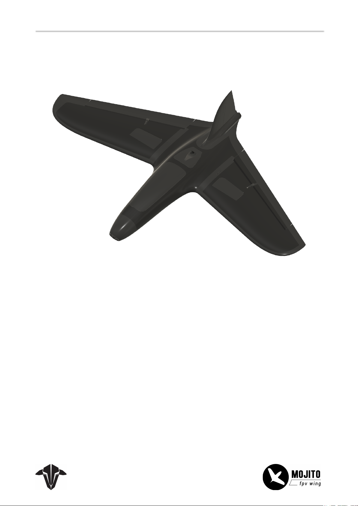
Forward-swept highly efficient long range FPV Wing
Introducing a new level of flying wing, for advanced long range FPV pilots.
Highly efficient, up to 8S capable, with very long flying times and efficiency rivalling expensive carbon fiber
models. Constructed with FPV in mind and all necessary provisions for the most popular FPV gear.
The model is a complex mixture of plastic injection and foam injection molded parts to maximize efficiency
and allow for mass-production, which makes the model easy to build and affordable to repair.
Page 2

Table of content
2
General
FAQ
Additional 3D printable Parts
INAV Tune
Kit content
Required tools:
General Installation and Information
Connect and detach the Wings and Vertical Stabilizer
Compartments and how to access them
Center of Gravity - CG
Installation
Wing PCB with FC
Servos and air breaks
Motor
ESC - Installation
ESC - Setup
Receiver
Wing Connectors
FPV Gear
LED Strips
Detailed Installation (DIY Kit)
Main Body
Wings
Vertical stabilizer
Additional Information
Elevon Tuning
air break Setup
Page 3

General
3
FAQ
If you have any questions after reading this manual, visit the TBS FAQ section.
Additional 3D printable Parts
If you want to customize your MOJITO wing, several 3D printable parts are available.
From a WING PCB holder to custom nose sections and extra antenna outlets.
INAV Tune
You can find an INAV 7 preset on GitHub.
Page 4
Kit content
4
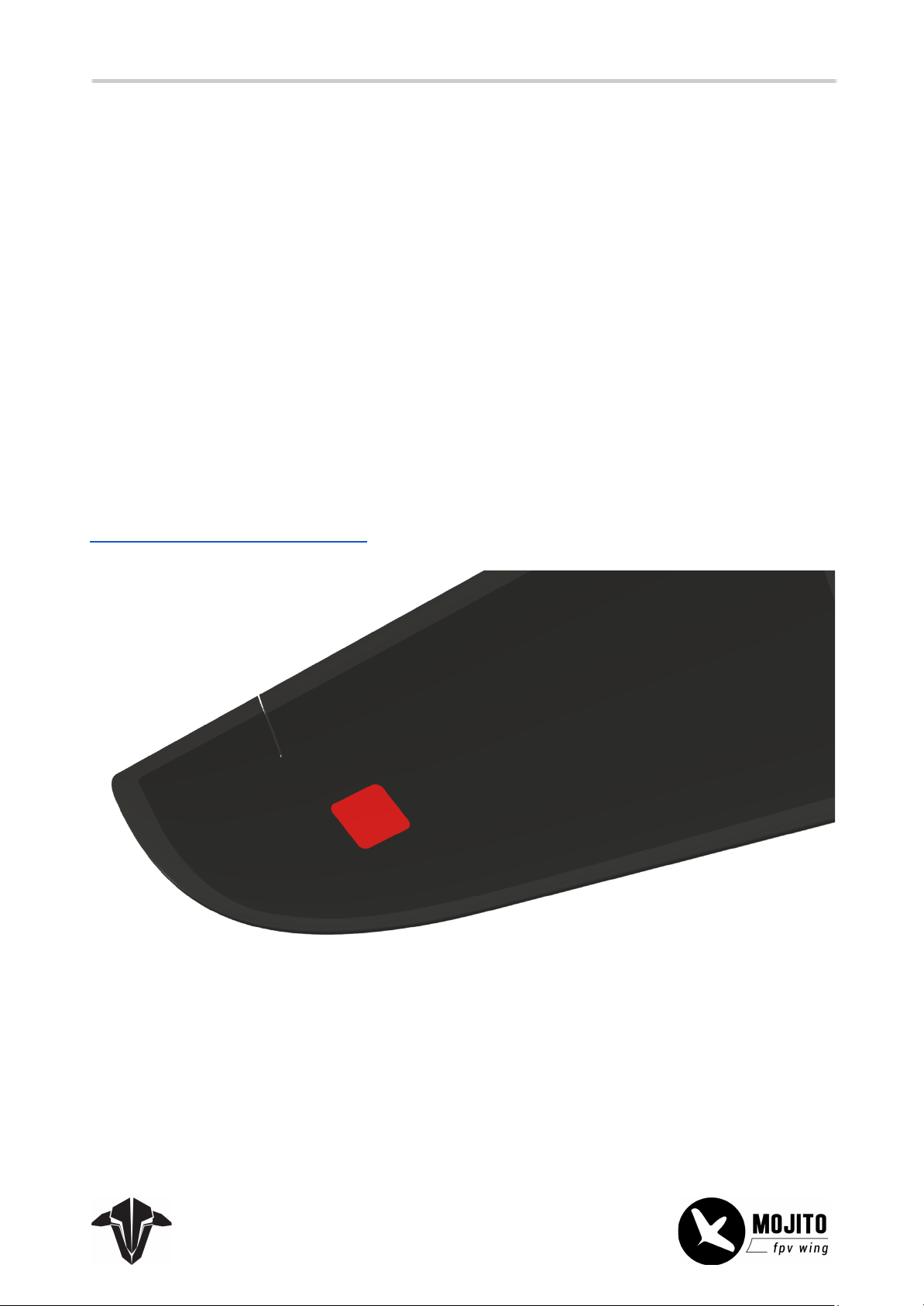
Both sets, the DIY and the KIT version, come without electronics. We recommend the following parts, some
of which are packed as an “Electronics Package”:
- TBS LUCID F4 FC (or F7 if later available)
- TBS LUCID 3-12S Single ESC
- TBS LUCID WING PCB
- TBS MOJITO Motor (1000KV, 3220)
- TBS MOJITO Servos (2x minimum, 4x if you want to use the air breaks) (23mm wide)
- USB Adapter Cable, 90° connector (for easy FC access), available at TBs
- 8S >1800mAh, 6S >2600mAh Battery
- 8x4.5 or 7x12 Prop
Important note:
Advanced pilots may wish to install electronics in the wing tips. To do that, you need to order the
DIY version. Otherwise, you will not be able to feed any cable there!
Check the installation section for details.
Required tools:
- EPP-safe glue like UHU POOR or CA glue like Multiply Zacki
- Exacto knife (optional)
- Filament tape (about 1m) and double-sided tape (optional)
- Drill bit + respiratory protection (DIY only, to cut a slot in 2 carbon beams if needed, optional)
Page 5
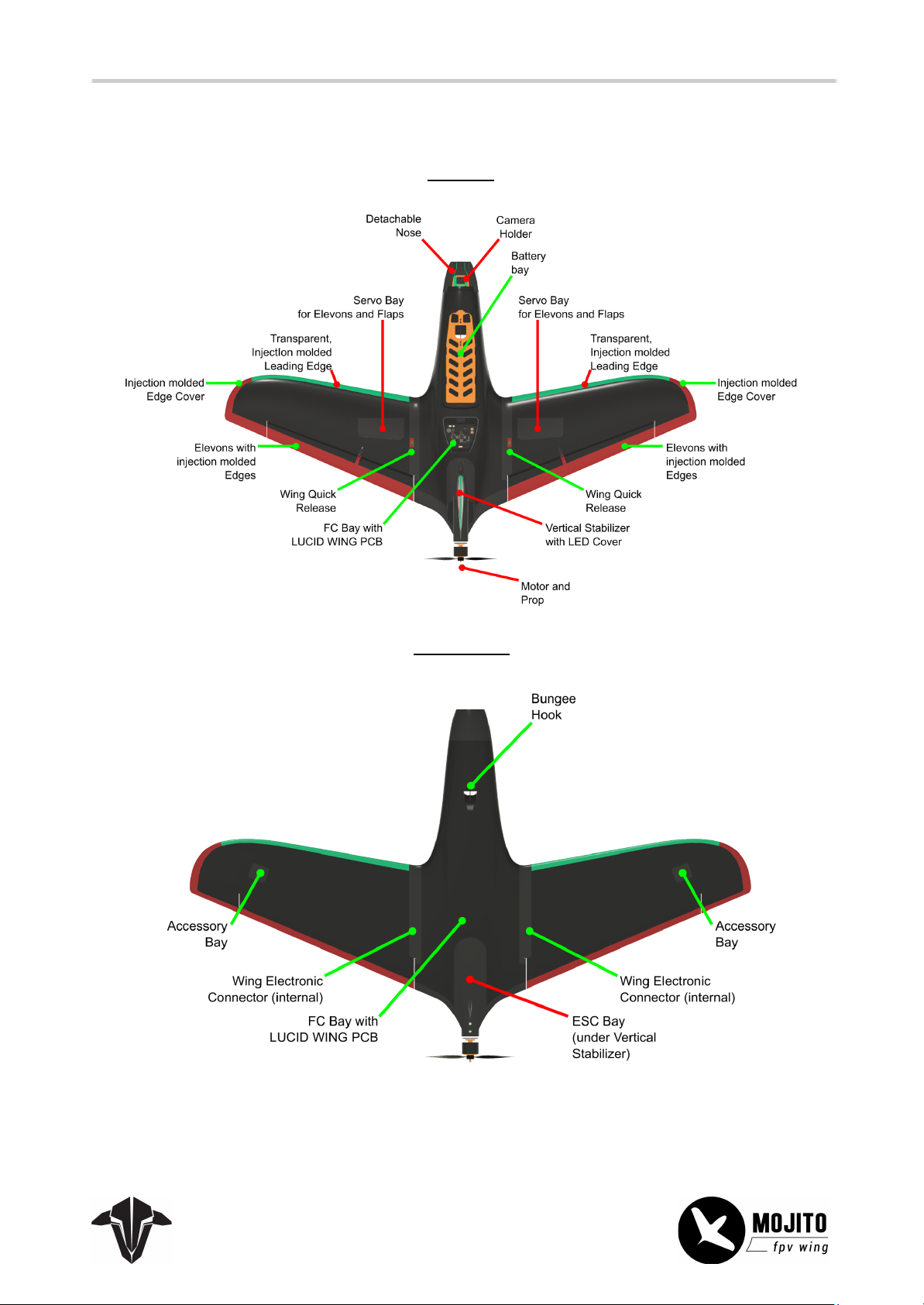
Overview
5
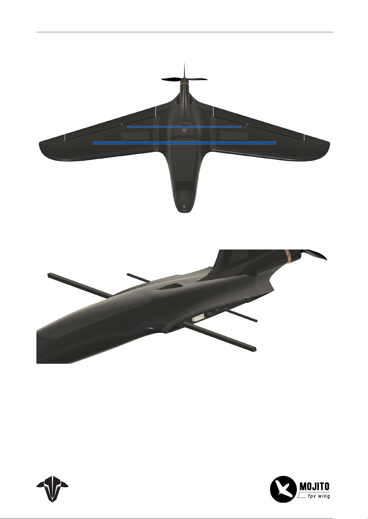
Top View
Bottom View
Page 6
General Installation and Information
6
If you are experienced with building wings and just need the base information or are finished with the
general assembly and gluing, this section is for you.
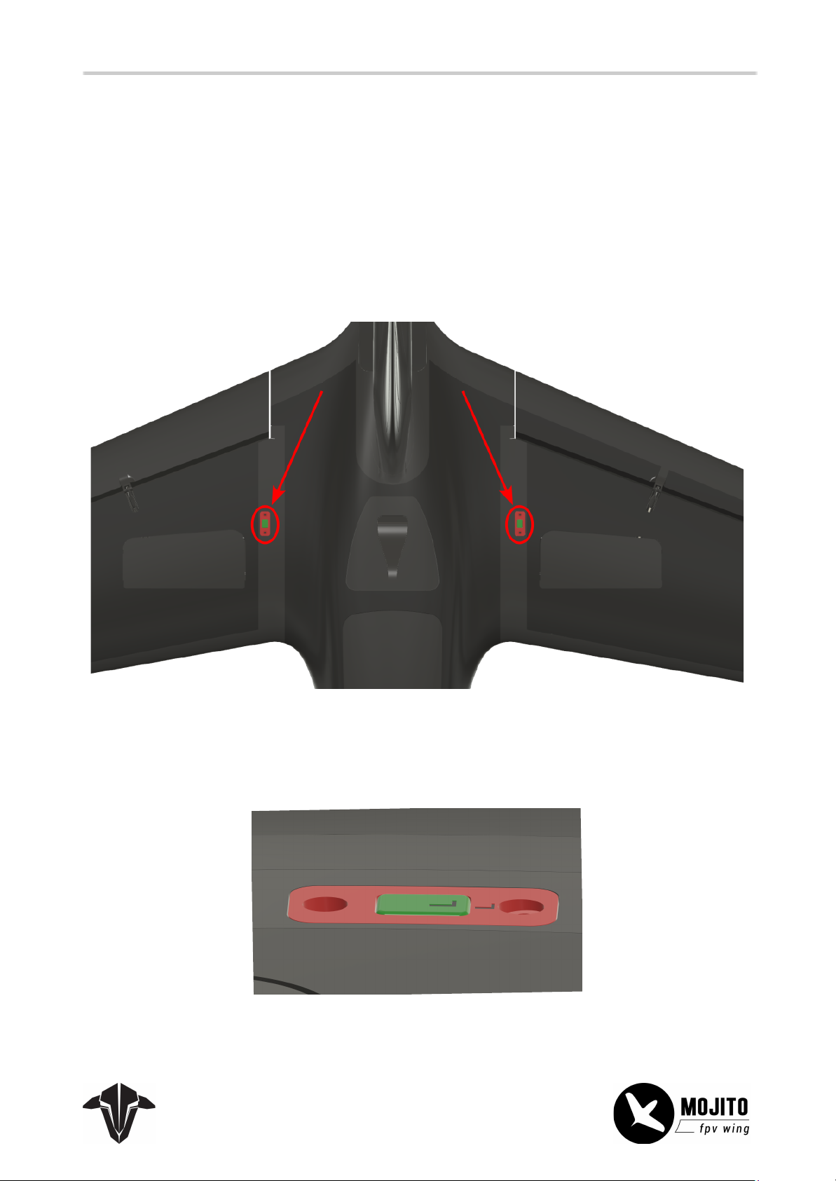
Connect and detach the Wings and Vertical Stabilizer
To detach the wings, you need to push the quick-release buttons down. If you can't press them in deep
enough, you can use a pencil, screwdriver, etc., to force them deeper until you hear a “pop” sound and the
wings come off easily. Do not pull them with force!
Connecting them is as easy as detaching them. Install the two carbon rods into the main body and slide
the wings on them till the end. When done correctly, the push button will be flush.
Page 7
When your wing is brand new, you might need to push it a little harder for the button to pop out.
7
Two carbon rods reinforce the wings inside. Install them by sliding them into the designated guides.
Page 8
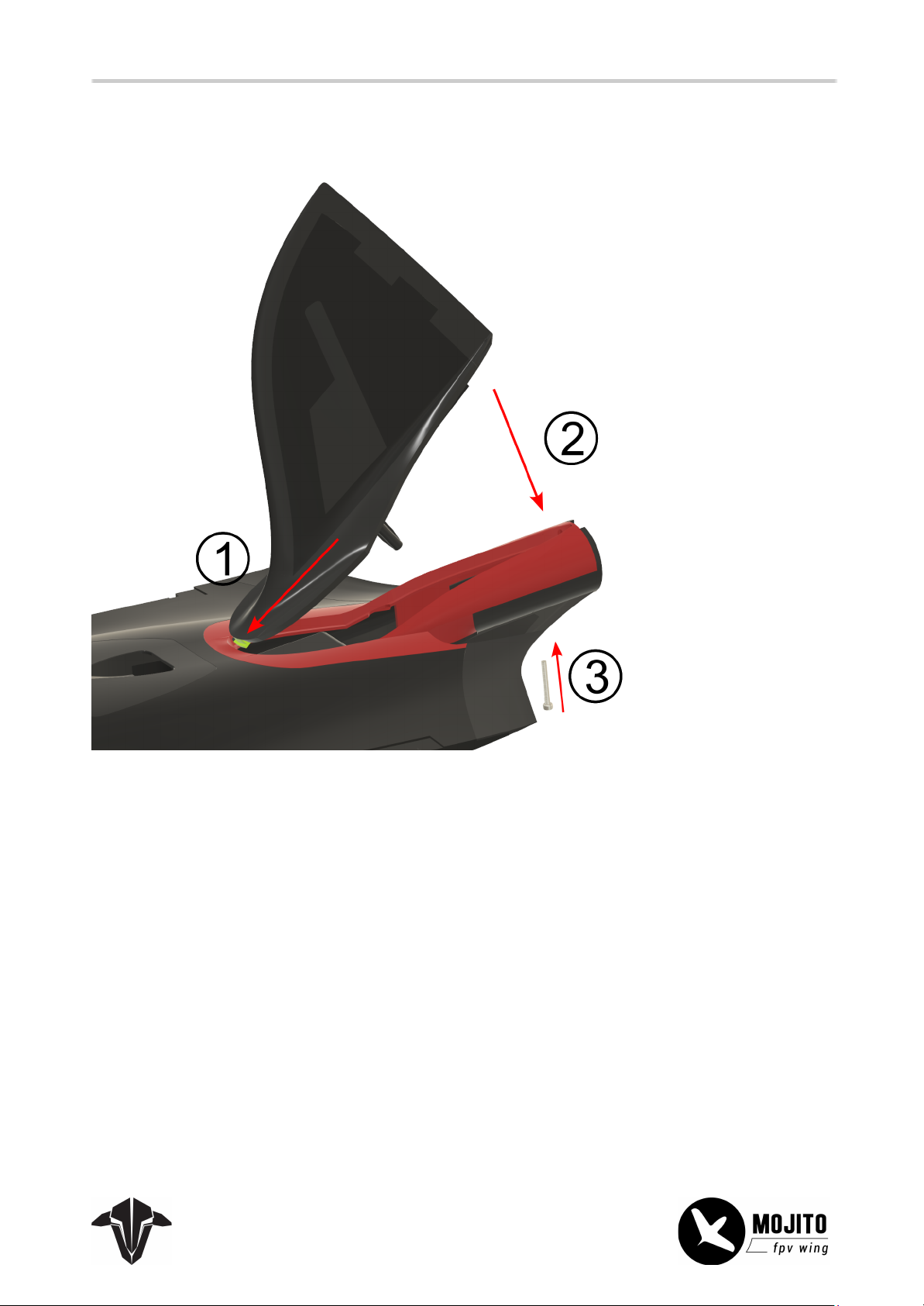
The stabilizer must be first pushed in at its front, then pushed down. To lock it in place, the screw must be
8
installed as well.
Page 9
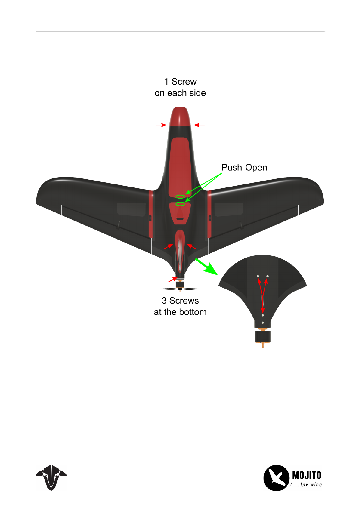
Compartments and how to access them
9
Page 10
10
Center of Gravity - CG
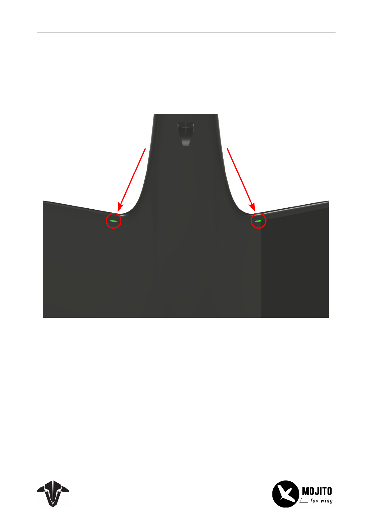
You can feel a protruding line at the bottom about 1cm from the wing's leading edge. This line marks the
CG. Place your fingertips on them, and make sure your MOJITO is leveled. If you want to do proximity
flights, your plane should be slightly nose-heavy for better control in those scenarios.
Installation
Install the FPV gear, the receiver, and other electronics as far apart as possible to avoid interference. Try
moving the unit away if you experience issues with your RC or video link.
Page 11
Wing PCB with FC
11
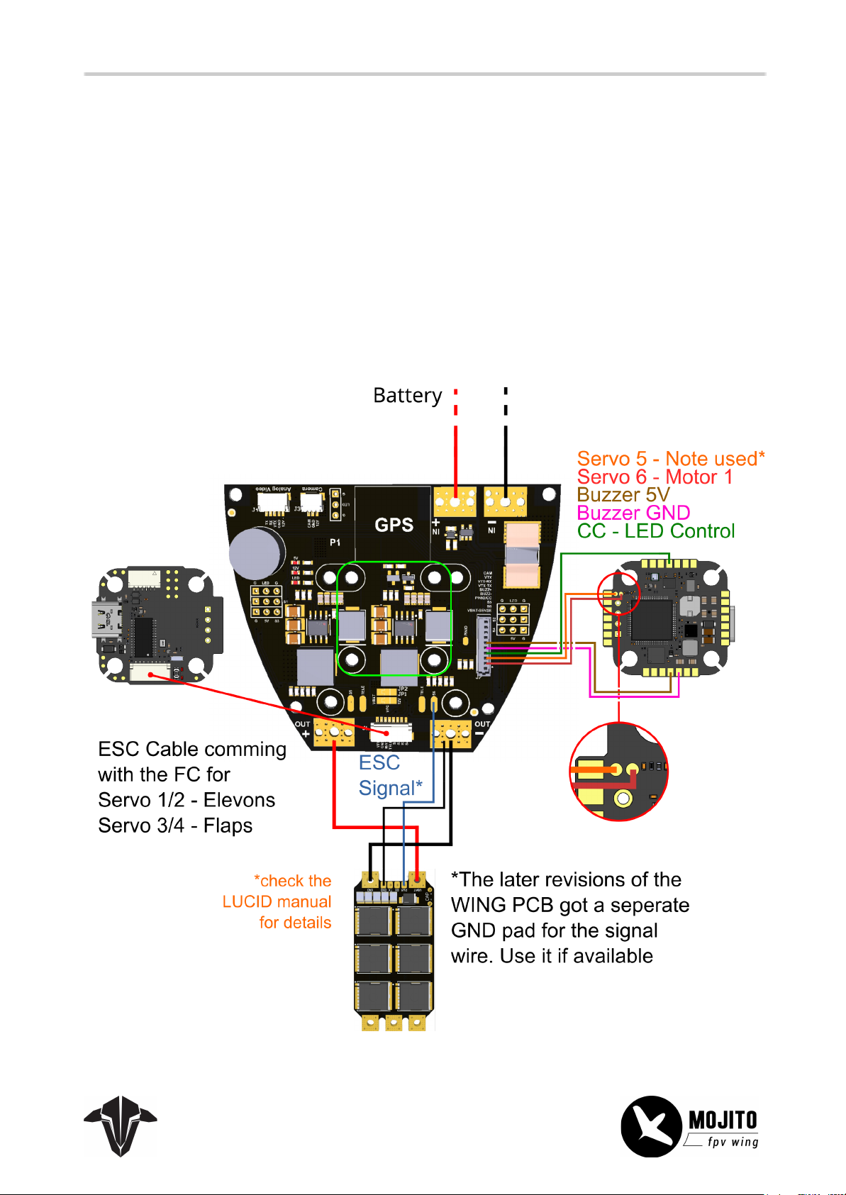
The Wing kit contains a dedicated PDB that mounts the FC and all the necessary gear cleanly and easily,
providing clean power and minimizing the wiring. Installation can be done with some double-sided tape or
a 3D-printed adapter. If you use a digital FPV system, connect your VTX to a free UART. In the case of an
analog system, connect the WING PCB
dedicated pads as well.
You can connect your Lucid FC directly up to 8S
It is also recommended that some foam be placed over the barometer to avoid false readings when air
passes by in flight.
CAM, VTX, VTX RX (if supported by the VTX), and VTX TX
to the
Page 12
Servos and Air Breaks
12
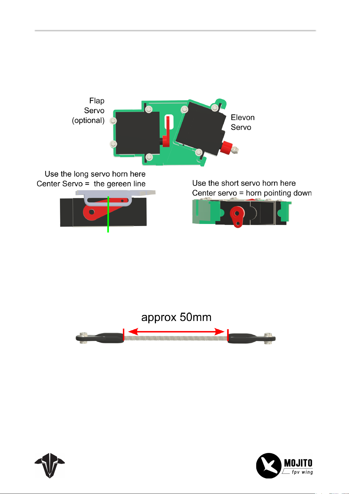
The Servos are held by the included flat-head screws. No additional glue is needed.
The air break hinge is held by the same type of screw that is holding the servo.
Make sure to adjust the servo limits in your FC software. They should move to their endpoint without
stressing sounds or pushing into the foam. The air break must be flat with the wing surface when not
engaged.
The push rod should be adjusted so that when the servo is centered, the elevon is in one line with the
surrounding edges. This can be achieved by turning the hinges. A spacing of 50 mm is a good starting
point.
Page 13
Do not use any Locktide on plastic parts!
13
Motor
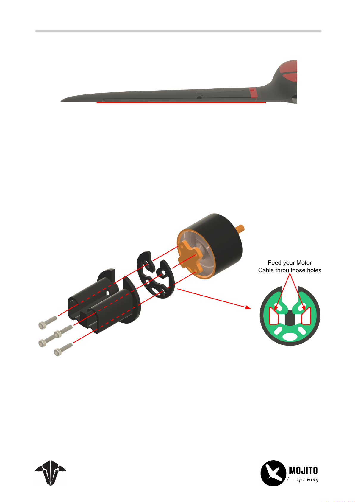
The mount supports Motor bases from 19*19 up to 25*25mm.
Install the Motor with the 4 M3x9 socket head screws. Make sure to install the spacer, as otherwise, the
screws can penetrate the motor windings!
Gently bend the motor cables so they fit into the designated holes.
Page 14
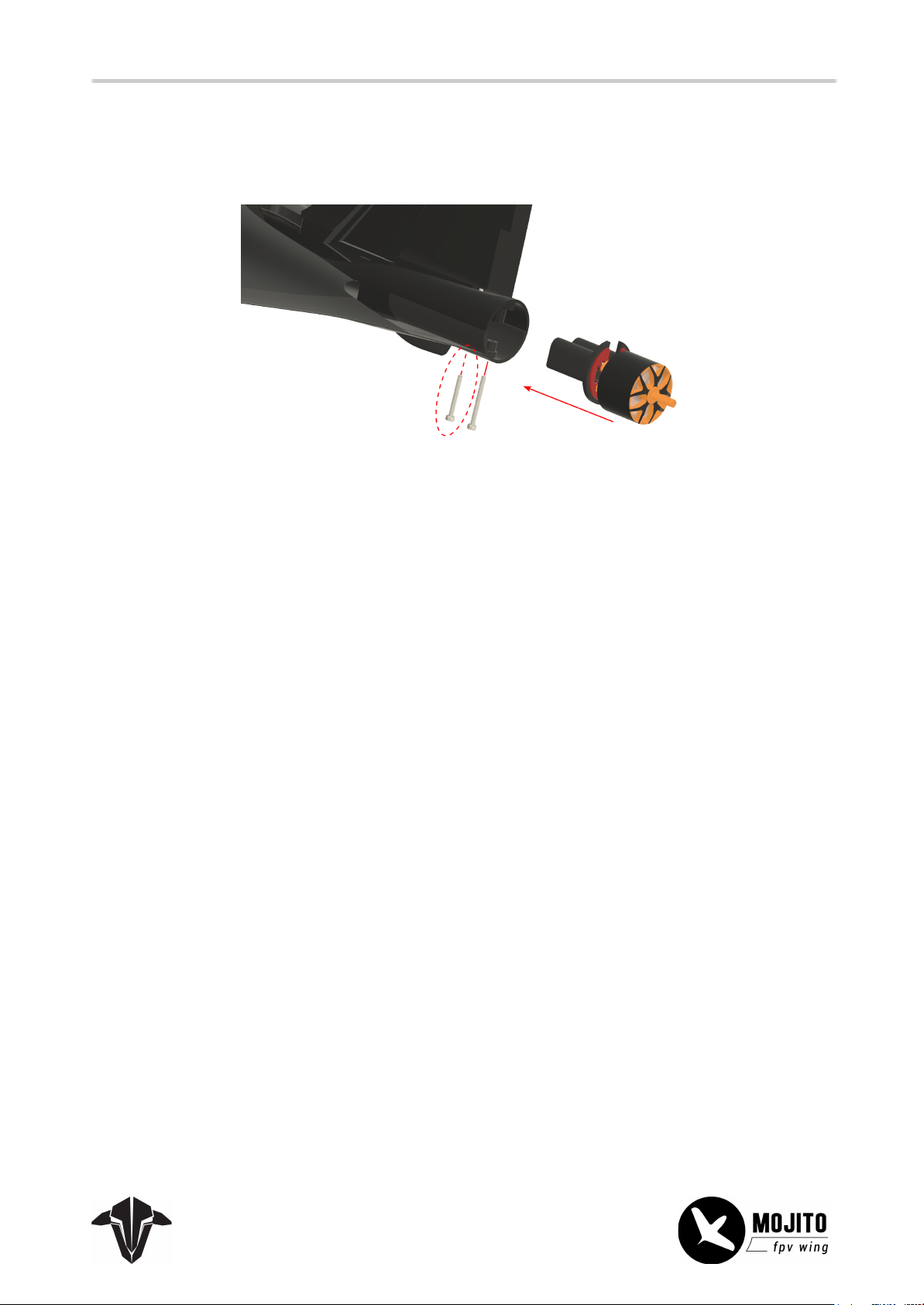
After assembling the mount, install the motor and its mount on the wing. The circled screw goes through
14
the motor mount as well while mainly holding the vertical stabilizer. Make sure it can pass through the
mount after tightening the main screw.
Page 15
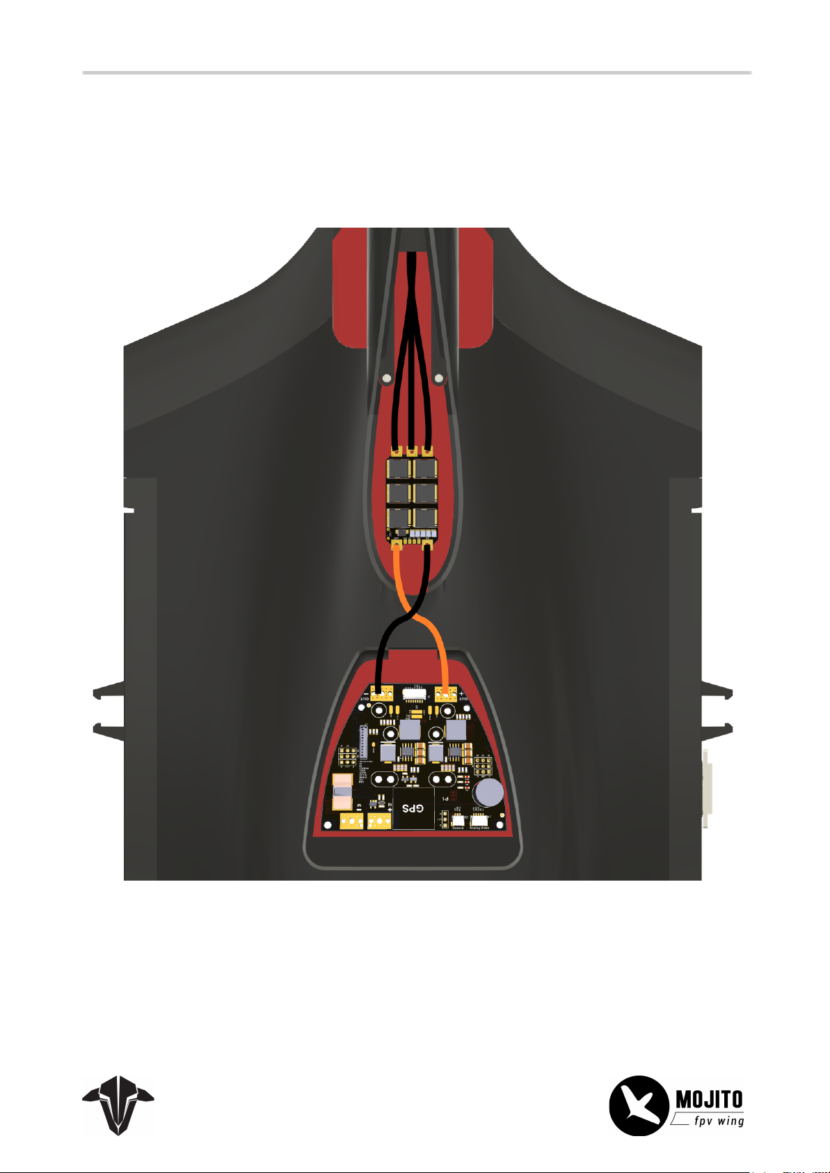
ESC - Installation
15
The ESC can be placed in the bay under the stabilizer. To improve cooling, add some of the thermal paste
to the FETs and press the supplied heat sink onto it. To secure it further, add a small stripe of heat shrink
tube or a zip tie around it. Make sure not to over-tighten it.
Page 16
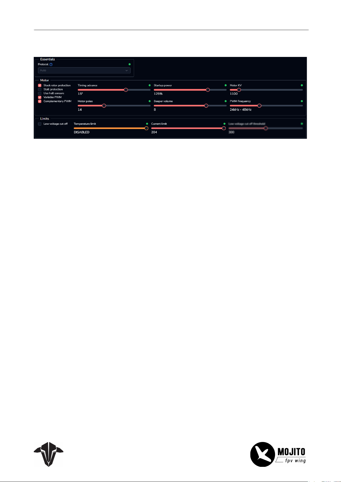
ESC - Setup
16
Stuck Rotor Protection: ON Startup power: 125%
Stall Protection: OFF Motor KV: 1000
Use Hall Sensor: OFF Motor Poles: 14
Variable PWM: ON Beeper Volume: 8
Complementary PWM: ON PWM Frequency: 24-48KHz
Timing advance: 15° Temperature Limit: OFF
Current Limit: 204 Low voltage cutoff: OFF
Break on Stop: On Running Brake Level: 10
Page 17
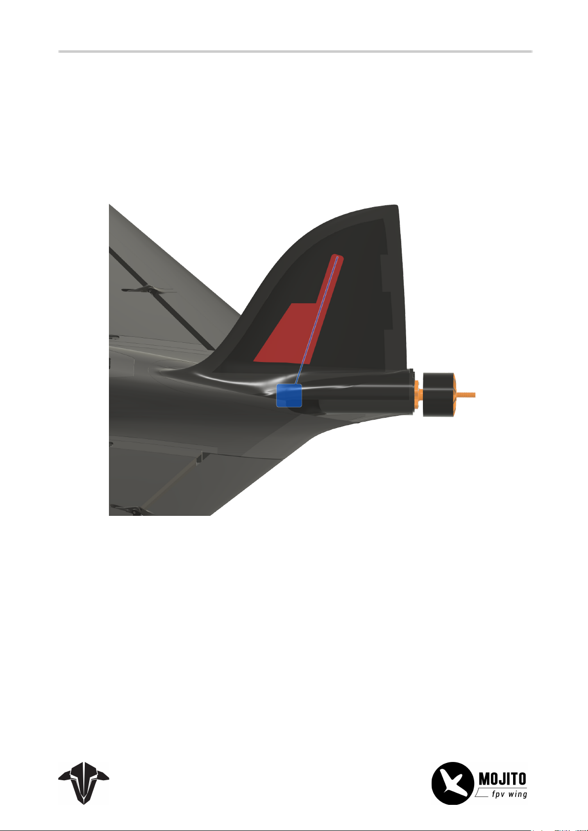
Receiver
17
The receiver can be installed on the flight controller. The
antenna can be placed inside the special compartment inside the vertical stabilizer.
Alternatively, you can install the receiver into the bay and feed a Cable with a (4 pin) servo connector to the
FC to easily remove the stabilizer with the receiver for transportation.
Crossfire Immortal T Antenna V2 Extra Extended
Wing Connectors
Both wings include a 12-pin connector, allowing for easy disassembling without the need to fiddle around
with servo connectors.
Page 18
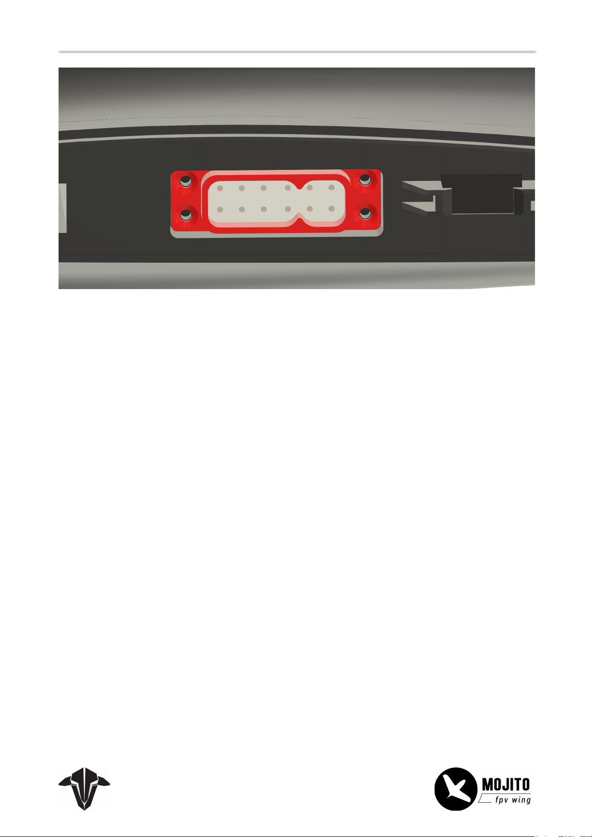
You can use the pins as you like. If you want to use the LED stripes in the wing edge and a VTX, you might
18
need to use some pins for multiple devices. For example, using the same pin for 5V and GND for both
servos allows for VTX (with CRSF) and LED, and both servos by just using 12 pins.
Page 19
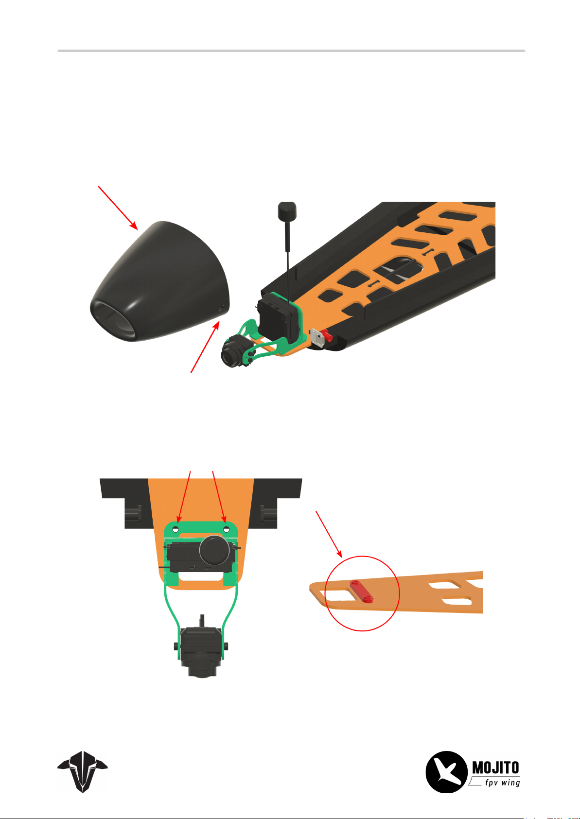
FPV Gear
19
The nose section can easily be removed by removing the two M3x2 socket head screws on the side and
then pulling it out to the front. When tightening the screws, do not apply too much force to them, as they
just need to hold the cover and are installed into foam.
For the antennas, just poke a small hole through the foam of the main body, about 1-2cm in.
The VTX/ camera holder itself is held by two m3x8 self-attacking socked head screws installed through the
wooden base and into the small bracket.
Page 20
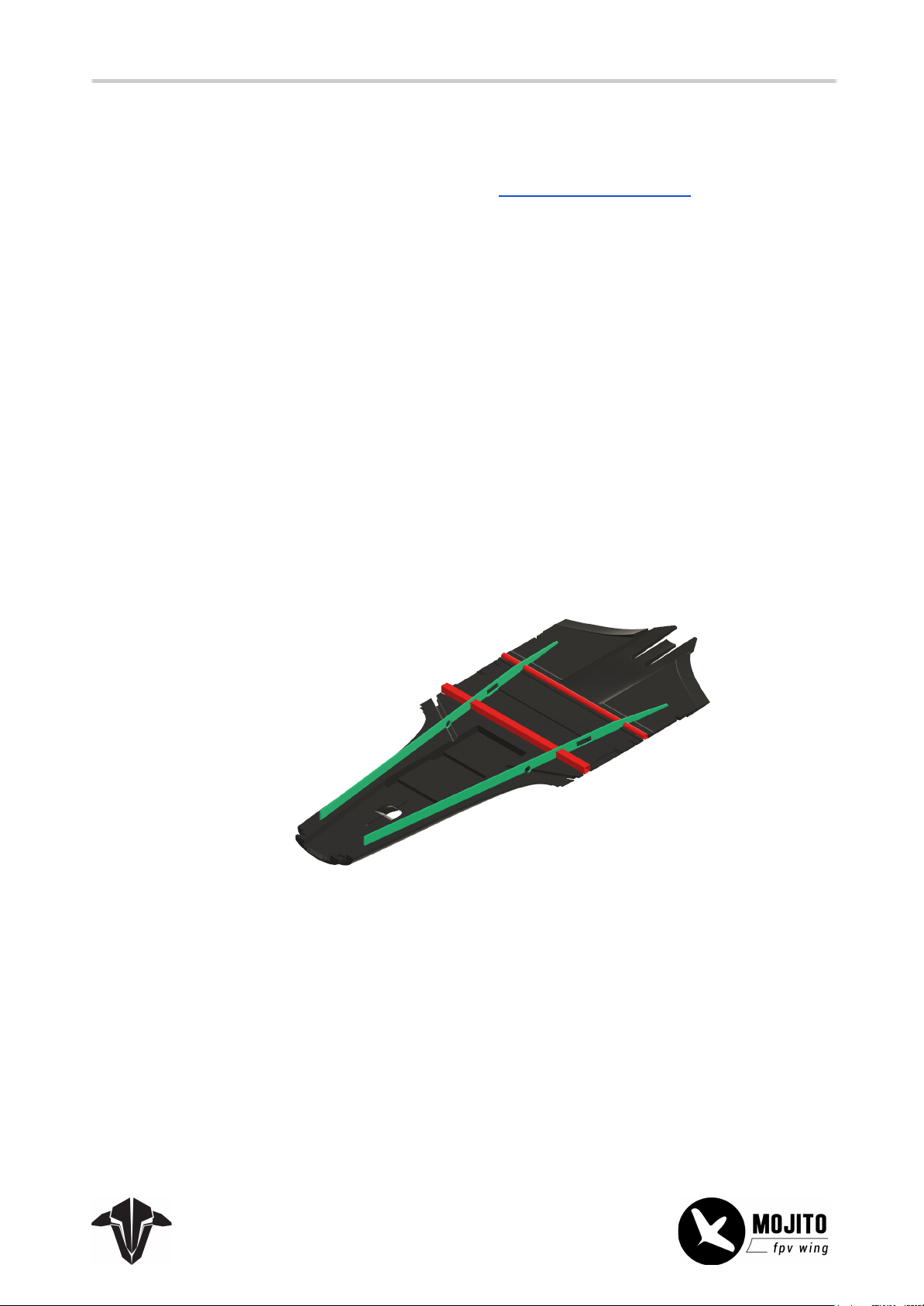
20
LED Strips
The details for installing the LED strips can be found in the assembly part for the wings.
For the control, enable the PINIO function for an available pin (CC - Pin on the LUCID F4) and route the
function to a free channel on your FC.
Detailed Installation (DIY Kit)
Main Body
The main body installation is an easy process, just take your time and make sure to remove excess glue
from any parts to avoid issues. Running a dry fit first is also a good idea to see how parts align before
applying the glue.
Start by installing the main carbon ribbons and the two (shorter) carbon tubes. Push them down firmly
and make sure that the tubes are centered.
Page 21
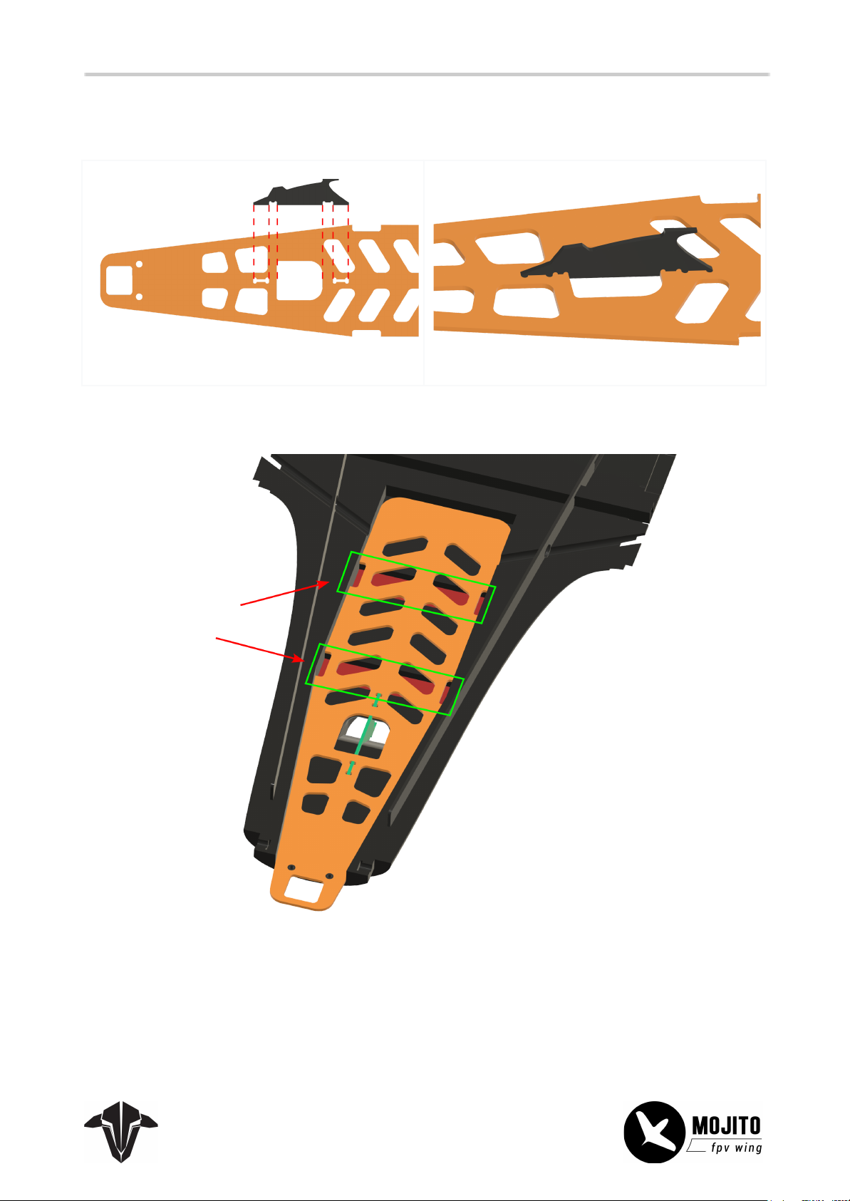
Next is the battery bay base plate with the velcro straps and the bungee hook.
21
First, install the bungee hook into the plate and secure it with CA glue.
Then, wrap the velcro straps around the base plate and glue the base plate in place. Avoid glue in the
pockets for the velcro strap - that way, it can be replaced later if necessary.
Page 22
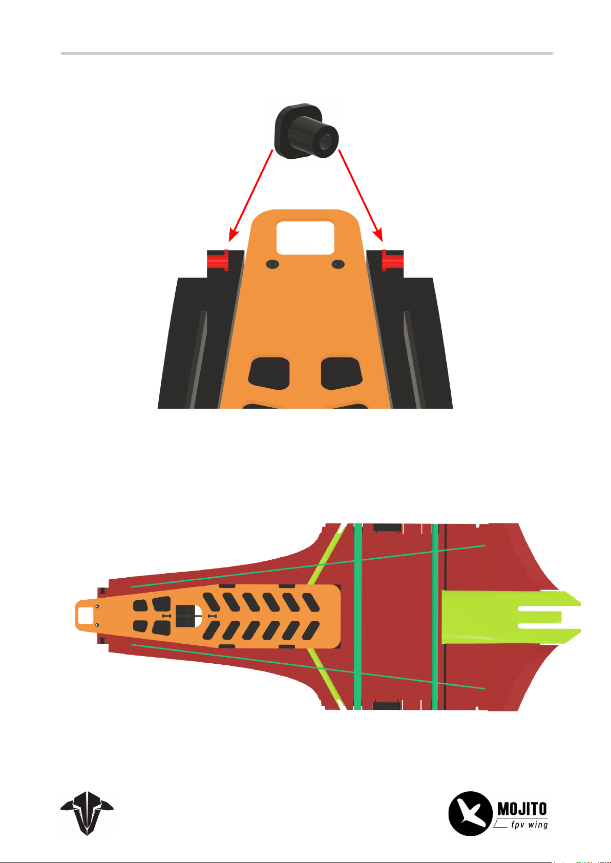
The last step on the bottom is to install the clips for the nose.
22
Add glue to the complete surface (red areas) and the carbon parts (green parts) when all parts are
installed. The yellow areas must remain free!
Now press the top half of the main boy onto it and secure it with painter's tape.
Page 23
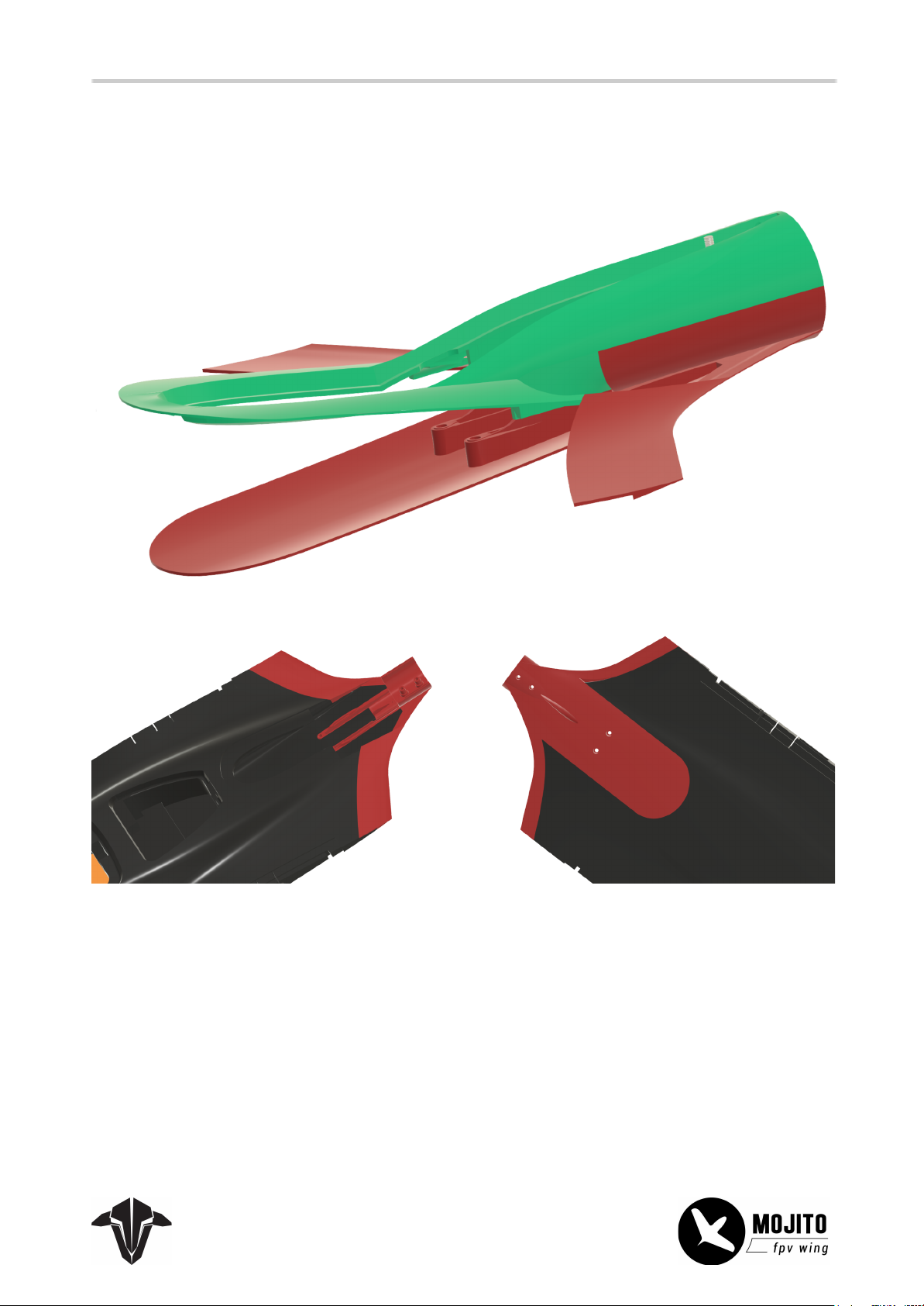
Next, the motor mount/ESC bay must be glued in place. When pushing it onto the foam, ensure it is flush
23
against it and no gaps are visible. The two halves must fit properly after they are in place. You can clip
together and insert the screw(s) in the back to ensure they are positioned correctly.
Page 24
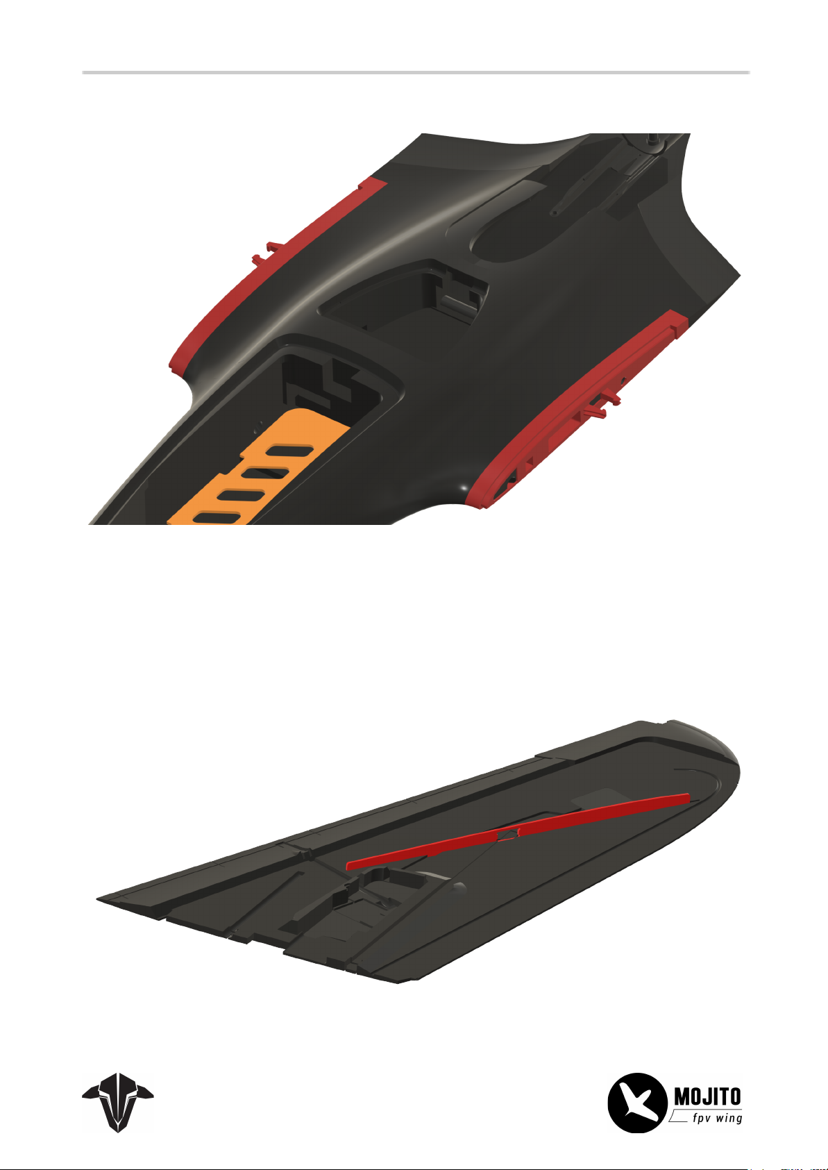
After that, the wing connectors are installed in the same manner.
24
Wings
Start by installing the main rod.
Page 25
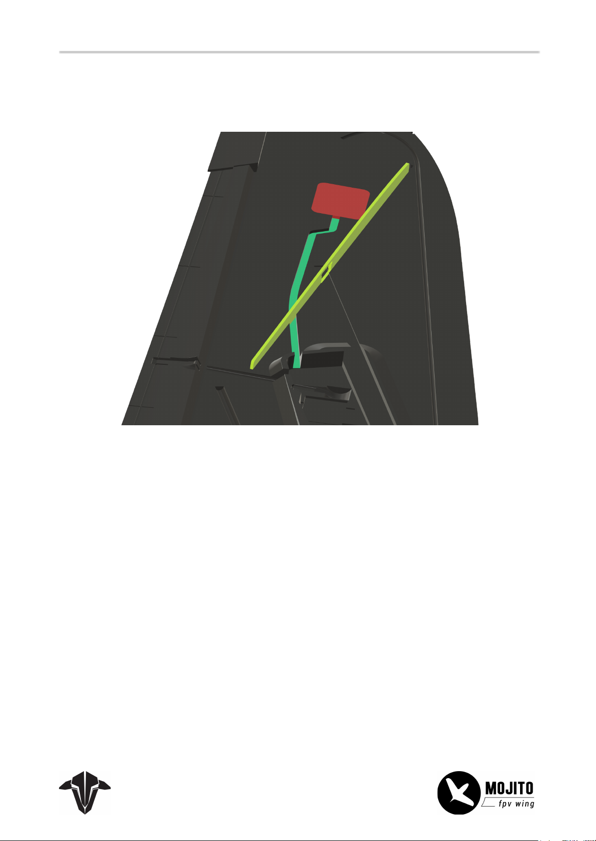
Important Note:
25
If you plan on using the compartment in the wing area, you must drill a hole into the carbon. Otherwise,
the channel (green) for the cable will be blocked and can no longer be opened!
Next, install the servo bay plastic tray, and screw down the servos.
Page 26
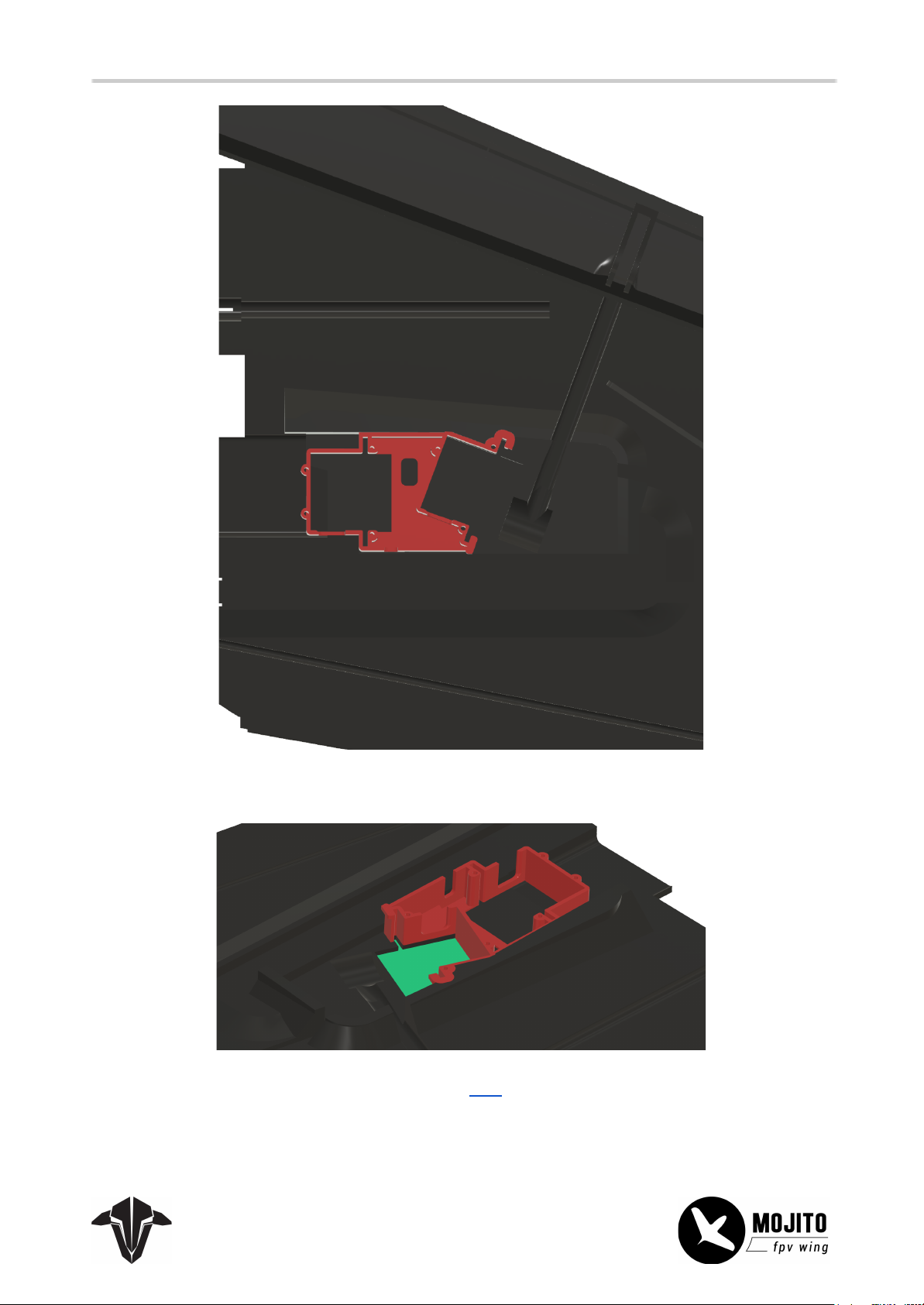
Make sure the surface of the servos (green) is free of glue!
26
Details on how to adjust the servo horns can be found here.
Page 27
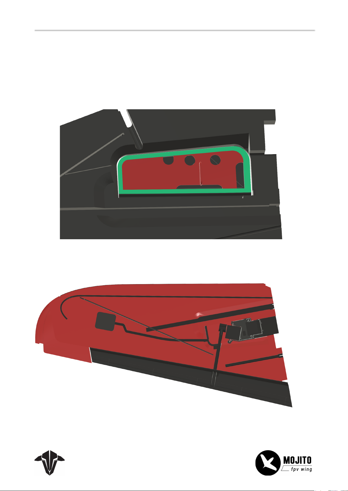
27
If you plan on using the air breaks, now is a good time to install the plate for them. The plate (red) fits
perfectly into the top wing half's raised borders (green). If you want to, you can install it later as well.
If you don’t (yet) want to use the air breaks, cover the top surface of the air break with some tape to
ensure a flat surface.
Add glue to the wing half (red areas) and push the top part of the wing on it.
Page 28
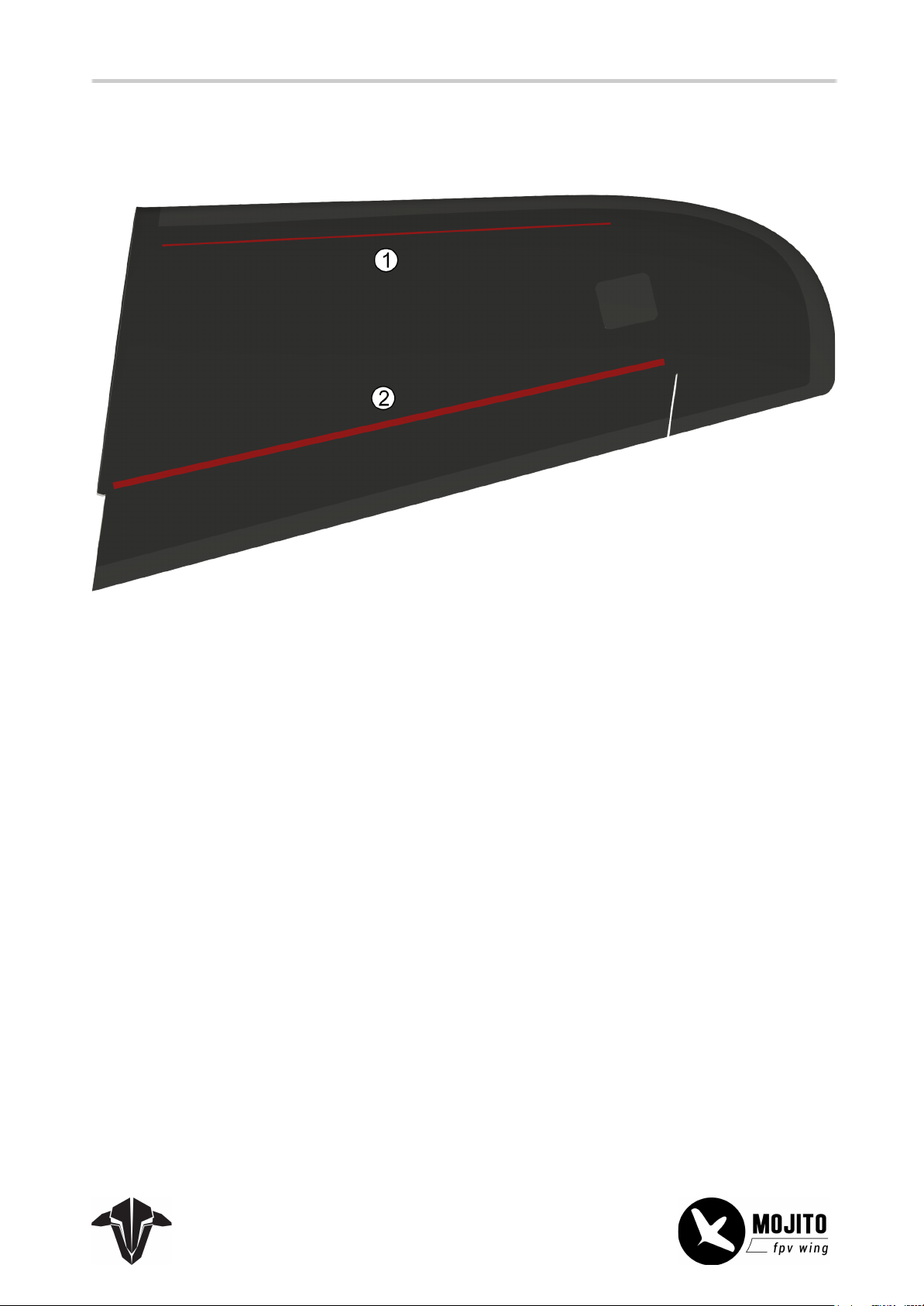
At the bottom of the wing are two more spares (1-small, 2-square tube). glue into the two slots and spread
28
it with a piece of paper or the spare itself
You need to run a wire from the edge to the wing connector to install the LED strips on the leading edge.
Create a shallow cut for the cable (recommended), or simply press-fit it under the plastic wing connector
and feed it into the servo bay to connect it to the electronic connector.
Page 29
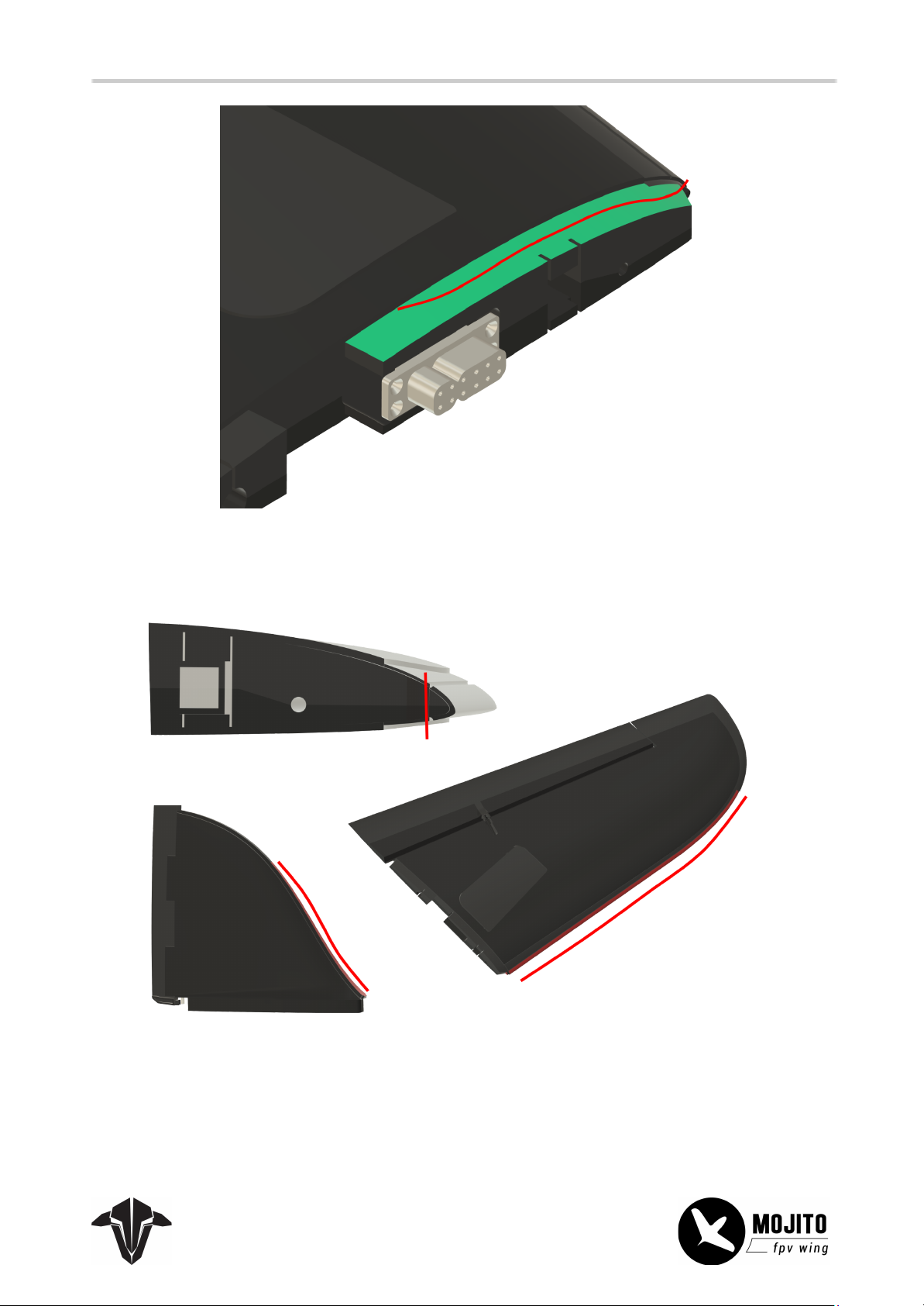
29
For the installation of the LED strip itself, cut the round edge at the notch along the wing front. On the
vertical stabilizer, the surface is already flat. Glue your LED strip on the flat surfaces.
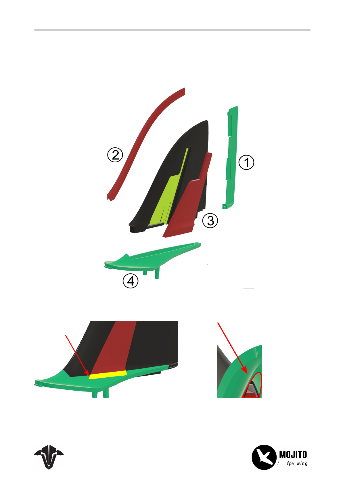
Next, install all the plastic parts in the shown order.
Page 30
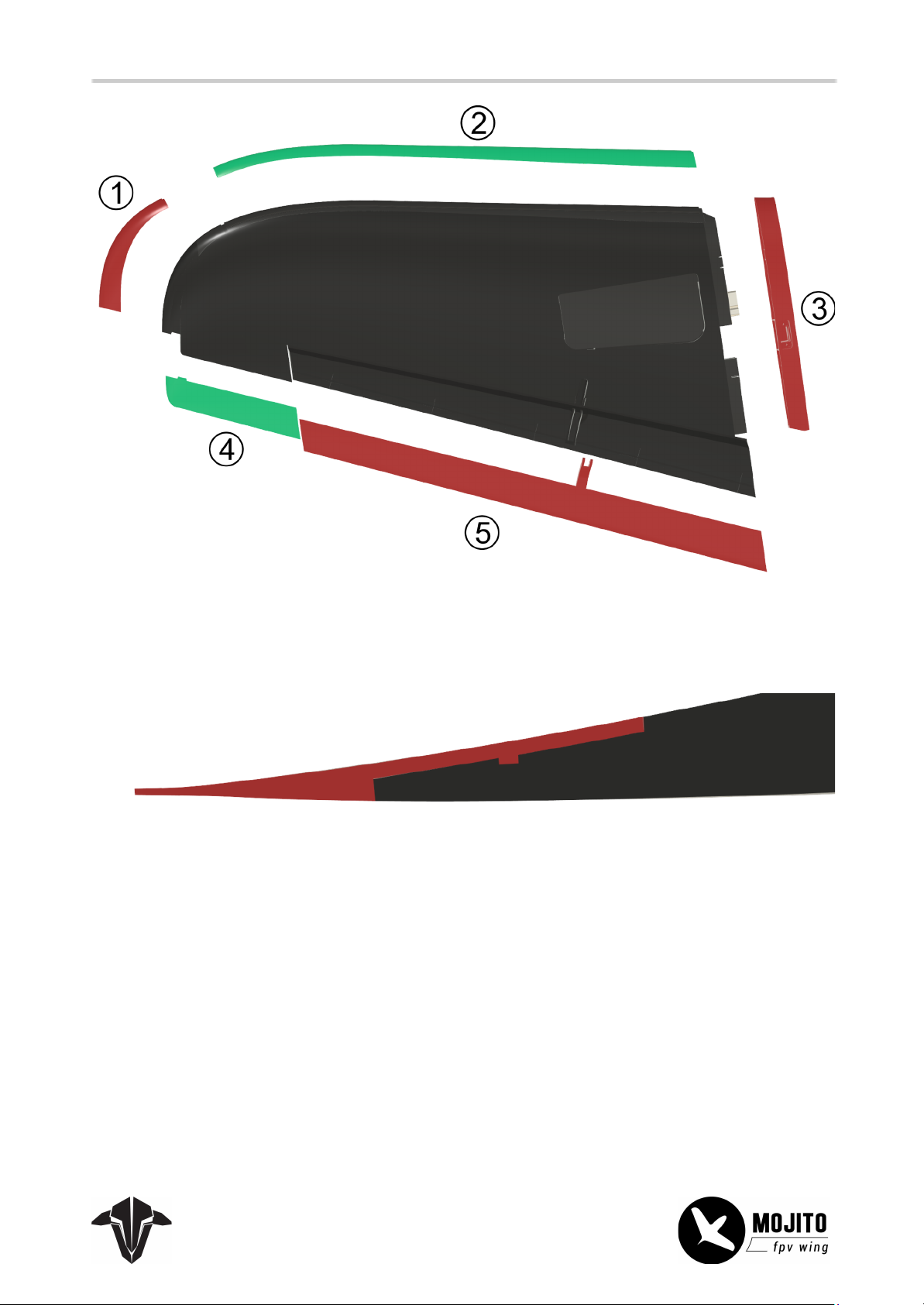
30
On the Elevons, make sure the notches align and that you use glue on the whole contact surface.
Page 31
Vertical stabilizer
31
Install the plastic parts of the vertical stabilizer in the shown order.
When just gluing the bottom of the antenna bay cover (3) and then covered by some clear tape or just
slightly glued in on the rest, the cover can be removed to change the antenna or later installation.
Page 32
Additional Information
32
Elevon Tuning
To get your elevons to respond more crisply, you can modify them.
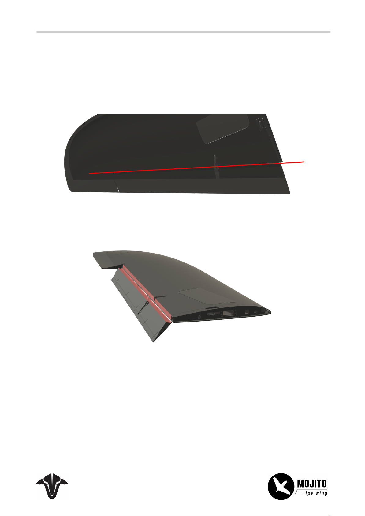
Remove the push rod and cut the factory hinge along the red line.
Install some double-sided tape on both surfaces. The tape must be as wide as half of the final filament
tape. Then, add the filament tape over it while moving the elevon down close to 90° and press it firmly.
Page 33
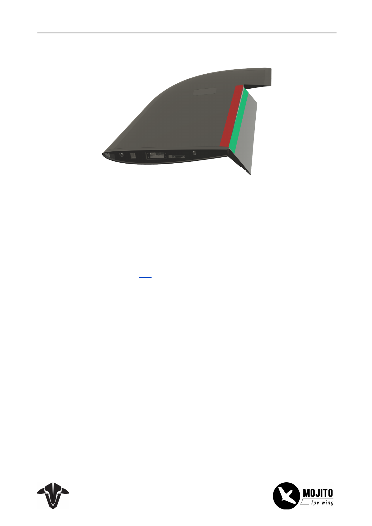
Next, repeat the steps on the other side while moving the elevon up as far as possible.
33
When down, the elevon should move without resistance. Reconnect the servo link and check the servo
throw and center.
Air break Setup
The air breaks are useful if you want to lower your airspeed, e.g., while landing or doing some proximity
flying. If you plan on using them as a “hand-break”, the servo speed should be high, for a more controlled
engagement, about 1.5-2 seconds is a good starting point.
The installation details can be found here.
Important note:
When engaged, the air breaks causing the plane to dip its nose. If you use a flight controller with a
stabilized flight mode, it will be compensated. Otherwise, you should program a pitch compensation into
your radio model.
 Loading...