

Page 1
Page 2
2
:: Introduction
Thank you for purchasing this Team Associated product. This assembly manual contains instructions and tips for building and maintaining your new RC10TC6.2.
Please take a moment to read through this manual to help familiarize yourself with these steps.
We are continually changing and improving our designs; therefore, actual parts may appear slightly different than in the illustrations. New parts will be noted on
supplementary sheets located in the appropriate parts bags. Check each bag for these sheets before you start to build.
:: KIT Features
Team Associated is proud to release the next step in its developmental line of 1:10th scale 4WD electric touring car kits, the RC10TC6.2-FT, further refining the
already successful TC6 platform.
The touring car racing class has been moving forward at an aggressive rate, and the Engineers behind the doors of Area-51 have been hard at work evolving
the TC6 platform to keep the pace. The RC10TC6.2-FT car kit comes equipped with a host of new features to allow for more precise suspension adjustment and
consistent handling for any track condition.
With over two year’s development on the TC6 chassis, the TC6.2-FT car kit ties together all the experience and Factory Team race tested parts. Focusing on precise
suspension adjustments with features such as the new independent arm mount system with interchangeable toe inserts and pivot ball joints. A new dual
bellcrank steering system has optimal Ackermann and steering rates, and is controlled by a servo on a floating mount for steering to match today’s aggressive
racing conditions. Updated bulkhead and top plate configurations allow for optimized flex through the entire length of chassis to give the best grip on any surface.
The RC10TC6.2-FT packs together the key features necessary to keep you at the top of the racing circuit. All without sacrificing low part count or affordability.
It’s plain to see that the RC10TC6.2-FT kit is… another “Champion by Design” from Team Associated!
:: Key Features
• Updated arm mount system
o Pivot ball on inner hinge pin allows free pin movement at any toe
or kickup angle
o Insert system for precise adjustment of inner pin width and toe
o Independent arm mount design to allow maximum flex through
entire chassis length, resulting in better grip on all track conditions
• Dual bellcrank steering system
o Optimized Ackermann and steering rates
o Horizontal ballstuds for fine Ackermann adjustments
o 8 precision bearings for accurate swing motion
• Floating servo mount
o Servo mounts to chassis center to allow equal chassis flex in both
directions and a tweak free assembly
o Mount ties to steering bellcrank posts for stable servo positioning
o Slotted servo mount design allows fit for almost any standard servo
• Narrow chassis with optimized flex characteristics
o 2.25mm graphite laminate for optimized flex characteristics
o A narrow 88mm wide to minimize chassis dragging at maximum
chassis roll angles
o Chassis ballast mass mounting locations to fine tune mass balance
• Updated spur gear bulkheads
o Mounting pattern has been made independent of arm mount to
allow flex through entire length of chassis improving overall grip
o Narrowed mounting pattern to allow for more chassis flex and
consistent traction
o Symmetric design helps to minimize part count
• Updated motor mount & spur gear mount
o Floating spur gear design allows for more flex from rear of chassis
helping to gain traction in all conditions
o Motor mount attaches to center line of chassis with a floating post
connection to allow free chassis flex in both directions
• Updated vertical ball stud bearing caps
o Optimized position for inner ball stud
o Vertical ballstud orientation allows for fine adjustments of roll
center height
o 3 link position options give precise control of camber gain
• Spur gear lowered by 1.50mm to give more aggressive handling
characteristics
• Top plate lowered by 1.50mm to allow for more chassis flex and increased
traction in any condition
• Rear gear diff for maximum performance and minimal maintenance
o Lightweight design
o Durable composite construction
o Optimized for a wide “tuning window” to maximize useable
adjustability
o Hard anodized aluminum outdrives for low wear and long life
• Front spool with replaceable composite outdrives
o Outdrives allow the use of existing CVA bone blades to minimize
binding at the bearing surface
o Composite outdrives are replaceable at low cost in the event of a
CVA bone blade failure
• Cross-compatibility with all TC6.1 suspension components
• VCS3 Shock with hard anodized threaded shock bodies
o Bottom loading seal system for ease of build
o TiN coated shock shaft
o Piston attaches to shock shaft with screw for tight clamping and no
slop
o Threaded collar with fine pitch thread for ease of accurate ride
height adjustment
• Titanium turnbuckles with turnbuckle eyelets for easy access to ball stud for
adjustment
• 22 precision ball bearings
:: Items Needed
Your new FT TC6.2 comes unassembled and requires the following items for completion. (refer to catalog section for suggestions):
• 1:10th scale electric motor and electronic speed control • 1:10th scale 190mm lexan touring car body and Lexan specific paint for body
• 3.7V-7.4V LiPo, 6.6V LiFe, or 4.8V-7.2V NiMh/NiCd battery
• Battery charger (suited for, and particular to, one of the batteries mentioned) • Strapping tape for battery
• 2 channel surface transmitter, 2 channel receiver, and steering servo • 1:10th scale rubber (or foam) touring car tires, rims and inserts
:: Other Helpful Items
• Silicone Shock Fluid (Refer to catalog for complete listings) • Silicone Diff Fluid (Refer to catalog for complete listings) • Thread Lock (AE Part #1596)
• Body Scissors (AE Part # 1737) • Reamer / Hole Punch • FT Hex Wrenches (AE Part # 1541) • Hobby Knife
• Needle Nose Pliers • Wire Cutters • Soldering Iron • Calipers or a Precision Ruler
Associated Electrics, Inc.
26021 Commercentre Dr.
Lake Forest, CA 92630
http://www.TeamAssociated.com · http://www.RC10.com · http://twitter.com/Team_Associated · http://bit.ly/AEonFacebook
Customer Service
Tel: 949.544.7500
Fax: 949.544.7501
Page 3
1/14
:: Table of Contents
3
1...................Cover
2...................Introduction
3...................Table of Contents
4-5...............Shock Build (Bag A-AA)
5-8..............Spool and Differential Build
(Bag B-BB)
8-9.............. CVA’s and Turnbuckles Build
(Bag C-CC)
10-11.........Suspension Arms Build
(Bag D-DD)
12-16........Bulkheads, Spur Gear, and
Steering Rack Build (Bag E-EE)
16-20........Steering/Caster Blocks and
Rear HubsBuild (Bag F)
26-28.........Tuning Tips
29................Gear Chart
30-37.........Catalog
38................Notes
39................Setup Sheet “Kit Setup”
40................1:1 Hardware “Fold Out”
41.................Setup Sheet “Blank”
42................Back Cover
21-25.......Bumper, Anti Roll Bar, and
Electronics Build (Bag G-GG)
:: Notes
This symbol indicates a special
note or instruction in the manual.
!
This symbol indicates a Racers Tip.
There is a 1:1 hardware fold out page in the
back of the manual. To check the size of a part,
line up your hardare with the correct drawing
until you find the exact size. Each part in the
foldout has a number assigned to it for ordering
replacement parts.
Associated Electrics, Inc.
26021 Commercentre Dr.
Lake Forest, CA 92630
http://www.TeamAssociated.com · http://www.RC10.com · http://twitter.com/Team_Associated · http://bit.ly/AEonFacebook
Customer Service
Tel: 949.544.7500
Fax: 949.544.7501
Page 4
4
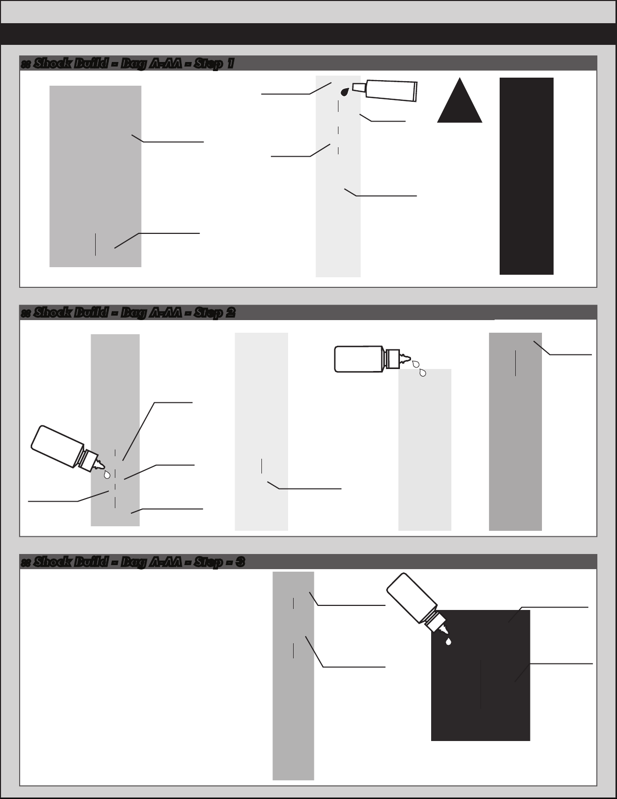
:: Shock Build - Bag A-AA - Step 1
31325
VCS3 shock
body
31327
VCS3 shock
bottom cap
o-ring
:: Shock Build - Bag A-AA - Step 2
31510
M2x4mm
bhcs
31324
VCS3
piston
bushing
#1596
thread lock
6465
Shock
piston
(#2)
31330
VCS3 shock
shaft
Shock oil
#5423
(40wt)
!
Thread lock
not included!
31324
Shock
bladder
31324
VCS3
o-ring
Shock oil
#5423
(40wt)
spacer
5407
Red
o-rings
31324
Hat
bushing
31327
VCS3 shock
bottom cap
:: Shock Build - Bag A-AA - Step - 3
Bladder Installation
With the shaft extended 25%, place bladder on
the top of the shock body, displacing the extra oil.
While maintaining pressure on the bladder against
the shock body, carefully lift one side of the bladder
to allow any extra oil to escape. Place stock cap on
top of bladder, and secure it by threading the
aluminum cap retainer onto the shock body.
31305
Turnbuckle
eyelet
31328
Aluminum
cap retainer
VCS3 shock
VCS3
31329
cap
Shock oil
#5423
(40wt)
31326
VCS3 shock
collar o-ring
31326
VCS3
shock collar
Page 5
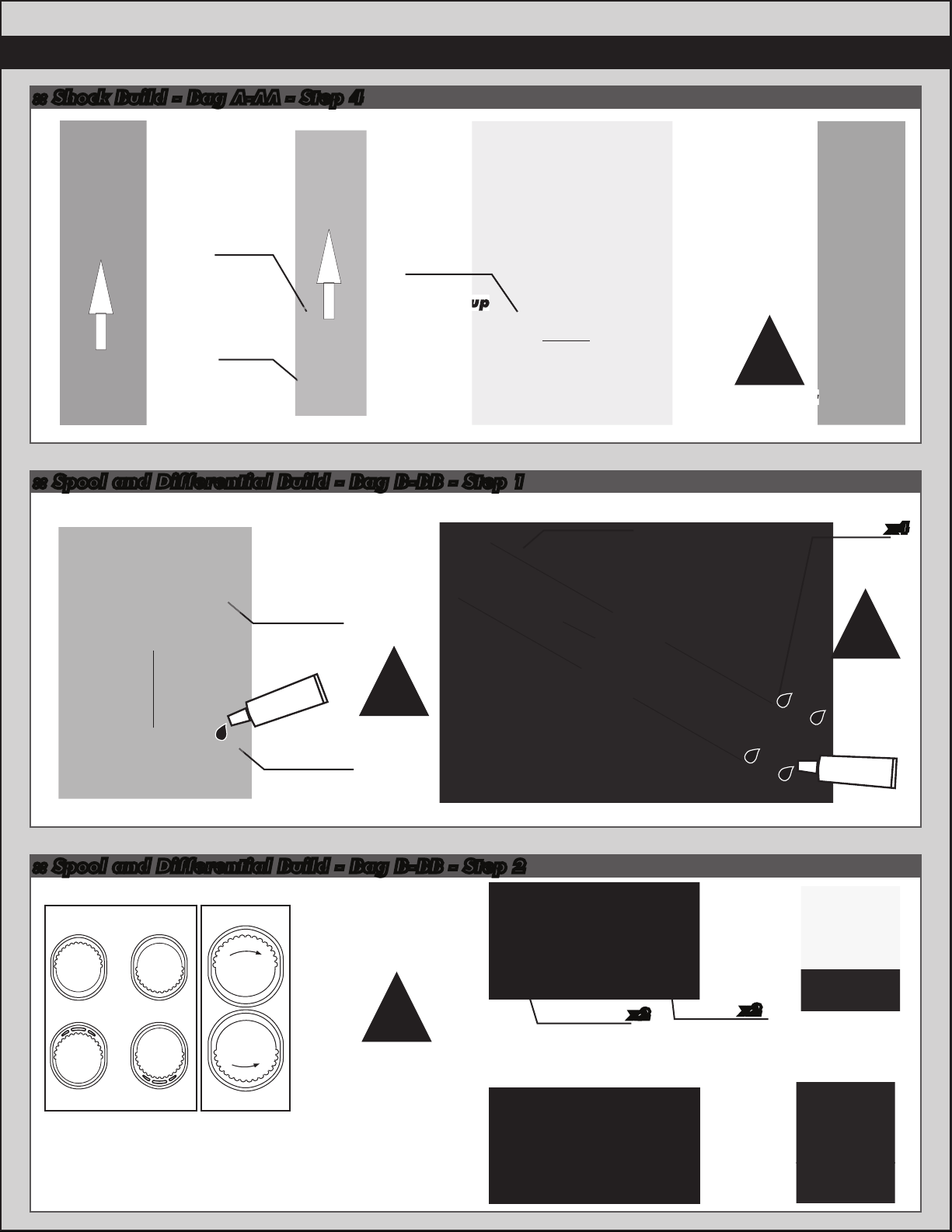
:: Shock Build - Bag A-AA - Step 4
3942
Silver
spring
14.5lb
(front)
3942
Silver
spring
14.5lb
(rear)
6475
Shock
spring cup
:: Spool and Differential Build - Bag B-BB - Step 1
5
!
Build four
shocks
31175
Diff pulley
flange
#1597
ca glue
31175
Diff pulley
(40T)
!
CA glue
not included!
:: Spool and Differential Build - Bag B-BB - Step 2
Belt Tension
Cam Position
Number
Left Side
161
31342
Spool hub
31510
M2x4mm
bhcs
!
Thread lock
not included!
#1596
thread lock
x4
Mid-Low
Low
Note!
Always use the same
cam position on both
sides of the car.
Mid-High
High
17 32
View from left
side of car
!
Use belt tension
position 8 for
standard setup.
Right Side
31615
Cam
holder
(mid-low)
x2
31615
Diff
bearing
cam
x2
Page 6
6
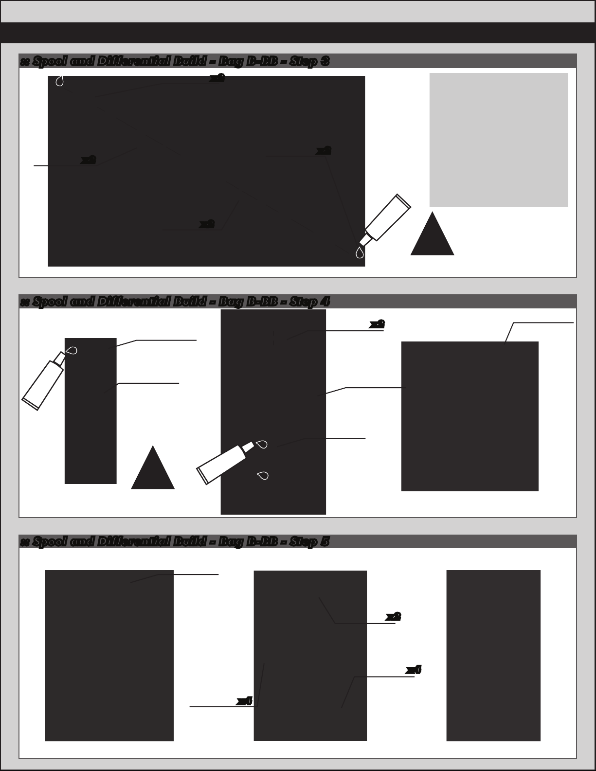
:: Spool and Differential Build - Bag B-BB - Step 3
31341
TC6 spool
outdrive
x2
31401
10x15mm
bearing
x2
31162
Shim
31350
M2.5x10mm
fhcs
x2
x2
:: Spool and Differential Build - Bag B-BB - Step 4
31349
TC6 gear
#6588
black grease
diff seals
31346
TC6 gear
diff outdrive
(1 small, 1 big)
31348
TC6 gear
diff shim
31347
TC6 gear
diff case
#1596
thread lock
x2
!
Thread lock
not included!
31348
TC6 gear
diff pin
31349
TC6 gear
diff seals
!
#6588
black grease
Build two
outdrives
:: Spool and Differential Build - Bag B-BB - Step 5
31345
TC6 gear
diff sun
gear
31348
TC6 gear
diff shim
x4
31348
TC6 gear
diff pin
31345
TC6 gear
diff planet
gear
x2
x4
Page 7
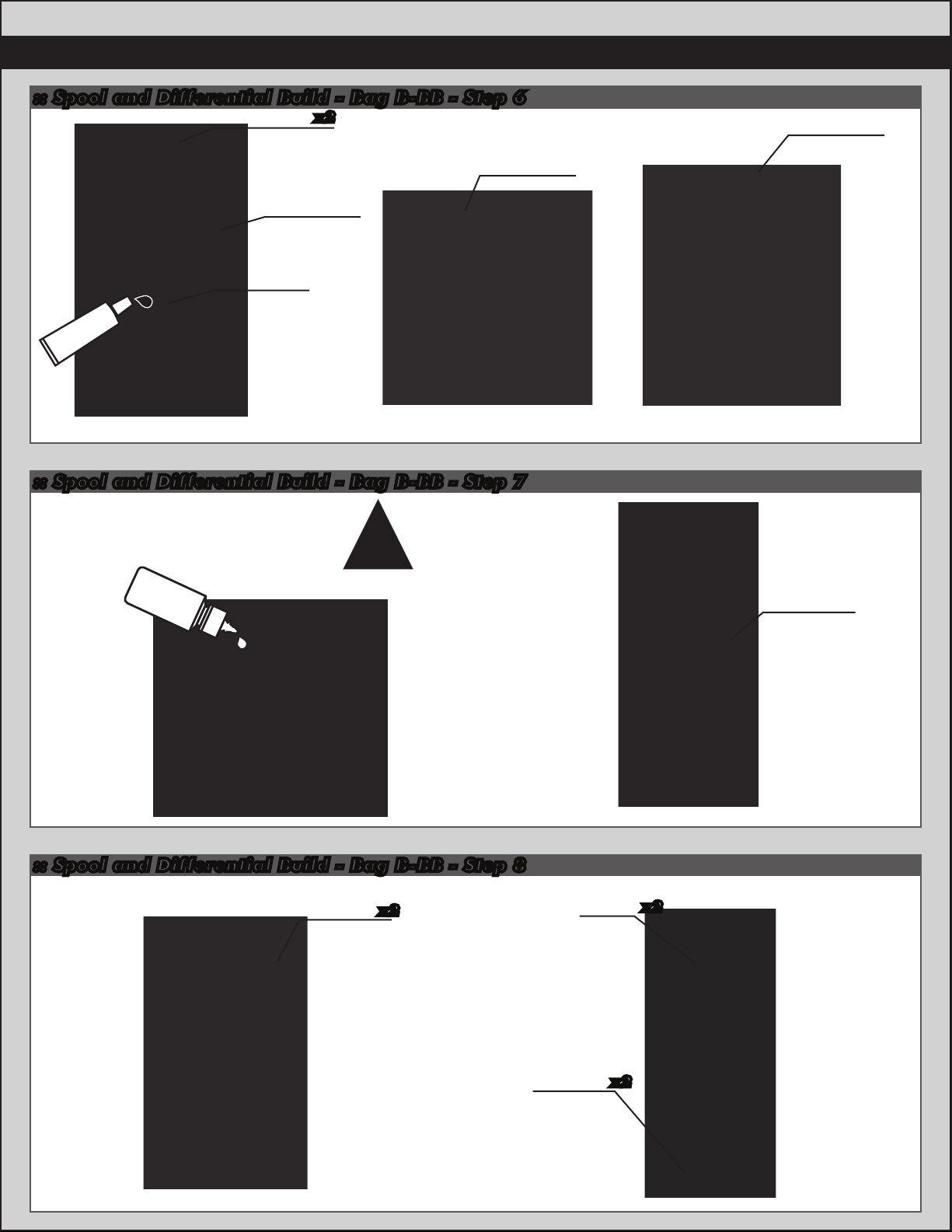
:: Spool and Differential Build - Bag B-BB - Step 6
31348
TC6 gear
diff shim
(1 small, 1 big)
31349
TC6 gear
diff seals
#6588
black grease
x2
31347
TC6 gear
diff pulley
31348
TC6 gear
diff pin
:: Spool and Differential Build - Bag B-BB - Step 7
7
31345
TC6 gear
diff sun
gear
!
Shock oil
#5423
(40wt)
:: Spool and Differential Build - Bag B-BB - Step 8
Fill to top of
cross pins
4675
M2.5x6mm
fhcs
x2
31162
Shim
31347
TC6 gear
diff gasket
x2
10x15mm
bearing
x231401
Page 8
8
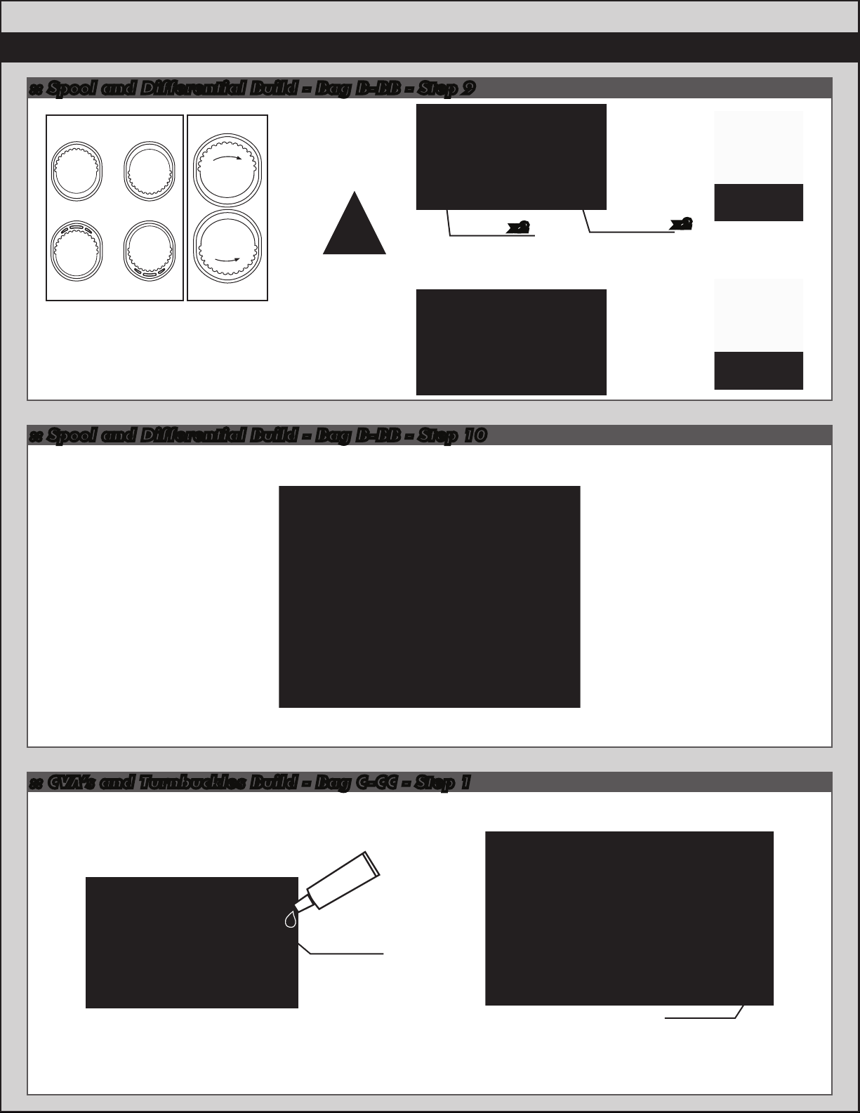
:: Spool and Differential Build - Bag B-BB - Step 9
Belt Tension
Cam Position
Number
Left Side
Mid-Low
161
Mid-High
31615
Low
Note!
Always use the same
cam position on both
sides of the car.
High
17 32
View from left
side of car
!
Use belt tension
position 7 for
standard setup.
Right Side
Diff
bearing
cam
:: Spool and Differential Build - Bag B-BB - Step 10
x2
31615
Cam
holder
(mid-low)
x2
:: CVA’s and Turnbuckles Build - Bag C-CC - Step 1
#6588
black grease
31367
31368
TC6.1 CVA
bones
TC6.1 CVA
coupler
31367
CVA
cross pin
31369
TC6.1 CVA
axle
Page 9
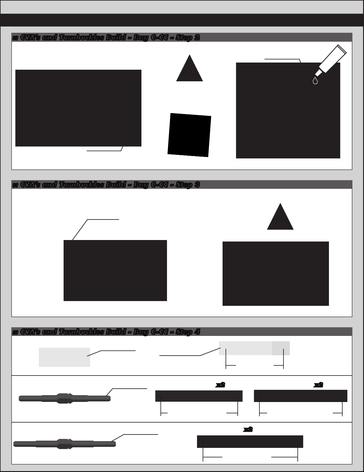
:: CVA’s and Turnbuckles Build - Bag C-CC - Step 2
!
Note!
Align the gap in the
pin retainer to be
opposite of the CVA
pin.
31237
retaining
clip
:: CVA’s and Turnbuckles Build - Bag C-CC - Step 3
31500
M3x2.5mm
setscrew
!
Thread lock
not included!
9
#1596
thread lock
31238
CVA blade
:: CVA’s and Turnbuckles Build - Bag C-CC - Step 4
Servo Turnbuckle
Camber Turnbuckle
1418
0.825”
turnbuckle
1402
1.375”
turnbuckle
31305
Turnbuckle
eyelet
Front Rear
!
Build four
CVA’s
34.65mm
x2 x2
Steering Turnbuckle
1405
1.875”
turnbuckle
46mm
49.50mm
x2
57mm
Page 10
10
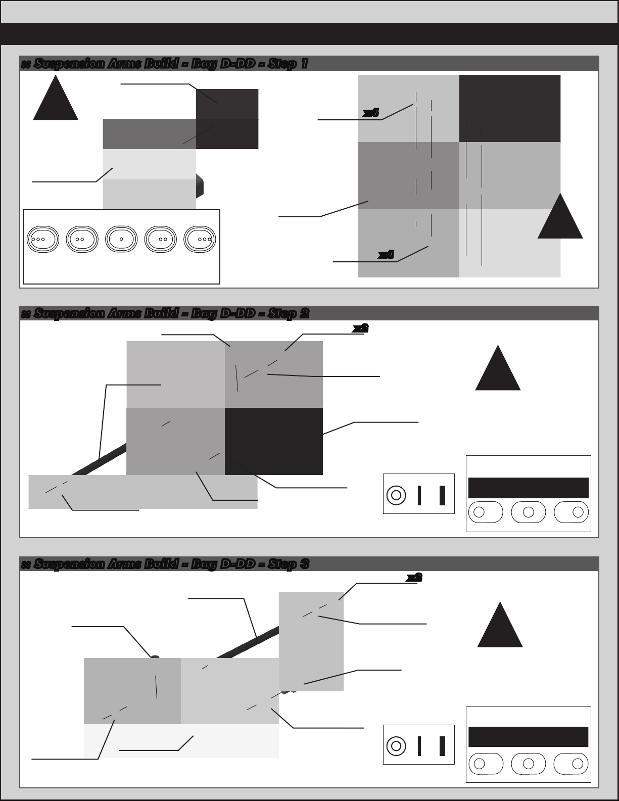
:: Suspension Arms Build - Bag D-DD - Step 1
31620
TC6.2 arm
mount insert
!
Build four
inner arm
mounts
31619
TC6.2 Inner
arm mount
Arm Mount Inserts
-3 DOT
-1 °
:: Suspension Arms Build - Bag D-DD - Step 2
-2 DOT
-1/2 °
Negative to the inside of vehicle.
Positive to the outside of vehicle.
1 DOT
0 °
(1 dot)
+2 DOT
+1/2 °
M4x8mm
setscrew
+3 DOT
+1 °
25227
31600
TC6.2
chassis
4617
Front
bulkhead
shim
(0.5mm)
31541
M3x6mm
fhcs
31621
x2
Inner hinge
pin ball
x4
x4
!
Install
front and
rear
31221
Inner
hinge pin
31356
Front
suspension
arm insert
31200
Wheelbase
shim (1mm)
31280
5mm
ballstud
(short)
:: Suspension Arms Build - Bag D-DD - Step 3
31221
Inner
25227
M4x8mm
setscrew
31200
Wheelbase
shim (2mm)
31357
Rear
suspension
arm
hinge pin
31200
Wheelbase
shim (2mm)
(B)
31357
Rear
suspension
arm insert
(B)
31356
Front
suspension
arm
Wheel Base Shims
1mm
31621
x2
Inner hinge
pin ball
31200
Wheelbase
shim (1mm)
31283
5mm
ballstud
(long)
Wheel Base Shims
1mm
2mm
2mm
!
Build left
and right
sides
Suspension Arm Insert
(front)
A
A
B
!
Build left
and right
sides
Suspension Arm Insert
(rear)
A
C
B
C B A
C
B
C
Page 11
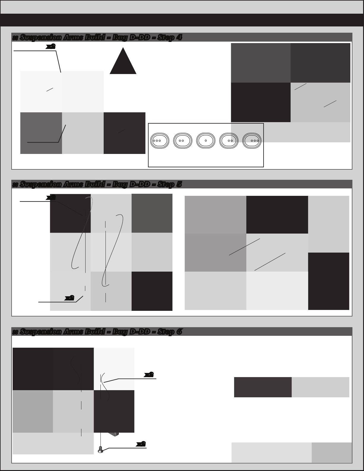
:: Suspension Arms Build - Bag D-DD - Step 4
31620
TC6.2 arm
mount insert
(1 dot)
x2
!
Build two, one for
front, one for rear.
Both with 1 dot inserts
-2 DOT
Negative to the inside of vehicle.
Positive to the outside of vehicle.
31618
TC6.2
Outer Arm
Mount
-3 DOT
-1 °
:: Suspension Arms Build - Bag D-DD - Step 5
Arm Mount Inserts
1 DOT
-1/2 °
0 °
+2 DOT
+1/2 °
11
+3 DOT
+1 °
4617
x2
Front
bulkhead
shim
(0.5mm)
31541
x2
M3x6mm
fhcs
:: Suspension Arms Build - Bag D-DD - Step 6
Droop:
The standard settings of
6mm front and 5mm rear
will work best in most cases.
Droop is measured just
x2
4617
Front
bulkhead
shim
(0.5mm)
31541
M3x6mm
fhcs
x2
underneath the outer hinge
pin as shown in the photos
to the right.
On bumpy or low grip
surfaces, increase the droop
(going to a lower number on
the droop gauge), this will
help increase traction and
consistency.
Droop adjustments of
0.5mm to 1mm can be
very effective on the track!
Front Droop
Setting: 6mm
Rear Droop
Setting: 5mm
8
7
6
5
4
3
2
1
0
8
7
6
5
4
3
2
1
0
Page 12
12
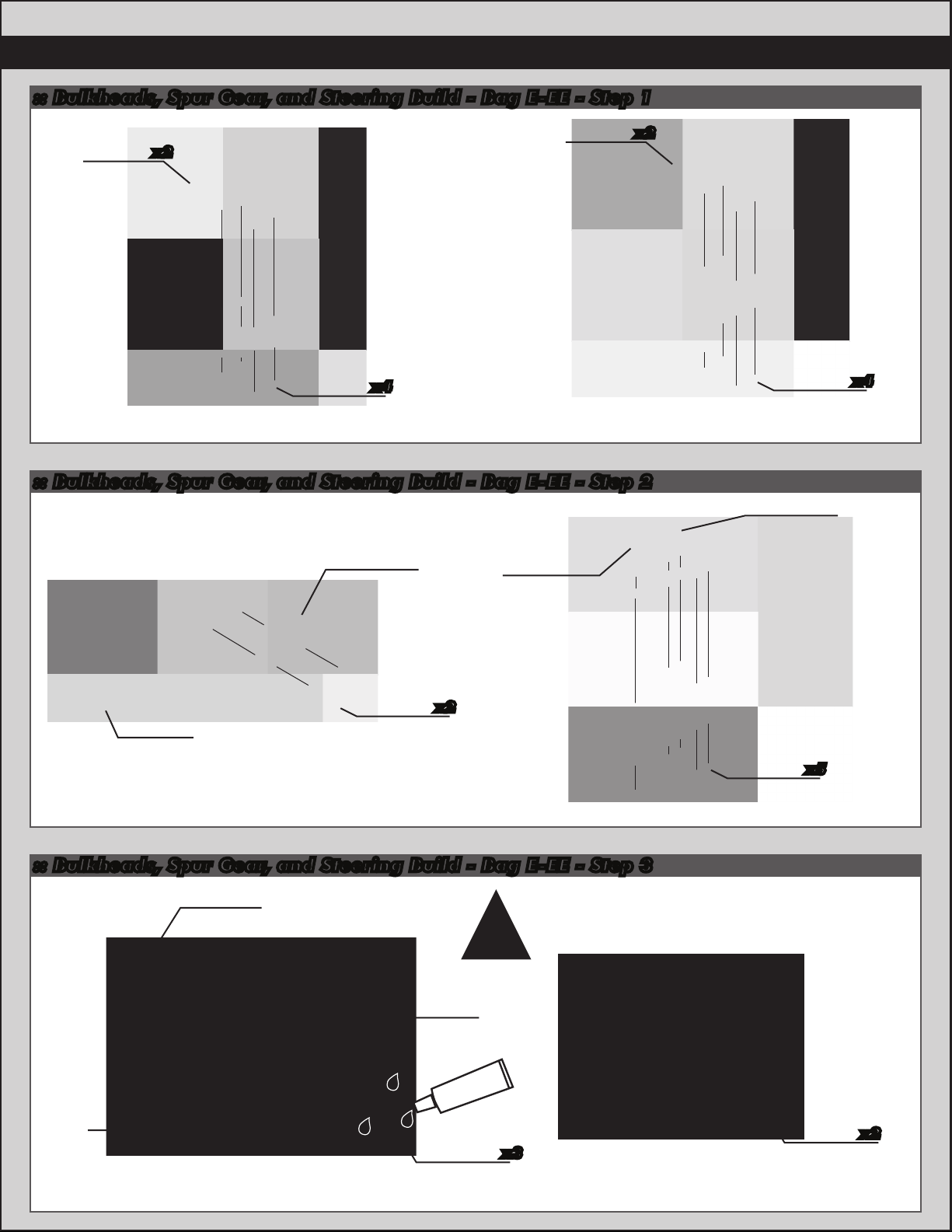
:: Bulkheads, Spur Gear, and Steering Build - Bag E-EE - Step 1
x2
31612
TC6.2
Bulkhead
x2
31540
M3x5mm
fhcs
31612
TC6.2
Bulkhead
x4
:: Bulkheads, Spur Gear, and Steering Build - Bag E-EE - Step 2
31616
TC6.2
spur gear
bulkhead
31617
TC6.2 motor
mount
standoff
31540
M3x5mm
fhcs
31616
TC6.2
spur gear
bulkhead
x4
31617
TC6.2
motor
mount
31532
M3x8mm
bhcs
x2
:: Bulkheads, Spur Gear, and Steering Build - Bag E-EE - Step 3
31314
TC6 spur
31333
TC6
spur gear
(87T / 48P)
gear hub
31319
TC6 spur gear
clamping ring
31530
M3x5mm
!
Thread lock
not included!
#1596
thread lock
x3
bhcs
31540
M3x5mm
fhcs
TC6 spur
x5
31320
pulley
(20T)
x2
Page 13
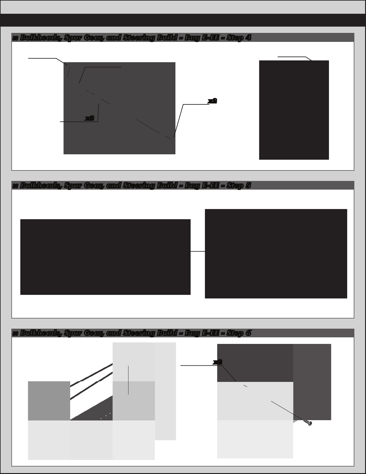
:: Bulkheads, Spur Gear, and Steering Build - Bag E-EE - Step 4
13
31160
3mm
E-clip
31331
4x8x3
flanged
bearing
31315
TC6 spur
gear shaft
x2
31162
Shim
x2
:: Bulkheads, Spur Gear, and Steering Build - Bag E-EE - Step 5
Rear Belt
31160
3mm
E-clip
Front Belt
31188
Rear belt
31187
Front belt
:: Bulkheads, Spur Gear, and Steering Build - Bag E-EE - Step 6
x231521
M2.5x8mm
bhcs
Page 14

14
Slide belt over
gear diff pulley!
!
:: Bulkheads, Spur Gear, and Steering Build - Bag E-EE - Step 7
!
Slide belt over
spool pulley!
:: Bulkheads, Spur Gear, and Steering Build - Bag E-EE - Step 8
x2
31531
M3x6mm
bhcs
x4
31286
FT ballstud
washer,
aluminum
(2mm)
x2
31280
Ballstud,
short,
5mm
!
Slide belt over
gear diff pulley!
31613
TC6.2
bearing
cap (A)
31614
TC6.2
bearing
cap (B)
:: Bulkheads, Spur Gear, and Steering Build - Bag E-EE - Step 9
31286
FT ballstud
washer,
aluminum
(1mm)
31614
TC6.2
bearing
cap (B)
x2
31280
Ballstud,
short,
5mm
31613
TC6.2
bearing
cap (A)
x2
31531
M3x6mm
bhcs
x4
Page 15

:: Bulkheads, Spur Gear, and Steering Build - Bag E-EE - Step 10
Note!
Place top
plate between
the front belt.
!
!
15
!
Note!
Place top
plate between
the front belt.
31601
TC6.2
top plate
!
Belt hidden for
view clarity!
M3x5mm
bhcs
x931530
:: Bulkheads, Spur Gear, and Steering Build - Bag E-EE - Step 11
31531
M3x6mm
bhcs
x2
31604
TC6.2 front
shock tower
31250
Shock
bushing
x2
31541
M3x6mm
fhcs
x4
:: Bulkheads, Spur Gear, and Steering Build - Bag E-EE - Step 12
31531
M3x6mm
bhcs
31250
Shock
bushing
x2
x2
31605
TC6.2 rear
shock tower
31541
M3x6mm
fhcs
x4
Page 16

16
:: Bulkheads, Spur Gear, and Steering Build - Bag E-EE - Step 13
31374
TiN 3.25mm
31286
FT ballstud
washer,
aluminum
(1mm)
x2
ballstud,
short neck
31610
TC6.2
steering
bellcrank
x2
31611
31283
Ballstud,
long,
5mm
x2
TC6.2
steering
rack
31609
TC6.2
steering
bellcrank
post
x2
:: Bulkheads, Spur Gear, and Steering Build - Bag E-EE - Step 14
31611
TC6.2 steering
rack hat
bushing
25211
M3x10mm
bhcs
x2
x2
31609
TC6.2 steering
bellcrank post
spacer
!
Top Plate and
Belts hidden for
view clarity!
x2
31403
Bearing,
4 x 7mm
31540
M3x5mm
fhcs
x8
x2
:: Steering / Caster Blocks Build - Bag F - Step 1
31360
TC6.1
steering
blocks
!
Note offset
(Left side shown)
31280
5mm
ballstud
(short)
31370
TC6.1
axle crush
tube
25237
5x10mm
bearing
!
Build left
and right
sides
x2
Page 17

:: Steering / Caster Blocks Build - Bag F - Step 2
31162
Axle shim
:: Steering / Caster Blocks Build - Bag F - Step 3
!
Build left
and right
sides
31511
M2x5mm
shcs
17
31112
1/16” x 5/16”
dowel pins
31234
Clamping
wheel hex
31358
TC6.1 caster
blocks
(left and right)
!
31358
!
TC6.1 caster
block
inserts
(4 deg)
Use the supplied
symmetric inserts to
select caster angle. When
viewed from the front, the
number should be located
on the top side of the pin,
as shown in the view to the
right. When viewed from
the rear, the number should
be located on the bottom.
!
x2
:: Steering / Caster Blocks Build - Bag F - Step 4
Use small amount ca glue to
permanently secure the caster
RACERS TIP:
block inserts in the caster
Left
4
blocks.
Right
4
31214
Caster
block
bushing
x2
!
Build left
and right
sides
Page 18

18
:: Steering / Caster Blocks Build - Bag F - Step 5
31284
8mm
ballstud
(long)
!
Build left
and right
sides
:: Steering / Caster Blocks Build - Bag F - Step 6
31532
M3x8mm
bhcs
!
Build left
and right
sides
31510
M2x4mm
bhcs
:: Steering / Caster Blocks Build - Bag F - Step 7
!
Orient the notch
to the left throughout
the car. The notch
indicates which end has
the left hand threads!
31222
Outer
hinge pin
Page 19

:: Steering / Caster Blocks Build - Bag F - Step 8
!
:: Steering / Caster Blocks Build - Bag F - Step 9
19
It is important that the turnbuckle eyelets move freely
once snapped on to the ballstud. If the fit is too tight,
the car handling will be inconsistent. To check, grab
turnbuckle eyelet with fingers and rotate the cup. If
there is resistance, lightly squeeze ball cup with needle
nose pliers as shown and test again. It is important
that the ball cup be snapped onto the ballstud before
squeezing with needle nose pliers. Be sure to check
and adjust the fit for each ball cup that is installed.
31359
TC6.1
rear hub
carrier
31359
TC6.1
rear hub
carrier
inserts
(0 deg)
x2
!
!
!
Use the supplied
symmetric inserts to select
rear hub toe angle.
When viewed from the
back, the number should
be located on the outside
of the hinge pin, as shown
in the view to the right.
When viewed from the
front, the number should
be located on the inside
of the hinge pin.
:: Steering / Caster Blocks Build - Bag F - Step 10
31284
8mm
ballstud
(long)
31286
Aluminum
ballstud
washer
(2mm)
31370
TC6.1
axle crush
tube
25237
5x10mm
bearing
x2
RACERS TIP:
Use small amount of ca
0
glue to permanently secure
the rear hub inserts in the
hubs.
0
RightLeft
31162
Axle shim
Page 20

20
Build left
and right
sides
!
:: Steering / Caster Blocks Build - Bag F - Step 11
31112
1/16” x 5/16”
dowel pins
31234
Clamping
wheel hex
!
Build left
and right
sides
:: Steering / Caster Blocks Build - Bag F - Step 12
31511
M2x5mm
shcs
!
Build left
and right
sides
31510
M2x4mm
bhcs
31222
Outer
hinge pin
!
Orient the notch
to the left throughout
the car. The notch
indicates which end has
the left hand threads!
:: Steering / Caster Blocks Build - Bag F - Step 13
M3x5mm
bhcs
x231530
x231530
M3x5mm
bhcs
Page 21

:: Bumper, Anti-Roll Bar and Electronics Build - Bag G-GG - Step 1
21
4673
M2.5x4mm
x3
bhcs
!
Transponder
not included!
31623
TC6.2
bumper
:: Bumper, Anti-Roll Bar and Electronics Build - Bag G-GG - Step 2
x2
3897
Pivoting
body mounts
x2
1736
FT body
clips, blue
(short)
31625
TC6.2 front
body posts
x2
31624
TC6.2
foam
bumper
25203
M3x12mm
fhcs
x2
31623
TC6.2
bumper
brace
25201
M3x8mm
fhcs
x3
:: Bumper, Anti-Roll Bar and Electronics Build - Bag G-GG - Step 3
31532
M3x8mm
bhcs
x2
3897
Pivoting
body mounts
x2
1736
FT body
clips, blue
(short)
x2
25201
M3x8mm
fhcs
x2
31625
TC6.2 rear
body posts
x2
Page 22

22
:: Bumper, Anti-Roll Bar and Electronics Build - Bag G-GG - Step 4
6338
Antenna
tube & cap
31626
Antenna
31626
TC6.2 lipo
brace
31626
TC6.2 lipo
brace
(offset)
31541
M3x6mm
fhcs
x4
:: Bumper, Anti-Roll Bar and Electronics Build - Bag G-GG - Step 5
8828
Anti roll
bar cups
mount
31626
Inner lipo
brace
M3x2.5mm
set screw
Top Plate and
Belts hidden for
31540
M3x5mm
fhcs
31500
!
view clarity!
x3
!
31269
Anti roll
bar pivot
mount
31058
Anti roll
bar
ballstud
:: Bumper, Anti-Roll Bar and Electronics Build - Bag G-GG - Step 6
Front
31364
1.1mm
roll bar
(yellow)
31628
Anti roll
bar pivot
Build four antiroll bar mounts
Anti Roll Bar
Link Adjust
x2
31500
M3x2.5mm
set screw
x4
ment
14mm
Anti Roll Bar
Color/Size Chart
Green
White
Blue
Yellow
Red
M2x5mm
0.8mm
0.9mm
1.0mm
1.1mm
1.2mm
31511
shcs
x2
!
Install four
anti-roll bar mounts,
two for the front
arms and two for
the rear arms.
31627
TC6.2
anti roll
bar tube
!
Shrink the colored
heat shrink tubing to
the anti roll bar!
Page 23

:: Bumper, Anti-Roll Bar and Electronics Build - Bag G-GG - Step 7
x2
Rear
Anti Roll Bar
Color/Size Chart
Green
White
Blue
Yellow
Red
0.8mm
0.9mm
1.0mm
1.1mm
1.2mm
31364
0.9mm
roll bar
(white)
31627
TC6.2
anti roll
bar tube
31365
Anti roll
bar mounts
31511
M2x5mm
shcs
x2
:: Bumper, Anti-Roll Bar and Electronics Build - Bag G-GG - Step 8
31628
Anti roll
bar pivot
M3x2.5mm
set screw
x2
31500
x4
!
Shrink the colored
heat shrink tubing to
the anti roll bar!
23
31365
x2
Anti roll
bar mounts
:: Bumper, Anti-Roll Bar and Electronics Build - Bag G-GG - Step 9
Steering Servo Chart
Associated
Airtronics
Airtronics
Hitec
Hitec
JR
JR
Futaba
Futaba
Futaba
KO
* Not all servo’s are listed
* Make sure servo linkage clears the servo through full travel in both
directions. Use #7336 servo spacers to adjust servos position as necessary.
XP-1015, XP-1313
94102
94738, 94157, 94158, 94257, 94258, 94357,
94358, 94452, 94453, 94751, 94755
HS-5625MG, HS-5645MG, HS625MG, HS645MG
HS-322HD, HS-325HB, HS-965, HS-985MG,
HS-5965, HS-5985MG, HS-425BB, HS-422
Z4725, Z4750, Z2750, Z8450, Z8550, NES-4750
Z250, Z550
S9204, S9250, S9450, S148
S3003, S9202, S9101
S9404
PS-401, PS-2001, PS-2004, PS -2015, PS-2173,
PS-2174, PS-2123, PS-2143, PS -2144
# 89007
servo arm
F
A
A
H
H
J
J
F
F
F
J
!
31286
Aluminum
ballstud washer
(1mm, 2mm)
31285
10mm
ballstud
(long)
Drill top hole to
2.5mm, then install
ballstud and locknut
31511
M2x5mm
shcs
FT M3 Locknut,
blue aluminum
89007
Servo
horn
x2
31550
89007
Servo
horn ring
Page 24

24
:: Bumper, Anti-Roll Bar and Electronics Build - Bag G-GG - Step 10
7336
Servo
spacer
x2
!
Use screw that was included
with your servo.
Servo not included!
31532
M3x8mm
bhcs
x4
:: Bumper, Anti-Roll Bar and Electronics Build - Bag G-GG - Step 11
31530
M3x5mm
bhcs
x5
.250x.125x.015
washer
7337
x4
31622
TC6.2
servo
mounts
x2
31608
TC6.2 servo
mount brace
31540
M3x5mm
fhcs
!
Top Plate
hidden for
view clarity!
x2
:: Bumper, Anti-Roll Bar and Electronics Build - Bag G-GG - Step 12
!
Receiver not
included!
!
ESC not included!
6727
Servo tape
6727
Servo tape
Page 25

:: Bumper, Anti-Roll Bar and Electronics Build - Bag G-GG - Step 13
Gearing will depend on the
motor and track size.
Gear chart on page 29.
Motor, pinion gear, and set
screw are not included!
!
25
31286
Aluminum
ballstud
washer
(1mm)
x2
31532
M3x8mm
bhcs
x2
:: Bumper, Anti-Roll Bar and Electronics Build - Bag G-GG - Step 14
!
Use strapping tape to
secure battery into chassis.
Wrap the tape around the
#31626 LiPo brace an back
onto itself.
Battery tape not included!
Battery and strapping
tape not included!
!
:: Bumper, Anti-Roll Bar and Electronics Build - Bag G-GG - Step 15
!
Wheels, tires, and inserts
not included!
91148
M4
locknut
x4
Page 26

26
:: Tuning Tips
Tips for Beginners:
Before making any changes to the standard setup, make sure you can get around the track without crashing. Changes to your car
will not be beneficial if you can’t stay on the track. Your goal is consistent laps.
Once you can get around the track consistently, start tuning your car. Make only ONE adjustment at a time, testing it before making
another change. If the result of your adjustment is a faster lap, mark the change on the included setup sheet (make additional
copies of the sheet before writing on it). If your adjustment results in a slower lap, revert back to the previous setup and try another
change.
When you are satisfied with your car, fill in the setup sheet thoroughly and file it away. Use this as a guide for future track days or
conditions.
Ride Height:
The standard starting point for ride height is 5.0mm (keep in mind that your local track may have minimum ride height
requirements). You can slightly raise the rear relative to the front to give the car more steering. Raise the car slightly for tracks
with large bumps.
Battery Placement:
For most cases, run the battery in the standard forward position. Typically this will be the most stable and easiest to drive. Try
moving the battery back if you encounter a low traction surface by switching LiPo braces front to back.
Wheelbase:
Wheel Base Shims
Lengthening the front will reduce steering, shortening the front will increase steering. Shortening the rear will
1mm
increase rear grip, lengthening the rear will decrease rear traction.
2mm
Rear Toe-In:
The TC6.2 allows rear toe adjustments in two positions: inner hinge pin, and outer hinge pin at the rear hub. In general, decreasing
rear toe-in will decrease rear traction and increase corner speed.
-3 DOT
Rear toe-in can be adjusted by 0.5° increments at the inner hinge pin with
supplied arm mount inserts (see chart to right). Standard toe-in angle for
inner hinge pin when using same insert front and rear is 3°.
-1 °
Standard insert used is 1 dot.
Use rear hub inserts to change toe at the outer hinge pin by 0.5° increments.
Note the number on hub insert should be on outside of hinge pin for proper installation.
Ackermann & Steering Rate:
Ackermann refers to the relative angle difference between the front wheels as they are
turned to steer the car. The outside wheel will turn less than the inside wheel in most
conditions. Settings with more Ackermann will have a bigger difference in wheel angle,
causing the outside wheel to turn less. Likewise, settings with less Ackermann will cause
the outside wheel to turn more.
Increasing the Ackermann will smooth out the steering and is used most often on high
traction surfaces such as carpet. This is a result of the reduced outside wheel angle.
Settings with reduced Ackermann will help to increase corner entry steering, and are
typically used when running a spool in the front.
Arm Mount Inserts
-2 DOT
-1/2 °
Negative to the inside of vehicle.
Positive to the outside of vehicle.
1 DOT
0 °
Steering
Block
Position
B
B
B
A
+2 DOT
+1/2 °
Steering
Rack
Shims
2mm
1mm
0mm
2mm
+3 DOT
+1 °
Less Ackermann
STD
The chart to the right lists the different Ackermann options.
A
B
Steering Block
A
A
1mm
0mm
More Ackermann
Page 27

27
:: Tuning Tips
Caster:
Caster describes the angle of the kingpin from vertical while looking from the side of the car. Positive caster means the top of the
kingpin leans rearward. Negative caster means the kingpin is leaning towards the front of the car. Since caster is measured at the
wheel, it is affected by running any inclination in your inner arm mount. Kick-up adds (+) caster, and anti-dive adds (-) caster.
When figuring out your caster at the wheel, add the number of degrees of kick-up or anti-dive and add it to the degree caster blocks
you have on the car.
Typically for most racing surfaces, 4 degrees caster is the normal starting point for the Team. From there, increase caster to reduce
mid to exit steering and make the front end less responsive. Conversely, decreased caster gives a more responsive feel and more exit
steering.
Droop:
The standard settings of 6mm front and 5mm
rear will work best in most cases. Droop is
measured just underneath the outer hinge pin
as shown in the photos to the right.
On bumpy or low grip surfaces, increase the
droop (going to a lower number on the droop
gauge), this will help increase traction and
consistency.
Droop adjustments of 0.5mm to 1mm can be
very effective on the track!
Increase IncreaseDecrease Decrease
Front Droop
Setting: 6mm
4
3
2
1
0
Rear Droop
Setting: 5mm
8
7
6
5
0
4
3
2
1
8
7
6
5
Camber Link Position:
The camber link is used to set static camber at ride height, but it is also an effective setting to adjust roll center height and camber
gain. The TC6.2 has three optimized length positions at the front, and six at the rear, for a wide range of camber gain adjustments.
All camber link mounting positions use vertical ballstuds that can be shimmed for precise roll center height adjustments.
Longer links will produce less camber gain, stiffening that particular end of the car in roll. These are particularly effective on large
tracks with big sweeping corners. Shorter links will give more camber gain, softening that end of the car in roll. This will make the
car more aggressive, and is a good setting for smaller indoor tracks with high grip levels.
The angle of the camber link will make fine adjustments to the roll center height. Typically the camber link will be no more than
parallel to the suspension arm with the inboard side of the link lower than the outboard side. As the inboard side of the camber link
is moved down, the roll center goes up, stiffening that end of the car. Camber link angle is a good adjustment to help fine tune the
balance of the car to the track by setting the front and rear at slightly different angles.
Arm Mount Position:
The TC6.2’s arm mount system allows for maximum adjustability for all track and racing conditions. Independent inner and outer arm mounts
with interchangeable inserts provide multiple pin configurations... flat, or with angle, to give a host of kickup/tow and pin width options.
Use the TC6.2’s included arm mount inserts to adjust pin width and angle. The arm
mount inserts are indicated one, two, and three with the corresponding amount of dots
on their exposed face. Each insert will index the hinge pin by 1/2 degree (or 0.43mm).
Standard pin angle is achieved when using the same insert in both the inner and outer
mounts. Rear hinge pin angle is 3° when using the same insert in both inner and outer
mounts.
The chart to the right shows the pin angle change for the right rear pin when using
a 1 dot insert in the inner arm mount.
Pin width can also be adjusted by changing the inserts in the inner and outer mounts
by an equal amount. The standard pin width for the TC6.2 uses 1 dot inserts at all
corners, and is best suited for rubber tire racing.
The TC6.2’s independent inner and outer arm mount system also allows for roll center
height adjustements as well as options for anti-dive/kick-up and anti-squat/pro-squat
hinge pin angles. Precise adjustments can be made by changing the shim thickness
between the arm mounts and chassis.
The standard roll center height uses o.5mm shims on all mounts. This produces a
relatively low roll center with more chassis roll on the corners... typically good for lower
grip conditions such as rubber tires on asphalt. If the grip level is high, try raising the
roll center by using thicker shims between the mounts and chassis.
Anti-dive/kick-up and anti-squat/pro-squat angles can be adjusted by varying the
amount of shims under the inner and outer mounts. A 0.5mm difference will produce
an angle of about 1/2 degree. The following sections briefly describe front and rear
pin angles and their effect on the track.
-3 DOT
-1 °
Negative to the inside of vehicle.
Positive to the outside of vehicle.
4
3
2
1
Arm Mount Inserts
-2 DOT
-1/2 °
1 DOT
0 °
ABC
+2 DOT
+1/2 °
+3 DOT
+1 °
Page 28

28
:: Tuning Tips
Anti-Dive (front):
Anti-dive is a front arm angle where the rear mount is higher than the front mount. Adding anti-dive reduces weight transfer to the
front on deceleration entering corners. It also reduces caster at the wheel.
Kick-Up (front):
Kick-up describes the angle of the front suspension arm, where the front mount is higher than the rear mount. Increasing kick-up will
give more entry steering, as well as increasing caster at the wheel.
Anti-Squat (rear):
Anti-Squat describes a rear arm angle where the front mount is higher than the rear mount. Increasing anti-squat will make the rear
suspension stiffer. It tends to give the car more entry steering and reduce rearward weight transfer on power.
Pro-Squat (rear):
Pro-squat is a rear arm angle where the rear mount is higher than the front mount. Running Pro-Squat will increase rearward
weight transfer on power.
Anti-Roll Bar:
Anti-roll bars are only effective during roll (when the chassis leans from side to side when cornering).
Because of this they isolate a change in the suspensions spring rate in the corners only, and can be a very useful
tuning option.
Anti-roll bars stiffen the spring rate of the suspension during roll movements when cornering. The larger the
roll bar wire, the stiffer the spring rate will be in roll. The chart on the right shows the available anti-roll bar
sizes (as well as their corresponding colors) from the softest on the top, to the stiffest on the bottom.
The standard setup, using yellow front anti-roll bars (1.1mm) and white rear anti-roll bars (0.9mm), is a balanced starting point.
Changing the size of the front or rear anti-roll bars can help to make the chassis more consistent through the corner. Decreasing the
size of the front anti-roll bars will help to increase mid-corner steering, but will tend to be less stable in sweepers. This is a
typical setup for smaller tracks with tighter turns. Increasing the size of the front anti-roll bars will give more stability in the
sweepers, and is better for larger tracks with high speed corners. Increasing the size of the rear ant-roll bars will help add stability
into and through the corner in high traction conditions, but can make the car inconsistent in low traction, or bumpy, surfaces.
Belt Tension:
When altering the differential height, you will need
to adjust the tension of the belt. The following chart
shows suggested starting positions.
TighterLooser Tighter Looser
Left Side
Front
Note! Charts show left side cam positions from the left side of the car. Match right side cam position to left side cam position.
Cam Position
Mid-Low
Low
Left Side
Front
Mid-High
High
Belt Tension
Number
161
17 32
View from left
side of car
Anti Roll Bar
Color/Size Chart
Green
White
Blue
Yellow
Red
Height
High
Mid-High
Front
Height
High
Mid-High
Rear
0.8mm
0.9mm
1.0mm
1.1mm
1.2mm
Pos.
31
28
Mid
Low
Pos.
18
20
Mid
Low
8
5
7
9
Motor Gearing:
The gear charts on the following page show final drive ratio numbers for the TC6.2. Refer to motor manufacturer’s suggested gear
ratio for starting point. You may need to adjust the gearing according to your track size.
The following formula’s can also be helpful in determining final drive ratios and pinion size.
TC6 Internal Ratio = 2.0
# of Teeth on Pinion
Final Drive Ratio
Final Drive Ratio = (# of Teeth Spur) x (Internal Ratio)
# of Teeth on Pinion = (# of Teeth on Spur) x (Internal Ratio)
Page 29

:: Gear Chart 48 Pitch
!
Blank spaces in the gear
charts designates a gear
ratio that will not fit in the
vehicle. Gear fitment will
also depend on the motor
brand.
29
:: Gear Chart 64 Pitch
Page 30

30
:: Shocks
5407
6465
6475
31305
31323
31324
31325
31326
31327
31328
31329
31330
31510
Red O-Rings
Shock Piston, PTFE
Preload Spacers, Collars, Cups
Turnbuckle Eyelet
VCS3 Shock Kit
VCS3 Shock Rebuild
VCS3 Shock Body
VCS3 Shock Collar
VCS3 Shock Bottom Cap
VCS3 Aluminum Cap Retainer
VCS3 Shock Cap
VCS3 Shock Shaft
M2x4mm BHCS
:: Springs
3941
3942
3943
3944
3945
3946
3952
3953
3954
3988
TC Spring, Green, 12.0lbs
TC Spring, Silver, 14.5lbs (Kit)
TC Spring, Blue, 17.0lbs
TC Spring, Gold, 19.5lbs
TC Spring, Red, 22.0lbs
TC Spring, Copper, 25.0lbs
TC Spring, Purple, 30.0lbs
TC Spring, Yellow, 35.0lbs
TC Spring, White, 40.0lbs
TC Spring Set, 1 pr. each
31510
6465
12
14
Pr.
Pr.
Pr.
Pr.
Pr.
Pr.
Pr.
Pr.
Pr.
:: CVA’s
8
1
1
1
2
2
2
2
4
2
6
31328
31329
31324
31325
31327
31324
5407
31324
31327
1
31326
31326
31237
31238
31366
31367
31368
31369
31500
CVA Pin Retaining Clip
CVA Bone Blade
TC6.1 CVA Kit
TC6.1 CVA Rebuild Kit
TC6.1 CVA Bone
TC6.1 Stub Axle
M3x2.5mm Set Screw
31238
31368
31366
:: Anti-Roll Bars
8828
31058
31364
31365
31500
31511
31627
31628
Anti-Roll Bar Cups, Set
Anti-Roll Bar Ballstud,blue aluminum
TC6.1 Anti-Roll Bar Wire, Set
TC6.1 Anti-Roll Bar Mounts
M3x2.5mm Set Screw
M2x5mm SHCS
TC6.2 Anti-Roll Bar Tube
TC6.2 Anti-Roll Bar Kit
2
8
1
1
Pr.
Pr.
6
31367
31500
31369
31237
1
2
1
4
6
6
1
1
31324
31330
Front
3942
Rear
3942
6475
31500
31364
31500
31628
31269
31511
31500
31305
31627
:: Shock Fluid :: Turnbuckles
5420
5421
5422
5423
5424
5425
5426
5427
5428
5429
5430
5431
5432
5433
5434
5435
5436
5437
5438
10 Weight Silicone Shock Fluid
20 Weight Silicone Shock Fluid
30 Weight Silicone Shock Fluid
40 Weight Silicone Shock Fluid
22.5 Weight Silicone Shock Fluid
80 Weight Silicone Shock Fluid
27.5 Weight Silicone Shock Fluid
15 Weight Silicone Shock Fluid
25 Weight Silicone Shock Fluid
35 Weight Silicone Shock Fluid
45 Weight Silicone Shock Fluid
55 Weight Silicone Shock Fluid
32.5 Weight Silicone Shock Fluid
37.5 Weight Silicone Shock Fluid
42.5 Weight Silicone Shock Fluid
50 Weight Silicone Shock Fluid
60 Weight Silicone Shock Fluid
70 Weight Silicone Shock Fluid
47.5 Weight Silicone Shock Fluid
2oz.
2oz.
2oz.
2oz.
2oz.
2oz.
2oz.
2oz.
2oz.
2oz.
2oz.
2oz.
2oz.
2oz.
2oz.
2oz.
2oz.
2oz.
2oz.
1402
1405
1418
31305
FT Blue Titanium Turnbuckles 1.375”
FT Blue Titanium Turnbuckle 1.875”
FT Blue Titanium Turnbuckle 0.825”
Turnbuckle Eyelet
31305 31305
31305 31305
31305 31305
31058
31364
1418
1402
1405
8828
31511
31511
31511
31365
31365
31500
31628
Pr.
Pr.
Pr.
14
Page 31

:: Front Spool
31162
31175
31339
31341
31342
31350
31401
31510
31615
Axle Shim Kit
Oneway/Spool Pulley
TC6 Spool Kit
TC6 Spool Outdrives
TC6 Spool Hub
M2.5x10mm FHCS
10 x 15mm Bearing
M2x4mm BHCS
TC6.2 Diff Bearing Cam Set
31
1
1
1
4
1
6
2
6
1
31350
31401
31341
31342
31162
31175
31510
31162
31341
:: Rear Gear Differential
4675
31162
31344
31345
31346
31347
31348
31349
31401
31615
M2.5 X .45 X 6 FHCS
Axle Shim Kit
TC6 Gear Diff
TC6 Gear Diff Rebuild
TC6 Gear Diff Outdrives
TC6 Gear Diff Case,
O-Ring, Pulley
TC6 Gear Diff Pins & Shims
TC6 Gear Diff Seals
10 x 15mm Bearing
TC6.2 Diff Bearing Cam Set
See page 30 for shock fluids for use
with the TC gear differential.
6
1
1
1
2
1
1
1
2
1
31401
31345
31348
31615
31346
31348
31349
31345
31348
31348
31162
31348
31615
31348
31345
31345
31349
31345
31347
31349
31348
31349
31510
31348
31401
31348
4675
31615
31347
31349
31162
31350
31615
31348
31346
4675
31401
:: Spur Gear Assembly
31160
31162
31314
31315
31319
31320
31331
31333
31521
31530
3mm E-Clip
Axle Shim Kit
TC6 Spur Gear Hub
TC6 Spur Gear Shaft
TC6 Spur Clamping Ring
TC6 Spur Pulley (20T)
4x8x3mm Flanged Bearing
TC6 Spur Gear (87T/48P)
M2.5x0.5x8mm BHCS
M3x0.5x5mm BHCS
6
1
1
1
1
2
2
1
6
6
31521
31162
31160
31320
31331
31333
31314
31319
31530
31530
31331
31320
31315
31162
31160
31521
Page 32

32
:: Steering Bellcrank and Servo Mounts
7336
7337
25211
31283
31286
31374
31403
31530
31532
31540
31550
31608
31609
31610
31611
31622
89007
Steering Servo Mount Kit
.250” x.125” x.015” Washer
M3x10mm BHCS
5mm Ballstud, long
Aluminum Ballstud Washers, Set
FT TiN 3.25mm Ballstud, short
4x7mm Bearing
M3x5mm BHCS
M3x8mm BHCS
M3x5mm FHCS
FT M3 Locknut, blue aluminum
TC6.2 Servo Mount Brace
TC6.2 Steering Bellcrank Post Set
TC6.2 Steering Bellcrank
TC6.2 Steering Rack Set
TC6.2 Servo Mount Set
Steering Servo Horn & Ring
:: Front Bumper
1736
3897
4673
25201
25203
31623
31624
31625
FT Body Clips, short
Pivoting Body Mounts, Set
M2.5x4mm BHCS
M3x8mm FHCS
M3x12mm FHCS
TC6.2 Bumper Set
TC6.2 Foam Bumper
TC6.2 Body Post Set
20
20
1
4
20
31611
6
1
31403
2
2
6
6
6
6
31403
1
1
1
25211
1
1
1
6
1
6
1
1
1
31540
31609
31403
31403
31609
31283
25201
31610
31286
31285
31374
31550
89007
31532
31611
31286
1736
31625
31530
31608
7336
7337
31540
31532
3897
31530
31622
7336
7337
3897
1736
:: Front and Rear Shock Towers
1736
3897
31250
31280
31286
31530
31531
31532
31541
31604
31605
31613
31614
31625
FT Body Clips, short
Pivoting Body Mounts, Set
Shock Bushing
5mm Ballstud, short
Aluminum Ballstud Washers, Set
M3x5mm BHCS
M3x6mm BHCS
M3x8mm BHCS
M3x6mm FHCS
TC6.2 Front Shock Tower
TC6.2 Rear Shock Tower
TC6.2 Bearing Cap (A)
TC6.2 Bearing Cap (B)
TC6.2 Body Post Set
6
1
4
6
1
6
6
6
6
1
1
1
1
1
31250
31530
31280
31286
31613
31541
31530
31531
31623
31531
31250
31280
31286
31624
31531
31604
31532
31623
25203
1736
31250
4673
31625
25201
25203
3897
31625
3897
31530
1736
31541
31625
31531
31531
31531
31614
31531
31605
31531
31532
31530
31250
Page 33

:: Front Bulkhead
25227
25237
31112
31162
31200
31214
31221
31222
31234
31280
31284
31356
31358
31360
31370
31510
31511
31532
31540
31612
31621
91148
M4x8mm Setscrew
5x10mm Bearing
1/16” x 5/16” Dowel Pins
Axle Shim Kit
Wheelbase Shim Set
Caster Block Bushing
Inner Hinge Pin Set
Outer Hinge Pin Set
Clamping Wheel Hex
5mm Ballstud, short
8mm Ballstud, long
TC6.1 Front Arms
TC6.1 Caster Blocks
TC6.1 Steering Blocks
TC6.1 Axle Crush Tubes
M2x4mm BHCS
M2x5mm SHCS
M3x8mm BHCS
M3x5mm FHCS
TC6.2 Bulkhead
TC6.2 Inner Hinge Pin Ball Set
M4 Locknut, with flange and
knurl
20
2
8
1
1
Pr.
1
1
4
6
6
Pr.
Pr.
Pr.
4
6
6
6
6
1
1
8
31358
31532
31621
31284
31200
31358
31358
25237
31356
31280
31214
31214
25227
31510
31370
31222
31280
31360
31162
31511
33
31621
31200
31221
31356
31612
31540
31540
25237
31112
31234
91148
:: Rear Bulkhead
25227
25237
31112
31162
31200
31221
31222
31234
31283
31284
31286
31357
31359
31370
31510
31511
31540
31612
31621
91148
M4x8mm Setscrew
5x10mm Bearing
1/16” x 5/16” Dowel Pins
Axle Shim Kit
Wheelbase Shim Set
Inner Hinge Pin Set
Outer Hinge Pin Set
Clamping Wheel Hex
5mm Ballstud, long
8mm Ballstud, long
Aluminum Ballstud Washers, Set
TC6.1 Rear Arms
TC6.1 Rear Hub Carrier
TC6.1 Axle Crush Tubes
M2x4mm BHCS
M2x5mm SHCS
M3x5mm FHCS
TC6.2 Bulkhead
TC6.2 Inner Hinge Pin Ball Set
M4 Locknut, with flange and
knurl
20
2
8
1
1
1
1
4
6
6
1
Pr.
Pr.
4
6
6
6
1
1
8
31612
31540
31540
25227
25237
31359
31200
31359
31621
31284
31286
31357
31359
25237
31112
31283
31370
31222
31511
31510
31162
31234
91148
31621
31221
31357
31200
Page 34

34
:: Motor Mount / Battery Mount
31286
31532
31540
31541
31616
31617
31626
Aluminum Ballstud Washers, Set
M3x8mm BHCS
M3x5mm FHCS
M3x6mm FHCS
TC6.2 Spur Gear Bulkhead
TC6.2 Motor Mount Set
TC6.2 LiPo Brace Set
1
6
6
6
1
1
1
31532
31617
31616
31626
31286
31541
31617
31626
31541
31541
31541
:: Chassis / Top Plate / Belts / Antenna / Arm Mounts
4617
6338
31187
31188
31500
31530
31540
31541
31600
31601
31618
31619
31620
31626
Front Bulkhead Shim Set
Antenna Tube 12”, black
Front Belt
Rear Belt
M3x2.5mm Set Screw
M3x5mm BHCS
M3x5mm FHCS
M3x6mm FHCS
TC6.2 Chassis
TC6.2 Top Plate
TC6.2 Outer Arm Mount
TC6.2 Inner Arm Mount
TC6.2 Arm Mount Insert Set
TC6.2 LiPo Brace /Antenna Mount Set
1
1
1
1
6
6
6
6
1
1
1
1
1
1
31540
31530
31540
31530
31601
31616
31540
31532
31530
31620
4617
31541
31620
4617
31541
4617
31541
31620
31618
31619
4617
31541
31188
31187
31500
6338
31600
31626
31626
31540
Page 35

35
:: Pinions / Spur Gears
8253
8254
8255
8256
8257
8258
8259
8260
8261
8263
8264
8265
8266
8267
8268
8269
8270
8271
8272
16T 48P Pinion Gear
17T 48P Pinion Gear
18T 48P Pinion Gear
19T 48P Pinion Gear
20T 48P Pinion Gear
21T 48P Pinion Gear
22T 48P Pinion Gear
23T 48P Pinion Gear
24T 48P Pinion Gear
26T 48P Pinion Gear
27T 48P Pinion Gear
28T 48P Pinion Gear
29T 48P Pinion Gear
30T 48P Pinion Gear
31T 48P Pinion Gear
32T 48P Pinion Gear
33T 48P Pinion Gear
34T 48P Pinion Gear
35T 48P Pinion Gear
1
1
1
1
1
1
1
1
1
1
1
1
1
1
1
1
1
1
1
3921
3922
3923
3924
3994
4462
4615
31332
31333
31334
31335
69T 48P Spur Gear
72T 48P Spur Gear
75T 48P Spur Gear
66T 48P Spur Gear
73T 48P Spur Gear
100T 64P Spur Gear
96T 64P Spur Gear
80T 48P Spur Gear
87T 48P Spur Gear
106T 64P Spur Gear
115T 64P Spur Gear
:: Factory Team and Option Parts
1401
1404
1734
1735
1736
3927
3928
3991
4617
6463
25391
31280
31281
31282
31283
31284
31285
31286
31288
31289
31290
31291
31292
31293
31296
31339
31344
31441
31442
31443
31550
31551
31629
31630
31632
31633
31634
31635
31636
31637
31638
31639
31640
31641
91156
FT Blue Titanium Turnbuckle 1.300”
FT Blue Titanium Turnbuckle 1.775”
FT Blue Body Clip, 4 long, 6 short
FT Blue Body Clip, long
FT Blue Body Clip, short
Radial Heatsink, narrow
Radial Heatsink, wide
TC Aero Dish Wheel 24mm
12R5 Front Bulkhead Shims (0.5, 1.0, 2.0)mm 4 ea
1:10 Blank Shock Pistons
FT 4mm Locknuts, blue
5mm Ballstud, short
8mm Ballstud, short
10mm Ballstud, short
5mm Ballstud, long
8mm Ballstud, long
10mm Ballstud, long
Aluminum Ballstud Washer, Set
Ti Nitride Ballstuds 5mm, short
Ti Nitride Ballstuds 8mm, short
Ti Nitride Ballstuds 10mm, short
Ti Nitride Ballstuds 5mm, long
Ti Nitride Ballstuds 8mm, long
Ti Nitride Ballstuds 10mm, long
TC6 Ballast Weight
TC6 Spool Kit
TC6 Gear Differential Kit
10-Spoke Wheel, black
5-Spoke Wheel, black
5-Spoke Wheel, white
M3 Aluminum Lock Nut, blue
M4 Aluminum Flange Lock Nut, blue
TC6.2 Arm Mount Shims (outer)
TC6.2 Arm Mount Shims (inner)
TC6.2 DCV Kit, builds 2 DCV’s
(requires #91156 Bearings, 5 x 10 x 3)
TC6.2 DCV Rebuild Kit
TC6.2 DCV Stub Axle
TC6.2 DCV Bone
TC6.2 DCV Coupler Tube
TC6.2 Gear Diff Outdrive, Steel
TC6.2 Spool Outdrive, Steel
TC6.2 Belt Tensioner Kit
TC6.2 Fan Mount Set
TC6.2 30mm Cooling Fan
Bearing, 5 x 10 x 3, metal (used with #31632)
2
2
10
4
6
1
1
4
12
8
10
6
6
6
6
6
6
1
2
2
2
2
2
2
1
1
1
2
2
2
6
6
4ea.
2ea.
1
1
1
1
1
1
1
1
1
1
2
:: Lubes & Adhesives
1
1
1
1
1
1
1
1
1
1
1
:: Decals
1105
1596
1597
6588
6591
6636
6727
9787
716
3816
3820
3834
31642
FT Green Slime Shock Lube
FT Locking Adhesive
FT Tire Adhesive, medium
Black Grease - 4cc
S.Diff Lube - 4cc
Silicone Grease - 4cc
Servo Tape
Chassis Protective Sheet
Reedy 2009 Sticker Set
American Bumper Sticker
AE Logo Decal Sheet
AE Blue Embossed Logo Sticker
TC6.2 Decal Sheet
:: XP Electronics
29138
29139
29141
29142
29143
29144
29166
29167
29168
29209
29210
29211
29212
29214
29215
29216
29250
29251
29252
29253
29254
XP SC500 Brushless ESC
XP SC900-BL ESC
XP SC450-BL Brushless ESC
XP ESC Fan Option
XP SC700-BL Brushless ESC
XP SC1200 Brushless ESC
XP DS1313 Digital Servo
XP DS1015 Digital Servo
XP DS1510MG Servo
Gear Set, DS1313
Gear Set, DS1015
Servo Case , DS1313/DS1015
Accessory Pack, DS1313/DS1015
TRS 403-SSi Receiver
XP2G Radio System
XP3G Radio System
XP DS1505 Servo
XP DS1505MG Servo
XP DS1505 Metal Gear Set
XP DS1510 Metal Gear Set
Receiver Antenna
:: Reedy Motors
228
231
232
233
234
235
236
237
238
239
240
241
242
243
244
245
246
954
955
956
957
958
987
Sonic 540 Mach 2 25.5 Comp. Brushless Motor
Sonic 540 Mach 2 21.5 Comp. Brushless Motor
Sonic 540 Mach 2 17.5 Comp. Brushless Motor
Sonic 540 Mach 2 13.5 Comp. Brushless Motor
Sonic 540 Mach 2 10.5 Comp. Brushless Motor
Sonic 540 Mach 2 9.5 Comp. Brushless Motor
Sonic 540 Mach 2 8.5 Comp. Brushless Motor
Sonic 540 Mach 2 8.0 Comp. Brushless Motor
Sonic 540 Mach 2 7.5 Comp. Brushless Motor
Sonic 540 Mach 2 7.0 Comp. Brushless Motor
Sonic 540 Mach 2 6.5 Comp. Brushless Motor
Sonic 540 Mach 2 6.0 Comp. Brushless Motor
Sonic 540 Mach 2 5.5 Comp. Brushless Motor
Sonic 540 Mach 2 5.0 Comp. Brushless Motor
Sonic 540 Mach 2 4.5 Comp. Brushless Motor
Sonic 540 Mach 2 4.0 Comp. Brushless Motor
Sonic 540 Mach 2 3.5 Comp. Brushless Motor
Sonic 540 Stock Rotor 12.3 x 24.2 (7.25)
Sonic 540 Stock Rotor 12.3 x 25.0 (7.25)
Sonic 540 Stock Rotor 12.5 x 25.0 (7.25)
Sonic 540 Modified Rotor 12.2 x 25.0 (5.0)
Sonic 540 Modified Rotor 12.5 x 25.0 (5.0)
Sonic 540 Modified Rotor 13.0 x 25.0 (5.0)
1
1
1
1
1
1
2
1
1
1
1
2
1
1
1
1
1
1
1
1
1
1
1
1
1
1
1
1
1
1
1
1
1
1
1
1
1
1
1
1
1
1
1
1
1
1
1
1
1
1
1
1
1
1
1
1
1
Page 36

36
:: Reedy Batteries and Chargers
302
304
305
309
313
602
604
632
637
736
738
739
AA Alkaline 1.5V (4)
LiPo Pro TX/RX Battery 1600mAh 7.4V Flat
LiFe Pro TX/RX Battery 1300mAh 6.6V Flat
LiPo 65C 7000mAh 7.4V
LiPo 65C 7000mAh 7.4V (5mm)
LiPo 65C 4100mAh 7.4V Shorty
526-S AC/DC 2S-6S LiPo/LiFe Charger
LiPo TX Lightweight Battery 1350mAh 11.1V
LiPo TX Battery - M11X 2500mAh 7.4V
Wolfpack LiPo 5000mAh 7.4V 25C
Wolfpack LiPo 3800mAh 7.4V 25C Shorty
Wolfpack LiPo 5500mAh 7.4V 60C
:: Reedy Accessories
233S
247
248
249
250
605
607
654
655
656
657
658
659
669
941S
959
960
961
962
972
973
978
979
980
981
982
992
Sonic 540/540 Mach 2 Stator 13.5
Sonic 540 Mach 2 Sensor w/bearing
Sonic 540 Mach 2 Steel Bearing Set
Sonic 540 Mach 2 Ceramic Bearing Set
Sonic 540 Mach 2 Insulator Set
Motor Cooling Fans (2)
Charge Harness 2S Standard Pack 4mm
4.0mm Bullet Plugs (2M, 2F)
4.0mm Bullet Plugs (2M, 10F)
4.0mm Bullet Plugs (10F)
4.0mm Bullet Plugs (100F)
4.0mm Bullet Plugs (10M)
4.0mm Bullet Plugs (30M)
5mm Bullet Connector
Sonic 540/540 Mach 2 Stator 17.5
Sonic 540/550 Sensor w/Bearing
Sonic 540/550 Insulator Set (2 pcs.)
Sonic 540/550 Timing Cap w/Screws
Sonic 540/540 Mach 2 Case Screws (3 pcs.)
Sonic 540 Steel Bearing Set
Sonic 540 Ceramic Bearing Set
Flat Sensor Wire 70mm
Flat Sensor Wire 110mm
Flat Sensor Wire 150mm
Flat Sensor Wire 200mm
Flat Sensor Wire 270mm
Sonic 540 Rotor Spacers
:: RePlay Cameras
RP001
RP002
RP021
RP022
RP023
RP024
RP029
RP030
RP032
RP033
RP034
RP036
RP038
RP041
RP042
RP043
RP044
RP045
RP046
RP047
RP048
RP049
RP054
Replay XD1080 Complete Camera System
Replay XD720 Complete Camera System
Replay XD1080 Lens Bezel Kit
Replay XD1080 Clear Lens Cover
Replay XD1080 Lens Bezel & Rear Cap O-Ring
Replay XD Lens Bezel
Replay XD1080 HDMI to Mini-HDMI
Replay XD1080 Mini 8-pin USB Charge Data Cable
USB DC Car Charger 1A Stubby
USB DC Car Charger 500mAh
Micro SDHC USB Reader
3M VHB 4991 Mount Adhesive for SnapTray
3M VHB 5962 Mount Adhesive for SnapTray
Replay XD Suction Cup Arm Mini Clamp
Replay XD Suction Cup Short Arm Base
Replay XD Skateboard Mount
Replay XD VHB SnapTray, Convex
Replay XD VHB SnapTray, Flat
Au Plug for Universal DC Wall Charger
Eu Plug for Universal DC Wall Charger
Uk Plug for Universal DC Wall Charger
Universal USB DC Wall Charger 1A
Replay ReView Field Monitor
:: Qualifier Series Vehicles
1
1
1
1
1
1
1
1
1
1
1
1
1
1
1
1
1
1
1
1
1
1
1
1
1
2
1
1
1
1
1
1
1
1
1
1
1
1
1
7052
20111
20119
20510
30112
Pro Lite 4x4 RTR, 1/10 Scale (ready-to-run)
Rival Mini Monster Truck 1/18 Scale (ready-to-run)
APEX Mini Touring RTR
RIVAL Electric Monster Truck RTR, 1/8 Scale
(ready-to-run)
APEX Touring V-Type, 1/10 Scale (ready-to-run)
:: 1/18 Kits and RTR’s
20103
20121
RC18B2 - RC18T2 Team Kit
SC18 RTR Brushless (ready-to-run)
:: 1/12, 1/10 Kits and RTR’s
4020
FT 12R5.2 Kit
6001
RC10 Classic Kit
7025
FT RC10T4.2 Kit
7029
SC10 Associated/RC10.com Truck RTR (ready-to-run)
7030
SC10 KMC Wheels Race Truck RTR (ready-to-run)
7038
FT SC10.2 Kit
7039
RC10T4.2 RS RTR 2.4GHz Brushless (ready-to-run)
7046
1
1
1
1
1
1
1
1
1
1
1
1
1
1
30101
1
30109
1
90005
1
90006
1
90008
1
90010
1
1
1
1
SC10 RS RTR, Lucas Oil (ready-to-run)
7049
SC10 RS RTR, Rockstar/Makita (ready-to-run)
7050
SC10 RS RTR, Hart and Huntington (ready-to-run)
7051
SC10 RS RTR, Lucas Slick Mist® Body
7054
SC10 RS RTR, Toyota Racing/TRD
7055
SC10 RS RTR, Monster Energy Toyota
7093
SC10GT RTR (ready-to-run)
8020
FT RC10R5 Kit
8022
FT RC10R5.1 Kit
9040
FT RC10B4.1 Worlds Kit
9041
FT RC10B4.2 Kit
9042
RC10B4.2 RS RTR 2.4GHz Brushless (ready-to-run)
9050
SC10B RS RTR (ready-to-run)
9062
FT B44.2 4WD Buggy Kit
TC4 Club Racer 4WD Touring Car Race Roller
FT TC6.2 WC 4WD Touring Car Kit
SC10 4x4 Lucas Oil RTR (ready-to-run)
SC10 4x4 Pro Comp RTR (ready-to-run)
Limited Edition SC10 4x4 RTR Monster Energy
SC10 4x4 FT Kit
1
1
1
1
1
1
1
1
1
1
1
1
1
1
1
1
1
1
1
1
1
1
1
1
1
1
1
1
1
1
1
1
1
1
Page 37

37
:: 1/8 Kits and RTR’s
20501
20502
20503
20504
80906
80907
80908
80909
80912
80933
80934
MGT 4.60 SE RTR (ready-to-run)
MGT 8.0 Nitro RTR (ready-to-run)
Limited Edition MGT 4.60 Nitro RTR, w/flag body
(ready-to-run)
Limited Edition MGT 8.0 Nitro RTR, w/flag body
(ready-to-run)
RC8.2 Nitro Buggy FT Kit
RC8.2e Electric Buggy FT Kit
RC8.2e Electric Buggy RTR (ready-to-run)
RC8.2RS Nitro Buggy RTR (ready-to-run)
RC8T Championship Edition
SC8.2e Short Course Race Truck, Rockstar/Makita
Electric RTR (ready-to-run)
SC8.2e Short Course Race Truck, Slick Mist Electric
RTR (ready-to-run)
:: Tools
1111
1112
1450
1541
1542
1543
1544
1545
1546
1547
1548
1553
1554
1561
1562
1563
1564
1565
1567
1589
1590
1592
1655
1656
1657
1658
1659
1660
1661
1662
1663
1664
1665
1666
1667
1668
1669
1670
1671
1672
1673
1674
1719
1737
3718
3719
3720
3987
6429
6956
7494
7709
FT Turnbuckle Wrench
FT 4mm Turnbuckle Wrench
FT On Road Ride Height Gauge
FT Hex Driver Set, (7 pcs)
FT .050” Silver Hex Driver
FT 1/16” Black Hex Driver
FT 1.5mm Purple Hex Driver
FT 5/64” Blue Hex Driver
FT 3/32” Gold Hex Driver
FT 2.5mm Green Hex Driver
FT 3mm Red Hex Driver
FT Phillips Silver Screwdriver
FT Silver Spring Hook Tool
FT Nut Driver Set, (6 pcs)
FT 3/16” Black Nut Driver
FT 1/4” Red Nut Driver
FT 5.5mm Red Nut Driver
FT 11/32” Green Nut Driver
FT 8mm Gold Nut Driver
FT 5/64” Blue Ball Hex Driver
FT 3/32” Gold Ball Hex Driver
FT Ball Hex Driver Set, (3 pcs)
FT 8-Piece 1/4” Hex Drive Set
FT 1/4” Hex Drive Handle, without tips
FT 1/4” Hex Drive .050” Tip
FT 1/4” Hex Drive 1/16” Tip
FT 1/4” Hex Drive 5/64” - 2.0mm Tip
FT 1/4” Hex Drive 3/32” Tip
FT 1/4” Hex Drive 1.5mm Tip
FT 1/4” Hex Drive 2.5mm Tip
FT 1/4” Hex Drive 3/16” Nut Driver Tip
FT 1/4” Hex Drive 1/4” Nut Driver Tip
FT 1/4” Hex Drive 11/32” Nut Driver Tip
FT 1/4” Hex Drive 5.5mm Nut Driver Tip
FT 1/4” Hex Drive 7.0mm Nut Driver Tip
FT 1/4” Hex Drive 8.0mm Nut Driver Tip
FT 1/4” Hex Drive 5/64” - 2.0mm Ball End Tip
FT 1/4” Hex Drive 3/32” Ball End Tip
FT 1/4” Hex Drive Standard Screwdriver Tip
FT 1/4” Hex Drive Phillips Screwdriver Tip
FT 1/4” Hex Drive 2.5mm Ball End Tip
FT 1/4” 5 Piece Power Tool Tips Set (5/64-2.0mm,
1.5mm, 2.5mm, 5/64”- 2.0mm ball, 2.5mm ball)
FT Camber + Track Width Tool
FT Body Scissors
12 Inch Nylon Wire Ties
6 Inch Nylon Wire Ties
8 Inch Nylon Wire Ties
Composite Droop Gauge
Shock Building Tool
Molded Tools, Set
V2 Stamped Multi-tool
4 Inch Nylon Wire Ties
:: Apparel
SP31**
1
SP32**
1
SP37**
1
SP38
SP39
1
SP71**
SP77**
1
SP78**
1
SP79**
1
SP84**
1
SP86**
1
SP90**
1
SP91**
SP92**
1
SP93**
SP94**
SP95**
SP96**
SP97**
1
1
1
1
1
1
1
1
1
1
1
1
1
1
1
1
1
1
1
1
1
1
1
1
1
1
1
1
1
1
1
1
1
1
1
1
1
1
1
1
1
1
1
1
12
12
12
1
1
1
1
12
SP98
SP99
SP411S
SP411L
SP416
SP417
SP420**
SP421S
SP421L
SP422S
SP422L
SP423S
SP423L
SP424S
SP424L
715
110684
:: Contact Information
Check out the following web sites for all
of our electric kits, current products, new
releases, setup help, tips, and racing info!
27 Time WC T-Shirt, Black (S, M, L, XL, 2XL, 3XL)
Kids AE 2012 T-Shirt, Blue (S, M, L)
Reedy 2012 T-shirt - Black (S, M, L, XL, 2XL, 3XL)
Reedy Trucker Hat
Reedy Patch
Associated Winter Jacket (M, L, XL)
AE 2012 T-Shirt, Blue (S, M, L, XL, 2XL, 3XL)
AE 2012 T-Shirt, White (S, M, L, XL, 2XL, 3XL)
AE 2012 T-Shirt, Black (S, M, L, XL, 2XL, 3XL)
Reedy 3D T-Shirt, Black (S, M, L, XL, 2XL, 3XL)
Reedy Womens 3D T-Shirt, Black (S, M, L, XL)
AE Retro T-Shirt, Blue (S, M, L, XL, 2-5XL)
AE Retro T-Shirt, Black (S, M, L, XL, 2-5XL)
AE Retro T-Shirt, White (S, M, L, XL, 2-5XL)
2013 Worlds T-Shirt, Blue (S, M, L, XL, 2-5XL)
2013 Worlds T-Shirt, Black (S, M, L, XL, 2-5XL)
2013 Worlds Hoodie, Black (S, M, L, XL, 2-3XL)
AE Retro Womens T-Shirt, Pink (S, M, L, XL)
AE Womens T-Shirt, Black (S, M, L, XL)
AE Trucker Hat
AE Patch
AE Hat 11’ Flat Bill Black S/M
AE Hat 11’ Flat Bill Black L/XL
Associated Car Carrier Bag, Medium
1/10 FT Motor Bag
AE Pit Gloves (L, XL)
AE 2012 Hat, Black, Flat Bill, S/M
AE 2012 Hat, Black, Flat Bill, L/XL
AE 2012 Hat, Black, Curved Bill, S/M
AE 2012 Hat, Black, Curved Bill, L/XL
AE 2012 Hat, White, Flat Bill, S/M
AE 2012 Hat, White, Flat Bill, L/XL
AE 2012 Hat, White, Curved Bill, S/M
AE 2012 Hat, White, Curved Bill, L/XL
Reedy 2009 Track Banner
Team Associated Track Banner
Associated Electrics, Inc.
26021 Commercentre Drive
Lake Forest, CA 92630-8853 USA
http://www.TeamAssociated.com
http://www.RC10.com
http://twitter/Team Associated
http://bit.ly/AEonFacebook
call: (949) 544-7500
fax: (949) 544-7501
1
1
1
1
1
1
1
1
1
1
1
1
1
1
1
1
1
1
1
1
1
1
1
1
1
Pr.
1
1
1
1
1
1
1
1
1
1
www.TeamAssociated.com. - www.RC10.com
Page 38

38
:: Notes
Page 39

Notes: Notes: Notes: Notes:
Hex Spacing
Camber
+
0
-
Outer Ball
& Shims
Motor
Low
High
side of car
View from left
17 32
Mid-Low
Mid-High
Cam Position
Droop
Belt Tension
Number
C
B
A
Gearing
/
:: For more setups, visit RC10.com and click on “Setup Sheets”
161
2
1
Front
Toe
+
0
-
Wheelbase
2
3
1
4
3
Steering Block
A
B
Steering Rack
Setup Sheet
Notes:
Chassis:
Top Plate:
Chassis
Throttle Expo:
Battery Placement
Notes:
Body & Wing
Notes:
Additive & Amount
Insert & Wheel
Turning Circle: E.S.C. Type:
Steering Expo: E.S.C. Settings:
Brake E.P. :
Software Version:
Notes:
Mid-Low
Cam Position
Setting
Mid-Low
40wt
-3 DOT
-2 DOT
Spool
Differentials
Type
Gear
8
Belt Tension Number
Tire Diameter
Tires
Type
7
-1 °
Positive to the outside of vehicle.
Negative to the inside of vehicle.
Transmitter Speed Control
-1/2 °
Arm Mount Inserts
0 °
+1/2 °
+1 °
1 DOT
+2 DOT
+3 DOT
Droop
Wheel Base Shims
1mm
Notes:
Silver
25%
Rebound
Spring
Silver
25%
A
B
C
Hex Spacing
#2
Piston
#2
40wt
Oil
40wt
Notes:
Shocks
1.1mm (Yellow)
0.5mm
1 Dot
6
Inner Arm Mount Insert
Inner Mount Shims
Anti-Roll Bar
Droop
0.9mm (Blue)
0.5mm
1 Dot
5
1
Outer Ball
& Shims
Camber
0
+
0.5mm
Outer Mount Shims
0.5mm
2
3
4
Black + 2mm
Silver
1 Dot
Outer Arm Mount Insert
Outer Ball & Shims
Inner Ball & Shims
Silver +2mm
Black +1mm
1 Dot
+
Notes:
1
Camber Link Position
2A
2B
Shock Position
2B
Black
Suspension Geometry
Steering Block Ball & Shims
N/A
Toe
0
-
B
A
Silver + 1mm
B
Steering Block Position
Steering Rack
Ball & Shims
N/A
N/A
+ 0.5 Deg
1mm
0
Hex Spacing
Wheelbase
Toe (Total)
-3 Deg
1mm
0
Wheelbase
N/A
Rear Hub Toe
0 Deg
1
2
4 Deg
Caster
N/A
3
-2 Deg
Ride Height5.0mm
Camber
5.2mm
-2 Deg
Driver: Date:
Track: Event:
Conditions: Rev.1
Front
Alignment
Rear
2mm
Rear
Page 40

:: Hardware - 1:1 Scale View
40
Cap Head (shcs)
Setscrew
Ballstuds
(Ti Nitride 3.25mm short 31374)
Black 5mm short (31280)
(Ti Nitride 5mm short, 31288)
Silver 8mm short (31283)
(Ti Nitride 5mm long, 31291)
Black 8mm short (31281)
(Ti Nitride 8mm short, 31289)
Silver 8mm long (31284)
(Ti Nitride 8mm long, 31292)
Black 10mm short (31285)
(Ti Nitride 10mm short, 31290)
Silver 10mm long (31285)
(Ti Nitride 10mm long, 31293)
2x5mm (31511)
3x2.5mm (31500)
4x8mm (25227)
Flat Head (fhcs)
Shims and Washers
Diff washer (31166)
wheelbase shims (31200)
2.5x10mm (31350)
3x5mm (31540)
3x6mm (31541)
3x8mm (25201)
3x10mm (25202)
3x12mm (25203)
3x16mm (25204)
1mm and 2mm
blue shims (31286)
1mm and 2mm
Button Head (bhcs)
2x4mm (31510)
2x5mm (31511)
2.5x4mm (4673)
2.5x6mm (4675)
2.5x8mm (31521)
3x5mm (31530)
3x6mm (31531)
3x8mm (31532)
3x10mm (25211)
3x12mm (89202)
3x14mm (25187)
3x16mm (89203)
Ball Bearings
4x7mm (31403)
4x8x3mm flanged (31331)
Nuts (lock/plain)
Notes:
2-56 locknut (3904)
M3 locknut (31550)
M4 locknut (91148)
Thrust washer (6573)
Gold washer (7337)
Bulkhead Shim (4617)
0.5mm, 1mm, 2mm
Diff shim (31162)
5x8mm (31400)
5x10mm (25237)
10x15mm (31401)
Clips
3mm E-clip (31160)
C-clip (31307)
Page 41

Notes: Notes: Notes: Notes:
Hex Spacing
Camber
+
0
-
Outer Ball
& Shims
Motor
Low
High
side of car
View from left
17 32
Mid-Low
Mid-High
Cam Position
Droop
Belt Tension
Number
C
B
A
Gearing
/
:: For more setups, visit RC10.com and click on “Setup Sheets”
161
2
1
Front
Toe
+
0
-
Wheelbase
2
3
1
4
3
Steering Block
A
B
Steering Rack
Setup Sheet
Notes:
Chassis:
Top Plate:
Chassis
Throttle Expo:
Battery Placement
Notes:
Body & Wing
Notes:
Additive & Amount
Insert & Wheel
Turning Circle: E.S.C. Type:
Steering Expo: E.S.C. Settings:
Brake E.P. :
Software Version:
Notes:
Belt Tension Number
Tire Diameter
Tires
Type
Positive to the outside of vehicle.
Negative to the inside of vehicle.
Transmitter Speed Control
Cam Position
-1 °
-1/2 °
Setting
Type
-3 DOT
-2 DOT
Differentials
Arm Mount Inserts
0 °
+1/2 °
+1 °
1 DOT
+2 DOT
+3 DOT
Droop
Wheel Base Shims
1mm
Notes:
Rebound
Spring
A
B
C
Hex Spacing
Piston
Oil
Notes:
Shocks
Inner Mount Shims
Anti-Roll Bar
Droop
& Shims
Camber
0
+
Outer Arm Mount Insert
Inner Arm Mount Insert
Outer Mount Shims
1
2
3
4
Camber Link Position
Outer Ball & Shims
Inner Ball & Shims
Toe
+
0
Outer Ball
Notes:
Suspension Geometry
Steering Block Ball & Shims
Steering Block Position
Shock Position
N/A
N/A
-
B
A
Steering Rack
Ball & Shims
Hex Spacing
Wheelbase
N/A
N/A
Rear Hub Toe
Toe (Total)
Caster
N/A
3
1
2
Wheelbase
Ride Height
Camber
Driver: Date:
Track: Event:
Conditions: Rev.1
Front Rear
Alignment
2mm
Rear
Page 42

current products, new releases, setup help, tips, and racing info!
Check out the following web sites for all of our kits,
www.TeamAssociated.com. - www.RC10.com
call: (949) 544-7500 - fax: (949) 544-7501
http://twitter/Team_Associated
http://bit.ly/AEonFacebook
http://www.TeamAssociated.com
http://www.RC10.com
Lake Forest, CA 92630 USA
26021 Commercentre Dr.
Associated Electrics, Inc.
 Loading...