

Page 1

3/13
Page 2
2
:: Introduction
Thank you for purchasing this Team Associated Qualifier Series product. This manual contains
instructions and tips for maintaining your new RIVAL MT RTR. Please take a moment to read through
it and familiarize yourself with these steps as they will help you to understand each component’s
function and show you some tips for getting the most out of your RIVAL MT RTR. We are continually
changing and improving our designs; therefore, actual parts may appear slightly different than the
illustrations.
As part of the ongoing additions to the already successful Qualifier Series, Team Associated is proud
to release the RIVAL-MT RTR; a 1:8 scale 4WD electric off-road RTR monster truck.
For more information, scan the QR code to the right for videos and tutorials on the
RIVAL MT RTR!
http://www.teamassociated.com/Rival_Monster_Truck/
:: RIVAL MT Platform Features
• Ultra rigid aluminum chassis
• 3 gear gearbox with center differential for superior traction and performance
with 6.06:1 internal ratio
• Includes 2 - 8.4V (7 cell) NiMH batteries with Deans ™ Ultra plugs ®
• XP SC1300-DB ESC with Deans ™ Ultra plug ®
o Works with 2-8.4V NiMH or NiCd or 2-7.4V LiPo batteries.
o Dual battery plugs for independent battery voltage sensing and optimum performance
• 8 oil filled shock absorbers
• Front and rear impact absorbing bumpers
• 4mm steel wire roll bar to protect body under impact
• Electronics tray with water resistant receiver box can hold 6-7 cell NiCd or NiMh batteries as well
as ROAR-approved 2S LiPo batteries, and is easily removed for cleaning or maintenance
• Reedy 1515-SL 2000kV brushless motor
• XP3G 2.4Ghz transmitter and micro receiver
• Alloy steel turnbuckles
:: Additional Items Needed
Your RIVAL MT RTR requires the following items to complete your kit:
• Transmitter batteries (x6 AA’s) (#302, 303 AA batteries recommended)
• NiMH Battery charger (peak detection charger recommended)
(AE #610 NiMh/NiCD)
:: Other Helpful Items
• Silicone Shock Fluid / Differential Fluid (Refer to catalog for complete listings)
• Body Scissors (AE Part # 1737) • FT Threadlock (#1596)
• FT Hex Wrenches (AE Part # 1541, 1655) • Reamer / Hole Punch
• FT Nut Drivers (AE Part #1561, 1663-1668) • Calipers or a Precision Ruler
• FT Turnbuckle Wrench (#25384) • Needle Nose Pliers
• Green Slime shock lube (AE Part # 1105) • Soldering Iron / Wire cutters / Hobby knife
Associated Electrics, Inc.
26021 Commercentre Dr.
Lake Forest, CA 92630
http://www.TeamAssociated.com · http://www.RC10.com · http://twitter.com/Team_Associated · http://bit.ly/AEonFacebook
Customer Service
Tel: 949.544.7500
Fax: 949.544.7501
Page 3
:: Table of Contents
3
1....................Cover
2....................Introduction
3....................Table of Contents
4....................Blueprint of the RIVAL MT
5-7................Quick Start Guide
8....................Electronics Wiring /
Camber & Toe Settings
9...................Gear Mesh & Ride Height
10.................Spur Gear Access
12-14..........Front / Rear Diff Access
15-...............Shock Maintenance
16.................Motor Manual
17................. ESC Manual
18-27..........Catalog
28................1:1 Hardware “Fold Out”
29................Catalog cont.
30................Trouble Shooting
11..................Center Diff Access
:: Notes
!
This symbols indicates a
special note or instruction
in the manual.
There is a 1:1 hardware foldout page in the back
of the manual. To check the size of a part, line
up your hardare with the correct drawing until
you find the exact size. Each part in the foldout
has a number assigned to it for ordering
replacement parts.
Associated Electrics, Inc.
26021 Commercentre Dr.
Lake Forest, CA 92630
http://www.TeamAssociated.com · http://www.RC10.com · http://twitter.com/Team_Associated · http://bit.ly/AEonFacebook
Customer Service
Tel: 949.544.7500
Fax: 949.544.7501
Page 4

4
:: Blueprint of the RIVAL MT
Steering
Block
Bumper
Front
Front
Body Mount
Front
Steering Link
Battery
w/ Deans®
Plug
Battery Strap
Front
Arm
Front
Shock
Servo
Receiver
Box
Rear
Hub
Pinion
Motor
Chassis
Rear
Arm
Rear
Shock
Roll Bar
Spur Gear
Electronic Speed
Control
Rear
Body Mount
Rear
Camber Link
Rear
Bumper
Page 5
:: Quick Start Guide
Battery Charging Steps and Safety:
NiMH Wall Charger: (Part #29154 Wall Charger AC 120V 350MaH)
NiMH Quick Charger: (Part #610 Reedy 447-S AC/DC 4-7 Cell Peak Prediction
NiMH/NiCd Charger)
Remove the battery from the vehicle before
charging. Be sure to select the correct
charging mode for the type of battery you
are charging.
NEVER leave the battery unattended while
charging!
5
NiMH: NiMH batteries (nickel-metal hydride)
are high current rechargeable batteries.
If you use a peak detection charger, make sure
it is designed for NiMH batteries!
:: Quick Start Guide - (cont.)
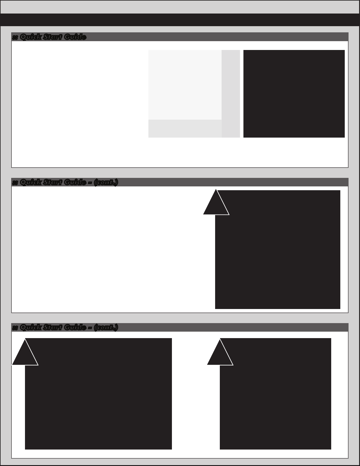
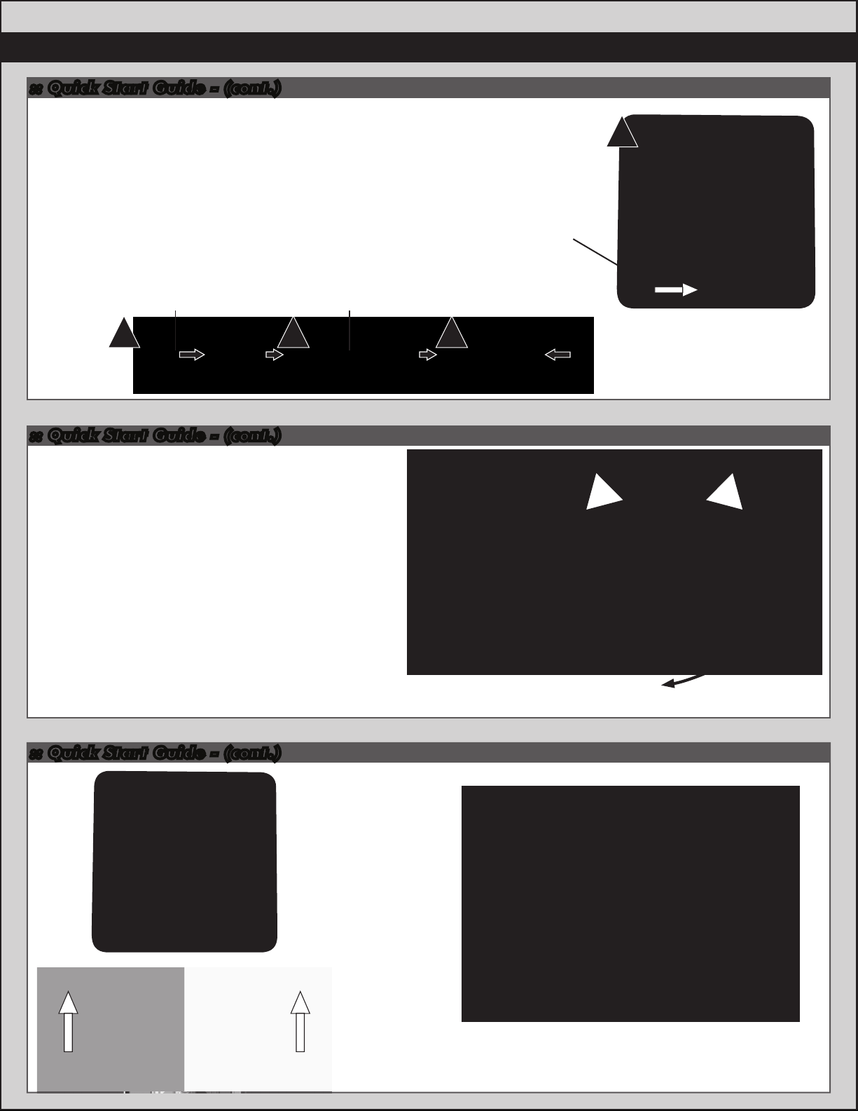
Battery Installation:
1. Install the batteries with the battery wires directed
towards the rear of the vehicle.
2. Insert the battery strap onto the battery post
screws.
3. Secure battery strap with thumb knobs.
Wall Charger Peak Detection
Quick Charger
1
:: Quick Start Guide - (cont.)
2 3
Page 6
6
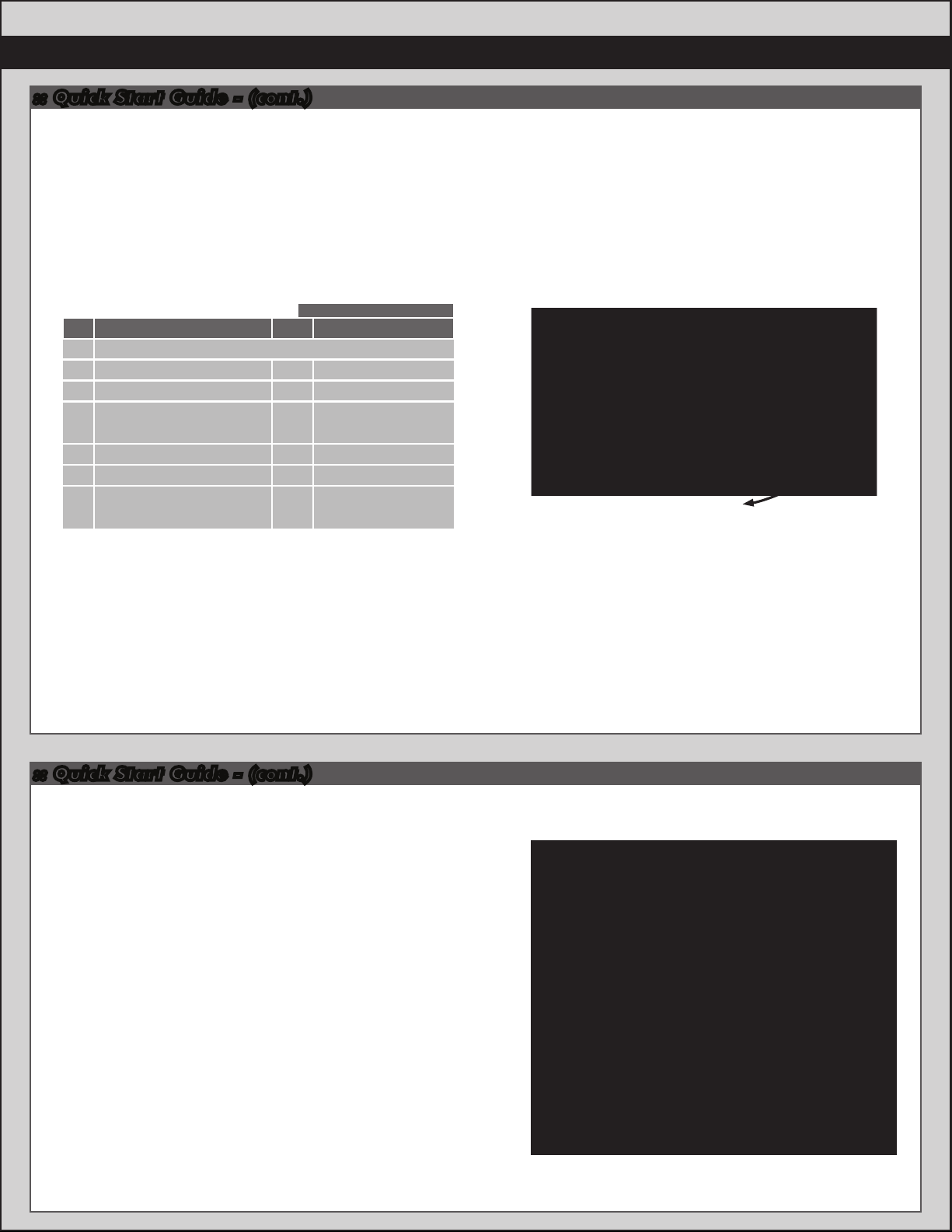
:: Quick Start Guide - (cont.)
Change the speed control to NiMH or LiPo battery
modes.
Battery Management System - A choice of either LiPo mode or NiMH
mode adjusts the low voltage cutoff point. This is critically important
when using LiPo batteries that should not, for performance and safety
reasons, be discharged below 3.0V per cell. In LiPo mode, the ESC
detects whether you are using 2 or 3 cells and adjusts the cutoff
accordingly.
The ESC can be toggled between LiPo mode and NiMH mode by
following the steps outlined below.
Signal From ESC
Step #
1
Trigger position to maximum brake (hold)
2
3
4
5
6
Procedure
Battery Management System
Power ON Transmitter
Power On ESC
Throttle position to neutral
Power OFF ESC, then transmitter
Power ON transmitter, then ESC
IMPORTANT! When the transmitter and ESC are turned on, the color
of the ESC LED at neutral indicates which mode the ESC is in. When the
LED is green, the ESC is in LiPo mode. When the LED is red, the ESC is
in NiMH mode.
Audio
bi-bi
2 green flash/ green static (LiPo Mode)
or red static (NiMH Mode)
melody
bibi-bibi
3 green flash, 2 red flash,
green static or red static
LED
Throttle set to Neutral when turning on the radio !
Pull for Throttle
Push for
Brake
Neutral
Vehicle Operation - To operate the vehicle, pull back on the throttle
trigger to move forward, push forward on the throttle trigger to
engage brakes. To engage reverse, push forward on the throttle
trigger to maximum brakes. Hold the trigger in this position for at
least 0.5 seconds before returning the throttle trigger to neutral.
Now push the throttle trigger forward to reverse the vehicle.
:: Quick Start Guide - (cont.)
Battery Notes and Tip:
Plug the batteries in as shown. Unplug batteries when not in use!
There are two types of batteries you can use with this vehicle.
NiMH (nickel-metal hydride) and LiPo (lithium polymer).
LiPo: LiPo batteries (lithium polymer) are high current
rechargeable batteries. LiPo batteries offer extended run time
and peak performance over NiMH batteries. They require a
peak detection charger designed specifically for LiPo batteries.
LiPo/LiFe Charger: (Part # 604 - Reedy 526-S AC/DC 2S-6S
Cell LiPo/LiFe Balance Charger)
These batteries require specal care and handling.
LiPo batteries are recommended for advanced users only!
ALWAYS charge a LiPo battery in LiPo mode.
CAUTION! If using a LiPo battery, you need to change the speed
control settings to LiPo mode (see instructions at top of page or
for complete speed control options and programming page 17
for detailed instructions).
Page 7
:: Quick Start Guide - (cont.)
Radio System Tuning and Controls:
7
RULE: Transmitter on First/Vehicle on Second.
When done driving: Vehicle off First/ Transmitter off Last!
1) Slide the battery cover in the direction shown to
remove cover.
2) Install eight (6) alkaline or rechargeable AA size
batteries into the battery holder.
3) Slide the battery cover back into place making
sure it is completely closed and secure.
4) Turn the power ON. If the power indicator LED
fails to light, check the batteries for insufficient
contact or incorrect polarity.
While pressing this part Battery cell (x6)
1 2 3
Battery cover
:: Quick Start Guide - (cont.)
Radio System Tuning and Controls:
DO NOT hold the trigger when turning on the radio.
If using optional battery for transmitter, be sure to plug
it in correctly. Plugging in a battery backwards can
cause damage.
4
On/Off Switch
RightLeft
Refer to Radio owners manual for more in-depth
instructions on radio operation and functions.
:: Quick Start Guide - (cont.)
Adjust steering
trim so front
wheels point
straight.
Push for
Brake
Pull for Throttle
Neutral
Throttle set to Neutral when turning on the radio !
Install body and body clips.
Ready to go!
Page 8
8
:: Wiring Diagrams
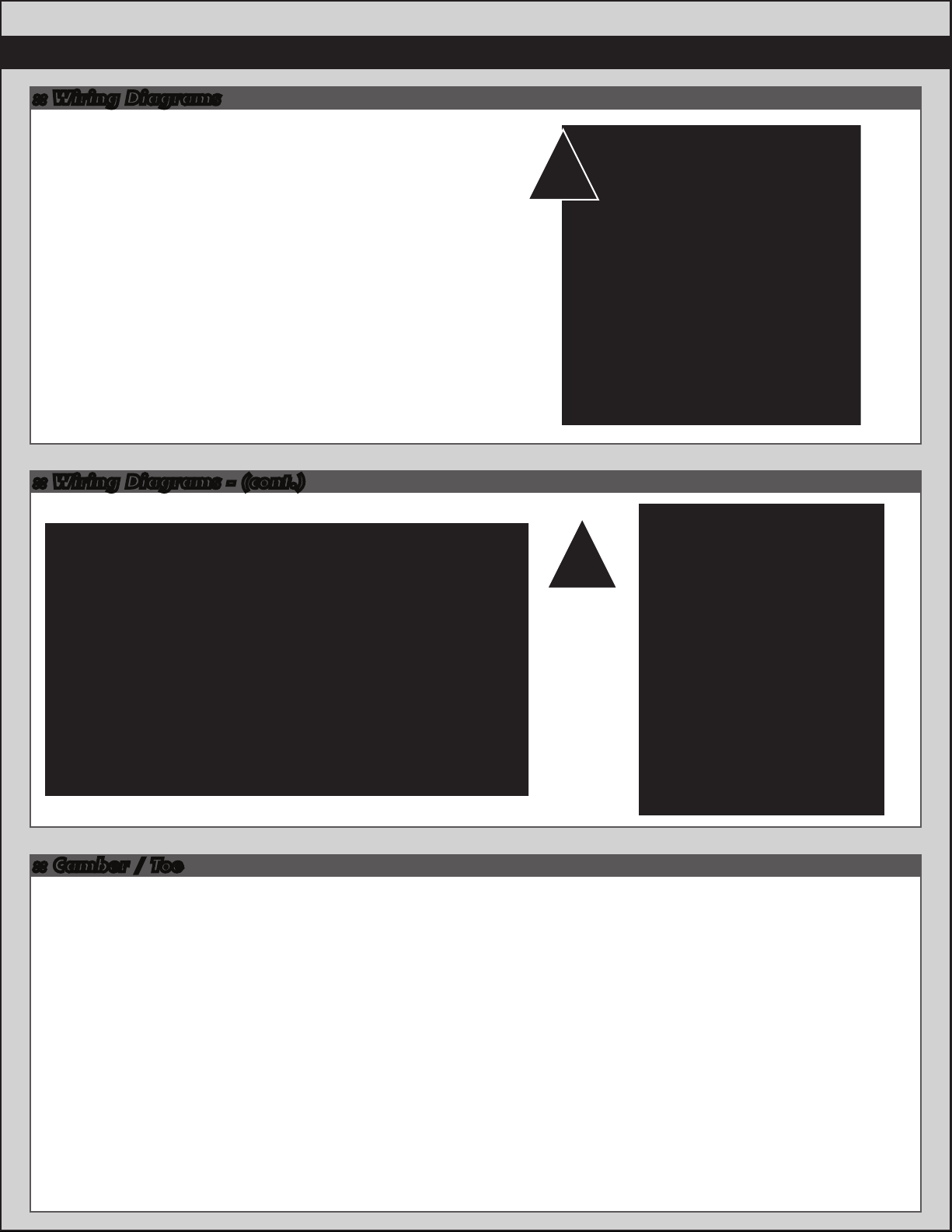
Motor and Receiver Wiring:
1. If motor runs in reverse when you apply throttle,
unplug any two of the motor wires and switch them.
2. Your Receiver has multiple channel ports for plugs.
Channel 1 - you should always plug your steering
servo into this channel port.
Channel 2 - you should always plug your speed
control (ESC) into this channel port.
Channel 3 - Used for optional equipment such as
fans, lights, ect...
Batt - Used for optional receiver battery pack.
Not used in this model.
Negative black wires on steering servo and speed control
plugs should face the outside edge of receiver where
channel markers are located.
:: Wiring Diagrams - (cont.)
1
2
:: Camber / Toe
Front Camber Angle:
A good starting camber setting is –2 degrees (where the top of the tires lean inwards). Positive camber, where the top
of the tire is leaning out, is typically not recommended.
Front Toe-In:
Zero degree toe-in (tires pointing straight forward) is a good starting setting. You can increase steering into corners
by adding 1-2 degrees of toe-out (front of tires point slightly outward). Toe - in is not a typical tuning adjustment used.
Rear Camber:
A good starting camber setting is –2 degrees. Use #1719 camber gauge (not included) to set your camber. Adding a
small amount of positive camber, where the top of the tire is leaning out, will tend to improve straight-line acceleration on
loose tracks.
Page 9
:: Gear Mesh
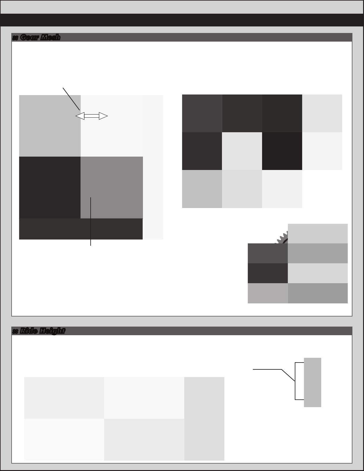
Gear Mesh:
To correctly set your gear mesh, follow the steps below:
1. Loosen the set screw on the motor’s pinion gear. Slide the pinion on the motor shaft until the gear face of the pinion
is entirely aligned with the gear face of the spur gear (see diagram). Tighten the set screw while ensuring it is aligned
with the flat face on the motor shaft.
Pinion
9
Spur Gear
2. Loosen the motor screws until the motor is able to move freely.
Slidethe motor as far as it can go towards the spur gear, ensuring that
the teeth of the pinion and the spur gear are interlocking. Slide the motor
back (approximately 0.5 mm), and tighten the motor screws.
Proper gear mesh has been achieved when the teeth are meshing closely,
but the gears still have a small amount of clearance between them. If you hold
one gear, you should be able to rock the other gear back and forth a small
amount. If there is no clearance, your gear mesh is too tight and you should
readjust the motor again.
:: Ride Height
Adjusting Ride Height:
The truck’s ride height can be increased by adding pre-load clips to the shocks.
Removing pre-load clips will decrease the ride height. Compress the spring and
insert the pre-load clips between the spring collar and the shock body flange.
Adding or removing ride height clips does not increase or decrease spring rate.
Pinion
7149
Shock
pre-load
clips
Spur Gear
1mm
2mm
4mm
6mm
Page 10

10
:: Spur Gear Access
:: Spur Gear Access - (cont.)
Spur Gear Maintenance:
When accessing your spur gear, check for wear on the
teeth of the gear. If teeth are deformed or sharp at the
peak, the spur gear should be replaced.
Also, check the slipper pads for wear.
Replace if necessary.
Slipper nut should be fully tightened!
Page 11

:: Center Diff Access
:: Center Diff Access - (cont.)
11
:: Center Diff Access - (cont.)
Stock Diff
Fluid Setting:
Center Diff:
Grease
Grease
Center Differential Maintenance:
Once you have removed the Center Diff gear, you can now
clean the existing diff grease from the dif ferential.
Check the diff gasket for wear or damage.
Replace if necessary
Fill the diff to the top of the cross pin with your choice of
diff fluids.
Suggested Diff Fluid Range: 100K to 500K
Thicker Diff Fluids:
Thicker fluids will get less low speed steering and better
acceleration out of turns.
Thinner Diff Fluids:
Thinner fluids will give more low speed traction.
Page 12

12
:: :: Front Diff Access
:: :: Front Diff Access - (cont.)
:: Front Diff Access - (cont.)
Page 13

:: Front Diff Access - (cont.)
!
Diff gear teeth
pointed towards
the right hand side
of the vehicle.
:: Rear Diff Access
13
:: Rear Diff Access - (cont.)
Page 14

14
:: Rear Diff Access - (cont.)
:: Rear Diff Access - (cont.)
!
Diff gear teeth
pointed towards
the left hand side
of the vehicle.
:: Front and Rear Diff Maintenance
Stock Shock
Fluid Setting:
Front:
grease
Rear:
grease
Grease
Differential Maintenance:
Once you have removed the Dif f gear, you can now clean
the existing diff fluid from the differential.
Check the diff gasket for wear or damage.
Replace if necessary
Fill the diff to the top of the cross pin with your choice of
diff fluids.
Front Diff: Suggested Diff Fluid Range: 10K to100K
Thicker oil will get less low speed steering and better
acceleration out of turns.
Rear Diff: Suggested Diff Fluid Range: 10K to100K
Thicker oil will rotate less in the turns and accelerate
straight on power. Thinner oil will give more low speed
traction.
Page 15

:: Shock Maintenance
:: Shock Maintenance - (cont.)
40wt
Shock fluid
Stock Shock
Fluid Setting:
Front: 40wt
Rear: 40wt
15
Bladder Installation
A B C
As you install the shock cap with the bladder, it will force
out any extra fluid. If you install the cap with the shaft
fully extended, you are running FULL REBOUND.This
means the shaft will fully rebound when compressed.
To run less rebound, unthread the cap 1-2 turns and
compress the shaft to the desired position and
re-tighten the cap with the shaf t compressed.
Start with no rebound.
:: Shock Maintenance - (cont.)
Step 5Step 3-4Step 1-2
Shock Maintenance:
If you need to only refill your shocks with oil, follow the steps
above only then move to the shock bleeding steps.
If your shocks leak from the bottom shock cap, follow all
shock maintenance sections.
Replace the inner O-Rings in the bottom cap, then begin
the shock oil filling and bleeding process.
Shock Bleeding Steps:
1. Pull shock shaft down.
2. Fill shock body 3/4 full with silicone
shock fluid.
3. Slowly move the shock shaf t up and
down to remove air from under the
piston.
4. Wait for bubbles to come to surface.
5. Fill shock body to top with silicone
shock fluid.
6. Place a drop of oil in the cap and on
cap threads.
7. Install cap and tighten completely.
8. Unscrew the cap 3/4 turns and tilt
the shock at a slight angle.
9. Slowly compress shaf t all the way to
bleed excess silicone shock fluid and
air. You should see bubbles coming
out from under the cap. (use rag
around shock to catch excess fluid).
10. With the shaft compressed, tighten
the cap and re-check for pressure at
the top of the stroke. If there is still
pressure, repeat steps 3-9.
Check for
pressure
Slow
Some residual
shock fluid may
appear from your
first few runs
around the shock
cap as a result of
bleeding.
Slow
Step 9-10Step 6-8
!
Page 16

16
:: Motor Manual
BRUSHLESS
Introduction
Congratulations on your purchase of the Reedy
1515-SL Brushless Motor. The latest brushless
motor technology along with the design and
engineering experience that is responsible for 28
World Championship titles has been incorporated
into its design.
Due to its sensorless design, the Reedy 1515-SL
Brushless Motor operates powerfully and efficiently
without complicated sensor harnesses. This motor
is perfectly suited for use with ESCs that are
designed to operate sensorless brushless motors.
Features
• Oversized Precision Ball Bearings
• High-Torque 4-Pole Rotor
• Hardened 5mm Steel Shaft
• Triple-Insulated Windings
• Sensorless Operation
• 4.0mm Connectors
Be sure to visit www.reedypower.com for the
latest application and gearing charts and to
view a complete list of spare and option parts.
Please read the following before
installing and using your new motor.
Precautions and Warnings
• Please read the instructions before installing
and operating your motor.
• Avoid over gearing by monitoring motor
temperature. Operating temperatures should
not exceed 80C (175F).
• Be sure to use the proper size motor mounting
screws.
• Do not over-tighten the motor mounting screws.
• Do not use a Schottky diode with this motor
Installation and Maintenance
• Your motor should be installed using 3mm
screws with a length (generally 10mm or less)
that does not allow the screw to extend into the
motor more than 5mm. Otherwise, the screw
can damage the motor’s internal components.
• Do not over-tighten the motor mounting screws.
Doing so may strip the mounting hole threads.
• Connect the three leads exiting the motor to the
three motor leads from your Electronic Speed
1515-SL
MOTOR
Control (ESC). If the motor runs backwards
when giving it forward throttle, reverse any two
motor leads. The motor will now turn in the
desired direction.
• To clean your motor, lightly brush dirt away on
a regular basis paying particularly close attention
to the areas around the ball bearings. DO NOT
spray cleaners or solvents into the motor.
Caution
When switching to a higher voltage battery from a
lower one (to 18.5V from 14.8V, for example), a
change in gear ratio or a lower kV motor might be
necessary. Otherwise, the motor or ESC may
overheat and sustain permanent damage. Please
visit www.reedypower.com for the latest gear ratio
suggestions for your particular motor and vehicle.
Safety Precautions
This product is a sophisticated hobby product and
not a toy. It must be operated with caution and
common sense and requires some basic
mechanical ability. Failure to operate this product
in a safe and responsible manner could result in
injury or damage to the product or property. This
product is not intended to be used by children
without direct adult supervision. It is essential to
read and follow all instructions and warning found
in this manual prior to installation, set up, and use
in order for the product to operate properly and to
avoid damage or injury.
Specifications
Model
Item No.
Cells
RPM/Volt
Diameter
Length
Weight
Shaft Diameter
Max. Efficiency Current
Max. Surge Current
Internal Resistance
1515-SL 2000kV
929
3S-4S LiPo
2000
40mm
74mm
380g/13.4oz
5.0mm
20~50A
100A/15s
Warranty
Your motor is warranted to the original purchaser
for 30 days from the date of purchase against
defects in material and workmanship. Motors that
have been mishandled, abused, used incorrectly,
used for an application other than intended or
damaged by the user are not covered under
warranty.
Associated Electrics Inc. is not liable for any loss or
damage, whether direct or indirect, incidental or
consequential, or from any special situation, arising
from the use, misuse, or abuse of this product.
Page 17

:: ESC Manual
#29146
XP SC1300-DB
17
Brushless ESC
Introduction
Congratulations on your XP Brushless Electronic Speed Control (ESC)
purchase. The latest electronics technology along with the design and
engineering experience that is responsible for multiple World
Championship titles has been incorporated into its design.
Your XP Brushless ESC is water-resistant for maximum durability. Its light
and compact design allows for easy installation in most 1/8 vehicles. Dual
connectors allow plug and play use in vehicles that require two batteries.
Simple calibration and a wide variety of tuning options make this ESC
perfect for both casual enthusiast and racers. When paired with a Reedy
Brushless Motors, you create a potent combination of power and efficiency
that brings performance to a new level. More power and less maintenance
elevate the fun factor by increasing top speeds and reducing down time.
Please read the following before installing and operating
your new ESC.
Features
• Adjustable LiPo Low-Voltage Cutoff
• LiPo Cell Count Auto Detect
• Reversible With Reverse Lockout
• Fully Proportional Brakes
• Adjustable Drag Brakes
• Adjustable Throttle Profile
• Hard Case with Aluminum Heat Sink
• Water Resistant
• Heavy Duty Silicone Wires
• Dual Deans® Ultra Plug® Connector
• 4.0mm Motor Connectors
• Pre-Wired For Optional Cooling Fan
Safety Precautions
This product is a sophisticated hobby product and not a toy. It must be
operated with caution and common sense and requires some basic
mechanical ability. Failure to operate this product in a safe and responsible
manner could result in injury or damage to the product or property.
This product is not intended to be used by children without direct adult
supervision. It is essential to read and follow all instructions and warnings
found in this manual prior to installation, set up, and use, in order for the
product to operate properly and to avoid damage or injury.
Throttle Calibration
Your new ESC must be calibrated before use. Before calibration, be sure to
set your radio’s throttle and brake EPAs to 100% and your throttle trim to
neutral. Then follow the steps outlined below.
Procedure
Step #
Power ON transmitter
1
Throttle position to maximum throttle (hold)
2
Power ON ESC
3
Throttle trigger position to neutral
4
Throttle trigger position to maximum brake
5
Throttle trigger position to neutral
6
Power OFF ESC, then transmitter
7
Once the calibration procedure is complete, turn on your transmitter, then
your ESC, and begin operating your vehicle. Note: If you choose to make
settings adjustments at this time, you can do so immediately after step #6
of the throttle calibration procedure.
Audio
bibibibibibi
bibi-bibi
bibi-bibi
Signal From ESC
LED
red static/6 green flash
red static/4 green flash
red static /4 green flash
red static
Step #
1
Throttle trigger position to maximum to select value
2
Throttle trigger position to maximum to select value
3
Throttle trigger position to maximum to select value
4
5
Procedure
Drag Brakes
0% (default)
2.5%
5%
10%
Throttle position to neutral
Throttle Profile
Very Soft
Soft
Standard (default)
Maximum
Throttle position to neutral
Run Mode
Reverse Off (Forward Only)
2-Stage Reverse (default)
Throttle position to neutral
Power OFF ESC and transmitter
Power ON transmitter and ESC
Signal From ESC
LED
red static/green flashes
red static/4 green flash
red static
red static/green flashes
red static/4 green flash
red static
red static/green flashes
red static/4 green flash
3 green flash, 2 red flash
green static or red static
Specifications
Description
Cells
On Resistance
Brakes
Motor Limit
Reversible
Low Voltage Cutoff
Dimensions
Weight w/Wires
Power Wires
Connector Type
Installation
• Mount your ESC securely using high quality double-sided tape.
• Install your ESC in a position that allows easy access to all connectors.
• Plug the ESC’s receiver wire into the receiver
(refer to radio manufacturer’s manual)
• To prevent radio interference, arrange ESC wiring so that it is not in close
proximity to the receiver antenna wire.
• Connect the three motor leads exiting the ESC to the three leads exiting
your motor. If the motor runs backwards when giving it forward throttle,
reverse any two motor leads. The motor will now run the desired direction.
• Mount the switch to the case using the tab provided.
• Always power ON your transmitter before the ESC, and power OFF the
ESC before the transmitter.
Programmable Settings
Your ESC comes with pre-programmed default settings. You can also
change the setting based on the type of vehicle used as well as personal
performance preferences based on the track you are driving on and your
driving style.
Drag Brake - Drag brake is the amount of braking achieved when the
throttle is returned to neutral. A setting of 0% means the vehicle will free
wheel to a stop while higher settings will stop the car faster. Please note
that regardless of the drag brake setting, you will still be able to use the
brake trigger to manually slow the car.
Throttle Profile – This setting adjusts the power delivery of your
ESC/motor combination. The Very Soft setting can be used on loose or
bumpy track to reduce wheel spin while the Maximum setting works well
when high traction is available. Four settings provide options for any track
condition.
Run Mode - This gives the option of using reverse or eliminating it
completely (for competition). With reverse activated, you will still have fully
proportional braking.
To make settings adjustments, you must first follow the calibration
procedure. After step #6, you will encounter a 5-second delay before
entering the settings adjustment mode. All changes will be made using
your transmitter’s throttle trigger. Note: Once you enter the settings
adjustment mode, the ESC will scroll through all options. If you fail to
choose a setting, the ESC will keep the previously saved setting.
For example, if you want to change the throttle profile from Soft to
Standard, enter the settings mode. You will encounter the Drag Brake
mode first at which time you can let the ESC scroll through the choices
(the previously saved setting will be kept) until you reach the Throttle
Profile choices. You must make the selection by pulling the throttle trigger
to maximum after the ESC scrolls to the desired setting (in this case
Standard) indicated by the appropriate audible tones. Once this setting
(or any setting for that matter) is chosen, you can skip to Step #5 if no
other changes are desired.
Battery Management System
Battery Management System - A choice of either LiPo mode or NiMH mode
adjusts the low voltage cutoff point. This is critically important when using
LiPo batteries that should not, for performance and safety reasons, be
discharged below 3.0V per cell. In LiPo mode, the ESC detects whether you
are using 2 or 3 cells and adjusts the cutoff accordingly.
The ESC can be toggled between LiPo and NiMH by following the steps
outlined below. The default setting is NiMH mode.
Procedure
Step #
Battery Management System
Power ON transmitter
1
Throttle position to maximum brake (hold)
2
Power ON ESC
3
Throttle trigger position to neutral
4
Power OFF ESC, then transmitter
5
Power ON transmitter, the ESC
6
IMPORTANT! When the transmitter and ESC are turned on, the color of the
ESC LED at neutral indicates which mode the ESC is in. When the LED is
green, the ESC is in LiPo mode (3.2V/cell cut off). When the LED is red, the
ESC is in NiMH mode (default).
Vehicle Operation - To operate the vehicle, pull back on the throttle trigger
to move forward and push forward on the throttle trigger to engage brakes.
To engage reverse, push forward on the throttle trigger to maximum brakes.
Hold the trigger in this position for at least .5 seconds before returning the
throttle trigger to neutral. Now push the throttle trigger forward to reverse the
vehicle.
Signal From ESC
Audio
bi-bi
melody
bibi-bibi
LED
2 green flash
green static (LiPo) or
red static (NiMH)
3 green flash, 2 red flash
green static or red static
Page 18

18
:: Shocks :: Drive Shafts
25058
25059
25061
25062
25063
25064
25065
25069
25070
Assembled Shocks, Set of eight
Assembled Shocks, Set of two
Shock Rebuild & Shafts, Set
Blue/Soft Shock Springs, 4.40 lbs
Gold/Medium Shock Springs, 5.10 lbs
Red/Firm Shock Springs, 5.95 lbs
Copper/Extra Firm Shock Springs, 6.90 lbs
Shock Eyelets & Accessories, Set
Shock Mounting Hardware, Set
8
25689
2
25747
1
25748
4
4
4
4
1
1
Center CVA Rebuild Kit
RIVAL-MT Center Drive Shaft, Front
RIVAL-MT Center Drive Shaft, Rear
25689
25689
1
1
1
25689
25689
25059
25061
25059
25061
25061
25061
25061
25059
25059
25059
25061
25059
25061
25061
25069
25069
25062
25069
:: Steering
25125
25126
25127
25180
25215
Bellcrank Plastic Parts Set
Bellcrank Posts (2) & Bushings (4)
Bellcrank Hardware
M3 x 8mm BHPS
M3 Locknut
25689
25747
25748
25689
25689
25689
25126
25689
25689
25689
25748
25689
25180
25747
25689
25748
25689
1
1
1
20
20
:: Shock Fluid
5420
5421
5422
5423
5424
5425
5426
5427
5428
5429
5430
5431
5432
5433
5434
5435
5436
5437
5438
10 Weight Silicone Shock Fluid
20 Weight Silicone Shock Fluid
30 Weight Silicone Shock Fluid
40 Weight Silicone Shock Fluid
22.5 Weight Silicone Shock Fluid
80 Weight Silicone Shock Fluid
27.5 Weight Silicone Shock Fluid
15 Weight Silicone Shock Fluid
25 Weight Silicone Shock Fluid
35 Weight Silicone Shock Fluid
45 Weight Silicone Shock Fluid
55 Weight Silicone Shock Fluid
32.5 Weight Silicone Shock Fluid
37.5 Weight Silicone Shock Fluid
42.5 Weight Silicone Shock Fluid
50 Weight Silicone Shock Fluid
60 Weight Silicone Shock Fluid
70 Weight Silicone Shock Fluid
47.5 Weight Silicone Shock Fluid
2oz.
2oz.
2oz.
2oz.
2oz.
2oz.
2oz.
2oz.
2oz.
2oz.
2oz.
2oz.
2oz.
2oz.
2oz.
2oz.
2oz.
2oz.
2oz.
25215
25125
25127
25127
25127
25125
25127
25215
25127
25127
25126
25215
25125
25127
25126
25127
25215
25180
25126
25126
25125
25126
Page 19

:: Radio Tray and Servo Saver
6338
25162
25166
25167
25181
25207
25215
25225
25232
25613
25751
89208
Antenna Tube with Cap, black
Servo Saver, XT/Futaba - (Used in RTR)
Servo Saver, Hitec
Servo Saver, JR/Airtronics
M3 x 10mm BHPS
M3 x 10mm BHPTS
M3 Locknut
M3 x 3mm Set Screw
Lock Washer
M3 x 6mm BHPS
RIVAL-MT Receiver Tray
M3 x 14mm FHCS
1
1
1
1
20
20
20
20
20
20
1
10
25751
25751
25181
25181
19
25181
25225
6338
25162
25162
25162
25162
25162
25162
25232
25162
:: Battery Tray / Strap and Roll Bar
3848
4689
7732
25181
25185
25215
25613
25620
25749
25757
Foam Battery Spacer
(Use with LiPo Batteries - Not pictured)
M3 x 16mm Set Screw
4mm x 4mm Set Screw
M3 x 10mm BHPS
M3 x 20mm BHPS
M3 Locknut
M3 x 6mm BHPS
M3 x 10mm SHCS
RIVAL-MT Battery Tray
RIVAL-MT Roll Hoop
1
6
6
20
20
20
20
20
1
1
25215
89208
25215
89208
25207
89208
25207
25215
25751
89208
7732
6338
25751
25613
25757
7732
25757
25185
25749
25185
25749
25749
4689
25749
25749
4689
25215
25181
25181
25613
25757
25749
25613
25613
25620
25613
25620
Page 20

20
2
:: Front Bumper
7164
25183
25184
25203
25208
25763
Washer, 3 x 6 x 0.5mm
M3 x 14mm BHPS
M3 x 16mm BHPS
M3 x 12mm FHCS
M3 x 22mm BHPS
RIVAL-MT Front Bumper
10
20
20
20
20
1
25763
25184
7164
25184
7164
:: Rear Bumper
7164
25182
25184
25203
25208
25764
Washer, 3 x 6 x 0.5mm
M3 x 12mm BHPS
M3 x 16mm BHPS
M3 x 12mm FHCS
M3 x 22mm BHPS
RIVAL-MT Rear Bumper
10
20
20
20
20
1
25183
25208
25208
25184
7164
25764
25183
7164
25764
25763
25763
25763
25203
25184
25764
25182
25208
25182
:: Front and Rear Gear Differential
25081
25085
25204
25236
25715
Assembled Differential
Differential Outdrives & Gaskets
M3 x 16mm FHCS
Bearing, 8 x 16 x 5
Differential Shims
1
1
20
2
10
25204
25764
25085
25236
25203
25081
25085
25208
25081
25085
25715
25236
25081
25081
25715
Page 21

:: Transmission Internal Gears
O-Rings
25236
25238
25741
25742
25743
25744
25745
Bearing, 8 x 16 x 5
Bearing, 6 x 12 x 4
RIVAL-MT Gear Set
RIVAL-MT Center Diff Assembly
RIVAL-MT Center Diff Rebuild
RIVAL-MT Center Diff O-Rings
RIVAL-MT Center Diff Outdrives
2
2
1
1
1
2
1ea
25741
25741
25741
25741
25238
25238
25741
25743
25743
25238
25741
25743
21
25742
25238
2574525741
25236
25742
25744
25742
:: Transmission
25180
25181
25199
25212
25223
25238
25613
25620
25739
25740
89218
89512
89513
89514
89515
89516
89517
89593
89594
89595
89596
M3 x 8mm BHPS
M3 x 10mm BHPS
M3 x 8mm FHPS
M3 x 12 FHPS
M4 x 3mm Set Screw
Bearing, 6 x 12 x 4
M3 x 6mm BHPS
M3 x 10mm SHCS
RIVAL-MT Tranny Case
RIVAL-MT Motor Plate
3 X 8mm Washer
12T Pinion
13T Pinion
14T Pinion
15T Pinion - Kit
16T Pinion
17T Pinion
18T Pinion
19T Pinion
20T Pinion
21T Pinion
25236
25745
20
20
20
20
20
2
20
20
1
1
10
1
1
1
1
1
1
1
1
1
1
25744
25238
25743
25743
25742
25744
25212
25223
25743
25740
25743
25743
25180
25743
25212
25739
25739
25212
25613
25739
25739
25613
25739
25181
89515
25620
89218
25180
25199
Page 22

22
:: Front Gearbox
25051
25056
25080
25082
25106
25125
25128
25184
25190
25191
25199
25201
25202
25203
25208
25209
25215
25236
Front / Rear Drive Input Cup w/ Set Screws
Drive Cup Set Screws
Differential Pinion Gear & Shaft
Front/Rear Transmission Case with screws
Front & Rear Transmission Chassis Mounts
Bellcrank Plastic Parts
Front Skid Plate
M3 x 16mm BHPS
M3 x 14mm SHCS
M3 x 18mm SHCS
M3 x 8mm FHPS
M3 x 8mm FHCS
M3 x 10mm FHCS
M3 x 12mm FHCS
M3 x 23mm BHPS
M3 x 32mm BHPS
M3 Locknut
Bearing, 8 x 16 x 5
1
4
1
1
1
1
1
20
20
20
20
20
20
20
20
20
20
2
25190
25208
25209
25191
25106
25082
25208
25208
25080
25082
25236
25184
25082
25051
25056
25215
25190
25191
25106
:: Front Suspension
25107
25109
25110
25112
25113
25116
25184
25215
25225
25238
25654
25698
25768
25769
89218
89405
Upper Suspension Arm
Lower Suspension Arm
Upper & Lower Arm Hinge Pins
Steering Block/Hub Carrier
Pivot Balls
Axle Bearing Spacers
M3 x 16mm BHPS
M3 Locknut
3mm x 3mm Allen Set Screw
Bearing, 6 x 12 x 4
M3 x 18 BHPS
Universal Rebuild Kit
RIVAL-MT CVA
RIVAL-MT Wheel Hexes
3 X 8mm Washer
Nyloc Wheel Nuts, silver
Pr.
20
20
20
20
10
25125
25215
25128
25199
25203
25202
2
2
8
4
4
2
1
2
4
4
25110
25107
25201
25113
25110
25768
25184
25184
25698
25109
25698
25768
25698
25116
25112
25113
89218
25654
25238
25215
25769
25225
25112
25238
25769
89405
Page 23

:: Rear Gearbox
25769
25051
25056
25080
25082
25106
25134
25184
25191
25199
25202
25208
25209
25215
25236
89218
Front / Rear Drive Input Cup w/ Set Screws
Drive Cup Set Screws
Differential Pinion Gear & Shaft
Front/Rear Transmission Case with screws
Front & Rear Transmission Chassis Mounts
Rear Skid Plate
M3 x 16mm BHPS
M3 x 18mm SHCS
M3 x 8mm FHPS
M3 x 10mm FHCS
M3 x 23mm BHPS
M3 x 32mm BHPS
M3 Locknut
Bearing, 8 x 16 x 5
3 X 8mm Washer
1
4
1
1
1
1
20
20
20
20
20
20
20
2
10
25191
25184
25051
25056
25208
25082
25236
25080
25082
25215
25082
23
25191
25106
25215
89218
25184
:: Rear Suspension
25107
25109
25110
25112
25113
25116
25184
25215
25225
25238
25654
25698
25768
25769
89218
89405
Upper Suspension Arm
Lower Suspension Arm
Upper & Lower Arm Hinge Pins
Steering Block/Hub Carrier
Pivot Balls
Axle Bearing Spacers
M3 x 16mm BHPS
M3 Locknut
3mm x 3mm Allen Set Screw
Bearing, 6 x 12 x 4
M3 x 18 BHPS
Universal Rebuild Kit
RIVAL-MT CVA
RIVAL-MT Wheel Hexes
3 X 8mm Washer
Nyloc Wheel Nuts, silver
Pr.
20
20
20
20
10
89218
25106
25208
25209
25184
25134
25199
25202
2
2
8
4
4
25107
2
1
2
4
4
25113
25110
25238
25769
25225
89405
25112
25769
25238
25116
25112
25112
89218
25698
25768
25215
25654
25698
25113
25698
25109
25768
25184
25110
25184
Page 24

24
:: Front Bumper and Chassis
25102
25105
25181
25201
25207
25215
25753
Chassis Guards (L&R) and End Covers (2)
Front & Rear Upper Arm Mounts
M3 x 10mm BHPS
M3 x 8mm FHCS
M3 x 10mm BHPTS
M3 Locknut
RIVAL-MT Chassis
1
2
20
20
20
20
1
25181
25201
25105
25207
25102
25105
25207
25181
25105
25181
25215
25105
25215
25215
25181
25181
25215
25753
25102
25215
25105
25201
25181
25215
25105
25102
25207
25102
25207
25105
25105
25201
25201
25215
25215
Page 25

:: Front and Rear Shock Towers
2208
25070
25135
25136
25137
25188
25189
25205
Large Hood Pins
Shock Mounting Hardware
Front Shock Tower
Rear Shock Tower
Pivoting Body Mounts (2) & Posts (4)
M3 x 20mm BHCS
M3 x 22mm BHCS
Body Post Mounting Screws
6
1
1
1
1
20
20
20
25205
25137
2208
25137
25
2208
:: Turnbuckles
25754
25756
RIVAL-MT Turnbuckle Set
(8 Ball Joints & eyelets, 2 104mm TB, 2 118mm TB)
RIVAL-MT Turnbuckle Eyelets
(8 Ball Joints & eyelets)
25756
25188
25189
25188
25189
25205
25070
Front - 25135
Rear - 25136
25070
25070
:: Lubes & Adhesives / Decals / Misc.
1
1105
1596
1
1597
5450
5451
5452
5453
5454
5455
5456
5457
5458
5459
6588
6591
6636
6727
FT Green Slime Shock Lube
FT Locking Adhesive
FT Tire Adhesive, Medium
Silicone Diff Fluid 1000cst
Silicone Diff Fluid 2000cst
Silicone Diff Fluid 3000cst
Silicone Diff Fluid 5000cst
Silicone Diff Fluid 7000cst
Silicone Diff Fluid 10000cst
Silicone Diff Fluid 20000cst
Silicone Diff Fluid 30000cst
Silicone Diff Fluid 60000cst
Silicone Diff Fluid 100000cst
Black Grease - 4cc
S.Diff Lube - 4cc
Silicone Grease - 4cc
Servo Tape
25205
25137
25070
25070
25070
25205
1
1
1
1
1
1
1
1
1
1
1
1
1
1
1
1
2
25756
25754
25756
716
3816
3820
3834
Reedy 2009 Sticker Set
American Bumper Sticker
AE Logo Decal Sheet
AE Blue Embossed Logo Sticker
1
1
1
2
1596
Page 26

26
6
:: Slipper, Spur Gear, Pinion, and Drive Shaft
25677
25678
25679
25680
25681
25746
31541
Slipper Hardware
Spur Gear Hub
Slipper Friction Ring
Slipper Pad
Slipper Hub
RIVAL-MT Spur Gear (56T) - Kit
M3 x 0.5 x 6 FHCS
1
1
1
2
1
1
6
:: Wheels / Tires
25766
25767
25770
RIVAL-MT Tire & Insert
RIVAL-MT Beadlock Wheel
RIVAL-MT Wheel/Tire Pre-Mounted
25677
25677
2
2
2
25746
25677
31541
25681
25680
25679
25678
25766
25766
25767
25767
25767
25767
Page 27

27
:: Body / Decals
25758
25759
25765
Rival MT Body - Painted
Rival MT Body - Clear
Rival MT Decal Sheet
:: Factory Team and Option Parts
25062
25063
25064
25065
25139
25140
25381
25382
25383
25390
25391
25392
25395
25396
25397
25398
25403
25404
25725
25726
25727
25728
MGT Blue Spring, Soft [4.40lb]
MGT Gold Spring, Medium [5.10lb]
MGT Red Spring, Firm [5.95lb]
MGT Copper Spring, Extra Firm [6.90lb]
Rear Clip and Flag Mount
Rear AE Flag and Post
FT Blue Steering Turnbuckle, Titanium
FT Blue Rear Turnbuckle, Titanium
FT Monster GT Turnbuckle Set, Titanium
5mm Blue Aluminum Locknut
4mm Blue Aluminum Locknut
3mm Blue Aluminum Locknut
MGT Aluminum Steering Kit
MGT Aluminum Steering Rack and Arm
MGT Aluminum Servo Saver Hub and Spring
MGT Aluminum Steering Hardware Set
MGT Blue Aluminum Shock Bodies
MGT Blue Aluminum Shock Caps w/ Bladders
FT Steering Bushing
FT Shock Bottoms
FT Aluminum Shock Set, Builds 2 Shocks
FT Blue Wheel Hex
:: Reedy Accessories / Motor
1
1
1
4
4
4
4
1
1
1
1
1
10
10
10
1
1
1
1
4
4
4
4
1
4
604
609
610
654
655
656
658
659
716
929
:: Reedy Batteries
302
303
724
725
730
731
732
734
:: Qualifier Series Vehicles
7052
20510
30112
526-S AC/DC 2S-6S LiPo/LiFe Charger
TAM to DEANS® charge adapter
447-S AC/DC NiMH Peak Charger
4.0mm plugs (2M, 2F)
4.0mm plugs (2M, 10F)
4.0mm plugs (10F)
4.0mm plugs (10M)
4.0mm plugs (30M)
Reedy 09 Decal Set
1515-SL Brushless Motor 2000kV
AA Alkaline 1.5V (4)
AA 2700mAh NiMH 1.2V Rechargeable (4)
Wolfpack 3000mAh 8.4V w/DEANS® connector
Wolfpack 3600mAh 8.4V w/DEANS® connector
Wolfpack LiPo 3000mAh 7.4V 25C w/DEANS®
Wolfpack LiPo 3300mAh 7.4V 35C w/DEANS®
Wolfpack LiPo 3400mAh 7.4V 35C w/DEANS®
Wolfpack LiPo 6500mAh 7.4V 25C w/DEANS®
Pro Lite 4x4 RTR, 1/10 Scale (ready-to-run)
RIVAL Electric Monster Truck RTR, 1/8 Scale
(ready-to-run)
APEX Touring V-Type, 1/10 Scale (ready-to-run)
1
1
1
1
1
1
1
1
1
1
1
1
1
1
1
1
1
1
1
1
1
:: XP Electronics
29142
29146
29166
29167
29168
29209
29210
29211
29212
29214
29215
29216
XP ESC Fan Option
XP SC1300-DB Brushless Dual-Battery ESC
XP DS1313 Digital Servo
XP DS1015 Digital Servo
XP DS1510MG Digital Servo
Gear Set, DS1313
Gear Set, DS1015
Servo Case , DS1313/DS1015
Accessory Pack, DS1313/DS1015
TRS403-SSi 2.4GHz 4Ch Receiver
XP2G 2.4GHz Radio System
XP3G 2.4GHz Radio System
:: LRP Chargers, Power Supply, Balancer
LRP41281
LRP41555
LRP42103
LRP42104
LRP42105
LRP42305
LRP42306
LRP43200
LRP45050
LRP45200
LRP65800
LRP65802
LRP65803
LRP65804
LRP81801
Quadra Pro 2 Charger
Pulsar Touch Competition Charger
LiPo Balance Board XH
LiPo Balance Board FP/TP
LiPo Balance Board PQ
Pulsar Touch Temperature Sensor
Pulsar Touch Sensor Wire Splitter
LRP Competition 20A Power Supply
LRP 2in1 LiPo Guard + BEC
LiPo Parallel Balancer
High Power Solder Station
Soldering Tip 5mm
Soldering Tip 1.2mm
Soldering Handle
LRP Speedo Updater Spec 2
:: 1/18 Kits and RTR’s
20103
20121
1
1
:: 1/12, 1/10 Kits and RTR’s
1
1
2042
1
4020
1
7025
1
7029
1
7030
1
7037
1
7038
1
7046
1
7047
7048
7049
7050
7092
7093
1
8020
1
8022
1
9039
1
9040
1
9041
1
9050
1
9062
1
30101
1
30108
1
90004
1
90005
1
90006
1
90007
1
90010
1
RC18B2 - RC18T2 Team Kit
SC18 RTR Brushless (ready-to-run)
Nitro TC3 RTR Plus (ready-to-run)
FT 12R5.2 Kit
RC10T4.2 FT Kit
SC10 Associated/RC10.com Truck RTR (ready-to-run)
SC10 KMC Wheels Race Truck RTR (ready-to-run)
RC10T4.1 RTR 2.4GHz Brushless (ready-to-run)
SC10.2 FT Kit
SC10 RS RTR, Lucas Oil (ready-to-run)
SC10 RS RTR, Monster Energy (ready-to-run)
SC10 RS RTR, Pro Comp (ready-to-run)
SC10 RS RTR, Rockstar/Makita (ready-to-run)
SC10 RS RTR, Hart and Huntington (ready-to-run)
GT2 RS Truck Nitro RTR (ready-to-run)
SC10GT RTR (ready-to-run)
FT RC10R5 Kit
FT RC10R5.1 Kit
RC10B4.1 RTR 2.4GHz Brushless (ready-to-run)
FT RC10B4.1 Worlds Kit
FT RC10B4.2 Kit
SC10B RS RTR (ready-to-run)
FT B44.2 4WD Buggy Kit
TC4 Club Racer 4WD Touring Car Race Roller
FT TC6.1 WC 4WD Touring Car Kit
SC10 4x4 Kit
SC10 4x4 Lucas Oil RTR (ready-to-run)
SC10 4x4 Pro Comp RTR (ready-to-run)
SC10 4x4 Rockstar/Makita RTR (ready-to-run)
SC10 4x4 FT Kit
1
1
1
1
1
1
1
1
1
1
1
1
1
1
1
1
1
1
1
1
1
1
1
1
1
1
1
1
1
1
Page 28

:: Hardware - 1:1 Scale View
28
Cap Head (shcs)
3x12mm w/hole (31427)
Shims and Washers
Nylon Washer .030 (4187)
3x6mm Washer (7164)
3x8mm Thin Washer
4mm Hex Drive Washer
6x12mm Washer (7165)
3x10mm (25620)
3x14mm (25190)
3x18mm (25191)
4x12mm (31426)
(89218)
(31428)
4mm Lock Washer
(31429)
Flat Head (fhcs)
2.5x6mm (4675)
2.5x8mm (31448)
2.5x10mm (31350)
3x6mm (31541)
3x8mm (25201)
3x8mm FHPS (25199)
3x10mm (25202)
3x12mm (25203)
3x14mm (89208)
3x16mm (25204)
3x18mm (89209)
3x22mm (89455)
Button Head (bhcs)
2.5x6mm (31520)
3x4mm(91158)
3x6mm (31531)
3x6mm BHPS (25613)
3x8mm (31532)
3x8mm BHPS (25180)
3x10mm (25211)
3x10mm BHPS (25181)
3x10mm BHPTS (25207)
3x12mm (89202)
3x12mm BHPS (25182)
3x14mm (25187)
3x14mm BHPS (25183)
3x16mm (89203)
3x16mm BHPS (25184)
3x18mm (2308)
3x18mm BHPS (25654)
Setscrew
3x3mm (25225)
3x16mm (4689)
4x3mm (25223)
4x4mm (7732)
4x10mm (31449)
Nuts (lock/plain)
M3 Locknut (25215)
M3 Alum. Locknut, Blue (31550)
M4 Locknut w/Flange & Knurl (91148)
FT M4 Locknuts w/Flange,
Blue (31551)
Ball Bearings
6x12x4mm (25238)
8x16x5mm (25236)
3x20mm (25188)
3x20mm BHPS (25185)
3x22mm (25189)
3x22mm BHPS (25208)
3x24mm (89204)
3x26mm (89205)
3x32mm BHPS (25209)
Page 29

29
:: 1/8 Kits and RTR’s
20501
20502
20503
20504
80905
80906
80907
80908
80912
80933
80934
MGT 4.60 SE RTR (ready-to-run)
MGT 8.0 Nitro RTR (ready-to-run)
Limited Edition MGT 4.60 Nitro RTR, w/flag body
(ready-to-run)
Limited Edition MGT 8.0 Nitro RTR, w/flag body
(ready-to-run)
RC8RS “Race Spec” Nitro Buggy RTR (ready-to-run)
RC8.2 Nitro Buggy FT Kit
RC8.2e Electric Buggy FT Kit
RC8.2e Electric Buggy RTR (ready-to-run)
RC8T Championship Edition
SC8.2e Short Course Race Truck, Rockstar/Makita
Electric RTR (ready-to-run)
SC8.2e Short Course Race Truck, Slick Mist Electric
RTR (ready-to-run)
:: Tools
1449
1541
1542
1543
1544
1545
1546
1547
1548
1551
1553
1554
1561
1562
1563
1564
1565
1567
1589
1590
1592
1655
1656
1657
1658
1659
1660
1661
1662
1663
1664
1665
1666
1667
1668
1669
1670
1671
1672
1673
1674
1719
1737
3718
3719
3720
6429
7709
89240
FT Off Road Ride Height Gauge
FT Hex Driver Set, (7 pcs)
FT .050” Silver Hex Driver
FT 1/16” Black Hex Driver
FT 1.5mm Purple Hex Driver
FT 5/64” Blue Hex Driver
FT 3/32” Gold Hex Driver
FT 2.5mm Green Hex Driver
FT 3mm Red Hex Driver
FT Screwdriver Set
FT Phillips Silver Screwdriver
FT Silver Spring Hook Tool
FT Nut Driver Set, (6 pcs)
FT 3/16” Black Nut Driver
FT 1/4” Red Nut Driver
FT 5.5mm Red Nut Driver
FT 11/32” Green Nut Driver
FT 8mm Gold Nut Driver
FT 5/64” Blue Ball Hex Driver
FT 3/32” Gold Ball Hex Driver
FT Ball Hex Driver Set, (3 pcs)
FT 8-Piece 1/4” Hex Drive Set
FT 1/4” Hex Drive Handle, without tips
FT 1/4” Hex Drive .050” Tip
FT 1/4” Hex Drive 1/16” Tip
FT 1/4” Hex Drive 5/64” - 2.0mm Tip
FT 1/4” Hex Drive 3/32” Tip
FT 1/4” Hex Drive 1.5mm Tip
FT 1/4” Hex Drive 2.5mm Tip
FT 1/4” Hex Drive 3/16” Nut Driver Tip
FT 1/4” Hex Drive 1/4” Nut Driver Tip
FT 1/4” Hex Drive 11/32” Nut Driver Tip
FT 1/4” Hex Drive 5.5mm Nut Driver Tip
FT 1/4” Hex Drive 7.0mm Nut Driver Tip
FT 1/4” Hex Drive 8.0mm Nut Driver Tip
FT 1/4” Hex Drive 5/64” - 2.0mm Ball End Tip
FT 1/4” Hex Drive 3/32” Ball End Tip
FT 1/4” Hex Drive Standard Screwdriver Tip
FT 1/4” Hex Drive Phillips Screwdriver Tip
FT 1/4” Hex Drive 2.5mm Ball End Tip
FT 1/4” 5 Piece Power Tool Tips Set (5/64-2.0mm,
1.5mm, 2.5mm, 5/64”- 2.0mm ball, 2.5mm ball)
FT Camber + Track Width Tool
FT Body Scissors
12 Inch Nylon Wire Ties
6 Inch Nylon Wire Ties
8 Inch Nylon Wire Ties
Shock Building Tool
4 Inch Nylon Wire Ties
FT RC8 Turnbuckle Wrench
:: Apparel
SP35**
1
SP36**
1
SP37**
1
SP38
SP39
1
SP66**
SP67**
1
SP68**
1
SP69**
1
1
SP70**
1
SP71**
1
SP73**
SP74**
1
SP75**
SP76**
SP77**
SP78**
SP79**
SP84**
SP85**
SP86**
SP102
1
1
1
1
1
1
1
1
1
1
1
1
1
1
1
1
1
1
1
1
1
1
1
1
1
1
1
1
1
1
1
1
1
1
1
1
1
1
1
1
1
1
1
12
12
12
1
12
1
SP103
SP411S
SP411L
SP413S
SP413L
SP416
SP417
SP418
SP420**
SP421S
SP421L
SP422S
SP422L
SP423S
SP423L
SP424S
SP424L
715
110684
:: RePlay Cameras
RP001
RP002
RP021
RP022
RP023
RP029
RP030
RP032
RP033
RP034
RP036
RP037
RP038
RP041
RP042
RP043
RP044
RP045
RP046
RP047
RP048
RP049
Reedy 09’ White T-Shirt (L, XL, 2XL)
Reedy 09’ Black T-Shirt (M, L, XL, 2XL, 3XL)
Reedy 2012 T-shirt - Black (S, M, L, XL, 2XL, 3XL)
Reedy Trucker Hat
Reedy Patch
Stencil Blue T-Shirt (S, M, L, XL, 2-6XL)
AE Stencil Gray Sweatshirt (S, M, L, XL, 2XL, 3XL)
AE Stencil Blue T-Shirt (M, L, XL)
AE 26 Time World Championship T-Shirt, Black
(S, M, L, XL, 2XL, 3XL)
Associated Windbreaker (S, M, L, XL, 3XL)
Associated Winter Jacket (S, M, L, XL, 2XL)
AE Long Sleeve T-Shirt (S, M, L, XL, 2XL)
AE White T-Shirt (S, M, L, XL, 2XL, 3XL, 4XL)
AE Blue T-Shirt (S, M, L, XL, 2-6XL)
AE Black T-Shirt (S, M, L, XL, 2XL, 3XL, 4XL)
AE 2012 T-Shirt, Blue (S, M, L, XL, 2XL, 3XL)
AE 2012 T-Shirt, White (S, M, L, XL, 2XL, 3XL)
AE 2012 T-Shirt, Black (S, M, L, XL, 2XL, 3XL)
Reedy 3D T-Shirt, Black (S, M, L, XL, 2XL, 3XL)
Reedy Zip Hoodie, Black (S, M, L, XL, 2XL, 3XL)
Reedy Girl’s 3D T-Shirt, Black (S, M, L, XL)
Outer & Inner Boxes, for #SP-416
Inner Boxes only, for #SP416
AE Hat 11’ Flat Bill Black S/M
AE Hat 11’ Flat Bill Black L/XL
26 Time World Championship Hat S/M
26 Time World Championship Hat L/XL
Associated Car Carrier Bag, Medium
1/10 FT Motor Bag
Factory Team 1/10 Car Carrier Bag
AE Pit Gloves (M, L, XL)
AE 2012 Hat, Black, Flat Bill, S/M
AE 2012 Hat, Black, Flat Bill, L/XL
AE 2012 Hat, Black, Curved Bill, S/M
AE 2012 Hat, Black, Curved Bill, L/XL
AE 2012 Hat, White, Flat Bill, S/M
AE 2012 Hat, White, Flat Bill, L/XL
AE 2012 Hat, White, Curved Bill, S/M
AE 2012 Hat, White, Curved Bill, L/XL
Reedy 2009 Track Banner
Team Associated Track Banner
** Use part number plus the desired size when ordering!
Replay XD1080 Complete Camera System
Replay XD720 Complete Camera System
Replay XD1080 Lens Bezel Kit
Replay XD1080 Clear Lens Cover
Replay XD1080 Lens Bezel & Rear Cap O-Ring
Replay XD1080 HDMI to Mini-HDMI
Replay XD1080 Mini 8-pin USB Charge Data Cable
USB DC Car Charger 1A Stubby
USB DC Car Charger 500mAh
Micro SDHC USB Reader
3M VHB 4991 Mount Adhesive for SnapTray
3M VHB 5962 Mount Adhesive for Pro Flat Mount
3M VHB 5962 Mount Adhesive for SnapTray
Replay XD Suction Cup Arm Mini Clamp
Replay XD Suction Cup Short Arm Base
Replay XD Skateboard Mount
Replay XD VHB SnapTray, Convex
Replay XD VHB SnapTray, Flat
Au Plug for Universal DC Wall Charger
Eu Plug for Universal DC Wall Charger
Uk Plug for Universal DC Wall Charger
Universal USB DC Wall Charger 1A
1
1
1
1
1
1
1
1
1
1
1
1
1
1
1
1
1
1
1
1
1
1
1
1
1
1
1
1
1
1
Pr.
1
1
1
1
1
1
1
1
1
1
1
1
1
1
1
1
1
1
1
1
1
1
1
1
1
1
1
1
1
1
1
1
Page 30

:: Trouble Shooting
Description
Problem
30
Solution
No Power
No Throttle
No Steering
Throttle
Steering
Battery is discharged...........
Battery not plugged in.........
No light on speed control....
Receiver LED remains red.
Motor not plugged in............
Speed control out of ............
adjustment.
Motor failure............................
Servo not plugged in.............
Locked up steering linkage.
Servo failure.............................
Goes backwards when you
pull the trigger, or forward
when pushing brakes /
reverse.
Goes right when turning......
the wheel left (or left when
turned right.)
Charge battery.
Plug in battery.
Reset speed control using
your instruction manual.
Re-bind transmitter to the receiver.
Plug in motor.
Reset speed control using your
instruction manual.
Replace motor.
Plug servo in.
Free up steering linkage.
Replace servo.
Switch any two motor wires.
Check throttle reversing switches
on transmitter. Reset speed
control.
Check steering reversing switches
on transmitter.
Vehicle is
glitching
Reverse
Vehicle dies
or slows
Vehicle has a problem on.....
power.
No reverse or brakes...........
Speed control overheats....
Motor overheats...................
Gear mesh set too tight......
LiPo mode engages...............
Check for loose wires or check for
or dead radio batteries.
Radio interference.
Check that reverse mode has not
been turned off. Refer to speed
control instructions. Reset speed
control, or send in for repair.
Let speed control cool off. Check
gear, gear mesh, or bind in driveline.
Let motor cool and check
recommended gearing for motor
type.
Reset gear mesh (see instruction
manual).
LiPo mode on the ESC has
engaged, recharge your batteries.
(If running NiMH battery, turn off
LiPo mode)
 Loading...